JP6903109B2 - Vestibular electrical stimulator - Google Patents
Vestibular electrical stimulatorDownload PDFInfo
- Publication number
- JP6903109B2 JP6903109B2JP2019180880AJP2019180880AJP6903109B2JP 6903109 B2JP6903109 B2JP 6903109B2JP 2019180880 AJP2019180880 AJP 2019180880AJP 2019180880 AJP2019180880 AJP 2019180880AJP 6903109 B2JP6903109 B2JP 6903109B2
- Authority
- JP
- Japan
- Prior art keywords
- electrical stimulation
- current
- electrodes
- noise
- output voltage
- Prior art date
- Legal status (The legal status is an assumption and is not a legal conclusion. Google has not performed a legal analysis and makes no representation as to the accuracy of the status listed.)
- Expired - Fee Related
Links
- 230000001720vestibularEffects0.000titleclaimsdescription27
- 230000000638stimulationEffects0.000claimsdescription46
- 238000006243chemical reactionMethods0.000claimsdescription34
- 230000002093peripheral effectEffects0.000claimsdescription7
- 238000001514detection methodMethods0.000description11
- 230000006870functionEffects0.000description10
- 238000000034methodMethods0.000description9
- 230000008569processEffects0.000description8
- 238000012545processingMethods0.000description6
- 230000004064dysfunctionEffects0.000description5
- 208000002173dizzinessDiseases0.000description3
- 230000001133accelerationEffects0.000description2
- 238000010586diagramMethods0.000description2
- 210000000624ear auricleAnatomy0.000description2
- 230000000694effectsEffects0.000description2
- 210000003128headAnatomy0.000description2
- 230000001771impaired effectEffects0.000description2
- 230000006872improvementEffects0.000description2
- 208000013433lightheadednessDiseases0.000description2
- 210000000653nervous systemAnatomy0.000description2
- 230000011514reflexEffects0.000description2
- 230000004936stimulating effectEffects0.000description2
- 210000004243sweatAnatomy0.000description2
- 206010003840Autonomic nervous system imbalanceDiseases0.000description1
- 206010008025Cerebellar ataxiaDiseases0.000description1
- 208000027601Inner ear diseaseDiseases0.000description1
- 102000011782KeratinsHuman genes0.000description1
- 108010076876KeratinsProteins0.000description1
- 208000018737Parkinson diseaseDiseases0.000description1
- 208000010112Spinocerebellar DegenerationsDiseases0.000description1
- 208000012886VertigoDiseases0.000description1
- 230000005856abnormalityEffects0.000description1
- 230000037424autonomic functionEffects0.000description1
- 230000002146bilateral effectEffects0.000description1
- 230000008859changeEffects0.000description1
- 238000013461designMethods0.000description1
- 238000001035dryingMethods0.000description1
- 210000000883ear externalAnatomy0.000description1
- 210000003027ear innerAnatomy0.000description1
- 230000005611electricityEffects0.000description1
- 230000010354integrationEffects0.000description1
- 239000011159matrix materialSubstances0.000description1
- 238000005259measurementMethods0.000description1
- 230000007659motor functionEffects0.000description1
- 210000000056organAnatomy0.000description1
- 230000002746orthostatic effectEffects0.000description1
- 230000004044responseEffects0.000description1
- 238000012360testing methodMethods0.000description1
- 231100000889vertigoToxicity0.000description1
- 208000027491vestibular diseaseDiseases0.000description1
Images


Landscapes
- Electrotherapy Devices (AREA)
Description
Translated fromJapanese本発明は、前庭機能障害を有する患者の末梢前庭系にノイズ電気刺激を与えることにより、当該患者の体平衡機能の改善を図る前庭電気刺激装置に関し、特に、改善された断線検出部を備えた前庭電気刺激装置に関する。 The present invention relates to a vestibular electrical stimulator that improves the body balance function of a patient by applying noise electrical stimulation to the peripheral vestibular system of the patient with vestibular dysfunction, and particularly includes an improved disconnection detection unit. Regarding vestibular electrical stimulator.
末梢前庭は、頭部の回転加速度・直線加速度を検知し、前庭動眼反射や前庭脊髄反射を通じ、体動時の固視の維持や体平衡の維持を主に担う神経系器官である。前庭が障害されると、回転性のめまいやふらつき、体平衡の障害が生じる。末梢前庭系に対し経皮的にノイズ電気刺激を与えることにより、自律神経不全患者の起立循環応答の改善、脊髄小脳変性症患者の運動機能改善、パーキンソン病患者の自律神経機能改善に有効であることが報告されている。 The peripheral vestibule is a nervous system organ that detects the rotational acceleration and linear acceleration of the head and is mainly responsible for maintaining fixation and body balance during body movement through the vestibulo-eye reflex and vestibulo-spine reflex. When the vestibule is impaired, vertigo, light-headedness, and impaired body balance occur. Percutaneously applying noise electrical stimulation to the peripheral vestibular system is effective in improving the orthostatic circulatory response in patients with autonomic dysfunction, improving motor function in patients with spinocerebellar degeneration, and improving autonomic function in patients with Parkinson's disease. It has been reported.
前庭機能障害を有する患者が通常の日常生活を支障なく送ることができるようにするために、患者の頭部に電極を常時装着可能な携帯型の前庭電気刺激装置(以下、GVS(Galvanic Vestibular Stimulation)装置という。)が既に開発されている(特許文献1参照)。このGVS装置によれば、患者の耳後部に貼り付けた一対の電極を介して微弱なノイズ刺激を長時間連続して与えることができる。前庭機能障害を有する患者に対し3時間継続してノイズ刺激を与えると、刺激終了後も、体平衡機能の改善効果が少なくとも2時間以上持続する、いわゆる「持ち越し効果」があることも確認されている(非特許文献1参照)。 A portable vestibular electrical stimulator (GVS (Galvanic Vestibular Stimulation)) that allows a patient with vestibular dysfunction to have an electrode always attached to the patient's head so that he or she can lead a normal daily life without any trouble. ) Device) has already been developed (see Patent Document 1). According to this GVS device, a weak noise stimulus can be continuously applied for a long time through a pair of electrodes attached to the back of the patient's ear. It was also confirmed that when noise stimulation is continuously given to a patient with vestibular dysfunction for 3 hours, there is a so-called "carry-over effect" in which the improvement effect of body balance function lasts for at least 2 hours even after the stimulation is completed. (See Non-Patent Document 1).
従来のGVS装置は、電極端子の出力が定格(例えば±20V)に振り切れたときに断線エラーと判定する断線検出部が備えている。しかし、装置自体には異常が無くても、例えば電極が皮膚にしっかりと貼り付けられていない状態であったり、使用中に電極が汗で浮きかけたりして電気抵抗が高くなった場合においても断線と判定され、その都度、電気刺激が中断してしまうという不都合が生じていた。 The conventional GVS device is provided with a disconnection detection unit that determines a disconnection error when the output of the electrode terminal swings to the rated value (for example, ± 20 V). However, even if there is no abnormality in the device itself, for example, even if the electrodes are not firmly attached to the skin, or if the electrodes float with sweat during use and the electrical resistance increases. There was an inconvenience that the electrical stimulation was interrupted each time it was determined to be a disconnection.
また人の皮膚抵抗は乾燥しているときは湿っているときより一桁ほど大きくなり、このような場合も出力が振切れ断線と判定される場合がある。ただし皮膚前処理剤というものがあり、予め角質を除去して抵抗を下げてから使用するよう推奨するが、その処理が不十分なとき、又は処理されないで使用し、最初は断線検出までに至らないが抵抗が高く不安定な状態で使用され、途中で断線と判定され中断してしまうという不都合が生じていた。 In addition, the skin resistance of a person is about an order of magnitude higher when it is dry than when it is moist, and even in such a case, the output may be determined to be a breakout. However, there is a skin pretreatment agent, and it is recommended to remove the keratin in advance to reduce the resistance before use, but when the treatment is insufficient or it is used without treatment, the disconnection is detected at first. Although it was not used, it was used in an unstable state with high resistance, and there was a problem that it was judged to be broken and interrupted.
本発明は、このような従来の課題に鑑みてなされたものであり、経皮的にノイズ電気刺激を与える前庭電気刺激装置において、電極と皮膚との密着不良や皮膚表面の乾燥等による電気刺激の中断を可能な限り回避できるようにした前庭電気刺激装置を提供することを目的としている。 The present invention has been made in view of such conventional problems, and in a vestibular electrical stimulator that percutaneously applies noise electrical stimulation, electrical stimulation due to poor adhesion between electrodes and skin, drying of the skin surface, and the like. It is an object of the present invention to provide a vestibular electrical stimulator that can avoid interruption of the skin as much as possible.
上述した課題を解決するため、本発明は、患者の皮膚に密着させた一対の電極を介して当該患者の末梢前庭系にノイズ電気刺激を与える前庭電気刺激装置であって、前記電極から出力される前記ノイズ電気刺激の出力レベルを判定する判定部と、判定された前記出力レベルを段階的に表示する表示部とを備える、前庭電気刺激装置である。 In order to solve the above-mentioned problems, the present invention is a vestibular electrical stimulator that applies noise electrical stimulation to the peripheral vestibular system of the patient via a pair of electrodes in close contact with the patient's skin, and is output from the electrodes. This is a vestibular electrical stimulation device including a determination unit for determining the output level of the noise electrical stimulation and a display unit for stepwisely displaying the determined output level.
前庭電気刺激装置において、前記判定部は、前記ノイズ電気刺激の出力電圧を所定期間計測し、計測した前記出力電圧の最大値に基づいて前記出力レベルを判定することが好ましい。 In the vestibular electrical stimulation device, it is preferable that the determination unit measures the output voltage of the noise electrical stimulation for a predetermined period of time and determines the output level based on the maximum value of the measured output voltage.
前庭電気刺激装置において、患者ごとに設定される電流レンジ設定値を記憶する電流レンジ記憶部と、前記ノイズ電気刺激の波形を形成する電流指令値に従った電流を前記電極から出力する電流変換部とを備え、ここで、変換係数Kが、
変換係数K=電流レンジ設定値/電流指令値
で定義されるものとし、
前記判定部は、前記ノイズ電気刺激の出力電圧に前記変換係数Kを乗算することにより、推定される前記ノイズ電気刺激の最大出力電圧を演算し、当該最大出力電圧に基づいて前記出力レベルを判定するものでもよい。In the vestibule electrical stimulator, a current range storage unit that stores the current range set value set for each patient and a current conversion unit that outputs a current according to the current command value that forms the waveform of the noise electrical stimulation from the electrodes. And here, the conversion coefficient K,
Conversion coefficient K = current range set value / current command value shall be defined.
The determination unit calculates the estimated maximum output voltage of the noise electrical stimulation by multiplying the output voltage of the noise electrical stimulation by the conversion coefficient K, and determines the output level based on the maximum output voltage. It may be something to do.
前庭電気刺激装置において、前記判定部は、前記変換係数Kが1以上かつ所定値以下であるときの前記最大出力電圧の平均に基づいて前記出力レベルを判定することが好ましい。 In the vestibular electrical stimulator, the determination unit preferably determines the output level based on the average of the maximum output voltages when the conversion coefficient K is 1 or more and a predetermined value or less.
本発明に係る前庭電気刺激装置は、電極から出力されるノイズ電気刺激の出力レベルを常時監視するとともに、出力レベルを段階的に表示する。これにより、断線エラーと判定される前に、利用者に電極の貼り直しを促すことができ、電極と皮膚との密着不良による電気刺激の中断を事前に回避することができる。 The vestibular electrical stimulator according to the present invention constantly monitors the output level of the noise electrical stimulus output from the electrodes and displays the output level stepwise. As a result, it is possible to urge the user to reattach the electrodes before the disconnection error is determined, and it is possible to avoid interruption of electrical stimulation due to poor adhesion between the electrodes and the skin in advance.
以下、本発明に係る前庭電気刺激装置の好適な実施形態を、図面を参照しながら詳細に説明する。前庭電気刺激装置(以下「GVS装置」と称する。)は、前庭機能障害を有する患者の末梢前庭系に経皮的にノイズ電気刺激を与えることにより、当該患者の体平衡機能の改善を図る装置である。めまいやふらつき等を有する患者であっても、携帯型のGVS装置を装着することで、通常程度の日常生活を送ることができるよう支援することができる。 Hereinafter, preferred embodiments of the vestibular electrical stimulator according to the present invention will be described in detail with reference to the drawings. The vestibular electrical stimulator (hereinafter referred to as "GVS device") is a device for improving the body balance function of a patient with vestibular dysfunction by percutaneously applying noise electrical stimulation to the peripheral vestibular system of the patient. Is. Even a patient with dizziness or light-headedness can be assisted by wearing a portable GVS device so that he / she can lead a normal daily life.
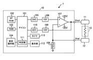
図1は、本発明の一実施形態による携帯型のGVS装置1の回路ブロック図である。GVS装置1は、左右一対の電極パッドにそれぞれアウト側の電極11及びリターン側の電極12を埋め込んだ耳掛け式の電極装着具と、ケーブルを介して電極11、12にノイズ刺激電流を出力するコントローラ10とを備え構成される。 FIG. 1 is a circuit block diagram of a
なお、図示はしないが、電極装着具は、略半円弧索状の弾性フレームと、その両先端部分に各電極11、12をそれぞれ埋め込んだ電極パッド及び耳掛け部を有している。弾性フレームを患者の首の後ろ側に掛け回して、各先端部の耳掛け部を左右の外耳に引っ掛けて装着することにより、各電極11、12を左右の耳たぶの後部に密着させることができる。電極11、12を介して耳たぶの後部から微弱なホワイトノイズ電流を体内に流すことで、内耳奥にある末梢前庭を刺激し、神経系に適度な反応を生じさせることができる。 Although not shown, the electrode mounting tool has a substantially semicircular arc-shaped elastic frame, an electrode pad in which
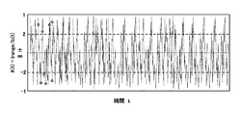
コントローラ10のEPROM102には、例えば図2に示すようなホワイトノイズ波形のノイズ電気刺激ソースデータが複数種類記憶されている。ホワイトノイズとは、あらゆる周波数成分を同等に含むノイズである。時間経過とともに振幅及び周期がランダムに変化するホワイトノイズで刺激することで、複数の患者において有意な歩行速度の増加が認められている。EPROM102には、例えば200秒間のホワイトノイズを模したソース波形データが記憶されており、マイコン101がこの200秒を1周期とするホワイトノイズを繰り返し再現することにより、長時間連続したノイズ波形の電気刺激を形成することができる。 The EPROM 102 of the
RAM103には、設定されたホワイトノイズの波形識別情報、電流レンジ設定値、連続動作時間(設定時間ともいう。)等の設定情報が一時的に記憶されている。これらノイズ波形、電流レンジ、設定時間等といったGVS装置1の動作条件は、設定操作部104から入力及び変更することができる。 The
ここで、電流レンジとは、ノイズ電気刺激として電極11、12から出力する電流範囲をいい、電流レンジ設定値(Irange)とは、設定された電流レンジにおける最大電流の絶対値を意味する。この電流レンジは、患者の年齢、性別、体機能障害の程度等に応じ、予め患者の最適刺激レベルを試験することで決められる。なお、その日の患者の体調等に応じて適宜設定してもよい。 Here, the current range means the current range output from the
マイコン101は、ホワイトノイズを模した波形データをEPROM102から読み取り、設定された電流レンジに合わせて、読み取った波形データに従う電流指令値Ic(t)をDA変換部105に出力する。ここで、電流指令値Ic(t)は、設定された電流レンジにおけるノイズ電気刺激の波形を形成する、時間tに依存するデジタルの指令値であり、DA変換部105によりロジックレベル(0〜5V)の電圧値に変換される。そして更に電流指令値は、レベルシフト回路部106により、ロジックレベルから±20Vの駆動レベルに変換される。 The
電圧−電流変換部107は、電流指令値Ic(t)に従ったノイズ刺激電流が、一対の電極11、12を介して患者の体内(体内抵抗13)を流れるようフィードバック制御されるオペアンプ回路により構成される。電圧−電流変換部107のアウト側電極11から患者の体内に流れる電流は、体内抵抗13を経てリターン側抵抗12により回収され、その値が電流検出抵抗108により検出される。電流検出抵抗108により検出された電圧値は、電圧−電流変換部107(オペアンプの負入力)にフィードバックされ、レベルシフト回路部106の出力である±20Vの電流指令値と比較されることにより、電圧−電流変換が行われる。 The voltage-
マイコン101は、タイマ113が設定時間のカウントを終了するまで、上記シーケンスを繰り返すことにより、ホワイトノイズを模した電気刺激が電極11、12を介して設定時間連続して患者に与えられる。GVS装置1が正常に動作する間、表示部112には、例えば図5に示すように、設定時間及び経過時間とともに、ホワイトノイズの波形(例えば「B」)、電流レンジ(例えば「±150μA」)、後述する出力レベル(例えば「3」)等の動作情報が表示される。このような数値や文字情報を表示する表示部112として、例えばLEDドットマトリクス表示器を用いることができる。 By repeating the above sequence until the timer 113 finishes counting the set time, the
本実施形態によるGVS装置1は、電極11、12が外れた場合やケーブルの断線を判定する断線検出部を備えている。断線検出部は、図1に示されるレベルシフト回路部109、AD変換部110及び判定部111を備えて構成される。電圧−電流変換部107により電極11から出力される±20Vレンジの出力電圧は、レベルシフト回路部109により5Vレンジのロジックレベルの電圧値に降圧される。そしてロジックレベルの出力電圧がAD変換部110によりデジタル値に変換されマイコン101に入力される。判定部111は、電圧−電流変換部107の出力電圧(又は電極11、12間の電圧)が±20Vに振り切れた場合に断線(又は電極11、12が皮膚から剥がれている)と判定する。マイコン101は、断線を検出すると、動作停止及びエラー報知等のエラー処理を実行する。 The
電極11、12が皮膚から剥がれかけていたり、汗で電極11、12が浮きかけたり、又は皮膚が乾燥していて皮膚抵抗が高いままGVS装置1の使用を継続すると、電極11、12間の抵抗が増加して断線と誤判定され、刺激が度々中断する場合がある。本実施形態によるGVS装置1は、そのような電極11、12と皮膚との密着不良等による望ましくない中断を回避するために、出力レベル表示機能を有している。出力レベル表示機能は、上述の断線検出部を利用して、マイコン101の判定部111がノイズ電気刺激の出力レベルを随時判定し、例えば5段階(数字又はバー表示等でもよい)で表示部に112に出力レベルを表示する。
電極11、12の出力電圧は、電極11、12と皮膚との電気抵抗(インピーダンス)に影響されるので、電気刺激の出力レベルを段階的に表示することで、電極11、12が皮膚にしっかりと貼り付いているか又は剥がれかけた状態か、又は皮膚抵抗が高い状態かを利用者に知らせることができる。このように電気刺激の出力レベルを表示することにより、断線エラーと判定される前に、電極を抑えて密着させるとか、ケーブルが引っ張られないよう気を付けるとか、ケーブルの配置を変更するとか、又は利用者に電極11、12の貼り直しを促すことができ、電極11、12の密着不良による電気刺激の中断を事前に回避することができる。If the
Since the output voltage of the
以下、本発明において特徴的な出力レベル表示機能の具体的な実施例をフローチャートに基づいて説明する。出力レベル表示機能は、マイコン101のCPU(判定部111)が演算処理を実行することにより実現される機能である。 Hereinafter, specific examples of the characteristic output level display function in the present invention will be described with reference to the flowchart. The output level display function is a function realized by the CPU (determination unit 111) of the
(実施例1)
図3を参照し、実施例1による出力レベル表示処理を具体的に説明する。処理が起動されると、マイコン101は、タイマ113の時間カウンタを初期化し、時間の計測を開始する(ステップS11)。また、電極11から出力するノイズ電気刺激の最大出力電圧VoutMaxを0に初期化する(ステップS12)。ここで、VoutMaxは、ノイズ電気刺激の最大出力電圧の値を格納する変数である。(Example 1)
The output level display process according to the first embodiment will be specifically described with reference to FIG. When the process is started, the
判定部111は、電極11又は出力段オペアンプ107の出力電圧Voutの絶対値|Vout|が19V以上かを判断する(ステップS13)。出力電圧Voutが±19V以上に振り切れていれば(ステップS13:Yes)、マイコン101は、動作停止及びエラー報知等の断線エラー処理を行う(ステップS14)。
なお、判定部111(断線検出部)は、一対の電極11、12間の電圧Vout_dを監視し、Vout_dが±19V以上に振り切れたときに断線エラーと判定してもよい。The
The determination unit 111 (disconnection detection unit) may monitor the voltage Vout_d between the pair of
出力電圧の絶対値|Vout|が19Vよりも小さければ(ステップS13:No)、正常動作中と判断され、判定部111は、次に出力電圧の絶対値|Vout|と、上述の最大出力電圧VoutMaxとを比較する(ステップS15)。|Vout|>VoutMaxであれば(ステップS15:Yes)、最大出力電圧VoutMaxが、出力電圧の絶対値|Vout|に更新される(ステップS16)。 If the absolute value | Vout | of the output voltage is smaller than 19V (step S13: No), it is determined that normal operation is in progress, and the
なお、断線検出と同様に、電極11、12間の電圧Vout_dを監視し、その最大値により上記の最大出力電圧VoutMaxを更新してもよい。 As in the case of disconnection detection, the voltage Vout_d between the
判定部111は、上述の断線判定処理(ステップS13)及び最大出力電圧の検出処理(ステップS15、S16)を、タイマ113が所定時間である例えば1分を計測するまで繰り返す(ステップS17)。そして、起動から1分を経過したタイミングで(ステップS17:Yes)、判定部111は、その1分間に出力されたノイズ電気刺激の最大出力電圧VoutMaxのレベルを判定する(ステップS18)。 The
例えば図4に示すように、最大出力電圧VoutMaxの値に応じて5段階のレベルが判断される。電極11、12と皮膚との密着状態が悪い(つまり電極が剥がれかけている)程、接点のインピーダンスが高くなる。電極11、12と皮膚とのインピーダンスが高まれば、最大出力電圧VoutMaxも大きくなることから、出力レベルによって電極11、12と皮膚との密着状態を示すことができる。 For example, as shown in FIG. 4, five levels are determined according to the value of the maximum output voltage VoutMax. The poorer the contact state between the
マイコン101は、判定部111が判定した出力レベルを、例えば図5に示すように数字で表示部112に表示する(ステップS19)。また、出力レベルに応じて、メッセージを表示してもよい。例えば、レベル「5」であれば、「電極が剥がれかけています。もう一度貼り直してください。」、また、レベル「4」であれば、「電極が剥がれかけています。確認してください。」のような警告又は注意文を出力レベルの数字の脇に併記することができる。 The
本実施形態のGVS装置1によれば、電極11、12から出力されるノイズ電気刺激の出力レベルを常時監視するとともに、表示部112に出力レベルを段階的に表示する。これにより、断線エラーと判定される前に、利用者に電極11、12の貼り直しを促すことができ、電極11、12と皮膚との密着不良による電気刺激の中断を事前に回避することができる。 According to the
(実施例2)
他の実施形態として、判定部111は、上述の電流指令値Ic(t)から推定されるノイズ電気刺激の最大出力電圧VoutMaxを演算し、出力レベルを判定してもよい。(Example 2)
As another embodiment, the
ここで、最大出力電圧VoutMaxを演算するための変換係数K(t)を、下記の式(1)で定義する。
変換係数K(t)=電流レンジ設定値Irange/電流指令値Ic(t) ・・・式(1)
最大出力電圧VoutMax(t)は、下記の式(2)を用いて、すなわち出力電圧Voutに変換係数K(t)を乗算することにより推定することができる。
最大出力電圧VoutMax(t)=変換係数K(t)×出力電圧Vout ・・・式(2)
Here, the conversion coefficient K (t) for calculating the maximum output voltage VoutMax is defined by the following equation (1).
Conversion coefficient K (t) = Current range set value Irange / Current command value Ic (t) ・ ・ ・ Equation (1)
The maximum output voltage VoutMax (t) can be estimated using the following equation (2), that is, by multiplying the output voltage Vout by the conversion coefficient K (t).
Maximum output voltage VoutMax (t) = conversion coefficient K (t) x output voltage Vout ・ ・ ・ Equation (2)
しかし、電流指令値Ic(t)から最大出力電圧VoutMaxを推定する数式(1)、(2)の方法においては、指令値Ic(t)の電流が小さくなるほど精度が悪くなり、また皮膚の静電容量によっては実際に出力されるノイズ波形がなまり、そのため、最大出力電圧VoutMaxに誤差が生ることがある。そこで、より精度を高めるため、図6のフローチャートに示すように、ノイズ刺激の電流値が一定以上大きい範囲で平均化した最大出力電圧平均VoutMaxMeanに基づいて、出力レベルを判定することが好ましい。そこで、図6を参照し、実施例2による出力レベル表示処理を具体的に説明する。 However, in the methods (1) and (2) for estimating the maximum output voltage VoutMax from the current command value Ic (t), the accuracy becomes worse as the current of the command value Ic (t) becomes smaller, and the skin is still. Depending on the capacitance, the noise waveform that is actually output is blunted, which may cause an error in the maximum output voltage VoutMax. Therefore, in order to further improve the accuracy, it is preferable to determine the output level based on the maximum output voltage average VoutMaxMean averaged in a range in which the current value of the noise stimulus is larger than a certain level, as shown in the flowchart of FIG. Therefore, the output level display process according to the second embodiment will be specifically described with reference to FIG.
マイコン101は、先ず出力電圧Voutの平均を演算するため、出力電圧Voutを計測する回数であるカウント変数Countを初期化する(ステップS21)。ここでは、カウント変数Countの初期値として、例えば8が入力される。
また、マイコン101は、最大出力電圧の積算値を格納する変数Sumを0に初期化する(ステップS22)。First, the
Further, the
判定部111は、電極11(又は出力段オペアンプ107)の出力電圧Voutの絶対値|Vout|が19V以上かを判断する(ステップS23)。出力電圧Voutが±19V以上に振り切れていれば(ステップS23:Yes)、マイコン101は、動作停止及びエラー報知等の断線エラー処理を行う(ステップS24)。 The
出力電圧の絶対値|Vout|が19Vよりも小さければ(ステップS23:No)、正常動作中と判断される。判定部111は、上述の式(1)を用い、電流レンジ設定値Irange及び現時点の電流指令値Ic(t)から変換係数K(t)を演算する(ステップS25)。 If the absolute value | Vout | of the output voltage is smaller than 19V (step S23: No), it is determined that normal operation is in progress. The
判定部111は、変換係数K(t)の絶対値|K(t)|が1以上かつ2以下か判断する(ステップS26)。 The
ここで、電流指令値Ic(t)は、マイコン101により下記式(3)の範囲で指令される。
−Irange≦Ic(t)≦+Irange ・・・式(3)
上記式(1)、(3)によれば、変換係数K(t)は、−∞から−1及び+1から+∞の値となる。ここで、図7に、ホワイトノイズ電気刺激の波形と変換係数K(t)との関係を例示する。同図から容易に理解できるように、ステップS26で判断される、変換係数の絶対値|K(t)|が1以上かつ2以下とは、電流指令値Ic(t)、すなわちノイズ刺激の電流値が電流レンジの1/2よりも大きい範囲であることを意味する。Here, the current command value Ic (t) is commanded by the
−Irange ≤ Ic (t) ≤ + Irange ・ ・ ・ Equation (3)
According to the above equations (1) and (3), the conversion coefficient K (t) is a value from −∞ to -1 and from +1 to +∞. Here, FIG. 7 illustrates the relationship between the waveform of the white noise electrical stimulation and the conversion coefficient K (t). As can be easily understood from the figure, the absolute value | K (t) | of the conversion coefficient determined in step S26 is 1 or more and 2 or less, that is, the current command value Ic (t), that is, the noise stimulation current. It means that the value is in the range larger than 1/2 of the current range.
判定部111は、ノイズ電気刺激の電流指令値が電流レンジの1/2よりも大きい場合に限り(ステップS26:Yes)、上記の式(2)を使って、最大出力電圧VoutMax(t)を演算し、その演算した値を変数Sumに積算する(ステップS27)。そして、カウント変数Countの値を1だけデクリメントする(ステップS28)。 The
判定部111は、上述の断線判定処理(ステップS23)及び最大出力電圧の積算処理(ステップS27、S28)を、所定回数(例えば8回)繰り返す(ステップS29)。判定部111は、カウント変数Countの値が0になったと判断すると(ステップS29:Yes)、変数Sumをカウント変数Countの初期値8で除算して(ステップS30)、最大出力電圧平均VoutMaxMeanを求める(ステップS30)。 The
なお、判定部111は、電極11、12間の電圧Vout_dに変換係数K(t)を乗算して最大出力電圧の平均を求めてもよい。 The
そして、判定部111は、求めた最大出力電圧平均VoutMaxMeanのレベルを、例えば5段階で判定する(ステップS31)。 Then, the
そして、マイコン101は、判定部111が判定した出力レベルを表示部112に表示する(ステップS32)。 Then, the
このような処理の出力レベル表示機能により、GVS装置1が断線エラーと判定する前に、利用者に電極11、12の密着不良による貼り直しを促すことができ、電気刺激の中断を事前に回避することができる。 The output level display function of such processing can prompt the user to reattach the
1 GVS装置
10 コントローラ
11 電極(アウト側)
12 電極(リターン側)
13 体内抵抗
101 マイコン
102 EPROM
103 RAM
104 設定操作部
105 DA変換部
106 レベルシフト回路部
107 電圧−電流変換部
108 電流検出抵抗
109 レベルシフト回路部
110 AD変換部
111 判定部
112 表示部
113 タイマ1
12 Electrodes (return side)
13
103 RAM
104
Claims (1)
Translated fromJapanese前記電極から出力される前記ノイズ電気刺激の出力レベルを判定する判定部と、判定された前記出力レベルを段階的に表示する表示部と、
患者ごとに設定される電流レンジ設定値を記憶する電流レンジ記憶部と、
前記ノイズ電気刺激の波形を形成する電流指令値に従った電流を前記電極から出力する電流変換部とを備え、
ここで、変換係数Kが、
変換係数K=電流レンジ設定値/電流指令値
で定義されるものとし、
前記判定部は、前記ノイズ電気刺激の出力電圧に前記変換係数Kを乗算することにより、推定される前記ノイズ電気刺激の最大出力電圧を演算し、前記変換係数Kが1以上かつ所定値以下であるときの前記最大出力電圧の平均に基づいて前記出力レベルを判定する、前庭電気刺激装置。A vestibular electrical stimulator that applies noise electrical stimulation to the patient's peripheral vestibular system via a pair of electrodes in close contact with the patient's skin.
A determination unit that determines the output level of the noise electrical stimulation output from the electrode, a display unit that displays the determined output level stepwise, and a display unit.
A current range storage unit that stores the current range setting value set for each patient,
It is provided with a current conversion unit that outputs a current according to a current command value forming a waveform of the noise electrical stimulation from the electrode.
Here, the conversion coefficient K is
Conversion coefficient K = current range set value / current command value shall be defined.
The determination unit calculates the estimated maximum output voltage of the noise electrical stimulation by multiplying the output voltage of the noise electrical stimulation by the conversion coefficient K, and the conversion coefficient K is 1 or more and a predetermined value or less. A vestibular electrical stimulator that determines the output level based on the average of the maximum output voltages at a given time.
Priority Applications (1)
| Application Number | Priority Date | Filing Date | Title |
|---|---|---|---|
| JP2019180880AJP6903109B2 (en) | 2019-09-30 | 2019-09-30 | Vestibular electrical stimulator |
Applications Claiming Priority (1)
| Application Number | Priority Date | Filing Date | Title |
|---|---|---|---|
| JP2019180880AJP6903109B2 (en) | 2019-09-30 | 2019-09-30 | Vestibular electrical stimulator |
Publications (2)
| Publication Number | Publication Date |
|---|---|
| JP2021053247A JP2021053247A (en) | 2021-04-08 |
| JP6903109B2true JP6903109B2 (en) | 2021-07-14 |
Family
ID=75271770
Family Applications (1)
| Application Number | Title | Priority Date | Filing Date |
|---|---|---|---|
| JP2019180880AExpired - Fee RelatedJP6903109B2 (en) | 2019-09-30 | 2019-09-30 | Vestibular electrical stimulator |
Country Status (1)
| Country | Link |
|---|---|
| JP (1) | JP6903109B2 (en) |
Family Cites Families (3)
| Publication number | Priority date | Publication date | Assignee | Title |
|---|---|---|---|---|
| JPS61171943U (en)* | 1985-04-15 | 1986-10-25 | ||
| WO2017150795A1 (en)* | 2016-02-29 | 2017-09-08 | Samsung Electronics Co., Ltd. | Video display apparatus and method for reducing vr sickness |
| US10207101B2 (en)* | 2016-03-24 | 2019-02-19 | Vivonics, Inc. | System and method for suppressing vestibular activity of a human subject |
- 2019
- 2019-09-30JPJP2019180880Apatent/JP6903109B2/ennot_activeExpired - Fee Related
Also Published As
| Publication number | Publication date |
|---|---|
| JP2021053247A (en) | 2021-04-08 |
Similar Documents
| Publication | Publication Date | Title |
|---|---|---|
| US12226645B2 (en) | Medical device operational modes | |
| US11247040B2 (en) | Dynamic control of transcutaneous electrical nerve stimulation therapy using continuous sleep detection | |
| US10335595B2 (en) | Dynamic control of transcutaneous electrical nerve stimulation therapy using continuous sleep detection | |
| JP6322194B2 (en) | Neurofeedback system | |
| CN106488740B (en) | System and method for adjusting intensity of sensory stimulation during sleep based on sleep spindle waves | |
| RU2740675C2 (en) | System for increasing a user's sleep efficiency | |
| CN110799092A (en) | Method and system for modulating stimulation of the brain with a biosensor | |
| JP2019508083A (en) | Neurovascular stimulation device | |
| US11284842B2 (en) | Method of assessing the reliability of a blood pressure measurement and an apparatus for implementing the same | |
| JP2019518566A (en) | System and method for adjusting the volume of auditory stimuli during sleep based on sleep depth latency | |
| JP6684798B2 (en) | Method and apparatus for adjusting a surveillance system | |
| JP3231512U (en) | Vestibular electrical stimulator | |
| JP6903109B2 (en) | Vestibular electrical stimulator | |
| US20220210586A1 (en) | Automatic tinnitus masker for an ear-wearable electronic device | |
| CN104665800A (en) | Blood pressure management device and method | |
| JP7145484B2 (en) | Masticatory motion measuring device, masticatory motion measuring method, and method for acquiring data related to masticatory motion | |
| JPWO2020026880A1 (en) | Active electrodes, electroencephalographs, control devices, and control methods | |
| JP2022131920A (en) | Vestibular electrical stimulator | |
| JPH11253560A (en) | Low frequency medical treatment apparatus | |
| CN114786574A (en) | Wearable sensor apparatus and sensing method | |
| CN114867413A (en) | Methods and systems for the enhancement of slow wave activity and their personalized measurement | |
| US20250017503A1 (en) | Determination method for a psychiatric disorder, program, determination device for a psychiatric disorder, and determination system for a psychiatric disorder | |
| JP2025063472A (en) | Teeth grinding prevention device | |
| JP2025063470A (en) | Detector | |
| JP2024144973A (en) | Management system, management method and program |
Legal Events
| Date | Code | Title | Description |
|---|---|---|---|
| A621 | Written request for application examination | Free format text:JAPANESE INTERMEDIATE CODE: A621 Effective date:20200218 | |
| A521 | Request for written amendment filed | Free format text:JAPANESE INTERMEDIATE CODE: A523 Effective date:20200623 | |
| A131 | Notification of reasons for refusal | Free format text:JAPANESE INTERMEDIATE CODE: A131 Effective date:20201215 | |
| A521 | Request for written amendment filed | Free format text:JAPANESE INTERMEDIATE CODE: A523 Effective date:20210121 | |
| A131 | Notification of reasons for refusal | Free format text:JAPANESE INTERMEDIATE CODE: A131 Effective date:20210511 | |
| A521 | Request for written amendment filed | Free format text:JAPANESE INTERMEDIATE CODE: A523 Effective date:20210520 | |
| TRDD | Decision of grant or rejection written | ||
| A01 | Written decision to grant a patent or to grant a registration (utility model) | Free format text:JAPANESE INTERMEDIATE CODE: A01 Effective date:20210616 | |
| A61 | First payment of annual fees (during grant procedure) | Free format text:JAPANESE INTERMEDIATE CODE: A61 Effective date:20210622 | |
| R150 | Certificate of patent or registration of utility model | Ref document number:6903109 Country of ref document:JP Free format text:JAPANESE INTERMEDIATE CODE: R150 | |
| LAPS | Cancellation because of no payment of annual fees |