JP6902533B2 - Hub for device placement with shape detection system - Google Patents
Hub for device placement with shape detection systemDownload PDFInfo
- Publication number
- JP6902533B2 JP6902533B2JP2018516149AJP2018516149AJP6902533B2JP 6902533 B2JP6902533 B2JP 6902533B2JP 2018516149 AJP2018516149 AJP 2018516149AJP 2018516149 AJP2018516149 AJP 2018516149AJP 6902533 B2JP6902533 B2JP 6902533B2
- Authority
- JP
- Japan
- Prior art keywords
- hub
- shape
- shape detection
- rotation
- wire
- Prior art date
- Legal status (The legal status is an assumption and is not a legal conclusion. Google has not performed a legal analysis and makes no representation as to the accuracy of the status listed.)
- Active
Links
Images


Classifications
- A—HUMAN NECESSITIES
- A61—MEDICAL OR VETERINARY SCIENCE; HYGIENE
- A61M—DEVICES FOR INTRODUCING MEDIA INTO, OR ONTO, THE BODY; DEVICES FOR TRANSDUCING BODY MEDIA OR FOR TAKING MEDIA FROM THE BODY; DEVICES FOR PRODUCING OR ENDING SLEEP OR STUPOR
- A61M25/00—Catheters; Hollow probes
- A61M25/0097—Catheters; Hollow probes characterised by the hub
- A—HUMAN NECESSITIES
- A61—MEDICAL OR VETERINARY SCIENCE; HYGIENE
- A61B—DIAGNOSIS; SURGERY; IDENTIFICATION
- A61B5/00—Measuring for diagnostic purposes; Identification of persons
- A61B5/06—Devices, other than using radiation, for detecting or locating foreign bodies ; Determining position of diagnostic devices within or on the body of the patient
- A61B5/065—Determining position of the probe employing exclusively positioning means located on or in the probe, e.g. using position sensors arranged on the probe
- A—HUMAN NECESSITIES
- A61—MEDICAL OR VETERINARY SCIENCE; HYGIENE
- A61B—DIAGNOSIS; SURGERY; IDENTIFICATION
- A61B34/00—Computer-aided surgery; Manipulators or robots specially adapted for use in surgery
- A61B34/20—Surgical navigation systems; Devices for tracking or guiding surgical instruments, e.g. for frameless stereotaxis
- A—HUMAN NECESSITIES
- A61—MEDICAL OR VETERINARY SCIENCE; HYGIENE
- A61F—FILTERS IMPLANTABLE INTO BLOOD VESSELS; PROSTHESES; DEVICES PROVIDING PATENCY TO, OR PREVENTING COLLAPSING OF, TUBULAR STRUCTURES OF THE BODY, e.g. STENTS; ORTHOPAEDIC, NURSING OR CONTRACEPTIVE DEVICES; FOMENTATION; TREATMENT OR PROTECTION OF EYES OR EARS; BANDAGES, DRESSINGS OR ABSORBENT PADS; FIRST-AID KITS
- A61F2/00—Filters implantable into blood vessels; Prostheses, i.e. artificial substitutes or replacements for parts of the body; Appliances for connecting them with the body; Devices providing patency to, or preventing collapsing of, tubular structures of the body, e.g. stents
- A61F2/02—Prostheses implantable into the body
- A61F2/04—Hollow or tubular parts of organs, e.g. bladders, tracheae, bronchi or bile ducts
- A61F2/06—Blood vessels
- A61F2/07—Stent-grafts
- A—HUMAN NECESSITIES
- A61—MEDICAL OR VETERINARY SCIENCE; HYGIENE
- A61F—FILTERS IMPLANTABLE INTO BLOOD VESSELS; PROSTHESES; DEVICES PROVIDING PATENCY TO, OR PREVENTING COLLAPSING OF, TUBULAR STRUCTURES OF THE BODY, e.g. STENTS; ORTHOPAEDIC, NURSING OR CONTRACEPTIVE DEVICES; FOMENTATION; TREATMENT OR PROTECTION OF EYES OR EARS; BANDAGES, DRESSINGS OR ABSORBENT PADS; FIRST-AID KITS
- A61F2/00—Filters implantable into blood vessels; Prostheses, i.e. artificial substitutes or replacements for parts of the body; Appliances for connecting them with the body; Devices providing patency to, or preventing collapsing of, tubular structures of the body, e.g. stents
- A61F2/95—Instruments specially adapted for placement or removal of stents or stent-grafts
- A—HUMAN NECESSITIES
- A61—MEDICAL OR VETERINARY SCIENCE; HYGIENE
- A61M—DEVICES FOR INTRODUCING MEDIA INTO, OR ONTO, THE BODY; DEVICES FOR TRANSDUCING BODY MEDIA OR FOR TAKING MEDIA FROM THE BODY; DEVICES FOR PRODUCING OR ENDING SLEEP OR STUPOR
- A61M25/00—Catheters; Hollow probes
- A61M25/01—Introducing, guiding, advancing, emplacing or holding catheters
- A61M25/09—Guide wires
- A61M25/09041—Mechanisms for insertion of guide wires
- A—HUMAN NECESSITIES
- A61—MEDICAL OR VETERINARY SCIENCE; HYGIENE
- A61M—DEVICES FOR INTRODUCING MEDIA INTO, OR ONTO, THE BODY; DEVICES FOR TRANSDUCING BODY MEDIA OR FOR TAKING MEDIA FROM THE BODY; DEVICES FOR PRODUCING OR ENDING SLEEP OR STUPOR
- A61M25/00—Catheters; Hollow probes
- A61M25/10—Balloon catheters
- A—HUMAN NECESSITIES
- A61—MEDICAL OR VETERINARY SCIENCE; HYGIENE
- A61B—DIAGNOSIS; SURGERY; IDENTIFICATION
- A61B34/00—Computer-aided surgery; Manipulators or robots specially adapted for use in surgery
- A61B34/20—Surgical navigation systems; Devices for tracking or guiding surgical instruments, e.g. for frameless stereotaxis
- A61B2034/2046—Tracking techniques
- A61B2034/2051—Electromagnetic tracking systems
- A—HUMAN NECESSITIES
- A61—MEDICAL OR VETERINARY SCIENCE; HYGIENE
- A61B—DIAGNOSIS; SURGERY; IDENTIFICATION
- A61B34/00—Computer-aided surgery; Manipulators or robots specially adapted for use in surgery
- A61B34/20—Surgical navigation systems; Devices for tracking or guiding surgical instruments, e.g. for frameless stereotaxis
- A61B2034/2046—Tracking techniques
- A61B2034/2061—Tracking techniques using shape-sensors, e.g. fiber shape sensors with Bragg gratings
- A—HUMAN NECESSITIES
- A61—MEDICAL OR VETERINARY SCIENCE; HYGIENE
- A61B—DIAGNOSIS; SURGERY; IDENTIFICATION
- A61B5/00—Measuring for diagnostic purposes; Identification of persons
- A61B5/06—Devices, other than using radiation, for detecting or locating foreign bodies ; Determining position of diagnostic devices within or on the body of the patient
- A61B5/065—Determining position of the probe employing exclusively positioning means located on or in the probe, e.g. using position sensors arranged on the probe
- A61B5/066—Superposing sensor position on an image of the patient, e.g. obtained by ultrasound or x-ray imaging
- A—HUMAN NECESSITIES
- A61—MEDICAL OR VETERINARY SCIENCE; HYGIENE
- A61B—DIAGNOSIS; SURGERY; IDENTIFICATION
- A61B90/00—Instruments, implements or accessories specially adapted for surgery or diagnosis and not covered by any of the groups A61B1/00 - A61B50/00, e.g. for luxation treatment or for protecting wound edges
- A61B90/90—Identification means for patients or instruments, e.g. tags
- A—HUMAN NECESSITIES
- A61—MEDICAL OR VETERINARY SCIENCE; HYGIENE
- A61M—DEVICES FOR INTRODUCING MEDIA INTO, OR ONTO, THE BODY; DEVICES FOR TRANSDUCING BODY MEDIA OR FOR TAKING MEDIA FROM THE BODY; DEVICES FOR PRODUCING OR ENDING SLEEP OR STUPOR
- A61M25/00—Catheters; Hollow probes
- A61M25/01—Introducing, guiding, advancing, emplacing or holding catheters
- A61M25/0105—Steering means as part of the catheter or advancing means; Markers for positioning
- A61M2025/0166—Sensors, electrodes or the like for guiding the catheter to a target zone, e.g. image guided or magnetically guided
- A—HUMAN NECESSITIES
- A61—MEDICAL OR VETERINARY SCIENCE; HYGIENE
- A61M—DEVICES FOR INTRODUCING MEDIA INTO, OR ONTO, THE BODY; DEVICES FOR TRANSDUCING BODY MEDIA OR FOR TAKING MEDIA FROM THE BODY; DEVICES FOR PRODUCING OR ENDING SLEEP OR STUPOR
- A61M2205/00—General characteristics of the apparatus
- A61M2205/33—Controlling, regulating or measuring
- A61M2205/3306—Optical measuring means
- A—HUMAN NECESSITIES
- A61—MEDICAL OR VETERINARY SCIENCE; HYGIENE
- A61M—DEVICES FOR INTRODUCING MEDIA INTO, OR ONTO, THE BODY; DEVICES FOR TRANSDUCING BODY MEDIA OR FOR TAKING MEDIA FROM THE BODY; DEVICES FOR PRODUCING OR ENDING SLEEP OR STUPOR
- A61M2205/00—General characteristics of the apparatus
- A61M2205/50—General characteristics of the apparatus with microprocessors or computers
- A61M2205/502—User interfaces, e.g. screens or keyboards
- A—HUMAN NECESSITIES
- A61—MEDICAL OR VETERINARY SCIENCE; HYGIENE
- A61M—DEVICES FOR INTRODUCING MEDIA INTO, OR ONTO, THE BODY; DEVICES FOR TRANSDUCING BODY MEDIA OR FOR TAKING MEDIA FROM THE BODY; DEVICES FOR PRODUCING OR ENDING SLEEP OR STUPOR
- A61M25/00—Catheters; Hollow probes
- A61M25/01—Introducing, guiding, advancing, emplacing or holding catheters
- A61M25/0105—Steering means as part of the catheter or advancing means; Markers for positioning
- A61M25/0108—Steering means as part of the catheter or advancing means; Markers for positioning using radio-opaque or ultrasound markers
Landscapes
- Health & Medical Sciences (AREA)
- Life Sciences & Earth Sciences (AREA)
- Engineering & Computer Science (AREA)
- Biomedical Technology (AREA)
- Heart & Thoracic Surgery (AREA)
- Public Health (AREA)
- Animal Behavior & Ethology (AREA)
- General Health & Medical Sciences (AREA)
- Veterinary Medicine (AREA)
- Biophysics (AREA)
- Pulmonology (AREA)
- Surgery (AREA)
- Hematology (AREA)
- Anesthesiology (AREA)
- Medical Informatics (AREA)
- Molecular Biology (AREA)
- Vascular Medicine (AREA)
- Cardiology (AREA)
- Oral & Maxillofacial Surgery (AREA)
- Transplantation (AREA)
- Pathology (AREA)
- Human Computer Interaction (AREA)
- Physics & Mathematics (AREA)
- Gastroenterology & Hepatology (AREA)
- Nuclear Medicine, Radiotherapy & Molecular Imaging (AREA)
- Robotics (AREA)
- Child & Adolescent Psychology (AREA)
- Endoscopes (AREA)
- Prostheses (AREA)
Description
Translated fromJapanese本開示は、医用器具に関し、より具体的には、医療用途におけるオーバー・ザ・ワイヤ部品を検出するように構成されるガイドワイヤ内の形状検出光ファイバに関する。 The present disclosure relates to medical instruments, and more specifically to shape-detecting optical fibers in guidewires configured to detect over-the-wire components in medical applications.
カテーテル、展開システム、又はシースなどの医療装置は、装置内に光ファイバを組み込むことによって形状検出を可能にすることができる。これは、ファイバのための更なる管腔を追加するように装置の機械的な設計をカスタマイズすることを必要とする。ファイバを追加することは、装置にコストを追加し、付加的な形状検出システムの使用を必要とする。このような装置は、一般に、装置内の管腔を通って移動するガイドワイヤと共に使用されるので、「オーバー・ザ・ワイヤ」装置として知られている。 Medical devices such as catheters, deployment systems, or sheaths can enable shape detection by incorporating optical fibers within the device. This requires customizing the mechanical design of the device to add additional lumens for the fiber. Adding fiber adds cost to the device and requires the use of additional shape detection systems. Such devices are commonly known as "over-the-wire" devices because they are commonly used with guide wires that travel through the lumen within the device.
光学形状検出(OSS)又は(光学形状検出、ファイバ形状検出、ファイバ光学3D形状検出、ファイバ光学形状センシング及びローカライゼーション等として知られる)ファイバオプティカルリアルシェイプTMは、外科的介入の間の装置の位置特定(ローカライゼーション)及びナビゲーションのためのマルチコア光ファイバに沿う光を用いる。関連する1つの原理は、特徴的なレイリー後方散乱又は制御される格子パターンを使用して光ファイバ内の分散されるひずみ測定を利用する。下部プロファイルセンサー用に螺旋状にすることもできる複数のコアを備えた単一の光ファイバ又は複数の光ファイバが一緒に使用されて3D形状を再構成することができる。光ファイバに沿った形状は、送出又はz = 0として知られる、センサに沿った特定の点で始まり、その後の形状の位置及び向きは、その点に対する相対的なものである。光学形状検出ファイバは、医療装置に組み込まれて、低侵襲プロシージャ中に装置のライブガイダンスを提供することができる。Optical Shape Detection (OSS) or Fiber Optical Real Shape TM ( known as Optical Shape Detection, Fiber Shape Detection, Fiber Optical 3D Shape Detection, Fiber Optical Shape Sensing and Localization, etc.) is a device positioning device during surgical intervention. Use light along a multi-core fiber optic for (localization) and navigation. One relevant principle utilizes distributed strain measurements in fiber optics using characteristic Rayleigh backscatter or controlled lattice patterns. A single optical fiber with multiple cores, which can also be spiral for the lower profile sensor, or multiple optical fibers can be used together to reconstruct the 3D shape. The shape along the fiber optic begins at a particular point along the sensor, known as delivery or z = 0, after which the position and orientation of the shape is relative to that point. Optical shape detection fibers can be incorporated into medical devices to provide live guidance for the device during minimally invasive procedures.
装置内の管腔を通って移動するガイドワイヤを用いて装置を位置決めし、配向させるために形状検出が使用される場合、回転情報を有することが必要である。しかしながら、ガイドワイヤ及びオーバー・ザ・ワイヤ装置は、本体内で回転可能に結合されていない。その結果、オーバー・ザ・ワイヤ装置の向きを決定する問題には対処していない。 It is necessary to have rotational information when shape detection is used to position and orient the device with guide wires that move through the lumens within the device. However, the guide wire and over-the-wire device are not rotatably coupled within the body. As a result, it does not address the issue of orienting over-the-wire devices.
本原理によれば、装置を展開するためのシステムは、細長い可撓性器具と、可撓性器具に結合される形状検出システムとを含む。ハブは、その内部に形状検出システムを備えた可撓性器具を受け入れて維持するように構成される形状プロファイルを含む。形状プロファイルは、形状検出システムを使用して基準位置に対するハブの位置又は回転をトラッキングするための形状を含む。ハブは、ハブの位置又は回転の変化が展開可能な装置における対応する変化を示すように、展開可能な装置に結合されるように構成される。 According to this principle, the system for deploying the device includes an elongated flexible device and a shape detection system coupled to the flexible device. The hub includes a shape profile configured to accept and maintain a flexible device with a shape detection system inside. The shape profile includes a shape for tracking the position or rotation of the hub with respect to a reference position using a shape detection system. The hub is configured to be coupled to the deployable device so that changes in hub position or rotation indicate the corresponding changes in the deployable device.
装置を展開するための別のシステムは、形状検出可能なガイドワイヤと、形状検出可能なガイドワイヤを受け入れて維持するように構成されるプロファイルを含むハブとを含む。プロファイルは、形状検出を使用して基準位置に対するハブの位置又は回転のうちの少なくとも1つの識別を可能にする形状を含む。オーバー・ザ・ワイヤ装置は、展開中にハブに接続可能である。レジストレーションモジュールは、解剖学的画像をハブにレジストレーションして、ハブの位置又は回転の少なくとも1つに従って装置の位置又は回転を推測する。 Another system for deploying the device includes a shape-detectable guidewire and a hub containing a profile configured to accept and maintain the shape-detectable guidewire. The profile includes a shape that allows the identification of at least one of the hub's position or rotation with respect to the reference position using shape detection. The over-the-wire device can be connected to the hub during deployment. The registration module registers the anatomical image on the hub and infers the position or rotation of the device according to at least one of the positions or rotations of the hub.
装置を展開する方法は、可撓性器具に結合される形状検出システムを有する細長い可撓性器具上にハブを取り付けるステップであって、ハブはその内部に形状検出システムと共に可撓性器具を受け入れて維持するように構成される形状プロファイルを含む、ステップと、展開される器具上のターゲット特徴を前記ハブにレジストレーションするステップと、ハブの位置又は回転の少なくとも1つの変化が、展開される器具の対応する変化を示す場合に、画像に対して形状検出システムによって提供されるハブの位置又は回転のうちの少なくとも1つを使用して、画像上の展開される器具の表現を表示するステップと、画像内の表現の位置又は回転のうちの少なくとも1つを精緻化するステップとを含む。 The method of deploying the device is to mount the hub on an elongated flexible device that has a shape detection system that is coupled to the flexible device, the hub accepting the flexible device with the shape detection system inside. A step of registering a target feature on the deployed instrument with the hub, including a shape profile configured to maintain, and an instrument in which at least one change in hub position or rotation is deployed. With the step of displaying the representation of the unfolded instrument on the image using at least one of the hub positions or rotations provided by the shape detection system for the image when showing the corresponding changes in Includes the step of refining at least one of the positions or rotations of the representation in the image.
本開示のこれら及び他の目的、特徴及び利点は、添付の図面に関連して読まれるべきその例示的な実施形態の以下の詳細な説明から明らかになるであろう。 These and other objectives, features and advantages of the present disclosure will become apparent from the following detailed description of its exemplary embodiments to be read in connection with the accompanying drawings.
本開示は、以下の図を参照して、好ましい実施形態の以下の説明を詳細に提示する。 The present disclosure presents in detail the following description of preferred embodiments with reference to the following figures.
本原理によれば、何れかの市販のオーバー・ザ・ワイヤ装置又はコンポーネントの位置も検出する、管腔での使用のための形状検出ガイドワイヤが提供される。カテーテル(又は他の展開可能な装置)が、形状検出ガイドワイヤ(又は他の可撓性の細長い装置)上に使用される場合、ガイドワイヤ形状は、カテーテルがガイドワイヤと重なる長さに対するカテーテル形状も規定する。カテーテルの位置を適切に定めるには、カテーテルとガイドワイヤとの間の関係を知る必要がある。これは、ガイドワイヤが、カテーテルに沿った特定の位置で特定の形状、湾曲、又は歪みプロファイル(形状プロファイル)を呈するようにハブ装置を使用することによってなされることができる。このような形状、曲率又はひずみプロファイルを誘起する方法は、テンプレートとして保存され得る既知のプロファイルを有する「ハブ」を使用することにある。 According to this principle, shape detection guide wires for use in the luminal are provided that also detect the position of any commercially available over-the-wire device or component. When a catheter (or other deployable device) is used on a shape-detecting guidewire (or other flexible elongated device), the guidewire shape is the catheter shape relative to the length at which the catheter overlaps the guidewire. Also stipulate. To properly position the catheter, it is necessary to know the relationship between the catheter and the guide wire. This can be done by using a hub device such that the guide wire exhibits a particular shape, curvature, or strain profile (shape profile) at a particular location along the catheter. A way to induce such a shape, curvature or strain profile is to use a "hub" with a known profile that can be stored as a template.
形状検出装置が非形状検出装置の内部にある場合、検出装置からの形状情報は非検出装置の形状及び位置に関する情報を推測するために使用され得る。必要なレジストレーションは、2つの装置間の長手方向の並進を含むことができる。このレジストレーションは、非検出装置に沿った特定の位置での検出装置の既知の形状変形を使用することによって行われることができる。形状変形は、曲率検出、(加熱又は張力による)軸方向の歪み、2D又は3D形状マッチングなどによって検出されることができる。 When the shape detector is inside the non-shape detector, the shape information from the detector can be used to infer information about the shape and position of the non-detector. The required registration can include longitudinal translation between the two devices. This registration can be done by using a known shape deformation of the detector at a particular position along the non-detector. Shape deformation can be detected by curvature detection, axial distortion (due to heating or tension), 2D or 3D shape matching, and the like.
複数の異なるバージョンのハブ設計が使用されることができる。(例えば温度による歪みの変形とは対照的に)形状の変形を用いるハブの場合、形状の変形も平面を規定する。同じハブ装置は装置の向きをトラッキングするように使用され得る(例えば、その縦軸の周りを回転する)。装置の近位部分におけるハブの方向は、遠位部分に位置するバルーン、バルブ、エンドグラフト、ステントなどのような治療器具に1対1にマッピングしてもよい。 Multiple different versions of the hub design can be used. For hubs that use shape deformation (as opposed to strain deformation due to temperature, for example), shape deformation also defines a plane. The same hub device can be used to track the orientation of the device (eg, rotate around its vertical axis). The orientation of the hub in the proximal portion of the device may be mapped one-to-one to therapeutic instruments such as balloons, valves, end grafts, stents, etc. located in the distal portion.
ハブは、ガイドワイヤのような形状検出装置において形状又は湾曲の変形を生成することができるコンポーネントとして規定されてもよい。このような構成要素は、臨床環境内の広範な市販の利用可能な医療機器で機能することができなければならない。ハブ設計は、複数の装置設計に渡って使用され得る。複数の異なるバージョンのハブ設計が、ガイドワイヤを変形させ、長手方向のエンコードを行うために使用され得る。 The hub may be defined as a component capable of producing a shape or curve deformation in a shape detector such as a guide wire. Such components must be able to function in a wide range of commercially available medical devices within the clinical environment. Hub designs can be used across multiple device designs. Multiple different versions of the hub design can be used to deform the guidewires and perform longitudinal encoding.
オーバー・ザ・ワイヤ装置の位置及び方向がわかったら、バルーン、バルブ、エンドグラフト、ステントなどの治療器具のモデルを表示するために使用され得る。血管内動脈瘤修復(EVAR)では、他のカテーテル及びエンドグラフトが元のエンドグラフトに対してナビゲートされることができるように、知られる必要がある。これは、相当量の蛍光透視とコントラストを必要とする。エンドグラフトが正しく配置されていない場合、いくつかの問題が発生する可能性がある。 Once the position and orientation of the over-the-wire device is known, it can be used to display models of therapeutic instruments such as balloons, valves, end grafts, and stents. In endovascular aneurysm repair (EVAR), other catheters and end grafts need to be known so that they can be navigated to the original end graft. This requires a significant amount of fluoroscopy and contrast. Some problems can occur if the end grafts are not placed correctly.
腹部大動脈瘤(AAA)の修復のための最も一般的な技術として、EVARが開腹手術に取って代わった。このプロシージャは、通常、X線透視ガイダンスの下で実施され、ステントグラフトを正確に配置して展開するために、かなりの量のコントラストを使用する。 EVARプロシージャ中に平均50〜100mLの造影剤が使用され、約7%の症例で急性腎不全を引き起こす可能性がある。 EVARの1つの合併症は、ステントグラフトの大動脈への不十分なシールに起因するエンドリークである。エンドリークは、ステント周囲の不正確な流れ(例えば、近位又は遠位の取り付け部位でのステント周囲の流れ、グラフト壁を通る流れ、分岐からの逆流など)を伴う。EVARに関する別の合併症は、大動脈の側枝(結腸、腎臓、及び骨盤動脈など)の虚血を伴う。これは、ステントが側枝の1つを部分的に又は完全に覆うようにステントグラフトが誤って配置されることによって生じる可能性があり、これは高品質のイメージング技術の欠如及び血管内のチームの学習曲線に関連する。 EVAR has replaced open surgery as the most common technique for repairing abdominal aortic aneurysms (AAA). This procedure is usually performed under fluoroscopic guidance and uses a significant amount of contrast to accurately position and deploy the stent graft. An average of 50-100 mL of contrast medium is used during the EVAR procedure and can cause acute renal failure in about 7% of cases. One complication of EVAR is endoleak due to inadequate sealing of the stent graft to the aorta. Endoleak involves inaccurate flow around the stent (eg, flow around the stent at the proximal or distal attachment site, flow through the graft wall, backflow from the bifurcation, etc.). Another complication of EVAR is ischemia of the lateral branches of the aorta (such as the colon, kidneys, and pelvic arteries). This can result from the mispositioning of the stent graft so that the stent partially or completely covers one of the side branches, which is a lack of high quality imaging techniques and learning of teams within the vessel. Related to curves.
EVARでは、ステントグラフトは、ステントを脈管の正しい部分にナビゲートするために使用されるステント展開システム内に含まれる。展開システムは、比較的大きくて堅い脈管内装置になる傾向がある。典型的には、ステントの展開の周りの様々なステップを制御するために、近位端にハンドル又はノブのセット及びダイヤルを含む。ステントは、装置の遠位部分内に位置し、装置が適切な位置にナビゲートされるときのみ解除される。いくつかの場合において、ステントは、一段階で完全に展開するが、他の場合には、最後のステップがステントを(典型的には保持/シールリングを介して)脈管にしっかりと取り付ける前に、ステントは部分的に展開され、正しい配置及び配向にすることができる。 In EVAR, the stent graft is contained within the stent deployment system used to navigate the stent to the correct portion of the vessel. Deployment systems tend to be relatively large and rigid intravascular devices. Typically, a set of handles or knobs and a dial at the proximal end are included to control the various steps around the deployment of the stent. The stent is located within the distal portion of the device and is only released when the device is navigated to the proper position. In some cases, the stent is fully deployed in one step, but in other cases, the last step is before the stent is firmly attached to the vessel (typically via a retention / seal ring). In addition, the stent can be partially deployed and in the correct placement and orientation.
血管内ステントグラフトは、シーリングリングを着けることができる十分な量の健全な脈管構造を必要とする。これが腎動脈下で可能でない場合、ステントはこれらの動脈を覆い、これらの血管への流れを維持するための代替手段を作り出す必要がある。これは、有窓血管内動脈瘤修復(FEVAR)として知られているプロシージャにおいて、有窓ステント(例えば、側枝用の窓を備えたステント)を用いて行われることができる。この場合、ステントは、側枝と正しく整列される開窓を有し、更なるステントは、側枝を主ステントに接続するために配置される。 Intravascular stent grafts require a sufficient amount of healthy vascular structure to allow the sealing ring to be worn. If this is not possible under the renal arteries, the stent needs to cover these arteries and create alternatives to maintain flow to these vessels. This can be done with a fenestrated stent (eg, a stent with a window for the side branch) in a procedure known as fenestrated endovascular aneurysm repair (FEVAR). In this case, the stent has an fenestration that is properly aligned with the side branch, and an additional stent is placed to connect the side branch to the main stent.
X線ガイダンスの下で、ステントは、ステント上の重要な位置に配置されるX線可視マーカーによって視覚化することができる。有窓ステントでは、マーカーは開窓の位置を識別し、開窓を側枝に適切にアラインするようにステントを配向するために使用されることができる。 Under X-ray guidance, the stent can be visualized by X-ray visibility markers placed at critical locations on the stent. In fenestrated stents, markers can be used to identify the location of the fenestration and orient the stent so that the fenestration is properly aligned with the side branch.
本原理によれば、装置及び方法は、オーバー・ザ・ワイヤ装置のターゲットノードにハブをレジストレーションするステップ、及びオーバー・ザ・ワイヤ装置内のターゲットノードでオーバー・ザ・ワイヤ装置及びモデルを視覚化するステップを含む。これにより、何れかの市販のカテーテル、展開システム、シース、又は他のそのような装置は、形状検出ガイドワイヤを用いてナビゲートされることが可能になる。有用な実施形態では、装置及び方法は、近位ハブを使用して、市販のカテーテル、展開システム、又は形状検出ガイドワイヤに適合されるシースのような装置の遠位部分の方向を決定する。ハブは、それを通るガイドワイヤを既知の形状に偏向させる形状プロファイルを含むことができる。その形状は、ファイバに沿って検出されることができ、ガイドワイヤとオーバー・ザ・ワイヤ装置との間の長手方向レジストレーションを知ることができる。ハブはオーバー・ザ・ワイヤ装置に結合されるため、ハブ形状はオーバー・ザ・ワイヤ装置の近位部に加えられる回転をトラッキングするために使用されることもできる。 According to this principle, the device and method are the steps of registering the hub at the target node of the over-the-wire device, and visualizing the over-the-wire device and model at the target node within the over-the-wire device. Including the step of becoming. This allows any commercially available catheter, deployment system, sheath, or other such device to be navigated using shape detection guide wires. In a useful embodiment, the device and method use a proximal hub to determine the orientation of the distal portion of the device, such as a sheath that is compatible with a commercially available catheter, deployment system, or shape detection guide wire. The hub can include a shape profile that deflects the guide wire through it to a known shape. Its shape can be detected along the fiber and the longitudinal registration between the guide wire and the over-the-wire device can be known. Since the hub is coupled to the over-the-wire device, the hub shape can also be used to track the rotation applied to the proximal portion of the over-the-wire device.
一実施形態では、ハブ(したがって、装置全体)の回転は、ハブ内部の既知の形状プロファイルに平面を適合させ、その平面の方向を経時的にトラッキングすることによって測定されることができる。一実施形態では、有窓エンドグラフトのモデルを回転されて、エンドグラフト上の開窓を解剖学的モデルにより良好にアラインする。ハブ形状自身の回りのハブ形状の回転は、装置の遠位部分内に収容されるエンドグラフトの回転をマッピングするために使用される。これにより、何れかの市販のカテーテル(手動又はロボット)、展開システム、シース又は他のそのような装置は、形状検出ガイドワイヤを使用してナビゲートされることが可能になる。これは、脈管(カテーテル、シース、展開システムなど)、管腔内(内視鏡)、整形外科(kワイヤ&スクリュードライバー)ならびに非医療用途などの多くの用途に適用されることができる。 In one embodiment, the rotation of the hub (and thus the entire device) can be measured by adapting a plane to a known shape profile inside the hub and tracking the direction of that plane over time. In one embodiment, the model of the fenestrated end graft is rotated to better align the fenestration on the end graft with the anatomical model. The rotation of the hub shape around the hub shape itself is used to map the rotation of the end graft contained within the distal portion of the device. This allows any commercially available catheter (manual or robotic), deployment system, sheath or other such device to be navigated using shape detection guide wires. It can be applied in many applications such as vessels (catheter, sheath, deployment system, etc.), intraluminal (endoscope), orthopedics (k-wire & screwdriver) and non-medical applications.
より効率的なレジストレーションを提供するために、(「光学形状検出」、「ファイバ形状検出」、「光ファイバ3D形状検出」、「光ファイバ形状検出及びローカリゼーション」としても知られるFORS(tm) )ファイバオプティカルリアルシェイプTM(Fiber-Optical RealShape(tm))を用いる変形可能なレジストレーションが使用されることはできる。 ファイバオプティカルリアルシェイプ(tm)システムは、コーニンクレッカ フィリップス エヌ ヴェ(Koninklijke Philips、NV)によって開発されるシステムの商用名である。ここで使用されるようにFORS(tm)及びFORS(tm)システムという用語は、コーニンクレッカ フィリップス エヌ ヴェの製品及びシステムに限定されないが、概して光ファイバ三次元形状検出システム、光ファイバ三次元形状検出システム、光ファイバ形状検出及び位置特定並びに同様の技術に関する。To provide more efficient registration (FORS (tm), also known as "optical shape detection", "fiber shape detection", "fiber optic 3D shape detection", "fiber optic shape detection and localization") may be deformable registration using fiber optical real shapeTM (fiber-optical RealShape (tm )) is used. The Fiber Optical Real Shape (tm) system is the commercial name for the system developed by Koninklijke Philips (NV). As used herein, the terms FORS (tm) and FORS (tm) systems are not limited to the products and systems of Cornincreca Phillips NV, but are generally fiber optic three-dimensional shape detection systems, fiber optic three-dimensional shape detection systems. , Optical fiber shape detection and positioning, and similar techniques.
本発明は医療器具に関して記載されることが理解される。しかしながら、本発明の教示は、はるかに広く、何れかの光ファイバ器具に適用可能である。いくつかの実施形態では、本原理は、複雑な生物学的又は機械的システムのトラッキング又は分析に用いられる。特に、本原理は、肺、胃腸管、排泄器官、血管などの身体の全ての領域における生物学的システム及びプロシージャの内部トラッキングプロシージャに適用可能である。ハードウェアとソフトウェアとの様々な組み合わせで実施することができ、単一の要素又は複数の要素に組み合わせることができる機能を提供する。 It is understood that the present invention is described with respect to medical devices. However, the teachings of the present invention are much broader and applicable to any fiber optic appliance. In some embodiments, this principle is used for tracking or analysis of complex biological or mechanical systems. In particular, this principle is applicable to internal tracking procedures of biological systems and procedures in all areas of the body such as lungs, gastrointestinal tract, excretory organs, blood vessels. It can be implemented in various combinations of hardware and software and provides functionality that can be combined into a single element or multiple elements.
図に示す様々な要素の機能は、適切なソフトウェアに関連してソフトウェアを実行することができるハードウェアだけでなく、専用のハードウェアを使用して提供することができる。プロセッサによって提供される場合、機能は、単一の専用プロセッサ、単一の共有プロセッサ、又は複数の個別プロセッサによって提供され、それらのうちのいくつかは共有されることができる。さらに、「プロセッサ」又は「コントローラ」という用語を明示的に使用することは、ソフトウェアを実行することができるハードウェアを排他的に指すものと解釈すべきではなく、暗黙的に、デジタル信号プロセッサ(DSP)ハードウェア、ソフトウェア、ランダムアクセスメモリ(「RAM」)、不揮発性記憶装置等を記憶するための「ROM」を含む。 The functionality of the various elements shown in the figure can be provided using dedicated hardware as well as hardware that can run the software in relation to the appropriate software. When provided by a processor, functionality is provided by a single dedicated processor, a single shared processor, or multiple individual processors, some of which can be shared. Moreover, the explicit use of the term "processor" or "controller" should not be construed as exclusively referring to the hardware capable of running the software, but implicitly a digital signal processor ( DSP) Includes "ROM" for storing hardware, software, random access memory ("RAM"), non-volatile storage devices, etc.
さらに、本発明の原理、態様及び実施形態、ならびにその特定の例を記載する本明細書におけるすべての記述は、その構造的及び機能的等価物の両方を包含するように意図されている。さらに、そのような等価物は、現在知られている等価物ならびに将来開発される等価物(すなわち、構造にかかわらず同じ機能を果たす何れかの開発される要素)の両方を含むことが意図される。したがって、例えば、本明細書に提示されるブロック図は、本発明の原理を具体化する例示的なシステム構成要素及び/又は回路の概念図を表すことが、当業者には理解されるであろう。同様に、何れかのフローチャート、フロー図などは、コンピュータ可読記憶媒体に実質的に表され、そのようなコンピュータ又はプロセッサが明示的に示されているか否かに関わらず、コンピュータ又はプロセッサによって実行され得る様々なプロセスを表す。 Moreover, all descriptions herein that describe the principles, embodiments and embodiments of the invention, as well as specific examples thereof, are intended to include both structural and functional equivalents thereof. Moreover, such equivalents are intended to include both currently known equivalents as well as future developed equivalents (ie, any developed element that performs the same function regardless of structure). To. Thus, for example, those skilled in the art will appreciate that the block diagrams presented herein represent conceptual diagrams of exemplary system components and / or circuits that embody the principles of the present invention. Let's do it. Similarly, any flowchart, flow diagram, etc. is substantially represented on a computer-readable storage medium and is executed by the computer or processor, whether or not such a computer or processor is explicitly indicated. Represents the various processes that get.
さらに、本発明の実施形態は、コンピュータ又は何れかの命令実行システムによって使用されるプログラムコードを提供するコンピュータ使用可能又はコンピュータ可読記憶媒体からアクセス可能なコンピュータプログラム製品の形態を取ることができる。この説明の目的のために、コンピュータ使用可能又はコンピュータ可読記憶媒体は、命令実行システム、装置、又は装置によって使用されるか、又は接続されるプログラムを含むか、記憶するか、通信するか、伝播するか、又は移送する何れかの装置になり得る。媒体は、電子、磁気、光学、電磁気、赤外線、又は半導体システム(又は装置若しくはデバイス)又は伝播媒体とすることができる。コンピュータ可読媒体の例には、半導体又は固体メモリ、磁気テープ、取り外し可能コンピュータディスケット、ランダムアクセスメモリ(RAM)、読み出し専用メモリ(ROM)、リジッド磁気ディスク及び光ディスクが含まれる。現在の光ディスクの例には、コンパクトディスク - リードオンリメモリ(CD-ROM)、コンパクトディスクリード/ライト(CD-R / W)、ブルーレイTM及びDVDが含まれる。Further, embodiments of the present invention can take the form of computer-enabled or computer-readable storage media that provide program code used by a computer or any instruction execution system. For the purposes of this description, a computer-enabled or computer-readable storage medium contains, stores, communicates, or propagates a program used or connected by an instruction execution system, device, or device. It can be either a device that does or transfers. The medium can be electronic, magnetic, optical, electromagnetic, infrared, or a semiconductor system (or device or device) or propagation medium. Examples of computer-readable media include semiconductor or solid-state memory, magnetic tape, removable computer diskettes, random access memory (RAM), read-only memory (ROM), rigid magnetic disks and optical disks. Examples of current optical discs include compact discs-read-only memory (CD-ROM), compact disc read / write (CD-R / W), Blu-rayTM and DVD.
本明細書における本発明の原理の「一実施形態」又は「実施形態」ならびにその他の変形に対する参照は、実施形態に関連して説明される特定の特徴、構造、特性などが少なくとも本原理の1つの実施形態に含まれることを意味する。したがって、明細書全体を通して様々な場所に現れる、「一実施形態では」又は「実施形態において」という語句の出現は、必ずしもすべて同じ実施形態を指しているわけではない。 References to "one embodiment" or "embodiment" as well as other variations of the principles of the invention herein have at least one particular feature, structure, property, etc. described in connection with the embodiment. Means included in one embodiment. Therefore, the appearance of the phrase "in one embodiment" or "in an embodiment" that appears in various places throughout the specification does not necessarily refer to the same embodiment.
以下の「/」、「及び/又は」、及び「少なくとも1つ」のいずれかの使用は、「A / B」、「A及び/又はB」、及び「A及びBの少なくとも一つ」の場合、1番目に列挙されるオプション(A)のみの選択、又は2番目に列挙されるオプション(B)のみの選択、又は両方のオプション(A及びB)の選択を包含することを意図している。さらなる例として、「A、B、及び/又はC」及び「A、B、及びCの少なくとも1つ」の場合、そのような表現は、1番目に列挙されるオプション(A)のみの選択、2番目に列挙(B)のみの選択、又は3番目に列挙されるオプション(C)のみの選択、又は1及び2番目に列挙されるオプション(A及びB)のみの選択、又は1及び3番目に列挙されるオプション(A及びC)のみ、又は2及び3番目に列挙されるオプション(B及びC)のみの選択、又は3つのオプション(A及びB及びC)の選択を包含することが意図される。これは、多くのアイテムが列挙されている場合、これ及び関連技術の当業者によって容易に明らかであるように、展開されてもよい。 The use of any of the following "/", "and / or", and "at least one" of "A / B", "A and / or B", and "at least one of A and B" In the case, it is intended to include the selection of only the first listed option (A), the selection of only the second listed option (B), or the selection of both options (A and B). There is. As a further example, in the case of "A, B and / or C" and "at least one of A, B, and C", such an expression is the selection of only option (A) listed first, Select only the second enumeration (B), or select only the third enumerated option (C), or select only the first and second enumerated options (A and B), or the first and third Intended to include selection of only the options listed in (A and C), or only the options listed in the second and third (B and C), or the selection of three options (A and B and C). Will be done. This may be developed if many items are listed, as will be readily apparent to those skilled in the art of this and related techniques.
また、層、領域又は材料などの要素が他の要素の「上にある」又は「上に渡って」と言及されるとき、それは他の要素の上に直接存在してもよく、又は介在要素が存在し得ることも理解される。対照的に、ある要素が他の要素の「直接上にある」又は「直接上に渡って」と言及されるとき、介在要素は存在しない。ある要素が他の要素に「接続されている」又は「結合されている」と言及されている場合、それは他の要素に直接接続又は結合されてもよく、又は介在要素が存在してもよいことも理解される。対照的に、ある要素が別の要素に「直接接続されている」又は「直接結合されている」と言及される場合、介在要素は存在しない。 Also, when an element such as a layer, region or material is referred to as "above" or "over" another element, it may be directly above the other element, or an intervening element. It is also understood that can exist. In contrast, when one element is referred to as "directly above" or "directly above" another element, there are no intervening elements. When an element is referred to as being "connected" or "connected" to another element, it may be directly connected or connected to the other element, or there may be intervening elements. It is also understood. In contrast, when one element is referred to as "directly connected" or "directly connected" to another, there are no intervening elements.
ここで同じ番号は同じ又は類似の要素を表す図面、最初に図1を参照すると、形状検出可能な装置及び他の装置を監視するためのシステム100が一実施形態に従って例示的に示されている。システム100は、プロシージャが監督及び/又は管理されるワークステーション又はコンソール112を含むことができる。ワークステーション112は、好ましくは、プログラム及びアプリケーションを記憶するための1つ又は複数のプロセッサ114及びメモリ116を含む。メモリ116は、形状検出装置又はシステム104(FORS(商標))からの光学フィードバック信号を解釈するように構成される光学検出モジュール122を記憶することができる。光検出モジュール122は、光信号フィードバック(及び他のフィードバック)を使用して、形状検出装置に関連する変形、偏向及び他の変化を再構成するように構成される。本原理によれば、医療装置又は器具102は、ガイドワイヤ又は他の細長い可撓性器具108を内部に受け入れる管腔103を含む。ガイドワイヤ108は、システム104を、それを通って受け入れるように構成される。医療装置102は、カテーテル、シース、プローブ、内視鏡、ロボット、電極、フィルタ装置、バルーン装置、移植片、ステント又は管腔を有する他の医療部品などを含むことができる。医療装置102は、オーバー・ザ・ワイヤ装置又はコンポーネントであると考えられる。医療装置102は、装置102内に構成されるか、装置102に適用(接続/結合)されるか、又は装置102内に適合するように構成されるハブ106を含む。 A drawing in which the same numbers represent the same or similar elements, first referring to FIG. 1, shows an
形状検出システム104は、1つ又は複数の設定パターンで配置され得る1つ又は複数の光ファイバを含む。光ファイバ126は、ケーブルを介してワークステーション112に接続される。ケーブルは、必要に応じて、光ファイバ、電気接続、他の器具類などを含むことができる。 The
光ファイバを有するシステム104は、光ファイバブラッググレーティングセンサ、レイリー散乱、又は他のタイプの散乱に基づくことができる。レイリー(Raleigh)、ラマン(Raman)、ブリルアン(Brillouin)又は蛍光散乱などの従来の光ファイバに固有の後方散乱が利用されることができる。そのようなアプローチの1つは、標準シングルモード通信ファイバでレイリー散乱を使用することにある。レイリー散乱は、ファイバコアにおける屈折率のランダムな変動の結果として生じる。これらのランダムな変動は、グレーティングの長さに沿った振幅及び位相のランダムな変化を伴うブラッググレーティングとしてモデル化されることができる。この効果を、単一の長さのマルチコアファイバ内で実行される3つ又はそれより多くのコアで、又は共に配置される複数のシングルコアファイバ内で使用することにより、関心表面の3D形状及びダイナミクスは後続されることができる。 The
光ファイバブラッググレーティング(FBG)システムもシステム104のために使用されることができる。FBGは、特定の波長の光を反射し、他のすべてを透過する光ファイバの短いセグメントである。これは、ファイバコア内の屈折率の周期的な変化を加えることによって達成され、波長固有の誘電体ミラーが生成される。したがって、ファイバブラッググレーティングは、特定の波長を遮断するインライン光フィルタとして、又は波長固有の反射器として使用されることができる。 Fiber optic Bragg Grating (FBG) systems can also be used for
屈折率が変化しているインタフェースの各々でのフレネル反射が測定される。いくつかの波長では、様々な周期の反射光が同相なので、反射のために強め合う干渉が存在し、その結果、透過のための弱め合う干渉が存在する。ブラッグ波長は、ひずみ及び温度に対して感度が高い。これは、ブラッググレーティングがファイバ光学センサの検出素子として使用できることを意味する。 Fresnel reflections at each of the interfaces with varying indices of refraction are measured. At some wavelengths, the reflected light of different cycles is in phase, so there is intensifying interference for reflection, and as a result, weakening interference for transmission. Bragg wavelengths are sensitive to strain and temperature. This means that the Bragg grating can be used as a detection element for fiber optical sensors.
3つ又はそれより多くのコアを組み込むことにより、そのような構造の3次元形状は正確に決定されることが可能になる。ひずみ測定から、構造の曲率がその位置で推測されることができる。多数の測定位置から、全体の三次元形状が決定される。類似の技術が、既知の構造又は幾何学的形状で構成される複数の単一コアファイバに用いられることができる。 By incorporating three or more cores, the three-dimensional shape of such a structure can be accurately determined. From strain measurements, the curvature of the structure can be inferred at that position. The entire three-dimensional shape is determined from a large number of measurement positions. Similar techniques can be used for multiple single core fibers constructed of known structures or geometries.
一実施形態では、ワークステーション112は、形状検出装置104からフィードバックを受け取り、検出装置104がボリューム130内にあった場所に関する累積位置データを記録するように構成される。空間又はボリューム130内の形状検出情報は、ディスプレイ装置118上に表示され得る。ワークステーション112は、被検体(患者)又はボリューム130の内部画像を表示するためのディスプレイ118を含み、イメージングシステム110によって事前に、又は同時に収集されるX線画像、コンピュータ断層撮影(CT)画像、磁気共鳴画像(MRI)、リアルタイムの内部ビデオ画像、又は他の画像などの医用画像136上のオーバーレイとして形状画像134を含むこともできる。ディスプレイ118は、ユーザがワークステーション112及びそのコンポーネント及び機能、又はシステム100内の何れかの他の要素と対話することを可能にすることもできる。これは、ワークステーション112からのユーザフィードバック及びワークステーション112との対話を可能にするために、キーボード、マウス、ジョイスティック、触覚装置、何れかの他の周辺機器又は制御装置を含むインタフェース120によって更に容易化される。 In one embodiment, the
レジストレーション装置144は、メモリ116に記憶され、ハブ106をオーバー・ザ・ワイヤ装置102内のターゲットノード124にレジストレーションするように構成される。ターゲットノード124は、ハブ106のための基準として使用され得る装置102上の何れの識別機能も含む。装置102及びターゲットノード124は、好ましくは、1つ又は複数の画像136で視覚化される。さらに、オーバー・ザ・ワイヤ装置102の仮想モデル146は、オーバー・ザ・ワイヤ装置102において視覚化する基準としてターゲットノード124を使用してレンダリングされてもよい。 The
一実施形態では、ハブ106は、ハブ106をオーバー・ザ・ワイヤ装置102の近位部に取り付けることによって、オーバー・ザ・ワイヤ装置102内のターゲットノード124にレジストレーションされ、形状検出ガイドワイヤ108とオーバー・ザ・ワイヤ装置102との間の(例えば長手方向に)のレジストレーションを可能にする。オーバー・ザ・ワイヤ装置102の有意義な視覚化を作成するために、ハブ位置は、他の装置ノードにマッピングされることができる。ノード124は、臨床医にとって関心装置特徴であると考えられる。例としては、装置チップ、開窓の位置、バルーンの開始及び終了点、超音波トランスデューサの位置などが挙げられる。 In one embodiment, the
一実施形態では、ターゲットノード124は、装置102の先端位置を含むことができる。このノードは、多くの装置を位置決めするために使用されてもよく、(例えば、先端が特定の血管内に過度に突出しないこと、装置の先端が血管の内部に留まることなどを保障する)安全上の理由のために使用されてもよい。ハブ106がオーバー・ザ・ワイヤ装置102に取り付けられているとき、装置102の先端とハブ106との間のマッピングが分かるまで、装置102を空間で正確に視覚化することは不可能である。 In one embodiment, the
このマッピングは、複数の方法で行われることができる。例えば、装置102の長さは、視覚化ソフトウェアを使用して装置の位置及び寸法をレンダリングする画像処理モジュール148に入力されてもよい。これは、装置102のバーコードをスキャンし、データベース内のその特性を調べることによって提供されてもよく、ユーザが値を直接入力し、又は装置パッケージから値を読み取り、手で測定することによって提供されてもよい。別の実施形態では、装置102は、 X線画像を使用し、データベースからの情報を自動的に調べる、画像処理モジュール148によって認識されてもよい。このことは、ナビゲーションカテーテルなどの別個でない装置にとって困難であるが、エンドグラフト及びより複雑な装置にとってより容易である。別の実施形態では、装置102は、X線視野(FOV)でハブ106に配置され、取り付けられ、結果としての画像から自動的に検出されるそれの長さ/寸法を有する。これは、いくつかの装置(102)にとっては課題になり得る。しかしながら、ナビゲーションカテーテルは、FOV内に適合されるように巻き上げられることができる。 This mapping can be done in multiple ways. For example, the length of the
図2を参照すると、オーバー・ザ・ワイヤ装置102の先端をハブ106にアラインし、レジストレーションする技術が例示的に示されている。ガイドワイヤ108と装置102(例えば、カテーテル)とのアライメントは、ガイドワイヤ108の遠位先端を装置102とアラインし、オーバー・ザ・ワイヤ装置102の長さを測定するステップを含む。手動でアラインされると、測定は光検出モジュール122(図1)によって開始され、装置102の寸法が測定される。 With reference to FIG. 2, a technique of aligning and registering the tip of the over-the-
図3を参照すると、器具102の先端及び長さのレジストレーションは、カテーテル先端のループバックを含み得る。ここでは、ガイドワイヤ108は、オーバー・ザ・ワイヤ装置102を通って完全に延在する。装置102(例えば、カテーテル)は、その先端がそれ自体のより近位の部分に接触するようにループバックされる。一旦手動でアラインされると、装置102の寸法を測定するために、光学検出モジュール122(図1)によって測定が開始されてもよい。 With reference to FIG. 3, the tip and length registration of the
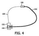
図4を参照すると、装置102の先端及び長さのレジストレーションの一例が、FORS(商標)システム104(図1)のための送出器具152と同じ位置にある測定器具150を使用することによって示されている。この実施形態では、ガイドワイヤ108は、オーバー・ザ・ワイヤ装置102を通って完全に延在する。オーバー・ザ・ワイヤ装置102は、ガイドワイヤ108に対して既知の位置を有する測定器具150に挿入される。装置102(例えば、カテーテル)の先端の位置が計算される。測定器具/特徴150は、形状検出ガイドワイヤ108の送出器具又は送出台に組み込まれてもよい。 Referring to FIG. 4, an example of tip and length registration of
説明される技術は、装置102の先端を識別するのに適している。例えば、ナビゲーションカテーテルを用いた多くの状況において、この情報は、装置102の臨床的に有意義な視覚化をオペレータに表示するのに必要な情報を十分に捕捉する。しかしながら、装置の長さが臨床関連ノードを完全に捕捉しない装置が多数存在する。これらの装置は、他にも例えば、バルーンカテーテル、エンドグラフト展開システム、バルブ展開システム、僧帽弁クリップ展開システム、ステントカテーテル、イメージング及び測定カテーテル(冠動脈内温度(ICT)、血管内超音波(IVUS)、冠血流予備量比(FFR)測定等)を含む。このような場合、先端位置は有用であるが、オーバー・ザ・ワイヤ装置102上の他の特徴/ノード位置は、より重要性が高くなり得る。例えば、EVARのためのエンドグラフト展開では、展開装置はガイドワイヤ上でナビゲートされ、大動脈内でアラインされる。エンドグラフトの保持リングは、腎動脈への分岐を妨げないように配置される必要がある。エンドグラフトが開窓を有する他の場合には、開窓が分岐血管と正確にアラインするように回転される必要もある。この例では、展開システムの先端は安全性に関してのみ関連しており、エンドグラフト自体の位置及び方向に関する何れの関連情報も含まない。このように、二次的又は異なるレジストレーション、例えばハブ106と臨床的に関連するノード(124)との間のレジストレーションが関連するようになる。 The technique described is suitable for identifying the tip of
このレジストレーションを実行する複数の方法がある。一例では、ノード(124)の位置は、視覚化ソフトウェア(図1の画像処理モジュール148)に直接入力されてもよい。これは、ノードが非常に再現性のある特定の装置(バルーンカテーテル)に適している。エンドグラフトなどの他の装置では、すべての装置においてエンドグラフトの制御位置はない。別の例では、X線下での装置の位置が使用されることはできる。ノード(124)は、放射線不透過性マーカーで示されてもよい。放射線不透過マーカーは、臨床医によって手動で識別されてもよく、自動的に識別されてもよく、又はその2つの組み合わせであってもよい。形状検出ガイドワイヤは、X線画像にレジストレーションされる必要がある。 X線(x、y)位置に最も近い形状ノードは、関連ノード(124)として用いられることができる。これは、プロシージャの前又はその間に行われることができる。さらに別の例では、代わりの術中イメージングモダリティが使用されることができる。モダリティは、X線の代わりに、例えば、コンピュータ断層撮影(CT)、磁気共鳴イメージング(MRI)、超音波などを含み得る。レジストレーションは、装置102の幅又は他の関連する特徴を測定するために実行されることもできる。 There are multiple ways to perform this registration. In one example, the location of the node (124) may be entered directly into the visualization software (
図5を参照すると、展開されていないステント202及び展開されているステント204が、一実施例によるオーバー・ザ・ワイヤ装置102上の関連ノード(例えば、図1のノード124)を識別するために使用され得る(放射線不透過性)マーカー208を示す矢印206で示される。 Referring to FIG. 5, the undeployed stent 202 and the deployed stent 204 are used to identify the associated node (eg,
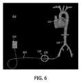
図6を参照すると、オーバー・ザ・ワイヤ装置102は、FORS(商標)システムを用いて視覚化されることができる。オーバー・ザ・ワイヤ装置102の可視化は、例えば血管/心臓232のイメージングモデル上に重ねられる特定の色及び厚さにおける装置の長さを示すことによって行われることができる。送出器具226から出てハブの湾曲部228を通過する形状検出ガイドワイヤ224のサンプル画像222が例示的に示されている。カテーテル102は、ガイドワイヤ224よりも太い線として示され、ハブ230の開始点からその既知の長さまで延在する。ガイドワイヤ224は、カテーテル102の先端をわずかに超えて延在する。各構成要素は、ディスプレイ118(図1)上のカテーテル102を視覚化するために、異なる色又はテクスチャで描かれている。(丸で囲まれる)ハブ230のモデルは、オペレータに基準のフレームを与えるために、カテーテル102に沿って示されてもよい。 With reference to FIG. 6, the over-the-
図7を参照すると、エンドグラフトの仮想表現が例示的に示されている。モデル250,252の位置及び方向は、オーバー・ザ・ワイヤ展開システムに沿ってターゲットノード(図示略)に結び付けられる。その位置及び方向は、形状検出ガイドワイヤ108を備えたハブを用いることによって知られる。一旦ターゲットノードがレジストレーションされ、識別されると、モデル250,252として表されるオーバー・ザ・ワイヤ装置の位置決めの間に、ユーザにガイドを与えるためにそれらはユーザに表示され得る。図7は、2つの例を示す。例240は、特徴モデル250を示し、例242は、エンドグラフトの物理モデル252を示す。モデル250は、上部保持リング254、開窓256、及びエンドグラフトの端部/底部258の位置などの、エンドグラフトの関連特徴を示す。展開されるエンドグラフトの物理モデル252が視覚化され、展開がその位置及び方向で実行される場合、医師が、エンドグラフトはどの位置に向くかを確認することが可能になる。モデル250,252の位置及び方向は、レジストレーションステップ中に決定される仮想カテーテル260上の何れかの関連する、選択されるターゲットノードにマッピングされる。 With reference to FIG. 7, a virtual representation of the endograft is illustrated. The positions and orientations of models 250,252 are tied to the target node (not shown) along the over-the-wire deployment system. Its position and orientation are known by using a hub with a shape
図8を参照すると、バルーンカテーテル270の仮想表現が、別の例による血管272内において例示的に示されている。バルーン位置は、オーバー・ザ・ワイヤ展開システムに沿ってターゲットノードに結び付けられる。この位置は、形状検出ガイドワイヤを備えるハブを使用することによって知られる。バルーンカテーテル270のモデルは、単一の形状ノードにマッピングされるのではなく、ファイバに沿った一連の形状ノードにマッピングされる。これにより、モデル、この場合バルーンは、装置の現在の形状に従って変形される。 With reference to FIG. 8, a hypothetical representation of the
装置の視覚化のために記述されているモデルは、多くの形態を取ることができる。これらは、アンカーポイント、開窓、又は放射線不透過性マーカーの位置などの関連する特徴を含むことができる装置の予測モデルを含むことができる。装置のモデルはデータベースから取得されることができ、選択されるモデルはユーザによって調整され得る(未展開、部分的展開、完全展開など)。術中イメージング(例えば、蛍光透視法、XPER CT(商標)、バイプレーン蛍光透視法、超音波など)によって生成される装置の2D又は3D表現が示される。このモデルは、利用可能な何れかの時点でライブ解剖学的イメージングを使用して更新されることができる。本原理は、形状検出ガイドワイヤ上を実行される装置を用いて説明されてきたが、本原理は、形状検出装置としてのガイドワイヤに限定されない。それは、他のツールの形状を推測するために使用される、形状検出ファイバを備えた何れかのツールとしてより広く言及されることができる。取り付け可能なハブの使用は、形状検出が可能ではないが、形状検出ツールと共に使用されている装置の視覚的形状表現を通じて、形状検出ガイドワイヤ又はツールの形状変形を引き起こすように提供される。これにより、何れかの商用カテーテル(手動又はロボット)、展開システム、シース又は他のそのような装置が形状検出ガイドワイヤ(又は他の器具)を使用してナビゲートされることが可能になる。これは、例えば脈管(カテーテル、シース、展開システムなど)、管腔内(内視鏡)、整形外科(kワイヤ及びスクリュードライバー)ならびに非医療用途などの複数の有用な用途に適用されることができ、このような装置の手動操作とロボット操作との両方にも適用される。 The models described for device visualization can take many forms. These can include predictive models of the device that can include related features such as anchor points, fenestrations, or the location of radiation opaque markers. The model of the device can be retrieved from the database and the selected model can be adjusted by the user (unexpanded, partially expanded, fully expanded, etc.). A 2D or 3D representation of the device produced by intraoperative imaging (eg, fluorescence perspective, XPER CT ™, biplane fluorescence perspective, ultrasound, etc.) is shown. This model can be updated using live anatomical imaging at any time available. Although this principle has been described using a device running on a shape detection guidewire, the principle is not limited to the guidewire as a shape detection device. It can be more broadly referred to as any tool with shape detection fibers used to infer the shape of other tools. The use of attachable hubs is not capable of shape detection, but is provided to cause shape deformation of the shape detection guidewire or tool through the visual shape representation of the device used with the shape detection tool. This allows any commercial catheter (manual or robotic), deployment system, sheath or other such device to be navigated using shape detection guidewires (or other instruments). This applies to multiple useful applications such as vessels (catheter, sheath, deployment system, etc.), intraluminal (endoscope), orthopedics (k-wire and screwdriver) and non-medical applications. It can be applied to both manual operation of such devices and robot operation.
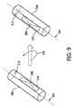
図9を参照すると、近位ハブアタッチメント306が、装置(図示略)の遠位部分の方向を決定するために示されている。ハブ306は、それを通過する形状検出ガイドワイヤ304を既知の形状に偏向させる形状プロファイル308を含む。その形状は、ハブ306に結合される、カテーテル、エンドグラフト展開システムなどのオーバー・ザ・ワイヤ装置とガイドワイヤ304との間の長手方向レジストレーションを決定するために、形状検出ガイドワイヤ304の光ファイバに沿って検出されることができる。ハブ306はオーバー・ザ・ワイヤ装置に結合されているので、ハブ形状は、オーバー・ザ・ワイヤ装置の近位部分に加えられる回転をトラッキングするために使用されることもできる。 With reference to FIG. 9, the
一実施形態では、ハブ306の回転(したがって装置全体)は、ハブ306内部の既知の形状プロファイル308に平面310を適合させ、その平面310の方向を経時的にトラッキングすることによって測定されることができる。形状プロファイル308は、好ましくは縦軸に対して軸を外れた2D又は3D形状を含むことができる。視覚的基準点312は、画像における視覚化、及び/又はオーバー・ザ・ワイヤ装置に対するハブ306の位置決めのために使用され得る。 In one embodiment, the rotation of the hub 306 (and thus the entire device) may be measured by adapting the
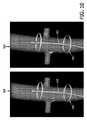
図10を参照すると、有窓のエンドグラフトのモデル350は回転させられて、エンドグラフトの開窓を解剖学的モデル352により良好にアラインされる。自体の周りのハブ形状の回転は、遠位部分内にハブ306を含む、エンドグラフトモデル350の回転をマッピングするために使用される。 With reference to FIG. 10, the fenestrated end-
図9及び10を参照すると、図10の遠位仮想モデル350の方向は、図9に示されるハブ306の反時計回りの回転356に後続する。ハブ306の同じ反時計回りの回転は、平面310を既知の形状に適合させ、時間の経過とともに平面310の方向をトラッキングすることによって測定されることができる。代わりの実施形態では、ハブ306内の形状は、図9に示されるように、3次元であり、プレーナではない。このような実施形態では、3D形状の方向は、当業者に知られているレジストレーション技術によって経時的にトラッキングされる。 With reference to FIGS. 9 and 10, the orientation of the distal
オーバー・ザ・ワイヤ装置(エンドグラフトなど)のトルク特性は、ハブ306のトルクを、装置の遠位ノード又は遠位部分のトルクにマッピングするために使用されることができる。エンドグラフト展開システムのような多くの治療装置では、これはほぼ1対1の関係になる。ナビゲーションカテーテルのような他の装置では、これは1対1の関係ではなく、トルク特性は装置の形状及び装置の特性に大きく依存する。このような状況では、モデルは、装置形状、ハブの方向、及び装置特性の既知の情報を使用することによって、近位セクションの予想される方向を予測するために使用されることができる。 The torque characteristics of an over-the-wire device (such as an end graft) can be used to map the torque of the
イメージングは、この技術を補完するために使用されることができる。装置の近位部分の方向とハブの方向との間の初期レジストレーションは、X線、超音波、CT、MRIなどを用いた画像ベースレジストレーションを使用して行われることができる。装置の遠位部分の周期的なイメージングは、モデル又は装置の予測される方向を更新するために使用される。 1つ又は複数の投影は使用されることができる。ユーザ入力は、予測される方向を更新するために使用されることもできる。代わりに、ハブ306は、ハブ306が取り付けられるとすぐにレジストレーションが既に知られているように、反復可能な態様で装置に取り付けられることができる。 Imaging can be used to complement this technique. Initial registration between the orientation of the proximal portion of the device and the orientation of the hub can be done using image-based registration using X-rays, ultrasound, CT, MRI, and the like. Periodic imaging of the distal portion of the device is used to update the model or the predicted orientation of the device. One or more projections can be used. User input can also be used to update the predicted direction. Alternatively, the
複雑な解剖学的構造では、ユーザが、頭の中で近位ハブの回転方向を所望の遠位回転にマッピングすることは難しいかもしれない。一実施形態では、ユーザは、(例えば、術前又は術中のイメージングによって生成される)解剖学的構造のモデル上にターゲットを配置されることができる。これらのターゲットは、展開又は配向されるべき装置の特定の特徴にマッピングされる。画像処理モジュール148(図1)の視覚化ソフトウェアは、装置の現在位置と装置のターゲット位置との間の回転角を決定し、それから、ハブ306をどれだけ回転させ、どの方向に回転させるかをユーザに知らせることができる。この計算は、それが1対1でない場合、既知のトルクマッピングを考慮に入れることもできる。この特徴は、特有のドライブの必要性を有する操縦可能なロボットカテーテルに特に有用であり得る。 With complex anatomy, it may be difficult for the user to map the direction of rotation of the proximal hub in the head to the desired distal rotation. In one embodiment, the user can place the target on a model of anatomical structure (eg, generated by preoperative or intraoperative imaging). These targets are mapped to specific features of the device to be deployed or oriented. The visualization software in image processing module 148 (Figure 1) determines the angle of rotation between the current position of the device and the target position of the device, and then how much and in what direction the
図11を参照すると、ブロック/フロー図は、一実施形態によるオーバー・ザ・ワイヤ装置配置中のハブからの配向を使用するためのワークフローを示す。ブロック402において、ハブは、オーバー・ザ・ワイヤ装置に取り付けられる。ハブは、オーバー・ザ・ワイヤ装置に直接接続されてもよく、オーバー・ザ・ワイヤ装置に一体的に形成されてもよい。ハブは、オーバー・ザ・ワイヤ装置と共に並進して回転する必要がある。一実施形態では、ルアーロックタイプのハブを使用する場合、ハブは、ねじり剛性のある態様でオーバー・ザ・ワイヤ装置に結合される更なる特徴を有してもよく、したがってそのような作用が望ましくないときにルアー接続を緩めることが回避される。 With reference to FIG. 11, the block / flow diagram shows a workflow for using orientation from a hub during an over-the-wire device arrangement according to one embodiment. At
ブロック404において、ハブの方向は、オーバー・ザ・ワイヤ装置上のターゲット特徴(又は複数の特徴)にレジストレーションされる。ハブ上の基準点又は特徴は、オーバー・ザ・ワイヤ装置上のノード又は特徴と一致するか又はアラインされる。これは、異なるオーバー・ザ・ワイヤ装置に対して異なる物理的特徴を含む。例えば、ハブを使用してオーバー・ザ・ワイヤ装置の回転アライメントを補助するために追加されることができる受動的な特徴は、固有の回転位置を識別するためにハブ上のドット又は隆起した溝を含むことができる。これらの特徴は、例えば、エンドグラフト回転、カテーテル遠位部分、遠位部分に沿った特定のノードなどを含み得るか、又はこれに関連し得る。 At
ブロック406において、オーバー・ザ・ワイヤ装置は、形状検出ガイドワイヤ上でナビゲートされる。形状検出ガイドワイヤ又は他の器具は、ハブを通過し、ハブによって成形される。ハブは、今度はオーバー・ザ・ワイヤ装置に結合される。ブロック408において、ターゲット特徴の動きが解剖学的マップ上に表示される。ブロック408において、ターゲット特徴の位置は、ユーザ入力、イメージング(例えば、術中イメージング)を使用して、モデルなどを使用して精緻化される。パスは、オーバー・ザ・ワイヤに対して所望の位置が達成されるまで、ブロック406にループバックされる。非治療的測定装置の場合、測定時の既知の方向は、回転画像又は測定値を共にスティッチするのを支援することができる。 At
添付の特許請求の範囲を解釈する際には、以下が理解されるべきである。
a)「含む(comprising)」という単語は、所与の請求項に列挙されるもの以外の要素又は行為の存在を排除するものではない。
b)要素に先行する単語「a」又は「an」は、複数のそのような要素の存在を排除しない。
c)請求項中のいかなる参照符号もその範囲を限定するものではない。
d)いくつかの「手段」は、同一のアイテム、ハードウェア又はソフトウェア実装の構造又は機能によって表されてもよい。
e)具体的な指示がない限り、特定の一連の行為は要求されないものとする。In interpreting the appended claims, the following should be understood:
a) The word "comprising" does not preclude the existence of any element or act other than those listed in a given claim.
b) The word "a" or "an" preceding an element does not preclude the existence of more than one such element.
c) No reference code in the claims limits its scope.
d) Some "means" may be represented by the structure or function of the same item, hardware or software implementation.
e) No specific sequence of actions is required unless specifically instructed.
光学形状検出ガイドワイヤ(例示的であって限定的ではない)を備えた装置配向用のハブの好ましい実施形態について説明したが、上述の教示に照らして当業者によって修正及び変形が可能であることに留意される。 したがって、開示される特許請求の範囲に記載される本明細書に開示される実施形態の範囲内にある開示される開示の特定の実施形態において変更がなされ得ることが理解されるべきである。 特許法によって要求される詳細及び特殊性をこのように記載したので、特許請求の範囲に記載され、特許請求されているものは、添付の特許請求の範囲に記載されている。 Preferred embodiments of hubs for device orientation with optical shape detection guide wires (exemplary and not limited) have been described, but can be modified and modified by one of ordinary skill in the art in light of the above teachings. Be noted. Therefore, it should be understood that changes may be made in certain embodiments of the disclosed disclosure that are within the scope of the embodiments disclosed herein as described in the disclosed claims. Since the details and peculiarities required by the Patent Law are described in this way, what is described in the claims and what is claimed is described in the attached claims.
Claims (15)
Translated fromJapanese細長い可撓性器具と、
前記可撓性器具に結合される形状検出システムと、
内部に前記形状検出システムを備える前記可撓性器具を長手方向に受け入れて維持するように構成されるプロファイルを含むハブであって、前記プロファイルは、前記形状検出システムを使用して基準位置に対する前記ハブの位置及び回転をトラッキングするように構成され、前記ハブは、前記ハブの位置及び回転の変化が展開可能な装置における対応する変化を示すように、前記展開可能な装置の近位部分に長手方向に結合されるように構成される、ハブと
を有する、システム。A system for deploying equipment
Elongated flexible equipment and
A shape detection system coupled to the flexible device and
A hub comprising a profile configured to internally accept and maintain the flexible device comprising the shape detection system, wherein the profile is said to be relative to a reference position using the shape detection system. is configured to trackthe positionandrotation of the hub, said hub, said to exhibit a corresponding change in the positionandrotation changes are expandable device of the hub, a proximal portion of the deployable device A system with a hub that is configured to be longitudinally coupled to.
形状検出可能なガイドワイヤと、
内部に前記形状検出可能なガイドワイヤを長手方向に受け入れて維持するように構成されるプロファイルを含むハブであって、前記プロファイルは、形状検出を使用して基準位置に対する前記ハブの位置及び回転の識別を可能にする形状を含む、ハブと、
前記ガイドワイヤ上での展開中に前記ハブに長手方向に接続可能な近位部分を持つオーバー・ザ・ワイヤ装置と、
前記ハブの位置及び回転に従って前記オーバー・ザ・ワイヤ装置の位置及び回転を推測するために前記形状検出を使用して識別される前記ハブの位置と解剖学的画像とをレジストレーションするレジストレーションモジュールと
を有する、システム。A system for deploying equipment
A guide wire that can detect the shape and
The shape detectable guidewire inside a hub comprising a configured profile to maintain accepted in the longitudinal direction, and the profile, positionandrotation of the hub relative to the reference position using the shape detection comprises a shape that allows forthe identification, and the hub,
An over-the-wire device with a proximal portion that can be longitudinally connected to the hub during deployment on the guide wire.
Resist registrationand anatomic imageand the position of the hubto be identified using the shape detectingthe positionandrotation thus to infer the positionand rotation of the over-the-wire device of the hub A system with a rotation module.
Applications Claiming Priority (3)
| Application Number | Priority Date | Filing Date | Title |
|---|---|---|---|
| US201562236180P | 2015-10-02 | 2015-10-02 | |
| US62/236,180 | 2015-10-02 | ||
| PCT/IB2016/055341WO2017055950A1 (en) | 2015-10-02 | 2016-09-08 | Hub for device placement with optical shape sensed guidewire |
Publications (3)
| Publication Number | Publication Date |
|---|---|
| JP2018537143A JP2018537143A (en) | 2018-12-20 |
| JP2018537143A5 JP2018537143A5 (en) | 2019-09-26 |
| JP6902533B2true JP6902533B2 (en) | 2021-07-14 |
Family
ID=57113513
Family Applications (1)
| Application Number | Title | Priority Date | Filing Date |
|---|---|---|---|
| JP2018516149AActiveJP6902533B2 (en) | 2015-10-02 | 2016-09-08 | Hub for device placement with shape detection system |
Country Status (5)
| Country | Link |
|---|---|
| US (1) | US10994095B2 (en) |
| EP (1) | EP3355779A1 (en) |
| JP (1) | JP6902533B2 (en) |
| CN (1) | CN108135531B (en) |
| WO (1) | WO2017055950A1 (en) |
Families Citing this family (32)
| Publication number | Priority date | Publication date | Assignee | Title |
|---|---|---|---|---|
| CN108472082B (en)* | 2015-12-29 | 2021-08-10 | 皇家飞利浦有限公司 | Registration system for medical navigation and method of operation thereof |
| EP3606592B1 (en)* | 2017-04-07 | 2025-01-08 | Bard Access Systems, Inc. | Optical fiber-based medical device tracking and monitoring system |
| CN108959762A (en)* | 2018-06-29 | 2018-12-07 | 江铃汽车股份有限公司 | A kind of efficient bushing approximating method |
| US20200121286A1 (en)* | 2018-10-19 | 2020-04-23 | Boston Scientific Scimed, Inc. | Systems, catheters, drive units, and methods for automatic catheter identification |
| EP4013338A4 (en) | 2019-08-12 | 2023-08-30 | Bard Access Systems, Inc. | SHAPE DETECTION SYSTEMS AND METHODS FOR MEDICAL DEVICES |
| CN114727846A (en)* | 2019-10-17 | 2022-07-08 | 皇家飞利浦有限公司 | Automatic OSS-based feature detection and device characterization |
| CN112826497B (en) | 2019-11-25 | 2025-09-09 | 巴德阿克塞斯系统股份有限公司 | Optical tip tracking system and method thereof |
| EP4061272A4 (en) | 2019-11-25 | 2023-11-22 | Bard Access Systems, Inc. | Shape-sensing systems with filters and methods thereof |
| US11474310B2 (en) | 2020-02-28 | 2022-10-18 | Bard Access Systems, Inc. | Optical connection systems and methods thereof |
| CN215461207U (en) | 2020-02-28 | 2022-01-11 | 巴德阿克塞斯系统股份有限公司 | Catheter and medical instrument monitoring system |
| CN113332561A (en) | 2020-03-03 | 2021-09-03 | 巴德阿克塞斯系统股份有限公司 | System and method for optical shape sensing and electrical signal conduction |
| WO2021202589A1 (en) | 2020-03-30 | 2021-10-07 | Bard Access Systems, Inc. | Optical and electrical diagnostic systems and methods thereof |
| CN113842536A (en) | 2020-06-26 | 2021-12-28 | 巴德阿克塞斯系统股份有限公司 | Dislocation detection system |
| WO2022005870A1 (en) | 2020-06-29 | 2022-01-06 | Bard Access Systems, Inc. | Automatic dimensional frame reference for fiber optic |
| WO2022011287A1 (en) | 2020-07-10 | 2022-01-13 | Bard Access Systems, Inc. | Continuous fiber optic functionality monitoring and self-diagnostic reporting system |
| WO2022031613A1 (en) | 2020-08-03 | 2022-02-10 | Bard Access Systems, Inc. | Bragg grated fiber optic fluctuation sensing and monitoring system |
| WO2022048984A1 (en)* | 2020-09-02 | 2022-03-10 | Koninklijke Philips N.V. | Medical intervention control based on device type identification |
| CN114246583A (en) | 2020-09-25 | 2022-03-29 | 巴德阿克塞斯系统股份有限公司 | Fiber Optic Oximetry Systems for Detection and Confirmation |
| CN114344514A (en) | 2020-10-13 | 2022-04-15 | 巴德阿克塞斯系统股份有限公司 | Disinfection enclosure for fiber optic connectors and method thereof |
| WO2022081723A1 (en)* | 2020-10-13 | 2022-04-21 | Bard Access Systems, Inc. | Fiber optic enabled deployable medical devices for monitoring, assessment and capture of deployment information |
| CN114518075A (en) | 2020-11-18 | 2022-05-20 | 巴德阿克塞斯系统股份有限公司 | fiber optic stylet holder |
| WO2022115624A1 (en) | 2020-11-24 | 2022-06-02 | Bard Access Systems, Inc. | Steerable fiber optic shape sensing enabled elongated medical instrument |
| WO2022150411A1 (en) | 2021-01-06 | 2022-07-14 | Bard Access Systems, Inc. | Needle guidance using fiber optic shape sensing |
| US12426954B2 (en) | 2021-01-26 | 2025-09-30 | Bard Access Systems, Inc. | Fiber optic shape sensing system associated with port placement |
| EP4154810A1 (en) | 2021-09-28 | 2023-03-29 | Koninklijke Philips N.V. | System and device control using shape clustering |
| EP4366613A1 (en) | 2021-07-08 | 2024-05-15 | Koninklijke Philips N.V. | System and device control using shape clustering |
| US12419694B2 (en) | 2021-10-25 | 2025-09-23 | Bard Access Systems, Inc. | Reference plane for medical device placement |
| US12318149B2 (en) | 2022-03-08 | 2025-06-03 | Bard Access Systems, Inc. | Medical shape sensing devices and systems |
| US12426956B2 (en) | 2022-03-16 | 2025-09-30 | Bard Access Systems, Inc. | Medical system and method for monitoring medical device insertion and illumination patterns |
| US12089815B2 (en) | 2022-03-17 | 2024-09-17 | Bard Access Systems, Inc. | Fiber optic medical systems and devices with atraumatic tip |
| US12343117B2 (en) | 2022-06-28 | 2025-07-01 | Bard Access Systems, Inc. | Fiber optic medical systems and methods for identifying blood vessels |
| US12349984B2 (en) | 2022-06-29 | 2025-07-08 | Bard Access Systems, Inc. | System, method, and apparatus for improved confirm of an anatomical position of a medical instrument |
Family Cites Families (16)
| Publication number | Priority date | Publication date | Assignee | Title |
|---|---|---|---|---|
| US6053913A (en) | 1998-09-10 | 2000-04-25 | Tu; Lily Chen | Rapid exchange stented balloon catheter having ablation capabilities |
| EP2363073B1 (en)* | 2005-08-01 | 2015-10-07 | St. Jude Medical Luxembourg Holding S.à.r.l. | Medical apparatus system having optical fiber load sensing capability |
| US20080140180A1 (en) | 2006-12-07 | 2008-06-12 | Medtronic Vascular, Inc. | Vascular Position Locating Apparatus and Method |
| US8728097B1 (en) | 2008-02-26 | 2014-05-20 | Mitralign, Inc. | Tissue plication devices and methods for their use |
| US8957367B2 (en)* | 2009-11-13 | 2015-02-17 | Intuitive Surgical Operations, Inc. | Shape sensor contained in a link of a kinematic chain with at least one pre-set perturbation and method to sense relative partial-pose information using the shape sensor |
| US9285246B2 (en)* | 2010-02-12 | 2016-03-15 | Intuitive Surgical Operations, Inc. | Method and system for absolute three-dimensional measurements using a twist-insensitive shape sensor |
| BR112013004528A2 (en) | 2010-09-01 | 2016-06-07 | Koninkl Philips Electronics Nv | optical guidewire system and method for advancing a catheter to a target region relative to a distal end of an optical guidewire |
| US20120071752A1 (en) | 2010-09-17 | 2012-03-22 | Sewell Christopher M | User interface and method for operating a robotic medical system |
| JP6270483B2 (en)* | 2011-01-28 | 2018-01-31 | コーニンクレッカ フィリップス エヌ ヴェKoninklijke Philips N.V. | 3D shape reconstruction for optical tracking of elongated devices |
| BR112013021042B1 (en) | 2011-02-18 | 2021-08-17 | DePuy Synthes Products, LLC | MANUAL TOOL |
| JP6334517B2 (en)* | 2012-05-14 | 2018-05-30 | インテュイティブ サージカル オペレーションズ, インコーポレイテッド | System and method for deformation compensation using shape sensing |
| CN104968390B (en) | 2012-12-06 | 2019-04-23 | 印第安维尔斯医疗公司 | Steerable guide wire and method of use |
| US20140277091A1 (en) | 2013-03-14 | 2014-09-18 | Cook Medical Technologies Llc | Detachable delivery device |
| CN105593731B (en)* | 2013-09-30 | 2017-12-05 | 皇家飞利浦有限公司 | Start Fixtures for Optical Shape Sensing |
| EP3055646B1 (en)* | 2013-10-02 | 2020-12-16 | Koninklijke Philips N.V. | Device tracking using longitudinal encoding |
| CN105592790A (en)* | 2013-10-02 | 2016-05-18 | 皇家飞利浦有限公司 | Hub design and methods for optical shape sensing registration |
- 2016
- 2016-09-08JPJP2018516149Apatent/JP6902533B2/enactiveActive
- 2016-09-08USUS15/761,902patent/US10994095B2/enactiveActive
- 2016-09-08WOPCT/IB2016/055341patent/WO2017055950A1/ennot_activeCeased
- 2016-09-08EPEP16778455.2Apatent/EP3355779A1/ennot_activeWithdrawn
- 2016-09-08CNCN201680057537.9Apatent/CN108135531B/enactiveActive
Also Published As
| Publication number | Publication date |
|---|---|
| US10994095B2 (en) | 2021-05-04 |
| US20180264227A1 (en) | 2018-09-20 |
| WO2017055950A1 (en) | 2017-04-06 |
| CN108135531B (en) | 2021-06-29 |
| EP3355779A1 (en) | 2018-08-08 |
| JP2018537143A (en) | 2018-12-20 |
| CN108135531A (en) | 2018-06-08 |
Similar Documents
| Publication | Publication Date | Title |
|---|---|---|
| JP6902533B2 (en) | Hub for device placement with shape detection system | |
| CN108135530B (en) | A hub for device navigation utilizing optical shape-sensing guidewires | |
| US11547489B2 (en) | Shape sensing of multiple over-the-wire devices | |
| EP2866642B1 (en) | Fiber optic sensor guided navigation for vascular visualization and monitoring | |
| US20230000567A1 (en) | Device visualization through optical shape sensing of a guidewire | |
| JP6734282B2 (en) | Visualization of endografts with pre-incorporated or removable optical shape sensing attachments | |
| JP6794361B2 (en) | Visualization of end grafts by optical shape detection | |
| JP2014526927A (en) | Curved multiplanar reconstruction using optical fiber shape data | |
| JP7059247B6 (en) | Balloon catheter containing shape-sensing optical fiber |
Legal Events
| Date | Code | Title | Description |
|---|---|---|---|
| A521 | Request for written amendment filed | Free format text:JAPANESE INTERMEDIATE CODE: A523 Effective date:20190814 | |
| A621 | Written request for application examination | Free format text:JAPANESE INTERMEDIATE CODE: A621 Effective date:20190814 | |
| A977 | Report on retrieval | Free format text:JAPANESE INTERMEDIATE CODE: A971007 Effective date:20200731 | |
| A131 | Notification of reasons for refusal | Free format text:JAPANESE INTERMEDIATE CODE: A131 Effective date:20200903 | |
| A521 | Request for written amendment filed | Free format text:JAPANESE INTERMEDIATE CODE: A523 Effective date:20201203 | |
| TRDD | Decision of grant or rejection written | ||
| A01 | Written decision to grant a patent or to grant a registration (utility model) | Free format text:JAPANESE INTERMEDIATE CODE: A01 Effective date:20210603 | |
| A61 | First payment of annual fees (during grant procedure) | Free format text:JAPANESE INTERMEDIATE CODE: A61 Effective date:20210621 | |
| R150 | Certificate of patent or registration of utility model | Ref document number:6902533 Country of ref document:JP Free format text:JAPANESE INTERMEDIATE CODE: R150 | |
| R250 | Receipt of annual fees | Free format text:JAPANESE INTERMEDIATE CODE: R250 | |
| R250 | Receipt of annual fees | Free format text:JAPANESE INTERMEDIATE CODE: R250 |