JP6901205B2 - Electrosurgical equipment - Google Patents
Electrosurgical equipmentDownload PDFInfo
- Publication number
- JP6901205B2 JP6901205B2JP2017002904AJP2017002904AJP6901205B2JP 6901205 B2JP6901205 B2JP 6901205B2JP 2017002904 AJP2017002904 AJP 2017002904AJP 2017002904 AJP2017002904 AJP 2017002904AJP 6901205 B2JP6901205 B2JP 6901205B2
- Authority
- JP
- Japan
- Prior art keywords
- surgical instrument
- blade
- instrument according
- shaft
- distal end
- Prior art date
- Legal status (The legal status is an assumption and is not a legal conclusion. Google has not performed a legal analysis and makes no representation as to the accuracy of the status listed.)
- Active
Links
Images


Classifications
- A—HUMAN NECESSITIES
- A61—MEDICAL OR VETERINARY SCIENCE; HYGIENE
- A61B—DIAGNOSIS; SURGERY; IDENTIFICATION
- A61B18/00—Surgical instruments, devices or methods for transferring non-mechanical forms of energy to or from the body
- A61B18/04—Surgical instruments, devices or methods for transferring non-mechanical forms of energy to or from the body by heating
- A61B18/12—Surgical instruments, devices or methods for transferring non-mechanical forms of energy to or from the body by heating by passing a current through the tissue to be heated, e.g. high-frequency current
- A61B18/14—Probes or electrodes therefor
- A61B18/1442—Probes having pivoting end effectors, e.g. forceps
- A61B18/1445—Probes having pivoting end effectors, e.g. forceps at the distal end of a shaft, e.g. forceps or scissors at the end of a rigid rod
- A—HUMAN NECESSITIES
- A61—MEDICAL OR VETERINARY SCIENCE; HYGIENE
- A61B—DIAGNOSIS; SURGERY; IDENTIFICATION
- A61B17/00—Surgical instruments, devices or methods
- A61B17/28—Surgical forceps
- A61B17/29—Forceps for use in minimally invasive surgery
- A—HUMAN NECESSITIES
- A61—MEDICAL OR VETERINARY SCIENCE; HYGIENE
- A61B—DIAGNOSIS; SURGERY; IDENTIFICATION
- A61B17/00—Surgical instruments, devices or methods
- A61B17/28—Surgical forceps
- A61B17/29—Forceps for use in minimally invasive surgery
- A61B17/2909—Handles
- A—HUMAN NECESSITIES
- A61—MEDICAL OR VETERINARY SCIENCE; HYGIENE
- A61B—DIAGNOSIS; SURGERY; IDENTIFICATION
- A61B18/00—Surgical instruments, devices or methods for transferring non-mechanical forms of energy to or from the body
- A61B18/04—Surgical instruments, devices or methods for transferring non-mechanical forms of energy to or from the body by heating
- A61B18/12—Surgical instruments, devices or methods for transferring non-mechanical forms of energy to or from the body by heating by passing a current through the tissue to be heated, e.g. high-frequency current
- A61B18/14—Probes or electrodes therefor
- A61B18/1482—Probes or electrodes therefor having a long rigid shaft for accessing the inner body transcutaneously in minimal invasive surgery, e.g. laparoscopy
- A—HUMAN NECESSITIES
- A61—MEDICAL OR VETERINARY SCIENCE; HYGIENE
- A61B—DIAGNOSIS; SURGERY; IDENTIFICATION
- A61B17/00—Surgical instruments, devices or methods
- A61B17/28—Surgical forceps
- A61B17/29—Forceps for use in minimally invasive surgery
- A61B17/295—Forceps for use in minimally invasive surgery combined with cutting implements
- A—HUMAN NECESSITIES
- A61—MEDICAL OR VETERINARY SCIENCE; HYGIENE
- A61B—DIAGNOSIS; SURGERY; IDENTIFICATION
- A61B18/00—Surgical instruments, devices or methods for transferring non-mechanical forms of energy to or from the body
- A—HUMAN NECESSITIES
- A61—MEDICAL OR VETERINARY SCIENCE; HYGIENE
- A61B—DIAGNOSIS; SURGERY; IDENTIFICATION
- A61B18/00—Surgical instruments, devices or methods for transferring non-mechanical forms of energy to or from the body
- A61B18/04—Surgical instruments, devices or methods for transferring non-mechanical forms of energy to or from the body by heating
- A61B18/12—Surgical instruments, devices or methods for transferring non-mechanical forms of energy to or from the body by heating by passing a current through the tissue to be heated, e.g. high-frequency current
- A61B18/14—Probes or electrodes therefor
- A61B18/1442—Probes having pivoting end effectors, e.g. forceps
- A—HUMAN NECESSITIES
- A61—MEDICAL OR VETERINARY SCIENCE; HYGIENE
- A61B—DIAGNOSIS; SURGERY; IDENTIFICATION
- A61B17/00—Surgical instruments, devices or methods
- A61B2017/00017—Electrical control of surgical instruments
- A—HUMAN NECESSITIES
- A61—MEDICAL OR VETERINARY SCIENCE; HYGIENE
- A61B—DIAGNOSIS; SURGERY; IDENTIFICATION
- A61B17/00—Surgical instruments, devices or methods
- A61B2017/00367—Details of actuation of instruments, e.g. relations between pushing buttons, or the like, and activation of the tool, working tip, or the like
- A61B2017/00371—Multiple actuation, e.g. pushing of two buttons, or two working tips becoming operational
- A—HUMAN NECESSITIES
- A61—MEDICAL OR VETERINARY SCIENCE; HYGIENE
- A61B—DIAGNOSIS; SURGERY; IDENTIFICATION
- A61B17/00—Surgical instruments, devices or methods
- A61B17/28—Surgical forceps
- A61B17/29—Forceps for use in minimally invasive surgery
- A61B2017/2901—Details of shaft
- A61B2017/2902—Details of shaft characterized by features of the actuating rod
- A61B2017/2903—Details of shaft characterized by features of the actuating rod transferring rotary motion
- A—HUMAN NECESSITIES
- A61—MEDICAL OR VETERINARY SCIENCE; HYGIENE
- A61B—DIAGNOSIS; SURGERY; IDENTIFICATION
- A61B17/00—Surgical instruments, devices or methods
- A61B17/28—Surgical forceps
- A61B17/29—Forceps for use in minimally invasive surgery
- A61B17/2909—Handles
- A61B2017/2912—Handles transmission of forces to actuating rod or piston
- A61B2017/2913—Handles transmission of forces to actuating rod or piston cams or guiding means
- A—HUMAN NECESSITIES
- A61—MEDICAL OR VETERINARY SCIENCE; HYGIENE
- A61B—DIAGNOSIS; SURGERY; IDENTIFICATION
- A61B17/00—Surgical instruments, devices or methods
- A61B17/28—Surgical forceps
- A61B17/29—Forceps for use in minimally invasive surgery
- A61B17/2909—Handles
- A61B2017/2912—Handles transmission of forces to actuating rod or piston
- A61B2017/2919—Handles transmission of forces to actuating rod or piston details of linkages or pivot points
- A61B2017/292—Handles transmission of forces to actuating rod or piston details of linkages or pivot points connection of actuating rod to handle, e.g. ball end in recess
- A—HUMAN NECESSITIES
- A61—MEDICAL OR VETERINARY SCIENCE; HYGIENE
- A61B—DIAGNOSIS; SURGERY; IDENTIFICATION
- A61B17/00—Surgical instruments, devices or methods
- A61B17/28—Surgical forceps
- A61B17/29—Forceps for use in minimally invasive surgery
- A61B2017/2926—Details of heads or jaws
- A61B2017/2927—Details of heads or jaws the angular position of the head being adjustable with respect to the shaft
- A61B2017/2929—Details of heads or jaws the angular position of the head being adjustable with respect to the shaft with a head rotatable about the longitudinal axis of the shaft
- A61B2017/293—Details of heads or jaws the angular position of the head being adjustable with respect to the shaft with a head rotatable about the longitudinal axis of the shaft with means preventing relative rotation between the shaft and the actuating rod
- A—HUMAN NECESSITIES
- A61—MEDICAL OR VETERINARY SCIENCE; HYGIENE
- A61B—DIAGNOSIS; SURGERY; IDENTIFICATION
- A61B17/00—Surgical instruments, devices or methods
- A61B17/28—Surgical forceps
- A61B17/29—Forceps for use in minimally invasive surgery
- A61B2017/2926—Details of heads or jaws
- A61B2017/2932—Transmission of forces to jaw members
- A—HUMAN NECESSITIES
- A61—MEDICAL OR VETERINARY SCIENCE; HYGIENE
- A61B—DIAGNOSIS; SURGERY; IDENTIFICATION
- A61B17/00—Surgical instruments, devices or methods
- A61B17/28—Surgical forceps
- A61B17/29—Forceps for use in minimally invasive surgery
- A61B2017/2926—Details of heads or jaws
- A61B2017/2945—Curved jaws
- A—HUMAN NECESSITIES
- A61—MEDICAL OR VETERINARY SCIENCE; HYGIENE
- A61B—DIAGNOSIS; SURGERY; IDENTIFICATION
- A61B17/00—Surgical instruments, devices or methods
- A61B17/28—Surgical forceps
- A61B17/29—Forceps for use in minimally invasive surgery
- A61B2017/2946—Locking means
- A—HUMAN NECESSITIES
- A61—MEDICAL OR VETERINARY SCIENCE; HYGIENE
- A61B—DIAGNOSIS; SURGERY; IDENTIFICATION
- A61B17/00—Surgical instruments, devices or methods
- A61B17/28—Surgical forceps
- A61B17/29—Forceps for use in minimally invasive surgery
- A61B2017/2948—Sealing means, e.g. for sealing the interior from fluid entry
- A—HUMAN NECESSITIES
- A61—MEDICAL OR VETERINARY SCIENCE; HYGIENE
- A61B—DIAGNOSIS; SURGERY; IDENTIFICATION
- A61B17/00—Surgical instruments, devices or methods
- A61B17/32—Surgical cutting instruments
- A61B17/3209—Incision instruments
- A61B17/3211—Surgical scalpels, knives; Accessories therefor
- A61B2017/32113—Surgical scalpels, knives; Accessories therefor with extendable or retractable guard or blade
- A—HUMAN NECESSITIES
- A61—MEDICAL OR VETERINARY SCIENCE; HYGIENE
- A61B—DIAGNOSIS; SURGERY; IDENTIFICATION
- A61B18/00—Surgical instruments, devices or methods for transferring non-mechanical forms of energy to or from the body
- A61B2018/00053—Mechanical features of the instrument of device
- A61B2018/00059—Material properties
- A61B2018/00071—Electrical conductivity
- A61B2018/00083—Electrical conductivity low, i.e. electrically insulating
- A—HUMAN NECESSITIES
- A61—MEDICAL OR VETERINARY SCIENCE; HYGIENE
- A61B—DIAGNOSIS; SURGERY; IDENTIFICATION
- A61B18/00—Surgical instruments, devices or methods for transferring non-mechanical forms of energy to or from the body
- A61B2018/00053—Mechanical features of the instrument of device
- A61B2018/00107—Coatings on the energy applicator
- A61B2018/00142—Coatings on the energy applicator lubricating
- A—HUMAN NECESSITIES
- A61—MEDICAL OR VETERINARY SCIENCE; HYGIENE
- A61B—DIAGNOSIS; SURGERY; IDENTIFICATION
- A61B18/00—Surgical instruments, devices or methods for transferring non-mechanical forms of energy to or from the body
- A61B2018/00053—Mechanical features of the instrument of device
- A61B2018/00172—Connectors and adapters therefor
- A61B2018/00178—Electrical connectors
- A—HUMAN NECESSITIES
- A61—MEDICAL OR VETERINARY SCIENCE; HYGIENE
- A61B—DIAGNOSIS; SURGERY; IDENTIFICATION
- A61B18/00—Surgical instruments, devices or methods for transferring non-mechanical forms of energy to or from the body
- A61B2018/00053—Mechanical features of the instrument of device
- A61B2018/00184—Moving parts
- A61B2018/00202—Moving parts rotating
- A—HUMAN NECESSITIES
- A61—MEDICAL OR VETERINARY SCIENCE; HYGIENE
- A61B—DIAGNOSIS; SURGERY; IDENTIFICATION
- A61B18/00—Surgical instruments, devices or methods for transferring non-mechanical forms of energy to or from the body
- A61B2018/00315—Surgical instruments, devices or methods for transferring non-mechanical forms of energy to or from the body for treatment of particular body parts
- A61B2018/00345—Vascular system
- A61B2018/00351—Heart
- A—HUMAN NECESSITIES
- A61—MEDICAL OR VETERINARY SCIENCE; HYGIENE
- A61B—DIAGNOSIS; SURGERY; IDENTIFICATION
- A61B18/00—Surgical instruments, devices or methods for transferring non-mechanical forms of energy to or from the body
- A61B2018/00571—Surgical instruments, devices or methods for transferring non-mechanical forms of energy to or from the body for achieving a particular surgical effect
- A61B2018/00589—Coagulation
- A—HUMAN NECESSITIES
- A61—MEDICAL OR VETERINARY SCIENCE; HYGIENE
- A61B—DIAGNOSIS; SURGERY; IDENTIFICATION
- A61B18/00—Surgical instruments, devices or methods for transferring non-mechanical forms of energy to or from the body
- A61B2018/00571—Surgical instruments, devices or methods for transferring non-mechanical forms of energy to or from the body for achieving a particular surgical effect
- A61B2018/00601—Cutting
- A—HUMAN NECESSITIES
- A61—MEDICAL OR VETERINARY SCIENCE; HYGIENE
- A61B—DIAGNOSIS; SURGERY; IDENTIFICATION
- A61B18/00—Surgical instruments, devices or methods for transferring non-mechanical forms of energy to or from the body
- A61B2018/00571—Surgical instruments, devices or methods for transferring non-mechanical forms of energy to or from the body for achieving a particular surgical effect
- A61B2018/00607—Coagulation and cutting with the same instrument
- A—HUMAN NECESSITIES
- A61—MEDICAL OR VETERINARY SCIENCE; HYGIENE
- A61B—DIAGNOSIS; SURGERY; IDENTIFICATION
- A61B18/00—Surgical instruments, devices or methods for transferring non-mechanical forms of energy to or from the body
- A61B2018/00571—Surgical instruments, devices or methods for transferring non-mechanical forms of energy to or from the body for achieving a particular surgical effect
- A61B2018/0063—Sealing
- A—HUMAN NECESSITIES
- A61—MEDICAL OR VETERINARY SCIENCE; HYGIENE
- A61B—DIAGNOSIS; SURGERY; IDENTIFICATION
- A61B18/00—Surgical instruments, devices or methods for transferring non-mechanical forms of energy to or from the body
- A61B2018/00636—Sensing and controlling the application of energy
- A61B2018/00696—Controlled or regulated parameters
- A61B2018/00702—Power or energy
- A—HUMAN NECESSITIES
- A61—MEDICAL OR VETERINARY SCIENCE; HYGIENE
- A61B—DIAGNOSIS; SURGERY; IDENTIFICATION
- A61B18/00—Surgical instruments, devices or methods for transferring non-mechanical forms of energy to or from the body
- A61B2018/0091—Handpieces of the surgical instrument or device
- A—HUMAN NECESSITIES
- A61—MEDICAL OR VETERINARY SCIENCE; HYGIENE
- A61B—DIAGNOSIS; SURGERY; IDENTIFICATION
- A61B18/00—Surgical instruments, devices or methods for transferring non-mechanical forms of energy to or from the body
- A61B2018/0091—Handpieces of the surgical instrument or device
- A61B2018/00916—Handpieces of the surgical instrument or device with means for switching or controlling the main function of the instrument or device
- A61B2018/0094—Types of switches or controllers
- A61B2018/00952—Types of switches or controllers rotatable
- A—HUMAN NECESSITIES
- A61—MEDICAL OR VETERINARY SCIENCE; HYGIENE
- A61B—DIAGNOSIS; SURGERY; IDENTIFICATION
- A61B18/00—Surgical instruments, devices or methods for transferring non-mechanical forms of energy to or from the body
- A61B18/04—Surgical instruments, devices or methods for transferring non-mechanical forms of energy to or from the body by heating
- A61B18/12—Surgical instruments, devices or methods for transferring non-mechanical forms of energy to or from the body by heating by passing a current through the tissue to be heated, e.g. high-frequency current
- A61B18/14—Probes or electrodes therefor
- A61B18/1442—Probes having pivoting end effectors, e.g. forceps
- A61B2018/1452—Probes having pivoting end effectors, e.g. forceps including means for cutting
- A61B2018/1455—Probes having pivoting end effectors, e.g. forceps including means for cutting having a moving blade for cutting tissue grasped by the jaws
- A—HUMAN NECESSITIES
- A61—MEDICAL OR VETERINARY SCIENCE; HYGIENE
- A61B—DIAGNOSIS; SURGERY; IDENTIFICATION
- A61B18/00—Surgical instruments, devices or methods for transferring non-mechanical forms of energy to or from the body
- A61B18/04—Surgical instruments, devices or methods for transferring non-mechanical forms of energy to or from the body by heating
- A61B18/12—Surgical instruments, devices or methods for transferring non-mechanical forms of energy to or from the body by heating by passing a current through the tissue to be heated, e.g. high-frequency current
- A61B18/14—Probes or electrodes therefor
- A61B2018/1467—Probes or electrodes therefor using more than two electrodes on a single probe
- A—HUMAN NECESSITIES
- A61—MEDICAL OR VETERINARY SCIENCE; HYGIENE
- A61B—DIAGNOSIS; SURGERY; IDENTIFICATION
- A61B90/00—Instruments, implements or accessories specially adapted for surgery or diagnosis and not covered by any of the groups A61B1/00 - A61B50/00, e.g. for luxation treatment or for protecting wound edges
- A61B90/03—Automatic limiting or abutting means, e.g. for safety
- A61B2090/032—Automatic limiting or abutting means, e.g. for safety pressure limiting, e.g. hydrostatic
- A—HUMAN NECESSITIES
- A61—MEDICAL OR VETERINARY SCIENCE; HYGIENE
- A61B—DIAGNOSIS; SURGERY; IDENTIFICATION
- A61B90/00—Instruments, implements or accessories specially adapted for surgery or diagnosis and not covered by any of the groups A61B1/00 - A61B50/00, e.g. for luxation treatment or for protecting wound edges
- A61B90/03—Automatic limiting or abutting means, e.g. for safety
- A61B2090/033—Abutting means, stops, e.g. abutting on tissue or skin
- A61B2090/034—Abutting means, stops, e.g. abutting on tissue or skin abutting on parts of the device itself
- A61B2090/035—Abutting means, stops, e.g. abutting on tissue or skin abutting on parts of the device itself preventing further rotation
Landscapes
- Health & Medical Sciences (AREA)
- Life Sciences & Earth Sciences (AREA)
- Surgery (AREA)
- Engineering & Computer Science (AREA)
- Medical Informatics (AREA)
- Veterinary Medicine (AREA)
- Biomedical Technology (AREA)
- Heart & Thoracic Surgery (AREA)
- Nuclear Medicine, Radiotherapy & Molecular Imaging (AREA)
- Molecular Biology (AREA)
- Animal Behavior & Ethology (AREA)
- General Health & Medical Sciences (AREA)
- Public Health (AREA)
- Physics & Mathematics (AREA)
- Plasma & Fusion (AREA)
- Otolaryngology (AREA)
- Ophthalmology & Optometry (AREA)
- Surgical Instruments (AREA)
Description
Translated fromJapanese本書で説明される本発明の実施形態は、電気手術装置に関し、特に、機械的な刃が組織切断作用を提供し、電気手術電極と相まって組織凝固効果又は組織封止効果を提供するような、電気手術鉗子に関するものである。 The embodiments of the present invention described herein relate to an electrosurgical apparatus, in particular such that a mechanical blade provides a tissue cutting action and, in combination with an electrosurgical electrode, provides a tissue coagulation or tissue sealing effect. It relates to electrosurgical forceps.
電気手術器具には、凝固及び組織封止の目的で使用できるという意味で、旧来の手術器具に勝る点がある。先行技術によるこのような配置の1つが、US2015/223870A1から知られている。該文献は、ハウジングとシャフトとを含む内視鏡用バイポーラ鉗子について記載しており、シャフトは、その遠位端に、組織を間に把持するための2つの挟持部材を含む電気手術エンドエフェクタアセンブリを有する。各挟持部材は、間に保持された組織に対して組織封止を実現することを可能にする電気手術エネルギ源に接続されるように構成される。ハウジング内には、挟持部材を動かすための駆動アセンブリが含まれる。また、可動式のハンドルも含まれ、該ハンドルの動きが駆動アセンブリを作動させて、挟持部材を互いに相対的に動かす。エンドエフェクタには、ナイフ通路が含まれ、その中におけるナイフの刃の往復運動を可能にして組織の切断を可能にするように構成される。 Electrosurgical instruments have advantages over traditional surgical instruments in the sense that they can be used for coagulation and tissue sealing purposes. One such arrangement according to the prior art is known from US2015 / 223870A1. The document describes a bipolar forceps for an endoscope that includes a housing and a shaft, the shaft being an electrosurgical end effector assembly that includes, at its distal end, two holding members for gripping tissue in between. Has. Each sandwich member is configured to be connected to an electrosurgical energy source that allows tissue sealing to be achieved for the tissue held in between. Inside the housing is a drive assembly for moving the clamp. Also included is a movable handle, the movement of the handle activating the drive assembly to move the sandwiching members relative to each other. The end effector includes a knife passage, in which the knife blade is configured to allow reciprocating motion to allow tissue cutting.
その他の先行技術配置として、US5,730,740、US5,104,397、US4,800,880、WO98/14124、US2012/0109186、US5,352,235、WO2014/074807、US7,846,161、WO2008/024911、US5,776,130、US6,039,733、US6,179,834、US7,131,971、US7,766,910、EP2628459、US2014/0221999、US7,083,618、US2009/0248020、US2015/0209103、US5,797,938、及びUS7,101,373が挙げられる。 Other prior art prior art arrangements include US5,730,740, US5,104,397, US4,800,880, WO98 / 14124, US2012 / 0109186, US5,352,235, WO2014 / 074807, US7,846,161, WO2008. / 024911, US5,776,130, US6,039,733, US6,179,834, US7,131,971, US7,766,910, EP262489, US2014/0221999, US7,083,618, US2009/0248020, US2015 / 0209103, US5,797,938, and US7,101,373.
本発明の実施形態は、ハンドルから伸びている細長いシャフトの端に搭載されたエンドエフェクタを有する改良された手術器具を提供する。エンドエフェクタは、組織を把持する、切断する、並びに封止する及び/又は凝固させるなどの幾つかの異なる動作が可能であり、これらの動作の1つは、ハンドルに内包されたトリガ機構によって制御される。一部の実施形態では、エンドエフェクタは、刃アセンブリを含み、トリガ機構は、細長いシャフトに内包された回転可能駆動シャフトに沿って長手方向に刃アセンブリを駆動するように配置された3枢着スライダ−クランク機構で形成されている。しかるがゆえに、機構は、ユーザが更なる力をトリガに加えなくても切断刃が組織を切断することができる十分な力で刃アセンブリを駆動するように構成される。このような配置は、厚い組織を切断するために刃が使用されるときに、特に有利である。 Embodiments of the invention provide an improved surgical instrument with an end effector mounted on the end of an elongated shaft extending from a handle. The end effector can perform several different actions such as gripping, cutting, and sealing and / or coagulating the tissue, one of which is controlled by a trigger mechanism contained in the handle. Will be done. In some embodiments, the end effector comprises a blade assembly and a trigger mechanism is a triaxial slider arranged to drive the blade assembly longitudinally along a rotatable drive shaft contained within an elongated shaft. -Formed by a crank mechanism. Therefore, the mechanism is configured to drive the blade assembly with sufficient force to allow the cutting blade to cut the tissue without the user applying additional force to the trigger. Such an arrangement is particularly advantageous when the blade is used to cut thick tissue.
一態様から、下記のような手術器具が提供される。手術器具は、
ハンドルと、
ハンドルから伸びている細長いシャフトと、
細長いシャフトの遠位端に位置決めされたエンドエフェクタと、
細長いシャフト内の刃アセンブリであって、その遠位端に、エンドエフェクタの領域内に位置する切断刃が位置付けられ、その近位端で、ハンドル内のコンポーネントに接続されている刃アセンブリと、
ハンドル上に位置付けられ、第1の位置と第2の位置との間で可動であるトリガ機構で
あって、該トリガ機構のその第1の位置からその第2の位置への動きが、エンドエフェクタに対して切断刃を長手方向に前進させるために刃アセンブリの長手方向移動を引き起こす、トリガ機構と、
を含み、
トリガ機構は、
近位端と、遠位端とを含み、近位端と遠位端との間に位置付けられた第1の枢軸を中心として枢動可能であるトリガアームと、
近位端と、遠位端とを含み、その近位端が第2の枢軸によって第1のアームの遠位端に接続されているフレームと、
第3の枢軸によってフレームの遠位端に直接的に接続されたカラーと、
を含み、
配置は、トリガ機構のその第1の位置からその第2の位置への動きが、第1の枢軸を中心としてトリガアームを枢動させてフレームによってカラーをアームに対して移動させることによって構成されるような配置であり、カラーは、更に、カラーの移動が刃アセンブリの長手方向移動を引き起こすようにコンポーネントに接続される、ことを特徴とする。From one aspect, the following surgical instruments are provided. Surgical instruments
With the handle
An elongated shaft extending from the handle and
With an end effector positioned at the distal end of the elongated shaft,
A blade assembly within an elongated shaft, at its distal end, a cutting blade located within the area of the end effector, at its proximal end, which is connected to a component in the handle.
A trigger mechanism that is positioned on the handle and is movable between a first position and a second position, and the movement of the trigger mechanism from its first position to its second position is an end effector. With respect to the trigger mechanism, which causes the blade assembly to move longitudinally to advance the cutting blade longitudinally.
Including
The trigger mechanism is
A trigger arm that includes a proximal end and a distal end and is pivotable about a first pivot located between the proximal and distal ends.
A frame that includes a proximal end and a distal end, the proximal end of which is connected to the distal end of the first arm by a second axis.
With a collar directly connected to the distal end of the frame by a third axis,
Including
The arrangement consists of the movement of the trigger mechanism from its first position to its second position by pivoting the trigger arm around the first pivot and moving the collar relative to the arm by the frame. The collar is further characterized in that the movement of the collar is connected to the component so as to cause a longitudinal movement of the blade assembly.
この3枢着配置を使用することによって、トリガ機構は、第1の位置において、即ちユーザの指が完全に伸びていてあまり強くないときである動き開始時において、また、打ち勝つべき更なる力があるだろうその第2の位置にトリガが近づく際において、ともに、優れた機械的利点を提供するように最適化されている。例えば、駆動アセンブリが、その遠位端に切断刃を含む場合は、トリガ機構は、組織の厚みゆえの打ち勝つべき力を有するだろう。更に、エンドエフェクタは、1対の湾曲した挟持部であってよく、したがって、トリガ機構は、湾曲した走路に沿って切断刃を押せなければならない。しかるがゆえに、トリガ機構は、ユーザが大きな力をトリガアームに加えなくても効果的に組織を切断できるように、切断刃を駆動することができる。 By using this triaxial placement, the trigger mechanism provides additional force to overcome in the first position, i.e. at the start of movement, when the user's fingers are fully extended and not very strong. Both are optimized to provide excellent mechanical advantages as the trigger approaches its second position, which may be. For example, if the drive assembly includes a cutting blade at its distal end, the trigger mechanism will have a force to overcome due to the thickness of the tissue. In addition, the end effector may be a pair of curved clamps, so the trigger mechanism must be able to push the cutting edge along the curved track. Therefore, the trigger mechanism can drive the cutting blade so that the user can effectively cut the tissue without applying a large force to the trigger arm.
細長いシャフトは、前方方向と、後方方向とを定めてよく、トリガアームの枢動は、近位端を概ね後方方向に、且つ遠位端を概ね前方方向に移動させる。しかるがゆえに、トリガアームの枢動は、カラーを概ね前方方向に移動させる。 The elongated shaft may define anterior and posterior directions, and the pivot of the trigger arm moves the proximal end approximately posteriorly and the distal end approximately forwardward. Therefore, the pivot of the trigger arm moves the collar approximately forward.
一部の配置では、フレームは、概ねH字型のコンポーネントを含んでよく、該H字型のフレームは、第1の及び第2の長手方向サイドアームを、それらの間の突っ張りとともに含む。トリガアームの遠位端は、したがって、第1のサイドアームの近位端と、第2のサイドアームの近位端との間に位置付けられてよい。第1の及び第2のサイドアームは、それらに対してトリガアームが枢動可能であるように、それらの近位端にそれぞれ軸受けを有してよい。 In some arrangements, the frame may include generally H-shaped components, the H-shaped frame including first and second longitudinal sidearms, along with a strut between them. The distal end of the trigger arm may therefore be positioned between the proximal end of the first sidearm and the proximal end of the second sidearm. The first and second sidearms may each have bearings at their proximal ends so that the trigger arms can be pivoted relative to them.
トリガアームは、更に、第1の及び第2のサイドアームの近位端の軸受けにスナップ式に嵌ることができる第1の及び第2のラグを含んでよい。 The trigger arm may further include first and second lugs that can snap into bearings at the proximal ends of the first and second sidearms.
カラーは、第1のサイドアームの遠位端と、第2のサイドアームの遠位端との間に位置付けられてよい。第1の及び第2のサイドアームは、フレームがカラーに対して枢動可能であるように、それらの遠位端にそれぞれ軸受けを有してよい。 The collar may be positioned between the distal end of the first sidearm and the distal end of the second sidearm. The first and second sidearms may each have bearings at their distal ends so that the frame is pivotable with respect to the collar.
カラーは、更に、第1の及び第2のサイドアームの遠位端の軸受けにスナップ式に嵌ることができる第1の及び第2のラグを含んでよい。 The collar may further include first and second lugs that can be snapped onto the bearings at the distal ends of the first and second sidearms.
細長いシャフトは、中心軸を定め、第3の枢軸は、中心軸上に位置付けられ、第1の及び第2の枢軸は、中心軸からずれて、中心軸の両側にある。トリガ機構がその第2の位置にあるときは、それがその第1の位置にあるときと比べて、第2の枢軸は、より中心軸に
近くなるだろう。The elongated shaft defines the central axis, the third pivot is located on the central axis, and the first and second pivots are offset from the central axis and are on either side of the central axis. When the trigger mechanism is in its second position, the second pivot will be closer to the central axis than when it is in its first position.
トリガ機構は、その第1の位置へ付勢されてよい。これに関して、バネを備えてもよく、該バネは、トリガ機構をその第1の位置へ付勢するために、一端をトリガアームに及びもう一端をカラーに取り付けられている。したがって、トリガ機構は、その第2の位置へ動くために、バネに起因する力に打ち勝つことができるように構成される。反対に、バネは、ユーザによる介入を必要とせずに刃アセンブリを撤退させることができる十分な強さである。例えば、駆動アセンブリが切断刃を含む場合は、バネは、刃を厚い組織を経て撤退させるのに十分な強さでなければならない。 The trigger mechanism may be urged to its first position. In this regard, a spring may be provided, the spring having one end attached to the trigger arm and the other end attached to the collar to urge the trigger mechanism to its first position. Therefore, the trigger mechanism is configured to be able to overcome the force caused by the spring in order to move to its second position. On the contrary, the spring is strong enough to allow the blade assembly to be retracted without the need for user intervention. For example, if the drive assembly includes a cutting blade, the spring must be strong enough to retract the blade through thick tissue.
トリガアームは、更に、少なくとも1つの孔を含んでよく、バネは、トリガアームに取り付けられる前に、この少なくとも1つの孔を通る。 The trigger arm may further include at least one hole, and the spring passes through this at least one hole before being attached to the trigger arm.
バネは、手術器具の長手方向中心軸の下方に位置付けられてよい。 The spring may be positioned below the longitudinal central axis of the surgical instrument.
第3の枢軸は、手術器具の長手方向中心軸と同じ高さに位置付けられてよい。 The third axis may be positioned flush with the longitudinal central axis of the surgical instrument.
器具は、更に、ハンドル上に位置付けられた回転可能サムホイールを含んでよく、該サムホイールの回転が、エンドエフェクタの対応する回転を引き起こす。これは、ユーザがエンドエフェクタの角度を変化させることを可能にし、その結果、ユーザが器具全体を回転させる必要なく一領域内の組織の様々な部分に到達することを可能にしている。 The instrument may further include a rotatable thumbwheel positioned on the handle, the rotation of the thumbwheel causing the corresponding rotation of the end effector. This allows the user to vary the angle of the end effector, thus allowing the user to reach different parts of the tissue within an area without having to rotate the entire instrument.
駆動アセンブリが刃アセンブリである場合は、エンドエフェクタは、1対の互いに対向する第1の及び第2の挟持部材を含んでよく、切断刃は、これらの挟持部材の間で長手方向に平行移動可能である。第1の及び第2の挟持部材は、湾曲した走路を形成できるように、湾曲されてよい。 If the drive assembly is a blade assembly, the end effector may include a pair of opposing first and second holding members, and the cutting blades translate longitudinally between these holding members. It is possible. The first and second sandwiching members may be curved so that they can form a curved track.
湾曲した走路に沿ってトリガ機構が切断刃を押すのを助けるために、切断刃は、少なくとも2つの領域で形成されてよく、第1の領域は、横方向における柔軟性が第2の領域よりも大きく、第2の領域よりも遠位側に位置付けられる。刃が遠位端に向かって徐々に柔軟性を増すようにすることは、刃が挟持部間の湾曲した走路をたどりやすくなるように、刃の移動に対して作用する摩擦力に対向するのに役立つ。湾曲した走路に刃が沿うことを助ける別のやり方は、切断刃の少なくとも一部を低摩擦コーティングでコーティングすることであってよい。 To help the trigger mechanism push the cutting blade along the curved track, the cutting blade may be formed in at least two regions, the first region being more laterally flexible than the second region. Is also large and is located distal to the second region. Gradually increasing the flexibility of the blade towards the distal end opposes the frictional force acting on the movement of the blade so that it can easily follow the curved track between the clamps. Useful for. Another way to help the blade follow a curved track may be to coat at least part of the cutting blade with a low friction coating.
手術器具は、更に、駆動シャフトを含んでよく、該駆動シャフトは、その遠位端でエンドエフェクタに、及びその近位端で作動機構に接続され、作動機構は、駆動シャフトの長手方向移動を引き起こすように、第1の位置と第2の位置との間で可動であり、駆動シャフトの長手方向移動は、挟持部材のうちの少なくとも一方を、もう一方に相対的に、挟持部材が互いに間隔をあけた関係で配される第1の開位置から、挟持部材が協働してそれらの間に組織を把持する第2の閉位置へ動かす。 Surgical instruments may further include a drive shaft, which is connected to an end effector at its distal end and to an actuating mechanism at its proximal end, the actuating mechanism for longitudinal movement of the drive shaft. Movable between the first position and the second position to cause, the longitudinal movement of the drive shaft is such that the sandwiching members are spaced apart from each other relative to at least one of the sandwiching members. From the first open position arranged in an open relationship, the sandwiching members work together to move to a second closed position that grips the tissue between them.
駆動シャフトは、刃アセンブリを受け入れるための細長いスロットを含んでよく、トリガ機構のその第1の位置からその第2の位置への動きは、切断刃を細長いスロットに沿って第1の挟持部材と第2の挟持部材との間で長手方向に前進させる。 The drive shaft may include an elongated slot for receiving the blade assembly, the movement of the trigger mechanism from its first position to its second position with the cutting blade along the elongated slot with the first pinching member. It is advanced in the longitudinal direction with the second holding member.
一部の配置では、エンドエフェクタは、1つ以上の電極を含んでよく、器具は、器具を電気手術ジェネレータに接続することができる電気接続を含む。 In some arrangements, the end effector may include one or more electrodes, and the instrument includes an electrical connection that allows the instrument to be connected to an electrosurgical generator.
別の一態様から、下記のような手術器具も提供される。手術器具は、
ハンドルと、
ハンドルから伸びている細長いシャフトと、
細長いシャフトの遠位端に位置決めされたエンドエフェクタと、
細長いシャフト内の駆動アセンブリであって、その遠位端が、エンドエフェクタの領域内に位置付けられ、その近位端で、ハンドル上に位置付けられたトリガ機構に接続されており、トリガ機構は、第1の位置と第2の位置との間で可動であり、トリガ機構のその第1の位置からその第2の位置への動きは、エンドエフェクタを初期位置から終了位置までの運動範囲にわたって動かすために、駆動アセンブリの長手方向移動を引き起こす、駆動アセンブリと、
を含み、トリガ機構は、更に、トリガ機構に加えられる力が一定である場合に、エンドエフェクタによって加えられる力がその運動範囲にわたって非単調的に変化する、ことを特徴とする。From another aspect, the following surgical instruments are also provided. Surgical instruments
With the handle
An elongated shaft extending from the handle and
With an end effector positioned at the distal end of the elongated shaft,
A drive assembly within an elongated shaft, the distal end of which is located within the area of the end effector and at its proximal end is connected to a trigger mechanism located on the handle, the trigger mechanism being the first. It is movable between the 1st position and the 2nd position, and the movement of the trigger mechanism from its 1st position to its 2nd position is to move the end effector over the range of motion from the initial position to the end position. In the drive assembly, which causes the longitudinal movement of the drive assembly,
The trigger mechanism is further characterized in that, when the force applied to the trigger mechanism is constant, the force applied by the end effector changes non-monotonically over the range of motion.
上記のように、このような配置によって、エンドエフェクタの力プロフィールを、その動きの範囲にわたって最適化することが可能である。例えば、エンドエフェクタが切断刃であるときは、組織の弾力性に打ち勝って切断を開始させるために、切断の中途でよりも大きい力が必要とされる。切断の終了に近づくと、しかしながら、組織が塊になり、それゆえに、切断のために大きい力を必要とする更に密な組織配置を呈するかもしれないので、再び大きい力が必要とされる。したがって、例えば、配置は、トリガ機構に加えられる力が一定である場合に、エンドエフェクタによって加えられる力が、エンドエフェクタがその運動範囲の第1の部分にわたって動くのに伴って減少し、次いで、その運動範囲の第2の部分にわたって動くのに伴って増加するような配置である。 As mentioned above, such an arrangement allows the force profile of the end effector to be optimized over the range of its movement. For example, when the end effector is a cutting blade, a greater force is required in the middle of cutting to overcome the elasticity of the tissue and initiate cutting. Greater force is needed again, as closer to the end of the cut, however, the tissue may clump and therefore exhibit a tighter tissue arrangement that requires greater force for cutting. Thus, for example, the arrangement is such that when the force applied to the trigger mechanism is constant, the force applied by the end effector decreases as the end effector moves over the first portion of its range of motion, and then The arrangement is such that it increases as it moves over the second part of its range of motion.
正確な力プロフィールに関しては、エンドエフェクタによって加えられる力の減少率が、エンドエフェクタの運動範囲の第1の部分にわたって減少してよい。相応して、エンドエフェクタによって加えられる力の増加率は、エンドエフェクタの運動範囲の第2の部分にわたって増加してよい。このような配置は、エンドエフェクタの動きの範囲にわたって、特に効果的であると見いだされた湾曲した力プロフィールを提供する。 For an accurate force profile, the rate of decrease in force applied by the end effector may be reduced over the first portion of the end effector's range of motion. Correspondingly, the rate of increase in force applied by the end effector may increase over a second portion of the end effector's range of motion. Such an arrangement provides a curved force profile that has been found to be particularly effective over the range of end effector movement.
次に、本発明の実施形態が、添付の図面を参照にして単なる例として更に説明される。図中、同様の参照符号は、類似のパーツを指すものとする。
次に、本発明の一実施形態が説明される。先ず、実施形態全体の概要が述べられ、その後、その特定の態様の詳細な説明が続く。 Next, one embodiment of the present invention will be described. First, an overview of the overall embodiment is given, followed by a detailed description of the particular embodiment.
1. 器具の構成の概要
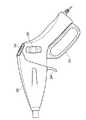
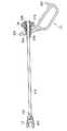
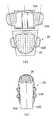
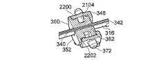
図1は、本発明の一例にしたがった電気手術器具1を示している。器具1は、近位側のハンドル部分10と、該近位側ハンドル部分から遠ざかる遠位方向に伸びる外側シャフト12と、該外側シャフトの遠位端に取り付けられた遠位端エフェクタアセンブリ14とを含む。エンドエフェクタアセンブリ14は、例えば、開閉するように配置された対向する1組の挟持部であってよく、対向する挟持部の内表面上に又は内表面として配置された1つ以上の電極を含み、これらの電極は、使用時に、組織の封止又は凝固のための電気手術高周波(RF)信号を受信するための接続部を有する。挟持部は、更に、ユーザによって作動されたときに機械的な切断刃などが突出しえるスロット又はその他の開口部を、対向する内表面内に提供される。使用時には、ハンドル10は、ユーザによって、挟持部14間に組織をクランプするために第1の方式で作動され、電極にRF電流を供給して組織を凝固させるために第2の方式で作動される。挟持部14は、器具1の能動構成要素が常に見えているようにするために湾曲されてよい。これは、使用時におけるユーザの装置視野を妨げる人体領域の手術に使用される血管封止装置において重要である。ハンドル10は、刃を挟持部14間に突出させそれによって間にクランプされた組織を切断させるために、ユーザによって、第3の方式で作動されてよい。必要とされる切断及び封止が完了したら、ユーザは、挟持部14から組織を解放させることができる。1. 1. Outline of Instrument Configuration FIG. 1 shows an
ハンドル10は、図2に示されるように、2枚のクラムシェル成形物300、302で形成されたケーシング20を含み、該ケーシングは、挟持部14を動作させる及び回転させるために、並びに組織を凝固させる及び切断するために必要とされる、全てのコンポーネントを収容する。組み立てられた装置の中のクラムシェル成形物は、内部のコンポーネントが内側に組み付けられたら、超音波によって溶接される。ハンドル10は、挟持部14間に組織をクランプするためのクランプハンドル22と、組織を切断するためのトリガ24と、組織を凝固させるために挟持部14の中の電極へのRF供給を作動させる及び停止させるためのスイッチ26と、異なる角度から組織に到達するために挟持部14を回転させるための回転ホイール28とを含む。しかるがゆえに、ハンドル10の構成は、器具1及びその全ての機能が片手を使用して操作できて、操作のための全ての機構が容易にアクセス可能であるような構成である。 The
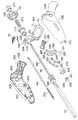
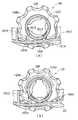
図3は、器具1がその機能を実施するために必要とされる器具1の全ての特徴を示しており、ケーシングのクラムシェル成形物300、302内に収容されたものを含む。挟持部14間に組織をクランプするために、クランプハンドル22を使用してクランプ機構が作動される。クランプハンドル22は、更に、カラー304を含み、該カラー304は、クランプハンドル22が回転するための支点として機能するヒンジ306を含む。例えば、ヒンジ306は、2本の外向きのピンであってよく、これらのピンは、クラムシェル成形物300、302と一体である対応する成形物308内に収まり、それによって、クラ
ンプハンドル22が回転するための固定点を提供する。クランプ機構は、更に、図4〜7によって更に示されるように、カラー成形物310と、バネ312と、内側成形物314とを含み、これらは全て、駆動シャフト316に沿って装着される。FIG. 3 shows all the features of the
カラー304は、カラー成形物310が中に着座するための鍵穴状の孔318を含む。孔318は、底部でよりも頂部での方が大きい直径を有し、カラー成形物310は、図8aによって示されるように、孔318の下部内に着座するように配置される。組み立ての際は、カラー成形物310は、図8b〜cによって示されるように、2つのフランジ800と802との間にカラー304が着座するように、孔318の、大きい方の部分に容易に通される。図8dによって示されるように、カラー304は、次いで、鍵穴状の孔318の、小さい方の部分をカラー成形物310に係合させるために、上向きに押される。ヒンジ306が、ケーシング20内でヒンジ成形物308に接続されると、カラー成形物310は、孔318の下部内に保持され、孔318内で自由に回転運動することができる。 The
図6に示されるように、カラー成形物310、バネ312、及び内側成形物314は、突出部材600、602を超えて軸方向に移動することができないように、これらの突出部材600と602との間に保持される。これに関しては、駆動シャフト316の近位端にある突出部材602は、駆動シャフト316が内側成形物314の近位端における通路604に通されることを可能にできるように、圧縮可能である。駆動シャフト316は、開口606に到達するまで通路604内で推し進められ、そこで、突出部材602は、駆動シャフト316の壁と同一面上にくるように圧縮状態から解放される。それどころか、突出部材602は、突出部材602の渡りが通路604の直径を超えるように扇形に広がって連結、開口606の壁に押し付けられる。その結果、駆動シャフト316は、通路604内で逆戻りすることができず、そうして適所に固定される。 As shown in FIG. 6, the
突出部材600と602との間の距離は、カラー成形物310と内側成形物314との間でバネ312が少なくとも部分的に圧縮されるような距離である。この事前圧縮は、更に詳しく後述されるように、クランプ機構が作動されるときに適切なクランプ荷重がかかることを保証するために重要である。カラー成形物310及び内側成形物314は、ともに、バネ312が伸びて入り込むための空洞608、610を含む。具体的には、カラー成形物310の長さのうちのかなりの割合が、バネ312を収容している。この配置は、バネ312が使用時にその密着長さに達することがないことを保証するために重要である長めのバネ312を可能にする。 The distance between the projecting
駆動シャフト316の本体は、外側シャフト12内にあり、駆動シャフト316の遠位端は、外側シャフト12の遠位端及び挟持部14の両方に連結されている。駆動シャフト316は、外側シャフト12内で軸方向に移動し、図4及び図5aからわかるように、挟持部14を開位置から閉位置へ動かすのは、この軸方向移動である。例えば、駆動シャフト316は、カムスロット402の中の駆動ピン400によって挟持部14に結合され、これによって、カムスロット402内における駆動ピン400の動きが、挟持部14を開位置と閉位置との間で動かす。駆動シャフト316と、外側シャフト12と、挟持部14との間の結合は、駆動シャフト316の回転運動が外側シャフト12及び挟持部14に伝達されるような結合である。 The body of the
外側シャフト12及び駆動シャフト316は、シャフト成形物320によって、更に別の地点で連結される。シャフト成形物320は、ケーシング20のソケット322内に着座し、それによって、外側シャフト12をケーシング20に連結する。外側シャフト12は、例えば、図9bに示されるように、シャフト成形物320内の対応する切り込み902と協働するスナップ式ブなどの任意の適切な手段によって、シャフト成形物320に取り付けられる。駆動シャフト316は、図10aに示されるように、駆動シャフト316
の断面「T」字形状に一致する孔(不図示)を通ってシャフト成形物320のボディに通される。シャフト成形物320は、ソケット322内で自由に回転可能であるように配置される。例えば、シャフト成形物320は、クラムシェル成形物300、302内に提供された同心状の合わせ面908、910内で回転する円筒状のフランジ特徴904、906を含んでいてよい。したがって、シャフト成形物320は、駆動シャフト316とともに回転し、これは更に、この回転運動を外側シャフト12及び挟持部4に伝達する。シャフト成形物320は、こうして駆動シャフト316のための回転・軸方向ガイドとして機能する。The
It is passed through the body of the shaft molded
クランプハンドル22は、ケーシング20の近位端328内に着座するラッチ成形物326と協働するように配置されたラッチ324を含む。ラッチ成形物326は、例えば、図3によって示されるように、クラムシェル成形物300、302のいずれかと一体である成形されたピン330によって、又は単純に、図11によって示されるように、クラムシェル成形物300と一体である成形された壁1100によってなど、任意の適切な手段によって適所に保持されてよい。挟持部14を閉じさせるために、クランプハンドル22がケーシング20に向かって動かされるときは、ラッチ324は、クランプハンドル22をこの位置に保持できるように、開口1102を通ってケーシング20に入り、ラッチ成形物326に係合する。図26a〜fに示されるように、ラッチ成形物326は、双方向バネ1104と、ラッチ324がそれに沿って横断するためのカム経路1106とを含む。図46に示されるように、ラッチ機構は、また、ラッチ324が行き止まったときにラッチ324をユーザが手動で解放することを可能にするためのオーバーライドコンポーネント4600と、ラッチ機構を完全に無効化するためのロックアウトコンポーネント4602とを含んでよい。オーバーライドコンポーネント4600及びロックアウトコンポーネント4602は、ラッチ成形物326上に提供されてよい、又はケーシングの内側と一体にされてよい。 The clamp handle 22 includes a
上述のように、ハンドル10は、更に、回転ホイール28を含み、該回転ホイール28は、内側成形物314を包み込むように配置される。これに関して、回転ホイール28及び内側成形物314は、図12によって示されるように、かみ合わせ部材1200、1202を有する。これらのかみ合わせ部材1200、1202は、図13a〜bからわかるように、回転ホイール28と内側成形物314とが、回転ホイール28内における内側成形物314の軸方向移動を可能にしつつも一緒に回転するように、結合される。したがって、回転ホイール28の回転は、内側成形物314の回転を引き起こし、該回転は、続いて駆動シャフト316及びカラー成形物310を回転させる。安定のために、回転ホイール28は、クラムシェル成形物300、302と一体である内側合わせ面(不図示)上で回転式に滑動する円筒状の面1204を含む。 As described above, the
ユーザによって挟持部14を回転可能にするために、ケーシング20は、回転ホイール28の波形部分336が突き出すための2つの開口332、334を有する。2つの開口332、334は、ハンドルの各側で互いに相対しており、台形状である。具体的には、台形状の孔は、ハンドルの長手方向軸に直交する平行の辺を有し、これらの平行辺は、一方の辺がもう一方の辺よりも長く、長い方の辺が孔の前方端に、短い方の辺が孔の後方端にある。波形部分336は、ユーザの親指又はそれ以外の指に快適になじむように、適宜に傾斜されている。これに関して、波形部分336は、図14a〜bに示されるように、回転面に対して一定の角度で切り取られている。具体的には、波形部分の傾斜部分の角度は、回転ホイール28の領域における外部ケーシングの角度に実質的に等しいことが望ましい。 The
回転ホイール28は、図5a〜bに示されるように、回転度を制限するための少なくとも1つのストップ部材1500も含む。ストップ部材1500は、ケーシング20と一体
であるストッパー1502、1504と相互に作用する。回転ホイール28が回転されるのに伴って、ストップ部材1500は、ストッパー1502、1504に阻まれ、それによって、更なる回転を阻止する。例えば、ストッパー1502、1504は、回転ホイールを270度の回転に制限してよい。同様に、シャフト成形物320も、図16a〜dによって示されるように、ケーシング20と一体であるストッパー1602、1604と相互に作用するストップ部材1600を含む。シャフト成形物320のストップ部材1600及びそのそれぞれのストッパー1602、1604は、回転が同程度に制限されるように、回転ホイール28のストップ部材1500及びそのそれぞれのストッパー1502、1504と半径方向に揃えられる。要するに、回転ホイール28が回転されるのに伴って、回転ホイール28上のストップ部材1500が阻まれる半径方向地点は、シャフト成形物320上のストップ部材1600が阻まれる半径方向地点と同じである。例えば、図15b及び図16aにおいて、挟持部14は、(図16bに示された)ニュートラルな向きから反時計回りに90度回転されている。この回転の自由は、ユーザが器具1全体を回転させる必要なく様々な角度から組織を把持できることを意味する。The
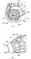
上述のように、何らかの適切な回路構成を通じて挟持部14の中の電極に送られるRF信号を活性化及び非活性化するために、例えば小型プリント回路基板(PCB)338上の2つの侵入保護されたスイッチなどのスイッチボタン26が提供される。図17に示されるように、PCB338は、ジェネレータ(不図示)からのRF出力を受信するための接続コード1700に、並びにRF電流を挟持部14の中の電極に供給するための、1本は活性電極のための及びもう1本は戻り電極のための電気配線1702、1704に接続される。図17及び図18a〜bに示されるように、配線1702、1704は、ガイドスロット1800からシャフト成形物320の内部空洞1802に入って外側シャフト12内を進む前に、シャフト成形物320の下に及び周りに巻き付けられる。配線1702、1704をこのようにシャフト成形物320に巻き付けることによって、配線1702、1704は、駆動シャフト316の回転を可能にしつつも容易な組み立てを可能にできるように、コンパクトな構成に維持される。これに関して、配線1702、1704は、駆動シャフト316の回転とともに巻きを解かれる及び再び巻かれる。また、クラムシェル成形物の1つ300は、活性配線1702及び戻り配線1704を侵入保護スイッチ338の配線1908、1910に接続する配線コンタクト1904、1906を収容するための、2つの直列に配置された成形ポケット1900、1902を含む。対向するクラムシェル成形物302は、コンタクト1904、1906をポケット1900、1902内に保持するための、対応するリブ特徴(不図示)を含む。その結果、2つの配線コンタクト1904、1906は、各ポケット1900、1902を一方のコンタクトのみが通れるように長手方向に分離され、それによって、各コンタクト1904、1906と配線との間に物理的障壁が提供される。これは、外側シャフト12を経てケーシング20に入るかもしれないあらゆる流体からコンタクト1904、1906自体を保護しつつ、コンタクト1904、1906によって引き起こされる配線の絶縁損傷のリスクを阻止する。 As mentioned above, two intrusion protections, for example, on a small printed circuit board (PCB) 338, to activate and deactivate the RF signal sent to the electrodes in the
切断機構を見ると、挟持部14間にクランプされた組織を切断するための刃340が、駆動シャフト316の長さに沿って走る中心走路342内に提供される。走路342に沿って且つ挟持部14間で刃340を作動させるための機構は、トリガ24を通じて操作される。トリガ24は、トリガ成形物344と、刃駆動成形物346と、刃カラー成形物348と、引っ張りバネ350と、刃成形物352とで形成された駆動アセンブリを作動させる。駆動アセンブリは、クランプ機構の、シャフト成形物320とハンドルカラー304との間に配置される。図20a〜bに示されるように、駆動アセンブリは、オフセットスライダ−クランク機構として機能し、それによって、ユーザによってトリガ24に及ぼされる力が駆動シャフト316に沿った刃成形物352の軸方向移動に変換され、該移動が更に、取り付けられた刃340を駆動する。 Looking at the cutting mechanism, a
図21、図22、及び図23に示されるように、刃成形物352は、刃カラー成形物348内に着座するように配置される。図22に示されるように、刃カラー成形物348は、刃成形物352の周囲の溝2202とかみ合うリップ2200を含む。図23に示されるように、刃成形物352は、駆動シャフト316及び刃340を受け入れるための「T」字形状の孔2300を有する。刃成形物352は、更に、刃340の近位端のための、図21に示されるような内部切り抜き2100を含み、刃の端2102は、図24a〜cで実演されるような容易な組み立てを可能にできるように、刃成形物352の内部切り抜き2100に一致する形状にされる。刃成形物352は、刃カラー成形物348から、これらの2つの成形物が同心状に回転できるように回転式に隔離される。その結果、刃成形物352は、駆動シャフト316とともに回転することができる。 As shown in FIGS. 21, 22, and 23, the blade molded
上述のように、挟持部14は、湾曲されてよい。刃340が、十分な切断能力を尚も維持しつつもこの湾曲に沿って推し進められることを可能にするためには、湾曲した走路を通る切断刃340の摩擦力が、最小限に抑えられなければならない。摩擦力は、走路342内における刃340の摩擦係数と、刃340が走路342の壁に及ぼす曲げに起因する力との積である。この摩擦力は、例えば、刃の側面に低摩擦コーティングを追加することによって、及び/又は刃が切断力の方向には剛性を維持しつつ走路342に沿って曲がることができるように刃340を選択的に弱体化させて刃の遠位端の柔軟性を徐々に変化させることによって、低減されてよい。選択的弱体化は、例えば、図3及び図47a〜cに示されるように、遠位端に1つ以上の孔354を提供することによって、又は図47dに示されるように、刃340の厚さを徐々に変化させることによって、提供されてよい。或いは、図47eによって示されるように、刃の長さにわたる曲げ剛性を制御するために、遠位端におけるパターン形成されたレーザ切断部分4712又は化学エッチング部分が使用されてよく、このような切断部分間の間隔は、遠位端から近位端にかけて一定であってよい又は徐々に増してよい。 As described above, the sandwiching
使用時には、血液及び組織が、器具1の遠位端内に蓄積することがある。具体的には、血液及び組織が、刃340を駆動シャフト316内で詰まらせることがある。したがって、駆動シャフト316の遠位端は、図10b〜cに示されるように、血液及び組織が蓄積して詰まる駆動シャフト316の表面積を減少させるための切り抜き部分1000、1002を含んでいてよい。例えば、切り抜き部分は、遠位端が、支えとなる基部を伴わずに2枚の側壁を有するような、又は遠位端が、支えとなる基部と分岐した側壁とを含むようなものであってよい。 During use, blood and tissue may accumulate in the distal end of
2. 器具の動作
装置の全体的な構成が説明されたところで、次は、使用時における電気手術器具1の全体的な動作が論じられる。その後、装置の特定の態様の構成及び動作に関して更に詳細な説明がなされる。2. Instrument Operation Now that the overall configuration of the device has been described, the overall operation of the
上述のように、電気手術器具のハンドル10は、i)挟持部14の間に組織をクランプするように、ii)(もしユーザが望むならば、)挟持部を適所にラッチするように、iii)挟持部14の間にクランプされた組織を凝固させるために、挟持部14の中の電極にRF信号を送るように、及びiv)挟持部14の間にクランプされた組織を切断するために、挟持部14間に刃340を繰り出させるように、配置される。ハンドル10は、また、ユーザがハンドル10全体を回転させる必要なく様々な角度で組織をクランプすることを可能にできるように、挟持部14を回転させることもできる。その結果が、挟持部間の組織を、同じ電気手術器具によって切断される前に又は同じ電気手術器具によって切断されるのと同時に封止できることである。更に、これらの効果は、器具を外科医が片手で操作することで達成できる。 As mentioned above, the
2.1 クランプ機構
挟持部14間に組織をクランプするために、ユーザは、クランプハンドル22を、ラッチ324がケーシング20内のラッチ成形物326に係合するまでケーシング20の近位端328に向かって握り込む。この動きは、図8e〜fによって示されるように、駆動ハンドル22をそのヒンジ306を中心に枢動させ、図4及び図5aによって示されるように、カラー304の端をフランジ800に対して押し付けて、カラー成形物310、バネ、及び内側成形物314を駆動シャフト316に沿って近位方向に推し進める。上述のように、内側成形物314は、突出部材602を通じて駆動シャフト316に取り付けられる。したがって、内側成形物314が軸方向に押し戻されるのに伴って、駆動シャフト316も軸方向に移動され、これは、挟持部14のカムスロット402の中のピン400を駆動し、それによって、挟持部14を閉じさせる。しかるがゆえに、駆動ハンドル22からの荷重は、カラー成形物310、バネ312、及び内側成形物314のバネ機構を通じて駆動シャフト316に伝達される。2.1 Clamping Mechanism To clamp the tissue between the
図5bによって示されるように、組織が挟持部14間にクランプされると、バネ312は、組織にかかる力を制限する働きをする。カラー成形物310、バネ312、及び内側成形物314が軸方向への移動を停止した後、カラー304がフランジ800を押し続けると、バネ312にかかる圧縮力は、最終的に、バネ312がカラー成形物310と内側成形物314との間で圧縮し始める圧縮力閾値に到達する。バネ312が更に圧縮するのに伴って、駆動ハンドル22は、クランプされた組織に更なる力を及ぼすことなくラッチ位置まで駆動できる。要するに、駆動ハンドル22の荷重は、これ以上駆動シャフト316に伝達されることはなく、バネ312によって効果的に吸収される。しかるがゆえに、バネ312は、適切な大きさの荷重が挟持部14に伝達されることを保証する。バネ312がないと、駆動ハンドル22の作動は、駆動シャフト316に及びそれに続いて挟持部14及び組織に伝達される荷重を増加させ続ける。これは、ユーザが駆動ハンドル22をラッチ324に係合させるために握り込むにつれて、組織の機械的損傷を招く恐れがある。 As shown by FIG. 5b, when the tissue is clamped between the
上述のように、カラー成形物310及び内側成形物314の中の空洞608、610は、より大きなバネ312を可能にするために、協働して機能する。これは、より長いバネ運動距離を可能にし、バネ312が使用時にその密着長さまで完全に圧縮されることがないようにする。もし、バネ312がその密着長さに達したとすると、バネは、駆動ハンドル22によって及ぼされる荷重をこれ以上吸収しなくなり、力は、挟持部14に再び伝達されることになる。 As mentioned above, the
2.2 ラッチ機構
挟持部14間に組織がクランプされると、挟持部14は、図26a〜fによって示されるように、駆動ハンドル上のラッチ324をケーシング20の内部のラッチ成形物326に係合させることによって閉位置にロックできる。ラッチ324は、開口1102を通ってケーシング20に入るのに伴って、ラッチ成形物326に係合し、該成形物326をケーシング20内で押し下げ、それによってバネ1104を伸長させる。図26b〜cに示されるように、ラッチ324は、カム経路1106の側面上を、その最大位置に到達するまで駆け上る。この地点で、駆動ハンドル22は、これ以上圧縮できず、バネ1104は、図26dに示されるように、ラッチ324がカム経路1106の「V」字型ポケットに嵌り込んで駆動ハンドル22を圧縮位置に及び挟持部14を閉位置に保持するように、ラッチ成形物326をケーシング20の内部へ引き戻す。2.2 Latch mechanism When the tissue is clamped between the
このラッチ位置では、ユーザの手は、以下で論じられるように、器具1の他の機能を自由に操作することができる。 In this latch position, the user's hand is free to operate other functions of
ラッチ324をケーシング20から解放して挟持部14を開かせるためには、ユーザは、図26eによって示されるように、駆動ハンドル22をケーシング20に向かって握り込んで、ラッチ324をカム経路1106のポケットから解放しなければならない。バネ1104の力は、ラッチ324が、図26e〜fによって示されるように、カム経路1106の側面上で反対方向に進んで開口1102から出るように、ラッチ成形物326をケーシング20内で更に引っ張り上げる。ラッチ成形物326は、次いで、ケーシング20内でその元の位置に戻る。 To release the
2.3 切断機構
挟持部が閉位置にある間、ユーザは、間にクランプされた組織を切断する必要があるかもしれない。組織を切断するために、駆動アセンブリの作動によって、挟持部14間で刃340が駆動される。2.3 Cutting Mechanism While the clamp is in the closed position, the user may need to cut the tissue clamped in between. To cut the tissue, the actuation of the drive assembly drives the
駆動アセンブリは、スライダ−クランク機構として機能する3枢着配置である。図25b〜cによって示されるように、ユーザがトリガ24をケーシング20に向かって後方へ引くのに伴って、例えば、図3に示されたクラムシェル成形物300、302と一体である対応する成形物356に接続する外向きのピン358によって、ケーシング20に固定された枢着点Aを中心として、トリガ24がトリガ成形物344をてこ作用で動かす。これは、トリガ成形物344と駆動成形物346とを接続している枢着点Bをその中心位置へ促し、それによって、刃カラー348、刃成形物352、及び刃340を、クランプされた組織を刃340が切断することができる十分に強い力で駆動シャフト316に沿って駆動する。これに関連して、トリガ24にかかる荷重が、トリガ成形物344及び駆動成形物346を通じて刃カラー348及び刃成形物352に伝達される。枢着点Bが中心を超えてその伸展位置へ動くにつれて、刃カラー348及び刃成形物352が駆動シャフト316に沿って駆動される速度が加速し、そうして刃340の力を増加させる。しかるがゆえに、ユーザが追加の力をトリガ24に及ぼすことなしに、刃340が組織に切り込む力が増大する。 The drive assembly is a triaxial arrangement that acts as a slider-crank mechanism. Corresponding moldings that are integral with, for example, the
シャフト成形物320は、刃カラー348及び刃成形物352のためのストップ地点として機能する。したがって、枢着点Bは、駆動シャフト316に対して常に他の2つの枢着点A、Cよりも上方にとどまる。 The
トリガ24の作動時において、トリガ24に及ぼされる力は、引っ張りバネ350が駆動シャフト316と同じ面に沿って伸長して刃カラー348及び刃成形物352の軸方向移動を可能にするように引っ張りバネ350の圧縮力に打ち勝つのに十分な大きさである。トリガ24の解放時には、引っ張りバネ350は、再び圧縮して駆動アセンブリをその元の位置に撤退させる。これに関して、引っ張りバネ350の張力は、ユーザによる介入を必要とすることなく刃340を厚い組織を経て撤退させるのに十分な強さである。 When the
2.4 シャフト回転
使用時に、ユーザは、器具1全体を動かす必要なく様々な角度から組織に到達する必要があるかもしれない。したがって、挟持部14は、回転ホイール28によってハンドル10に相対的に回転可能であることが有利である。これは、挟持部14が図16a〜dに示されるような湾曲した走路上にある場合に特に有益である。上述のように、回転ホイール28は、内側成形物314が回転ホイール28とともに回転するように、かみ合い部材1200、1202を通じて内側成形物314に連結される。駆動シャフト316の端が内側成形物314に接続されているので、駆動シャフト316も回転し、この回転は引き続き、反対側の端にある挟持部14を回転させる。2.4 Shaft Rotation When used, the user may need to reach the tissue from various angles without having to move the
クランプ機構の動作を妨げることなくこの回転運動を促すために、カラー成形物310
は、カラー成形物310も駆動シャフト316とともに回転するように、ハンドルカラー304内で回転式に隔離される。同様に、切断機構の動作を妨げることなく駆動シャフト316回転を可能にできるように、刃成形物352は、刃カラー348内で回転式に隔離される。In order to promote this rotational movement without interfering with the operation of the clamp mechanism, the color molded
Is rotatably isolated within the
回転運動を外側シャフト12に伝達するために、シャフト成形物320は、そのソケット322内で回転式に隔離される。上述のように、シャフト成形物320は、器具1の全長に沿ったシャフト316に相対的な回転運動を制御できるように、回転ガイドとして機能する。また、活性配線1702及び戻り配線1704は、コンポーネントの回転の結果としてこれらの配線1702、1704に及ぼされる損傷を防ぐことができるように、ケーシング20内に配置される。上述のように、配線1702、1704は、駆動シャフト316の回転度を可能にできるように、シャフト成形物320の周りに巻き付けられる。その結果、配線1702、2704は、シャフト成形物320の回転に伴って巻きを解かれる及び再び巻かれる。 In order to transmit the rotational motion to the
2.5 電極活性化
挟持部14が閉位置にある間、ユーザは、間にクランプされた組織を凝固させること及び封止することを望むかもしれない。これを行うために、ユーザは、ケーシング20頂部のスイッチボタン26を使用して、電極の活性化を開始させる。スイッチボタン26は、ユーザが装置を片手で使用している間に容易にボタン26にアクセスできるように、適宜に配置されている。この際は、組織を凝固させる及び封止するために、適切なRF信号が挟持部14の中の電極に送られる。RF信号は、所望の効果に応じて純粋波形又は混合波形であってよい。2.5 While the
装置全体としての構成及び動作の概要が述べられたところで、次は、装置の特定の態様の構成及び動作に関して更に詳細な説明が行われる。 Now that the configuration and operation of the device as a whole has been outlined, a more detailed description of the configuration and operation of a particular aspect of the device will be given next.
3. クランプ機構アセンブリ及び動作
上述のように、電気手術器具1の近位ハンドル部分10は、遠位エンドエフェクタアセンブリ14の一態様をこのエンドエフェクタアセンブリ14が第1の状態と第2の状態との間で動くように作動させるための、第1の機構を含む。例えば、エンドエフェクタアセンブリ14は、開閉するように配置された対向する1組の挟持部14であってよい。これらの挟持部14の動きをトリガするために使用される機構は、駆動ハンドル22と、2つのたる型成形物310、314と、それらの間で圧縮されるバネ312とを含むいわゆるクランプ機構であり、駆動ハンドル22、成形物310、314、及びバネ312は、図4及び図5a〜bに示されるように、全て、挟持部14とハンドル10との間に伸びる細長い棒316に沿って装着される。3. 3. Clamp Mechanism Assembly and Operation As described above, the
図8aに示されるように、駆動ハンドル22は、カラー成形物310が中に着座するカラー304を含む。カラー304は、鍵穴又は8の字のような形状にされた孔318を含む。このように、孔318は、2つの連続した孔804、806で形成され、頂部の孔804は、底部の孔806よりも大きい渡り直径を有する。 As shown in FIG. 8a, the
カラー成形物310は、長手方向に相隔てられた2つのフランジ部分800、802を有する円筒状の又はたる型のコンポーネントである。近位側フランジ800の直径は、上部の孔804及び下部の孔806のいずれよりも大きい。遠位側フランジ802の直径は、上部の孔804よりも小さく且つ下部の孔806よりも大きい。 The
組み立て時には、先ず、図8b〜cによって示されるように、カラー成形物310が上部の孔804に挿入される。遠位側フランジ802は、上部の孔804よりも小さいので
容易に通り抜け、これに対し、近位側フランジ800は、カラー成形物310が上部の孔804を完全に通り抜けるのを防ぐのに十分な大きさであってよい。図8dによって示されるように、カラー8304は、次いで、下部の孔806をカラー成形物310に係合させるために押し上げられる。At the time of assembly, first, the
組み立てられたら、カラー成形物310は、カラー304の下部の孔806内にとどまり、図8eに示されるように、その2つのフランジ800、802がカラー304の両側にくるように位置決めされる。下部の孔806は、両フランジ800、802よりも小さい直径を有するので、カラー成形物310は、下部の孔806を通るようにカラー成形物310を単純に押すことによって取り除くことはできない。反対に、2つのフランジ800と802との間のカラー成形物310のボディは、下部の孔806よりも僅かに小さい直径を有する。したがって、カラー成形物310は、回転運動を可能にするのに十分な緩さで下部の孔806内に着座する。 Once assembled, the
図8eからわかるように、2つのフランジ800と802との間の長手方向における距離は、カラー304がフランジ800と802との間にぴたりと着座するように、カラー304の厚さよりも僅かに大きいだけである。これは、駆動ハンドル22の動きがカラー成形物310に直接伝達され、それに続いてクランプ機構のその他のコンポーネントに伝達されることを保証する。これは、挟持部14が駆動ハンドル22の動きに反応すること、及び駆動ハンドル22の作動と挟持部14の動きとの間に遅延反応がないことを保証するために、特に重要である。 As can be seen from FIG. 8e, the longitudinal distance between the two
カラー成形物310及び駆動ハンドル22が組み立てられたら、残りのコンポーネントも組み付けることができる。 Once the
駆動シャフト316は、図6に示されるように、その近位端に1つ以上の突出部材602が位置付けられた細長い棒である。突出部材602は、駆動シャフト316の表面から扇形に開く柔軟性のタブである。要するに、突出部材602は、駆動シャフト316の表面と同一面上にくるように押されえるように変形可能であり、ただし、抵抗力の解放時にはその元の位置に戻る。これは、駆動シャフト316が、次に説明されるように、組み立て時にクランプ機構の全てのコンポーネントに容易に通されることを可能にする。 The
カラー成形物310は、2つの部分に分割された内部空洞を有する。第1の部分は、駆動シャフト316を受け入れるための狭い通路、即ちスロット607であり、カラー成形物310の遠位端は、図3に示されるように、駆動シャフト316の断面「T」字形状に一致する開口311を含む。通路607の直径は、安定のための滑合を提供できるように、駆動シャフト316の直径よりも僅かに広いだけである。駆動シャフト316の挿入時に、突出部材602は、駆動シャフトが最後まで押し通されることを可能にするために、平らに押しつぶされる。 The
第2の部分は、バネ312の一端を収容するのに十分な大きさのチャンバ608である。チャンバ608は、カラー成形物310の長さのうちの任意の適切な割合に及ぶことができる。例えば、チャンバ608の長さは、カラー成形物310の長さの25%程度であってよい、又はカラー成形物310の長さの75%に及んでよい。 The second part is a
チャンバ608は、駆動シャフト316がカラー成形物310に通されるのに伴って突出部材602がチャンバ608に到達したときに、突出部材602が広がってその元の構成に戻るように、カラー成形物通路607よりも大幅に大きい。 The
カラー成形物310と駆動ハンドル22とからなるアセンブリは、カラー成形物310
が第2の組の突出部材600に到達するまで駆動シャフト316に沿って押し進められる。これらの突出部材600は、カラー成形物310が駆動シャフト316に沿ってこれ以上先に進むことを防ぐための妨害を提供するために、カラー成形物310上の開口311よりも広い渡りを有する。しかるがゆえに、突出部材600は、何らかの力が突出部材600に加わることによって又は突出部材600が内向きに押されることによってカラー成形物310が突出部材600から抜け出ることがないように、十分に剛性でなければならない。The assembly including the color molded
Is pushed along the
駆動シャフト316は、次いで、バネ312の中心に通される。好ましくは、バネ312は、バネ312と駆動シャフト316との間に締まり嵌めを提供するために、駆動シャフト316よりも僅かに大きいだけの直径を有する。バネ312は、次いで、バネ312の端がカラー成形物チャンバ608を満たすまで、駆動シャフト316に沿って押し進められる。 The
内側成形物314は、2つの区域に分割された内部空洞を有する円筒状の又はたる型のコンポーネントである。第1の区域は、バネ312がカラー成形物310及び内側成形物314によって部分的に包み込まれるようにバネ312の一端が収容されるチャンバ610である。第2の区域は、駆動シャフト316を受け入れるための狭い通路、即ちスロット603である。通路603は、2つの部分604、606に分割される。通路の第1の部分604は、駆動シャフト316が通されることを可能にできるような形状にされ、シャフトが通される際に、柔軟性のタブ602は、平らに押しつぶされる。しかるがゆえに、第1の通路部分604の直径は、滑合を提供できるように、駆動シャフト316の直径よりも僅かに広いだけである。カラー成形物通路607内及び内側成形物通路603内の両方における駆動シャフト316の滑合は、駆動シャフト316が適所にしっかりと保持されることを意味する。これは、ケーシング20内における駆動シャフト316の安定性を向上させ、これは、エンドエフェクタ14の最大限の制御を保証するために特に重要である。
第2の通路部分606は、その中へ突出部材602が伸長できる肩部605を提供する。したがって、駆動シャフト316が通路604を通り、第2の通路部分606に入るのに伴って、平らにされた突出部材602は、扇形に開いてその元の非圧縮位置に戻る。突出部材602がひとたび第2の通路部分606の肩部605に係合すると、駆動シャフト316は、第1の通路部分604内を引き戻すことはできず、その結果、内側成形物314内に保持される。しかるがゆえに、第2の通路部分606の直径は、突出部材602が第1の通路部分604の直径を超えて広がることができる十分な広さでなければならない。このスナップ式接続を達成するためには、駆動シャフト316の一方の側でのみ、突出部材602が必要とされる。 The
このスナップ式接続は、内側成形物314のあらゆる軸方向移動が駆動シャフト316に伝達されるような接続である。同様に、例えば内側成形物314の周りに形成された回転ホイール28による内側成形物314のあらゆる回転運動も、駆動シャフト316に伝達される。 This snap connection is such that any axial movement of the
したがって、クランプ機構の組み立てを完了させるために、駆動シャフト316は、突出部材602が第2の通路部分606にスナップ式に嵌るまで、単純に、カラー成形物310、バネ312、及び最後に内側成形物314に通される。 Therefore, in order to complete the assembly of the clamp mechanism, the
駆動シャフト316に沿って組み付けられると、カラー成形物310、バネ312、及び内側成形物314は、バネ312がカラー成形物310及び内側成形物314によって部分的に包み込まれるように配置される。バネ312のかなりの割合の部分を収容するこ
とができるカラー成形物のチャンバ608及び内側成形物314のチャンバ610を提供することによって、ハンドル10内の更なる空間を使い果たすことなく更に長いバネ312を使用することが可能になる。しかるがゆえに、カラー成形物のチャンバ608及び内側成形物のチャンバ610が大きいほど、バネ312が長くなる。更に、突出部材600と602との間の距離は、バネ312がその装着時に初期の事前圧縮を受けるように、バネ312の両端がカラー成形物のチャンバ608及び内側成形物のチャンバ610の端壁612、614によってそれぞれ圧縮されることを意味する。これは、クランプ機構を作動させるためにハンドル22が動かされるときに適切な荷重が挟持部14にかかることを保証するために重要である。When assembled along the
また、内側成形物314は、図13a〜bに示される回転ホイール28などの、更なるたる型成形物内に内包されてよい。ここでは、内側成形物314は、回転ホイール28とともに回転するが、内部空洞1300内で、図13aに示されるような第1の位置と図13bに示されるような第2の位置との間で自由に軸方向に移動することができる。したがって、ホイール28の回転が、内側成形物314を回転させ、更には駆動シャフト316及び挟持部14を回転させる。 Further, the inner molded
全てのコンポーネントが組み立てられたら、駆動ハンドル22が、ケーシング20の内側に装着できる。これに関しては、駆動ハンドル22は、そのヒンジ306でケーシング20に接続される。例えば、ヒンジ306は、クラムシェル成形物300、302と一体である対応するヒンジ成形物308と合わさる2本の外向きのピンであってよい。これは、駆動ハンドル22が中心にして回転することができる支点を提供する。 Once all the components have been assembled, the
したがって、上記の配置は、追加のコンポーネントを必要とすることなく容易に且つ安全に組み立て可能である、エンドエフェクタアセンブリ14を作動させるための機構を提供する。 Therefore, the above arrangement provides a mechanism for operating the
使用時に、ユーザは、駆動ハンドル22をケーシング20の近位端328に向けて握り込み、それによって、駆動ハンドル22をそのヒンジ306を中心として回転させる。その際に、カラー304は、近位側フランジ800に押し付けられ、そうしてカラー成形物310を長手方向に移動させる。この長手方向移動は、図5aによって示されるように、バネ312、内側成形物314、及び駆動シャフト316をハンドル部分10の近位端に向かって戻らせる。駆動シャフト316は、例えばピン400及びカムスロット402からなる配置によって挟持部14に連結されるので、挟持部14は、開位置から閉位置へ動かされる。しかるがゆえに、駆動ハンドル22からの荷重は、カラー成形物310、バネ312、及び内側成形物314からなるバネ機構を通じて駆動シャフト316に伝達される。このバネ機構は、挟持部14間にクランプされた組織に及ぼされる力を制限する働きをするゆえに、特に重要である。 In use, the user grips the
駆動ハンドル22が握り込まれるのに伴って、カラー成形物310、バネ312、及び内側成形物314は、図5aに示されるように、挟持部14が完全に閉じられるように内側成形物314がその最も遠い近位位置に到達するまで、又は図5bによって示されるように、挟持部14がその間にクランプされた組織500ゆえにこれ以上閉じることができなくなるまで、軸方向に移動し続ける。後者の場合、駆動ハンドル22は、完全には作動されておらず、ラッチ324によってその場所に保持されている。引き続き、ユーザが駆動ハンドル22を握り込み、カラー304がフランジ800に押し付けられるのに伴って、バネ312にかかる圧縮力は、最終的に、図5bからわかるようにバネ312がカラー成形物310と内側成形物314との間で圧縮し始める圧縮力閾値に到達する。 As the
バネ312が更に圧縮するのに伴って、駆動ハンドル22は、クランプされた組織50
0に更なる力を及ぼすことなくラッチ位置まで駆動できる。要するに、駆動ハンドル22の荷重は、これ以上駆動シャフト316に伝達されることはなく、バネ312によって効果的に吸収される。しかるがゆえに、バネ312は、適切な大きさの荷重が挟持部14に伝達されることを保証する。バネ312がないと、駆動ハンドル22の作動は、駆動シャフト316に及びそれに続いて挟持部14及び組織500に伝達される荷重を増加させ続ける。これは、ユーザが駆動ハンドル22をラッチ324に係合させるために握り込むにつれて、組織500の機械的損傷を招く恐れがある。As the
It can be driven to the latch position without exerting any further force on 0. In short, the load of the
したがって、バネ312の事前圧縮は、内側成形物314がその軸方向における限界に到達したら直ちにバネ312がハンドル22の荷重を負うことを保証するために、重要である。同様に、より長いバネ312は、そのバネ312が使用時にその密着長さまで完全に圧縮されることがないように、より長いバネ運動距離を可能にする。もし、バネ312がその密着長さに達したとすると、バネ312は、駆動ハンドル22によって及ぼされる荷重をこれ以上吸収しなくなり、力は、挟持部14に再び伝達されることになる。 Therefore, pre-compression of the
挟持部14を閉位置に保持するためには、駆動ハンドル22上のラッチ324は、図26a〜fに示されるように、ケーシング20の近位端328の内側のラッチ成形物326に係合されなければならない。 To hold the
図11に示されるように、ラッチ成形物326は、ボディ部分1108と、バネ要素1104と、カム経路1106とを含む単一の一体成形コンポーネントである。ケーシング20の近位端328は、ボディ部分1108が中に着座する通路1110を画定する平行な壁1100を有する。通路1110の幅は、後述されるように、ボディ部分1108が通路1110内に保持されるが使用時には通路110内で上下に滑動することができるような幅である。これに関して、ラッチ成形物326は、ボディ部分1108が通路1110内で粘着することなく容易に滑動することを可能にするために、例えばポリテトラフルオロエチレン(PTFE)などの低摩擦材料で作成されることが好ましい。通路1112内における更なる安定性のために、ケーシング20内に成形ピン330が提供されてよく、該ピンは、図46に示されるように、ボディ部分1108上に提供されたカムスロット331に係合する。 As shown in FIG. 11, the
バネ1104は、ボディ部分1108の端に位置付けられ、ボディ部分1108を通路1110内でケーシング20の遠位端に向かって付勢するように配置される。バネ1104は、任意の構成であってよく、例えば、バネ1104は、図11に示されるような弓状又はループ状の形状であってよい。カム経路1106は、ボディ部分1108上に形成された成形された突出である。カム経路1106は、第1のカム表面1110と、切り込み1114と、第2のカム表面1116とを含み、「V」字型の成形物を形成している。 The
ラッチ324は、駆動ハンドル22の底部から伸びるアーム1118で形成される。アーム1118は、その端にピン1120を位置付けられ、該ピンは、カム経路1106を横断するのに適している。 The
使用時に、ラッチ324は、開口1102を通ってケーシング20に入る。ピン1120は、ボディ部分1108が通路1110内で引き下ろされ、それによってバネ1104が伸長されるように、ラッチ成形物326に係合する。図26b〜cに示されるように、ピン1120は、第1のカム表面1112の側面を、「V」の頂点に到達するまで駆け上る。この時点で、駆動ハンドル22は、これ以上圧縮できず、バネ1104は、ピン1110が切り込み1114に入り込むように、ボディ部分1108を通路1110内で引き戻し、そうして、図26dに示されるように、駆動ハンドル22を圧縮位置に及び挟持部14を閉位置に保持する。 In use, the
したがって、駆動ハンドル22をラッチするために、ユーザが行わなければならないことは、駆動ハンドルを完全圧縮位置まで作動させて、ピン1110が切り込み114に収まるのを待ち、次いで、駆動ハンドル22を解放するだけである。このラッチ位置では、ユーザの手は、トリガ24を使用して切断機構を作動させる、回転ホイール28を使用して挟持部14を回転させる、又はスイッチ26を使用して挟持部14の中の電極を作動させるなどの、器具1のその他の機能を自由に操作することができる。 Therefore, all the user has to do to latch the
ラッチ324をケーシング20から解放して挟持部14を開かせるためには、ユーザは、駆動ハンドル22をケーシング20に向けてもう一度握り込まなければならない。これは、図26eによって示されるように、ピン1120を切り込み1114から解放する。ピン1120が切り込み1114から出るのに伴って、伸長されたバネ1104の力は、図26e〜fによって示されるように、ピン1120が第2のカム表面1116の側面を駆け上るように、ボディ部分1108を通路1110内で引き戻す。ピン1120は、第2のカム表面1116の底部に到達するのに伴って、ボディ部分1108を更に通路1110内で押し上げ、したがって、ピン1120は、開口1102を通って出ていくことができる。ボディ部分1108は、すると、通路1110内でその元の位置に戻る。 In order to release the
したがって、駆動ハンドル22を解放するために、ユーザが行わなければならないことは、駆動ハンドル22をケーシング20の近位端に向けて握り込み、次いで、駆動ハンドル22をその元の開位置に戻れるようにするだけである。 Therefore, all that the user must do to release the
また、ラッチ成形物324は、図46に示されるようにボディ部分1108上に一体的に形成されたオーバーライドボタン4600を含んでよく、該オーバーライドボタン4600は、ピン1120が切り込み1114から自動的に外れて駆動ハンドル22を解放するように、カム経路1106の位置を変更するために係合される。したがって、もし、ラッチ機構が何らかの理由で機能しなくても、ユーザは、駆動ハンドル22を解放して挟持部14を開かせることができる。 Further, the latch molded
ユーザがラッチ機構を完全に解除することを可能にするために、ボディ部分1108には、ロックアウトバー4602も一体化されてよく、該ロックアウトバー4602は、ボディ部分1108を通路1110内で手動で滑動させるために、第1の位置と第2の位置との間で可動である。ロックアウトバー4602が第1の位置にあるときは、ボディ部分1108は、その正常位置にあり、したがって、ラッチ機構は、上述のように動作する。ユーザは、次いで、ロックアウトバー4602をその第2の位置へ動かしてよく、それによって、ボディ部分1108は、通路1110内で上方へ移動され、したがって、ピン1120は、第2のカム表面1116に沿って横断することしかできず、そうして切り込み1114への係合を阻止される。 A
ラッチ機構は、多くのエンドエフェクタアセンブリに適しているだろうことがわかる。例えば、このようなラッチは、切断刃340を作動位置に保持するために、切断機構のためのトリガ24上に提供されてよい。 It turns out that the latch mechanism would be suitable for many end effector assemblies. For example, such a latch may be provided on the
ラッチ324の解放時には、駆動ハンドル22をその元の位置に戻すことができる。その際に、カラー304は、近位側フランジ800にかかる荷重を解放して遠位側フランジ802を押し、それによって、カラー成形物310をその元の軸方向位置に引き戻す。その結果、バネ312、内側成形物314、及び駆動シャフト316も軸方向に引き戻され、これが更に、挟持部14を開構成に戻らせる。 When the
4. 切断機構アセンブリ及び動作
次に、切断機構の構造及び動作に関する様々な更なる特徴及び態様が説明される。上述のように、電気手術器具1の近位側のハンドル部分10は、遠位側のエンドエフェクタアセンブリ14の更なる態様を作動させるための第2の機構を含む。例えば、エンドエフェクタアセンブリ14は、1組の対向する挟持部14、及び刃340であってよく、刃340の遠位端は、挟持部14間にクランプされた組織を切断するために、上記挟持部14間で滑動するように配置される。駆動シャフト316の中心走路341内に配された刃340の動きをトリガするために使用される機構は、いわゆる切断機構である。切断機構は、駆動アーム2000と、刃駆動成形物346と、刃カラー成形物348と、刃成形物352と、引っ張りバネ350とを含み、これらは全て、結合されて、図20a〜b、図31、及び図32に示されるような3枢着スライダ−クランク機構を形成する。4. Cutting Mechanism Assembly and Operation Next, various additional features and aspects of the structure and operation of the cutting mechanism will be described. As mentioned above, the
駆動アーム2000は、トリガ24と、トリガ成形物344とで形成され、トリガ24は、切断機構を作動させるための指グリップ部材であり、トリガ成形物344は、「C」字型の側面輪郭と、駆動シャフト316が通される孔364とを有するカラーである。トリガ24とトリガ成形物344とが合流する地点は、駆動アーム2000が中心として回転される枢着点Aを提供する。この第1の枢着点Aは、例えば、クラムシェル成形物300、302と一体である対応する成形物356に接続する外向きのピン358によって、ケーシング20に固定される。 The
駆動アーム2000の遠位端、即ちトリガ成形物344の端は、刃駆動成形物346に枢動式に接続されて、第2の枢着点Bを形成する。刃駆動成形物346は、2本の平行アームと、それらの間の突っ張りとを有する「H」字型のフレームである。しかるがゆえに、刃駆動成形物346の平行アームは、例えば外向きのピン366と、合わせコネクタ368とによって、トリガ成形物344の一端に枢動式に接続される。反対側の端でも、刃駆動成形物346の平行アームは、例えば外向きのピン372と、合わせコネクタ370とによって、刃カラー成形物348に枢動式に接続されて、第3の枢着点Cを形成する。 The distal end of the
図21〜23に示されるように、刃カラー成形物348は、刃成形物352が中に着座するチャンバ2104を有する円筒状の又はたる型のコンポーネントであり、刃成形物352は、刃カラー成形物348のチャンバ2104の内側に収まるボディ362を有する円筒状の又はたる型のコンポーネントである。刃成形物352は、更に、チャンバ2104よりも大きい直径を有するフランジ360を含み、したがって、図22に示されるように、フランジ360は、刃カラー成形物348の遠位側のリップ2200に突き当たる。したがって、フランジ360は、刃成形物352の正しい端が刃カラー成形物348に作用することを保証する。 As shown in FIGS. 21-23, the
ボディ362は、刃成形物352と刃カラー成形物348とがスナップ式接続を通じて連結されるように、遠位側のリップ2200がかみ合う肩部を提供できるように、その周囲に小さい溝2202を提供される。遠位側のリップ2200は、刃成形物352がチャンバ2104内で自由に回転することを可能にしつつ、刃成形物352を刃カラー成形物348内で保持するために、溝2202と合わさる。しかるがゆえに、刃成形物352及び刃カラー成形物348は、同心状に自由に回転することができる。 The
刃カラー成形物348及び刃成形物352が組み立てられたら、図24a〜cによって示されるように、刃340を接続することができる。これに関して、刃成形物352は、図23によって示されるように、刃340及び駆動シャフト316の両方を受け入れられるような形状にされた「T」字型の孔2300を、その全長にわたって含む。 Once the
刃340の近位端は、刃340の残りの部分の全体輪郭を超えて伸びるタブ特徴2102を含む。要するに、刃340の近位端は、刃340の残りの部分と同じ軸方向面内には
ない。図24cに示されるように、ボディ362は、更に、タブ2100が中に保持される凹所2100を含む。組み立てを可能にするために、刃340の近位端は、斜切された縁2400を提供するために、タブ2102に対向する第1の地点で切り取られ、陥凹部分2402を提供するために、タブ2102に隣接する第2の地点で切り取られる。しかるがゆえに、刃340の近位端は、「L」字型の輪郭を有する。The proximal end of the
刃成形物352内に及び刃カラー成形物348内に刃340を組み付けるために、刃340は、図24a〜bに示されるように、タブ2102及び斜切された縁2400が刃成形物352の内部空洞2404に挿入されることが可能であるように、器具1の長手方向軸に対して一定の角度で「T」字型の孔2300に臨まされる。刃340は、次いで、図24cによって示されるように、タブ2102を凹所2100に押し込むことができるように、長手方向軸と同一直線上になるように引き下げられる。しかるがゆえに、タブ2102は、刃成形物352の肩部2406に効果的に引っ掛けられ、それによって、刃340の近位端を内部空洞2404内に保持する。 In order to assemble the
次いで、駆動シャフト316が、「T」字型孔2300に通されてよく、刃340は、図22及び図23に示されるように、中心走路342に受け入れられる。しかるがゆえに、刃カラー成形物348と刃成形物352とからなるアセンブリの、駆動シャフト316に沿った長手方向移動は、刃340を走路342に沿って動かす。 The
刃トリガアセンブリを完成させるために、例えばフック2002、2004によって、刃カラー成形物348と駆動アーム2000との間に引っ張りバネ350が伸びる。 To complete the blade trigger assembly, for example hooks 2002, 2004 extend a
使用時に、ユーザは、図25b〜cによって示されるように、駆動アーム2000を第1の枢着点Aを中心として枢動させるために、トリガ24をケーシング20に向けて引き戻す。その際に、第2の枢着点Bは、遠位方向に前方へ押され、これは、駆動成形物346に、刃カラー成形物348と刃成形物352とからなるアセンブリを駆動シャフトに沿って押させる。トリガ24にかかる荷重は、したがって、トリガ成形物344及び駆動成形物346を通じて刃カラー成形物348及び刃成形物352に伝達される。刃340の近位端は、上述のように、刃成形物352の内部に保持されるので、刃340は、刃カラー成形物348と刃成形352とからなるアセンブリとともに、中心走路342に沿って滑動する。刃成形物352は、刃カラー成形物348から回転式に隔離されるので、駆動シャフト316もまた、切断機構の動作を妨害することなく回転させられる。 During use, the user pulls the
機構の機能性は、ユーザの指が伸びていてあまり強くないときである刃340の移動開始時に、また、バネ350の力、走路342内の摩擦、及び厚い組織を貫くために必要とされる力などの多くの力が刃340の移動に対抗して作用している刃340の移動終了時に、優れた機械的利点を提供することができるように、最適化される。図27からわかるように、トリガ24には、ユーザによって一定の力が加えられる。機構は、このトリガ力を初期の高い刃340力に変換し、この力は、刃340が走路342に沿って動かされるのに伴って減少し、刃340が挟持部14に到達するのに伴って再び増加する。したがって、図28a〜bによって示されるように、枢着点Bがその後退位置から、β>90度になるようにその伸展位置へ動くのに伴って、刃カラー348及び刃成形物352が駆動シャフト316に沿って動かされる速度が加速し、その結果、刃340の力が増加する。しかるがゆえに、機構は、ユーザが追加の力をトリガ24に加える必要なく、挟持部14間にクランプされた組織を効果的に切断するのに十分な力で刃340を動かされることができる。 The functionality of the mechanism is required at the start of movement of the
加えて、切断機構は、湾曲した挟持部14に沿って刃340を推し進める必要があるかもしれず、これは、刃340の移動に対抗して作用する摩擦力を増加させる。摩擦力は、
走路342内における刃340の摩擦係数と、刃340が走路342の壁に及ぼす曲げに起因する力との積である。In addition, the cutting mechanism may need to push the
It is the product of the coefficient of friction of the
この摩擦力を低減させるために、刃の遠位端の、横方向における柔軟性が徐々に変化させられてよい。このような徐々に変化する柔軟性は、例えば、刃が切断力の方向における剛性を維持しつつも走路342に沿って曲がることができるように、刃340を選択的に弱体化させることによって実現されてよい。選択的弱体化は、例えば、図47aに示されるように、遠位端に1つ以上の孔又はスロット354を提供することによって提供されてよい。このような孔は、必要とされる柔軟性の程度に応じて、大きさ又は形状が一定又は可変であってよい。例えば、図47bでは、大きさが異なる2つの連続した孔4702、4704が提供され、大きい方の孔4702は、小さい方の孔4704よりも大きい柔軟性を提供する。別の例として、図47cでは、サイズ及び形状が異なる3つの孔4706、4708、4710が提供され、最も大きい孔4706は、更なる柔軟性を最も遠位の領域に提供できるように、最も遠位にある。選択的弱体化は、図47dに示されるように、刃340の遠位端が斜切された端4700であるように、刃340の厚さを徐々に変化させることによって実現されてもよい。 In order to reduce this frictional force, the lateral flexibility of the distal end of the blade may be gradually varied. Such gradually changing flexibility is achieved, for example, by selectively weakening the
或いは、図47eに示されるように、刃の長さにわたる曲げ剛性を制御するために、遠位端におけるパターン形成されたレーザ切断部分4712又は化学エッチング部分が使用されてよく、このような切断部分間の間隔は、遠位端から近位端にかけて一定であってよい又は徐々に増してよい。 Alternatively, as shown in FIG. 47e, a patterned
好ましくは、刃340は、柔軟性が異なる少なくとも3つの領域に分割される。例えば、遠位領域、中間領域、及び近位領域であり、遠位領域は、横方向における柔軟性が中間領域よりも大きく、中間領域は、近位領域よりも大きい柔軟性を有する。例えば、図47aによって示されるように、遠位領域は、最も程度が大きい柔軟性を与えるために、斜切された端4700で形成されてよく、中間領域は、相対的に低い柔軟性を提供するために、孔354で形成され、近位領域は、更に低い柔軟性を与えるために、中身が詰まった棒状に形成される。図47bによって示される更なる例では、遠位領域は、最も程度が大きい柔軟性を与えるために、大きな孔4702を含み、中間領域は、それよりも低い柔軟性を提供するために、より小さい孔4704を含み、近位領域は、再びやはり、最も程度が低い柔軟性を有する中身が詰まった棒状である。しかるがゆえに、遠位領域、中間領域、及び近位領域は、上述された選択的弱体化の任意の適切な組み合わせを使用して実現されてよい。 Preferably, the
湾曲した走路に起因する摩擦力を低減させる更なる方法は、刃340の遠位端の少なくとも一方の側面に低摩擦コーティングを追加することである。例えば、刃は、例えば物理蒸着(PVD)プロセス又は化学気相成長(CVD)プロセスを使用して、PTFE複合材料又はその他の低摩擦性ポリマ複合材料などの、低摩擦性材料又は付着防止材料でコーティングされてよい。 A further way to reduce the frictional forces resulting from the curved track is to add a low friction coating to at least one side of the distal end of the
5. 排水孔
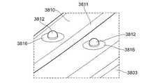
次に、駆動シャフト316の構造に関する様々な更なる特徴及び態様が説明される。上述のように、駆動シャフト316は、図10aによって示されるように、「T」字型の断面を有する細長い棒である。駆動シャフト316は、上述された切断機構に使用される切断刃340などの更に細長い部材を収容するのに適したスロット又は走路342をその長さに沿って含む。使用時に、切断刃340は、挟持部14間にクランプされた組織を切断するために切断刃340の遠位端を挟持部14間で駆動できるように、駆動シャフト316の長さに沿って滑動させられる。5. Drainage Holes Next, various additional features and aspects of the structure of the
時間の経過に伴って、血液及び組織が、器具1の遠位端内に、具体的には外側シャフト12及び駆動シャフト316の長さの先の方に、蓄積することがある。この血液及び組織の蓄積は、刃340を駆動シャフト316内で詰まらせて、器具1の、とりわけ切断機構の、機能性を低下させることがある。これに対抗するために、駆動シャフト318の遠位端の部分は、駆動シャフト316と刃340との間の接触領域を少なくし、それによって、血液及び組織が詰まる恐れがある表面積を低減させるために、切り抜かれる。 Over time, blood and tissue may accumulate in the distal end of
これらの切り抜き部分は、支えとなる基部と、分岐した側壁とを駆動シャフト316の遠位端が含むように、図10b〜cに示される細長い窓1000、1002などの孔であってよい。切り抜き部分は、分岐した側壁と、開いた底部とを遠位端が含むように、駆動シャフト316の基部まで伸びてもよい。これらの孔1000、1002によって可能になる排水の量を最大にするために、これらの孔は、駆動シャフト316の深さの50%を超えることが好ましい。 These cutouts may be holes such as
しかるがゆえに、これらの孔1000、1002は、中心走路342と、駆動シャフト316の外側との間に排水路を提供する。 Therefore, these
6. 回転ホイール及びスイッチ
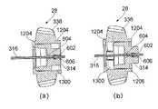
次に、サムホイール(本書では回転ホイールとも呼ばれる)28の動作に関する様々な更なる特徴及び態様が説明される。サムホイール28は、エンドエフェクタアセンブリ14が上に搭載された外側シャフト12をユーザが回転させることを可能にするために提供される。しかしながら、スペースを削減し、それによって、よりコンパクトな器具を作成するためには、サムホイール28の内部容積1300も、前述のクランプ機構の一部を形成する内側成形物314のための移動スペースを提供するために用いられる。このような配置によって、よりコンパクトな機構が得られる。6. Rotating Wheels and Switches Next, various additional features and aspects of the operation of the thumbwheel (also referred to herein as the rotating wheel) 28 will be described. The
より詳しくは、回転ホイール28(本書ではサムホイールとも呼ばれる)は、プラスチック製の歯様ホイールであり、その外径の周りに位置付けられた複数の波形部分336を有する。しかるがゆえに、サムホイール28は、歯の外観をしており、ユーザの親指を人間工学的に受けるように配置された波形の切り抜き部分を有する。これに関して、図13a、13b、及びとりわけ図14aに更に詳しく示されるように、波形部分は、サムホイール又は回転ホイール28が、総じて、ユーザから遠い遠位側の端での方がユーザに近い近位側の端でよりも広い僅かに切頭円錐型の形状であるように、使用時におけるサムホイールの回転面に対して角度を付けられる。波形部分336は、それぞれ、サムホイールの遠位端から近位端に伸びており、使用時にユーザの親指を受けるために湾曲している又は鞍様の形状である。図14aに詳しく示されるように、回転ホイール28を切頭円錐型にするための、波形部分336の角度付けは、器具のボディの角度に概ね一致する。図14aにおいて、破線は、ホイール28の端周りにおける波形336の角度付けを示しており、これは、ホイール周囲の地点における器具の外壁の角度に対して、及びとりわけホイールのすぐ前における器具の外壁部分の角度に対して接線方向であることがわかる。回転ホイールの外縁における角度付けされた波形がホイール周囲における器具の壁の角度付けに一致するこのような配置は、外科医によって容易に操作可能な快適で且つ人間工学的な設計を提供する。 More specifically, the rotary wheel 28 (also referred to herein as a thumbwheel) is a plastic tooth-like wheel having a plurality of
ホイール28の外径周りにおける波形部分336の数に関しては、一実施形態に示されるように、ホイールの外径周りに8個の波形部分が均等に分布している。その他の実施形態では、例えば、6個若しくは7個などの少ない数、又は9個若しくは10個などの多くの数などの、より少ない又はより多い数の波形部分が使用されてよい。もし、大きめのホイール28が用いられたならば、より多数の波形部分336が含まれてよく、反対に、小さめのホイールが用いられるならば、波形部分の数が少なくてよい。これに関して、各波
形部分336の実際の大きさは、波形部分がユーザの親指を快適に受けられるように人間工学的に選択されているゆえに、通常は、同じままであることが望ましい。Regarding the number of
図2に示されるように、器具内におけるサムホイール28の位置決めに関しては、回転ホイール又はサムホイール28は、スイッチ26の下で垂直な向きにされ、例えば駆動シャフト316の長手方向によって定められた長手方向軸に直交する方向にサムホイールから隔てられている。具体的には、ハンドスイッチ26は、このような長手方向軸に直交してサムホイール28も通過する軸の上に直接載っている。更に、図14a及び図14bに示されるように、スイッチ26は、比較的サイズが大きく、サムホイールの上方で、器具の上表面の片側からもう一方の片側にかけて広がっている。スイッチ26は、実際は湾曲しており、器具の外壁の湾曲した上表面に概ね一致し、ユーザが自身の親指でスイッチを捕らえて押せるように助けるために、その外表面上に膨らみ、溝、又はその他の隆起突出を有する。スイッチ26の表面積は、比較的大きく、3cm2を、又はひいては5cm2を超えている。これは、ユーザによるその人間工学的作動を可能にするための、大きな表面積を提供する。サムホイール28の真上におけるスイッチ26の垂直な向きも、人間工学的作動を可能にする。本書の他所で説明されるように、スイッチ26は、使用時に、エンドエフェクタ内に位置する組織の凝固のために、エンドエフェクタへのRF凝固信号の供給を引き起こすように作動する。As shown in FIG. 2, with respect to the positioning of the
スイッチ及びサムホイールの人間工学に関して、図35a及び図35bは、それぞれ異なる大きさの手を有する異なるユーザの2枚の写真である。図に示されるように、比較的表面積が大きいスイッチ26は、手の大きさが異なるユーザが、クランプハンドル22(及びもし必要であれば、刃トリガ24)を操作するのと同時に容易に操作することができる。 With respect to switch and thumbwheel ergonomics, FIGS. 35a and 35b are two photographs of different users, each with different sized hands. As shown in the figure, the
図12に戻り、前述のように、サムホイール28は、使用時に内側成形物314が中に受け入れられる内部空洞1300を有する。前述のように、内側成形物314は、内側成形物のチャンバ610を含み、その中にT字型の切り抜き部分1208を有し、該切り抜き部分には、前述のように、駆動シャフト316が通されて留め付けられる。内側成形物314は、ホイール28の内部空洞内にスナップ式に嵌り、図12、及び図29a、29bに示されるように、サムホイール28の円筒状内部空洞1300の外縁周りには、内側成形物314が空洞内に挿入されたらその内側成形物314を空洞内の適所に保持するために、フランジ1206が提供される。サムホイール28の内部空洞1300には、かみ合い部材1200も提供され、該部材は、円筒状の内側成形物314の外周沿いに提供された対応するかみ合い部材1202と相互に作用する。それぞれのかみ合い部材1200、1202は、サムホイール28と円筒状内側成形物314とが互いに対して正しく回転整合されたときに空洞1300の内表面沿いに円周方向に隣り合って組み合わさるそれぞれの隆起段差部分を含む。それぞれのかみ合い部材1200、1202は、円筒状内側成形物314が使用時にホイール28の内部空洞内で端から端へ滑動はしえるがホイール28内で回転はしえないように提供される。その代わりに、相互に作用するかみ合い部材1202、1200は、内側成形物314が回転ホイール28の回転に伴って回転ホイール28とともに回転するように機能する。このように、ユーザ28によって回転ホイール28に加えられた回転トルクは、エンドエフェクタを載せた駆動シャフト316を回転させるために、内側成形物314に伝達されて次いで駆動シャフトに伝達される。図29a及び図29bは、サムホイール28の内部空洞に挿入された内側成形物314を示しており、内側成形物314がどのようにしてホイール28の内部空洞1300内で軸方向に滑動しえるかを説明している。 Returning to FIG. 12, as described above, the
図13a及び図13bも、内側成形物314がどのようにしてホイール28の内部空洞1300内で移動できるかを更に詳細に示している。上述のように、駆動シャフト316
は、内側成形物314の中のT字型の孔1208に通され、駆動シャフトの端に提供されたスナップ式の突出したキャッチ部材又はラッチ部材602を通じて留め付けられる。要するに、ラッチ部材又はキャッチ部材602は、内側成形物314内のT字型の孔1208を通り抜けて次いで空洞を形成している内側成形物の第2の通路部分606に受け入れられる弾力性の金属タブの形態をとり、第2の通路部分606は、これらの弾力性タブが跳ね開くことを可能にし、そうして内側成形物内に駆動シャフトを留め付ける。内側成形物314は、次いで、サムホイール1208の内部空洞に押し込まれ、上述のように、スナップ式のタブ1206によって適所に保持される。内側成形物は、図13aに示されるように、ホイール28の遠位側の壁の内表面に突き当たるように、又はその移動の反対側の端において、ホイールの遠位側の縁にあるタブ1206に突き当たるように、内部空洞1300内で軸方向に移動してよい。したがって、内側成形物314は、サムホイール28の空洞内で軸方向にある程度の滑動を許容され、これは、上述のように、挟持部内に含まれた材料に対してユーザによって加えられる力を制御するための機構の一部として必要である。13a and 13b also show in more detail how the
Is passed through a T-shaped
サムホイール28の内部空洞内への内側成形物314のスナップ式嵌合特性は、装置の組み立てを大いに向上させ、装置の組み立てを大幅に容易に及びそれゆえに安価にする。同様に、図33に示されるように、サムホイールをケーシング内に位置決めするために、サムホイール28の遠位側の外壁1310は、装置のケーシングからの突出として提供された支持内壁1320と同心であるとともに揃えられている。これも、ケーシング内におけるホイール28の容易で且つ正確な組み立て及び位置決めを可能にする。 The snap fit property of the
7. 駆動シャフトの回転制御
上述のように、エンドエフェクタ14を上に有するシャフト12は、組織の切断及び凝固のためにエンドエフェクタが所望の回転位置へ動かされることを可能にする。しかしながら、エンドエフェクタへの配線接続が、一方向に極端に回転されているシャフトからの過度なひずみ下に置かれて配線が巻き上がる、捻じれる、又は過度なひずみを受けることがないようにするためには、シャフト12の回転を制御するための機構が必要であり、特に、回転の量を制限しそれによって配線が受ける過度なひずみを阻止するための機構が必要である。また、シャフト12の回転のポシティブ制御の提供は、使用時における器具の人間工学的経験を向上させ、ユーザの知覚の質を高める。7. Rotational Control of Drive Shaft As described above, the
一実施形態においてシャフトの回転制御を提供するためには、図15a及び図15b、並びに図16a〜dに示されるような配置が用いられる。図15を参照すると、ここでは、サムホイール28が、その近位側表面(即ち、ユーザに面している、後方を向いた面)上に波形部分36を提供され、近位側表面から僅かに突出するリング1506が、ホイール28の軸と同心に配置される。リング1506は、使用時に、ガイドストッパー1502、1504上に載っており、これらは、外側ケーシングの内表面からの突出であり、リング1506の外周に接触するように上方に突き出している。ストッパー1502は、リングの軸に対するケーシング上におけるそれらの位置決めゆえにストッパー1504よりも小さいが、ストッパー1502、1504は、ともに、角度付けされたガイド上面1510、1512(図15aを参照)をそれぞれ有する。これらのガイド上面は、リング1506の外周表面に接触してサムホイールの一部を形成し、サムホイールをその回転において支持及び誘導する。 In order to provide rotational control of the shaft in one embodiment, the arrangements shown in FIGS. 15a and 15b, and FIGS. 16a-d are used. Referring to FIG. 15, here the
加えて、ガイド機能を提供するために、ストッパー1502、1504は、これらのストッパーの角度位置を超えるサムホイールの回転を阻止するためのストップ部材としても機能する。これに関連して、リング1506は、そこから半径方向に伸びる矩形のストップ突出1500を提供されている。サムホイール28が回転されるのに伴って、ストップ突出1500は、ストッパー1502、1504のそれぞれのストップ面1514、15
16に突き当たる。ストップ面は、矩形のストップ突出1500がストップ面に突き当たる角度に位置決めされたときにストップ突出に平行であるように角度を付けられる。In addition, in order to provide a guide function, the
It hits 16. The stop surface is angled so that it is parallel to the stop protrusion when the
上述のように配置されたストップ突出1502、1504は、ストッパー1500からストッパー1502への既知の量のホイール28回転を提供できるような配置及び長さである。図15a及び図15bに示された目下説明されている配置では、ストッパー1502、1504は、サムホイールがストップからストップへ270度回転することを可能にできるように、ケーシング上に間隔をあけて位置決めされる。回転の量は、ストッパー間の距離を増加又は減少させることによって僅かに変化させることができ、それに応じて、ストッパーは、ホイールとストッパーとが尚も実質的に垂直に出会えるように、ガイド面及びストップ面の長さと角度とを適応される。例えば、ストッパーは、250度から300度のホイールの角度回転を提供するような位置決め及び形状であってよい。 The
上記は、サムホイールに(及び次いでサムホイールを通じてシャフトに)加えられる回転制御を説明している。図16a〜dは、反対側のシャフト端においてシャフト成形物320を使用してシャフトに作用する更なる回転制御機構を示している。ここで、シャフト成形物320は、そこから突き出す矩形のストップ部材1600を提供されている。外側ケーシングの内表面は、更に、それぞれの成形ストッパー1602、1604を提供され、これらのストッパーは、シャフト成形物320のそれぞれの角度位置においてそれぞれの平行ストップ表面を矩形ストップ部材1600に臨ませるそれぞれのストップ表面を提供する段差構造の形で示されている。図に示された例では、成形ストッパーは、ケーシング上に位置決めされ、エンドエフェクタを載せているシャフト12の、ストップからストップへの270度の回転を許容するために、それぞれのストップ表面をストップ部材1600に臨ませる。その他の実施形態では、成形されたストッパー1602、1604は、例えば180度から360度、又は更に好ましくは250度から300度、又は最も好ましくは270度などの、より多い又は少ない量の回転を提供するために、成形物320のその他の回転角度位置においてストップ表面をストップ部材1600に臨ませるように位置決めされてよい。 The above describes the rotational control applied to the thumbwheel (and then to the shaft through the thumbwheel). 16a-d show a further rotation control mechanism that acts on the shaft using the
サムホイール28及びシャフト成形物320に提供されたそれぞれの回転制御機構は、互いに独立に提供されてよい。即ち、任意の特定の実施形態において、これらの両方の回転機構が提供される必要はなく、シャフトの回転制御を提供するために、一方のみ又は別の一方のみが提供されてもよい。しかしながら、装置の動作及び知覚の質の観点からすると、両方の回転制御機構が同じ装置内に提供されて、いずれの回転方向にもそれぞれの同地点で回転を停止させるように位置合わせされると有利である。このような配置は、シャフトの回転がハンドル部分10の両端で独立に停止することを意味しており、ストップによって表される許容限界を超える望ましくない更なるシャフト回転をユーザが強いることが、非常に困難になる。 The respective rotation control mechanisms provided for the
図36及び図37には、代替の回転制御機構が示されている。図36は、再びシャフト成形物320を示しており、ただし、ここでは、成形物は、リング3220を提供され、該リング上には、そこから半径方向に突き出す主要な矩形ストップ部材3202と、リングの周に沿って実質的に等角度間隔で好ましくは直交位置に位置決めされた補助的な位置マーカ部材3204、3206、3208とが搭載されている。補助的な位置マーカ部材3204、3206、3208は、ストップ面3212、3214に突き当たるのに十分な大きさではない小さい隆起突出を構成する。 36 and 37 show an alternative rotation control mechanism. FIG. 36 again shows the
ストップ面3212、3214は、外側ケーシングに一体の成形物として提供され、ここでは、シャフト成形物320が180度回転されることを許容できるように位置決めされる。これに関して、ストップ部材320は、回転範囲の両極において、シャフト成形物
の更なる回転を防ぐために、ストップ面3212、3214に突き当たる。したがって、図36a〜cに示されるように、シャフト12を載せているシャフト成形物320は、エンドエフェクタが必要に応じて回転式に位置決めされることを可能にするために、180度回転されてよい。The stop surfaces 3212, 3214 are provided as an integral part of the outer casing, where the
また、弾力性の突出3216も提供され、該突出は、その先端がリング3220の外周表面に接触するようにストップ面3214形成成形物から上向きに突出している実質的に三角形の断面のプラスチック突出を含む。小さい隆起突出の形をしている補助的な位置マーカは、シャフト成形物320の回転に伴ってこの弾力性突出の先端に押し付けられ、弾力性突出の先端を、対応する突出が先端を通過することを可能にするためにその静止位置から外れさせる。この動作の効果は、機構を回転させて、隆起突出を、弾力性突出の先端に接触する回転位置を通過させるために、ユーザが更なる力を加えなければならないという意味で、何らかのユーザフィードバックを提供することである。なぜならば、弾力性突出の先端を撓ませて、隆起突出が先端を通過することを可能にするためには、十分な力が提供されなければならないからである。これの結果は、シャフトを回転させて隆起突出の回転位置を通過させるために必要とされる力の増加をユーザが感じ取ることであり、したがって、ユーザは、直感的に、シャフトの及びそれゆえにエンドエフェクタの回転位置に関する示唆を提供される。このような触覚的フィードバック機構は、こうして、ユーザに優しく且つ容易な装置操作を可能にする。 Also provided is an
図37は、図36の機構のための、対応するサムホイール28を示している。ここでは、サムホイールも、サムホイールの周囲に90度の間隔で直交に配置されたそれぞれの小さいストップを提供されている。シャフト成形物320の場合と同様な触覚的フィードバックを提供するために、弾力性突出3216と同様な、ケーシングから突き出した機構が提供されてよい。このような配置では、シャフトの回転位置に関する触覚的フィードバックがハンドルの両方の端から提供され、したがって、ユーザの装置知覚が向上される。 FIG. 37 shows the corresponding
8. 配線
次に、ハンドル2内における配線に関する様々な更なる特徴及び態様が説明される。上述のように、何らかの適切な回路構成を通じてエンドエフェクタアセンブリ14の中の電極を作動させるためのRF信号を活性化及び非活性化するために、例えば小型プリント回路基板(PCB)338上の2つの侵入保護スイッチなどのスイッチボタン26が提供される。図17に示されるように、PCB338は、ジェネレータ(不図示)からのRF出力を受信するための接続コード1700、並びにRF電流を挟持部14の中の電極に供給するための、例えば1本は活性電極のための及びもう1本は戻り電極のための電気配線1702、1704に接続される。8. Wiring Next, various further features and aspects of wiring within the
組み立ての際は、電極からの配線1702、1704が、駆動シャフト316に並行して外側シャフト12を遡ってシャフト成形物320に至るように引かれる。図9bに示されるように、シャフト成形物320は、外側シャフト12を受け入れるための開口912を遠位端に有する円筒状の又はたる型のコンポーネントである。外側シャフト12は、例えば、シャフト成形物320内の対応する切り込み902と協働するスナップ式のタブ900によって、シャフト成形物320に取り付けられる。したがって、もし、シャフト成形物320が回転すると、それとともに、外側シャフト12も回転する。シャフト成形物320は、更に、近位端に更なる孔914を含み、該孔914は、駆動シャフト316を受け入れられるように「T」字型の形状を有し、駆動シャフト316は、シャフト成形物320の内部空洞1802を通って外側シャフト12の長さにわたって伸びる。しかるがゆえに、駆動シャフト316は、シャフト成形物320内で及び外側シャフト12内で滑動することができ、しかしながら、駆動シャフト316の回転運動は、シャフト成形物320に及びそれに続いて外側シャフト12に伝達される。 During assembly, the
図18aに示されるように、電極配線1702、1704は、シャフト成形物320のボディ1804の上に及び周りに巻き付けられる前に、シャフト成形物320の壁にあいた開口1800を通して内部空洞1802から引き出される。配線1702、1704をこのようにシャフト成形物320に巻き付けることによって、配線1702、1704は、器具1の残りの部分を組み立てるときに配線1702、1704が邪魔になる事態が回避されるように、コンパクトな構成に維持される。更に、配線1702、1704をシャフト成形物320に巻き付けるということは、シャフト成形物320が駆動シャフト316とともに回転するのに伴って、配線1702、1704が引き寄せられて短絡することなく上記回転とともに配線1702、1704が巻きを解かれる及び再び巻かれることを意味する。具体的には、このように配線1702、1704を巻き付けることによって、図15a〜b及び図16a〜dを参照にして説明されるように、最大で270度の回転が可能になる。 As shown in FIG. 18a, the
電気配線1702、1704は、次いで、ケーシング20の頂部に沿って引き渡される。これに関して、クラムシェル成形物の1つ300は、活性配線1702及び戻り配線1704を侵入保護スイッチ338の配線1908、1910に接続する配線コンタクト1904、1906を収容するための、2つの直列に配置されたポケット1900、1902を提供されている。したがって、全ての電気配線1702、1704、1908、1910は、各ポケット1900、1902内に1つのコンタクト1904、1906のみが収容されるように、ポケット1900、1902の中及び周囲において経路設定される。配線の経路設定は、1組の配線1702、1910をポケット1900、1902の外周りに方向付けるガイド部分1912、1914、1916によって補助される。各ポケット内では、活性配線1702が配線1908と長手方向に揃えられ、戻り配線1704が配線1910と長手方向に揃えられる。 The
その結果、2つの配線コンタクト1904、1906は、各ポケット1900、1902に一方のコンタクトのみを通せるように長手方向に分離され、それによって、各コンタクト1904、1906と配線との間に物理的障壁が提供される。これは、コンタクト1904、1906自体によって引き起こされるあらゆる配線の絶縁損傷のリスクを防ぐ。 As a result, the two
配線1702、1704、1908、1708は、全て、そのそれぞれのポケット1900、1902に、ポケットの壁にあいた小開口1918、1920、1922、1924を通って進入する。好ましくは、孔1918、1920、1922、1924の寸法は、1本の電気配線のみが通り抜けられる寸法である。実質的に密封されたハウジングを形成できるように、相対するクラムシェル成形物302も、ポケット1900、1902内にコンタクト1904、1906を保持するための対応するリブ機構(不図示)を含む。これは、外側シャフト12を経てケーシング20内へ進みその結果としてコンタクト1904、1906による回路の短絡を引き起すかもしれないあらゆる流体からコンタクト1904、1906を保護するためにポケット1900、19200の浸透性を最小限に抑えるために、重要である。
9. エンドエフェクタアセンブリ
次に、装置に使用されてよいエンドエフェクタアセンブリの例が説明される。説明される例は、完全を期すために与えられるものであり、駆動シャフト316によって駆動可能でありさえすれば、その他の設計のエンドエフェクタが器具に使用されてもよいことが、理解されるべきである。要するに、本発明の実施形態は、本書で説明される特定のエンドエフェクタに限定されず、その他の設計のエンドエフェクタが使用されてもよい。9. End Effector Assembly Next, an example of an end effector assembly that may be used in the device will be described. It should be understood that the examples described are given for perfection and that end effectors of other designs may be used in the instrument as long as they are driveable by the
図38〜44は、封止電極の一方又は両方に導電性ストップ部材が配されている器具の
例を示している。図38を参照すると、全体を3801で示されているエンドエフェクタは、枢軸3804を中心にして下方挟持部3803に枢動式に接続された上方挟持部3802を含む。上方挟持部3802の近位端に、フランジ3805が存在する一方で、下方挟持部3803の近位端には、フランジ3806が存在する。フランジ3805、3806は、(駆動機構(不図示)による)駆動ピン3808の近位側及び遠位側における動きが挟持部3802、3803を開位置と閉位置との間で枢動させるように、それぞれ、駆動ピン8が通るスロット3807を有する。FIGS. 38 to 44 show an example of an instrument in which a conductive stop member is arranged on one or both of the sealing electrodes. With reference to FIG. 38, the end effector, which is shown entirely at 3801, includes an
上方挟持部3802の内向き面上に、金属製のシム3809が存在する一方で、下方挟持部3803の内向き面上には、金属製のシム3810が存在する。挟持部3802、3803がその閉位置へ枢動するときは、金属製のシム3809、3810は、それらの間に組織(不図示)を把持するために互いに近接近する。 A
上方のシム3809は、その長さにわたる長手方向の溝(図38では見えていない)を例外として、概ね平面状の表面を有する。下方のシム3810は、対応する溝3811を有し、シム3809、3810の中の溝は、切断刃(不図示)の長手方向移動に適応している。下方シム3810は、シムの長さに沿って配されて溝3811の両側に位置する複数の金属製ストップ部材3812も提供される。ストップ部材3812は、図39及び図40を参照にして、次に更に詳しく説明される。 The
各金属製ストップ部材3812は、ストップ要素3813の上部ドームによって構成され、該ドームは、絶縁部材3814によって、該絶縁部材がストップ要素3813を封入してシムの残りの部分から隔離するように包み込まれる。各絶縁部材3814及びストップ要素3813は、絶縁部材の上方部分が各ストップ部材3812を取り巻く絶縁リング3816を形成するように、シム3810内に存在する対応する孔の中に位置決めされる。 Each
挟持部3802、3803が、(図40に示されるように)それらの閉位置へ動かされると、ストップ部材3812は、上方シム3809に接触し、上方シムと下方シムとの間に20μmから約350μm(0.00079インチから約0.014インチ)の分離を維持する。使用時には、シム3809と3810との間に凝固のための電気手術電圧が供給され、シム間の分離は、挟持部材3802と3803との間に把持される組織の効果的な封止を保証する。その一方で、ストップ部材3812は、それらがシム3810の残りの部分と同じ電位を帯びないように、電気的に隔離されているので、シム間の電気的短絡は、回避される。金属製のストップ部材3812は、剛性であり、シム表面の一貫した分離を可能にする一方で、ストップ要素3813がいつ上方のシム3809に接触するかを検出するためにストップ要素3818の電位を監視し、挟持部が閉じたとの示唆を与えることができるという点で、実用的である。 When the
図41〜43は、金属製ストップ部材3812が、ストップ部材を取り巻く絶縁部材の提供を伴うことなく下方シム3810上に直接搭載される代替の配置を示している。この配置では、各ストップ部材に対応するように、上方シム3809に絶縁部材3817が提供される。このようにすると、挟持部3802と3803とが閉じられたときに、絶縁部材3817によって、上方シム3809と下方シム810との間に電気的短絡がないことが保証される。金属製ストップ部材3812は、挟持部間に把持されている組織を封止するために電気手術エネルギが加えられる最中に、挟持部材間の適切な分離が維持されることを保証する。 FIGS. 41-43 show an alternative arrangement in which the
最後に、図44は、金属製ストップ部材3812が再び下方シム3810上に直接搭載される更なる代替配置を示している。この配置では、各ストップ部材の向かい側に金属製
のアンビル3818が配置され、各アンビル3818は、上方シム3809の残りの部分から隔離するために、絶縁部材3819に取り囲まれる。挟持部が閉じられるときは、ストップ部材3812と金属製アンビル3818との間に金属どうしの接触が生じ、ここでもやはり、アンビルの隔離によって、シム3809と3810との間の電気的短絡が回避されることが保証される。ここでもやはり、各金属製アンビルがいつ下方シムの電位を帯びて、挟持部が閉じたことを示唆するかを検出するために、各金属製アンビルの電位を監視することができる。Finally, FIG. 44 shows a further alternative arrangement in which the
10. 電気手術システム
次に、図45を参照すると、使用時における器具1は、制御可能な高周波(RF)源を中に有する電気手術ジェネレータ4500に接続されるとされ、高周波源は、器具1のエンドエフェクタの電極を通じて与えられたときに組織を凝固させる又は封止するRF凝固信号を生成する。電気手術ジェネレータ4500は、ジェネレータがオン及びオフにされることを可能にするための、並びに制御対象とされている器具1にRF凝固信号の電力が供給されることを可能にするための、それぞれの制御入力スイッチ4504、4502を含む。これらに関して、電気手術ジェネレータ4500は、従来通りである。10. Electrosurgical System Next, referring to FIG. 45, the
器具1は、使用時に、制御・電力ライン4506によってジェネレータ4500に接続される。制御・電力ラインは、前述の内部配線を通じて器具1のエンドエフェクタにRF信号が供給されることを可能にするための、及びRF凝固信号を器具1に出力するように電気手術ジェネレータに指示するために器具1のスイッチ26から制御信号が受信されることを可能にするための、別々の制御ラインを内包している。使用時に、外科医は、オン−オフスイッチ4504を通じてジェネレータを作動させ、ボタン4502を使用して、内部RF源によって生成される凝固又は封止のための信号強度を選択する。器具を使用した外科手術中、エンドエフェクタにおいて封止又は凝固のためのRF信号が必要とされるときは、外科医は、ジェネレータを制御してこのような信号を生成させるために器具上のスイッチ26を押し、生成されたRF信号は、次いで、電気ライン4506を通じてエンドエフェクタに引き渡される。要するに、使用時におけるスイッチ26の押圧が、エンドエフェクタ内に内包された適切な電極へのRF凝固又は封止信号の供給を引き起こす。 The
11. まとめ
したがって、以上の全てを考慮すると、本発明の実施形態は、高度な電気手術鉗子器具であって、ユーザによる容易で且つ人間工学的な片手操作を可能し、エンドエフェクタの回転柔軟性を提供し、把持されている組織に対してエンドエフェクタによって加えられる力を制御して、過度な力が加えられることを阻止し、把持されている組織を電気手術によって凝固又は封止させつつ、尚も簡便な機械的切断を同時に可能にする、電気手術鉗子器具を提供する。更に、器具は、それぞれの内部活性化機構内において利用可能なスペースの効率的使用を通じてコンパクトな器具を提供しつつ、尚も構築が単純で且つ低コストであるように設計されている。11. Summary Therefore, considering all of the above, an embodiment of the present invention is an advanced electrosurgical forceps instrument that allows easy and ergonomic one-handed operation by the user and provides rotational flexibility of the end effector. However, the force applied by the end effector to the gripped tissue is controlled to prevent excessive force from being applied, and the gripped tissue is coagulated or sealed by electrosurgery while still being coagulated or sealed. Provided is an electrosurgical forceps instrument that enables simple mechanical cutting at the same time. Moreover, the instruments are designed to be simple and inexpensive to build, while providing compact instruments through efficient use of the space available within each internal activation mechanism.
当業者には、追加、削除、又は置換のいずれによってであれ、上述された実施形態に対する様々な更なる変更が、更なる実施形態を提供するために明らかであり、これらの更なる実施形態は、いずれも、添付の特許請求の範囲によって網羅されることを意図している。 Various further changes to the embodiments described above, whether by addition, deletion, or replacement, are apparent to those skilled in the art to provide further embodiments, and these further embodiments are , Both are intended to be covered by the appended claims.
Claims (27)
Translated fromJapaneseハンドルと、
前方方向と後方方向とに中心軸を定め、前記ハンドルから前記前方方向に遠位端まで伸びている細長いシャフトと、
前記細長いシャフトの前記遠位端に位置決めされたエンドエフェクタと、
前記細長いシャフト内に配置され、近位端から遠位端まで延びる刃アセンブリであって、該遠位端に、前記エンドエフェクタに近接して位置する切断刃が位置付けられ、該近位端で、前記ハンドル内のコンポーネントに接続されている刃アセンブリと、
前記ハンドル上に位置付けられ、第1の位置と第2の位置との間で可動であるトリガ機構であって、前記トリガ機構の該第1の位置から該第2の位置への動きが、前記エンドエフェクタに対して前記切断刃を長手方向に前進させるために前記刃アセンブリの長手方向移動を引き起こす、トリガ機構と、
を備え、
前記トリガ機構は、
近位端と、遠位端とを含み、該近位端と該遠位端との間に位置付けられた第1の枢軸を中心として枢動可能であるトリガアームと、
近位端と、遠位端とを含み、該近位端が第2の枢軸によって前記トリガアームの前記遠位端に接続されているフレームと、
第3の枢軸によって前記フレームの前記遠位端に直接的に接続されたカラーと、
を含み、
配置は、前記トリガ機構の前記第1の位置から前記第2の位置への前記動きが、前記第1の枢軸を中心として前記トリガアームを枢動させて前記フレームを前記前方方向に移動させ、それによって前記カラーを前記トリガアームに対して移動させることによって構成されるような配置であり、前記カラーは、更に、前記カラーの移動が前記刃アセンブリの前記長手方向移動を引き起こすように前記コンポーネントに接続され、
前記第1の枢軸及び前記第2の枢軸は、前記細長いシャフトの前記中心軸からずれて、該中心軸の両側にあり、
前記第3の枢軸は、前記細長いシャフトの前記中心軸上に位置付けられ、且つ、前記前方方向において前記第2の枢軸の前方にある、
手術器具。Surgical instrument
With the handle
An elongated shaftthat defines a central axis in the anterior and posterior directions and extends from the handle to thedistal end in the anterior direction.
An end effector positioned atthe distal end of the elongate shaft,
Disposed within the elongateshaft, a blade assemblyextending from the proximal end to the distal end, tothe distal end, the cutting edge locatedproximate to the end effector is positioned atthe proximal end, With the blade assembly connected to the component in the handle
Positioned on said handle, a trigger mechanism is movable between a first position and a second position, movement tosaid second position fromsaid first position of said trigger mechanism, wherein A trigger mechanism that causes longitudinal movement of the blade assembly to advance the cutting blade longitudinally with respect to the end effector.
With
The trigger mechanism is
A proximal end, and a distal end, and the trigger arm is pivotable about a first pivot positioned betweensaid proximal end andsaid distal end,
A proximal end, and a distal end, and a frameto which the proximal end is connected to the distal end of thetrigger arm by a second pivot,
With a collar directly connected to the distal end of the frame by a third axis,
Onlyincluding,
Arrangement, the motion tothe second position fromsaid first position of said trigger mechanism, thereby pivoting the trigger armto move the framein the forward direction about said firstpivot, The arrangement is such that the collar is thereby moved relative to thetrigger arm, and the collar is further attached to the component such that the movement of the collar causes the longitudinal movement of the blade assembly. Connected,
The first pivot and the second pivot are offset from the central axis of the elongated shaft and are located on both sides of the central axis.
The third pivot is positioned on the central axis of the elongated shaft and is in front of the second pivot in the forward direction.
Surgical instruments.
前記トリガアームの前記枢動は、前記トリガアームの前記近位端を前記後方方向に、且つ前記トリガアームの前記遠位端を前記前方方向に移動させる、手術器具。The surgical instrument according to claim 1.
The pivoting of thefront Symbol trigger arm, the proximal end of theprevious SL rear directionof the trigger arm, is and moving the distal endof the trigger armbefore Symbol forward direction, the surgical instrument.
前記トリガアームの前記枢動は、前記カラーを前記前方方向に移動させる、手術器具。The surgical instrument according to claim 2.
Wherein pivoting of said trigger arm moves the collarbefore Symbol forward direction, the surgical instrument.
前記フレームは、H字型のコンポーネントを含む、手術器具。The surgical instrument according to any one of claims 1 to 3.
The frame is asurgical instrument containing an H -shaped component.
前記H字型のフレームは、第1の及び第2の長手方向サイドアームを、それらの間の突っ張りとともに含む、手術器具。The surgical instrument according to claim 4.
The H-shaped frame is a surgical instrument that includes first and second longitudinal sidearms with a strut between them.
前記トリガアームの前記遠位端は、前記第1のサイドアームの近位端と、前記第2のサイドアームの近位端との間に位置付けられる、手術器具。The surgical instrument according to claim 5.
A surgical instrument in which the distal end of the trigger arm is located between the proximal end of the first sidearm and the proximal end of the second sidearm.
前記第1の及び第2のサイドアームは、それらに対して前記トリガアームが枢動可能であるように、それらの近位端にそれぞれ軸受けを有する、手術器具。The surgical instrument according to claim 6.
The first and second sidearms are surgical instruments, each having a bearing at its proximal end so that the trigger arm is pivotable with respect to them.
前記トリガアームは、前記第1の及び第2のサイドアームの前記近位端の前記軸受けにスナップ式に嵌ることができる第1の及び第2のラグを有する、手術器具。The surgical instrument according to claim 7.
A surgical instrument, wherein the trigger arm has first and second lugs that can be snapped onto the bearing at the proximal end of the first and second sidearms.
前記カラーは、前記第1のサイドアームの遠位端と、前記第2のサイドアームの遠位端との間に位置付けられる、手術器具。The surgical instrument according to any one of claims 5 to 8.
The collar is a surgical instrument positioned between the distal end of the first sidearm and the distal end of the second sidearm.
前記第1の及び第2のサイドアームは、前記フレームが前記カラーに対して枢動可能であるように、それらの遠位端にそれぞれ軸受けを有する、手術器具。The surgical instrument according to claim 9.
The first and second sidearms are surgical instruments, each having a bearing at its distal end so that the frame is pivotable with respect to the collar.
前記カラーは、前記第1の及び前記第2のサイドアームの前記遠位端の前記軸受けにスナップ式に嵌ることができる第1の及び第2のラグを有する、手術器具。The surgical instrument according to claim 10.
The surgical instrument, wherein the collar has first and second lugs that can be snapped onto the bearing at the distal end of the first and second sidearms.
前記トリガ機構が前記第2の位置にあるときは、前記トリガ機構が前記第1の位置にあるときと比べて、前記第2の枢軸は、より前記中心軸に近い、手術器具。The surgical instrument according to any one of claims 1to 11.
When the trigger mechanism is inthe second position, than when the trigger mechanism is inthe first position, the second pivot axis, closer to the central axis, the surgical instrument.
前記トリガ機構は、前記第1の位置へ付勢される、手術器具。Claims 1 a surgical instrument according to any one of 12,
The trigger mechanism is biased tosaid first position, the surgical instrument.
バネを備え、前記バネは、前記トリガ機構を前記第1の位置へ付勢するために、一端を前記トリガアームに及びもう一端を前記カラーに取り付けられる、手術器具。A surgical instrument according to claim 13,
A spring, said spring, to bias the trigger mechanism tothe first position, is attached at one end to the trigger arm and the other end to the collar, the surgical instrument.
前記トリガアームは、少なくとも1つの孔を含み、前記バネは、前記トリガアームに取り付けられる前に、前記少なくとも1つの孔を通る、手術器具。A surgical instrument according to claim 14,
A surgical instrument in which the trigger arm comprises at least one hole and the spring passes through the at least one hole before being attached to the trigger arm.
前記バネは、前記中心軸の下方に位置付けられる、手術器具。A surgical instrument according to claim 14 or 15,
The spring is positioned belowthe centric shaft surgical instrument.
前記第3の枢軸は、前記中心軸と同じ高さに位置付けられる、手術器具。The surgical instrument according to claim16.
It said third pivot is positioned at the same height as thesaid centric shaft surgical instrument.
前記ハンドル上に位置付けられた回転可能サムホイールを備え、前記サムホイールの回転が、前記エンドエフェクタの対応する回転を引き起こす、手術器具。The surgical instrument according to any one of claims 1 to17, further
A surgical instrument comprising a rotatable thumbwheel positioned on the handle, wherein the rotation of the thumbwheel causes the corresponding rotation of the end effector.
前記エンドエフェクタは、1対の互いに対向する第1の及び第2の挟持部材を含み、前記切断刃は、これらの挟持部材間で長手方向に平行移動可能である、手術器具。The surgical instrument according to any one of claims 1 to18.
A surgical instrument, wherein the end effector includes a pair of opposing first and second holding members, the cutting blade being vertically translatable between these holding members.
前記第1の及び第2の挟持部材は、湾曲した走路を形成できるように、湾曲されている、手術器具。The surgical instrument according to claim19.
The first and second holding members are surgical instruments that are curved so as to form a curved track.
前記切断刃は、少なくとも2つの領域で形成され、第1の領域は、横方向における柔軟性が第2の領域よりも大きく、前記第2の領域よりも遠位側に位置付けられる、手術器具。A surgical instrument according to claim 20,
A surgical instrument in which the cutting blade is formed of at least two regions, the first region having greater lateral flexibility than the second region and located distal to the second region.
前記切断刃の少なくとも一部は、低摩擦コーティングでコーティングされる、手術器具。A surgical instrument according to claim 20 or 21,
Surgical instruments in which at least a portion of the cutting blade is coated with a low friction coating.
駆動シャフトを備え、前記駆動シャフトは、その遠位端で前記エンドエフェクタに及びその近位端で作動機構に接続され、前記作動機構は、前記駆動シャフトの長手方向移動を引き起こすように、第1の位置と第2の位置との間で可動であり、前記駆動シャフトの前記長手方向移動は、前記挟持部材のうちの少なくとも一方を、もう一方に相対的に、前記挟持部材が互いに間隔をあけた関係で配される第1の開位置から、前記挟持部材が協働してそれらの間に組織を把持する第2の閉位置へ動かす、手術器具。The preceding claims19 a surgical instrument according to any one of 22, further,
A first drive shaft is provided such that the drive shaft is connected to the end effector at its distal end and to an actuating mechanism at its proximal end, the actuating mechanism causing longitudinal movement of the drive shaft. Movable between the position and the second position, the longitudinal movement of the drive shaft causes the sandwiching members to be spaced apart from each other relative to at least one of the sandwiching members. A surgical instrument that moves from a first open position arranged in a relationship to a second closed position in which the holding members work together to grip tissue between them.
前記駆動シャフトは、前記刃アセンブリを受け入れるための細長いスロットを含み、前記トリガ機構のその第1の位置からその第2の位置への動きは、前記切断刃を前記細長いスロットに沿って前記第1の挟持部材と前記第2の挟持部材との間で長手方向に前進させる、手術器具。A surgical instrument according to claim 23,
The drive shaft includes an elongated slot for receiving the blade assembly, and movement of the trigger mechanism from its first position to its second position causes the cutting blade to move along the elongated slot. A surgical instrument that advances in the longitudinal direction between the holding member of the above and the second holding member.
前記エンドエフェクタは、1つ以上の電極を含み、前記器具は、前記器具を電気手術ジェネレータに接続することができる電気接続を含む、手術器具。Claims 1 a surgical instrument according to any one of 24,
The end effector comprises one or more electrodes, the instrument comprising an electrical connection capable of connecting the instrument to an electrosurgical generator.
前記トリガアーム及び前記フレームの長さ、並びに前記第1の及び第2の枢軸の位置は、前記トリガ機構に加えられる力が一定である場合に、前記エンドエフェクタによって加えられる力がその運動範囲にわたって変化するような長さ及び位置である、手術器具。The surgical instrument according to any one of claims 1 to25.
The length of the trigger arm and the frame, and the positions of the first and second pivots are such that when the force applied to the trigger mechanism is constant, the force applied by the end effector extends over the range of motion. Surgical instruments of varying length and position.
前記配置は、前記トリガ機構に加えられる力が一定である場合に、前記エンドエフェクタによって加えられる力が、前記エンドエフェクタがその運動範囲の第1の部分にわたって動くのに伴って減少し、次いで、その運動範囲の第2の部分にわたって動くのに伴って増加するような配置である、手術器具。The surgical instrument according to claim26.
The arrangement is such that when the force applied to the trigger mechanism is constant, the force applied by the end effector decreases as the end effector moves over the first portion of its range of motion, and then A surgical instrument that is arranged to increase as it moves over a second portion of its range of motion.
Applications Claiming Priority (4)
| Application Number | Priority Date | Filing Date | Title |
|---|---|---|---|
| GB1600546.4 | 2016-01-12 | ||
| GBGB1600574.6AGB201600574D0 (en) | 2016-01-12 | 2016-01-12 | Electrosurgical device |
| GBGB1600546.4AGB201600546D0 (en) | 2016-01-12 | 2016-01-12 | Electrosurgical device |
| GB1600574.6 | 2016-01-12 |
Publications (2)
| Publication Number | Publication Date |
|---|---|
| JP2017200563A JP2017200563A (en) | 2017-11-09 |
| JP6901205B2true JP6901205B2 (en) | 2021-07-14 |
Family
ID=55445903
Family Applications (12)
| Application Number | Title | Priority Date | Filing Date |
|---|---|---|---|
| JP2017002908AActiveJP6915947B2 (en) | 2016-01-12 | 2017-01-11 | Electrosurgical equipment |
| JP2017002900AActiveJP6888957B2 (en) | 2016-01-12 | 2017-01-11 | Electrosurgical equipment |
| JP2017002907AActiveJP6887809B2 (en) | 2016-01-12 | 2017-01-11 | Electrosurgical equipment |
| JP2017002901AActiveJP6915945B2 (en) | 2016-01-12 | 2017-01-11 | Electrosurgical equipment |
| JP2017002910AActiveJP6943368B2 (en) | 2016-01-12 | 2017-01-11 | Electrosurgical equipment |
| JP2017002904AActiveJP6901205B2 (en) | 2016-01-12 | 2017-01-11 | Electrosurgical equipment |
| JP2017002905AActiveJP6896433B2 (en) | 2016-01-12 | 2017-01-11 | Electrosurgical equipment |
| JP2017002899AActiveJP7140318B2 (en) | 2016-01-12 | 2017-01-11 | electrosurgical device |
| JP2017002902AActiveJP6888802B2 (en) | 2016-01-12 | 2017-01-11 | Electrosurgical equipment |
| JP2017002903AActiveJP7040868B2 (en) | 2016-01-12 | 2017-01-11 | Electrosurgical equipment |
| JP2017002909AActiveJP7107626B2 (en) | 2016-01-12 | 2017-01-11 | electrosurgical device |
| JP2017002906APendingJP2017164485A (en) | 2016-01-12 | 2017-01-11 | Electrosurgery device |
Family Applications Before (5)
| Application Number | Title | Priority Date | Filing Date |
|---|---|---|---|
| JP2017002908AActiveJP6915947B2 (en) | 2016-01-12 | 2017-01-11 | Electrosurgical equipment |
| JP2017002900AActiveJP6888957B2 (en) | 2016-01-12 | 2017-01-11 | Electrosurgical equipment |
| JP2017002907AActiveJP6887809B2 (en) | 2016-01-12 | 2017-01-11 | Electrosurgical equipment |
| JP2017002901AActiveJP6915945B2 (en) | 2016-01-12 | 2017-01-11 | Electrosurgical equipment |
| JP2017002910AActiveJP6943368B2 (en) | 2016-01-12 | 2017-01-11 | Electrosurgical equipment |
Family Applications After (6)
| Application Number | Title | Priority Date | Filing Date |
|---|---|---|---|
| JP2017002905AActiveJP6896433B2 (en) | 2016-01-12 | 2017-01-11 | Electrosurgical equipment |
| JP2017002899AActiveJP7140318B2 (en) | 2016-01-12 | 2017-01-11 | electrosurgical device |
| JP2017002902AActiveJP6888802B2 (en) | 2016-01-12 | 2017-01-11 | Electrosurgical equipment |
| JP2017002903AActiveJP7040868B2 (en) | 2016-01-12 | 2017-01-11 | Electrosurgical equipment |
| JP2017002909AActiveJP7107626B2 (en) | 2016-01-12 | 2017-01-11 | electrosurgical device |
| JP2017002906APendingJP2017164485A (en) | 2016-01-12 | 2017-01-11 | Electrosurgery device |
Country Status (6)
| Country | Link |
|---|---|
| US (16) | US10751113B2 (en) |
| JP (12) | JP6915947B2 (en) |
| CN (12) | CN107019556B (en) |
| DE (10) | DE102017100303A1 (en) |
| GB (10) | GB201600546D0 (en) |
| IE (13) | IE87136B1 (en) |
Families Citing this family (420)
| Publication number | Priority date | Publication date | Assignee | Title |
|---|---|---|---|---|
| US20070084897A1 (en) | 2003-05-20 | 2007-04-19 | Shelton Frederick E Iv | Articulating surgical stapling instrument incorporating a two-piece e-beam firing mechanism |
| US9060770B2 (en) | 2003-05-20 | 2015-06-23 | Ethicon Endo-Surgery, Inc. | Robotically-driven surgical instrument with E-beam driver |
| US8215531B2 (en) | 2004-07-28 | 2012-07-10 | Ethicon Endo-Surgery, Inc. | Surgical stapling instrument having a medical substance dispenser |
| US11998198B2 (en) | 2004-07-28 | 2024-06-04 | Cilag Gmbh International | Surgical stapling instrument incorporating a two-piece E-beam firing mechanism |
| US9072535B2 (en) | 2011-05-27 | 2015-07-07 | Ethicon Endo-Surgery, Inc. | Surgical stapling instruments with rotatable staple deployment arrangements |
| US11890012B2 (en) | 2004-07-28 | 2024-02-06 | Cilag Gmbh International | Staple cartridge comprising cartridge body and attached support |
| US9237891B2 (en) | 2005-08-31 | 2016-01-19 | Ethicon Endo-Surgery, Inc. | Robotically-controlled surgical stapling devices that produce formed staples having different lengths |
| US11246590B2 (en) | 2005-08-31 | 2022-02-15 | Cilag Gmbh International | Staple cartridge including staple drivers having different unfired heights |
| US10159482B2 (en) | 2005-08-31 | 2018-12-25 | Ethicon Llc | Fastener cartridge assembly comprising a fixed anvil and different staple heights |
| US7934630B2 (en) | 2005-08-31 | 2011-05-03 | Ethicon Endo-Surgery, Inc. | Staple cartridges for forming staples having differing formed staple heights |
| US7669746B2 (en) | 2005-08-31 | 2010-03-02 | Ethicon Endo-Surgery, Inc. | Staple cartridges for forming staples having differing formed staple heights |
| US11484312B2 (en) | 2005-08-31 | 2022-11-01 | Cilag Gmbh International | Staple cartridge comprising a staple driver arrangement |
| US20070106317A1 (en) | 2005-11-09 | 2007-05-10 | Shelton Frederick E Iv | Hydraulically and electrically actuated articulation joints for surgical instruments |
| US7845537B2 (en) | 2006-01-31 | 2010-12-07 | Ethicon Endo-Surgery, Inc. | Surgical instrument having recording capabilities |
| US8708213B2 (en) | 2006-01-31 | 2014-04-29 | Ethicon Endo-Surgery, Inc. | Surgical instrument having a feedback system |
| US20110295295A1 (en) | 2006-01-31 | 2011-12-01 | Ethicon Endo-Surgery, Inc. | Robotically-controlled surgical instrument having recording capabilities |
| US11793518B2 (en) | 2006-01-31 | 2023-10-24 | Cilag Gmbh International | Powered surgical instruments with firing system lockout arrangements |
| US20110024477A1 (en) | 2009-02-06 | 2011-02-03 | Hall Steven G | Driven Surgical Stapler Improvements |
| US11278279B2 (en) | 2006-01-31 | 2022-03-22 | Cilag Gmbh International | Surgical instrument assembly |
| US8186555B2 (en) | 2006-01-31 | 2012-05-29 | Ethicon Endo-Surgery, Inc. | Motor-driven surgical cutting and fastening instrument with mechanical closure system |
| US20120292367A1 (en) | 2006-01-31 | 2012-11-22 | Ethicon Endo-Surgery, Inc. | Robotically-controlled end effector |
| US8820603B2 (en) | 2006-01-31 | 2014-09-02 | Ethicon Endo-Surgery, Inc. | Accessing data stored in a memory of a surgical instrument |
| US7753904B2 (en) | 2006-01-31 | 2010-07-13 | Ethicon Endo-Surgery, Inc. | Endoscopic surgical instrument with a handle that can articulate with respect to the shaft |
| US11224427B2 (en) | 2006-01-31 | 2022-01-18 | Cilag Gmbh International | Surgical stapling system including a console and retraction assembly |
| US8992422B2 (en) | 2006-03-23 | 2015-03-31 | Ethicon Endo-Surgery, Inc. | Robotically-controlled endoscopic accessory channel |
| US8322455B2 (en) | 2006-06-27 | 2012-12-04 | Ethicon Endo-Surgery, Inc. | Manually driven surgical cutting and fastening instrument |
| US10568652B2 (en) | 2006-09-29 | 2020-02-25 | Ethicon Llc | Surgical staples having attached drivers of different heights and stapling instruments for deploying the same |
| US11980366B2 (en) | 2006-10-03 | 2024-05-14 | Cilag Gmbh International | Surgical instrument |
| US8684253B2 (en) | 2007-01-10 | 2014-04-01 | Ethicon Endo-Surgery, Inc. | Surgical instrument with wireless communication between a control unit of a robotic system and remote sensor |
| US8632535B2 (en) | 2007-01-10 | 2014-01-21 | Ethicon Endo-Surgery, Inc. | Interlock and surgical instrument including same |
| US11291441B2 (en) | 2007-01-10 | 2022-04-05 | Cilag Gmbh International | Surgical instrument with wireless communication between control unit and remote sensor |
| US20080169333A1 (en) | 2007-01-11 | 2008-07-17 | Shelton Frederick E | Surgical stapler end effector with tapered distal end |
| US11039836B2 (en) | 2007-01-11 | 2021-06-22 | Cilag Gmbh International | Staple cartridge for use with a surgical stapling instrument |
| US7673782B2 (en) | 2007-03-15 | 2010-03-09 | Ethicon Endo-Surgery, Inc. | Surgical stapling instrument having a releasable buttress material |
| US8931682B2 (en) | 2007-06-04 | 2015-01-13 | Ethicon Endo-Surgery, Inc. | Robotically-controlled shaft based rotary drive systems for surgical instruments |
| US11564682B2 (en) | 2007-06-04 | 2023-01-31 | Cilag Gmbh International | Surgical stapler device |
| US7753245B2 (en) | 2007-06-22 | 2010-07-13 | Ethicon Endo-Surgery, Inc. | Surgical stapling instruments |
| US11849941B2 (en) | 2007-06-29 | 2023-12-26 | Cilag Gmbh International | Staple cartridge having staple cavities extending at a transverse angle relative to a longitudinal cartridge axis |
| US11986183B2 (en) | 2008-02-14 | 2024-05-21 | Cilag Gmbh International | Surgical cutting and fastening instrument comprising a plurality of sensors to measure an electrical parameter |
| US8636736B2 (en) | 2008-02-14 | 2014-01-28 | Ethicon Endo-Surgery, Inc. | Motorized surgical cutting and fastening instrument |
| US7819298B2 (en) | 2008-02-14 | 2010-10-26 | Ethicon Endo-Surgery, Inc. | Surgical stapling apparatus with control features operable with one hand |
| US9179912B2 (en) | 2008-02-14 | 2015-11-10 | Ethicon Endo-Surgery, Inc. | Robotically-controlled motorized surgical cutting and fastening instrument |
| US8573465B2 (en) | 2008-02-14 | 2013-11-05 | Ethicon Endo-Surgery, Inc. | Robotically-controlled surgical end effector system with rotary actuated closure systems |
| US7866527B2 (en) | 2008-02-14 | 2011-01-11 | Ethicon Endo-Surgery, Inc. | Surgical stapling apparatus with interlockable firing system |
| JP5410110B2 (en) | 2008-02-14 | 2014-02-05 | エシコン・エンド−サージェリィ・インコーポレイテッド | Surgical cutting / fixing instrument with RF electrode |
| US9585657B2 (en) | 2008-02-15 | 2017-03-07 | Ethicon Endo-Surgery, Llc | Actuator for releasing a layer of material from a surgical end effector |
| US9386983B2 (en) | 2008-09-23 | 2016-07-12 | Ethicon Endo-Surgery, Llc | Robotically-controlled motorized surgical instrument |
| US9005230B2 (en) | 2008-09-23 | 2015-04-14 | Ethicon Endo-Surgery, Inc. | Motorized surgical instrument |
| US11648005B2 (en) | 2008-09-23 | 2023-05-16 | Cilag Gmbh International | Robotically-controlled motorized surgical instrument with an end effector |
| US8210411B2 (en) | 2008-09-23 | 2012-07-03 | Ethicon Endo-Surgery, Inc. | Motor-driven surgical cutting instrument |
| US8608045B2 (en) | 2008-10-10 | 2013-12-17 | Ethicon Endo-Sugery, Inc. | Powered surgical cutting and stapling apparatus with manually retractable firing system |
| US8517239B2 (en) | 2009-02-05 | 2013-08-27 | Ethicon Endo-Surgery, Inc. | Surgical stapling instrument comprising a magnetic element driver |
| RU2525225C2 (en) | 2009-02-06 | 2014-08-10 | Этикон Эндо-Серджери, Инк. | Improvement of drive surgical suturing instrument |
| US8851354B2 (en) | 2009-12-24 | 2014-10-07 | Ethicon Endo-Surgery, Inc. | Surgical cutting instrument that analyzes tissue thickness |
| US8220688B2 (en) | 2009-12-24 | 2012-07-17 | Ethicon Endo-Surgery, Inc. | Motor-driven surgical cutting instrument with electric actuator directional control assembly |
| US8783543B2 (en) | 2010-07-30 | 2014-07-22 | Ethicon Endo-Surgery, Inc. | Tissue acquisition arrangements and methods for surgical stapling devices |
| US9386988B2 (en) | 2010-09-30 | 2016-07-12 | Ethicon End-Surgery, LLC | Retainer assembly including a tissue thickness compensator |
| US12213666B2 (en) | 2010-09-30 | 2025-02-04 | Cilag Gmbh International | Tissue thickness compensator comprising layers |
| US9016542B2 (en) | 2010-09-30 | 2015-04-28 | Ethicon Endo-Surgery, Inc. | Staple cartridge comprising compressible distortion resistant components |
| US9629814B2 (en) | 2010-09-30 | 2017-04-25 | Ethicon Endo-Surgery, Llc | Tissue thickness compensator configured to redistribute compressive forces |
| US9788834B2 (en) | 2010-09-30 | 2017-10-17 | Ethicon Llc | Layer comprising deployable attachment members |
| US11812965B2 (en) | 2010-09-30 | 2023-11-14 | Cilag Gmbh International | Layer of material for a surgical end effector |
| US11298125B2 (en) | 2010-09-30 | 2022-04-12 | Cilag Gmbh International | Tissue stapler having a thickness compensator |
| US11925354B2 (en) | 2010-09-30 | 2024-03-12 | Cilag Gmbh International | Staple cartridge comprising staples positioned within a compressible portion thereof |
| US10945731B2 (en) | 2010-09-30 | 2021-03-16 | Ethicon Llc | Tissue thickness compensator comprising controlled release and expansion |
| US9351730B2 (en) | 2011-04-29 | 2016-05-31 | Ethicon Endo-Surgery, Llc | Tissue thickness compensator comprising channels |
| US8695866B2 (en) | 2010-10-01 | 2014-04-15 | Ethicon Endo-Surgery, Inc. | Surgical instrument having a power control circuit |
| AU2012250197B2 (en) | 2011-04-29 | 2017-08-10 | Ethicon Endo-Surgery, Inc. | Staple cartridge comprising staples positioned within a compressible portion thereof |
| US11207064B2 (en) | 2011-05-27 | 2021-12-28 | Cilag Gmbh International | Automated end effector component reloading system for use with a robotic system |
| JP6224070B2 (en) | 2012-03-28 | 2017-11-01 | エシコン・エンド−サージェリィ・インコーポレイテッドEthicon Endo−Surgery,Inc. | Retainer assembly including tissue thickness compensator |
| BR112014024098B1 (en) | 2012-03-28 | 2021-05-25 | Ethicon Endo-Surgery, Inc. | staple cartridge |
| MX358135B (en) | 2012-03-28 | 2018-08-06 | Ethicon Endo Surgery Inc | Tissue thickness compensator comprising a plurality of layers. |
| US9101358B2 (en) | 2012-06-15 | 2015-08-11 | Ethicon Endo-Surgery, Inc. | Articulatable surgical instrument comprising a firing drive |
| US9408606B2 (en) | 2012-06-28 | 2016-08-09 | Ethicon Endo-Surgery, Llc | Robotically powered surgical device with manually-actuatable reversing system |
| US9289256B2 (en) | 2012-06-28 | 2016-03-22 | Ethicon Endo-Surgery, Llc | Surgical end effectors having angled tissue-contacting surfaces |
| JP6290201B2 (en) | 2012-06-28 | 2018-03-07 | エシコン・エンド−サージェリィ・インコーポレイテッドEthicon Endo−Surgery,Inc. | Lockout for empty clip cartridge |
| BR112014032776B1 (en) | 2012-06-28 | 2021-09-08 | Ethicon Endo-Surgery, Inc | SURGICAL INSTRUMENT SYSTEM AND SURGICAL KIT FOR USE WITH A SURGICAL INSTRUMENT SYSTEM |
| US12383267B2 (en) | 2012-06-28 | 2025-08-12 | Cilag Gmbh International | Robotically powered surgical device with manually-actuatable reversing system |
| US11278284B2 (en) | 2012-06-28 | 2022-03-22 | Cilag Gmbh International | Rotary drive arrangements for surgical instruments |
| US9282974B2 (en) | 2012-06-28 | 2016-03-15 | Ethicon Endo-Surgery, Llc | Empty clip cartridge lockout |
| US20140001231A1 (en) | 2012-06-28 | 2014-01-02 | Ethicon Endo-Surgery, Inc. | Firing system lockout arrangements for surgical instruments |
| RU2672520C2 (en) | 2013-03-01 | 2018-11-15 | Этикон Эндо-Серджери, Инк. | Hingedly turnable surgical instruments with conducting ways for signal transfer |
| BR112015021082B1 (en) | 2013-03-01 | 2022-05-10 | Ethicon Endo-Surgery, Inc | surgical instrument |
| US9629629B2 (en) | 2013-03-14 | 2017-04-25 | Ethicon Endo-Surgey, LLC | Control systems for surgical instruments |
| US9808244B2 (en) | 2013-03-14 | 2017-11-07 | Ethicon Llc | Sensor arrangements for absolute positioning system for surgical instruments |
| BR112015026109B1 (en) | 2013-04-16 | 2022-02-22 | Ethicon Endo-Surgery, Inc | surgical instrument |
| US9826976B2 (en) | 2013-04-16 | 2017-11-28 | Ethicon Llc | Motor driven surgical instruments with lockable dual drive shafts |
| MX369362B (en) | 2013-08-23 | 2019-11-06 | Ethicon Endo Surgery Llc | Firing member retraction devices for powered surgical instruments. |
| US9775609B2 (en) | 2013-08-23 | 2017-10-03 | Ethicon Llc | Tamper proof circuit for surgical instrument battery pack |
| US9962161B2 (en) | 2014-02-12 | 2018-05-08 | Ethicon Llc | Deliverable surgical instrument |
| US10004497B2 (en) | 2014-03-26 | 2018-06-26 | Ethicon Llc | Interface systems for use with surgical instruments |
| US20150272580A1 (en) | 2014-03-26 | 2015-10-01 | Ethicon Endo-Surgery, Inc. | Verification of number of battery exchanges/procedure count |
| US12232723B2 (en) | 2014-03-26 | 2025-02-25 | Cilag Gmbh International | Systems and methods for controlling a segmented circuit |
| BR112016021943B1 (en) | 2014-03-26 | 2022-06-14 | Ethicon Endo-Surgery, Llc | SURGICAL INSTRUMENT FOR USE BY AN OPERATOR IN A SURGICAL PROCEDURE |
| US10013049B2 (en) | 2014-03-26 | 2018-07-03 | Ethicon Llc | Power management through sleep options of segmented circuit and wake up control |
| CN106456176B (en) | 2014-04-16 | 2019-06-28 | 伊西康内外科有限责任公司 | Fastener Cartridge Including Extensions With Different Configurations |
| US20150297225A1 (en) | 2014-04-16 | 2015-10-22 | Ethicon Endo-Surgery, Inc. | Fastener cartridges including extensions having different configurations |
| US10470768B2 (en) | 2014-04-16 | 2019-11-12 | Ethicon Llc | Fastener cartridge including a layer attached thereto |
| BR112016023825B1 (en) | 2014-04-16 | 2022-08-02 | Ethicon Endo-Surgery, Llc | STAPLE CARTRIDGE FOR USE WITH A SURGICAL STAPLER AND STAPLE CARTRIDGE FOR USE WITH A SURGICAL INSTRUMENT |
| US10327764B2 (en) | 2014-09-26 | 2019-06-25 | Ethicon Llc | Method for creating a flexible staple line |
| CN106456159B (en) | 2014-04-16 | 2019-03-08 | 伊西康内外科有限责任公司 | Fastener Cartridge Assembly and Nail Retainer Cover Arrangement |
| US11311294B2 (en) | 2014-09-05 | 2022-04-26 | Cilag Gmbh International | Powered medical device including measurement of closure state of jaws |
| BR112017004361B1 (en) | 2014-09-05 | 2023-04-11 | Ethicon Llc | ELECTRONIC SYSTEM FOR A SURGICAL INSTRUMENT |
| US10135242B2 (en) | 2014-09-05 | 2018-11-20 | Ethicon Llc | Smart cartridge wake up operation and data retention |
| US10105142B2 (en) | 2014-09-18 | 2018-10-23 | Ethicon Llc | Surgical stapler with plurality of cutting elements |
| US11523821B2 (en) | 2014-09-26 | 2022-12-13 | Cilag Gmbh International | Method for creating a flexible staple line |
| CN107427300B (en) | 2014-09-26 | 2020-12-04 | 伊西康有限责任公司 | Surgical suture buttresses and auxiliary materials |
| US9924944B2 (en) | 2014-10-16 | 2018-03-27 | Ethicon Llc | Staple cartridge comprising an adjunct material |
| US10517594B2 (en) | 2014-10-29 | 2019-12-31 | Ethicon Llc | Cartridge assemblies for surgical staplers |
| US11141153B2 (en) | 2014-10-29 | 2021-10-12 | Cilag Gmbh International | Staple cartridges comprising driver arrangements |
| US9844376B2 (en) | 2014-11-06 | 2017-12-19 | Ethicon Llc | Staple cartridge comprising a releasable adjunct material |
| US10736636B2 (en) | 2014-12-10 | 2020-08-11 | Ethicon Llc | Articulatable surgical instrument system |
| US9844375B2 (en) | 2014-12-18 | 2017-12-19 | Ethicon Llc | Drive arrangements for articulatable surgical instruments |
| US9844374B2 (en) | 2014-12-18 | 2017-12-19 | Ethicon Llc | Surgical instrument systems comprising an articulatable end effector and means for adjusting the firing stroke of a firing member |
| US9943309B2 (en) | 2014-12-18 | 2018-04-17 | Ethicon Llc | Surgical instruments with articulatable end effectors and movable firing beam support arrangements |
| US10085748B2 (en) | 2014-12-18 | 2018-10-02 | Ethicon Llc | Locking arrangements for detachable shaft assemblies with articulatable surgical end effectors |
| US9987000B2 (en) | 2014-12-18 | 2018-06-05 | Ethicon Llc | Surgical instrument assembly comprising a flexible articulation system |
| MX389118B (en) | 2014-12-18 | 2025-03-20 | Ethicon Llc | SURGICAL INSTRUMENT WITH AN ANVIL THAT CAN BE SELECTIVELY MOVED ON A DISCRETE, NON-MOBILE AXIS RELATIVE TO A STAPLE CARTRIDGE. |
| US11154301B2 (en) | 2015-02-27 | 2021-10-26 | Cilag Gmbh International | Modular stapling assembly |
| US10548504B2 (en) | 2015-03-06 | 2020-02-04 | Ethicon Llc | Overlaid multi sensor radio frequency (RF) electrode system to measure tissue compression |
| JP2020121162A (en) | 2015-03-06 | 2020-08-13 | エシコン エルエルシーEthicon LLC | Time dependent evaluation of sensor data to determine stability element, creep element and viscoelastic element of measurement |
| US10245033B2 (en) | 2015-03-06 | 2019-04-02 | Ethicon Llc | Surgical instrument comprising a lockable battery housing |
| US9993248B2 (en) | 2015-03-06 | 2018-06-12 | Ethicon Endo-Surgery, Llc | Smart sensors with local signal processing |
| US10441279B2 (en) | 2015-03-06 | 2019-10-15 | Ethicon Llc | Multiple level thresholds to modify operation of powered surgical instruments |
| US10433844B2 (en) | 2015-03-31 | 2019-10-08 | Ethicon Llc | Surgical instrument with selectively disengageable threaded drive systems |
| US10835249B2 (en) | 2015-08-17 | 2020-11-17 | Ethicon Llc | Implantable layers for a surgical instrument |
| US10238386B2 (en) | 2015-09-23 | 2019-03-26 | Ethicon Llc | Surgical stapler having motor control based on an electrical parameter related to a motor current |
| US10105139B2 (en) | 2015-09-23 | 2018-10-23 | Ethicon Llc | Surgical stapler having downstream current-based motor control |
| US10299878B2 (en) | 2015-09-25 | 2019-05-28 | Ethicon Llc | Implantable adjunct systems for determining adjunct skew |
| US10478188B2 (en) | 2015-09-30 | 2019-11-19 | Ethicon Llc | Implantable layer comprising a constricted configuration |
| US11890015B2 (en) | 2015-09-30 | 2024-02-06 | Cilag Gmbh International | Compressible adjunct with crossing spacer fibers |
| US10980539B2 (en) | 2015-09-30 | 2021-04-20 | Ethicon Llc | Implantable adjunct comprising bonded layers |
| US10433846B2 (en) | 2015-09-30 | 2019-10-08 | Ethicon Llc | Compressible adjunct with crossing spacer fibers |
| US10368865B2 (en) | 2015-12-30 | 2019-08-06 | Ethicon Llc | Mechanisms for compensating for drivetrain failure in powered surgical instruments |
| US10265068B2 (en) | 2015-12-30 | 2019-04-23 | Ethicon Llc | Surgical instruments with separable motors and motor control circuits |
| US10292704B2 (en) | 2015-12-30 | 2019-05-21 | Ethicon Llc | Mechanisms for compensating for battery pack failure in powered surgical instruments |
| GB201600546D0 (en)* | 2016-01-12 | 2016-02-24 | Gyrus Medical Ltd | Electrosurgical device |
| BR112018016098B1 (en) | 2016-02-09 | 2023-02-23 | Ethicon Llc | SURGICAL INSTRUMENT |
| US11213293B2 (en) | 2016-02-09 | 2022-01-04 | Cilag Gmbh International | Articulatable surgical instruments with single articulation link arrangements |
| US10448948B2 (en) | 2016-02-12 | 2019-10-22 | Ethicon Llc | Mechanisms for compensating for drivetrain failure in powered surgical instruments |
| US11224426B2 (en) | 2016-02-12 | 2022-01-18 | Cilag Gmbh International | Mechanisms for compensating for drivetrain failure in powered surgical instruments |
| US10357247B2 (en) | 2016-04-15 | 2019-07-23 | Ethicon Llc | Surgical instrument with multiple program responses during a firing motion |
| US10828028B2 (en) | 2016-04-15 | 2020-11-10 | Ethicon Llc | Surgical instrument with multiple program responses during a firing motion |
| US10335145B2 (en) | 2016-04-15 | 2019-07-02 | Ethicon Llc | Modular surgical instrument with configurable operating mode |
| US11179150B2 (en) | 2016-04-15 | 2021-11-23 | Cilag Gmbh International | Systems and methods for controlling a surgical stapling and cutting instrument |
| US11607239B2 (en) | 2016-04-15 | 2023-03-21 | Cilag Gmbh International | Systems and methods for controlling a surgical stapling and cutting instrument |
| US10492783B2 (en) | 2016-04-15 | 2019-12-03 | Ethicon, Llc | Surgical instrument with improved stop/start control during a firing motion |
| US10456137B2 (en) | 2016-04-15 | 2019-10-29 | Ethicon Llc | Staple formation detection mechanisms |
| US10426467B2 (en) | 2016-04-15 | 2019-10-01 | Ethicon Llc | Surgical instrument with detection sensors |
| US11317917B2 (en) | 2016-04-18 | 2022-05-03 | Cilag Gmbh International | Surgical stapling system comprising a lockable firing assembly |
| US10363037B2 (en) | 2016-04-18 | 2019-07-30 | Ethicon Llc | Surgical instrument system comprising a magnetic lockout |
| US20170296173A1 (en) | 2016-04-18 | 2017-10-19 | Ethicon Endo-Surgery, Llc | Method for operating a surgical instrument |
| CA3021433A1 (en)* | 2016-04-25 | 2017-11-02 | Les Solutions Medicales Soundbite Inc. | Connector device for connecting mechanical waveguides |
| US10856933B2 (en)* | 2016-08-02 | 2020-12-08 | Covidien Lp | Surgical instrument housing incorporating a channel and methods of manufacturing the same |
| US10500000B2 (en) | 2016-08-16 | 2019-12-10 | Ethicon Llc | Surgical tool with manual control of end effector jaws |
| US10813638B2 (en) | 2016-12-21 | 2020-10-27 | Ethicon Llc | Surgical end effectors with expandable tissue stop arrangements |
| US11134942B2 (en) | 2016-12-21 | 2021-10-05 | Cilag Gmbh International | Surgical stapling instruments and staple-forming anvils |
| US11419606B2 (en) | 2016-12-21 | 2022-08-23 | Cilag Gmbh International | Shaft assembly comprising a clutch configured to adapt the output of a rotary firing member to two different systems |
| CN110087565A (en) | 2016-12-21 | 2019-08-02 | 爱惜康有限责任公司 | Surgical stapling system |
| US20180168625A1 (en) | 2016-12-21 | 2018-06-21 | Ethicon Endo-Surgery, Llc | Surgical stapling instruments with smart staple cartridges |
| JP6983893B2 (en) | 2016-12-21 | 2021-12-17 | エシコン エルエルシーEthicon LLC | Lockout configuration for surgical end effectors and replaceable tool assemblies |
| MX2019007295A (en) | 2016-12-21 | 2019-10-15 | Ethicon Llc | Surgical instrument system comprising an end effector lockout and a firing assembly lockout. |
| US10542982B2 (en) | 2016-12-21 | 2020-01-28 | Ethicon Llc | Shaft assembly comprising first and second articulation lockouts |
| JP7010957B2 (en) | 2016-12-21 | 2022-01-26 | エシコン エルエルシー | Shaft assembly with lockout |
| US10485543B2 (en) | 2016-12-21 | 2019-11-26 | Ethicon Llc | Anvil having a knife slot width |
| JP2020501815A (en) | 2016-12-21 | 2020-01-23 | エシコン エルエルシーEthicon LLC | Surgical stapling system |
| US10582928B2 (en) | 2016-12-21 | 2020-03-10 | Ethicon Llc | Articulation lock arrangements for locking an end effector in an articulated position in response to actuation of a jaw closure system |
| US20180168615A1 (en) | 2016-12-21 | 2018-06-21 | Ethicon Endo-Surgery, Llc | Method of deforming staples from two different types of staple cartridges with the same surgical stapling instrument |
| US10973516B2 (en) | 2016-12-21 | 2021-04-13 | Ethicon Llc | Surgical end effectors and adaptable firing members therefor |
| US10568625B2 (en) | 2016-12-21 | 2020-02-25 | Ethicon Llc | Staple cartridges and arrangements of staples and staple cavities therein |
| JP7010956B2 (en) | 2016-12-21 | 2022-01-26 | エシコン エルエルシー | How to staple tissue |
| US11090048B2 (en) | 2016-12-21 | 2021-08-17 | Cilag Gmbh International | Method for resetting a fuse of a surgical instrument shaft |
| US10980536B2 (en) | 2016-12-21 | 2021-04-20 | Ethicon Llc | No-cartridge and spent cartridge lockout arrangements for surgical staplers |
| US10898186B2 (en) | 2016-12-21 | 2021-01-26 | Ethicon Llc | Staple forming pocket arrangements comprising primary sidewalls and pocket sidewalls |
| US11229480B2 (en)* | 2017-02-02 | 2022-01-25 | Covidien Lp | Latching mechanism for in-line activated electrosurgical device |
| US10898192B2 (en)* | 2017-06-15 | 2021-01-26 | Roberto Tapia Espriu | Adjustable pressure surgical clamp with releasable or integrated remote manipulator for laparoscopies |
| US11090046B2 (en) | 2017-06-20 | 2021-08-17 | Cilag Gmbh International | Systems and methods for controlling displacement member motion of a surgical stapling and cutting instrument |
| US11071554B2 (en) | 2017-06-20 | 2021-07-27 | Cilag Gmbh International | Closed loop feedback control of motor velocity of a surgical stapling and cutting instrument based on magnitude of velocity error measurements |
| US10881399B2 (en) | 2017-06-20 | 2021-01-05 | Ethicon Llc | Techniques for adaptive control of motor velocity of a surgical stapling and cutting instrument |
| US10888321B2 (en) | 2017-06-20 | 2021-01-12 | Ethicon Llc | Systems and methods for controlling velocity of a displacement member of a surgical stapling and cutting instrument |
| US11517325B2 (en) | 2017-06-20 | 2022-12-06 | Cilag Gmbh International | Closed loop feedback control of motor velocity of a surgical stapling and cutting instrument based on measured displacement distance traveled over a specified time interval |
| US10307170B2 (en) | 2017-06-20 | 2019-06-04 | Ethicon Llc | Method for closed loop control of motor velocity of a surgical stapling and cutting instrument |
| US11382638B2 (en) | 2017-06-20 | 2022-07-12 | Cilag Gmbh International | Closed loop feedback control of motor velocity of a surgical stapling and cutting instrument based on measured time over a specified displacement distance |
| US10980537B2 (en) | 2017-06-20 | 2021-04-20 | Ethicon Llc | Closed loop feedback control of motor velocity of a surgical stapling and cutting instrument based on measured time over a specified number of shaft rotations |
| US10779820B2 (en) | 2017-06-20 | 2020-09-22 | Ethicon Llc | Systems and methods for controlling motor speed according to user input for a surgical instrument |
| USD879809S1 (en) | 2017-06-20 | 2020-03-31 | Ethicon Llc | Display panel with changeable graphical user interface |
| US11653914B2 (en) | 2017-06-20 | 2023-05-23 | Cilag Gmbh International | Systems and methods for controlling motor velocity of a surgical stapling and cutting instrument according to articulation angle of end effector |
| US11266405B2 (en) | 2017-06-27 | 2022-03-08 | Cilag Gmbh International | Surgical anvil manufacturing methods |
| US10993716B2 (en) | 2017-06-27 | 2021-05-04 | Ethicon Llc | Surgical anvil arrangements |
| US11090049B2 (en) | 2017-06-27 | 2021-08-17 | Cilag Gmbh International | Staple forming pocket arrangements |
| US11324503B2 (en) | 2017-06-27 | 2022-05-10 | Cilag Gmbh International | Surgical firing member arrangements |
| US11259805B2 (en) | 2017-06-28 | 2022-03-01 | Cilag Gmbh International | Surgical instrument comprising firing member supports |
| US11564686B2 (en) | 2017-06-28 | 2023-01-31 | Cilag Gmbh International | Surgical shaft assemblies with flexible interfaces |
| US11246592B2 (en) | 2017-06-28 | 2022-02-15 | Cilag Gmbh International | Surgical instrument comprising an articulation system lockable to a frame |
| US10903685B2 (en) | 2017-06-28 | 2021-01-26 | Ethicon Llc | Surgical shaft assemblies with slip ring assemblies forming capacitive channels |
| US11484310B2 (en) | 2017-06-28 | 2022-11-01 | Cilag Gmbh International | Surgical instrument comprising a shaft including a closure tube profile |
| US10758232B2 (en) | 2017-06-28 | 2020-09-01 | Ethicon Llc | Surgical instrument with positive jaw opening features |
| USD906355S1 (en) | 2017-06-28 | 2020-12-29 | Ethicon Llc | Display screen or portion thereof with a graphical user interface for a surgical instrument |
| US10765427B2 (en) | 2017-06-28 | 2020-09-08 | Ethicon Llc | Method for articulating a surgical instrument |
| EP3420947B1 (en) | 2017-06-28 | 2022-05-25 | Cilag GmbH International | Surgical instrument comprising selectively actuatable rotatable couplers |
| US10932772B2 (en) | 2017-06-29 | 2021-03-02 | Ethicon Llc | Methods for closed loop velocity control for robotic surgical instrument |
| CN107174309A (en)* | 2017-07-21 | 2017-09-19 | 李旭亚 | A kind of bent operating forceps applied in Minimally Invasive Surgery |
| CN107320193B (en)* | 2017-07-31 | 2023-06-30 | 成都博恩思医学机器人有限公司 | Connecting assembly, surgical instrument of surgical robot and surgical robot |
| US11304695B2 (en) | 2017-08-03 | 2022-04-19 | Cilag Gmbh International | Surgical system shaft interconnection |
| US11471155B2 (en) | 2017-08-03 | 2022-10-18 | Cilag Gmbh International | Surgical system bailout |
| US11974742B2 (en) | 2017-08-03 | 2024-05-07 | Cilag Gmbh International | Surgical system comprising an articulation bailout |
| US11944300B2 (en) | 2017-08-03 | 2024-04-02 | Cilag Gmbh International | Method for operating a surgical system bailout |
| GB2565133B (en)* | 2017-08-04 | 2022-09-21 | Gyrus Medical Ltd | Bipolar surgical instruments |
| GB2565132B (en)* | 2017-08-04 | 2022-09-21 | Gyrus Medical Ltd | Bipolar surgical instruments |
| US11272975B2 (en)* | 2017-09-22 | 2022-03-15 | Covidien Lp | Systems and methods for controlled electrosurgical dissection |
| USD907648S1 (en) | 2017-09-29 | 2021-01-12 | Ethicon Llc | Display screen or portion thereof with animated graphical user interface |
| US10743872B2 (en) | 2017-09-29 | 2020-08-18 | Ethicon Llc | System and methods for controlling a display of a surgical instrument |
| USD907647S1 (en) | 2017-09-29 | 2021-01-12 | Ethicon Llc | Display screen or portion thereof with animated graphical user interface |
| US11399829B2 (en) | 2017-09-29 | 2022-08-02 | Cilag Gmbh International | Systems and methods of initiating a power shutdown mode for a surgical instrument |
| WO2019069457A1 (en) | 2017-10-06 | 2019-04-11 | オリンパス株式会社 | Medical apparatus |
| GB2567435B (en)* | 2017-10-10 | 2021-11-03 | Gyrus Medical Ltd | Bipolar surgical instruments |
| US11090075B2 (en) | 2017-10-30 | 2021-08-17 | Cilag Gmbh International | Articulation features for surgical end effector |
| US11134944B2 (en) | 2017-10-30 | 2021-10-05 | Cilag Gmbh International | Surgical stapler knife motion controls |
| WO2019089305A1 (en)* | 2017-10-30 | 2019-05-09 | Ethicon Llc | Surgical suturing instrument configured to manipulate tissue using mechanical and electrical power |
| US10842490B2 (en) | 2017-10-31 | 2020-11-24 | Ethicon Llc | Cartridge body design with force reduction based on firing completion |
| US11179190B2 (en) | 2017-12-12 | 2021-11-23 | Gyrus Acmi, Inc. | Laparoscopic forceps assembly with an operable mechanism |
| US10966718B2 (en) | 2017-12-15 | 2021-04-06 | Ethicon Llc | Dynamic clamping assemblies with improved wear characteristics for use in connection with electromechanical surgical instruments |
| US10828033B2 (en) | 2017-12-15 | 2020-11-10 | Ethicon Llc | Handheld electromechanical surgical instruments with improved motor control arrangements for positioning components of an adapter coupled thereto |
| US10779825B2 (en) | 2017-12-15 | 2020-09-22 | Ethicon Llc | Adapters with end effector position sensing and control arrangements for use in connection with electromechanical surgical instruments |
| US11033267B2 (en) | 2017-12-15 | 2021-06-15 | Ethicon Llc | Systems and methods of controlling a clamping member firing rate of a surgical instrument |
| US10869666B2 (en) | 2017-12-15 | 2020-12-22 | Ethicon Llc | Adapters with control systems for controlling multiple motors of an electromechanical surgical instrument |
| US10779826B2 (en) | 2017-12-15 | 2020-09-22 | Ethicon Llc | Methods of operating surgical end effectors |
| US11071543B2 (en) | 2017-12-15 | 2021-07-27 | Cilag Gmbh International | Surgical end effectors with clamping assemblies configured to increase jaw aperture ranges |
| US11197670B2 (en) | 2017-12-15 | 2021-12-14 | Cilag Gmbh International | Surgical end effectors with pivotal jaws configured to touch at their respective distal ends when fully closed |
| USD910847S1 (en) | 2017-12-19 | 2021-02-16 | Ethicon Llc | Surgical instrument assembly |
| US11020112B2 (en) | 2017-12-19 | 2021-06-01 | Ethicon Llc | Surgical tools configured for interchangeable use with different controller interfaces |
| US10835330B2 (en) | 2017-12-19 | 2020-11-17 | Ethicon Llc | Method for determining the position of a rotatable jaw of a surgical instrument attachment assembly |
| US11179151B2 (en) | 2017-12-21 | 2021-11-23 | Cilag Gmbh International | Surgical instrument comprising a display |
| US11129680B2 (en) | 2017-12-21 | 2021-09-28 | Cilag Gmbh International | Surgical instrument comprising a projector |
| US12336705B2 (en) | 2017-12-21 | 2025-06-24 | Cilag Gmbh International | Continuous use self-propelled stapling instrument |
| US11311290B2 (en) | 2017-12-21 | 2022-04-26 | Cilag Gmbh International | Surgical instrument comprising an end effector dampener |
| US11076853B2 (en) | 2017-12-21 | 2021-08-03 | Cilag Gmbh International | Systems and methods of displaying a knife position during transection for a surgical instrument |
| CN109984789B (en)* | 2017-12-29 | 2021-08-06 | 江苏风和医疗器材股份有限公司 | Transmission assembly and surgical cutting and suturing device |
| US10779813B2 (en) | 2018-01-10 | 2020-09-22 | C.R. Bard, Inc. | Articulating surgical instruments |
| ES2998767T3 (en)* | 2018-02-06 | 2025-02-21 | Conmed Corp | Force limiting assembly for surgical instrument |
| US10786299B2 (en) | 2018-03-30 | 2020-09-29 | Gyrus Acmi, Inc. | Closure assembly that is laterally movable for selective locking |
| KR102781655B1 (en)* | 2018-04-09 | 2025-03-18 | 콘메드 코포레이션 | Pencil-grip wire driver operated with distally located actuator |
| AU2019261320A1 (en)* | 2018-04-25 | 2020-12-03 | InnoMed Five, L.L.C. | Device and method for improving implantation of fertilized egg during pregnancy |
| PL3578118T3 (en)* | 2018-06-05 | 2022-11-21 | Erbe Elektromedizin Gmbh | Surgical instrument |
| US11039834B2 (en) | 2018-08-20 | 2021-06-22 | Cilag Gmbh International | Surgical stapler anvils with staple directing protrusions and tissue stability features |
| USD914878S1 (en) | 2018-08-20 | 2021-03-30 | Ethicon Llc | Surgical instrument anvil |
| US11083458B2 (en) | 2018-08-20 | 2021-08-10 | Cilag Gmbh International | Powered surgical instruments with clutching arrangements to convert linear drive motions to rotary drive motions |
| US11045192B2 (en) | 2018-08-20 | 2021-06-29 | Cilag Gmbh International | Fabricating techniques for surgical stapler anvils |
| US11291440B2 (en) | 2018-08-20 | 2022-04-05 | Cilag Gmbh International | Method for operating a powered articulatable surgical instrument |
| US11324501B2 (en) | 2018-08-20 | 2022-05-10 | Cilag Gmbh International | Surgical stapling devices with improved closure members |
| US11207065B2 (en) | 2018-08-20 | 2021-12-28 | Cilag Gmbh International | Method for fabricating surgical stapler anvils |
| US10912559B2 (en) | 2018-08-20 | 2021-02-09 | Ethicon Llc | Reinforced deformable anvil tip for surgical stapler anvil |
| US11253256B2 (en) | 2018-08-20 | 2022-02-22 | Cilag Gmbh International | Articulatable motor powered surgical instruments with dedicated articulation motor arrangements |
| US20200054321A1 (en)* | 2018-08-20 | 2020-02-20 | Ethicon Llc | Surgical instruments with progressive jaw closure arrangements |
| US10856870B2 (en) | 2018-08-20 | 2020-12-08 | Ethicon Llc | Switching arrangements for motor powered articulatable surgical instruments |
| WO2020046921A1 (en)* | 2018-08-27 | 2020-03-05 | Invuity, Inc. | Electrosurgical device, methods of making an electrosurgical device, and methods of using an electrosurgical device |
| US11419665B2 (en) | 2018-10-26 | 2022-08-23 | Covidien Lp | Electrosurgical forceps |
| CA3120184A1 (en)* | 2018-11-15 | 2020-05-22 | Applied Medical Resources Corporation | Laparoscopic grasper with force-limiting grasping mechanism |
| DE102018128870A1 (en)* | 2018-11-16 | 2020-05-20 | Aesculap Ag | Bipolar sealing instrument with partially automated actuation mechanism |
| JP2022525823A (en)* | 2019-01-10 | 2022-05-20 | アトリキュア, インコーポレイテッド | Surgical forceps |
| US11510725B2 (en) | 2019-01-30 | 2022-11-29 | Covidien Lp | Electrosurgical forceps |
| US11304743B2 (en) | 2019-01-30 | 2022-04-19 | Covidien Lp | Electrosurgical forceps |
| US11497545B2 (en) | 2019-02-14 | 2022-11-15 | Covidien Lp | Electrosurgical forceps |
| EP3927265A1 (en)* | 2019-02-22 | 2021-12-29 | Smith&Nephew, Inc. | Combination electrosurgical and mechanical resection device |
| US11147553B2 (en) | 2019-03-25 | 2021-10-19 | Cilag Gmbh International | Firing drive arrangements for surgical systems |
| US11147551B2 (en) | 2019-03-25 | 2021-10-19 | Cilag Gmbh International | Firing drive arrangements for surgical systems |
| US11172929B2 (en) | 2019-03-25 | 2021-11-16 | Cilag Gmbh International | Articulation drive arrangements for surgical systems |
| US11696761B2 (en) | 2019-03-25 | 2023-07-11 | Cilag Gmbh International | Firing drive arrangements for surgical systems |
| AU2020253238B2 (en) | 2019-03-29 | 2025-03-06 | Gyrus Acmi, Inc. D/B/A Olympus Surgical Technologies America | Forceps motion transfer assembly |
| US11452528B2 (en) | 2019-04-30 | 2022-09-27 | Cilag Gmbh International | Articulation actuators for a surgical instrument |
| US11426251B2 (en) | 2019-04-30 | 2022-08-30 | Cilag Gmbh International | Articulation directional lights on a surgical instrument |
| US11253254B2 (en) | 2019-04-30 | 2022-02-22 | Cilag Gmbh International | Shaft rotation actuator on a surgical instrument |
| US11648009B2 (en) | 2019-04-30 | 2023-05-16 | Cilag Gmbh International | Rotatable jaw tip for a surgical instrument |
| US11903581B2 (en) | 2019-04-30 | 2024-02-20 | Cilag Gmbh International | Methods for stapling tissue using a surgical instrument |
| US11471157B2 (en) | 2019-04-30 | 2022-10-18 | Cilag Gmbh International | Articulation control mapping for a surgical instrument |
| US11432816B2 (en) | 2019-04-30 | 2022-09-06 | Cilag Gmbh International | Articulation pin for a surgical instrument |
| EP4014901A3 (en)* | 2019-05-17 | 2022-09-07 | Covidien LP | Manually-actuated tissue resecting instruments |
| GB2585056B (en)* | 2019-06-27 | 2023-12-27 | Gyrus Medical Ltd | Sprung latch |
| US11497492B2 (en) | 2019-06-28 | 2022-11-15 | Cilag Gmbh International | Surgical instrument including an articulation lock |
| US11224497B2 (en) | 2019-06-28 | 2022-01-18 | Cilag Gmbh International | Surgical systems with multiple RFID tags |
| US11399837B2 (en) | 2019-06-28 | 2022-08-02 | Cilag Gmbh International | Mechanisms for motor control adjustments of a motorized surgical instrument |
| US11771419B2 (en) | 2019-06-28 | 2023-10-03 | Cilag Gmbh International | Packaging for a replaceable component of a surgical stapling system |
| US11684434B2 (en) | 2019-06-28 | 2023-06-27 | Cilag Gmbh International | Surgical RFID assemblies for instrument operational setting control |
| US11426167B2 (en) | 2019-06-28 | 2022-08-30 | Cilag Gmbh International | Mechanisms for proper anvil attachment surgical stapling head assembly |
| US11259803B2 (en) | 2019-06-28 | 2022-03-01 | Cilag Gmbh International | Surgical stapling system having an information encryption protocol |
| US11627959B2 (en) | 2019-06-28 | 2023-04-18 | Cilag Gmbh International | Surgical instruments including manual and powered system lockouts |
| US11246678B2 (en) | 2019-06-28 | 2022-02-15 | Cilag Gmbh International | Surgical stapling system having a frangible RFID tag |
| US11660163B2 (en) | 2019-06-28 | 2023-05-30 | Cilag Gmbh International | Surgical system with RFID tags for updating motor assembly parameters |
| US12004740B2 (en) | 2019-06-28 | 2024-06-11 | Cilag Gmbh International | Surgical stapling system having an information decryption protocol |
| US11298127B2 (en) | 2019-06-28 | 2022-04-12 | Cilag GmbH Interational | Surgical stapling system having a lockout mechanism for an incompatible cartridge |
| US11051807B2 (en) | 2019-06-28 | 2021-07-06 | Cilag Gmbh International | Packaging assembly including a particulate trap |
| US11219455B2 (en) | 2019-06-28 | 2022-01-11 | Cilag Gmbh International | Surgical instrument including a lockout key |
| US11638587B2 (en) | 2019-06-28 | 2023-05-02 | Cilag Gmbh International | RFID identification systems for surgical instruments |
| US11291451B2 (en) | 2019-06-28 | 2022-04-05 | Cilag Gmbh International | Surgical instrument with battery compatibility verification functionality |
| US11464601B2 (en) | 2019-06-28 | 2022-10-11 | Cilag Gmbh International | Surgical instrument comprising an RFID system for tracking a movable component |
| US11241235B2 (en) | 2019-06-28 | 2022-02-08 | Cilag Gmbh International | Method of using multiple RFID chips with a surgical assembly |
| US11523822B2 (en) | 2019-06-28 | 2022-12-13 | Cilag Gmbh International | Battery pack including a circuit interrupter |
| US11376098B2 (en) | 2019-06-28 | 2022-07-05 | Cilag Gmbh International | Surgical instrument system comprising an RFID system |
| US11298132B2 (en) | 2019-06-28 | 2022-04-12 | Cilag GmbH Inlernational | Staple cartridge including a honeycomb extension |
| US11553971B2 (en) | 2019-06-28 | 2023-01-17 | Cilag Gmbh International | Surgical RFID assemblies for display and communication |
| US11478241B2 (en) | 2019-06-28 | 2022-10-25 | Cilag Gmbh International | Staple cartridge including projections |
| US20220346816A1 (en)* | 2019-08-27 | 2022-11-03 | Conmed Corporation | Force limiting mechanism for surgical instruments |
| US11457947B2 (en) | 2019-11-06 | 2022-10-04 | C.R. Bard, Inc. | Endovascular translating scoring mechanism utilizing motorized blade |
| EP3824836B1 (en)* | 2019-11-22 | 2025-02-12 | Erbe Elektromedizin GmbH | Probe |
| US11911032B2 (en) | 2019-12-19 | 2024-02-27 | Cilag Gmbh International | Staple cartridge comprising a seating cam |
| US11304696B2 (en) | 2019-12-19 | 2022-04-19 | Cilag Gmbh International | Surgical instrument comprising a powered articulation system |
| US11701111B2 (en) | 2019-12-19 | 2023-07-18 | Cilag Gmbh International | Method for operating a surgical stapling instrument |
| US11529137B2 (en) | 2019-12-19 | 2022-12-20 | Cilag Gmbh International | Staple cartridge comprising driver retention members |
| US11576672B2 (en) | 2019-12-19 | 2023-02-14 | Cilag Gmbh International | Surgical instrument comprising a closure system including a closure member and an opening member driven by a drive screw |
| US11559304B2 (en) | 2019-12-19 | 2023-01-24 | Cilag Gmbh International | Surgical instrument comprising a rapid closure mechanism |
| US11234698B2 (en) | 2019-12-19 | 2022-02-01 | Cilag Gmbh International | Stapling system comprising a clamp lockout and a firing lockout |
| US11931033B2 (en) | 2019-12-19 | 2024-03-19 | Cilag Gmbh International | Staple cartridge comprising a latch lockout |
| US11607219B2 (en) | 2019-12-19 | 2023-03-21 | Cilag Gmbh International | Staple cartridge comprising a detachable tissue cutting knife |
| US12035913B2 (en) | 2019-12-19 | 2024-07-16 | Cilag Gmbh International | Staple cartridge comprising a deployable knife |
| US11844520B2 (en) | 2019-12-19 | 2023-12-19 | Cilag Gmbh International | Staple cartridge comprising driver retention members |
| US11464512B2 (en) | 2019-12-19 | 2022-10-11 | Cilag Gmbh International | Staple cartridge comprising a curved deck surface |
| US11446029B2 (en) | 2019-12-19 | 2022-09-20 | Cilag Gmbh International | Staple cartridge comprising projections extending from a curved deck surface |
| US11504122B2 (en) | 2019-12-19 | 2022-11-22 | Cilag Gmbh International | Surgical instrument comprising a nested firing member |
| US11291447B2 (en) | 2019-12-19 | 2022-04-05 | Cilag Gmbh International | Stapling instrument comprising independent jaw closing and staple firing systems |
| US11529139B2 (en) | 2019-12-19 | 2022-12-20 | Cilag Gmbh International | Motor driven surgical instrument |
| DE102019220537A1 (en) | 2019-12-23 | 2021-06-24 | Albert-Ludwigs-Universität Freiburg | Devices for enucleation of intracorporeal tissue areas |
| GB2629553B (en)* | 2020-03-31 | 2025-05-28 | Gyrus Acmi Inc | Drive shaft for a surgical instrument |
| WO2021210059A1 (en)* | 2020-04-14 | 2021-10-21 | オリンパス株式会社 | Clip device and method for connecting clip unit to actuator |
| USD967421S1 (en) | 2020-06-02 | 2022-10-18 | Cilag Gmbh International | Staple cartridge |
| USD975851S1 (en) | 2020-06-02 | 2023-01-17 | Cilag Gmbh International | Staple cartridge |
| USD966512S1 (en) | 2020-06-02 | 2022-10-11 | Cilag Gmbh International | Staple cartridge |
| USD975278S1 (en) | 2020-06-02 | 2023-01-10 | Cilag Gmbh International | Staple cartridge |
| USD976401S1 (en) | 2020-06-02 | 2023-01-24 | Cilag Gmbh International | Staple cartridge |
| USD974560S1 (en) | 2020-06-02 | 2023-01-03 | Cilag Gmbh International | Staple cartridge |
| USD975850S1 (en) | 2020-06-02 | 2023-01-17 | Cilag Gmbh International | Staple cartridge |
| CN111658130A (en)* | 2020-07-09 | 2020-09-15 | 福建医科大学附属协和医院 | Electric coagulation hook |
| DE102020118965A1 (en)* | 2020-07-17 | 2022-02-10 | Olympus Winter & Ibe Gmbh | Surgical handpiece, insulating liner for a surgical handpiece and method of handling a surgical handpiece |
| US11871925B2 (en) | 2020-07-28 | 2024-01-16 | Cilag Gmbh International | Surgical instruments with dual spherical articulation joint arrangements |
| CN112043224B (en)* | 2020-09-30 | 2024-12-13 | 珠海万图医疗技术有限公司 | Internal skeleton component, endoscope handle and endoscope |
| JP7520678B2 (en)* | 2020-10-07 | 2024-07-23 | 株式会社メディカロイド | Surgical instruments |
| US11452526B2 (en) | 2020-10-29 | 2022-09-27 | Cilag Gmbh International | Surgical instrument comprising a staged voltage regulation start-up system |
| US11517390B2 (en) | 2020-10-29 | 2022-12-06 | Cilag Gmbh International | Surgical instrument comprising a limited travel switch |
| USD1013170S1 (en) | 2020-10-29 | 2024-01-30 | Cilag Gmbh International | Surgical instrument assembly |
| US11844518B2 (en) | 2020-10-29 | 2023-12-19 | Cilag Gmbh International | Method for operating a surgical instrument |
| US11717289B2 (en) | 2020-10-29 | 2023-08-08 | Cilag Gmbh International | Surgical instrument comprising an indicator which indicates that an articulation drive is actuatable |
| US11779330B2 (en) | 2020-10-29 | 2023-10-10 | Cilag Gmbh International | Surgical instrument comprising a jaw alignment system |
| US12053175B2 (en) | 2020-10-29 | 2024-08-06 | Cilag Gmbh International | Surgical instrument comprising a stowed closure actuator stop |
| US11896217B2 (en) | 2020-10-29 | 2024-02-13 | Cilag Gmbh International | Surgical instrument comprising an articulation lock |
| US11534259B2 (en) | 2020-10-29 | 2022-12-27 | Cilag Gmbh International | Surgical instrument comprising an articulation indicator |
| US11617577B2 (en) | 2020-10-29 | 2023-04-04 | Cilag Gmbh International | Surgical instrument comprising a sensor configured to sense whether an articulation drive of the surgical instrument is actuatable |
| USD980425S1 (en) | 2020-10-29 | 2023-03-07 | Cilag Gmbh International | Surgical instrument assembly |
| US11931025B2 (en) | 2020-10-29 | 2024-03-19 | Cilag Gmbh International | Surgical instrument comprising a releasable closure drive lock |
| CN112168340A (en)* | 2020-11-10 | 2021-01-05 | 湖南菁益医疗科技有限公司 | Detachable electrosurgical instrument |
| US11653920B2 (en) | 2020-12-02 | 2023-05-23 | Cilag Gmbh International | Powered surgical instruments with communication interfaces through sterile barrier |
| US11890010B2 (en) | 2020-12-02 | 2024-02-06 | Cllag GmbH International | Dual-sided reinforced reload for surgical instruments |
| US11653915B2 (en) | 2020-12-02 | 2023-05-23 | Cilag Gmbh International | Surgical instruments with sled location detection and adjustment features |
| US11744581B2 (en) | 2020-12-02 | 2023-09-05 | Cilag Gmbh International | Powered surgical instruments with multi-phase tissue treatment |
| US11944296B2 (en) | 2020-12-02 | 2024-04-02 | Cilag Gmbh International | Powered surgical instruments with external connectors |
| US11737751B2 (en) | 2020-12-02 | 2023-08-29 | Cilag Gmbh International | Devices and methods of managing energy dissipated within sterile barriers of surgical instrument housings |
| US11849943B2 (en) | 2020-12-02 | 2023-12-26 | Cilag Gmbh International | Surgical instrument with cartridge release mechanisms |
| US11678882B2 (en) | 2020-12-02 | 2023-06-20 | Cilag Gmbh International | Surgical instruments with interactive features to remedy incidental sled movements |
| US11627960B2 (en) | 2020-12-02 | 2023-04-18 | Cilag Gmbh International | Powered surgical instruments with smart reload with separately attachable exteriorly mounted wiring connections |
| US12059196B2 (en) | 2020-12-15 | 2024-08-13 | Covidien Lp | Energy-based surgical instrument for grasping, treating, and/or dividing tissue |
| US11806068B2 (en) | 2020-12-15 | 2023-11-07 | Covidien Lp | Energy-based surgical instrument for grasping, treating, and/or dividing tissue |
| US12343065B2 (en) | 2020-12-15 | 2025-07-01 | Covidien Lp | Energy-based surgical instrument for grasping, treating, and/or dividing tissue |
| US12108951B2 (en) | 2021-02-26 | 2024-10-08 | Cilag Gmbh International | Staple cartridge comprising a sensing array and a temperature control system |
| US11730473B2 (en) | 2021-02-26 | 2023-08-22 | Cilag Gmbh International | Monitoring of manufacturing life-cycle |
| US11925349B2 (en) | 2021-02-26 | 2024-03-12 | Cilag Gmbh International | Adjustment to transfer parameters to improve available power |
| US11950779B2 (en) | 2021-02-26 | 2024-04-09 | Cilag Gmbh International | Method of powering and communicating with a staple cartridge |
| US11819230B2 (en)* | 2021-02-26 | 2023-11-21 | Olympus Medical Systems Corp. | Surgical tool with reduced actuation force |
| US11701113B2 (en) | 2021-02-26 | 2023-07-18 | Cilag Gmbh International | Stapling instrument comprising a separate power antenna and a data transfer antenna |
| US11793514B2 (en) | 2021-02-26 | 2023-10-24 | Cilag Gmbh International | Staple cartridge comprising sensor array which may be embedded in cartridge body |
| US11812964B2 (en) | 2021-02-26 | 2023-11-14 | Cilag Gmbh International | Staple cartridge comprising a power management circuit |
| US11749877B2 (en) | 2021-02-26 | 2023-09-05 | Cilag Gmbh International | Stapling instrument comprising a signal antenna |
| US11696757B2 (en) | 2021-02-26 | 2023-07-11 | Cilag Gmbh International | Monitoring of internal systems to detect and track cartridge motion status |
| US12324580B2 (en) | 2021-02-26 | 2025-06-10 | Cilag Gmbh International | Method of powering and communicating with a staple cartridge |
| US11751869B2 (en) | 2021-02-26 | 2023-09-12 | Cilag Gmbh International | Monitoring of multiple sensors over time to detect moving characteristics of tissue |
| US11980362B2 (en) | 2021-02-26 | 2024-05-14 | Cilag Gmbh International | Surgical instrument system comprising a power transfer coil |
| US11950777B2 (en) | 2021-02-26 | 2024-04-09 | Cilag Gmbh International | Staple cartridge comprising an information access control system |
| US11744583B2 (en) | 2021-02-26 | 2023-09-05 | Cilag Gmbh International | Distal communication array to tune frequency of RF systems |
| US11723657B2 (en) | 2021-02-26 | 2023-08-15 | Cilag Gmbh International | Adjustable communication based on available bandwidth and power capacity |
| GB2604352B (en) | 2021-03-01 | 2025-07-30 | Gyrus Acmi Inc | Electrosurgical device |
| US11759202B2 (en) | 2021-03-22 | 2023-09-19 | Cilag Gmbh International | Staple cartridge comprising an implantable layer |
| US11737749B2 (en) | 2021-03-22 | 2023-08-29 | Cilag Gmbh International | Surgical stapling instrument comprising a retraction system |
| US11826012B2 (en) | 2021-03-22 | 2023-11-28 | Cilag Gmbh International | Stapling instrument comprising a pulsed motor-driven firing rack |
| US11723658B2 (en) | 2021-03-22 | 2023-08-15 | Cilag Gmbh International | Staple cartridge comprising a firing lockout |
| US11826042B2 (en) | 2021-03-22 | 2023-11-28 | Cilag Gmbh International | Surgical instrument comprising a firing drive including a selectable leverage mechanism |
| US11806011B2 (en) | 2021-03-22 | 2023-11-07 | Cilag Gmbh International | Stapling instrument comprising tissue compression systems |
| US11717291B2 (en) | 2021-03-22 | 2023-08-08 | Cilag Gmbh International | Staple cartridge comprising staples configured to apply different tissue compression |
| US11832816B2 (en) | 2021-03-24 | 2023-12-05 | Cilag Gmbh International | Surgical stapling assembly comprising nonplanar staples and planar staples |
| US11857183B2 (en) | 2021-03-24 | 2024-01-02 | Cilag Gmbh International | Stapling assembly components having metal substrates and plastic bodies |
| US11896218B2 (en) | 2021-03-24 | 2024-02-13 | Cilag Gmbh International | Method of using a powered stapling device |
| US12102323B2 (en) | 2021-03-24 | 2024-10-01 | Cilag Gmbh International | Rotary-driven surgical stapling assembly comprising a floatable component |
| US11786239B2 (en) | 2021-03-24 | 2023-10-17 | Cilag Gmbh International | Surgical instrument articulation joint arrangements comprising multiple moving linkage features |
| US11944336B2 (en) | 2021-03-24 | 2024-04-02 | Cilag Gmbh International | Joint arrangements for multi-planar alignment and support of operational drive shafts in articulatable surgical instruments |
| US11896219B2 (en) | 2021-03-24 | 2024-02-13 | Cilag Gmbh International | Mating features between drivers and underside of a cartridge deck |
| US11744603B2 (en) | 2021-03-24 | 2023-09-05 | Cilag Gmbh International | Multi-axis pivot joints for surgical instruments and methods for manufacturing same |
| US11786243B2 (en) | 2021-03-24 | 2023-10-17 | Cilag Gmbh International | Firing members having flexible portions for adapting to a load during a surgical firing stroke |
| US11903582B2 (en) | 2021-03-24 | 2024-02-20 | Cilag Gmbh International | Leveraging surfaces for cartridge installation |
| US11849944B2 (en) | 2021-03-24 | 2023-12-26 | Cilag Gmbh International | Drivers for fastener cartridge assemblies having rotary drive screws |
| US11793516B2 (en) | 2021-03-24 | 2023-10-24 | Cilag Gmbh International | Surgical staple cartridge comprising longitudinal support beam |
| US11849945B2 (en) | 2021-03-24 | 2023-12-26 | Cilag Gmbh International | Rotary-driven surgical stapling assembly comprising eccentrically driven firing member |
| CN113081247B (en)* | 2021-04-09 | 2022-10-04 | 珠海市司迈科技有限公司 | Universal bending multifunctional operation electrode |
| CN112971995B (en)* | 2021-05-19 | 2021-08-31 | 成都博恩思医学机器人有限公司 | Separable manipulator device |
| US11826047B2 (en) | 2021-05-28 | 2023-11-28 | Cilag Gmbh International | Stapling instrument comprising jaw mounts |
| US11980363B2 (en) | 2021-10-18 | 2024-05-14 | Cilag Gmbh International | Row-to-row staple array variations |
| US11957337B2 (en) | 2021-10-18 | 2024-04-16 | Cilag Gmbh International | Surgical stapling assembly with offset ramped drive surfaces |
| US11877745B2 (en) | 2021-10-18 | 2024-01-23 | Cilag Gmbh International | Surgical stapling assembly having longitudinally-repeating staple leg clusters |
| US12239317B2 (en) | 2021-10-18 | 2025-03-04 | Cilag Gmbh International | Anvil comprising an arrangement of forming pockets proximal to tissue stop |
| US12432790B2 (en) | 2021-10-28 | 2025-09-30 | Cilag Gmbh International | Method and device for transmitting UART communications over a security short range wireless communication |
| US11937816B2 (en) | 2021-10-28 | 2024-03-26 | Cilag Gmbh International | Electrical lead arrangements for surgical instruments |
| US12089841B2 (en) | 2021-10-28 | 2024-09-17 | Cilag CmbH International | Staple cartridge identification systems |
| CN114788728B (en)* | 2021-12-02 | 2025-06-10 | 厚凯(北京)医疗科技有限公司 | Surgical instruments |
| CN114376677B (en)* | 2021-12-31 | 2025-01-21 | 杭州德柯医疗科技有限公司 | Separation controlled puncture clamp |
| WO2024009264A1 (en)* | 2022-07-07 | 2024-01-11 | Covidien Lp | Motorized vessel sealer override |
| DE102022118626A1 (en)* | 2022-07-26 | 2024-02-01 | Karl Storz Se & Co. Kg | Connection device, surgical instrument |
| CN115137477A (en)* | 2022-09-05 | 2022-10-04 | 外科先锋(北京)医疗器械有限公司 | Rotatable scalpel and assembling method thereof |
| CN119997891A (en)* | 2022-09-30 | 2025-05-13 | 柯惠有限合伙公司 | Spring-assisted sealing device |
| CN115444551B (en)* | 2022-11-11 | 2023-03-17 | 海杰亚(北京)医疗器械有限公司 | Radio frequency ablation electrode needle |
| CN116158837A (en)* | 2023-03-03 | 2023-05-26 | 苏州锐诺医疗技术有限公司 | Disposable tissue closed cutting instrument |
| WO2025111472A1 (en)* | 2023-11-21 | 2025-05-30 | Gyrus Acmi, Inc. D/B/A Olympus Surgical Technologies America | Rotational limiter for surgical instrument end effector shaft |
| CN117462188B (en)* | 2023-12-28 | 2024-03-29 | 杭州德晋医疗科技有限公司 | Interventional medical instrument |
| CN118557276B (en)* | 2024-07-30 | 2025-09-23 | 南京首量医疗器材有限责任公司 | A high-frequency electrosurgical instrument |
| CN118986445B (en)* | 2024-10-23 | 2025-02-25 | 江苏科曼医疗科技有限公司 | A surgical instrument |
| CN120241192B (en)* | 2025-03-05 | 2025-08-19 | 术众(杭州)医疗科技有限公司 | Driving module, operating handle and surgical instrument |
Family Cites Families (163)
| Publication number | Priority date | Publication date | Assignee | Title |
|---|---|---|---|---|
| US531311A (en) | 1894-12-25 | Gael von der heyde | ||
| US4354628A (en)* | 1980-09-29 | 1982-10-19 | United States Surgical Corporation | Surgical stapler apparatus having pivotally related staple holder and anvil |
| US4485810A (en) | 1980-10-28 | 1984-12-04 | Oximetrix, Inc. | Surgical cutting blade |
| US4427006A (en)* | 1982-01-18 | 1984-01-24 | Medical Research Associates, Ltd. #1 | Electrosurgical instruments |
| US4800880A (en) | 1984-09-26 | 1989-01-31 | Catalano J Denis | Surgical needle holder |
| US5104397A (en) | 1989-04-14 | 1992-04-14 | Codman & Shurtleff, Inc. | Multi-position latching mechanism for forceps |
| US5307976A (en)* | 1991-10-18 | 1994-05-03 | Ethicon, Inc. | Linear stapling mechanism with cutting means |
| US5352235A (en) | 1992-03-16 | 1994-10-04 | Tibor Koros | Laparoscopic grasper and cutter |
| US5254117A (en)* | 1992-03-17 | 1993-10-19 | Alton Dean Medical | Multi-functional endoscopic probe apparatus |
| US5807393A (en)* | 1992-12-22 | 1998-09-15 | Ethicon Endo-Surgery, Inc. | Surgical tissue treating device with locking mechanism |
| US5827323A (en) | 1993-07-21 | 1998-10-27 | Charles H. Klieman | Surgical instrument for endoscopic and general surgery |
| JPH0743804A (en)* | 1993-07-30 | 1995-02-14 | Canon Inc | Function selection device |
| US5868760A (en)* | 1994-12-07 | 1999-02-09 | Mcguckin, Jr.; James F. | Method and apparatus for endolumenally resectioning tissue |
| US5611798A (en)* | 1995-03-02 | 1997-03-18 | Eggers; Philip E. | Resistively heated cutting and coagulating surgical instrument |
| US6464701B1 (en)* | 1995-03-07 | 2002-10-15 | Enable Medical Corporation | Bipolar electrosurgical scissors |
| US5776130A (en) | 1995-09-19 | 1998-07-07 | Valleylab, Inc. | Vascular tissue sealing pressure control |
| WO1997010762A1 (en)* | 1995-09-19 | 1997-03-27 | Symbiosis Corporation | A bipolar push rod assembly and bipolar endoscopic instruments incorporating same |
| AU703455B2 (en)* | 1995-10-20 | 1999-03-25 | Ethicon Endo-Surgery, Inc. | Self protecting knife for curved jaw surgical instruments |
| US5730740A (en) | 1995-11-09 | 1998-03-24 | Ethicon Endo-Surgery, Inc. | Latch mechanism for surgical instruments |
| US5925043A (en)* | 1997-04-30 | 1999-07-20 | Medquest Products, Inc. | Electrosurgical electrode with a conductive, non-stick coating |
| FR2777443B1 (en)* | 1998-04-21 | 2000-06-30 | Tornier Sa | ANCILLARY FOR THE PLACEMENT AND REMOVAL OF AN IMPLANT AND MORE PARTICULARLY A SUTURE ANCHOR |
| US6585735B1 (en)* | 1998-10-23 | 2003-07-01 | Sherwood Services Ag | Endoscopic bipolar electrosurgical forceps |
| US20010031950A1 (en) | 1999-07-16 | 2001-10-18 | Samantha Bell | Surgical blade coatings |
| JP2002171877A (en)* | 2000-12-04 | 2002-06-18 | Shimano Inc | Switch operation member of reel for fishing |
| DE60142587D1 (en)* | 2001-04-06 | 2010-08-26 | Covidien Ag | Blood vessel sealing and separating device |
| US7101373B2 (en) | 2001-04-06 | 2006-09-05 | Sherwood Services Ag | Vessel sealer and divider |
| US7083618B2 (en) | 2001-04-06 | 2006-08-01 | Sherwood Services Ag | Vessel sealer and divider |
| US20030229344A1 (en)* | 2002-01-22 | 2003-12-11 | Dycus Sean T. | Vessel sealer and divider and method of manufacturing same |
| US6776765B2 (en)* | 2001-08-21 | 2004-08-17 | Synovis Life Technologies, Inc. | Steerable stylet |
| US7150749B2 (en) | 2003-06-13 | 2006-12-19 | Sherwood Services Ag | Vessel sealer and divider having elongated knife stroke and safety cutting mechanism |
| US7156846B2 (en) | 2003-06-13 | 2007-01-02 | Sherwood Services Ag | Vessel sealer and divider for use with small trocars and cannulas |
| US7144403B2 (en) | 2003-07-29 | 2006-12-05 | Alcon, Inc. | Surgical knife |
| DE10357105B3 (en)* | 2003-12-06 | 2005-04-07 | Richard Wolf Gmbh | Medical instrument for medical applications comprises an insert and a handle detachedly connected to each other |
| US7632270B2 (en)* | 2004-01-26 | 2009-12-15 | Bovie Medical Corporation | Multi-mode surgical instrument |
| US20050222598A1 (en) | 2004-04-05 | 2005-10-06 | Manoa Medical, Inc., A Delaware Corporation | Tissue cutting device |
| US8216255B2 (en)* | 2004-06-14 | 2012-07-10 | Ethicon Endo-Surgery, Inc. | Endoscopic clip applier actuator |
| USD531311S1 (en) | 2004-10-06 | 2006-10-31 | Sherwood Services Ag | Pistol grip style elongated dissecting and dividing instrument |
| EP2641548B1 (en)* | 2004-10-08 | 2015-08-19 | Covidien LP | Endoscopic surgical clip applier |
| US9763668B2 (en)* | 2004-10-08 | 2017-09-19 | Covidien Lp | Endoscopic surgical clip applier |
| US20060079879A1 (en) | 2004-10-08 | 2006-04-13 | Faller Craig N | Actuation mechanism for use with an ultrasonic surgical instrument |
| JP4643250B2 (en)* | 2004-12-24 | 2011-03-02 | オリンパスメディカルシステムズ株式会社 | Surgical instrument |
| US7559452B2 (en)* | 2005-02-18 | 2009-07-14 | Ethicon Endo-Surgery, Inc. | Surgical instrument having fluid actuated opposing jaws |
| US7500974B2 (en)* | 2005-06-28 | 2009-03-10 | Covidien Ag | Electrode with rotatably deployable sheath |
| US7451904B2 (en)* | 2005-09-26 | 2008-11-18 | Ethicon Endo-Surgery, Inc. | Surgical stapling instrument having end effector gripping surfaces |
| ES2381560T3 (en) | 2005-09-30 | 2012-05-29 | Covidien Ag | Insulating sleeve for electrosurgical forceps |
| CN2868227Y (en)* | 2005-10-24 | 2007-02-14 | 钟李宽 | Five-in-one cutting knife |
| US8298232B2 (en)* | 2006-01-24 | 2012-10-30 | Tyco Healthcare Group Lp | Endoscopic vessel sealer and divider for large tissue structures |
| US7766910B2 (en)* | 2006-01-24 | 2010-08-03 | Tyco Healthcare Group Lp | Vessel sealer and divider for large tissue structures |
| US8734443B2 (en)* | 2006-01-24 | 2014-05-27 | Covidien Lp | Vessel sealer and divider for large tissue structures |
| US7568603B2 (en)* | 2006-01-31 | 2009-08-04 | Ethicon Endo-Surgery, Inc. | Motor-driven surgical cutting and fastening instrument with articulatable end effector |
| US7753904B2 (en)* | 2006-01-31 | 2010-07-13 | Ethicon Endo-Surgery, Inc. | Endoscopic surgical instrument with a handle that can articulate with respect to the shaft |
| US8763879B2 (en)* | 2006-01-31 | 2014-07-01 | Ethicon Endo-Surgery, Inc. | Accessing data stored in a memory of surgical instrument |
| US20080033466A1 (en) | 2006-02-28 | 2008-02-07 | Trans1 Inc. | Surgical cutter with exchangeable cutter blades |
| US8409244B2 (en)* | 2007-04-16 | 2013-04-02 | Intuitive Surgical Operations, Inc. | Tool with end effector force limiter |
| US7479752B2 (en)* | 2006-06-21 | 2009-01-20 | Ethicon-Endo Surgery, Inc. | Rotation actuator for endoscopic devices |
| US8029531B2 (en)* | 2006-07-11 | 2011-10-04 | Cambridge Endoscopic Devices, Inc. | Surgical instrument |
| US7708758B2 (en)* | 2006-08-16 | 2010-05-04 | Cambridge Endoscopic Devices, Inc. | Surgical instrument |
| US20080051707A1 (en) | 2006-08-25 | 2008-02-28 | Phan Christopher U | Apparatus and methods for use of expandable members in surgical applications |
| JP5225996B2 (en)* | 2006-10-06 | 2013-07-03 | タイコ ヘルスケア グループ リミテッド パートナーシップ | Endoscopic vessel sealer and divider with flexible articulation shaft |
| US7810693B2 (en)* | 2007-05-30 | 2010-10-12 | Ethicon Endo-Surgery, Inc. | Surgical stapling and cutting instrument with articulatable end effector |
| US8808319B2 (en)* | 2007-07-27 | 2014-08-19 | Ethicon Endo-Surgery, Inc. | Surgical instruments |
| US7766929B2 (en)* | 2007-09-28 | 2010-08-03 | Olympus Medical Systems Corp. | Surgical operating apparatus |
| US8967443B2 (en)* | 2007-10-05 | 2015-03-03 | Covidien Lp | Method and apparatus for determining parameters of linear motion in a surgical instrument |
| US10010339B2 (en) | 2007-11-30 | 2018-07-03 | Ethicon Llc | Ultrasonic surgical blades |
| GB2467883B (en)* | 2007-12-18 | 2013-02-13 | Bovie Medical Corp | Surgical apparatus with removable tool cartridge |
| DE102007063302B3 (en)* | 2007-12-27 | 2009-04-09 | Olympus Winter & Ibe Gmbh | Surgical forceps for endoscope purpose of coagulate tissue of patient, has sleeve supporting shaft gripping part in longitudinal slidable manner, and removably fixed at proximal end of shaft, where sleeve is surrounded by coil spring |
| US10660690B2 (en)* | 2007-12-28 | 2020-05-26 | St. Jude Medical, Atrial Fibrillation Division, Inc. | System and method for measurement of an impedance using a catheter such as an ablation catheter |
| US20090171147A1 (en)* | 2007-12-31 | 2009-07-02 | Woojin Lee | Surgical instrument |
| US7819298B2 (en)* | 2008-02-14 | 2010-10-26 | Ethicon Endo-Surgery, Inc. | Surgical stapling apparatus with control features operable with one hand |
| ES2442241T3 (en) | 2008-03-31 | 2014-02-10 | Applied Medical Resources Corporation | Electrosurgical system with a switching mechanism |
| US7789283B2 (en)* | 2008-06-06 | 2010-09-07 | Tyco Healthcare Group Lp | Knife/firing rod connection for surgical instrument |
| US8801752B2 (en)* | 2008-08-04 | 2014-08-12 | Covidien Lp | Articulating surgical device |
| US8409223B2 (en)* | 2008-08-29 | 2013-04-02 | Covidien Lp | Endoscopic surgical clip applier with clip retention |
| US8628544B2 (en) | 2008-09-23 | 2014-01-14 | Covidien Lp | Knife bar for surgical instrument |
| US8197479B2 (en) | 2008-12-10 | 2012-06-12 | Tyco Healthcare Group Lp | Vessel sealer and divider |
| US8128649B2 (en)* | 2008-12-16 | 2012-03-06 | Slater Charles R | Spring scissor blade |
| US8808345B2 (en)* | 2008-12-31 | 2014-08-19 | Medtronic Ardian Luxembourg S.A.R.L. | Handle assemblies for intravascular treatment devices and associated systems and methods |
| US8632539B2 (en)* | 2009-01-14 | 2014-01-21 | Covidien Lp | Vessel sealer and divider |
| JP2009148576A (en)* | 2009-01-19 | 2009-07-09 | Covidien Ag | Sealer and divider for blood vessel |
| US8485413B2 (en)* | 2009-02-05 | 2013-07-16 | Ethicon Endo-Surgery, Inc. | Surgical stapling instrument comprising an articulation joint |
| GB0906572D0 (en)* | 2009-04-16 | 2009-05-20 | Gyrus Medical Ltd | A surgical instrument |
| US9192430B2 (en)* | 2009-05-01 | 2015-11-24 | Covidien Lp | Electrosurgical instrument with time limit circuit |
| US8246618B2 (en)* | 2009-07-08 | 2012-08-21 | Tyco Healthcare Group Lp | Electrosurgical jaws with offset knife |
| US8679115B2 (en) | 2009-08-19 | 2014-03-25 | Covidien Lp | Electrical cutting and vessel sealing jaw members |
| US8323310B2 (en)* | 2009-09-29 | 2012-12-04 | Covidien Lp | Vessel sealing jaw with offset sealing surface |
| US8398633B2 (en) | 2009-10-30 | 2013-03-19 | Covidien Lp | Jaw roll joint |
| US8357161B2 (en)* | 2009-10-30 | 2013-01-22 | Covidien Lp | Coaxial drive |
| US8556929B2 (en) | 2010-01-29 | 2013-10-15 | Covidien Lp | Surgical forceps capable of adjusting seal plate width based on vessel size |
| DE102010016291A1 (en)* | 2010-04-01 | 2011-10-06 | Erbe Elektromedizin Gmbh | Surgical instrument, in particular electrosurgical instrument |
| US8597295B2 (en)* | 2010-04-12 | 2013-12-03 | Covidien Lp | Surgical instrument with non-contact electrical coupling |
| DE202010005263U1 (en)* | 2010-04-20 | 2010-06-24 | Aesculap Ag | Surgical tubular shaft instrument |
| US8469991B2 (en)* | 2010-06-02 | 2013-06-25 | Covidien Lp | Apparatus for performing an electrosurgical procedure |
| US9028495B2 (en)* | 2010-06-23 | 2015-05-12 | Covidien Lp | Surgical instrument with a separable coaxial joint |
| US9011437B2 (en)* | 2010-07-23 | 2015-04-21 | Ethicon Endo-Surgery, Inc. | Electrosurgical cutting and sealing instrument |
| CN101947131B (en)* | 2010-08-20 | 2016-10-05 | 上海祥秀医药科技有限公司 | Elastic separating plier for the band suction device of surgery Minimally Invasive Surgery |
| US20120078244A1 (en) | 2010-09-24 | 2012-03-29 | Worrell Barry C | Control features for articulating surgical device |
| JP2012065975A (en)* | 2010-09-27 | 2012-04-05 | Terumo Corp | Medical manipulator |
| US9364233B2 (en)* | 2010-09-30 | 2016-06-14 | Ethicon Endo-Surgery, Llc | Tissue thickness compensators for circular surgical staplers |
| JP5902177B2 (en)* | 2010-09-30 | 2016-04-13 | エシコン・エンド−サージェリィ・インコーポレイテッドEthicon Endo−Surgery,Inc. | Implantable fastener cartridge including support retainer |
| US8888809B2 (en)* | 2010-10-01 | 2014-11-18 | Ethicon Endo-Surgery, Inc. | Surgical instrument with jaw member |
| US8979890B2 (en)* | 2010-10-01 | 2015-03-17 | Ethicon Endo-Surgery, Inc. | Surgical instrument with jaw member |
| US8444038B2 (en)* | 2010-10-01 | 2013-05-21 | Covidien Lp | Tissue stop for surgical instrument |
| EP2621390A2 (en) | 2010-10-01 | 2013-08-07 | Ethicon Endo-Surgery, Inc. | Surgical instrument with jaw member |
| US8906018B2 (en)* | 2010-10-18 | 2014-12-09 | Covidien Lp | Surgical forceps |
| US20120109186A1 (en) | 2010-10-29 | 2012-05-03 | Parrott David A | Articulating laparoscopic surgical instruments |
| US8568425B2 (en) | 2010-11-01 | 2013-10-29 | Covidien Lp | Wire spool for passing of wire through a rotational coupling |
| WO2012088564A1 (en)* | 2010-12-27 | 2012-07-05 | Cathrx Ltd | A modular catheter |
| US8734464B2 (en)* | 2011-01-06 | 2014-05-27 | Covidien Lp | Surgical retrieval apparatus for thoracic procedures |
| US9113940B2 (en) | 2011-01-14 | 2015-08-25 | Covidien Lp | Trigger lockout and kickback mechanism for surgical instruments |
| US8945175B2 (en)* | 2011-01-14 | 2015-02-03 | Covidien Lp | Latch mechanism for surgical instruments |
| CN202015245U (en)* | 2011-02-01 | 2011-10-26 | 杭州康基医疗器械有限公司 | Bi-directionally bendable cutting forceps |
| US10045811B2 (en)* | 2011-02-16 | 2018-08-14 | Covidien Lp | Surgical instrument with dispensable components |
| US9017370B2 (en) | 2011-02-17 | 2015-04-28 | Covidien Lp | Vessel sealer and divider with captured cutting element |
| US9168050B1 (en)* | 2011-03-24 | 2015-10-27 | Cambridge Endoscopic Devices, Inc. | End effector construction |
| US9381059B2 (en)* | 2011-04-05 | 2016-07-05 | Covidien Lp | Electrically-insulative hinge for electrosurgical jaw assembly, bipolar forceps including same, and methods of jaw-assembly alignment using fastened electrically-insulative hinge |
| CN202086580U (en)* | 2011-05-24 | 2011-12-28 | 胡伟九 | Opening/closing and locking device for jaws of high-frequency bipolar closed cutting forceps |
| EP2532315B1 (en)* | 2011-06-10 | 2015-08-05 | University of Dundee | Medical instrument |
| US9028492B2 (en)* | 2011-08-18 | 2015-05-12 | Covidien Lp | Surgical instruments with removable components |
| US8945112B2 (en)* | 2011-10-03 | 2015-02-03 | Covidien Lp | External cooling devices and systems for surgical instruments |
| GB201119897D0 (en)* | 2011-11-18 | 2011-12-28 | Gyrus Medical Ltd | Electrosurgical instrument |
| CN202397592U (en)* | 2011-12-20 | 2012-08-29 | 杭州光典医疗器械有限公司 | Disposable double-pole electrocoagulation forceps |
| US8968360B2 (en) | 2012-01-25 | 2015-03-03 | Covidien Lp | Surgical instrument with resilient driving member and related methods of use |
| US8747434B2 (en) | 2012-02-20 | 2014-06-10 | Covidien Lp | Knife deployment mechanisms for surgical forceps |
| JP3175740U (en)* | 2012-03-08 | 2012-05-24 | 大同通商株式会社 | Illuminated level |
| US9713493B2 (en)* | 2012-04-30 | 2017-07-25 | Covidien Lp | Method of switching energy modality on a cordless RF device |
| US8968311B2 (en)* | 2012-05-01 | 2015-03-03 | Covidien Lp | Surgical instrument with stamped double-flag jaws and actuation mechanism |
| US9820765B2 (en)* | 2012-05-01 | 2017-11-21 | Covidien Lp | Surgical instrument with stamped double-flange jaws |
| US9668807B2 (en)* | 2012-05-01 | 2017-06-06 | Covidien Lp | Simplified spring load mechanism for delivering shaft force of a surgical instrument |
| US9510891B2 (en)* | 2012-06-26 | 2016-12-06 | Covidien Lp | Surgical instruments with structures to provide access for cleaning |
| US9039691B2 (en) | 2012-06-29 | 2015-05-26 | Covidien Lp | Surgical forceps |
| DE102012013735B4 (en)* | 2012-07-12 | 2016-09-15 | Olympus Winter & Ibe Gmbh | resectoscope |
| JP6324966B2 (en)* | 2012-09-19 | 2018-05-16 | エシコン・エンド−サージェリィ・インコーポレイテッドEthicon Endo−Surgery,Inc. | Surgical instrument with multi-phase trigger bias |
| US9265566B2 (en) | 2012-10-16 | 2016-02-23 | Covidien Lp | Surgical instrument |
| JP6058810B2 (en) | 2012-11-09 | 2017-01-11 | ジャイラス・エーシーエムアイ・インコーポレーテッド | Forceps with rotating assembly |
| US9375205B2 (en)* | 2012-11-15 | 2016-06-28 | Covidien Lp | Deployment mechanisms for surgical instruments |
| US9078677B2 (en)* | 2012-12-03 | 2015-07-14 | Ethicon Endo-Surgery, Inc. | Surgical instrument with curved blade firing path |
| US9398905B2 (en)* | 2012-12-13 | 2016-07-26 | Ethicon Endo-Surgery, Llc | Circular needle applier with offset needle and carrier tracks |
| US9375256B2 (en) | 2013-02-05 | 2016-06-28 | Covidien Lp | Electrosurgical forceps |
| WO2014133664A1 (en)* | 2013-02-26 | 2014-09-04 | GYRUS ACMI, INC. (d/b/a OLYMPUS SURGICAL TECHNOLOGIES AMERICA) | Replaceable debrider blade module with latching mechanism |
| US9655673B2 (en)* | 2013-03-11 | 2017-05-23 | Covidien Lp | Surgical instrument |
| US9877775B2 (en) | 2013-03-12 | 2018-01-30 | Covidien Lp | Electrosurgical instrument with a knife blade stop |
| US9814463B2 (en)* | 2013-03-13 | 2017-11-14 | Covidien Lp | Surgical stapling apparatus |
| US10398458B2 (en)* | 2013-03-15 | 2019-09-03 | Nico Corporation | Microsurgical instruments |
| KR102526549B1 (en) | 2013-03-15 | 2023-04-27 | 어플라이드 메디컬 리소시스 코포레이션 | Surgical stapler having actuation mechanism with rotatable shaft |
| WO2014162511A1 (en)* | 2013-04-02 | 2014-10-09 | カール シュトルツ ゲゼルシャフト ミット ベシュレンクテル ハフツング ウント コンパニー コマンディートゲゼルシャフト | Medical manipulator |
| GB2513326A (en)* | 2013-04-23 | 2014-10-29 | Gyrus Medical Ltd | Electrosurgical instrument |
| CN105188573B (en)* | 2013-05-07 | 2018-04-10 | 捷锐士阿希迈公司(以奥林巴斯美国外科技术名义) | Surgical clamp with continuous breech lock |
| CA2914820A1 (en)* | 2013-05-20 | 2014-11-27 | Medrobotics Corporation | Articulating surgical instruments and method of deploying the same |
| US9579117B2 (en) | 2013-09-25 | 2017-02-28 | Covidien Lp | Multi-function surgical instruments |
| US10231772B2 (en) | 2013-09-25 | 2019-03-19 | Covidien Lp | Wire retention unit for a surgical instrument |
| CN203776996U (en)* | 2014-01-20 | 2014-08-20 | 北京安和加利尔科技有限公司 | Ultrasonic surgical knife carrier with replaceable tool bit |
| US10231776B2 (en) | 2014-01-29 | 2019-03-19 | Covidien Lp | Tissue sealing instrument with tissue-dissecting electrode |
| US10463421B2 (en)* | 2014-03-27 | 2019-11-05 | Ethicon Llc | Two stage trigger, clamp and cut bipolar vessel sealer |
| US10092310B2 (en)* | 2014-03-27 | 2018-10-09 | Ethicon Llc | Electrosurgical devices |
| US9526518B2 (en)* | 2014-03-28 | 2016-12-27 | Ethicon Endo-Surgery, Llc | Surgical cutting devices and methods that include a self-adjusting cutting blade |
| US10420577B2 (en)* | 2014-03-31 | 2019-09-24 | Covidien Lp | Apparatus and method for tissue thickness sensing |
| CN111493981B (en)* | 2014-05-16 | 2023-09-26 | 美国奥林匹斯外科技术吉鲁斯阿克米公司 | Endoscopic cutting forceps with jaw clamping lever latching mechanism |
| US9700333B2 (en) | 2014-06-30 | 2017-07-11 | Ethicon Llc | Surgical instrument with variable tissue compression |
| US10258360B2 (en)* | 2014-09-25 | 2019-04-16 | Covidien Lp | Surgical instruments |
| US9814517B2 (en) | 2014-11-17 | 2017-11-14 | Covidien Lp | Deployment mechanisms for multi-function surgical instruments |
| CN104739504B (en)* | 2015-02-28 | 2017-03-22 | 上海凯利泰医疗科技股份有限公司 | Radiofrequency ablation device for spinal neoplasms operation |
| US10624662B2 (en) | 2015-05-22 | 2020-04-21 | Covidien Lp | Surgical instruments and methods for performing tonsillectomy, adenoidectomy, and other surgical procedures |
| GB201600546D0 (en)* | 2016-01-12 | 2016-02-24 | Gyrus Medical Ltd | Electrosurgical device |
- 2016
- 2016-01-12GBGBGB1600546.4Apatent/GB201600546D0/ennot_activeCeased
- 2017
- 2017-01-09GBGB1700324.5Apatent/GB2546415B/enactiveActive
- 2017-01-09GBGB1700327.8Apatent/GB2546625B/enactiveActive
- 2017-01-09DEDE102017100303.7Apatent/DE102017100303A1/ennot_activeWithdrawn
- 2017-01-09GBGB1700328.6Apatent/GB2546626B/enactiveActive
- 2017-01-09GBGB1700326.0Apatent/GB2546416B/enactiveActive
- 2017-01-09GBGB1816085.3Apatent/GB2567318B/enactiveActive
- 2017-01-09GBGB1800391.3Apatent/GB2557047B/enactiveActive
- 2017-01-09GBGB1700329.4Apatent/GB2553386B/enactiveActive
- 2017-01-09DEDE102017012545.7Apatent/DE102017012545B4/enactiveActive
- 2017-01-09DEDE102017100296.0Apatent/DE102017100296B4/enactiveActive
- 2017-01-09DEDE102017100294.4Apatent/DE102017100294B4/enactiveActive
- 2017-01-09GBGB1700325.2Apatent/GB2546624B/ennot_activeExpired - Fee Related
- 2017-01-09DEDE102017100311.8Apatent/DE102017100311B4/enactiveActive
- 2017-01-09GBGB1700322.9Apatent/GB2546414B/enactiveActive
- 2017-01-10DEDE102017100319.3Apatent/DE102017100319B4/enactiveActive
- 2017-01-10IEIE20170007Apatent/IE87136B1/enunknown
- 2017-01-10IEIE20170012Apatent/IE20170012A1/enunknown
- 2017-01-10DEDE102017100322.3Apatent/DE102017100322B4/enactiveActive
- 2017-01-10IEIE20170005Apatent/IE87080B1/enunknown
- 2017-01-10DEDE102017100391.6Apatent/DE102017100391B4/enactiveActive
- 2017-01-10IEIE20170011Apatent/IE87070B1/enunknown
- 2017-01-10IEIE20170006Apatent/IE87312B1/enunknown
- 2017-01-10IEIE20170009Apatent/IE20170009A1/ennot_activeIP Right Cessation
- 2017-01-10IEIE20170016Apatent/IE87138B1/enunknown
- 2017-01-10IEIE20170010Apatent/IE87140B1/enunknown
- 2017-01-10IEIE20170014Apatent/IE87141B1/enunknown
- 2017-01-10IEIE20210190Apatent/IE20210190A2/enunknown
- 2017-01-10IEIE20170008Apatent/IE20170008A1/ennot_activeIP Right Cessation
- 2017-01-10IEIE20170015Apatent/IE20170015A1/enunknown
- 2017-01-10IEIE20170013Apatent/IE87044B1/enunknown
- 2017-01-11JPJP2017002908Apatent/JP6915947B2/enactiveActive
- 2017-01-11JPJP2017002900Apatent/JP6888957B2/enactiveActive
- 2017-01-11JPJP2017002907Apatent/JP6887809B2/enactiveActive
- 2017-01-11JPJP2017002901Apatent/JP6915945B2/enactiveActive
- 2017-01-11JPJP2017002910Apatent/JP6943368B2/enactiveActive
- 2017-01-11JPJP2017002904Apatent/JP6901205B2/enactiveActive
- 2017-01-11JPJP2017002905Apatent/JP6896433B2/enactiveActive
- 2017-01-11JPJP2017002899Apatent/JP7140318B2/enactiveActive
- 2017-01-11DEDE102017100409.2Apatent/DE102017100409B4/enactiveActive
- 2017-01-11JPJP2017002902Apatent/JP6888802B2/enactiveActive
- 2017-01-11JPJP2017002903Apatent/JP7040868B2/enactiveActive
- 2017-01-11JPJP2017002909Apatent/JP7107626B2/enactiveActive
- 2017-01-11JPJP2017002906Apatent/JP2017164485A/enactivePending
- 2017-01-11DEDE102017100406.8Apatent/DE102017100406B4/enactiveActive
- 2017-01-12USUS15/404,532patent/US10751113B2/enactiveActive
- 2017-01-12USUS15/404,497patent/US20170196632A1/ennot_activeAbandoned
- 2017-01-12USUS15/404,342patent/US10517664B2/enactiveActive
- 2017-01-12USUS15/404,270patent/US10881450B2/enactiveActive
- 2017-01-12USUS15/404,286patent/US11241273B2/enactiveActive
- 2017-01-12CNCN201710021025.3Apatent/CN107019556B/enactiveActive
- 2017-01-12CNCN201710020550.3Apatent/CN106955152B/enactiveActive
- 2017-01-12USUS15/404,290patent/US10568683B2/enactiveActive
- 2017-01-12USUS15/404,354patent/US20170196630A1/ennot_activeAbandoned
- 2017-01-12USUS15/404,326patent/US10653477B2/enactiveActive
- 2017-01-12USUS15/404,598patent/US10945784B2/enactiveActive
- 2017-01-12CNCN201710020976.9Apatent/CN106955154B/enactiveActive
- 2017-01-12CNCN201710021202.8Apatent/CN106955155B/enactiveActive
- 2017-01-12CNCN201710020549.0Apatent/CN107019555B/enactiveActive
- 2017-01-12CNCN201710021408.0Apatent/CN106955156B/enactiveActive
- 2017-01-12CNCN201710021169.9Apatent/CN106955159B/enactiveActive
- 2017-01-12USUS15/404,274patent/US10758296B2/enactiveActive
- 2017-01-12USUS15/404,295patent/US10537383B2/enactiveActive
- 2017-01-12CNCN201710028094.7Apatent/CN106955157B/enactiveActive
- 2017-01-12CNCN201710020802.2Apatent/CN106963480B/enactiveActive
- 2017-01-12CNCN201710020586.1Apatent/CN106955158A/enactivePending
- 2017-01-12USUS15/404,278patent/US10617465B2/enactiveActive
- 2017-01-12CNCN201710021238.6Apatent/CN107019557B/enactiveActive
- 2017-01-12USUS15/404,506patent/US10758297B2/enactiveActive
- 2017-01-12CNCN201710020790.3Apatent/CN106955153B/enactiveActive
- 2017-01-12USUS15/404,359patent/US10743930B2/enactiveActive
- 2021
- 2021-02-22USUS17/181,560patent/US11844564B2/enactiveActive
- 2023
- 2023-10-31USUS18/385,631patent/US12343067B2/enactiveActive
Also Published As
Similar Documents
| Publication | Publication Date | Title |
|---|---|---|
| JP6901205B2 (en) | Electrosurgical equipment | |
| GB2546268A (en) | Electrosurgical device | |
| GB2590876A (en) | Electrosurgical device | |
| GB2546266A (en) | Electrosurgical device | |
| GB2546274A (en) | Electrosurgical device | |
| GB2546267A (en) | Electrosurgical device | |
| GB2546270A (en) | Electrosurgical device | |
| GB2546278A (en) | Electrosurgical device |
Legal Events
| Date | Code | Title | Description |
|---|---|---|---|
| A621 | Written request for application examination | Free format text:JAPANESE INTERMEDIATE CODE: A621 Effective date:20191120 | |
| A977 | Report on retrieval | Free format text:JAPANESE INTERMEDIATE CODE: A971007 Effective date:20201105 | |
| A131 | Notification of reasons for refusal | Free format text:JAPANESE INTERMEDIATE CODE: A131 Effective date:20201201 | |
| A521 | Request for written amendment filed | Free format text:JAPANESE INTERMEDIATE CODE: A523 Effective date:20210301 | |
| TRDD | Decision of grant or rejection written | ||
| A01 | Written decision to grant a patent or to grant a registration (utility model) | Free format text:JAPANESE INTERMEDIATE CODE: A01 Effective date:20210518 | |
| A61 | First payment of annual fees (during grant procedure) | Free format text:JAPANESE INTERMEDIATE CODE: A61 Effective date:20210615 | |
| R150 | Certificate of patent or registration of utility model | Ref document number:6901205 Country of ref document:JP Free format text:JAPANESE INTERMEDIATE CODE: R150 | |
| S111 | Request for change of ownership or part of ownership | Free format text:JAPANESE INTERMEDIATE CODE: R313113 | |
| R350 | Written notification of registration of transfer | Free format text:JAPANESE INTERMEDIATE CODE: R350 | |
| R250 | Receipt of annual fees | Free format text:JAPANESE INTERMEDIATE CODE: R250 | |
| R250 | Receipt of annual fees | Free format text:JAPANESE INTERMEDIATE CODE: R250 |