JP6898264B2 - Synthesizers, methods and programs - Google Patents
Synthesizers, methods and programsDownload PDFInfo
- Publication number
- JP6898264B2 JP6898264B2JP2018034847AJP2018034847AJP6898264B2JP 6898264 B2JP6898264 B2JP 6898264B2JP 2018034847 AJP2018034847 AJP 2018034847AJP 2018034847 AJP2018034847 AJP 2018034847AJP 6898264 B2JP6898264 B2JP 6898264B2
- Authority
- JP
- Japan
- Prior art keywords
- image
- viewpoint
- viewpoint image
- unit
- likelihood
- Prior art date
- Legal status (The legal status is an assumption and is not a legal conclusion. Google has not performed a legal analysis and makes no representation as to the accuracy of the status listed.)
- Active
Links
Images


Landscapes
- Image Processing (AREA)
- Image Generation (AREA)
Description
Translated fromJapanese本発明は、高速な処理が可能であり且つオクルージョン問題に対処できる自由視点画像の合成装置、方法及びプログラムに関する。 The present invention relates to a free-viewpoint image synthesizer, method and program capable of high-speed processing and coping with the occlusion problem.
従来、スポーツシーンなどを対象として、カメラで撮影されていない自由な視点からの映像(以下、自由視点映像)を生成する技術が提案されている。この技術は複数のカメラで撮影された映像を基に、それらの配置されていない仮想的な視点の映像を合成し、その結果を画面上に表示することでさまざまな視点での映像観賞を可能とするものである。 Conventionally, a technique for generating an image from a free viewpoint (hereinafter referred to as a free viewpoint image) that has not been shot by a camera has been proposed for sports scenes and the like. This technology synthesizes images from virtual viewpoints that are not arranged based on images taken by multiple cameras, and displays the results on the screen to enable video viewing from various viewpoints. Is to be.
ここで、自由視点映像合成技術のうち、視体積交差法と呼ばれる原理を利用して、被写体の3DCGモデルを生成することで高品質な自由視点映像を合成する既存技術が存在する。このフルモデル方式では、複数のカメラから得られる被写体の概形情報を3次元空間に逆投影し、それらを膨大な数の点群データに記述し、被写体の概形を精緻に再現するものである(手法によってはマーチングキューブと呼ばれる手法でポリゴンデータ化することもあるが、膨大な点群データを中間的に使用する点は変わらない)。あらかじめ生成された被写体の3DCGモデルを入力として、仮想視点の位置を決めてディスプレイ上にレンダリングすることで、自由視点映像が生成される。 Here, among the free-viewpoint image synthesis techniques, there is an existing technique for synthesizing a high-quality free-viewpoint image by generating a 3DCG model of the subject using a principle called the visual volume crossing method. In this full model method, the outline information of the subject obtained from multiple cameras is back-projected into the three-dimensional space, and they are described in a huge number of point cloud data to accurately reproduce the outline of the subject. (Depending on the method, it may be converted into polygon data by a method called a marching cube, but the point that a huge amount of point cloud data is used in the middle remains the same). A free-viewpoint image is generated by inputting a 3DCG model of the subject generated in advance, deciding the position of the virtual viewpoint and rendering it on the display.
当該フルモデル方式に対して、本出願人は点群データを介さずに仮想的な平面群を用いて視体積交差法を実現する技術を提案している(特許文献1)。この技術では膨大な数のデータへのアクセスが不要となり、また「被写体モデル生成から合成映像表示までを一度に行うこと(中間データを吐き出さず合成すること)が可能である」ため、点群データを介する手法に比べて格段に高速に自由視点映像合成を行えるといったメリットがある。また、当該特許文献では、ユーザの選択した仮想的な視点の座標に応じて、仮想平面群の密度や座標を適応的に変更することで、実際の計算機におけるGPU(Graphics Processing Unit)のもつメモリ領域サイズに適した映像合成となる方法も提案されている。 For the full model method, the applicant has proposed a technique for realizing a visual volume crossing method using a virtual plane group without using point cloud data (Patent Document 1). This technology eliminates the need to access a huge amount of data, and because "it is possible to perform from subject model generation to composite video display at once (composite without spitting out intermediate data)", point cloud data. There is an advantage that free-viewpoint video composition can be performed at a much higher speed than the method using. Further, in the patent document, the memory of the GPU (Graphics Processing Unit) in an actual computer is changed by adaptively changing the density and coordinates of the virtual plane group according to the coordinates of the virtual viewpoint selected by the user. A method for synthesizing images suitable for the area size has also been proposed.
しかしながら、特許文献1の手法にも改良の余地があった。具体的に、特許文献1では、複数のカメラからみた被写体の深度を明示的に計算していないため、カメラ画像内の被写体の前後関係を考慮することができず、結果として不自然な映像合成となる場合があった。 However, there is room for improvement in the method of
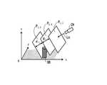
より具体的には、図1に模式例を示すように、例えばあるカメラCAから見て、xyz座標系で示されている世界座標系においてxy平面上に2つの対象(オブジェクト)(例えば、フィールド上のスポーツ選手といったような2人の人物等が想定されるが、ここでは模式例として2つの「円柱」で例示している)が前後に並んでおり一方(灰色の円柱CLB)がもう一方(白色の円柱CLF)によって遮蔽されているシーンを考える(このような対象同士のカメラ画像内の遮蔽を、以後オクルージョンと呼ぶ)。なお、図示するようにカメラCA(及び仮想視点に対応するカメラCV)から見ると+x方向が手前側、-x方向が後方側となる。この場合、カメラCAで撮影された画像(テクスチャ)PAは、手前側の遮蔽されていない対象(白色の円柱CLF)に貼り付けられる(マッピングされる)べきであり、オクルージョンによって見えない後方の対象(灰色の円柱CLB)にはマッピングされるべきではない。しかしながら、前述の通り特許文献1においては、(計算の高速化を実現するために)被写体の前後関係を計算していないため、オクルージョンの有無にかかわらずカメラ画像をすべての被写体に貼り付けてしまうことから、不自然な合成映像となる場合があった。 More specifically, as shown in a schematic example in FIG. 1, for example, when viewed from a certain camera CA, two objects (objects) (for example, fields) on the xy plane in the world coordinate system shown in the xyz coordinate system. Two people such as the above athlete are assumed, but here, as a schematic example, two "cylinders") are lined up in front and behind, and one (gray cylinder CLB) is the other. Consider a scene that is shielded by (white cylinder CLF) (such shielding in the camera image between objects is hereinafter referred to as occlusion). As shown in the figure, when viewed from the camera CA (and the camera CV corresponding to the virtual viewpoint), the + x direction is the front side and the -x direction is the rear side. In this case, the image (texture) PA taken by the camera CA should be pasted (mapped) to the unobstructed object (white cylinder CLF) on the front side and the rear object invisible by occlusion. Should not be mapped to (gray cylinder CLB). However, as described above, in
すなわち、合成映像を得るために用いる仮想視点が図1にてカメラCV(従って、カメラCVは実写映像を得るためのものではない)のような位置にあったとするとき、仮想視点に対応するカメラCVにおける合成映像は、当該位置に実際のカメラがあったとする場合に得られるべきものとして、画像PVのように後方の対象である灰色の円柱CLBのみが撮影された状態となっており、当該灰色の円柱CLBが白色の円柱CLFで遮蔽された状態ではないことが望まれるものである。しかしながら、当該合成映像を生成するための実写映像としてカメラCAの画像を用いたとすると、画像PAのように手前の白色の円柱CLFによって灰色の円柱CLBに対してオクルージョンが生じた状態(を仮想視点PVから見ていることに相当する状態)の画像PVAが合成され、本来合成されるべき画像PVが合成されないということがあった。 That is, when the virtual viewpoint used to obtain the composite image is in a position like the camera CV (therefore, the camera CV is not for obtaining the live-action image) in FIG. 1, the camera corresponding to the virtual viewpoint is used. The composite image in the CV is in a state where only the gray cylinder CLB, which is the object behind, is taken as the image PV, as it should be obtained when the actual camera is at the position. It is hoped that the gray cylinder CLB is not shielded by the white cylinder CLF. However, if the image of the camera CA is used as the live-action image for generating the composite image, the white cylinder CLF in the foreground causes occlusion with respect to the gray cylinder CLB as in the image PA (a virtual viewpoint). In some cases, the image PVA in the state (corresponding to the state seen from the PV) was synthesized, and the image PV that should be synthesized was not synthesized.
本発明は上記従来技術の課題に鑑み、特許文献1の枠組みに即した高速な処理によりオクルージョン問題にも対処することが可能な合成装置、方法及びプログラムを提供することを目的とする。 In view of the above problems of the prior art, an object of the present invention is to provide a synthesizer, a method and a program capable of dealing with an occlusion problem by high-speed processing in accordance with the framework of
上記目的を達成するため、本発明は合成装置であって、多視点画像の各視点画像から撮影されている対象の領域の尤度画像を求める算出部と、前記尤度画像の各々を3次元空間内に配置された複数の逆投影平面へと逆投影した逆投影データを得る逆投影部と、前記逆投影データに対して前記多視点画像の全部又は一部の視点画像のテクスチャを、当該逆投影データを構成する前記複数の逆投影平面へと順番に逆投影して描画して前記対象をレンダリングすることで、前記対象の自由視点画像を合成する描画部と、を備えることを特徴とする。また、当該装置に対応する方法及びプログラムであることを特徴とする。 In order to achieve the above object, the present invention is a synthesizer, and a calculation unit for obtaining a likelihood image of a target region captured from each viewpoint image of a multi-viewpoint image and each of the likelihood images are three-dimensional. A back-projection unit that obtains back-projection data back-projected onto a plurality of back-projection planes arranged in space, and the texture of all or part of the viewpoint image of the multi-viewpoint image with respect to the back-projection data. It is characterized by including a drawing unit that synthesizes a free-viewpoint image of the target by sequentially back-projecting and drawing on the plurality of back-projection planes constituting the back-projection data and rendering the target. To do. Further, it is characterized in that it is a method and a program corresponding to the device.
本発明によれば、多視点画像の全部又は一部の視点画像のテクスチャを逆投影平面へと順番に逆投影して描画することにより、高速な処理によりオクルージョンに対処して自由視点画像を合成することが可能となる。 According to the present invention, the textures of all or a part of the viewpoint images of the multi-view image are back-projected and drawn on the back-projection plane in order, so that the free-view image is synthesized by coping with occlusion by high-speed processing. It becomes possible to do.
図2は、一実施形態に係る合成装置の機能ブロック図である。図示する通り、合成装置10は、校正部1、抽出部2、算出部3、面群設定部4、順設定部5、逆投影部6、描画部7、再投影部8及び付与部9を備える。図示する通り、このうち逆投影部6、描画部7、再投影部8及び付与部9はレンダリング部20を構成している。合成装置10はその全体的な動作として、多視点映像としての複数のカメラ映像Vc,t(u,v)を入力として受け取り、当該カメラ映像Vc,t(u,v)に対してユーザ入力等によって指定される仮想視点CV(すなわち、自由視点CV)における合成映像SYt(u,v)を出力する。FIG. 2 is a functional block diagram of the synthesizer according to the embodiment. As shown in the figure, the synthesizer 10 includes a
なお、特許文献1に示される構成に対する主要な追加構成(ないし追加処理を行う構成)として、図2の合成装置10は順設定部5、描画部7、再投影部8及び付与部9を備えるものである。当該追加構成の機能部による追加処理と、当該追加処理に連携したその他の各機能部での処理と、のそれぞれが、本発明においてオクルージョンに配慮した合成映像SYt(u,v)を得ることを可能にするのに寄与している。As a main additional configuration (or configuration for performing additional processing) to the configuration shown in
ここで、本発明の説明に用いる映像データ等に関する表記の説明を行う。入力される多視点映像「Vc,t(u,v)」とは、複数N台のカメラc(c=1,2,…,N)の時刻t(t=1,2,3,…)の画素位置(u,v)(u,vは整数)における画素値を表すものとして、当該映像Vを変数(且つインデクス)c,t,u,vの関数として表記するものである。同様に、出力される合成映像「SYt(u,v)」も、当該時刻tの画素位置(u,v)における画素値を表すものとして、当該合成映像SYを関数として表記するものである。以下の説明に現れる各データもこれと同様に、大文字部分がデータ関数名を表し、これに続く下付き小文字部分がカメラc、時刻t、仮想平面k(後述)を区別するインデクスであり、さらにこれに続く(u,v)や(i,j)が位置を区別するインデクスである。当該インデクスのうちの一部が存在しない場合もある。Here, notations relating to video data and the like used in the description of the present invention will be described. The input multi-viewpoint video "Vc, t (u, v)" is the time t (t = 1,2,3, ...) of multiple N cameras c (c = 1,2, ..., N). ) At the pixel position (u, v) (u, v is an integer), the video V is expressed as a function of variables (and indexes) c, t, u, v. Similarly, the output composite video "SYt (u, v)" also represents the composite video SY as a function as representing the pixel value at the pixel position (u, v) at the time t. .. Similarly, in each data appearing in the following explanation, the uppercase part represents the data function name, the subscript lowercase part following this is the index that distinguishes the camera c, the time t, and the virtual plane k (described later), and further. Subsequent (u, v) and (i, j) are the indexes that distinguish the positions. Some of the indexes may not exist.
合成装置10は映像上の各時刻t=1,2,3,…の多視点映像Vc,t(u,v)(時刻tを固定した場合は多視点画像Vc,t(u,v))につき合成処理を行うことで合成映像SYt(u,v)(時刻tを固定した場合は合成画像SYt(u,v))を出力するが、当該合成処理は任意の時刻tについて共通である。従って、以下の説明においてはこのような入力映像Vc,t(u,v)における任意の時刻tにおける処理であるものとして、場合によっては特に時刻tに言及することなく、説明を行う。図1の合成装置10の各部の処理の概要は以下の通りである。The synthesizer 10 is a multi-view video V c, t (u, v) at each time t = 1,2,3, ... on the video (when the time t is fixed, the multi-view image Vc, t (u, v) )) per composite video SYt (u by performing the synthesis process, v) (time if t was fixed composite image SYt (u, v)) for outputting a while, the synthesizing process for any time t It is common. Therefore, in the following description, it is assumed thatthe processing is performed at an arbitrary time t in such an input video V c, t (u, v), and in some cases, the time t will not be particularly mentioned. The outline of the processing of each part of the synthesizer 10 of FIG. 1 is as follows.
まず、合成装置10への入力としての多視点画像Vc,t(u,v)は、校正部1、抽出部2及び描画部7へと入力される。ここで、当該入力される多視点画像Vc,t(u,v)の各カメラcにおける画像には、異なるカメラ画像間での時刻同期が行われたうえで、(すなわち、時刻tは異なるカメラ画像間で当該同期された共通時刻であるものとして、)同一の対象が当該カメラcの撮影位置から撮影されているものとする。First, the multi-viewpoint images V c, t (u, v) as inputs to the synthesizer 10 are input to the
<校正部1>
校正部1は、いわゆるカメラ校正を行うものであり、多視点画像(における各カメラcの画像)Vc,t(u,v)を入力として、カメラcごとに実空間の地面(フィールド)の座標(x,y,z)とカメラ画像Vc,t(u,v)との対応付けを取り、得られたキャリブレーション(校正)データ(すなわち、カメラパラメータ)のうちの外部パラメータを逆投影部6及び描画部7へと出力する。当該各部2,6,7は当該得られた校正データを用いることでそれぞれの処理が可能となる。(なお、周知のように、キャリブレーションではレンズ歪を解消する内部パラメータも得ることができるが、合成装置10の各部では当該内部パラメータを用いた歪補正済みのデータを利用してよい。内部パラメータに関するデータ授受の流れは図2では省略している。)<
The
なお、校正部1による当該キャリブレーション操作は固定カメラを前提とした場合であれば、各カメラcにおいてある時刻tに一度操作を行うのみよく、その後の時刻t+1,t+2,…においては既に時刻tで得られている校正データを利用するようにすればよい。また、多視点画像Vc,t(u,v)に既に校正データが紐づけて与えられている場合には、校正部1は省略されてもよい。(この場合は、校正部1が合成装置10の外部構成として存在しているものとみなすことができる。)If the calibration operation by the
図3に、当該カメラ校正によりカメラcの画像Vc,t(u,v)の座標(u,v)cと世界座標系の点(x,y,z)との対応付けが可能となることの模式例を示す。カメラcのカメラ中心と座標(u,v)cとを通る直線L(u,v)上に点(x,y,z)が存在するという形で当該対応付けが可能となっている。なお、当該カメラ校正による世界座標系(x,y,z)は全てのカメラcにおいて共通のものである。3, the image Vc of the camerac, t (u, v) coordinates (u, v) ofc and the world coordinate system a point (x, y, z) is correspondence between made possible by the camera calibration A schematic example of this is shown. The association is possible in the form that a point (x, y, z) exists on a straight line L (u, v) passing through the camera center of the camera c and the coordinates (u, v)c. The world coordinate system (x, y, z) obtained by the camera calibration is common to all cameras c.
校正部1におけるカメラ校正に関しては、任意の既存手法を用いてよく、自動及び/又は人手により、例えば特徴点や線分を検出可能なマーカを世界座標(x,y,z)の既知の位置に配置したうえで、カメラcの座標(u,v)cにおける特徴点座標や線分関連座標との対応関係を求め、カメラパラメータを取得するようにするようにすればよい。For camera calibration in the
<抽出部2>
抽出部2では、各カメラcの画像Vc,t(u,v)に対して、既存手法である背景差分法を用いて画像内の背景と前景を分類し、当該分類を表現する2値又は前景の尤度(グレースケール階調等で与えればよい)を画素値とするマスク画像Mc,t(u,v)を得て、算出部3へと出力する。ここで、当該分類される前景は画像Vc,t(u,v)において撮影されている対象(例えば、人物等)の領域となる。<
図4は、抽出部2での抽出処理の模式例を示す図であり、対象(オブジェクト)としての人物を含むある時刻tの原画像[1]に対し、背景差分法を適用することによって、背景差分結果としての画像[2]が生成されている。この画像[2]は、対象である人物に相当する前景画素部分が白色(画素値が1)であってその他の背景画素部分は黒色(画素値が0)であるマスク画像となっている。 FIG. 4 is a diagram showing a schematic example of the extraction process in the
なお、図4では、このマスク画像[2]と原画像[1]とから、人物(対象)のテクスチャ情報を含み背景画素部分は黒色のままであるオブジェクトのテクスチャ画像[3]も取得可能となることが示されている。このように、画像背景とその前景との分離を行うことによって、人物等の対象(の画像情報)を大まかに抽出することが可能となる。 In addition, in FIG. 4, from the mask image [2] and the original image [1], it is possible to obtain the texture image [3] of the object including the texture information of the person (target) and the background pixel portion remains black. It has been shown to be. By separating the image background and the foreground in this way, it is possible to roughly extract the object (image information) of a person or the like.
ここで、抽出部2において背景差分法を適用するに際しては、各カメラcの画像Vc,t(u,v)についての背景画像BGc,t(u,v)を予め与えておくものとする。なお、カメラcが固定されており光源条件などが不変であるならば、背景画像は静止画でよい。また、抽出部2においてマスク画像Mc,t(u,v)を2値マップ(前景/背景の区別のみ)ではなく前景に関する尤度マップとして求める場合は、任意種類の既存の対象(物体など)尤度の算出手法を用いてよく、例えば顕著性(Saliency)マップ等として求めるようにすればよい。Here, when applying the background subtraction method in the
なお、抽出部2に関しても前述の校正部1と同様に、入力される画像Vc,t(u,v)に予めマスク画像Mc,t(u,v)が紐づけられているのであれば、抽出部2は合成装置10から省略された外部構成としてもよい。As for the extraction unit 2, the mask image M c, t (u, v) is associatedwith the input image V c, t (u, v) in advance, as in the
<算出部3>
算出部3は、抽出部2で生成されたマスク画像Mc,t(u,v)を用い、後段側に位置している機能部(この後の処理を担う機能部)である逆投影部6によって逆投影面群に逆投影するために用いるアルファ値α1c,t(u,v)を、各視点画像としてのカメラ画像c毎に算出し、当該アルファ値α1c,t(u,v)を逆投影部6へと出力する。なお、当該算出されるアルファ値は、後段側の描画部7において最終的に合成される自由視点画像SYt(u,v)におけるオブジェクトの輪郭の残り具合を加減するパラメータとしての役割を果たすこととなる。算出部3では具体的に以下の各実施形態でアルファ値α1c,t(u,v)を算出することができる。<
The
第一実施形態では、最も簡素な算出手法として、抽出部2から得られたマスク画像Mc,t(u,v)の画素値をそのままアルファ値として採用する。例えば、マスク画像Mc,t(u,v)が2値(0又は1)のものとして抽出されている場合であれば、その画素値をそのまま2値のアルファ値としてもよい。すなわち、前景(画素値=1)領域のアルファ値が1となり、背景(画素値=0)領域のアルファ値が0となる。また、マスク画像Mc,t(u,v)が前景の尤度マップとして与えられていれば、当該尤度マップをそのままで、あるいは、値が0以上1以下となるように規格化したものとして、アルファ値を得るようにすればよい。In the first embodiment, as the simplest calculation method,the pixel values of the mask images M c, t (u, v) obtained from the
なお、第一実施形態は、算出部3が合成装置10から省略されている構成(算出部3で得たマスク画像Mc,t(u,v)がアルファ値α1c,t(u,v)であるものとして直接に逆投影部6へと入力される構成)とみなすこともできる。(尤度マップに関して規格化する場合は当該規格化を抽出部2の段階で実施しておけばよい。)In the first embodiment, the
第一実施形態は、抽出部2において、前景被写体のマスク画像Mc,t(u,v)が正しく抽出されている場合には有効となる。しかしながら、実際には、現実世界の映像からマスク画像を抽出した際、ノイズの影響により、例えば被写体の一部が欠損しているようなマスク画像(2値の場合)が抽出されることも少なくない。このように、正しいマスク画像の抽出が期待され得ない状況にも好適な別の実施形態として、以下の第二及び第三実施形態がある。The first embodiment is effective when the mask image Mc, t (u, v) of the foreground subject is correctly extracted in the
なお、第二及び第三実施形態ではマスク画像Mc,t(u,v)の前景と背景とが2値的に区別されることを前提とする。マスク画像Mc,t(u,v)が前景の尤度としてグレースケール階調等の2値よりも多い段階値(又は連続値)で与えられている場合には、当該尤度に対して閾値判定から前景又は背景の区別を得るようにすればよい。In the second and third embodiments, it is premised that the foreground and the backgroundof the mask image M c, t (u, v) are binaryally distinguished. When the mask image Mc, t (u, v) is given as the likelihood of the foreground with a step value (or continuous value) more than two values such as grayscale gradation, the likelihood is relative to the likelihood. The foreground or background may be distinguished from the threshold value determination.
第二実施形態では、マスク画像Mc,t(u,v)における前景の画素は第一実施形態と同様の値(アルファ値が1)を採用するが、背景の画素についてはそのアルファ値を、非ゼロであってゼロより大きく1未満の値τ(0<τ<1、例えばτ=0.5)に設定することにより、アルファ値α1c,t(u,v)を算出する。In the second embodiment,the foreground pixels in the mask image M c, t (u, v) adopt the same value (alpha value is 1) as in the first embodiment, but the alpha value is used for the background pixels., The alpha value α1 c, t (u, v) is calculated by setting the value τ (0 <τ <1, for example τ = 0.5) which is non-zero and is greater than zero and less than 1.
第二実施形態によれば、次いで実施される逆投影部6における処理で逆投影を行ってアルファ値α1c,t(u,v)を重ね合わせた際、背景画素値τがゼロではないので、前景と背景との境界部分が若干残りやすくなる効果が期待され、抽出部2で抽出されたマスク画像Mc,t(u,v)の不正確さによる悪影響を低減する方向へと処理を進めることが可能となる。According to the second embodiment, the background pixel value τ is not zero when theback projection is performed and the alpha values α1 c, t (u, v) are superimposed in the processing in the back projection unit 6 to be performed next. , The effect that the boundary part between the foreground and the background is likely to remain is expected, and the processing is performed in the direction of reducing the adverse effect due to the inaccuracy ofthe mask image M c, t (u, v) extracted by the extraction unit 2. It will be possible to proceed.
第三実施形態は、上記の第二実施形態で背景アルファ値τがその位置によらず固定値とされていたのを位置に応じて変化させるものであり、マスク画像Mc,t(u,v)における前景と背景との境界からアルファ値を決定する対象となる画素までの距離が大きくなるに従い、当該背景画素に設定されるアルファ値が減少していくものとして、アルファ値α1c,t(u,v)を算出する。具体的には、アルファ値を決定する対象の背景画素から、当該画素近傍のマスク境界までの距離(例えば垂線距離)をdとして、アルファ値αを、例えば次式
(1) α=θ・f(d)
を用いて算出することができる。ここで、f(d)はアルファ値を返すdの単調減少関数であり、θはアルファ値の減衰率である。In the third embodiment, the background alpha value τ is fixed regardless of the position in the second embodiment described above, but is changed according to the position, and the mask image Mc, t (u, Assuming that the alpha value set for the background pixel decreases as the distance from the boundary between the foreground and the background in v) to the pixel for which the alpha value is determined increases, the alpha value α1c, t Calculate (u, v). Specifically, the alpha value α is set to, for example, the following equation (1) α = θ · f, where d is the distance from the background pixel for which the alpha value is determined to the mask boundary in the vicinity of the pixel (for example, the perpendicular distance). (d)
Can be calculated using. Here, f (d) is a monotonic decrease function of d that returns an alpha value, and θ is the attenuation factor of the alpha value.
第三実施形態は、第二実施形態と比較すると、より自然な見た目をもって被写体(対象)を自由視点映像化することを可能にするが、一方で、各画素近傍のマスク境界までの距離dを算出する必要があるので、計算量及び計算時間が増大する方向にあるといえる。 The third embodiment makes it possible to visualize the subject (object) from a free viewpoint with a more natural appearance as compared with the second embodiment, but on the other hand, the distance d to the mask boundary near each pixel is set. Since it is necessary to calculate, it can be said that the amount of calculation and the calculation time are increasing.
さらに、以上に述べた各実施形態以外でも、例えば前景の画素のアルファ値を1とし、一方で背景の画素のアルファ値を1未満の値とするような算出方法であれば、種々の方法が採用可能である。 Further, other than the above-described embodiments, various methods are available as long as the calculation method is such that, for example, the alpha value of the foreground pixel is 1 and the alpha value of the background pixel is less than 1. It can be adopted.
<面群設定部4>
面群設定部4は、多視点画像Vc,t(u,v)の世界座標系xyzをモデル化した3次元モデル空間内に、後段側処理部の逆投影部6等で用いる投影先としての複数の面である逆投影面群Pを設定して、順設定部5へと当該設定結果(すなわち、面群Pを構成する各面が3次元モデル空間内において占める座標位置・範囲)を出力する。詳細を後述する通り、この逆投影面群Pは、入力された多視点画像Vc,t(u,v)を3次元モデル空間へ逆投影する際の基準として用いられるものである。<Surface
The surface
面群設定部4では具体的に、ユーザ入力等によって指定される3次元モデル空間内の仮想視点CVの位置(及び視線の向き)に応じたものとして、逆投影面群Pを設定することができる。図5は、当該設定する一実施形態を説明するための模式例を示す図である。(図5はまた、後述する順設定部5の一実施形態の模式例ともなっている。)一実施形態では、ユーザ入力等により指定される3次元モデル空間内での仮想視点CVの位置及びその視線方向Lc(すなわち、仮想視点CVのカメラ軸Lc)に対し、当該カメラ軸Lcの直線を貫くそれぞれ所定サイズのK個の平面からなる平面群P={Pt,k|k=1,2,…,K}であって、各平面Pt,kがカメラ軸Lcに対して所定角度をなして互いに平行なものとして設定することができる。In the surface
ここで、設定する各平面Pt,kの3次元モデル空間内での向きに関して、次のような各実施形態が可能である。すなわち、各平面Pt,kがカメラ軸Lcとなす角は任意の所定角でよいが、一実施形態では当該角度を直角としてよい。また、カメラ軸Lcを基準として各平面Pt,kの向きを設定するのではなく、3次元モデル空間内に設定されているxyz座標(世界座標系xyzと同一)を基準とした向きを設定するようにしてもよい。例えばxy平面が地面(フィールド)であるものとして、xy平面に平行な平面群Pを設定してもよいし、あるいは、yz平面又はzx平面に平行な平面群Pを設定してもよい。Here, withrespect to the orientation of each plane P t, k to be set in the three-dimensional model space, the following embodiments are possible. That is, theangle formed by each plane P t, k with the camera axis Lc may be any predetermined angle, but in one embodiment, the angle may be a right angle.Also, instead of setting the orientation of each plane P t, k with respect to the camera axis Lc, set the orientation with reference to the xyz coordinates (same as the world coordinate system xyz) set in the 3D model space. You may try to do it. For example, assuming that the xy plane is the ground (field), a plane group P parallel to the xy plane may be set, or a plane group P parallel to the yz plane or the zx plane may be set.
なお、校正部1に関して図3等を参照して説明した世界座標系xyz(すなわち、多視点画像Vc,t(u,v)が撮影された空間としての世界座標系xyz)を、合成画像SYt(u,v)を得るレンダリングのためにモデル化したものが3次元モデル空間である。ここで、世界座標系xyzの各点の位置と3次元モデル空間の各点の位置は一対一に対応しているので、3次元モデル空間に関してもその座標系を世界座標系と同じ「xyz」であるものとして、以下でも説明を行うものとする。A composite image of the world coordinate system xyz (that is, the world coordinate system xyz as the space in which themulti-viewpoint images V c, t (u, v) were captured) described with reference to FIG. 3 and the like with respect to the
また、一実施形態では、互いに平行な平面Pt,k同士は隣接するもの同士が所定距離dをもって離れて位置しているものとして平面群Pを設定すればよい。別の一実施形態では、平面Pt,kのうち隣接するものの間の距離は一定値dではなく、変化するものであってもよい。例えば、3次元モデル空間において対象の存在する可能性の高い位置の近くに存在する平面Pt,kほど当該距離を小さくする等の設定を用いてもよい。Further, in one embodiment, theplane group P may be set assuming that the planes P t and k parallel to each other are located apart from each other with a predetermined distance d. In another embodiment,the distance between adjacent planes P t, k may be variable rather than constant value d. For example, a setting may be used such that the distance is made smaller as theplane P t, k exists near the position where the object is likely to exist in the three-dimensional model space.
なお、本発明において面群設定部4で設定する平面群Pは、従来技術の視体積交差法における3次元ボクセル(点群)が果たす役割を、深さ情報を不要として2次元領域(としての当該平面群P)において実現することで、メモリ消費を抑制して高速に自由視点の合成映像SYt(u,v)の合成を可能とするものである。従って、3次元モデル空間xyz内において平面群Pが配置される範囲は、多視点画像Vc,t(u,v)から抽出部2でその被写体領域がマスクMc,t(u,v)として抽出される対象(最終的に描画部7にて自由視点でのレンダリングがなされる対象)が存在しうる範囲をカバーするものであればよい。当該存在しうる範囲の情報は多視点画像Vc,t(u,v)に紐づいた情報として予め与えておき、面群設定部4では当該範囲をカバーするように、平面群Pを設定すればよい。(当該紐づいた情報はさらに、校正部1の校正情報に関連付けられて予め与えられていてもよい。)すなわち、平面群Pに関して、構成される平面の個数K、面間の距離d、各面の大きさなどのメモリ消費に関連する設定を、当該範囲をカバーするように設定すればよい。In the present invention, the plane group P set by the surface
なお、仮想視点CVの視点位置(及び向き)をユーザ等が指定する場合は、任意の既存の情報入力インタフェースを利用してよい。例えば、数値として直接入力してもよいし、当該数値を既存の視線位置検出技術(瞳撮影用のカメラに対するユーザの瞳の位置の検出)から求めるようにしてもよい。当該数値をマウス操作やタッチパネル上の操作から算出して取得してもよい。複数の視点位置の候補からメニュー選択で入力するようにしてもよい。 When the user or the like specifies the viewpoint position (and orientation) of the virtual viewpoint CV, any existing information input interface may be used. For example, it may be directly input as a numerical value, or the numerical value may be obtained from an existing line-of-sight position detection technique (detection of the position of the user's pupil with respect to a camera for pupil photography). The numerical value may be calculated and acquired from a mouse operation or an operation on the touch panel. It is also possible to input by menu selection from a plurality of viewpoint position candidates.
<順設定部5>
順設定部5は、面群設定部4で以上のように設定した面群Pを構成する各平面Pt,kに対して順番を設定して、当該順番設定された面群P={Pt,k|k=1,2,…,K}を描画部7へと出力する。後述する描画部7では当該出力された順番に従って面群Pを用いた処理を行う。<
The order setting unit 5 sets the order for each plane P t, k constituting the surface group P set as described above in the surface
順設定部5では具体的に、面群設定部4が設定した面群P={Pt,k|k=1,2,…,K}に関して、面群設定部4においてユーザ入力等によって指定された仮想視点CVの位置との関係に基づいた順番を設定することができる。好適な一実施形態として、仮想視点CVから各面が近い順で順番を付与してもよい。なお、以下では面群P={Pt,k|k=1,2,…,K}等の表記を用いた場合、各面を区別するインデクスkは、順設定部5で当該付与された順番を表しているものとする。また、説明例として、当該近い順番kを設定した場合を説明する。すなわち、面群Pにおける平面Pt,kとは、仮想視点CVからの距離の近さがk番目である平面を表すものとし、kが小さいほど仮想視点CVに対して手前に位置しており、kが大きいほど仮想視点CVから見て奥側に位置しているものとする。Specifically, in the
例えば、図5の模式例は指定された仮想視点CVに対してカメラ軸方向Lcに垂直な面群P(模式例として、K=3個の平面で構成される面群P)を面群設定部4において設定し、さらに、順設定部5において仮想視点CVから位置が近い順にk=1,2,3と順番を設定することで、面群Pとして当該近い順の3個の平面Pt,1,Pt,2,Pt,3が3次元モデル空間xyz内に、互いに距離dだけ離れて設定される例となっている。また、当該設定された3個の平面Pt,1,Pt,2,Pt,3は対象OBの存在しうる範囲をカバーしているものとなっている。For example, in the schematic example of FIG. 5, a surface group P perpendicular to the camera axis direction Lc with respect to the specified virtual viewpoint CV (as a model example, a surface group P composed of K = 3 planes) is set as a surface group. By setting in the
<レンダリング部20>
レンダリング部20は、校正部1で得たキャリブレーションデータと、算出部3で算出されたアルファ値α1c,t(u,v)と、順設定部5で設定された順序付与された面群P={Pt,k|k=1,2,…,K}と、を用いることにより、合成装置10への入力としての多視点画像Vc,t(u,v)における対象を自由視点化してディスプレイ領域にレンダリングした結果として、合成画像SYt(u,v)を得る。<Rendering section 20>
The rendering unit 20 includes the calibration data obtained by the
より具体的に、レンダリング部20はハードウェアとしては例えばGPUを用いて実現することが可能であり、順序付与して設定された面群P={Pt,k|k=1,2,…,K}をGPUの頂点シェーダへ当該順序kにて入力し、面群設定部4においてユーザ等から指定された仮想視点CVの情報(視点位置座標及び視線向き情報)に基づいて、ディスプレイ上に当該仮想視点CVにおけるものとしての対象の自由視点画像をレンダリングし、合成画像SYt(u,v)を得る。(GPUのピクセルシェーダによってピクセル単位でレンダリングするようにしてもよい。)ここでこの際、対象以外の背景の情報である3DCGデータも読み込み、公知の方法に基づき同時に並行してレンダリングを行うことによって、最終的な自由視点画像を合成することができる。なお、背景の情報としての3DCGデータは、抽出部2で背景差分法を適用する際に用意しておく所定背景を仮想視点CVで見たものへと変換(平面部分ごとの平面射影変換等)することで合成されるものであってもよい。More specifically, the rendering unit 20 can be realized by using, for example, a GPU as hardware, and the surface group P = {Pt, k | k = 1,2, ... , K} is input to the GPU vertex shader in the order k, and based on the virtual viewpoint CV information (viewpoint position coordinates and line-of-sight direction information) specified by the user etc. in the surface
以下、レンダリング部20における当該レンダリング処理を実現するための要素処理を担う逆投影部6、描画部7、再投影部8及び付与部9に関して説明する。ここで、各部6,7,8,9の個別処理を説明した後に、描画部7以降の各部7,8,9についてはさらに、互いに連携しての繰り返し処理・更新処理を伴うものであるため、後述の図7を参照してその動作フローを説明する。 Hereinafter, the back projection unit 6, the
<逆投影部6>
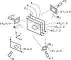
図6は逆投影部6の処理を、カメラが3個(c=1,2,3)及び面群Pが3個の面(k=1,2,3)で構成される場合に関して、模式的に示すものである。逆投影部6は、算出部3から得た各カメラc(c=1,2,…,N)に関するアルファ値α1c,t(u,v)を、順設定部5で得た面群P={Pt,k|k=1,2,…,K}の各々の面Pt,k上に逆投影したうえで積算することにより、各面Pt,k上における積算されたアルファ値α2t,k(i,j)を得る。<Back projection 6>
FIG. 6 illustrates the processing of the back projection unit 6 with respect to the case where the camera is composed of three faces (c = 1,2,3) and the face group P is composed of three faces (k = 1,2,3). It is shown as a target.The back projection unit 6 obtains the alpha values α1 c, t (u, v) for each camera c (c = 1,2, ..., N) obtained from the
ここで、各データ内容の区別の明確化のために、次のように区別した表記を用いている。すなわち、算出部3で得られるアルファ値を「α1」、逆投影部6でこれらを各カメラcについて積算して得られるアルファ値を「α2」として名前(関数表記の名前)を区別している。また、算出部3のアルファ値α1は入力画像Vc,t(u,v)の位置(u,v)に対応するので画素位置(u,v)として表記し、一方、逆投影部6のアルファ値α2はxyz空間内に配置された各面Pt,k上における分布として与えられるものであるため、(u,v)とは区別してその平面上の位置を(i,j)としている。なお、当該位置(i,j)は画素位置(u,v)とは異なり、一般に実数で指定されるものとなる。Here, in order to clarify the distinction between each data content, the following notation is used. That is, the alpha value obtained by the
図6にも模式的に示されているが、逆投影部6ではインデクスkで指定される各逆投影面Pt,kに対して、以下の手順1〜3で当該面Pt,k上における積算されたアルファ値α2t,k(i,j)を得ることができる。なお、(後述する描画部7とは異なり、)逆投影部8では各逆投影面Pt,kに関して、(インデクスkで指定される順番に限らず、)任意の順番で以下の手順1〜3を実施してよい。また、複数の平面Pt,kに関して並行で実施してもよい。Although shown schematically in Figure 6, the back projection plane Pt specified by the inverse projection unit 6 indexk, with respect tok, the face Pt by the following
(手順1)アルファ値画像α1c,t(u,v)を、当該画像を得たカメラcの3次元モデル空間xyz内での配置位置に対応する位置に配置する。(Procedure 1) The alpha value image α1c, t (u, v) is placed at a position corresponding to the placement position in the three-dimensional model space xyz of the camera c that obtained the image.
(手順2)3次元モデル空間xyz内に上記配置したアルファ値画像α1c,t(u,v)を、対応するカメラcのカメラ中心から、面Pt,kへ向けて逆投影することで、アルファ値画像α1c,t(u,v)の各画素位置(u,v)の面Pt,k上における逆投影位置(i[u,v],j[u,v])cを得る。ここで、空間xyz内にて当該逆投影される範囲はカメラcのカメラ中心を頂点としアルファ値画像α1c,t(u,v)を底面(当該錐体の切断面、2値で底面領域が定義される場合を想定)とする錐体CNc,tで表現される。図6ではc=1,2,3に関して当該錐体CNc,tが破線によって模式的に示されている。面Pt,kへ向けての投影結果は積集合「Pt,k∩CNc,t」である。(Procedure 2) By back-projectingthe alpha value image α1 c, t (u, v) arranged above in the three-dimensional model space xyz from the camera center of the corresponding camera c toward the plane Pt, k. , Alpha value The back projection position (i[u, v] , j[u, v] )con the plane P t, k of each pixel position (u, v) of theimage α1 c, t (u, v). obtain. Here, the back-projected range in the space xyz has the camera center of the camera c as the apex and the alpha value image α1c, t (u, v) as the bottom surface (the cut surface of the cone, the bottom area with binary values). Is represented by the cones CNc and t. In FIG. 6, the cones CNc and t are schematically shown by broken lines with respect to c = 1,2,3. The projection result toward the plane Pt, kis the intersection "P t, k ∩ CNc, t ".
(手順3)上記得た逆投影位置(i[u,v],j[u,v])c(当該位置は、面Pt,kの配置によってxyz空間内の位置でもある)上において対応する各カメラc(c=1, 2,…, Nの全てのうち、当該逆投影が可能なもの)のアルファ値α1c,t(u,v)(すなわち、投影元のアルファ値α1c,t(u,v))を積算することにより、アルファ値α2t,k(i,j)を得る。こうして例えば、アルファ値α1c,t(u,v)が2値マスクである場合、すべてのカメラcにおいて1となっている箇所のα2t,k(i,j)は1(対象)となり、1つでも0が含まれれば0(対象の領域ではない)となる。また、算出部3にて0〜1の値を連続的にα1c,t(u,v)に設定した場合は、境界が徐々に0に近づく効果が得られる。(Procedure 3) Correspondence on the back projection position (i[u, v] , j[u, v] )c (the position is also the position in the xyz space depending on the arrangementof the planes P t and k) obtained above.Alpha value α1 c, t (u, v) of each camera c (all of c = 1, 2, ..., N that can be back-projected) (that is, the alpha value α1c of the projection source) By integrating t (u, v)), the alpha value α2t, k (i, j) is obtained. Thus, for example, if the alpha value α1c, t (u, v) is a binary mask, the α2t, k (i, j) where it is 1 in all cameras c becomes 1 (target). If even one 0 is included, it becomes 0 (not the target area). Further, when the value of 0 to 1 is continuously set to α1c, t (u, v) in the
<描画部7>
描画部7では、面群設定部4においてユーザ入力等で指定された仮想視点CVから見た自由視点画像として、合成画像SYt(u,v)を合成する。ここで、多視点画像Vc,t(u,v)に撮影されている対象を当該仮想視点CVから見た状態として前景テクスチャTXc,t(u,v)としてレンダリングすると共に、既に説明した通りの公知の手法で当該仮想視点CVから見た状態での背景BGt(u,v)を合成することにより、合成画像SYt(u,v)を得る。<
The drawing unit 7 synthesizes a composite image SY t (u, v) as a free viewpoint image viewed from a virtual viewpoint CV specified by user input or the like in the surface
ここで、描画部7では具体的に前景テクスチャTXc,t(u,v)を描画するに際して、順設定部5で得た面群P={Pt,k|k=1,2,…,K}の順番kに従って逆投影面Pt,kの順で描画を行う。当該描画の際に用いる多視点画像Vc,t(u,v)は、インデクスc=1,2,…,Nで区別される全カメラcのうち、指定された仮想視点CVに位置(及び向き)が近いと判定されたn個(n≦N)のものを用いる。なお、当該n個を用いることは、例えば仮想視点CVから逆向きのカメラcの画像Vc,t(u,v)は、対象を仮想視点CVとは反対側から見ているものに相当するため、描画に必要なテクスチャが含まれていない可能性が高いためである。Here, when the foreground texture TX c, t (u, v) is specifically drawn in the
例えば、各カメラcが対象を円周状に又は球面状に取り囲んで配置され対象の方を向いて撮影している場合であって、仮想視点CVも当該円周又は球面の近傍から対象の方を見るものとして設定される場合であれば、位置の近さと向きの近さとは連動するので、位置又は向きのいずれかの近いn個を選択すればよい。各カメラcの配置が任意の場合には、位置及び向きの両方を考慮して、仮想視点CVに近いと判定されるn個のカメラcを選択すればよい。 For example, when each camera c is arranged so as to surround the object in a circumferential shape or a spherical shape and is shooting toward the target, the virtual viewpoint CV is also the target person from the vicinity of the circumference or the spherical surface. If it is set to look at, the proximity of the position and the proximity of the orientation are linked, so it is sufficient to select n close to either the position or the orientation. If the arrangement of each camera c is arbitrary, n cameras c that are determined to be close to the virtual viewpoint CV may be selected in consideration of both the position and the orientation.
以下、説明のため、当該位置(及び向き)が近いと判定されたn個のカメラのインデクスがc=1,2,3,…,nであるものとする。 Hereinafter, for the sake of explanation, it is assumed that the indexes of the n cameras determined to be close to each other are c = 1,2,3, ..., N.
<再投影部8>
また、描画部7における逆投影面Pt,kに関する描画において、当該n個のカメラにおける多視点画像Vc,t(u,v)の中からそれぞれ、実際に当該描画に用いるための領域Sc,t,k(u,v)の設定を行うのが再投影部8である。再投影部8は領域Sc,t,k(u,v)を求めて描画部7及び付与部9へと出力する。<Reprojection unit 8>
Further, in the drawingrelated to the back projection planes P t and k in the
<付与部9>
また、描画部7が当該描画するために用いる領域Sc,t,k(u,v)(画像Vc,t(u,v)の一部に相当)の各画素位置(u,v)に関しては、順番kに従って逆投影面Pt,kの順で描画を行っていくに際して、既にテクスチャTXc,t(u,v)の描画に用いられたか否か等の描画履歴を反映した情報が制御値dc,t,k-1(u,v)として保持・更新されており、描画部7では当該制御値dc,t,k-1(u,v)を考慮して描画を行う。付与部9は、当該描画の際に考慮される制御値dc,t,k-1(u,v)を求め、描画部7へと出力するものである。<Granting part 9>
Further, each pixel position (u, v) of thearea Sc, t, k (u, v) (corresponding to a part of the image V c, t (u, v)) used by the
付与部9では、各画素位置(u,v)に関しては、順番kに従って逆投影面Pt,kの順で描画を行っていくに際しての描画履歴を反映したものとして、制御値dc,t,k-1(u,v)を求める。例えば、当該描画がなされた回数として制御値dc,t,k-1(u,v)として求めてよい。以下では制御値dc,t,k-1(u,v)は当該描画がなされた回数であるものとして説明する。In the addition unit 9, for each pixel position (u, v), the control values d c, t are assumed to reflect the drawing history when drawing in the order of theback projection planes P t, k according to the order k., k-1 (u, v) is calculated.For example, the control value d c, t, k-1 (u, v) may be obtained as the number of times the drawing is performed. In the following, the control values dc, t, k-1 (u, v) will be described assuming that the drawing is performed.
以上、描画部7、再投影部8及び付与部9の個別処理の概略を説明した。図7は、描画部7、再投影部8及び付与部9が互いに連携してテクスチャTXc,t(u,v)を描画する動作の一実施形態に係るフローチャートである。以下、図7の各ステップを説明しながら、各部7,8,9の動作の詳細を説明する。ここで、図7のフロー構造が繰り返し処理の構成を取ることが見て取れるが、当該繰り返し処理は順番k=1,2,…,Kに従って逆投影面Pt,kの順で描画することを表現したものである。従って、図7の説明においてはインデクスkを逆投影面Pt,kの識別子kとしての意味のほか、当該繰り返し処理の回数カウンタkの意味としても用いることとする。The outline of the individual processing of the
図7のフローを開始する際にはカウンタkを初期値k=1へと設定したうえで、ステップS1へと進む。 When starting the flow of FIG. 7, the counter k is set to the initial value k = 1, and then the process proceeds to step S1.
<ステップS1>
ステップS1では、付与部9が制御値dc,t,k-1(u,v)の初期値「k=1」における初期値dc,t,0(u,v)を、描画に用いる対象となっている各カメラc=1,2,…,nの画像Vc,t(u,v)の各画素位置(u,v)に対応するものとして設定してから、ステップS2へと進む。(なお、「初期値dc,t,0(u,v)」との記載に関して、「k=0」の逆投影面Pt,kは存在しないが、以下に説明するように「制御値dc,t,k-1(u,v)」(k≧1)は逆投影面Pt,k(k≧1)に対する描画の際に利用する制御値であるので、初回k=1の逆投影面Pt,1で利用する制御値として「初期値dc,t,0(u,v)」が存在する。)<Step S1>
In step S1, the assigning unit 9 uses theinitial values d c, t, 0 (u, v) at the initial value “k = 1” of thecontrol values d c, t, k-1 (u, v) for drawing. Set as corresponding to each pixel position (u, v) ofthe image V c, t (u, v) of each target camera c = 1,2, ..., n, and then proceed to step S2. move on. (In addition,regarding the description of "initial value d c, t, 0 (u, v)", the back projection plane Pt, k of "k = 0" does not exist, but as explained below, "control value". dc, t, k-1 (u, v) ”(k ≧ 1) isa control value used when drawing on the back projection plane P t, k (k ≧ 1), so the first k = 1There is an "initial value d c, t, 0 (u, v)" as a control value used on the back projection plane Pt, 1.)
ここで、ステップS1の時点ではまだ描画がなされていないので、付与部9では初期値dc,t,0(u,v)の値を全てのカメラc=1,2,…,n及び画素位置(u,v)に関して0(描画回数ゼロ)として付与すればよい。Here, since drawing has not been performed yet at the time of step S1, in the addition unit 9, the initial values dc, t, 0 (u, v) are set to all cameras c = 1,2, ..., n and pixels. It may be given as 0 (zero drawing count) for the position (u, v).
<ステップS2>
ステップS2では、再投影部8が、描画対象の各カメラc=1,2,…,nにおける画像Vc,t(u,v)内の部分領域として、再投影領域Sc,t,k(u,v)を設定してからステップS3へと進む。<Step S2>
In step S2, the reprojection unit 8 sets the reprojection area S c, t, kas a partial area in the image V c, t (u, v) at each camera c = 1,2, ..., N to be drawn. After setting (u, v), proceed to step S3.
図8は、再投影部8が再投影領域Sc,t,k(u,v)を得る処理の模式例を示す図である。図8にて、[1]から[2]へと矢印線L1で示される処理は既に図6等も参照して説明した逆投影部6による逆投影処理を示すものであり、逆投影平面Pt,k上に逆投影されたアルファ値α2t,k(i,j)が楕円状の領域として示されている。図8ではこれに次いで[2]から[3]へと矢印線L2で示されるのが再投影部8による処理の模式例となっている。FIG. 8 is a diagram showing a schematic example of a process in which thereprojection unit 8 obtains the reprojection region Sc, t, k (u, v). In FIG. 8, the process indicated by the arrow line L1 from [1] to [2] indicates the back projection process by the back projection unit 6 already described with reference to FIG. 6 and the like, and the back projection plane P.Thealpha value α2 t, k (i, j) back-projected on t, k is shown as an elliptical region. In FIG. 8, the arrow line L2 from [2] to [3] is shown as a schematic example of the processing by the reprojection unit 8.
ここで、再投影部8の処理及びその意義を説明するに際して、用語を次のように定義する。図6の模式例等においても既に説明の通り、逆投影部6で得る逆投影されたアルファ値α2t,k(i,j)を全ての逆投影面Pt,k上に分布した状態として空間xyz内に並べたもの{α2t,k(i,j)|k=1,2,…,K}は、従来技術の視体積交差法におけるビジュアル・ハルに相当するものを本発明独自のものとして得たものである。そこで、当該ビジュアル・ハルに相当する並べたデータ{α2t,k(i,j)|k=1,2,…,K}を「逆投影データ」と呼ぶこととする。Here, in explaining the processing of the reprojection unit 8 and its significance, the terms are defined as follows. As already explained in the schematic example of FIG. 6, the back-projected alpha value α2t, k (i, j) obtained by the back-projection unit 6 is assumed to be distributed on all back-projection surfaces Pt, k. The ones arranged in the space xyz {α2t, k (i, j) | k = 1,2,…, K} correspond to the visual hull in the conventional visual volume crossing method, which is unique to the present invention. I got it as a thing. Therefore, the arranged data {α2t, k (i, j) | k = 1,2, ..., K} corresponding to the visual hull is called “back projection data”.
逆投影データ{α2t,k(i,j)|k=1,2,…,K}内からあるkに関して取り出した1つの平面Pt,kのアルファ値α2t,k(i,j)は、当該逆投影データでその形状が表現される対象(人物等)を当該平面Pt,kでスライスした「断面」に相当するものである。(なお、図8の[2]では、楕円形状として当該断面を模式的に示している。)Back projection data {α2t, k (i, j) | k = 1,2,…, K} Alpha value α2t, k (i, j) ofone plane P t, k extracted with respect to a certain k Corresponds to the "cross section" of the object (person, etc.) whose shape is represented by the back projection datasliced by the planes P t and k. (In addition, in [2] of FIG. 8, the cross section is schematically shown as an elliptical shape.)
再投影部8では、当該インデクスk(処理順番k)で指定される平面Pt,kにおける当該断面としてのアルファ値α2t,k(i,j)を、各カメラc=1,2,…,nにおける画像平面(u,v)cに再投影することで、対応する画像Vc,t(u,v)内における再投影領域Sc,t,k(u,v)を取得する。ここで、アルファ値α2t,k(i,j)のうち値が0より大きく前景と判定される領域を再投影することで再投影領域Sc,t,k(u,v)を取得するようにすればよい。なお、明らかなように、再投影部8における再投影とは逆投影部6による逆投影(u,v)→(x,y,z)の逆、すなわち通常の投影(x,y,z)→(u,v)であり、アルファ値α2t,k(i,j)の断面領域をカメラcで撮影した場合に画像平面(u,v)c上に形成される領域を求める処理である。In the reprojection unit 8, the alpha values α2 t, k (i, j) as the cross section in theplane P t, k specified by the index k (processing order k) are set to each camera c = 1,2, ... By reprojecting onto the image plane (u, v)c at, n, the reprojection region Sc, t, k (u, v) within the corresponding image Vc, t (u, v) is obtained.Here, the reprojection area Sc, t, k (u, v) is acquired by reprojecting the area of the alpha values α2t, k (i, j) whose value is larger than 0 and is determined to be the foreground. You can do it like this. As is clear, the reprojection in the reprojection unit 8 is the opposite of the back projection (u, v) → (x, y, z) by the back projection unit 6, that is, the normal projection (x, y, z). → (u, v), which is the process of finding the region formed on theimage plane (u, v) cwhen the cross-sectional region of the alpha value α2 t, k (i, j) is photographed with the camera c. ..
上記のように取得される各カメラ画像Vc,t(u,v)内の再投影領域Sc,t,k(u,v)は、再投影の処理内容から明らかなように、逆投影面平面Pt,k上の対象の断面を描画するためのテクスチャを含んだものである。そこで、次のステップS3で描画部7が当該断面に対する描画を行うこととなる。The reprojection region S c, t, k (u, v) in each camera image Vc, t (u, v) acquired as described above is back-projected, as is clear from the reprojection processing content. It contains a texture for drawing the cross section of the target on the plane plane Pt, k. Therefore, in the next step S3, the
<ステップS3>
ステップS3では、描画部7が、各カメラ画像Vc,t(u,v)(c=1,2,…,n)内の再投影領域Sc,t,k(u,v)のテクスチャを、当該インデクスkで指定される逆投影面Pt,kへと逆投影((u,v)c→(x,y,z)の投影)することにより、逆投影面Pt,k上にテクスチャを描画してから、ステップS4へと進む。(当該描画される範囲はアルファ値α2t,k(i,j)の断面領域となる。)<Step S3>
In step S3, the
図9は、当該描画をカメラc=1,2の2台の画像で行う場合の模式例を示す図である。 FIG. 9 is a diagram showing a schematic example in the case where the drawing is performed by two images of cameras c = 1 and 2.
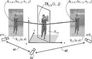
当該描画の際には、逆投影面Pt,k上の同一位置(i,j)のテクスチャTXt,k(i,j)が、複数のカメラ画像Vc,t(u,v)(c=1,2,…,n)内の再投影領域Sc,t,k(u,v)の対応位置(u[i,v],v[i,v])cからそれぞれ描画されて得られることとなる。従って、描画部7では、以下の加算式に模式的に示されるように、当該描画に用いる複数のカメラcからの画素をどのように配分してテクスチャTXt,k(i,j)を得るかを決定したうえで、当該配分に従って描画を行うこととなる。以下の加算式では「Ec」がカメラcの画素「Vc,t(u[i,v],v[i,v])」の配分の割合を表す係数である。
TXt,k(i,j)=Σc Ec* Vc,t(u[i,v],v[i,v])At the time of the drawing,the texture TX t, k (i, j) at the same position (i, j) on theback projection plane P t, k is a plurality of camera images Vc, t (u, v) (Draws from the corresponding positions (u [i, v] , v[i, v] )c of thereprojection area S c, t, k (u, v) in c = 1,2,…, n) It will be obtained. Therefore, in the
TXt, k (i, j) = Σc Ec * Vc, t (u[i, v] , v[i, v] )
ここで、当該配分して描画する手法に関して、種々の実施形態が可能である。 Here, various embodiments are possible with respect to the method of allocating and drawing.
第一実施形態では、カメラcの配分係数Ecを、当該カメラcの位置(及び向き)と、指定されている仮想視点CVの位置(及び向き)と、が近いほど、当該係数の値を大きくして重点的に当該近いカメラcの画素が配分されるようにしてよい。なお、カメラの位置(及び向き)の近さの評価は、仮想視点CVに近いカメラc=1,2,…,nを決定した際と同じ評価を用いればよい。In the first embodiment, the closer the distribution coefficient E c of the camera c is to the position (and orientation) of the camera c and the position (and orientation) of the designated virtual viewpoint CV, the more the value of the coefficient is set. The pixels of the camera c that are close to each other may be distributed in an enlarged manner. The closeness of the camera position (and orientation) may be evaluated by using the same evaluation as when the cameras c = 1,2, ..., N close to the virtual viewpoint CV are determined.
第二実施形態では、カメラcの配分係数Ecを、当該描画に用いるカメラcの画素「Vc,t(u[i,v],v[i,v])」に対して付与部9から与えられている制御値dc,t,k-1(u[i,v],v[i,v])、すなわち既に描画に利用された回数が多いほど、小さくなるように設定することができる。第二実施形態によれば、ある時点で描画に用いられた画素はその後、描画への影響が小さくなることとなる。特別の場合として、1回でも描画に用いられたのであれば配分係数Ec=0とすることで、その後は描画に利用しないようにフラグ付与することもできる。同様に、所定の上限回数に到達した時点で配分係数Ec=0としてもよい。In the second embodiment, the distribution coefficient Ec of the camera c is given to the pixels “Vc, t (u[i, v] , v[i, v] )” of the camera c used for the drawing. The control value dc, t, k-1 (u[i, v] , v[i, v] ) given by, that is, the more times it has already been used for drawing, the smaller it should be set. Can be done. According to the second embodiment, the pixels used for drawing at a certain point in time have a small influence on drawing thereafter. As a special case, if it is used for drawing even once, it can be flagged so that it will not be used for drawing after that by setting thepartition coefficient E c = 0.Similarly, the partition coefficient E c = 0 may be set when the predetermined upper limit is reached.
なお、第二実施形態では、カメラcの配分係数Ecは、描画先の位置(i,j)に対応する描画元の位置(u[i,v],v[i,v])ごとの係数Ec(u[i,v],v[i,v])となる。また、k=1の初回の描画においては未描画の状態である(制御値dc,t,0がステップS1で与えた初期値である)ため、第二実施形態による配分係数Ecは全て等しくなる。In the second embodiment, the distribution coefficient Ecof the camera c is set for each drawing source position (u [i, v] , v[i, v] ) corresponding to the drawing destination position (i, j). The coefficient Ec (u[i, v] , v[i, v] ). Further, since the first drawing with k = 1 is in an undrawn state (control values dc, t, 0 are the initial values given in step S1),all the distribution coefficients E c according to the second embodiment are all. Become equal.
当該配分に関する第一実施形態と第二実施形態とは組み合わせることも可能である。なお、配分係数Ecは第一実施形態及び/又は第二実施形態で求めたうえで、全カメラc=1,2,…,nでの総和が1となるように規格化したうえで、描画を行うようにすればよい。It is also possible to combine the first embodiment and the second embodiment regarding the allocation. The partition coefficient Ec is obtained in the first embodiment and / or the second embodiment, and is standardized so that the sum of all cameras c = 1, 2, ..., N is 1. You just have to draw.
すなわち、当該配分して描画する手法に関して、前述のように配分係数Ecで重みづけ和を取ることに関して具体的に、アルファブレンドにより重ね合わせるようにしてもよい。(なお、各配分係数Ecに関して、0≦Ec≦1の範囲で設定し、テクスチャをTXt,k(i,j)を得るための係数Ecの総和Σc Ecの値が1に正規化されるような重みづけ和がアルファブレンドに相当する。)That is, with respect to the method of drawing by allocating, as described above, thesum of weights with the allocation coefficient E c may be specifically superimposed by alpha blending. (For each distribution coefficient Ec , set in the range of 0 ≤ Ec ≤ 1 and the sumof the coefficients E cto obtain TX t, k (i, j) forthe texture Σ c Ec is 1. The weighted sum that is normalized to is equivalent to an alpha blend.)
この場合、所定関数gを用いて制御値dc,t,k-1(u[i,v],v[i,v])からアルファ値αc,t,k-1(u[i,v],v[i,v])を以下のように求めたうえで、当該アルファ値αc,t,k-1(u[i,v],v[i,v])を用いてアルファブレンドを行うようにすればよい。所定関数gは配分係数Ecに関する第二実施形態と概ね同様に、制御値dc,t,k-1(u[i,v],v[i,v])すなわち既に描画に用いられた回数が大きいほど透過度を増すような関数を用いればよい。
αc,t,k-1(u[i,v],v[i,v])=g(dc,t,k-1(u[i,v],v[i,v]))In this case, the alpha values αc, t, k-1 (u[i,v]) from the control values d c, t, k-1 (u[i, v] , v[i, v]) using the predetermined function g.After finding v] , v[i, v] ) as follows, alpha using the relevant alpha value αc, t, k-1 (u[i, v] , v[i, v] ) You just have to do the blending. The predetermined function g hasthe control values d c, t, k-1 (u[i, v] , v[i, v] ), that is, already used for drawing, in the same manner as in the second embodiment regarding thepartition function E c. A function may be used in which the transparency increases as the number of times increases.
αc, t, k-1 (u[i, v] , v[i, v] ) = g (dc, t, k-1 (u[i, v] , v[i, v] ))
ここで、上記求めたアルファ値αc,t,k-1(u[i,v],v[i,v])は全カメラc=1,2,…,nでの総和が1となるように規格化してもよい。Here, the sum of the alpha values αc, t, k-1 (u[i, v] , v[i, v] ) obtained above for all cameras c = 1,2,…, n is 1. It may be standardized as follows.
例えば、図7のカメラc=1,2の例に関して、(配分係数Ecに関する第一実施形態と同様に)カメラからの距離m1,m2をも考慮したうえで、アルファブレンドを行う場合、以下のようにアルファブレンド結果を得ることができる。
TXt,k(i,j)=α*{1-m1/(m1+m2)}*V1,t(u[i,v],v[i,v])
+[1-m2/(m1+m2)+(1-α)*{1- m1/(m1+m2)}]*V2,t(u[i,v],v[i,v])
ここで、α=α1,t,k-1(u[i,v],v[i,v])、すなわちαはカメラc=1のアルファ値である。For example, for an example of a camera c = 1, 2 of FIG. 7, in consideration also the distance m1, m2 of the (first embodiment similarly to on the allocation coefficient Ec) camera, when performing alpha blending, or less You can get the alpha blend result like this.
TXt, k (i, j) = α * {1-m1 / (m1 + m2)} * V1, t (u[i, v] , v[i, v] )
+ [1-m2 / (m1 + m2) + (1-α) * {1-m1 / (m1 + m2)}] * V2,t (u[i, v] , v[i, v] )
Here, α = α1, t, k-1 (u[i, v] , v[i, v] ), that is, α is the alpha value of the camera c = 1.
当該アルファブレンド例は、カメラc=1のアルファ値によって減少した分(カメラc=1のテクスチャ描画が透明化された分)をカメラc=2に分配し、そのテクスチャの不透明度を増すという処理の例となっている。全く同様にして、α、βをカメラc=1,2のアルファ値として、一般には以下の式を用いてもよい。
TXt,k(i,j)=[α*{1-m1/(m1+m2)} +(1-β)*{1- m2/(m1+m2)}]*V1,t(u[i,v],v[i,v])
+[β*{1-m2/(m1+m2)}+(1-α)*{1- m1/(m1+m2)}]*V2,t(u[i,v],v[i,v])
上記の式において明らかなように、V1,t(u[i,v],v[i,v])及びV2,t(u[i,v],v[i,v])のそれぞれの係数は、カメラc=1,2の区別と、その距離m1,m2と、の両方を考慮した、規格化されたアルファ値となっている。
また、カメラが3個以上の場合も同様に、アルファ値により透明化されたカメラのテクスチャ分をその他のカメラに分配するようにすればよい。In the alpha blend example, the amount reduced by the alpha value of camera c = 1 (the amount that the texture drawing of camera c = 1 is made transparent) is distributed to camera c = 2 and the opacity of the texture is increased. It is an example of. In exactly the same manner, the following equation may be generally used with α and β as the alpha values of the cameras c = 1,2.
TXt, k (i, j) = [α * {1-m1 / (m1 + m2)} + (1-β) * {1-m2 / (m1 + m2)}] * V1, t (u)[i, v] , v[i, v] )
+ [β * {1-m2 / (m1 + m2)} + (1-α) * {1-m1 / (m1 + m2)}] * V2, t (u[i, v] , v[i , v] ))
As is clear from the above equation, V1, t (u[i, v] , v[i, v] ) and V2, t (u[i, v] , v[i, v] ), respectively. The coefficient of is a standardized alpha value that takes into account both the distinction between cameras c = 1 and 2 and the distances m1 and m2.
Similarly, when there are three or more cameras, the texture of the camera made transparent by the alpha value may be distributed to other cameras.
<ステップS4>
ステップS4では、直近のステップS3での描画部7での描画結果に基づき、付与部9が次(k+1回目)のステップS3で描画部7が用いるための制御値dc,t,k+1(u,v)を求めてからステップS5へと進む。前述の通り、当該制御値dc,t,k+1(u,v)は、カメラcの画像Vc,t(u,v)の画素(u,v)が当該時点までに描画に用いられた回数として求めればよい。<Step S4>
In step S4, the control values d c, t, k for the
<ステップS5>
ステップS5では全ての逆投影面Pt,k(i,j)についての描画が完了したか否かを判定し、完了していれば、すなわち当該時点でのk=KであればステップS7へと進み、完了していなければ、すなわちk<KであればステップS6へと進む。<Step S5>
In step S5, it is determined whether or not the drawing for all the back projection planes Pt, k (i, j) is completed, and if it is completed, that is, if k = K at that time, the process proceeds to step S7. Proceed and if not completed, that is, if k <K, proceed to step S6.
<ステップS6>
ステップS6ではkに次の値k+1を設定して、すなわちkの値を1だけ増分してからステップS2に戻る。<Step S6>
In step S6, k is set to the next value, k + 1, that is, the value of k is incremented by 1, and then the process returns to step S2.
<ステップS7>
ステップS7では、以上のK回の繰り返しで全ての逆投影面Pt,k(i,j)(k=1,2,…,K)に関して得られているテクスチャTX t,k(i,j)(当該テクスチャはすなわちxyz空間内での対象の描画結果となっている)を、描画部7が仮想視点CVの画像平面(u,v)へと投影することで対象(前景)のレンダリング結果を得ると共に、背景を前述の通り公知手法でレンダリングすることにより、合成映像SYt(u,v)を得て、当該フローは終了する。<Step S7>
In step S7, the texture TX t, k (i, j) obtained for all the back projection planes Pt, k (i, j) (k = 1,2,…, K) by repeating the above K times. ) (The texture is the drawing result of the target in the xyz space), and the
以上、本発明によれば、インデクスkで指定される順番で逆投影面Pt,k(i,j)に描画することにより、及び、合成映像SYt(u,v)を得る際のレンダリングに関してアルファ値等によるカメラ間での配分を行うことにより、先行手法としての特許文献1における自由視点映像合成のもつ高速な処理形態(リアルタイム性)を損なわずに、オクルージョンによる品質低下の問題を解決することができる。以下、本発明における説明上の補足を述べる。As described above, according to the present invention, rendering is performed by drawing on theback projection planes P t, k(i, j) in the order specified by the index k, and when obtaining the composite image SY t (u, v). By allocating between cameras according to the alpha value, etc., the problem of quality deterioration due to occlusion is solved without impairing the high-speed processing form (real-time property) of free-viewpoint video compositing in
(1)描画部7による処理(図7のステップS7)では、逆投影面Pt,k上の異なる複数の位置(i,j)(実数i,jによる位置)のテクスチャTXt,k(i,j)が、合成画像SYt(u,v)における同一の画素(u,v)(整数)へと逆投影されて対応するものとなっていることもありうる。このような場合に関しては、GPU等の実装に応じた処理で扱うようにすればよい。例えば、当該複数の位置(i,j)(例えば、(0.1, 0.1), (0.11, 0.09), (0.09, 0.11)の3つの互いに近接する位置など)のテクスチャの平均値として求める等してよい。(1) In the processing by the drawing section 7 (step S7 in FIG. 7), back projection plane Pt, a plurality of different positions on thek (i, j) texture TXt of (real i, position byj), k ( It is possible that i, j) is back-projected onto the same pixel (u, v) (integer)in the composite image SY t (u, v) to correspond. In such a case, it may be handled by processing according to the implementation of GPU or the like. For example, it is calculated as the average value of the textures of the plurality of positions (i, j) (for example, three positions (0.1, 0.1), (0.11, 0.09), (0.09, 0.11) that are close to each other). Good.
(2)本発明の合成装置10は、一般的な構成のコンピュータとして実現可能である。すなわち、CPU(中央演算装置)及びGPU(グラフィック処理装置)、当該CPU等にワークエリアを提供する主記憶装置、ハードディスクやSSDその他で構成可能な補助記憶装置、キーボード、マウス、タッチパネルその他といったユーザからの入力を受け取る入力インタフェース、ネットワークに接続して通信を行うための通信インタフェース、表示を行うディスプレイ、カメラ及びこれらを接続するバスを備えるような、一般的なコンピュータによって合成装置10を構成することができる。また、合成装置10の各部の処理はそれぞれ、当該処理を実行させるプログラムを読み込んで実行するCPU及び/又はGPUによって実現することができるが、任意の一部の処理を別途の専用回路等において実現するようにしてもよい。(2) The synthesizer 10 of the present invention can be realized as a computer having a general configuration. That is, from users such as CPU (central processing unit) and GPU (graphic processing unit), main storage device that provides a work area for the CPU, auxiliary storage device that can be configured with a hard disk, SSD, etc., keyboard, mouse, touch panel, etc. The synthesizer 10 can be configured by a common computer, including an input interface for receiving the input of the CPU, a communication interface for connecting to a network and communicating, a display for displaying, a camera, and a bus for connecting them. it can. Further, the processing of each part of the synthesizer 10 can be realized by the CPU and / or GPU that reads and executes the program that executes the processing, but any part of the processing can be realized by a separate dedicated circuit or the like. You may try to do it.
10…合成装置、1…校正部、2…抽出部、3…算出部、4…面群設定部、5…順設定部、6…逆投影部、7…描画部、8…再投影部、9…付与部、20…レンダリング部 10 ... synthesizer, 1 ... calibration unit, 2 ... extraction unit, 3 ... calculation unit, 4 ... surface group setting unit, 5 ... forward setting unit, 6 ... back projection unit, 7 ... drawing unit, 8 ... reprojection unit, 9 ... Grant part, 20 ... Rendering part
Claims (11)
Translated fromJapanese前記尤度画像の各々を3次元空間内に配置された複数の逆投影平面へと逆投影して各々の逆投影平面上で各々の尤度画像の尤度を積算したものとして逆投影データを得る逆投影部と、
前記逆投影データの尤度によって前景領域を判定し、当該前景領域を前記多視点画像の各々へと投影して再投影領域を定め、前記多視点画像の全部又は一部の視点画像のテクスチャのうち当該再投影領域に属するものを、前記複数の逆投影平面へと順番に逆投影して描画して前記対象をレンダリングすることで、前記対象の自由視点画像を合成する描画部と、を備えることを特徴とした合成装置。A calculation unit that obtains the likelihood image of the target area captured from each viewpoint image of the multi-viewpoint image,
Back-projection data isobtained by back-projecting each of the likelihood images onto a plurality of back-projective planes arranged in a three-dimensional spaceand integrating the likelihood of each likelihood image on each back-projection plane. Get back projection and
The foreground region is determined by the likelihood of the back projection data,the foreground region is projected onto each of the multi-viewpoint images to determine the reprojection region, andthe texture of all or part of the viewpoint image of the multi-viewpoint image is determined.Among them, a drawing unit that synthesizes a free viewpoint image of the target by rendering the object belonging to the reprojection region by back-projecting it back onto the plurality of back-projection planes in order and rendering the target is provided. A synthesizer characterized by that.
前記尤度画像の各々を3次元空間内に配置された複数の逆投影平面へと逆投影して各々の逆投影平面上で各々の尤度画像の尤度を積算したものとして逆投影データを得る逆投影段階と、
前記逆投影データの尤度によって前景領域を判定し、当該前景領域を前記多視点画像の各々へと投影して再投影領域を定め、前記多視点画像の全部又は一部の視点画像のテクスチャのうち当該再投影領域に属するものを、前記複数の逆投影平面へと順番に逆投影して描画して前記対象をレンダリングすることで、前記対象の自由視点画像を合成する描画段階と、を備えることを特徴とした合成方法。The calculation stage for obtaining the likelihood image of the target area captured from each viewpoint image of the multi-viewpoint image, and
Back-projection data isobtained by back-projecting each of the likelihood images onto a plurality of back-projective planes arranged in a three-dimensional spaceand integrating the likelihood of each likelihood image on each back-projection plane. To get the back projection stage and
The foreground region is determined by the likelihood of the back projection data,the foreground region is projected onto each of the multi-viewpoint images to determine the reprojection region, andthe texture of all or part of the viewpoint image of the multi-viewpoint image is determined.Among them, those belonging to the reprojection region are sequentially back-projected onto the plurality of back-projection planes and drawn to render the target, thereby comprising a drawing step of synthesizing the free-viewpoint image of the target. A synthetic method characterized by that.
多視点画像の各視点画像から撮影されている対象の領域の尤度画像を求める算出部と、
前記尤度画像の各々を3次元空間内に配置された複数の逆投影平面へと逆投影して各々の逆投影平面上で各々の尤度画像の尤度を積算したものとして逆投影データを得る逆投影部と、
前記逆投影データの尤度によって前景領域を判定し、当該前景領域を前記多視点画像の各々へと投影して再投影領域を定め、前記多視点画像の全部又は一部の視点画像のテクスチャのうち当該再投影領域に属するものを、前記複数の逆投影平面へと順番に逆投影して描画して前記対象をレンダリングすることで、前記対象の自由視点画像を合成する描画部と、を備える合成装置として機能させることを特徴とするプログラム。A computer, a synthesizer
A calculation unit that obtains the likelihood image of the target area captured from each viewpoint image of the multi-viewpoint image,
Back-projection data isobtained by back-projecting each of the likelihood images onto a plurality of back-projective planes arranged in a three-dimensional spaceand integrating the likelihood of each likelihood image on each back-projection plane. Get back projection and
The foreground region is determined by the likelihood of the back projection data,the foreground region is projected onto each of the multi-viewpoint images to determine the reprojection region, andthe texture of all or part of the viewpoint image of the multi-viewpoint image is determined.Among them, a drawing unit that synthesizes a free viewpoint image of the target by rendering the object belonging to the reprojection region by back-projecting it back onto the plurality of back-projection planes in order and rendering the target is provided. A program characterized by functioning as a synthesizer.
Priority Applications (1)
| Application Number | Priority Date | Filing Date | Title |
|---|---|---|---|
| JP2018034847AJP6898264B2 (en) | 2018-02-28 | 2018-02-28 | Synthesizers, methods and programs |
Applications Claiming Priority (1)
| Application Number | Priority Date | Filing Date | Title |
|---|---|---|---|
| JP2018034847AJP6898264B2 (en) | 2018-02-28 | 2018-02-28 | Synthesizers, methods and programs |
Publications (2)
| Publication Number | Publication Date |
|---|---|
| JP2019149112A JP2019149112A (en) | 2019-09-05 |
| JP6898264B2true JP6898264B2 (en) | 2021-07-07 |
Family
ID=67849446
Family Applications (1)
| Application Number | Title | Priority Date | Filing Date |
|---|---|---|---|
| JP2018034847AActiveJP6898264B2 (en) | 2018-02-28 | 2018-02-28 | Synthesizers, methods and programs |
Country Status (1)
| Country | Link |
|---|---|
| JP (1) | JP6898264B2 (en) |
Families Citing this family (2)
| Publication number | Priority date | Publication date | Assignee | Title |
|---|---|---|---|---|
| JP7078564B2 (en)* | 2019-02-21 | 2022-05-31 | Kddi株式会社 | Image processing equipment and programs |
| JP7405702B2 (en)* | 2020-06-15 | 2023-12-26 | Kddi株式会社 | Virtual viewpoint rendering device, method and program |
Family Cites Families (3)
| Publication number | Priority date | Publication date | Assignee | Title |
|---|---|---|---|---|
| JP4828506B2 (en)* | 2007-11-05 | 2011-11-30 | 日本電信電話株式会社 | Virtual viewpoint image generation device, program, and recording medium |
| JP5361758B2 (en)* | 2010-02-12 | 2013-12-04 | 日本電信電話株式会社 | Image generation method, image generation apparatus, and program |
| JP2016001386A (en)* | 2014-06-11 | 2016-01-07 | 日本電信電話株式会社 | Image generation method, image generation apparatus, computer program, and recording medium |
- 2018
- 2018-02-28JPJP2018034847Apatent/JP6898264B2/enactiveActive
Also Published As
| Publication number | Publication date |
|---|---|
| JP2019149112A (en) | 2019-09-05 |
Similar Documents
| Publication | Publication Date | Title |
|---|---|---|
| EP3827299B1 (en) | Mixed reality system with virtual content warping and method of generating virtual content using same | |
| CN111508052B (en) | Rendering method and device of three-dimensional grid body | |
| US9020241B2 (en) | Image providing device, image providing method, and image providing program for providing past-experience images | |
| US5694533A (en) | 3-Dimensional model composed against textured midground image and perspective enhancing hemispherically mapped backdrop image for visual realism | |
| CN102834849B (en) | Carry out the image displaying device of the description of three-dimensional view picture, image drawing method, image depiction program | |
| US5613048A (en) | Three-dimensional image synthesis using view interpolation | |
| KR101724360B1 (en) | Mixed reality display apparatus | |
| CN111656407A (en) | Fusing, texturing, and rendering views of a dynamic three-dimensional model | |
| Goesele et al. | Ambient point clouds for view interpolation | |
| CN114066715B (en) | Image style transfer method, device, electronic device and storage medium | |
| AU2693700A (en) | Method and apparatus for processing images | |
| GB2406252A (en) | Generation of texture maps for use in 3D computer graphics | |
| US12347022B2 (en) | Method and system for generating a target image from plural multi-plane images | |
| JP2021056679A (en) | Image processing apparatus, method and program | |
| KR102059732B1 (en) | Digital video rendering | |
| US20230230311A1 (en) | Rendering Method and Apparatus, and Device | |
| JP2021022032A (en) | Synthesizer, method and program | |
| US12020363B2 (en) | Surface texturing from multiple cameras | |
| JP2023153534A (en) | Image processing apparatus, image processing method, and program | |
| CN117557721A (en) | A single image detail three-dimensional face reconstruction method, system, equipment and medium | |
| JP6898264B2 (en) | Synthesizers, methods and programs | |
| Shi et al. | Stereo-consistent screen-space ambient occlusion | |
| JP7476511B2 (en) | Image processing system, image processing method and program | |
| CN117315154B (en) | Quantifiable face model reconstruction method and system | |
| CN120259520A (en) | Element rendering method, device, equipment, storage medium and program product |
Legal Events
| Date | Code | Title | Description |
|---|---|---|---|
| A621 | Written request for application examination | Free format text:JAPANESE INTERMEDIATE CODE: A621 Effective date:20200109 | |
| A131 | Notification of reasons for refusal | Free format text:JAPANESE INTERMEDIATE CODE: A131 Effective date:20210331 | |
| A521 | Written amendment | Free format text:JAPANESE INTERMEDIATE CODE: A523 Effective date:20210521 | |
| TRDD | Decision of grant or rejection written | ||
| A01 | Written decision to grant a patent or to grant a registration (utility model) | Free format text:JAPANESE INTERMEDIATE CODE: A01 Effective date:20210602 | |
| A61 | First payment of annual fees (during grant procedure) | Free format text:JAPANESE INTERMEDIATE CODE: A61 Effective date:20210610 | |
| R150 | Certificate of patent or registration of utility model | Ref document number:6898264 Country of ref document:JP Free format text:JAPANESE INTERMEDIATE CODE: R150 |