JP6898122B2 - Charger - Google Patents
ChargerDownload PDFInfo
- Publication number
- JP6898122B2 JP6898122B2JP2017057517AJP2017057517AJP6898122B2JP 6898122 B2JP6898122 B2JP 6898122B2JP 2017057517 AJP2017057517 AJP 2017057517AJP 2017057517 AJP2017057517 AJP 2017057517AJP 6898122 B2JP6898122 B2JP 6898122B2
- Authority
- JP
- Japan
- Prior art keywords
- battery
- charging
- charger
- opening
- connection
- Prior art date
- Legal status (The legal status is an assumption and is not a legal conclusion. Google has not performed a legal analysis and makes no representation as to the accuracy of the status listed.)
- Active
Links
Images


Classifications
- H—ELECTRICITY
- H02—GENERATION; CONVERSION OR DISTRIBUTION OF ELECTRIC POWER
- H02J—CIRCUIT ARRANGEMENTS OR SYSTEMS FOR SUPPLYING OR DISTRIBUTING ELECTRIC POWER; SYSTEMS FOR STORING ELECTRIC ENERGY
- H02J7/00—Circuit arrangements for charging or depolarising batteries or for supplying loads from batteries
- H02J7/0042—Circuit arrangements for charging or depolarising batteries or for supplying loads from batteries characterised by the mechanical construction
- H02J7/0045—Circuit arrangements for charging or depolarising batteries or for supplying loads from batteries characterised by the mechanical construction concerning the insertion or the connection of the batteries
- H—ELECTRICITY
- H01—ELECTRIC ELEMENTS
- H01M—PROCESSES OR MEANS, e.g. BATTERIES, FOR THE DIRECT CONVERSION OF CHEMICAL ENERGY INTO ELECTRICAL ENERGY
- H01M10/00—Secondary cells; Manufacture thereof
- H01M10/42—Methods or arrangements for servicing or maintenance of secondary cells or secondary half-cells
- H01M10/44—Methods for charging or discharging
- H01M10/441—Methods for charging or discharging for several batteries or cells simultaneously or sequentially
- H—ELECTRICITY
- H01—ELECTRIC ELEMENTS
- H01M—PROCESSES OR MEANS, e.g. BATTERIES, FOR THE DIRECT CONVERSION OF CHEMICAL ENERGY INTO ELECTRICAL ENERGY
- H01M10/00—Secondary cells; Manufacture thereof
- H01M10/42—Methods or arrangements for servicing or maintenance of secondary cells or secondary half-cells
- H01M10/44—Methods for charging or discharging
- H01M10/443—Methods for charging or discharging in response to temperature
- H—ELECTRICITY
- H02—GENERATION; CONVERSION OR DISTRIBUTION OF ELECTRIC POWER
- H02J—CIRCUIT ARRANGEMENTS OR SYSTEMS FOR SUPPLYING OR DISTRIBUTING ELECTRIC POWER; SYSTEMS FOR STORING ELECTRIC ENERGY
- H02J7/00—Circuit arrangements for charging or depolarising batteries or for supplying loads from batteries
- H02J7/00047—Circuit arrangements for charging or depolarising batteries or for supplying loads from batteries with provisions for charging different types of batteries
- H—ELECTRICITY
- H02—GENERATION; CONVERSION OR DISTRIBUTION OF ELECTRIC POWER
- H02J—CIRCUIT ARRANGEMENTS OR SYSTEMS FOR SUPPLYING OR DISTRIBUTING ELECTRIC POWER; SYSTEMS FOR STORING ELECTRIC ENERGY
- H02J7/00—Circuit arrangements for charging or depolarising batteries or for supplying loads from batteries
- H02J7/0013—Circuit arrangements for charging or depolarising batteries or for supplying loads from batteries acting upon several batteries simultaneously or sequentially
- Y—GENERAL TAGGING OF NEW TECHNOLOGICAL DEVELOPMENTS; GENERAL TAGGING OF CROSS-SECTIONAL TECHNOLOGIES SPANNING OVER SEVERAL SECTIONS OF THE IPC; TECHNICAL SUBJECTS COVERED BY FORMER USPC CROSS-REFERENCE ART COLLECTIONS [XRACs] AND DIGESTS
- Y02—TECHNOLOGIES OR APPLICATIONS FOR MITIGATION OR ADAPTATION AGAINST CLIMATE CHANGE
- Y02E—REDUCTION OF GREENHOUSE GAS [GHG] EMISSIONS, RELATED TO ENERGY GENERATION, TRANSMISSION OR DISTRIBUTION
- Y02E60/00—Enabling technologies; Technologies with a potential or indirect contribution to GHG emissions mitigation
- Y02E60/10—Energy storage using batteries
Landscapes
- Engineering & Computer Science (AREA)
- Power Engineering (AREA)
- Manufacturing & Machinery (AREA)
- Chemical & Material Sciences (AREA)
- Chemical Kinetics & Catalysis (AREA)
- Electrochemistry (AREA)
- General Chemical & Material Sciences (AREA)
- Charge And Discharge Circuits For Batteries Or The Like (AREA)
- Secondary Cells (AREA)
Description
Translated fromJapanese本開示は、装着部の異なる複数のスライド式バッテリを充電する充電器に関する。 The present disclosure relates to a charger that charges a plurality of sliding batteries having different mounting portions.
特許文献1には、二つの接続部を備え、同じ装着部の二つのスライド式バッテリを同時に装着することができる充電器が開示されている。 Patent Document 1 discloses a charger having two connecting portions and capable of simultaneously mounting two sliding batteries having the same mounting portion.
スライド式バッテリには、電圧の違いなどに応じて装着部の異なる複数の種類が存在する。特許文献1に記載の充電器は、二つの接続部を備えているものの、異なる装着部の二つのバッテリを装着できるようにはなっていない。よって、装着部の異なる複数のバッテリを所有するユーザは、それぞれの装着部に応じた充電器を購入し管理しなければならないという問題がある。 There are a plurality of types of sliding batteries having different mounting portions depending on the difference in voltage and the like. Although the charger described in Patent Document 1 has two connecting portions, it is not capable of mounting two batteries having different mounting portions. Therefore, there is a problem that a user who owns a plurality of batteries having different mounting portions must purchase and manage a charger corresponding to each mounting portion.
本開示の一局面は、装着部の異なる複数のスライド式のバッテリを、1台の充電器で充電できるようにすることを目的とする。 One aspect of the present disclosure is to enable a single charger to charge a plurality of sliding batteries having different mounting portions.
本開示の一局面における充電器は、複数の接続部と、1つの電源回路と、複数の充電経路と、複数の開閉部と、充電制御部と、を備える。
複数の接続部は、装着部が異なる少なくとも2つのスライド式のバッテリが装着される。電源回路は、入力電力から充電電力を生成する。複数の充電経路は、電源回路と複数の接続部のそれぞれとを接続する。複数の開閉部は、複数の充電経路のそれぞれに設けられ、閉状態にて充電経路を接続状態にし、開状態にて充電経路を切断状態にする。The charger in one aspect of the present disclosure includes a plurality of connection portions, one power supply circuit, a plurality of charging paths, a plurality of opening / closing portions, and a charging control unit.
The plurality of connections are fitted with at least two sliding batteries with different mounting portions. The power supply circuit generates charging power from the input power. The plurality of charging paths connect the power supply circuit and each of the plurality of connections. The plurality of opening / closing portions are provided in each of the plurality of charging paths, and the charging path is connected in the closed state and the charging path is disconnected in the open state.
充電制御部は、複数の接続部のいずれか1つに接続されているバッテリを充電対象とし、複数の開閉部のうち、充電対象が接続部を介して接続されている充電経路に設けられた開閉部を閉状態にして、充電対象に適した充電電流で予め決められた電圧まで充電対象を充電する。 The charge control unit targets the battery connected to any one of the plurality of connection units as a charging target, and is provided in the charging path in which the charging target is connected via the connection unit among the plurality of opening / closing units. The opening / closing part is closed, and the charging target is charged to a predetermined voltage with a charging current suitable for the charging target.
上記充電器によれば、充電器に装着部の異なる複数のスライド式のバッテリを接続できる。そして、充電器に接続されたバッテリのうちの1つが充電対象とされ、充電対象と電源回路とを接続する充電経路が接続状態にされ、充電対象が充電される。充電器に複数のバッテリが接続されている場合は、充電対象を順次替えることで、すべてのバッテリを充電することができる。したがって、装着部の異なる複数のスライド式のバッテリを、1台の充電器で充電することができる。 According to the above charger, a plurality of sliding batteries having different mounting portions can be connected to the charger. Then, one of the batteries connected to the charger is set as the charging target, the charging path connecting the charging target and the power supply circuit is connected, and the charging target is charged. When a plurality of batteries are connected to the charger, all the batteries can be charged by sequentially changing the charging target. Therefore, a plurality of slide-type batteries having different mounting portions can be charged by one charger.
上記充電器は、複数の充電経路が複数の開閉部のそれぞれに向かって分岐する分岐点と、複数の接続部のそれぞれとの間に設けられ、接続部の側から分岐点へ向かう電流の逆流を防止する複数の逆流防止部を備えていてもよい。 The charger is provided between a branch point where a plurality of charging paths branch toward each of the plurality of opening / closing portions and each of the plurality of connecting portions, and a backflow of current from the connection portion side toward the branch point. It may be provided with a plurality of backflow prevention portions for preventing the above.
これにより、接続部に接続されているバッテリが充電対象外となっている場合には、開状態になっている開閉部と逆流防止部により、充電対象外のバッテリから分岐点への電流の逆流が防止される。よって、開閉部に加えて逆流防止部も設けたことにより、より安全性を高めることができる。 As a result, when the battery connected to the connection part is not subject to charging, the backflow of current from the battery not subject to charging to the branch point is caused by the open / close part and the backflow prevention part. Is prevented. Therefore, the safety can be further improved by providing the backflow prevention portion in addition to the opening / closing portion.
また、上記充電器は、充電制御部により充電対象の充電が開始される前に、複数の開閉部を診断する診断部を備えていてもよい。
充電開始前に、複数の開閉部を診断することにより、いずれかの開閉部が故障している場合には、充電を中止することができるため、より安全性を高めることができる。Further, the charger may include a diagnostic unit that diagnoses a plurality of opening / closing units before the charging control unit starts charging the charging target.
By diagnosing a plurality of opening / closing portions before starting charging, if any of the opening / closing portions is out of order, charging can be stopped, so that safety can be further improved.
また、充電制御部は、複数の接続部に少なくとも2つのバッテリが接続されており、且つ、少なくとも2つのバッテリの中に、バッテリ温度がバッテリごとに設定された温度閾値を超えているバッテリが含まれている場合に、バッテリ温度が温度閾値を超えているバッテリを待機状態にし、他のバッテリを優先的に充電するようにしてもよい。 Further, the charge control unit includes a battery in which at least two batteries are connected to a plurality of connection units and the battery temperature exceeds the temperature threshold set for each battery among at least two batteries. If this is the case, the battery whose battery temperature exceeds the temperature threshold may be put into a standby state, and other batteries may be preferentially charged.
このようにすることにより、バッテリ温度が温度閾値を超えているバッテリが充電器に接続されている場合には、そのバッテリはバッテリ温度が温度閾値よりも低下するまで待機状態にされ、その間に、他のバッテリが優先的に充電される。よって、効率的に複数のバッテリを充電することができる。 By doing so, if a battery whose battery temperature exceeds the temperature threshold is connected to the charger, the battery will be put into a standby state until the battery temperature drops below the temperature threshold. Other batteries are preferentially charged. Therefore, it is possible to efficiently charge a plurality of batteries.
また、電源回路と、複数の充電経路と、複数の開閉部と、充電制御部と、を収納し、1つの面に接続部が設けられたケースを備えていてもよい。そして、ケースは、接続部が設けられた面とは異なる面から突出するように設けられた少なくとも1つの取り付け部を備え、取り付け部には、充電器が取り付けられる取り付け面に設けられた突起に嵌合させる嵌合孔が形成されていてもよい。 Further, a case may be provided in which a power supply circuit, a plurality of charging paths, a plurality of opening / closing portions, and a charging control unit are housed, and a connecting portion is provided on one surface. The case is provided with at least one mounting portion provided so as to project from a surface different from the surface on which the connecting portion is provided, and the mounting portion is formed on a protrusion provided on the mounting surface on which the charger is mounted. A fitting hole for fitting may be formed.
これにより、取り付け面に設けられた突起に、取り付け部の嵌合孔を嵌合させることで、充電器を取り付け面に取り付けて使用することができる。さらに、嵌合孔が形成された取り付け部が、ケースの面から突出するように設けられているため、ケースの面に嵌合孔を形成した場合と比べて、ケース内への突起の侵入を抑制できる。ひいては、ケース内の空間を有効に利用して、回路基板などを収納することができる。 As a result, the charger can be attached to the attachment surface and used by fitting the fitting hole of the attachment portion into the protrusion provided on the attachment surface. Further, since the mounting portion having the fitting hole formed is provided so as to protrude from the surface of the case, the protrusion can penetrate into the case as compared with the case where the fitting hole is formed on the surface of the case. Can be suppressed. As a result, the space inside the case can be effectively used to store the circuit board and the like.
以下、図面を参照しながら、本開示を実施するための形態を説明する。本実施形態に係る充電器5は、装着部の異なる2種類のバッテリパックを充電する装置である。
[1.機械的構成]
[1−1.外側の構成]
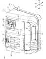
まず、充電器5の外側の機械的構成について、図1〜図5を参照して説明する。充電器5は、樹脂製の筐体であるケース50の1つの面に、2種類のバッテリパックの装着部に対応した第1接続部31及び第2接続部32が設けられ、充電回路が設けられた基板がケース50の内部に収納されて構成されている。ここでは、図1に示すように、第1接続部31及び第2接続部32が設けられた面を正面330、正面330に対向する面を背面410とし、正面330を前方向、背面410を後方向とする。また、第1接続部31及び第2接続部32が並んでいる方向を左右方向、第1接続部31及び第2接続部32の長手方向を上下方向とする。Hereinafter, modes for carrying out the present disclosure will be described with reference to the drawings. The charger 5 according to the present embodiment is a device for charging two types of battery packs having different mounting portions.
[1. Mechanical configuration]
[1-1. Outer configuration]
First, the mechanical configuration on the outside of the charger 5 will be described with reference to FIGS. 1 to 5. The charger 5 is provided with a
充電器5は、正面330の上部に、左右に並んだ第1接続部31及び第2接続部32を備える。また、充電器5は、正面330において、第1接続部31の下側に第1表示部315を備え、第2接続部32の下側に第2表示部325を備える。 The charger 5 includes a
第1接続部31には、図2に示す第1バッテリBaの装着部11が装着される。第1接続部31は、図13に示すように、第1正極側端子91と、第1温度入力端子130、通信端子140と、センス端子150と、第1負極側端子160とを備える。また、第1接続部31は、正面330から前方に突出し、上下方向に延伸した2つのレール部311を備える。2つのレール部311は、所定の間隔を空けて左右方向に並べて設けられており、第1バッテリBaの装着をガイドする。さらに、第1接続部31は、上端部分に凹状に形成された嵌合溝313と、嵌合溝313の下側に形成された送風開口312とを備える。嵌合溝313は、レール部311の延伸方向に垂直な方向に延伸するように設けられている。送風開口312は、後述するケース50内のファン37の前側に設けられている。 The mounting
第1バッテリBaは、樹脂ケース内に、複数の直列接続された電池セルと、制御回路と、電圧検出回路とを備える。第1バッテリBaは、電動工具や園芸器具、現場作業機などに用いられるバッテリパックであり、例えば、リチウムイオンバッテリである。第1バッテリBaの定格電圧は14.4Vまたは18Vである。 The first battery Ba includes a plurality of battery cells connected in series, a control circuit, and a voltage detection circuit in a resin case. The first battery Ba is a battery pack used for electric tools, gardening tools, field work machines, and the like, and is, for example, a lithium ion battery. The rated voltage of the first battery Ba is 14.4V or 18V.
第1バッテリBaは、ケースの背面に装着部11を備える。装着部11は、充電器5の第1接続部31や、第1バッテリBaから電力供給を受けて動作する電動工具に装着される。装着部11は、第1接続部31の第1正極側端子91に接続される充電用正極端子13と、放電用正極端子12aと、第1接続部31の第1負極側端子160に接続される負極端子12bと、第1接続部31の他の端子に接続される接続端子と、を備える。そして、第1バッテリBaは、充電用正極端子13を介して充電電流の供給を受けるとともに、放電用正極端子12aを介して放電電流を出力する。また、第1バッテリBaの制御回路は、第1バッテリBaに関する情報を取得し、充電器5の通信端子140を介して、第1バッテリBaのバッテリに関する情報を示すデジタルデータを充電器5へ出力する。さらに、第1バッテリBaの制御回路は、第1温度入力端子130を介して、第1バッテリBaの状態に関する情報を示すアナログデータを充電器5へ出力する。 The first battery Ba includes a mounting
また、装着部11は、2つのスライドレール14と、嵌合爪16と、吸気口15と、排気口17と、を備える。2つのスライドレール14は、ケースの背面から後方に突出し、上下方向に延伸したレールであり、第1接続部31のレール部311と係合する。嵌合爪16は、スライドレール14の延伸方向に垂直な方向に延伸するように上端部分に設けられており、第1接続部31の嵌合溝313と嵌合する。吸気口15は、嵌合爪16の下側に設けられており、排気口17は、下端部分に設けられている。スライドレール14、嵌合爪16、及び吸気口15は、第1接続部31のレール部311、嵌合溝313、及び送風開口312と対応する位置関係に配置されている。 Further, the mounting
第1バッテリBaを第1接続部31に装着する場合は、2つのレール部311の内面に2つのスライドレール14の外面を係合させて、上側から下側へスライドさせる。第1バッテリBaが、第1接続部31上をスライドして、嵌合溝313に嵌合爪16が嵌合すると、第1バッテリBaのスライドが規制され、第1バッテリBaの装着が完了する。これにより、第1接続部31の各種端子と第1バッテリBaの各種端子とが接続される。そして、ファン37から送られた気体は、送風開口312から吸気口15を通って第1バッテリBa内に入り、第1バッテリBaの内部を冷却して、排気口17から外部へ排出される。また、第1バッテリBaを第1接続部31から取り外す場合は、嵌合溝313と嵌合爪16との嵌合を解除し、第1バッテリBaを下側から上側へスライドさせて取り外せばよい。 When the first battery Ba is attached to the
一方、第2接続部32は、第1接続部31とは形状が異なり、第2接続部32には、図3に示す第2バッテリBbの装着部21が装着される。第2接続部32には、第1バッテリBaの装着部11は装着できないようになっており、第1接続部31には、第2バッテリBbの装着部21は装着できないようになっている。 On the other hand, the shape of the
第2接続部32は、図13に示すように、第2正極側端子92と、電圧検出端子100,110と、第2温度入力端子120と、第2負極側端子170とを備える。また、第2接続部32は、第1接続部31と同様に、正面330から前方に突出して、第2バッテリBbの装着をガイドする2つのレール部321と、凹状に形成された嵌合溝323と、送風開口322とを備える。レール部321、嵌合溝323、及び送風開口322は、それぞれ、レール部311、嵌合溝313、及び送風開口312と寸法や形状は異なるものの、同様の位置関係に配置されている。また、送風開口322の真後ろにも、ファン37が設置されている。 As shown in FIG. 13, the
第2バッテリBbは、樹脂ケース内に、3つの直列接続された電池セルを備える。第2バッテリBbは、電動工具や園芸器具、現場作業機などに用いられるバッテリパックであり、例えば、リチウムイオンバッテリである。また、第2バッテリBbの定格電圧は、10.8Vである。第2バッテリBbは、第1バッテリBaとは異なり、制御回路を備えていない。そのため、充電器5が、電圧検出端子100,110や第2温度入力端子120を用いて、第2バッテリBbのバッテリ状態を検出する。 The second battery Bb includes three battery cells connected in series in a resin case. The second battery Bb is a battery pack used for electric tools, gardening tools, field work machines, and the like, and is, for example, a lithium ion battery. The rated voltage of the second battery Bb is 10.8V. Unlike the first battery Ba, the second battery Bb does not have a control circuit. Therefore, the charger 5 detects the battery state of the second battery Bb by using the
第2バッテリBbは、ケースの背面に装着部21を備える。装着部21は、充電器5の第2接続部32や、第2バッテリBbから電力供給を受けて動作する電動工具などに装着される。装着部21は、第2接続部32の第2正極側端子92に接続される正極端子22aと、第2負極側端子170に接続される負極端子22bと、第2接続部32の他の端子に接続される接続端子と、を備える。 The second battery Bb includes a mounting
また、装着部21は、装着部11と同様に、第2接続部32のレール部321、嵌合溝323、及び送風開口322と対応する位置に、スライドレール24、嵌合爪26、及び吸気口25が設けられているとともに、下端部分に排気口27が設けられている。 Further, like the mounting
そして、第2バッテリBbの第2接続部32への装着の仕方及び取り外し方は、第1バッテリBaと同様である。第2バッテリBbが第2接続部32へ装着されると、第2接続部32の各種端子と第2バッテリBbの各種端子とが接続される。 The method of attaching and detaching the second battery Bb to the
第1表示部315は、緑、赤、黄の3色のLEDを含み、3色のLEDで第1バッテリBaの状態を示す。第1表示部315で示す状態としては、例えば、充電中、待機中、充電完了中などである。同様に、第2表示部325は、3色のLEDで第2バッテリBbの状態を示す。 The
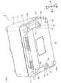
図5は、充電器5を取り付ける取り付け面である壁Wを示す。充電器5は、ケース50の背面を壁Wの側に向けて壁Wに取り付け、使用できるように構成されている。ケース50は、図4に示すように、矩形状に形成された背面を有し、背面の4つの角それぞれに、背面から後方に突出するように形成された脚部420を備える。 FIG. 5 shows a wall W which is a mounting surface for mounting the charger 5. The charger 5 is configured so that the back surface of the
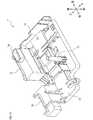
また、ケース50は、背面410の左端部と右端部のそれぞれにおいて、上下方向の略中央に、背面410から後方に突出するように形成された取り付け部41を備える。脚部420と取り付け部41の前後方向の長さは同程度に形成されている。取り付け部41は、ケース50の背面410から後方に向かって立設し、背面410に平行な断面が略半楕円形状の側面41aと、側面41aの後端部に繋がり、背面410に平行な略半楕円形状の板状部材41bと、を含む。そして、板状部材41bには、嵌合孔42が形成されている。嵌合孔42は、壁Wに設けられた突起Fに嵌合させる孔である。突起Fの長さは、取り付け部41の前後方向の長さよりも短く形成されている。 Further, the
さらに、板状部材41bに対向する背面410の部分には、前方に凹んだ溝411が形成されている。また、背面410には、左右の取り付け部41から背面410の上端部へ向けて、上下方向に沿ったライン412が描かれている。このライン412は、背面410の上端部からケース50の上面へ、前後方向に沿って延伸するように描かれている。充電器5を壁Wに取り付ける場合、充電器5の上面に延びているライン412を用いて突起Fと充電器5の左右方向の位置合わせを行い、溝411を用いて突起Fと充電器5の上下方向の位置合わせを行う。そして、2つの取り付け部41の嵌合孔42を、それぞれ突起Fに嵌合させることで、充電器5が壁Wに取り付けられる。 Further, a
なお、取り付け部41の数や背面410での設置位置は、上記記載に限定されるものではない。取り付け部41は、背面410に1つだけ設けられていてもよいし、背面410に3つ以上設けられていてもよい。また、取り付け部41の設置位置は、壁Wにバランスをよく取り付けられる位置であればどこでもよい。さらに、取り付け面は、壁Wに限らず棚の側面などでもよい。 The number of mounting
[1−2.内側の構成]
[1−2−1.後ケースの内側]
次に、充電器5の内側の機械的構成について、図6〜図12を参照して説明する。図1に示すように、充電器5のケース50は、前ケース3と後ケース4とが組み合わさって構成されている。[1-2. Inner configuration]
[1-2-1. Inside the rear case]
Next, the mechanical configuration inside the charger 5 will be described with reference to FIGS. 6 to 12. As shown in FIG. 1, the
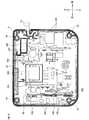
まず、後ケース4の内側の構成について、図6を参照して説明する。図6は、ケース50から前ケース3を取り外し、後ケース4を前方から見た図である。後ケース4は、開口面が矩形状のトレー形状に形成されており、後ケース4の4つの角には、それぞれ、前側へ突出した突起状の凸部43が形成されている。この凸部43が、後述する前ケース3の4つの角に形成されている凹部35に嵌合することで、前ケース3と後ケース4とが組み合った状態で固定され、ケース50が構成される。 First, the configuration inside the
また、後ケース4内には、螺子などで後ケース4に固定されていない状態で、基板45が収納されている。後ケース4の背面410の大きさは、基板45と略等しい大きさになっている。そして、基板45上には、多数の電子部品が取り付けられており、第1バッテリBa及び第2バッテリBbを充電する充電回路が構成されている。基板45の右端部には、電源コードPwが接続されているとともに、メインコンバータ83の平滑コンデンサ457及びノイズフィルタ459が搭載されている。また、基板45の左端部には、基板45に対して垂直に、サブ基板451が搭載されている。サブ基板451には、CPU、ROM、RAMを含むマイクロコンピュータを含み、充電制御を実行する制御部200が搭載されている。また、基板45の中央よりもやや上方には、メインコンバータ83のトランス456が搭載されている。さらに、制御部200を搭載しているサブ基板451とトランス456との間と、平滑コンデンサ457及びノイズフィルタ459とトランス456との間とには、発熱を抑止するためのヒートシンク454,455が搭載されている。 Further, in the
図6に示すように、基板45上では、トランス456及びノイズフィルタ459が大きな面積を占めている。充電器5は、第1接続部31及び第2接続部32の2つの接続部を備えているが、接続部が1つだけの場合と同様に、メインコンバータ83とノイズフィルタ459を1つずつしか備えていない。充電器5に第1バッテリBa及び第2バッテリBbが同時に装着されている場合には、充電器5は、1つのメインコンバータ83により、1つずつ順番にバッテリパックを充電する。つまり、充電器5は、1つのメインコンバータ83及び1つのノイズフィルタ459を、2つのバッテリパックで兼用する。そのため、充電器5は、接続部を2つ備えているものの、大型化が抑制されている。 As shown in FIG. 6, the
さらに、充電器5では、電子部品の一部がサブ基板451に取り付けられ、サブ基板451が基板45に対して垂直に搭載されている。そのため、充電器5の大型化、特に前後方向に垂直な平面の大きさがより抑制され、充電器5は、接続部を1つだけしか備えていない充電器と比べても、あまり変わらない大きさに形成されている。 Further, in the charger 5, a part of the electronic components is attached to the sub-board 451 and the sub-board 451 is mounted perpendicular to the
また、基板45上には、平滑コンデンサ457側と電源コードPwとの間に、ノイズをシールドするノイズ対策用のシールド基板458が基板45に対して垂直に搭載されている。これにより、シールド基板458よりも左側で発生するノイズをシールドすることができる。さらに、サブ基板451とヒートシンク454との間には、絶縁スペーサ453が取り付けられている。これにより、サブ基板451を、絶縁スペーサ453による絶縁間隔でヒートシンク454に支持させることができる。 Further, on the
また、後ケース4の左側面と対向する側のサブ基板451上、及び、後ケース4の左側面とサブ基板451との間の基板45上に、後述する接続コードH3やファンハーネスを接続するための複数のコネクタ452が設けられている。後ケース4の左側面は、サブ基板451に平行且つ最も近い後ケース4の側面である。また、接続コードH3は、第1接続部31及び第2接続部32と基板45とを接続するコードである。このように、サブ基板451の片側の面と、その片側の面と対向する後ケース4の側面との間に、すべてのコネクタ452が設けられていることにより、接続コードH3がサブ基板451の端部を跨ぐことがない。すなわち、接続コードH3が、サブ基板451のシャープエッジに当たって破損することを抑制できる。 Further, a connection cord H3 and a fan harness, which will be described later, are connected on the sub-board 451 on the side facing the left side surface of the
[1−2−2.前ケースの内側]
次に、前ケース3の内側の構成について、図7〜図12を参照して説明する。図7及び図8は、ケース50から後ケース4を取り外し、前ケース3を後方から見た図である。前ケース3には、図10〜図12に示すベース部材7が取り付けられている。図9は、前ケース3からベース部材7を取り外し、前ケース3を後方から見た図である。[1-2-2. Inside the front case]
Next, the configuration inside the
まず、前ケース3からベース部材7を取り外した状態について説明する。図9に示すように、前ケース3は、開口面が矩形状のトレー形状に形成されており、前ケース3の4つの角には、それぞれ、後方に向かって突出し、内部が中空の円柱形状の凹部35が形成されている。各凹部35には、上述した後ケース4の凸部43が嵌合する。 First, a state in which the
また、前ケース3の上部右側には、第2バッテリBbを冷却するためのファン37が搭載されている。同様に、前ケース3の上部左側にも、第1バッテリBaを冷却するためのファン37が搭載されるが、図9は、左側のファン37を取り外した状態を示している。そして、左右のファン37の前側には、ファン37から送られた気体を排出するための送風開口312,322が形成されている。さらに、送風開口312と送風開口322との間に、後方に向かって突出した凸部351が形成されている。凸部351は、後述するベース部材7の凹部77と嵌合する。 Further, a
また、前ケース3の上部右側には、右側のファン37の下側に、端子基板36が搭載されている。端子基板36には、第2接続部32の各接続端子やコネクタが取り付けられている。一方、第1接続部31の各接続端子やコネクタは、図10及び図11に示す、ベース部材7の端子部78に含まれている。端子部78は、樹脂ベースに第1接続部31の各接続端子やコネクタをインサート成型して形成されている。端子部78は、凸部351にベース部材7の凹部77を嵌合させた際に、左側のファン37の下側に搭載される。 Further, on the upper right side of the
さらに、前ケース3には、端子部78の搭載箇所よりも下側、及び、端子部78の搭載箇所と端子基板36との間に、所定の間隔で一対のリブ38が形成されている。一対のリブ38は、端子部78の搭載箇所の下側で左右方向に沿った部分と、左右方向に沿った部分から端子基板36に向けて延伸した部分とを有する。端子基板36の各接続端子に接続された接続コードH3は、一対のリブ38の間に通されて、テープで固定される。そして、接続コードH3は、一対のリブ38の間を通って前ケース3の左側面まで配線され、後ケース4の左端部に設けられたコネクタ452に接続される。これにより、接続コードH3を容易にコネクタ452まで配線して保持することができる。 Further, in the
また、端子部78に接続された接続コードH3、及び左側のファン37に接続されたファンハーネスは、前ケース3の左側面に沿って配線され、後ケース4のコネクタ452に接続される。ここで、右側のファン37からコネクタ452までの距離は、左側のファン37からコネクタ452までの距離よりも遠い。よって、右側のファン37からコネクタ452まで直接ファンハーネスで接続しようとすると、左側のファンハーネスよりも長いハーネスが必要となり、部品種類が増加する。 Further, the connection cord H3 connected to the
そこで、端子基板36は、右側のファンハーネスを中継するための中継コネクタ39を備える。右側のファン37に接続されたファンハーネスH1は中継コネクタ39の一端に接続される。中継コネクタ39の他端には、ファンハーネスH2が接続され、ファンハーネスH2は、一対のリブ38の間を通って配線され、コネクタ452に接続される。ファンハーネスH1,H2は、左側のファン37に接続されるファンハーネスと同じ長さのハーネスである。このように、コネクタ452から遠い側のファン37に接続されるファンハーネスH1を端子基板36で中継することにより、部品種類の増加を抑制することができる。 Therefore, the
次に、ベース部材7について説明する。ベース部材7は、樹脂で形成され、ファン37、及び端子基板36と、基板45との間に設置される部材である。図10〜図12に示すように、ベース部材7の上部左側には、左側のファン37を覆うファン覆い部75が形成されており、ベース部材7の上部右側には、右側のファン37を覆うファン覆い部76が形成されている。また、ファン覆い部75の下側には前方に突出した端子部78が形成されている。さらに、ファン覆い部75とファン覆い部76の間には、前方に向かって突出し、内部が中空の円柱形状の凹部77が形成されている。前ケース3へベース部材7が後方から挿入されると、前ケース3の凸部351と凹部77とが嵌合し、ベース部材7が前ケース3に固定される。 Next, the
また、ベース部材7において、ファン覆い部75,76の下側には、絶縁部71,72が形成されている。絶縁部71は、端子部78の真後ろとなる位置に形成されており、絶縁部72は、ベース部材7が前ケース3に固定された際に、端子基板36の真後ろとなる位置に形成されている。通常、接続部が第1接続部31及び第2接続部32のいずれか一方のみの充電器の場合、ベース部材は、1つの接続部の端子基板または端子部だけ覆えばよいので、左右方向の長さがベース部材7の半分程度の大きさに形成されている。これに対して、ベース部材7は、接続部が1つだけのベース部材よりも左右方向に拡大され、端子部78及び端子基板36の両方を覆うように形成されている。これにより、端子部78及び端子基板36と基板45との絶縁を確保することができる。 Further, in the
さらに、ベース部材7には、絶縁部71と絶縁部72との中間部分の下側に、後方に突出した中空の円柱形状のリブ73が形成されている。また、ベース部材7には、ファン覆い部75から後方に突出した中空の四角柱形状のリブ74が形成されている。リブ73及びリブ74は、前ケース3と後ケース4とを組立てた際に、基板45を後方へ押し付ける長さに形成されている。リブ73及びリブ74により基板45を後方へ押し付けることで、充電器5が落下した際に、基板45へかかる衝撃を抑制することができる。 Further, the
なお、第1バッテリBa及び第2バッテリBbは、本開示の1つの局面における少なくとも2つのスライド式バッテリの一例であり、第1接続部31及び第2接続部32は、本開示の1つの局面における複数の接続部の一例である。ケース50は、本開示の1つの局面におけるケースの一例である。取り付け部41は、本開示の1つの局面における少なくとも1つの取り付け部の一例であり、嵌合孔42は、本開示の1つの局面における嵌合孔の一例である。壁Wは、本開示の1つの局面における取り付け面の一例であり、突起Fは、本開示の1つの局面における取り付け面に設けられた突起の一例である。 The first battery Ba and the second battery Bb are examples of at least two sliding batteries in one aspect of the present disclosure, and the
[2.電気的構成]
次に、充電器5の電気的構成について説明する。図13に、充電器5の充電回路の構成を示す。充電回路は、1次側と2次側とが絶縁した構成になっている。充電回路の1次側には、整流回路82、力率改善回路85、制御IC84が設けられており、充電回路の1次側と2次側に跨って、メインコンバータ83、フォトカプラ86,87が設けられている。[2. Electrical configuration]
Next, the electrical configuration of the charger 5 will be described. FIG. 13 shows the configuration of the charging circuit of the charger 5. The charging circuit has a configuration in which the primary side and the secondary side are insulated. A
整流回路82は、商用電源などの外部電源から供給される交流電力を整流する回路である。外部電源は、AC100VやAC200Vなど何でもよい。力率改善回路85は、整流回路82にて整流された直流電力の力率を改善する回路である。メインコンバータ83は、フライバックコンバータなどの降圧コンバータであり、力率改善回路85にて力率が改善された直流電力の電圧を、第1バッテリBa又は第2バッテリBbの充電に適した電圧に降圧する。制御IC84は、力率改善回路85及びメインコンバータ83のスイッチング素子のオン・オフを制御するICである。 The
フォトカプラ86は、制御部200からの充電を停止・許可するための制御指令を制御IC84へ伝達するフォトカプラである。フォトカプラ87は、定電流制御及び過電圧クランプのためのフィードバック用のフォトカプラである。また、フォトカプラ87は、制御部20からの制御指令を受け付けるようになっており、制御部200からの充電を停止・許可するための制御指令を制御IC84へ伝達することもできる。 The
充電回路の2次側には、制御部200、温度検出回路89、第1正極側端子91、第2正極側端子92、第1温度入力端子130、第2温度入力端子120、通信端子140、センス端子150、第1負極側端子160、第2負極側端子170、及びモニタ回路125と、が設けられている。 On the secondary side of the charging circuit, a
制御部200は、第1バッテリBa及び第2バッテリBbの充電制御やチェックを実施する。また、制御部200は、第1表示部315,325の点灯制御や、左右のファン37の動作制御を実施する。そして、制御部200は、第1バッテリBaの接続を検出した際に、レギュレータにより、第1バッテリBaの制御回路の作動電源となる電源Vccを生成させ、電源Vccを第1バッテリBaへ供給する。 The
温度検出回路89は、サーミスタを備え、温度を検出する回路である。温度検出回路89のサーミスタは、温度をモニタしたい部品の近くに実装または固定される。本実施形態では、メインコンバータ83内の部品を温度のモニタ対象としている。温度検出回路89は、メインコンバータ83内の部品の温度Tiに応じた電圧を示すアナログデータを、制御部200のA/D変換部へ入力する。制御部200は、A/D変換部を介して、温度Tiに応じた電圧を示すデジタルデータを取得し、温度Tiをモニタする。そして、制御部200は、温度Tiが予め設定されている規定値以下となるように、メインコンバータ83を制御する。なお、コンパレータなどを用いて、温度Tiに応じた電圧のアナログデータが規定値を超えるか否かを判定し、その判定結果を示すデジタルデータを制御部200のデジタル入力部へ入力するようにしてもよい。そして、制御部200は、入力された判定結果に基づいて、温度Tiが規定値以下となるように、メインコンバータ83を制御するようにしてもよい。 The
第1正極側端子91には、第1バッテリBaの充電用正極端子13が接続され、第1負極側端子160には、第1バッテリBaの負極端子12bが接続される。一方、第2正極側端子92には、第2バッテリBbの正極端子22aが接続され、第2負極側端子170には、第2バッテリBbの負極端子22bが接続される。第2正極側端子92には、正極端子93と正極側センス端子94とが接続されており、第2負極側端子170には、負極端子171と負極側センス端子172とが接続されている。 The
第1正極側端子91とメインコンバータ83の出力端子とは、充電経路Cpaで接続されており、正極端子93とメインコンバータ83の出力端子とは、充電経路Cpbで接続されている。第1バッテリBaは、充電経路Cpaを流れる充電電流で充電され、第2バッテリBbは、充電経路Cpbを流れる充電電流で充電される。 The first positive
充電経路Cpaと充電経路Cpbは、メインコンバータ83から分岐点Poまでは1つの経路を供給しており、分岐点Poから第1正極側端子91及び正極端子93のそれぞれに向けて分岐している。充電経路Cpaには、分岐点Poと第1正極側端子91との間に、スイッチング素子SWaと逆流防止部95とが直列に設けられている。また、充電経路Cpbには、分岐点Poと正極端子93との間に、スイッチング素子SWbと逆流防止部96とが直列に設けられている。 The charging path Cpa and the charging path Cpb supply one path from the
スイッチング素子SWa,SWbは、電界効果トランジスタなどであり、オン状態つまり閉状態のときに、充電経路Cpa,Cpbを接続状態にし、オフ状態つまり開状態のときに、充電経路Cpa,Cpbを切断状態にする。制御部200は、第1バッテリBaを充電する場合には、スイッチング素子SWaをオン状態にして、スイッチング素子SWbをオフ状態にする。一方、制御部200は、第2バッテリBbを充電する場合には、スイッチング素子SWaをオフ状態にして、スイッチング素子SWbをオン状態にする。また、制御部200は、どちらのバッテリパックも充電しない場合には、スイッチング素子SWa,SWbをどちらもオフ状態にする。 The switching elements SWa and SWb are field effect transistors and the like, and the charging paths Cpa and Cpb are connected in the on state, that is, the closed state, and the charging paths Cpa and Cpb are disconnected in the off state, that is, the open state. To. When charging the first battery Ba, the
逆流防止部95,96は、ダイオードなどを含んだ回路であるBack Feed Protector であり、第1正極側端子91又は正極端子93から分岐点Po側へ向かう電流の逆流を防止する。スイッチング素子SWa,SWbの制御、及び逆流防止部95,96により、第1バッテリBaから第2バッテリBbへ、又は第2バッテリBbから第1バッテリBaへの充電は抑制される。 The
また、第1正極側端子91は、遮断回路97及び減衰器98を介して、制御部200の入力端子に接続されている。正極側センス端子94は、遮断回路97及び減衰器99を介して、制御部200の入力端子に接続されている。遮断回路97は、第1正極側端子91から減衰器98への放電を許可又は遮断する回路と、正極側センス端子94から減衰器99への放電を許可又は遮断する回路と、を備える。遮断回路97の各回路は、各回路に接続されているバッテリパックの充電時に限って放電を許可し、それ以外の充電完了時や充電待機時に放電を遮断する。 Further, the first positive
遮断回路97が、第1正極側端子91から減衰器98への放電を許可している場合、制御部200は、第1正極側端子91とセンス端子150との間に印加される第1バッテリBaの電圧値Vaを、減衰器98で減衰して取り込む。また、遮断回路97が、正極側センス端子94から減衰器99への放電を許可している場合、制御部200は、正極側センス端子94と負極側センス端子172との間に印加される第2バッテリBbの電圧値Vbを、減衰器99で1/3に減衰して取り込む。つまり、制御部200は、3個分の電池セルの電圧値Vbを、電池セル1個分相当の電圧に減衰して取り込む。また、制御部200は、減衰器81を介して、分岐点Poと制御用のグランドである制御グランドの間の電源電圧の電圧値Vwを取り込む。なお、第1バッテリBa及び第2バッテリBbの定格電圧はいずれも25V以下であり、電圧値Va,Vbは25V以下の値になる。 When the
制御部200は、第1バッテリBaの充電を開始する前に、電圧値Vwを用いて、スイッチング素子SWaの故障をチェックする。また、制御部200は、第2バッテリBbの充電を開始する前に、電圧値Vwを用いて、スイッチング素子SWbの故障をチェックする。スイッチング素子SWa,SWbのチェックの詳細は後述する。 The
なお、第2バッテリBbは、バッテリパック内に電圧検出回路を備えておらず、充電器5が第2バッテリBbの電圧を検出する構成となっている。そのため、充電器5により第2バッテリBbの電圧を高精度に検出するため、充電電流を流す正極端子93及び負極端子171と、電圧検出用の正極側センス端子94及び負極側センス端子172とを別々に備えている。 The second battery Bb does not have a voltage detection circuit in the battery pack, and the charger 5 detects the voltage of the second battery Bb. Therefore, in order to detect the voltage of the second battery Bb with high accuracy by the charger 5, the
また、制御部200は、第1負極側端子160及びシャント抵抗88を介して、第1バッテリBaを流れる充電電流の電流値を取り込み、負極端子171及びシャント抵抗88を介して、第2バッテリBbに流れる充電電流の電流値を取り込む。さらに、制御部200は、通信端子140を介して、第1バッテリBaのバッテリ状態を示すデジタルデータを取得する。制御部200は、第1バッテリBaのバッテリ状態を示すデジタルデータとして、第1バッテリBaの特性データ、第1バッテリBaの履歴、第1バッテリBaの電圧値Va、温度値Ta、及び第1バッテリBaの温度値Taが温度閾値Tthを超えているか否かを示す情報の少なくとも1つを取得する。温度閾値Tthは、第1バッテリBaに対して予め決められている値であり、充電可能な温度の上限値である。充電可能な温度の上限値はバッテリパックの種類によって変わるため、温度閾値Tthはバッテリパックごとに決められている。さらに、制御部200は、第2温度入力端子120を介して、第2バッテリBbの温度値Tbを取り込む。 Further, the
モニタ回路125は、第2バッテリBbの電池セルの電圧値Vc1,Vc2を検出し、検出した電圧値を制御部200へ入力する回路である。電圧検出端子100は、直列に接続された3つの電池セルのうち、高電位の電池セルと中電位の電池セルとの間に接続されており、中電位と低電位の2個分の電池セルの電圧値Vc1を検出する。また、電圧検出端子110は、中電位の電池セルと低電位の電池セルとの間に接続されており、低電位の1個分の電池セルの電圧値Vc2を検出する。 The
モニタ回路125は、電圧値Vc1を制御部200へ入力する経路として、増幅器105A及び減衰器106を介する経路Aと、増幅器105B及び減衰器106を介する経路Bとを備える。また、モニタ回路125は、経路A及び経路Bのいずれか一方を制御部200へ接続するアナログスイッチ107を備える。アナログスイッチ107の動作は、制御部200により制御される。アナログスイッチ107が経路Aを制御部200へ接続した場合は、経路Aを介して、制御部200へVc1(A)が入力され、アナログスイッチ107が経路Bを制御部200へ接続した場合は、経路Bを介して、制御部200へVc1(B)が入力される。なお、経路A及び経路Bのいずれの場合でも、Vc1(A),Vc(B)は1/2に減衰されて、電池セル1個分相当の電圧が制御部200へ入力される。 The
制御部200は、Vc1(A)とVc1(B)とを比較して、モニタ回路125の故障をチェックする。同様に、モニタ回路125は、電圧値Vc2を制御部200へ入力する経路として、増幅器115Aを介する経路Aと、増幅器115Bを介する経路Bとを備えるとともに、経路A及び経路Bのいずれか一方を制御部200へ接続するアナログスイッチ117を備える。そして、制御部200は、Vc2(A)とVc2(B)も比較して、モニタ回路125の故障をチェックする。 The
また、図13では省略しているが、増幅器105A,115Aの入力段とグランドとの間には、それぞれ、抵抗と電界効果トランジスタなどのスイッチング素子が直列に接続されている。第2バッテリBbが第2接続部32に接続されていない場合、増幅器105A,115Aの入力電位が不安定になるため、入力段に接続されたスイッチング素子をオン状態にして、増幅器105A,115Aの入力電位をグランドレベルに安定させる。入力段に接続されたスイッチング素子の制御は、制御部200により、アナログスイッチ107,117の動作制御と連動して行われる。 Although omitted in FIG. 13, a resistor and a switching element such as a field effect transistor are connected in series between the input stage of the
さらに、充電器5は、2次側に、TMa検出回路135及びセルフチェック回路133を備える。TMa検出回路135は、制御部200に故障が生じた場合のために、制御部200を経由せずに、第1バッテリBaの充電を停止させる保護回路である。TMa検出回路135は、第1温度入力端子130を介して第1バッテリBaの温度値Taを取得する。そして、TMa検出回路135は、温度値Taが温度閾値Tthに規定値を加えた値よりも高い場合に、制御部200による充電制御とは無関係に、スイッチング素子SWaをオフ状態にして、第1バッテリBaへの充電を停止させる。セルフチェック回路133は、TMa検出回路135が故障しているか否かチェックする回路である。Further, the charger 5 includes a
制御部200は、セルフチェック回路133を動作させて、TMa検出回路135を動作させる。セルフチェック回路133、TMa検出回路135、及びスイッチング素子SWaがすべて正常であれば、セルフチェック回路133及びTMa検出回路135を動作させた場合に、スイッチング素子SWaはオフ状態になる。この場合、電圧値Vwは25Vよりも高くなる。一方、セルフチェック回路133、TMa検出回路135、及びスイッチング素子SWaのいずれかが故障していれば、TMa検出回路135及びTMa検出回路135を動作させた場合に、スイッチング素子SWaはオフ状態にならない。この場合、電圧値Vwは25V以下となる。よって、制御部200は、電圧値Vw>25Vの場合に、正常と判定し、電圧値Vw=<25Vの場合に、異常と判定する。 The
制御部200は、第1バッテリBa及び第2バッテリBbからの入力に基づいて各バッテリパックの接続を検出し、各バッテリパックのバッテリ状態に基づいて、各バッテリパックを充電する。その際、制御部200は、各バッテリパックに適した充電電流で、バッテリパックごとに予め決められている電圧まで、各バッテリパックを充電する。 The
なお、メインコンバータ83が、本開示の一局面における電源回路の一例に相当し、充電経路Cpa,Cpbが、本開示の一局面における複数の充電経路の一例に相当する。また、スイッチング素子SWa,SWbが、本開示の一局面における開閉部の一例に相当し、逆流防止部95,96が、本開示の一局面における逆流防止部の一例に相当する。また、制御部200が、本開示の一局面における充電制御部及び診断部の一例に相当する。 The
[3.充電処理]
[3−1.メイン処理]
次に、充電器5の充電処理について、図14A及び図14Bを参照して説明する。本処理手順は、充電器5が外部電源に接続されると、制御部200により実行される。[3. Charging process]
[3-1. Main processing]
Next, the charging process of the charger 5 will be described with reference to FIGS. 14A and 14B. This processing procedure is executed by the
ます、S10では、第1バッテリBa及び第2バッテリBbの状態変数に、それぞれ、「バッテリ無し」をセットする。続いて、S20では、第1バッテリBaの状態変数(以下、第1状態変数)が「バッテリ無し」であるか否か判定する。第1状態変数が、「バッテリ無し」の場合には、第1表示部315に「バッテリ無し」の状態を表示してS30へ進み、「バッテリ無し」と異なる場合にはS50へ進む。 First, in S10, "no battery" is set in the state variables of the first battery Ba and the second battery Bb, respectively. Subsequently, in S20, it is determined whether or not the state variable of the first battery Ba (hereinafter, the first state variable) is "no battery". When the first state variable is "no battery", the state of "no battery" is displayed on the
S30では、第1バッテリBaの接続を検出したか否か判定する。第1バッテリBaの接続を検出していない場合は、S300へ進む。すなわち、第2バッテリBbの充電処理へ移る。第1バッテリBaの接続を検出した場合は、S40へ進み、第1状態変数に「待機中」をセットした後、S300へ進む。 In S30, it is determined whether or not the connection of the first battery Ba is detected. If the connection of the first battery Ba is not detected, the process proceeds to S300. That is, the process proceeds to the charging process of the second battery Bb. When the connection of the first battery Ba is detected, the process proceeds to S40, the first state variable is set to "waiting", and then the process proceeds to S300.
S50では、第1状態変数が「待機中」であるか否か判定する。第1状態変数が、「待機中」である場合には、第1表示部315に「待機中」の状態を表示してS60へ進み、「待機中」と異なる場合にはS120へ進む。 In S50, it is determined whether or not the first state variable is "waiting". When the first state variable is "waiting", the state of "waiting" is displayed on the
S60では、第1バッテリBaの待機状態の解除を検出しており、且つ、第1バッテリBaの温度値Taが温度閾値Tth以下の常温値であるか否か判定する。第1バッテリBaの待機状態が解除されていない、又は、温度値Taが常温値でない場合は、S300へ進み、第2バッテリBbの充電処理へ移る。一方、第1バッテリBaの待機状態が解除され、且つ、温度値Taが温度閾値Tth以下の場合は、S70へ進む。 In S60, the release of the standby state of the first battery Ba is detected, and it is determined whether or not the temperature value Ta of the first battery Ba is a room temperature value equal to or lower than the temperature threshold value Tth. If the standby state of the first battery Ba is not released, or the temperature value Ta is not the room temperature value, the process proceeds to S300, and the process proceeds to the charging process of the second battery Bb. On the other hand, when the standby state of the first battery Ba is released and the temperature value Ta is equal to or less than the temperature threshold value Tth, the process proceeds to S70.
S70では、第2バッテリBbの状態変数(以下、第2状態変数)が、「充電中」以外であるか否か判定する。第2状態変数が「充電中」である場合にはS300へ進み、第2状態変数が「充電中」以外である場合はS80へ進む。 In S70, it is determined whether or not the state variable of the second battery Bb (hereinafter, the second state variable) is other than "charging". If the second state variable is "charging", the process proceeds to S300, and if the second state variable is other than "charging", the process proceeds to S80.
S80では、スイッチング素子SWa,SWbの故障をチェックする。第1バッテリBaが待機中を解除され、且つ、温度値Taが常温値で、且つ、第2バッテリBbが充電中でない場合は、第1バッテリBaの充電を開始できる。よって、S80では、第1バッテリBaの充電を開始する前に、スイッチング素子SWa,SWbの故障をチェックする。スイッチング素子SWa,SWbのチェック処理の詳細は後述する。 In S80, the failure of the switching elements SWa and SWb is checked. When the standby of the first battery Ba is released, the temperature value Ta is the room temperature value, and the second battery Bb is not being charged, the charging of the first battery Ba can be started. Therefore, in S80, the failure of the switching elements SWa and SWb is checked before charging of the first battery Ba is started. Details of the check processing of the switching elements SWa and SWb will be described later.
S90では、スイッチング素子SWa,SWbのチェック結果がエラーか否か判定する。チェック結果がエラーの場合は、S100へ進み、第1状態変数に「エラー中」をセットした後、S300へ進む。一方、チェック結果がエラーでない場合は、S110へ進み、第1状態変数に「充電中」をセットして第1バッテリBaの充電を開始した後、S300へ進む。 In S90, it is determined whether or not the check result of the switching elements SWa and SWb is an error. If the check result is an error, the process proceeds to S100, the first state variable is set to "in error", and then the process proceeds to S300. On the other hand, if the check result is not an error, the process proceeds to S110, the first state variable is set to "charging", charging of the first battery Ba is started, and then the process proceeds to S300.
また、S120では、第1状態変数が「充電中」であるか否か判定する。第1状態変数が「充電中」である場合には、第1表示部315に「充電中」の状態を表示してS130へ進み、第1状態変数が「充電中」と異なる場合にはS150へ進む。 Further, in S120, it is determined whether or not the first state variable is "charging". When the first state variable is "charging", the state of "charging" is displayed on the
S130では、第1バッテリBaの充電完了を検出したか否か判定する。充電完了を検出していない場合には、S300へ進む。一方、充電完了を検出した場合には、S140に進み、第1状態変数に「完了中」をセットして、S300へ進む。 In S130, it is determined whether or not the completion of charging of the first battery Ba is detected. If charging completion is not detected, the process proceeds to S300. On the other hand, when the completion of charging is detected, the process proceeds to S140, the first state variable is set to "completed", and the process proceeds to S300.
また、S150では、第1状態変数が「完了中」であるか否か判定する。第1状態変数が「完了中」である場合には、第1表示部315に「完了中」の状態を表示してS160へ進み、第1状態変数が「完了中」と異なる場合にはS180へ進む。 Further, in S150, it is determined whether or not the first state variable is "completed". When the first state variable is "completed", the state of "completed" is displayed on the
S160では、第1バッテリBaが取り外され、接続されていないことを検出したか否か判定する。第1バッテリBaが取り外されていることを検出していない場合には、S300へ進む。一方、第1バッテリBaが取り外されていることを検出した場合には、S170へ進み、第1状態変数に「バッテリ無し」をセットして、S300へ進む。 In S160, it is determined whether or not it is detected that the first battery Ba has been removed and is not connected. If it is not detected that the first battery Ba has been removed, the process proceeds to S300. On the other hand, when it is detected that the first battery Ba has been removed, the process proceeds to S170, the first state variable is set to "no battery", and the process proceeds to S300.
S180では、第1状態変数が「エラー中」であるか否か判定する。第1状態変数が「エラー中」である場合には、第1表示部315に「エラー中」の状態を表示してS190へ進み、第1状態変数が「エラー中」と異なる場合にはS300へ進む。 In S180, it is determined whether or not the first state variable is "in error". If the first state variable is "in error", the state of "in error" is displayed on the
S190では、第1バッテリBaが取り外されていることを検出したか否か判定する。第1バッテリBaが取り外されていることを検出していない場合には、S300へ進む。一方、第1バッテリBaが取り外されていることを検出した場合には、S200へ進み、第1状態変数に「バッテリ無し」をセットして、S300へ進む。 In S190, it is determined whether or not it is detected that the first battery Ba has been removed. If it is not detected that the first battery Ba has been removed, the process proceeds to S300. On the other hand, when it is detected that the first battery Ba has been removed, the process proceeds to S200, the first state variable is set to "no battery", and the process proceeds to S300.
続いて、S300〜S380では、第1バッテリBaを第2バッテリBb、第1状態変数を第2状態変数、第1表示部315を第2表示部325に置き換えて、S20〜S100と同様の処理を行う。ただし、S300へ進む代わりに、S20へ戻る。また、S340では、第1バッテリBaに対して決められた値である温度閾値Tthの代わりに、第2バッテリBbに対して決められた値である温度閾値Tthを用いる。 Subsequently, in S300 to S380, the first battery Ba is replaced with the second battery Bb, the first state variable is replaced with the second state variable, and the
S370におけるチェック結果がエラーでない場合は、S390へ進み、モニタ回路125の故障をチェックする。モニタ回路125のチェック処理の詳細は後述する。
続いて、S400では、モニタ回路125のチェック結果がエラーか否か判定する。チェック結果がエラーの場合は、S410へ進み、第2状態変数に「エラー中」をセットした後、S20へ戻る。一方、チェック結果がエラーでない場合は、S420へ進み、第2状態変数に「充電中」をセットして第2バッテリBbの充電を開始した後、S20へ戻る。If the check result in S370 is not an error, the process proceeds to S390 to check the failure of the
Subsequently, in S400, it is determined whether or not the check result of the
続いて、S430〜S480では、第1バッテリBaを第2バッテリBb、第1状態変数を第2状態変数、第1表示部315を第2表示部325に置き換えて、S120〜S170と同様の処理を行う。ただし、S300へ進む代わりに、S20へ戻る。 Subsequently, in S430 to S480, the first battery Ba is replaced with the second battery Bb, the first state variable is replaced with the second state variable, and the
上記処理手順により、充電器5が外部電源に接続された後に、充電器5に第1バッテリBa及び第2バッテリBbが接続された場合には、先に充電器5に接続されたバッテリパックが優先的に充電されることになる。また、上記処理手順により、充電器5に第1バッテリBa及び第2バッテリBbが接続された後に、充電器5が外部電源に接続された場合には、第1バッテリBaが優先的に充電されることになる。ただし、優先される方のバッテリの温度値が温度閾値Tthよりも高く待機状態となる場合は、もう一方のバッテリから充電されることになる。 When the first battery Ba and the second battery Bb are connected to the charger 5 after the charger 5 is connected to the external power source by the above processing procedure, the battery pack connected to the charger 5 first is released. It will be charged preferentially. Further, when the charger 5 is connected to an external power source after the first battery Ba and the second battery Bb are connected to the charger 5 by the above processing procedure, the first battery Ba is preferentially charged. Will be. However, when the temperature value of the priority battery is higher than the temperature threshold value Tth and the standby state is set, the battery is charged from the other battery.
[3−2.スイッチング素子のチェック処理]
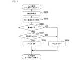
次に、第1バッテリBaの充電前において、スイッチング素子SWa,SWbの故障をチェックする処理手順について、図15を参照して説明する。本処理手順は、充電器5の充電処理のS80において、制御部200により実行される。[3-2. Switching element check process]
Next, a processing procedure for checking the failure of the switching elements SWa and SWb before charging the first battery Ba will be described with reference to FIG. This processing procedure is executed by the
まず、S600では、スイッチング素子SWaをオフ状態に設定する。なお、スイッチング素子SWbはオフ状態に維持されている。
続いて、S610では、メインコンバータ83からスイッチング素子SWaへの電流出力をオンに設定して、メインコンバータ83からスイッチング素子SWaへ電流を流す。First, in S600, the switching element SWa is set to the off state. The switching element SWb is maintained in the off state.
Subsequently, in S610, the current output from the
続いて、S620では、シャント抵抗88を介して取得した電流値に基づいて、第1バッテリBa及び第2バッテリBbの少なくとも一方を流れる充電電流が有るか否か判定する。スイッチング素子SWa,SWbのいずれも短絡していない場合は、第1バッテリBa及び第2バッテリBbのいずれにも充電電流は流れない。一方、スイッチング素子SWa,SWbの少なくとも一方が短絡している場合は、第1バッテリBa及び第2バッテリBbの少なくとも一方に充電電流が流れる。 Subsequently, in S620, based on the current value acquired via the
よって、第1バッテリBa及び第2バッテリBbの少なくとも一方を流れる充電電流が検出された場合には、S650へ進み、エラー判定をして、本処理を終了する。一方、充電電流が検出されなかった場合には、S630へ進む。 Therefore, when the charging current flowing through at least one of the first battery Ba and the second battery Bb is detected, the process proceeds to S650, an error determination is made, and this process is terminated. On the other hand, if the charging current is not detected, the process proceeds to S630.
S630では、分岐点Poよりもメインコンバータ83側の電源電圧の電圧値Vwが25Vを超えているか否か判定する。スイッチング素子SWa,SWbのいずれも短絡していない場合は、電圧値Vwは25Vよりも高くなる。一方、スイッチング素子SWa,SWbの少なくとも一方が短絡している場合は、電圧値Vwが、第1バッテリBaの端子間電圧値である電圧値Va、又は第2バッテリBbの端子間電圧値である電圧値Vbと、略等しい値となる。つまり、一方、スイッチング素子SWa,SWbの少なくとも一方が短絡している場合は、電圧値Vwは25V以下となる。 In S630, it is determined whether or not the voltage value Vw of the power supply voltage on the
よって、電圧値Vwが25Vよりも大きい場合には、S640へ進み、正常判定をして、本処理を終了する。一方、電圧値Vwが25V以下の場合には、S650へ進み、エラー判定をして、本処理を終了する。 Therefore, when the voltage value Vw is larger than 25V, the process proceeds to S640, a normal determination is made, and this processing is terminated. On the other hand, when the voltage value Vw is 25 V or less, the process proceeds to S650, an error determination is made, and this process ends.
また、第2バッテリBbの充電前において、スイッチング素子SWa,SWbの故障をチェックする処理手順を、図16のフローチャートに示す。本処理手順は、充電器5の充電処理のS360において、制御部200により実行される。本処理手順のS700〜S750は、S600〜S650と同様の処理を行う。 Further, a processing procedure for checking the failure of the switching elements SWa and SWb before charging the second battery Bb is shown in the flowchart of FIG. This processing procedure is executed by the
[3−3.モニタ回路のチェック処理]
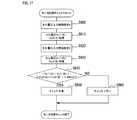
次に、第2バッテリBbの充電前において、モニタ回路125をチェックする処理手順について、図17を参照して説明する。本処理手順は、充電器5の充電処理のS390において、制御部200により実行される。[3-3. Monitor circuit check process]
Next, a processing procedure for checking the
まず、S800では、電圧検出端子100からセル電圧Vc1を入力する経路、及び電圧検出端子110からセル電圧Vc2を入力する経路として、それぞれ経路Aを設定する。 First, in S800, the path A is set as a path for inputting the cell voltage Vc1 from the
続いて、S810では、S800で設定した経路Aからセル電圧Vc1(A)及びセル電圧Vc2(A)を取得する。
続いて、S820では、電圧検出端子100からセル電圧Vc1を入力する経路、及び電圧検出端子110からセル電圧Vc2を入力する経路として、それぞれ経路Bを設定する。Subsequently, in S810, the cell voltage Vc1 (A) and the cell voltage Vc2 (A) are acquired from the path A set in S800.
Subsequently, in S820, the path B is set as a path for inputting the cell voltage Vc1 from the
続いて、S830では、S820で設定した経路Bからセル電圧Vc1(B)及びセル電圧Vc2(B)を取得する。
続いて、|Vc1(A)−Vc1(B)|=ΔVc1、及び|Vc2(A)−Vc2(B)|=ΔVc2が、いずれも300mV未満であるか否か判定する。モニタ回路125が正常であれば、Vc1(A)とVc1(B)は略等しい値となるとともに、Vc2(A)とVc2(B)も略等しい値となる。一方、モニタ回路125が故障していれば、Vc1(A)とVc1(B)が大きく異なる値になったり、Vc2(A)とVc2(B)が大きく異なる値になったりする。Subsequently, in S830, the cell voltage Vc1 (B) and the cell voltage Vc2 (B) are acquired from the path B set in S820.
Subsequently, it is determined whether | Vc1 (A) -Vc1 (B) | = ΔVc1 and | Vc2 (A) -Vc2 (B) | = ΔVc2 are both less than 300 mV. If the
よって、ΔVc1及びΔVc2のいずれも300mV未満の場合、すなわち、Vc1(A)とVc1(B)とが略等しく、且つ、Vc2(A)とVc2(B)とが略等しい場合には、S850へ進み、正常判定をして本処理を終了する。一方、ΔVc1及びΔVc2の少なくとも一方が300mv以上の場合には、S860へ進み、エラー判定をして本処理を終了する。 Therefore, when both ΔVc1 and ΔVc2 are less than 300 mV, that is, when Vc1 (A) and Vc1 (B) are substantially equal and Vc2 (A) and Vc2 (B) are substantially equal, go to S850. Proceed, make a normal judgment, and end this process. On the other hand, when at least one of ΔVc1 and ΔVc2 is 300 mv or more, the process proceeds to S860, an error determination is made, and this process is terminated.
[4.効果]
以上説明した本実施形態によれば、以下の効果が得られる。
(1)充電器5は、異なる装着部11,21に対応した第1接続部31及び第2接続部32を備えている。よって、充電器5に、装着部11を備える第1バッテリBa及び装着部21を備える第2バッテリBbを接続することができる。そして、スイッチング素子SWa,SWbのオン・オフを制御することで、第1バッテリBa及び第2バッテリBbを1つずつ順番に充電することができる。すなわち、1台の充電器5で、第1バッテリBa及び第2バッテリBbを充電することができる。[4. effect]
According to the present embodiment described above, the following effects can be obtained.
(1) The charger 5 includes a
(2)1つのメインコンバータ83で、第1バッテリBa及び第2バッテリBbの両方を充電できる構成となっているため、充電器5を小型化することができる。
(3)充電器5に接続されているバッテリパックが充電対象外となっている場合には、開状態になっているスイッチング素子SWa又はスイッチング素子SWbと、逆流防止部95又は逆流防止部96により、充電対象外のバッテリパックから分岐点Poへの電流の逆流が防止される。よって、スイッチング素子SWa,SWbに加えて逆流防止部95,96も設けたことにより、より安全性を高めることができる。(2) Since one
(3) When the battery pack connected to the charger 5 is not subject to charging, the switching element SWa or the switching element SWb in the open state and the
(4)充電開始前にスイッチング素子SWa,SWbの故障をチェックすることにより、スイッチング素子SWa,SWbのいずれかが故障している場合には、充電を中止することができるため、より安全性を高めることができる。 (4) By checking the failure of the switching elements SWa and SWb before starting charging, if any of the switching elements SWa and SWb is out of order, charging can be stopped, which further improves safety. Can be enhanced.
(5)第1バッテリBaの温度値Ta及び第2バッテリBbの温度値Tbの一方が温度閾値Tthを超えている場合には、当該バッテリパックは温度値が温度閾値Tthよりも低下するまで待機状態にされ、その間に、他のバッテリパックが優先的に充電される。これにより、効率的に複数のバッテリパックを充電することができる。 (5) When one of the temperature value Ta of the first battery Ba and the temperature value Tb of the second battery Bb exceeds the temperature threshold value Tth, the battery pack waits until the temperature value drops below the temperature threshold value Tth. It is put into a state, during which time other battery packs are preferentially charged. As a result, a plurality of battery packs can be efficiently charged.
(6)壁Wに設けられた突起Fに、取り付け部41の嵌合孔42を嵌合させることで、充電器5を壁Wに取り付けて使用することができる。さらに、嵌合孔42が形成された取り付け部41が、ケース50の背面410から突出するように設けられているため、ケース50の背面410に嵌合孔42を形成した場合と比べて、ケース50内への突起Fの侵入を抑制できる。ひいては、ケース50内の空間を有効に利用して、基板45を収納することができる。 (6) By fitting the
(他の実施形態)
以上、本発明を実施するための形態について説明したが、本発明は上述の実施形態に限定されることなく、種々変形して実施することができる。(Other embodiments)
Although the embodiment for carrying out the present invention has been described above, the present invention is not limited to the above-described embodiment and can be implemented in various modifications.
(a)上記実施形態では、第1バッテリBa及び第2バッテリBbの両方を、上から下へスライドさせて第1接続部31及び第2接続部32に装着するが、これに限定されるものではない。例えば、第1接続部31及び第2接続部32の一方又は両方を、上記実施形態とは上下逆向きに充電器5に設け、第1バッテリBa及び第2バッテリBbの一方又は両方を、下から上へスライドさせて、第1接続部31又は第2接続部32に装着する構成にしてもよい。また、第1接続部31及び第2接続部32を、レール部311,312が左右方向に沿うように、充電器5の正面330に設けてもよい。そして、第1バッテリBa及び第2バッテリBbの両方を、左から右へ又は右から左へスライドさせて、第1接続部31及び第2接続部32に装着する構成にしてもよい。あるいは、第1バッテリBa及び第2バッテリBbの一方を左から右へスライドさせ、他方を右から左へスライドさせて、第1接続部31及び第2接続部32に装着する構成にしてもよい。さらに、第1バッテリBa及び第2バッテリBbの一方を上から下または下から上へスライドさせ、他方を左から右または右から左へスライドさせて、第1接続部31及び第2接続部32に装着する構成にしてもよい。 (A) In the above embodiment, both the first battery Ba and the second battery Bb are slid from top to bottom and attached to the
(b)上記実施形態では、第1バッテリBaは内部に制御回路を備え、第2バッテリBbは内部に制御回路を備えていないが、第1バッテリBa及び第2バッテリBbの両方が制御回路を備えていてもよいし、第1バッテリBa及び第2バッテリBbの両方が制御回路を備えていなくてもよい。 (B) In the above embodiment, the first battery Ba has an internal control circuit and the second battery Bb does not have an internal control circuit, but both the first battery Ba and the second battery Bb have a control circuit. It may be provided, or both the first battery Ba and the second battery Bb may not be provided with a control circuit.
(c)上記実施形態では、充電器5は、第1接続部31及び第2接続部32の2つの接続部を備えているが、接続部の数は2つに限定されるものではなく、接続部を3つ以上備えていてもよい。充電器5が、接続部を3つ以上備えている場合は、全て異なる種類の装着部に対応している必要はなく、少なくとも2種類の装着部に対応していればよい。例えば、充電器5が3つの接続部を備えている場合は、同じ種類の装着部に対応した2つの接続部と、他の2つとは異なる種類の装着部に対応した1つの接続部と、を備えていてもよい。 (C) In the above embodiment, the charger 5 includes two connection portions, a
(d)上記実施形態では、充電器5は、取り付け面に取り付けるための取り付け部41を備えているが、取り付け部41を備えていなくてもよい。充電器5が取り付け部41を備えていない場合は、充電器5を台などに置いて使用すればよい。 (D) In the above embodiment, the charger 5 includes a mounting
(e)上記実施形態における1つの構成要素が有する複数の機能を、複数の構成要素によって実現したり、1つの構成要素が有する1つの機能を、複数の構成要素によって実現したりしてもよい。また、複数の構成要素が有する複数の機能を、1つの構成要素によって実現したり、複数の構成要素によって実現される1つの機能を、1つの構成要素によって実現したりしてもよい。また、上記実施形態の構成の一部を省略してもよい。また、上記実施形態の構成の少なくとも一部を、他の上記実施形態の構成に対して付加又は置換してもよい。なお、特許請求の範囲に記載した文言のみによって特定される技術思想に含まれるあらゆる態様が本発明の実施形態である。 (E) A plurality of functions possessed by one component in the above embodiment may be realized by a plurality of components, or one function possessed by one component may be realized by a plurality of components. .. Further, a plurality of functions possessed by the plurality of components may be realized by one component, or one function realized by the plurality of components may be realized by one component. Further, a part of the configuration of the above embodiment may be omitted. In addition, at least a part of the configuration of the above embodiment may be added or replaced with the configuration of the other above embodiment. It should be noted that all aspects included in the technical idea specified only by the wording described in the claims are embodiments of the present invention.
5…充電器、7…ベース部材、11,21…装着部、31…第1接続部、32…第2接続部、38…リブ、39…中継コネクタ、41…取り付け部、42…嵌合孔、45…基板、50…ケース、71,72…絶縁部、83…メインコンバータ、95,96…逆流防止部、120…第2温度入力端子、125…モニタ回路、200…制御部、330…正面、410…背面、451…サブ基板、452…コネクタ、453…絶縁スペーサ、458…シールド基板、Ba…第1バッテリ、Bb…第2バッテリ、Cpa,Cpb…充電経路、F…突起、Po…分岐点、SWa,SWb…スイッチング素子、W…壁。 5 ... Charger, 7 ... Base member, 11,21 ... Mounting part, 31 ... First connection part, 32 ... Second connection part, 38 ... Rib, 39 ... Relay connector, 41 ... Mounting part, 42 ... Fitting hole , 45 ... Board, 50 ... Case, 71, 72 ... Insulation part, 83 ... Main converter, 95, 96 ... Backflow prevention part, 120 ... Second temperature input terminal, 125 ... Monitor circuit, 200 ... Control unit, 330 ... Front , 410 ... back, 451 ... sub-board, 452 ... connector, 453 ... insulating spacer, 458 ... shield board, Ba ... first battery, Bb ... second battery, Cpa, Cpb ... charging path, F ... protrusion, Po ... branch Point, SWa, SWb ... Switching element, W ... Wall.
Claims (7)
Translated fromJapanese前記第1の定格電圧よりも小さい第2の定格電圧を有するスライド式の第2のバッテリの第2の装着部であって、前記第1の装着部と形状が異なる第2の装着部が装着されるように構成された第2の接続部と、
入力電力から充電電力を生成する1つの電源回路と、
前記電源回路と前記第1の接続部とを接続する第1の充電経路と、
前記電源回路と前記第2の接続部とを接続する第2の充電経路と、
前記第1の充電経路に設けられ、閉状態にて前記第1の充電経路を接続状態にし、開状態にて前記第1の充電経路を切断状態にするように構成された第1の開閉部と、
前記第2の充電経路に設けられ、閉状態にて前記第2の充電経路を接続状態にし、開状態にて前記第2の充電経路を切断状態にするように構成された第2の開閉部と、
前記第1の接続部に接続されている前記第1のバッテリ又は前記第2の接続部に接続されている前記第2のバッテリを充電対象とし、前記第1の開閉部及び前記第2の開閉部のうち、前記充電対象が前記第1の接続部又は前記第2の接続部を介して接続されている前記第1の充電経路又は前記第2の充電経路に設けられた開閉部を前記閉状態にして、前記充電対象に適した充電電流で予め決められた電圧まで前記充電対象を充電するように構成された充電制御部と、
前記第1の接続部に装着された前記第1のバッテリを冷却するための第1のファンと、
前記第2の接続部に装着された前記第2のバッテリを冷却するための第2のファンと、
前記電源回路と、前記第1の充電経路と、前記第2の充電経路と、前記第1の開閉部と、前記第2の開閉部と、前記充電制御部と、前記第1のファンと、前記第2のファンと、を収納し、1つの面に前記第1の接続部及び前記第2の接続部が設けられたケースと、
前記第1の接続部において、前記第1のファンに対応する位置に設けられた第1の送風開口と、
前記第2の接続部において、前記第2のファンに対応する位置に設けられた第2の送風開口と、を備え、
前記第2の送風開口は、前記第1の送風開口よりも小さく構成されている、
充電器。Afirst connecting portionwhere the first mounting portion of the sliding first battery having a first rated voltage is configured to bemounted
A second mounting portion of a slide-type second battery having a second rated voltage smaller than the first rated voltage and having a shape different from that of the first mounting portion is mounted. A second connection configured to be
One power supply circuit that generates charging power from input power,
A first charging path connecting the power supply circuit andthe first connection portion,
A second charging path connecting the power supply circuit and the second connection portion,
Provided in thefirst charging path, and thefirst charging path in the closed state to the connected state,the first closing portion configured thefirst charging path in opened state to a disconnected state When,
A second opening / closing unit provided in the second charging path and configured to connect the second charging path in the closed state and disconnect the second charging path in the open state. When,
Saidsecond battery connected tothe first battery or the second connecting portion connected to thefirst connecting portion and the charging target, thefirst closing portionand the second opening and closing Among the units , the opening / closing portion provided inthe first charging pathor the second charging path to which the charging target is connected viathe firstconnecting portion or the second connecting portion is closed. A charging control unit configured to be in a state and to charge the charging target to a predetermined voltage with a charging current suitable for the charging target.
A first fan for cooling the first battery mounted on the first connection portion, and
A second fan for cooling the second battery mounted on the second connection portion, and
The power supply circuit, the first charging path, the second charging path, the first opening / closing section, the second opening / closing section, the charging control section, the first fan, and the like. A case in which the second fan is housed, and the first connection portion and the second connection portion are provided on one surface.
In the first connection portion, a first blower opening provided at a position corresponding to the first fan, and
The second connection portion includes a second blower opening provided at a position corresponding to the second fan.
The second blower opening is smaller than the first blower opening.
Charger.
前記分岐点と前記第2の接続部との間に設けられ、前記第2の接続部の側から前記分岐点への電流の逆流を防止するように構成された第2の逆流防止部と、を備える、請求項1に記載の充電器。A branch point at whichthe first charging pathand the second charging pathbranch toward each of the first opening / closing portionand the second opening / closing portion is provided betweenthe first opening / closing portion and the first connecting portion. , Afirst backflow prevention unit configured to prevent backflow of current from the side ofthe firstconnection part to thebranch point.
A second backflow prevention unit provided between the branch point and the second connection part and configured to prevent a backflow of current from the side of the second connection part to the branch point. The charger according to claim 1.
前記取り付け部には、前記充電器が取り付けられる取り付け面に設けられた突起に嵌合させる嵌合孔が形成されている、請求項1〜4のいずれか1項に記載の充電器。The case comprises at least one mounting portion provided so as to project from a surface different from the one surface.
The charger according to any one of claims 1 to 4, wherein the mounting portion is formed with a fitting hole for fitting into a protrusion provided on a mounting surface on which the charger is mounted.
前記第1のバッテリは、前記スライド方向に垂直な方向に延伸した第1の嵌合爪を備え、The first battery comprises a first fitting claw that extends in a direction perpendicular to the sliding direction.
前記第2のバッテリは、前記スライド方向に垂直な方向に延伸した第2の嵌合爪を備え、The second battery comprises a second fitting claw that extends in a direction perpendicular to the sliding direction.
前記第1の接続部は、前記スライド方向に垂直な方向に延伸し、前記第1の嵌合爪と嵌合する第1の嵌合溝を備え、The first connecting portion includes a first fitting groove that extends in a direction perpendicular to the sliding direction and fits with the first fitting claw.
前記第2の接続部は、前記スライド方向に垂直な方向に延伸し、前記第2の嵌合爪と嵌合する第2の嵌合溝を備え、The second connecting portion includes a second fitting groove that extends in a direction perpendicular to the sliding direction and fits with the second fitting claw.
前記第1の嵌合溝は、前記スライド方向において、前記第2の嵌合溝と略同じ位置に設けられており、前記第1の嵌合溝は、前記第2の嵌合溝と異なる形状に構成されている、The first fitting groove is provided at substantially the same position as the second fitting groove in the slide direction, and the first fitting groove has a shape different from that of the second fitting groove. Is composed of
請求項1〜5のいずれか1項に記載の充電器。The charger according to any one of claims 1 to 5.
前記第2の接続部は、前記第2の装着部におけるスライドレールにスライドして嵌合するように構成された1組のレールを有する第2のレール部を備え、The second connecting portion comprises a second rail portion having a set of rails configured to slide and fit on the slide rail in the second mounting portion.
前記第1のレール部は、前記第2のレール部に平行に設けられ、前記第1のレール部の前記1組のレールの間隔は、前記第2のレール部の前記1組のレールの間隔よりも広く構成されている、The first rail portion is provided in parallel with the second rail portion, and the distance between the set of rails in the first rail portion is the distance between the set of rails in the second rail portion. Wider than
請求項1〜6のいずれか1項に記載の充電器。The charger according to any one of claims 1 to 6.
Priority Applications (4)
| Application Number | Priority Date | Filing Date | Title |
|---|---|---|---|
| JP2017057517AJP6898122B2 (en) | 2017-03-23 | 2017-03-23 | Charger |
| US15/920,888US10483776B2 (en) | 2017-03-23 | 2018-03-14 | Charger |
| CN201820349122.5UCN208190275U (en) | 2017-03-23 | 2018-03-14 | Charger |
| EP18163654.9AEP3379688A1 (en) | 2017-03-23 | 2018-03-23 | Charger |
Applications Claiming Priority (1)
| Application Number | Priority Date | Filing Date | Title |
|---|---|---|---|
| JP2017057517AJP6898122B2 (en) | 2017-03-23 | 2017-03-23 | Charger |
Publications (2)
| Publication Number | Publication Date |
|---|---|
| JP2018160997A JP2018160997A (en) | 2018-10-11 |
| JP6898122B2true JP6898122B2 (en) | 2021-07-07 |
Family
ID=61763896
Family Applications (1)
| Application Number | Title | Priority Date | Filing Date |
|---|---|---|---|
| JP2017057517AActiveJP6898122B2 (en) | 2017-03-23 | 2017-03-23 | Charger |
Country Status (4)
| Country | Link |
|---|---|
| US (1) | US10483776B2 (en) |
| EP (1) | EP3379688A1 (en) |
| JP (1) | JP6898122B2 (en) |
| CN (1) | CN208190275U (en) |
Families Citing this family (29)
| Publication number | Priority date | Publication date | Assignee | Title |
|---|---|---|---|---|
| JP6470804B1 (en)* | 2017-08-31 | 2019-02-13 | 株式会社ソフトエナジーコントロールズ | Multi-channel charge / discharge power supply with contact function |
| TWD193390S (en)* | 2018-02-05 | 2018-10-11 | 林鈺堂 | Charger |
| US11264818B2 (en)* | 2018-07-04 | 2022-03-01 | Techtronic Cordless Gp | Battery charger for multiple battery packs |
| AU2019314293B2 (en) | 2018-07-30 | 2022-06-02 | Milwaukee Electric Tool Corporation | Battery charger |
| CN210120406U (en) | 2018-10-17 | 2020-02-28 | 米沃奇电动工具公司 | Battery charger |
| JP7123778B2 (en)* | 2018-12-10 | 2022-08-23 | 株式会社マキタ | battery pack charger |
| CN120675245A (en)* | 2019-03-01 | 2025-09-19 | 康曼德公司 | Sterile battery charging |
| USD914099S1 (en)* | 2019-06-07 | 2021-03-23 | The AbleGamers Foundation, Inc. | Flush mounted game controller holster |
| JP1653810S (en) | 2019-07-30 | 2020-02-25 | ||
| USD1012855S1 (en) | 2019-09-05 | 2024-01-30 | Techtronic Cordless Gp | Battery pack |
| USD953268S1 (en)* | 2019-09-05 | 2022-05-31 | Techtronic Cordless Gp | Electrical interface |
| JP7350576B2 (en)* | 2019-09-09 | 2023-09-26 | 株式会社マキタ | charger |
| USD879713S1 (en)* | 2019-12-02 | 2020-03-31 | Pioneer Square Brands, Inc. | Charging station for portable electronic computing devices |
| US11996719B2 (en) | 2020-03-27 | 2024-05-28 | Milwaukee Electric Tool Corporation | Modular storage unit with charger for power tool battery packs |
| US11755088B2 (en)* | 2020-05-04 | 2023-09-12 | Dell Products L.P. | System and method for dynamic switching between batteries in a dual battery system |
| JP7477405B2 (en)* | 2020-09-14 | 2024-05-01 | 株式会社マキタ | Charger |
| JP1684889S (en)* | 2020-10-07 | 2021-05-10 | ||
| DE102021203224A1 (en)* | 2021-03-30 | 2022-10-06 | Robert Bosch Gesellschaft mit beschränkter Haftung | Charging device for a battery pack |
| EP4340166B1 (en)* | 2021-07-27 | 2025-10-15 | Samsung Electronics Co., Ltd. | Electronic apparatus for charging another electronic apparatus, and method for controlling electronic apparatus for charging other electronic apparatus |
| USD1034443S1 (en)* | 2021-10-20 | 2024-07-09 | Globe (jiangsu) Co., Ltd. | Charger |
| USD977481S1 (en) | 2022-11-07 | 2023-02-07 | Pioneer Square Brands, Inc. | Station for portable electronic computing devices |
| JP1746632S (en)* | 2022-11-28 | 2023-06-19 | charger | |
| USD1055849S1 (en)* | 2022-11-28 | 2024-12-31 | Makita Corporation | Battery charger |
| USD1023945S1 (en) | 2023-04-04 | 2024-04-23 | Pioneer Square Brands, Inc. | Charging station for portable electronic devices |
| USD1008171S1 (en) | 2023-06-20 | 2023-12-19 | Pioneer Square Brands, Inc. | Charging station for portable electronic devices |
| USD1006729S1 (en)* | 2023-08-07 | 2023-12-05 | Pioneer Square Brands, Inc. | Charger for portable electronic device |
| WO2025070049A1 (en)* | 2023-09-28 | 2025-04-03 | 工機ホールディングス株式会社 | Charging device |
| USD1020629S1 (en) | 2023-11-10 | 2024-04-02 | Pioneer Square Brands, Inc. | Portable electronic device charger |
| USD1037146S1 (en) | 2024-03-21 | 2024-07-30 | Pioneer Square Brands, Inc. | Charging station for portable electronic devices |
Family Cites Families (12)
| Publication number | Priority date | Publication date | Assignee | Title |
|---|---|---|---|---|
| JPH06113471A (en)* | 1992-09-29 | 1994-04-22 | Sanyo Electric Co Ltd | Battery charger |
| JPH1075539A (en)* | 1996-08-30 | 1998-03-17 | Sanyo Electric Co Ltd | Charging device |
| US6204632B1 (en)* | 1999-09-08 | 2001-03-20 | Selfcharge | Apparatus for charging multiple batteries |
| CA2411303A1 (en)* | 2001-11-09 | 2003-05-09 | Milwaukee Electric Tool Corporation | Battery charger |
| JP2012090474A (en)* | 2010-10-21 | 2012-05-10 | Hitachi Vehicle Energy Ltd | Battery system |
| US9077053B2 (en)* | 2011-07-20 | 2015-07-07 | Milwaukee Electric Tool Corporation | Battery charger including multiple charging ports on surfaces forming an apex |
| KR101410000B1 (en) | 2012-05-16 | 2014-07-02 | 엘지전자 주식회사 | Energy storage device and method for controlling the same |
| JP6067341B2 (en)* | 2012-11-15 | 2017-01-25 | 三洋電機株式会社 | Charger |
| US20140266048A1 (en)* | 2013-03-15 | 2014-09-18 | Black & Decker Inc. | Dual Port Charger |
| JP5652562B1 (en)* | 2013-09-19 | 2015-01-14 | 株式会社豊田自動織機 | MOSFET switch element abnormality diagnosis apparatus and method |
| JP6177709B2 (en)* | 2014-02-26 | 2017-08-09 | 株式会社マキタ | Charger |
| DE102015002072B4 (en) | 2015-02-18 | 2024-11-07 | Audi Ag | Setting the charge states of battery cells |
- 2017
- 2017-03-23JPJP2017057517Apatent/JP6898122B2/enactiveActive
- 2018
- 2018-03-14CNCN201820349122.5Upatent/CN208190275U/enactiveActive
- 2018-03-14USUS15/920,888patent/US10483776B2/enactiveActive
- 2018-03-23EPEP18163654.9Apatent/EP3379688A1/ennot_activeWithdrawn
Also Published As
| Publication number | Publication date |
|---|---|
| US10483776B2 (en) | 2019-11-19 |
| JP2018160997A (en) | 2018-10-11 |
| EP3379688A1 (en) | 2018-09-26 |
| CN208190275U (en) | 2018-12-04 |
| US20180278071A1 (en) | 2018-09-27 |
Similar Documents
| Publication | Publication Date | Title |
|---|---|---|
| JP6898122B2 (en) | Charger | |
| US10547186B2 (en) | Charging apparatus | |
| US9341681B2 (en) | Electrical device system and battery pack | |
| CN101051760B (en) | Battery pack and electronic equipment using the battery pack | |
| JPWO2019022072A1 (en) | Battery pack and electrical equipment using battery pack | |
| US20160072320A1 (en) | Overcurrent detection device, and charging/discharging system, distribution board, charging control device, charging/discharging device for vehicle and electrical apparatus for vehicle, using the overcurrent detection device | |
| JP4232990B1 (en) | Battery pack | |
| US9853463B2 (en) | Battery monitoring and control integrated circuit and battery system | |
| US20100308775A1 (en) | Battery pack and secondary battery system | |
| US20140001853A1 (en) | Charger and power supply system | |
| JP2015082931A (en) | Charging adapter and power supply system including the same | |
| JP2010200561A (en) | Charging equipment | |
| CN104701920A (en) | Portable DC power supply | |
| KR100788595B1 (en) | Portable auxiliary power supply | |
| US11979039B2 (en) | Charging device having two charging modes | |
| JP2019193498A (en) | Electrical machine | |
| JP7110798B2 (en) | charging device | |
| US20230216430A1 (en) | Electrical storage device | |
| US20200044479A1 (en) | Power strip with uninterruptable power supply | |
| JP2017077084A (en) | Storage battery device and storage battery system | |
| JP7072479B2 (en) | Battery pack | |
| JP2014014273A (en) | Semiconductor unit and power conversion apparatus | |
| WO2010074351A2 (en) | Charging device | |
| JP2022107172A (en) | Adapter and charging system | |
| KR20140125663A (en) | Communication system combined with ups and method thereof |
Legal Events
| Date | Code | Title | Description |
|---|---|---|---|
| A621 | Written request for application examination | Free format text:JAPANESE INTERMEDIATE CODE: A621 Effective date:20191219 | |
| A977 | Report on retrieval | Free format text:JAPANESE INTERMEDIATE CODE: A971007 Effective date:20201022 | |
| A131 | Notification of reasons for refusal | Free format text:JAPANESE INTERMEDIATE CODE: A131 Effective date:20201027 | |
| A521 | Request for written amendment filed | Free format text:JAPANESE INTERMEDIATE CODE: A523 Effective date:20201223 | |
| TRDD | Decision of grant or rejection written | ||
| A01 | Written decision to grant a patent or to grant a registration (utility model) | Free format text:JAPANESE INTERMEDIATE CODE: A01 Effective date:20210525 | |
| A61 | First payment of annual fees (during grant procedure) | Free format text:JAPANESE INTERMEDIATE CODE: A61 Effective date:20210610 | |
| R150 | Certificate of patent or registration of utility model | Ref document number:6898122 Country of ref document:JP Free format text:JAPANESE INTERMEDIATE CODE: R150 | |
| R250 | Receipt of annual fees | Free format text:JAPANESE INTERMEDIATE CODE: R250 | |
| R250 | Receipt of annual fees | Free format text:JAPANESE INTERMEDIATE CODE: R250 |