JP6897098B2 - Printing fluid cartridges, printing fluid cartridge sets, and systems - Google Patents
Printing fluid cartridges, printing fluid cartridge sets, and systemsDownload PDFInfo
- Publication number
- JP6897098B2 JP6897098B2JP2016256032AJP2016256032AJP6897098B2JP 6897098 B2JP6897098 B2JP 6897098B2JP 2016256032 AJP2016256032 AJP 2016256032AJP 2016256032 AJP2016256032 AJP 2016256032AJP 6897098 B2JP6897098 B2JP 6897098B2
- Authority
- JP
- Japan
- Prior art keywords
- printing fluid
- cartridge
- fluid cartridge
- ink
- light
- Prior art date
- Legal status (The legal status is an assumption and is not a legal conclusion. Google has not performed a legal analysis and makes no representation as to the accuracy of the status listed.)
- Active
Links
- 239000012530fluidSubstances0.000titleclaimsdescription137
- 238000003780insertionMethods0.000claimsdescription109
- 230000037431insertionEffects0.000claimsdescription109
- 238000003860storageMethods0.000claimsdescription61
- 230000003287optical effectEffects0.000claimsdescription39
- 238000000034methodMethods0.000claimsdescription19
- 230000008569processEffects0.000claimsdescription17
- 238000000638solvent extractionMethods0.000claimsdescription8
- 230000004044responseEffects0.000claimsdescription6
- 239000000976inkSubstances0.000description399
- 239000000758substrateSubstances0.000description35
- 238000004891communicationMethods0.000description26
- 238000012856packingMethods0.000description16
- 238000005192partitionMethods0.000description11
- 230000002093peripheral effectEffects0.000description5
- 239000011347resinSubstances0.000description5
- 229920005989resinPolymers0.000description5
- 238000007789sealingMethods0.000description4
- 230000004888barrier functionEffects0.000description3
- 230000008859changeEffects0.000description3
- 239000000463materialSubstances0.000description3
- 238000001514detection methodMethods0.000description2
- 229920001971elastomerPolymers0.000description2
- 230000005484gravityEffects0.000description2
- 239000007788liquidSubstances0.000description2
- 238000004519manufacturing processMethods0.000description2
- 230000009471actionEffects0.000description1
- 229910052782aluminiumInorganic materials0.000description1
- XAGFODPZIPBFFR-UHFFFAOYSA-NaluminiumChemical compound[Al]XAGFODPZIPBFFR-UHFFFAOYSA-N0.000description1
- 238000013459approachMethods0.000description1
- 238000004140cleaningMethods0.000description1
- 239000003086colorantSubstances0.000description1
- 230000000694effectsEffects0.000description1
- 230000005489elastic deformationEffects0.000description1
- 239000013013elastic materialSubstances0.000description1
- 239000000806elastomerSubstances0.000description1
- 239000011888foilSubstances0.000description1
- 230000006870functionEffects0.000description1
- 229910052751metalInorganic materials0.000description1
- 239000002184metalSubstances0.000description1
- 239000000203mixtureSubstances0.000description1
- 230000004048modificationEffects0.000description1
- 238000012986modificationMethods0.000description1
- 230000000149penetrating effectEffects0.000description1
- 239000000049pigmentSubstances0.000description1
- 239000000843powderSubstances0.000description1
- 238000003825pressingMethods0.000description1
- 238000010926purgeMethods0.000description1
- 239000011435rockSubstances0.000description1
- 239000004065semiconductorSubstances0.000description1
- 229910052710siliconInorganic materials0.000description1
- 239000010703siliconSubstances0.000description1
- 230000001960triggered effectEffects0.000description1
- XLYOFNOQVPJJNP-UHFFFAOYSA-NwaterSubstancesOXLYOFNOQVPJJNP-UHFFFAOYSA-N0.000description1
Images


Classifications
- B—PERFORMING OPERATIONS; TRANSPORTING
- B41—PRINTING; LINING MACHINES; TYPEWRITERS; STAMPS
- B41J—TYPEWRITERS; SELECTIVE PRINTING MECHANISMS, i.e. MECHANISMS PRINTING OTHERWISE THAN FROM A FORME; CORRECTION OF TYPOGRAPHICAL ERRORS
- B41J2/00—Typewriters or selective printing mechanisms characterised by the printing or marking process for which they are designed
- B41J2/005—Typewriters or selective printing mechanisms characterised by the printing or marking process for which they are designed characterised by bringing liquid or particles selectively into contact with a printing material
- B41J2/01—Ink jet
- B41J2/17—Ink jet characterised by ink handling
- B41J2/175—Ink supply systems ; Circuit parts therefor
- B41J2/17503—Ink cartridges
- B41J2/1752—Mounting within the printer
- B—PERFORMING OPERATIONS; TRANSPORTING
- B41—PRINTING; LINING MACHINES; TYPEWRITERS; STAMPS
- B41J—TYPEWRITERS; SELECTIVE PRINTING MECHANISMS, i.e. MECHANISMS PRINTING OTHERWISE THAN FROM A FORME; CORRECTION OF TYPOGRAPHICAL ERRORS
- B41J2/00—Typewriters or selective printing mechanisms characterised by the printing or marking process for which they are designed
- B41J2/005—Typewriters or selective printing mechanisms characterised by the printing or marking process for which they are designed characterised by bringing liquid or particles selectively into contact with a printing material
- B41J2/01—Ink jet
- B41J2/17—Ink jet characterised by ink handling
- B41J2/175—Ink supply systems ; Circuit parts therefor
- B41J2/17503—Ink cartridges
- B41J2/17506—Refilling of the cartridge
- B41J2/17509—Whilst mounted in the printer
- B—PERFORMING OPERATIONS; TRANSPORTING
- B41—PRINTING; LINING MACHINES; TYPEWRITERS; STAMPS
- B41J—TYPEWRITERS; SELECTIVE PRINTING MECHANISMS, i.e. MECHANISMS PRINTING OTHERWISE THAN FROM A FORME; CORRECTION OF TYPOGRAPHICAL ERRORS
- B41J2/00—Typewriters or selective printing mechanisms characterised by the printing or marking process for which they are designed
- B41J2/005—Typewriters or selective printing mechanisms characterised by the printing or marking process for which they are designed characterised by bringing liquid or particles selectively into contact with a printing material
- B41J2/01—Ink jet
- B41J2/17—Ink jet characterised by ink handling
- B41J2/175—Ink supply systems ; Circuit parts therefor
- B41J2/17503—Ink cartridges
- B41J2/17513—Inner structure
- B—PERFORMING OPERATIONS; TRANSPORTING
- B41—PRINTING; LINING MACHINES; TYPEWRITERS; STAMPS
- B41J—TYPEWRITERS; SELECTIVE PRINTING MECHANISMS, i.e. MECHANISMS PRINTING OTHERWISE THAN FROM A FORME; CORRECTION OF TYPOGRAPHICAL ERRORS
- B41J2/00—Typewriters or selective printing mechanisms characterised by the printing or marking process for which they are designed
- B41J2/005—Typewriters or selective printing mechanisms characterised by the printing or marking process for which they are designed characterised by bringing liquid or particles selectively into contact with a printing material
- B41J2/01—Ink jet
- B41J2/17—Ink jet characterised by ink handling
- B41J2/175—Ink supply systems ; Circuit parts therefor
- B41J2/17503—Ink cartridges
- B41J2/1752—Mounting within the printer
- B41J2/17523—Ink connection
- B—PERFORMING OPERATIONS; TRANSPORTING
- B41—PRINTING; LINING MACHINES; TYPEWRITERS; STAMPS
- B41J—TYPEWRITERS; SELECTIVE PRINTING MECHANISMS, i.e. MECHANISMS PRINTING OTHERWISE THAN FROM A FORME; CORRECTION OF TYPOGRAPHICAL ERRORS
- B41J2/00—Typewriters or selective printing mechanisms characterised by the printing or marking process for which they are designed
- B41J2/005—Typewriters or selective printing mechanisms characterised by the printing or marking process for which they are designed characterised by bringing liquid or particles selectively into contact with a printing material
- B41J2/01—Ink jet
- B41J2/17—Ink jet characterised by ink handling
- B41J2/175—Ink supply systems ; Circuit parts therefor
- B41J2/17503—Ink cartridges
- B41J2/17526—Electrical contacts to the cartridge
- B41J2/1753—Details of contacts on the cartridge, e.g. protection of contacts
- B—PERFORMING OPERATIONS; TRANSPORTING
- B41—PRINTING; LINING MACHINES; TYPEWRITERS; STAMPS
- B41J—TYPEWRITERS; SELECTIVE PRINTING MECHANISMS, i.e. MECHANISMS PRINTING OTHERWISE THAN FROM A FORME; CORRECTION OF TYPOGRAPHICAL ERRORS
- B41J2/00—Typewriters or selective printing mechanisms characterised by the printing or marking process for which they are designed
- B41J2/005—Typewriters or selective printing mechanisms characterised by the printing or marking process for which they are designed characterised by bringing liquid or particles selectively into contact with a printing material
- B41J2/01—Ink jet
- B41J2/17—Ink jet characterised by ink handling
- B41J2/175—Ink supply systems ; Circuit parts therefor
- B41J2/17503—Ink cartridges
- B41J2/17543—Cartridge presence detection or type identification
- B41J2/17546—Cartridge presence detection or type identification electronically
- B—PERFORMING OPERATIONS; TRANSPORTING
- B41—PRINTING; LINING MACHINES; TYPEWRITERS; STAMPS
- B41J—TYPEWRITERS; SELECTIVE PRINTING MECHANISMS, i.e. MECHANISMS PRINTING OTHERWISE THAN FROM A FORME; CORRECTION OF TYPOGRAPHICAL ERRORS
- B41J2/00—Typewriters or selective printing mechanisms characterised by the printing or marking process for which they are designed
- B41J2/005—Typewriters or selective printing mechanisms characterised by the printing or marking process for which they are designed characterised by bringing liquid or particles selectively into contact with a printing material
- B41J2/01—Ink jet
- B41J2/17—Ink jet characterised by ink handling
- B41J2/175—Ink supply systems ; Circuit parts therefor
- B41J2/17503—Ink cartridges
- B41J2/17553—Outer structure
- B—PERFORMING OPERATIONS; TRANSPORTING
- B41—PRINTING; LINING MACHINES; TYPEWRITERS; STAMPS
- B41J—TYPEWRITERS; SELECTIVE PRINTING MECHANISMS, i.e. MECHANISMS PRINTING OTHERWISE THAN FROM A FORME; CORRECTION OF TYPOGRAPHICAL ERRORS
- B41J2/00—Typewriters or selective printing mechanisms characterised by the printing or marking process for which they are designed
- B41J2/005—Typewriters or selective printing mechanisms characterised by the printing or marking process for which they are designed characterised by bringing liquid or particles selectively into contact with a printing material
- B41J2/01—Ink jet
- B41J2/17—Ink jet characterised by ink handling
- B41J2/175—Ink supply systems ; Circuit parts therefor
- B41J2/17566—Ink level or ink residue control
- B—PERFORMING OPERATIONS; TRANSPORTING
- B41—PRINTING; LINING MACHINES; TYPEWRITERS; STAMPS
- B41J—TYPEWRITERS; SELECTIVE PRINTING MECHANISMS, i.e. MECHANISMS PRINTING OTHERWISE THAN FROM A FORME; CORRECTION OF TYPOGRAPHICAL ERRORS
- B41J29/00—Details of, or accessories for, typewriters or selective printing mechanisms not otherwise provided for
- B41J29/12—Guards, shields or dust excluders
- B41J29/13—Cases or covers
- B—PERFORMING OPERATIONS; TRANSPORTING
- B41—PRINTING; LINING MACHINES; TYPEWRITERS; STAMPS
- B41J—TYPEWRITERS; SELECTIVE PRINTING MECHANISMS, i.e. MECHANISMS PRINTING OTHERWISE THAN FROM A FORME; CORRECTION OF TYPOGRAPHICAL ERRORS
- B41J2/00—Typewriters or selective printing mechanisms characterised by the printing or marking process for which they are designed
- B41J2/005—Typewriters or selective printing mechanisms characterised by the printing or marking process for which they are designed characterised by bringing liquid or particles selectively into contact with a printing material
- B41J2/01—Ink jet
- B41J2/17—Ink jet characterised by ink handling
- B41J2/175—Ink supply systems ; Circuit parts therefor
- B41J2/17566—Ink level or ink residue control
- B41J2002/17573—Ink level or ink residue control using optical means for ink level indication
Landscapes
- Ink Jet (AREA)
Description
Translated fromJapanese本発明は、印刷流体カートリッジ、印刷流体カートリッジセット、及び当該印刷流体カートリッジが装着される印刷流体供給装置を有するシステムに関する。 The present invention relates to a system having a printing fluid cartridge, a printing fluid cartridge set, and a printing fluid supply device to which the printing fluid cartridge is mounted.
従来より、インク容器に貯留されたインクをノズルから吐出することによって、記録媒体に画像を記録するインクジェット記録装置が知られている。インクジェット記録装置において、インクが消費される毎に新たなインクカートリッジを装着可能に構成されたものがある。カラー印刷が可能なインクジェット記録装置では、複数のインクカートリッジが装着可能である。 Conventionally, an inkjet recording device that records an image on a recording medium by ejecting ink stored in an ink container from a nozzle has been known. Some inkjet recording devices are configured so that a new ink cartridge can be installed each time the ink is consumed. In an inkjet recording device capable of color printing, a plurality of ink cartridges can be mounted.
例えば、特許文献1には、インクカートリッジに収容されたインクに関する情報を記憶する情報記憶部が設けられた構成が開示されている。インクに関する情報は、例えば、製造年月日や型番、インク残量などである。インクカートリッジがインクジェット記録装置に装着されると、情報記憶部が接続端子と電気的に接触して、情報記憶部が記憶するインクに関する情報が読み出し可能となる。 For example, Patent Document 1 discloses a configuration in which an information storage unit for storing information about ink contained in an ink cartridge is provided. The information about the ink is, for example, the date of manufacture, the model number, the remaining amount of ink, and the like. When the ink cartridge is attached to the inkjet recording device, the information storage unit electrically contacts the connection terminal, and the information about the ink stored in the information storage unit can be read out.
インクには、例えば色や成分などの種別がある。前述されたように、複数のインクカートリッジが装着可能なインクジェット記録装置において、ユーザが位置を誤ってインクカートリッジを装着しようとするおそれがある。例えば、イエローのインクが貯留されたインクカートリッジが装着されるべき位置に、ブラックのインクが貯留されたインクカートリッジが誤って挿入されることが想定される。情報記憶部にインクの色などが記憶されていれば、誤って装着されたインクカートリッジの情報記憶部からインクに関する情報が読み出されることにより、誤った位置にインクカートリッジが装着されていることを判定できる。 Inks include types such as colors and components. As described above, in an inkjet recording device in which a plurality of ink cartridges can be mounted, there is a risk that the user attempts to mount the ink cartridges at the wrong position. For example, it is assumed that the ink cartridge containing the black ink is erroneously inserted at the position where the ink cartridge containing the yellow ink should be installed. If the color of the ink is stored in the information storage unit, it is determined that the ink cartridge is installed in the wrong position by reading the information about the ink from the information storage unit of the ink cartridge that was installed incorrectly. it can.
しかし、ブラックのインクを貯留するインクカートリッジが、本来イエローのインクを貯留するインクカートリッジが装着されるべき位置に装着されると、インクカートリッジからブラックのインクが流出して、インクジェット画像記録装置の接続部などに存在するイエローのインクと混色する。このような混色を解消するには、インクジェット記録装置において、大量のパージなどを実行する必要があり、インクが大量に消費される。このような混色の問題を回避するために、誤ったインクカートリッジが接続部に接続されないように、正式な位置に設けられた凹凸形状などに対応するキー形状が、インクカートリッジに設けられることが考えられる。キー形状が合致していなければ、インクカートリッジが接続部と接続されないので、混色が生じることがない。 However, when the ink cartridge that stores black ink is installed at the position where the ink cartridge that originally stores yellow ink should be installed, the black ink flows out from the ink cartridge and the inkjet image recording device is connected. It mixes with the yellow ink that exists in the parts. In order to eliminate such color mixing, it is necessary to perform a large amount of purging or the like in the inkjet recording apparatus, and a large amount of ink is consumed. In order to avoid such a problem of color mixing, it is conceivable that the ink cartridge is provided with a key shape corresponding to the uneven shape provided at the formal position so that the wrong ink cartridge is not connected to the connection portion. Be done. If the key shapes do not match, the ink cartridge will not be connected to the connection, and color mixing will not occur.
しかし、インクカートリッジが装着される過程において、正式な位置に設けられた凹凸形状が情報記憶部と接触すると、情報記憶部の電極などが傷つけられ、最悪な場合には情報記憶部からの情報の読み出しが不可能になるおそれがある。 However, in the process of mounting the ink cartridge, if the uneven shape provided at the formal position comes into contact with the information storage unit, the electrodes of the information storage unit may be damaged, and in the worst case, the information from the information storage unit may be damaged. Reading may become impossible.
本発明は、前述された事情に鑑みてなされたものであり、その目的は、キー形状(干渉面)に対応するカートリッジ装着部の凸部が、電気的インターフェースと接触しにくい印刷流体カートリッジを提供することにある。 The present invention has been made in view of the above-mentioned circumstances, and an object of the present invention is to provide a printing fluid cartridge in which a convex portion of a cartridge mounting portion corresponding to a key shape (interference surface) does not easily come into contact with an electrical interface. To do.
(1) 本発明は、カートリッジ装着部が有する複数の挿入空間のうち既定の挿入空間へ挿入方向に挿入されることによって当該カートリッジ装着部に装着される印刷流体カートリッジに関する。印刷流体カートリッジは、印刷流体が貯留される貯留室を有する筐体と、上記挿入方向の前方に開口を有しており、上記貯留室から印刷流体を外部へ流出する供給部と、上記筐体において上方を向くように設けられた電気的インターフェースと、上記貯留室の上方において上記電気的インターフェースより上記挿入方向の前方、且つ下方に配置されて上記挿入方向と交差する方向へ延びており、上記カートリッジ装着部の既定と異なる挿入空間へ挿入される過程において、当該挿入空間の凸部と当接する干渉面と、を具備する。 (1) The present invention relates to a printing fluid cartridge mounted on the cartridge mounting portion by being inserted into a predetermined insertion space among a plurality of insertion spaces of the cartridge mounting portion in the insertion direction. The printing fluid cartridge has a housing having a storage chamber for storing the printing fluid, a supply unit having an opening in front of the insertion direction and allowing the printing fluid to flow out from the storage chamber, and the housing. And an electrical interface provided so as to face upward in the above, and above the storage chamber, the electrical interface is arranged in front of and below the insertion direction and extends in a direction intersecting the insertion direction. In the process of being inserted into an insertion space different from the default of the cartridge mounting portion, an interference surface that comes into contact with the convex portion of the insertion space is provided.
干渉面が電気的インターフェースより挿入方向の前方且つ下方に配置されているので、カートリッジ装着部の挿入空間に印刷流体カートリッジが挿入される過程において、干渉面に対応する凸部が電気的インターフェースに接触するおそれが軽減される。 Since the interference surface is arranged forward and below the insertion direction from the electrical interface, the convex portion corresponding to the interference surface comes into contact with the electrical interface in the process of inserting the printing fluid cartridge into the insertion space of the cartridge mounting portion. The risk of doing so is reduced.
(2) 好ましくは、上記干渉面は、上記貯留室の前端を画定する内前面より後方に位置する。 (2) Preferably, the interference surface is located behind the inner front surface defining the front end of the storage chamber.
(3) 好ましくは、上記印刷流体カートリッジは、上記干渉面より上記挿入方向の後方に配置されており、上記挿入方向及び上下方向に拡がる遮光面を有する遮光壁を更に具備する。 (3) Preferably, the printing fluid cartridge is arranged behind the interference surface in the insertion direction, and further includes a light-shielding wall having a light-shielding surface extending in the insertion direction and the vertical direction.
上記構成によれば、遮光壁によって印刷流体カートリッジの種別が判定可能である。 According to the above configuration, the type of the printing fluid cartridge can be determined by the light-shielding wall.
(4) 好ましくは、上記干渉面と上記遮光面とは、少なくとも一部が上記挿入方向から視てオーバーラップしている。 (4) Preferably, at least a part of the interference surface and the light-shielding surface overlap when viewed from the insertion direction.
上記構成によれば、干渉面と遮光面との配置が上下方向に対して抑えられたものとなる。 According to the above configuration, the arrangement of the interference surface and the light-shielding surface is suppressed in the vertical direction.
(5) 好ましくは、上記筐体は、上記貯留室の前端を画定する内前面と上記貯留室の後端を区画する内後面との間であって、上記貯留室の上端を区画する内上面の上方において上記筐体の上面を画定する上部部材を有しており、上記干渉面は、上記上部部材から上方に延びている。 (5) Preferably, the housing is between the inner front surface defining the front end of the storage chamber and the inner rear surface partitioning the rear end of the storage chamber, and the inner upper surface partitioning the upper end of the storage chamber. It has an upper member that defines the upper surface of the housing above the above, and the interference surface extends upward from the upper member.
(6) 好ましくは、上記干渉面は、上記挿入方向及び上下方向と直交する左右方向において幅W1を有しており、上記筐体の上面の上記左右方向の両端と、上記干渉面又は上記遮光壁の左右方向の両端との最小幅W2は、上記幅W1より広い。 (6) Preferably, the interference surface has a width W1 in the left-right direction orthogonal to the insertion direction and the up-down direction, and both ends of the upper surface of the housing in the left-right direction and the interference surface or the light-shielding. The minimum width W2 with both ends in the left-right direction of the wall is wider than the above width W1.
上記構成によれば、筐体の上面において干渉面及び遮光壁の左右方向の両側に比較的幅広の空間が存在するので、当該空間に対応するカートリッジ装着部の挿入空間の位置に印刷流体カートリッジとアクセスする部品などを配置することができる。 According to the above configuration, since there are relatively wide spaces on both sides of the interference surface and the light-shielding wall in the left-right direction on the upper surface of the housing, the printing fluid cartridge is located at the position of the insertion space of the cartridge mounting portion corresponding to the space. Parts to be accessed can be placed.
(7) 好ましくは、上記遮光壁に、上記挿入方向、及び当該挿入方向及び上下方向と直交する左右方向に拡り、当該左右方向に照射される光が透過可能な透光空間が形成されている。 (7) Preferably, the light-shielding wall is formed with a translucent space that spreads in the insertion direction and in the left-right direction orthogonal to the insertion direction and the vertical direction, and allows light emitted in the left-right direction to be transmitted. There is.
遮光壁に形成された透光空間の有無によって、印刷流体カートリッジの種別が判定可能である。 The type of printing fluid cartridge can be determined by the presence or absence of a light-transmitting space formed on the light-shielding wall.
(8) 好ましくは、上記干渉面は、上記遮光壁の上記挿入方向の前面である。 (8) Preferably, the interference surface is the front surface of the light-shielding wall in the insertion direction.
上記構成によれば、干渉面が遮光壁としても利用できる。 According to the above configuration, the interference surface can also be used as a light-shielding wall.
(9) 好ましくは、上記印刷流体カートリッジは、上記干渉面と上記遮光壁の上面とを繋ぎ、上記挿入方向の前方向且つ上方向を向く傾斜面を更に有する。 (9) Preferably, the printing fluid cartridge connects the interference surface and the upper surface of the light-shielding wall, and further has an inclined surface facing forward and upward in the insertion direction.
上記構成によれば、印刷流体カートリッジが上部部材を下方として床に落下などしたときに、干渉面及び遮光壁が損傷するおそれが軽減される。 According to the above configuration, when the printing fluid cartridge is dropped on the floor with the upper member facing downward, the possibility of damage to the interference surface and the light-shielding wall is reduced.
(10) 好ましくは、上記筐体は、上記貯留室の前端を画定する内前面と上記貯留室の後端を区画する内後面との間であって、上記貯留室の上端を区画する内上面の上方において上記筐体の上面を画定する上部部材を有しており、上記遮光壁は、上記上部部材と一体に形成されている。 (10) Preferably, the housing is between the inner front surface defining the front end of the storage chamber and the inner rear surface partitioning the rear end of the storage chamber, and the inner upper surface partitioning the upper end of the storage chamber. It has an upper member that defines the upper surface of the housing above the above, and the light-shielding wall is integrally formed with the upper member.
(11) 好ましくは、上記干渉面は、上記電気的インターフェースと、上記挿入方向及び上下方向と交差する左右方向において重複しない。 (11) Preferably, the interference surface does not overlap with the electrical interface in the horizontal direction intersecting the insertion direction and the vertical direction.
上記構成によれば、カートリッジ装着部の挿入空間に印刷流体カートリッジが挿入される過程において、干渉面に対応する凸部が電気的インターフェースに接触するおそれが更に軽減される。 According to the above configuration, in the process of inserting the printing fluid cartridge into the insertion space of the cartridge mounting portion, the possibility that the convex portion corresponding to the interference surface comes into contact with the electrical interface is further reduced.
(12) 好ましくは、上記印刷流体カートリッジは、上記上部部材において上記挿入方向の後方向へ向けて配置されており、上記カートリッジ装着部に装着された状態において、上記カートリッジ装着部に設けられたロック部に接触するロック面を更に具備しており、上記電気的インターフェースは、上記ロック面より上記挿入方向の前方、且つ下方に配置されている。 (12) Preferably, the printing fluid cartridge is arranged in the upper member toward the rear in the insertion direction, and when the printing fluid cartridge is mounted on the cartridge mounting portion, a lock provided on the cartridge mounting portion is provided. A locking surface that comes into contact with the portion is further provided, and the electrical interface is arranged in front of and below the locking surface in the insertion direction.
カートリッジ装着部の挿入空間に印刷流体カートリッジが挿入される過程において、ロック面に対応するロック部が、電気的インターフェースや干渉面に接触するおそれが軽減される。 In the process of inserting the printing fluid cartridge into the insertion space of the cartridge mounting portion, the possibility that the lock portion corresponding to the lock surface comes into contact with the electrical interface or the interference surface is reduced.
(13) 好ましくは、上記筐体は、上記貯留室を画定するケースと、当該ケースの上方に取り付けられた上部部材と、を具備しており、上記電気的インターフェース及び上記干渉面は、上記上部部材に設けられている。 (13) Preferably, the housing comprises a case defining the storage chamber and an upper member attached above the case, the electrical interface and the interference surface being the upper portion. It is provided on the member.
印刷流体カートリッジの種別に応じた情報を記憶する電気的インターフェース、及び印刷流体カートリッジの種別に応じた形状又は配置を有する干渉面が上部部材に設けられているので、印刷流体カートリッジの種別に対してケースを共通化することができる。 Since the upper member is provided with an electrical interface for storing information according to the type of the printing fluid cartridge and an interference surface having a shape or arrangement according to the type of the printing fluid cartridge, the type of the printing fluid cartridge can be compared. Cases can be shared.
(14) 本発明は、上記印刷流体カートリッジを複数備えた印刷流体カートリッジセットであって、上記印刷流体カートリッジは、貯留する印刷流体の種別がそれぞれ異なるものであり、上記干渉面は、上記挿入方向及び上下方向と交差する左右方向の位置が各印刷流体カートリッジにおいて異なる。 (14) The present invention is a printing fluid cartridge set including a plurality of the printing fluid cartridges, the printing fluid cartridges have different types of printing fluids to be stored, and the interference surface has the insertion direction. And the position in the left-right direction that intersects the up-down direction is different in each printing fluid cartridge.
(15) 好ましくは、上記印刷流体カートリッジセットは、少なくとも第1の印刷流体カートリッジ、第2の印刷流体カートリッジ、及び第3の印刷流体カートリッジを有しており、上記第1の印刷流体カートリッジ及び上記第3の印刷流体カートリッジは、上記第2の印刷流体カートリッジの上記左右方向の一方と他方にある上記挿入空間にそれぞれ装着されるものであり、上記第2の印刷流体カートリッジの上記干渉面は、上記電気的インターフェースを含み、且つ上記挿入方向及び上記上下方向と平行な仮想平面と交わる位置に配置されており、上記第1の印刷流体カートリッジの上記干渉面は、上記仮想平面と重ならず、且つ上記仮想平面に対して上記左右方向の一方に配置されており、上記第3の印刷流体カートリッジの上記干渉面は、上記仮想平面と重ならず、且つ上記仮想平面に対して上記左右方向の他方に配置されている。 (15) Preferably, the printing fluid cartridge set includes at least a first printing fluid cartridge, a second printing fluid cartridge, and a third printing fluid cartridge, and the first printing fluid cartridge and the above. The third printing fluid cartridge is mounted in the insertion space on one side and the other side of the second printing fluid cartridge in the left-right direction, respectively, and the interference surface of the second printing fluid cartridge is It is arranged at a position where it includes the electrical interface and intersects the virtual plane parallel to the insertion direction and the vertical direction, and the interference surface of the first printing fluid cartridge does not overlap with the virtual plane. Further, it is arranged in one of the left and right directions with respect to the virtual plane, and the interference surface of the third printing fluid cartridge does not overlap with the virtual plane and is in the left and right direction with respect to the virtual plane. It is located on the other side.
(16) 好ましくは、上記印刷流体カートリッジセットは、更に第4の印刷流体カートリッジを有しており、上記第4の印刷流体カートリッジの左右方向の寸法は、上記第1の印刷流体カートリッジ、上記第2の印刷流体カートリッジ、及び上記第3の印刷流体カートリッジの左右方向の各寸法のいずれよりも大きく、上記第4の印刷流体カートリッジの上記干渉面は、上記仮想平面に対して、上記第1の印刷流体カートリッジの左右方向の端、上記第2の印刷流体カートリッジの左右方向の端、及び上記第3の印刷流体カートリッジの左右方向の端のいずれよりも外方に配置されている。 (16) Preferably, the printing fluid cartridge set further includes a fourth printing fluid cartridge, and the dimensions of the fourth printing fluid cartridge in the left-right direction are the first printing fluid cartridge and the first printing fluid cartridge. The interference surface of the fourth printing fluid cartridge is larger than any of the dimensions of the second printing fluid cartridge and the third printing fluid cartridge in the left-right direction, and the interference surface of the fourth printing fluid cartridge is the first one with respect to the virtual plane. It is arranged outside of any of the left-right end of the printing fluid cartridge, the left-right end of the second printing fluid cartridge, and the left-right end of the third printing fluid cartridge.
第4の印刷流体カートリッジに対応する挿入空間は、第1の印刷流体カートリッジ、第2の印刷流体カートリッジ、及び第3の印刷流体カートリッジのそれぞれに対応する挿入空間よりも、少なくとも左右方向の寸法が大きいが、当該空間において、第1の印刷流体カートリッジの左右方向の端、第2の印刷流体カートリッジの左右方向の端、及び第3の印刷流体カートリッジの左右方向の端のいずれよりも外方に、第4の印刷流体カートリッジの干渉面と対応する凸部が位置するので、当該空間に、第1の印刷流体カートリッジ、第2の印刷流体カートリッジ、及び第3の印刷流体カートリッジが誤挿入されることが抑制される。 The insertion space corresponding to the fourth printing fluid cartridge has at least a lateral dimension than the insertion space corresponding to each of the first printing fluid cartridge, the second printing fluid cartridge, and the third printing fluid cartridge. Larger, but more outward than any of the left-right edges of the first printing fluid cartridge, the left-right edge of the second printing fluid cartridge, and the left-right edge of the third printing fluid cartridge in the space. Since the convex portion corresponding to the interference surface of the fourth printing fluid cartridge is located, the first printing fluid cartridge, the second printing fluid cartridge, and the third printing fluid cartridge are erroneously inserted into the space. Is suppressed.
(17) 本発明は、上記印刷流体カートリッジと、上記印刷流体カートリッジが上記カートリッジ装着部に挿入方向へ挿入されて装着される印刷流体供給装置と、を有するシステムであって、上記カートリッジ装着部は、種別の異なる複数の上記印刷流体カートリッジがそれぞれ挿入される複数の上記挿入空間と、上記各挿入空間にそれぞれ設けられた接続部と、上記各挿入空間にそれぞれ設けられた接点と、上記各挿入空間における上記接点より上記挿入方向の前方にそれぞれ設けられており、各挿入空間において上記挿入方向と交差する左右方向の配置がそれぞれ異なる凸部と、上記各挿入空間における上記凸部より上記挿入方向の後方にそれぞれ設けられた光学センサと、上記光学センサが出力する信号に応じて、上記挿入空間に挿入された印刷流体カートリッジの種別を判定する制御部と、を具備しており、上記印刷流体カートリッジは、上記干渉面より上記挿入方向の後方に配置されており、上記挿入方向及び上下方向に拡がる遮光面を有する遮光壁と、具備する。 (17) The present invention is a system including the printing fluid cartridge and a printing fluid supply device in which the printing fluid cartridge is inserted into the cartridge mounting portion in the insertion direction and mounted, and the cartridge mounting portion is , A plurality of insertion spaces into which a plurality of printing fluid cartridges of different types are inserted, a connection portion provided in each insertion space, a contact provided in each insertion space, and each insertion. A convex portion that is provided in front of the contact point in the space in the insertion direction and has a different arrangement in the left-right direction intersecting the insertion direction in each insertion space, and an insertion direction from the convex portion in each insertion space. It is provided with an optical sensor provided behind each of the above and a control unit for determining the type of the printing fluid cartridge inserted into the insertion space according to the signal output by the optical sensor. The cartridge is arranged behind the interference surface in the insertion direction, and includes a light-shielding wall having a light-shielding surface extending in the insertion direction and the vertical direction.
(18) 好ましくは、上記遮光壁に、上記左右方向に拡がり上記光学センサから照射された光が透過する透光空間が形成されている。 (18) Preferably, the light-shielding wall is formed with a translucent space that spreads in the left-right direction and transmits the light emitted from the optical sensor.
(19) 好ましくは、上記干渉面は、上記遮光壁の上記挿入方向の前面である。 (19) Preferably, the interference surface is the front surface of the light-shielding wall in the insertion direction.
(20) 好ましくは、上記カートリッジ装着部は、上記挿入空間の開口を開閉するカバーと、当該カバーが上記挿入空間の開口を閉じる閉位置にあることを検知するカバーセンサと、を更に具備しており、上記制御部は、上記カバーセンサから出力された上記カバーが閉位置にあることを示す信号を受信したことをトリガーとして、上記光学センサの出力信号に応じて上記挿入空間に挿入された印刷流体カートリッジの種別を判定する。 (20) Preferably, the cartridge mounting portion further includes a cover that opens and closes the opening of the insertion space, and a cover sensor that detects that the cover is in a closed position that closes the opening of the insertion space. The control unit receives a signal output from the cover sensor indicating that the cover is in the closed position as a trigger, and the printing is inserted into the insertion space in response to the output signal of the optical sensor. Determine the type of fluid cartridge.
本発明によれば、干渉面に対応するカートリッジ装着部の凸部が、電気的インターフェースと接触しにくい印刷流体カートリッジが実現される。 According to the present invention, a printing fluid cartridge in which the convex portion of the cartridge mounting portion corresponding to the interference surface does not easily come into contact with the electrical interface is realized.
以下、適宜図面を参照して本発明の実施形態について説明する。なお、以下に説明される実施形態は本発明が具体化された一例にすぎず、本発明の要旨を変更しない範囲で実施形態を適宜変更できることは言うまでもない。 Hereinafter, embodiments of the present invention will be described with reference to the drawings as appropriate. It goes without saying that the embodiments described below are merely examples in which the present invention is embodied, and the embodiments can be appropriately changed without changing the gist of the present invention.
また、以下の説明では、インクカートリッジ30がカートリッジ装着部110に挿入される方向が前方向51と定義される。また、前方向51と反対方向であって、インクカートリッジ30がカートリッジ装着部110から脱抜される方向が後方向52と定義される。本実施形態において、前方向51及び後方向52は水平方向であるが、前方向51及び後方向52は水平方向でなくてもよい。また、重力方向が下方向53と定義され、重力方向と反対方向が上方向54と定義される。また、前方向51及び下方向53と直交する方向が、右方向55及び左方向56と定義される。より具体的には、インクカートリッジ30がカートリッジ装着部110の装着位置まで挿入された状態、つまりインクカートリッジ30が装着姿勢にある状態(装着状態)において、インクカートリッジ30を後方から前方に視た場合において、右に延びる方向が右方向55と定義され、左に延びる方向が左方向56と定義される。 Further, in the following description, the direction in which the
また、前方向51及び後方向52は、前後方向と定義される。また、上方向54及び下方向53は、上下方向と定義される。また、右方向55及び左方向56は、左右方向と定義される。 Further, the
また、本明細書等において、「前方を向く」とは、前方の成分を含む方向を向くことを含み、「後方を向く」とは、後方の成分を含む方向を向くことを含み、「下方を向く」とは、下方の成分を含む方向を向くことを含み、「上方を向く」とは、上方の成分を含む方向を向くことを含む。例えば、「前面が前方を向く」とは、前面が前方を向いていてもよいし、前面が前方に対して傾斜した方向を向いていてもよい。 Further, in the present specification and the like, "facing forward" includes facing a direction including a front component, and "facing backward" includes facing a direction including a rear component, and "downward". "Toward" includes to face in a direction including a lower component, and "toward upward" includes to face a direction including an upper component. For example, "front facing forward" may mean that the front facing forward or that the front faces in an inclined direction with respect to the front.
[プリンタ10の概要]
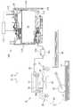
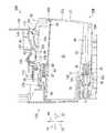
図1に示されるように、プリンタ10は、インクジェット記録方式に基づいて、用紙に対してインク滴を選択的に吐出することにより画像を記録するものである。プリンタ10は、記録ヘッド21と、インク供給装置100(印刷流体供給装置の一例)と、記録ヘッド21及びインク供給装置100を接続するインクチューブ20とを備えている。インク供給装置100には、カートリッジ装着部110が設けられている。カートリッジ装着部110には、複数のインクカートリッジ30(印刷流体カートリッジの一例)が装着され得る。本実施形態においては、シアン・マゼンタ・イエロー・ブラックの各色インクをそれぞれ貯留する4つのインクカートリッジ30C,30M,30Y,30B(各色インクを区別しない場合には、単に「インクカートリッジ30」と称することがある。)が、カートリッジ装着部110の対応する挿入空間111C,111M,111Y,111B(挿入される各インクカートリッジ30の種別(インク色)を区別しない場合には、単に「挿入空間111」と称することがある。)に装着され得る。カートリッジ装着部110には、その一面に開口112が設けられている。インクカートリッジ30は、開口112を通じてカートリッジ装着部110に前方へ挿入され、或いはカートリッジ装着部110から後方へ抜き出される。[Overview of Printer 10]
As shown in FIG. 1, the
インクカートリッジ30には、プリンタ10で使用可能なインク(印刷流体の一例)が貯留されている。カートリッジ装着部110へのインクカートリッジ30の装着が完了した状態において、インクカートリッジ30と記録ヘッド21とは、インクチューブ20で接続されている。記録ヘッド21にはサブタンク28が設けられている。サブタンク28は、インクチューブ20を通じて供給されるインクを一時的に貯留する。記録ヘッド21は、インクジェット記録方式によって、サブタンク28から供給されたインクをノズル29から選択的に吐出する。具体的には、記録ヘッド21に設けられたヘッド制御基板から各ノズル29に対応して設けられたピエゾ素子29Aに選択的に駆動電圧が印加される。これにより、ノズル29から選択的にインクが吐出される。つまり、記録ヘッド21は、カートリッジ装着部110に装着されたインクカートリッジ30に貯留されたインクを消費する。 The
プリンタ10は、給紙トレイ15と、給紙ローラ23と、搬送ローラ対25と、プラテン26と、排出ローラ対27と、排紙トレイ16と、を備えている。給紙トレイ15から給紙ローラ23によって搬送路24へ給送された用紙は、搬送ローラ対25によってプラテン26上へ搬送される。記録ヘッド21は、プラテン26上を通過する用紙に対してインクを選択的に吐出する。これにより、用紙に画像が記録される。プラテン26を通過した用紙は、排出ローラ対27によって、搬送路24の最下流側に設けられた排紙トレイ16に排出される。 The
[インク供給装置100]
図1に示されるように、インク供給装置100は、プリンタ10に設けられている。インク供給装置100は、プリンタ10が備える記録ヘッド21にインクを供給するものである。インク供給装置100は、インクカートリッジ30を装着可能なカートリッジ装着部110を備えている。なお、図1においては、カートリッジ装着部110へのインクカートリッジ30の装着が完了した状態が示されている。つまり、図1において、インクカートリッジ30は装着状態である。[Ink supply device 100]
As shown in FIG. 1, the
[カートリッジ装着部110]
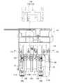
図1から図3に示されるように、カートリッジ装着部110は、カートリッジケース101と、インクニードル102と、タンク103と、光センサ113と、接点106と、ゲート108と、を備えている。カートリッジ装着部110には、シアン、マゼンタ、イエロー、ブラックの各色に対応する4つのインクカートリッジ30が収容可能である。また、インクニードル102、タンク103、光センサ113、接点106、位置決め部107、及びゲート108は、4つのインクカートリッジ30それぞれに対応して、4つずつ設けられている。[Cartridge mounting part 110]
As shown in FIGS. 1 to 3, the
[カートリッジケース101]
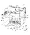
図2に示されるように、カートリッジケース101は、カートリッジ装着部110の筐体を形成する。カートリッジケース101は、天面と、底面と、終面と、開口112とを有する箱形状である。天面は、カートリッジケース101の内部空間の上部である天部を画定する。底面は、カートリッジケース101の内部空間の下部である底部を画定する。終面は、カートリッジケース101の内部空間の天部と底部とをつないでいる。開口112は、終面と前後方向に対向する位置において、カートリッジケース101に形成されている。開口112は、ユーザがプリンタ10を使用するときに対面する面であるプリンタ10のユーザインタフェース面に露出し得る。[Cartridge case 101]
As shown in FIG. 2, the
開口112を通じてカートリッジケース101へインクカートリッジ30が挿抜される。インクカートリッジ30は、カートリッジケース101の底面に設けられたガイド溝109に、インクカートリッジ30の下端部が挿入されることによって、図2において前後方向へ案内される。カートリッジケース101には、内部空間を上下方向に長い4つの挿入空間111C,111M,111Y,111Bに仕切り分ける3つのプレート104が設けられている。プレート104によって仕切り分けられた各挿入空間111C,111M,111Y,111Bに対応するインクカートリッジ30C,30M,30Y,30B(印刷流体カートリッジセットの一例)が収容される。 The
図2に示されるように、カートリッジケース101の4つの挿入空間111C,111M,111Y,111Bは、カートリッジケース101を前方向51に視たときに、左端から右方へ、挿入空間111C,111M,111Y,111Bの順序に並んでいる。挿入空間111Cを既定とするインクカートリッジ30Cが、第1の印刷流体カートリッジの一例である。挿入空間111Mを既定とするインクカートリッジ30Mが、第2の印刷流体カートリッジの一例である。挿入空間111Yを既定とするインクカートリッジ30Yが、第3の印刷流体カートリッジの一例である。つまり、インクカートリッジ30C,30Yは、インクカートリッジ30Mの左右方向の一方と他方に配置されている。また、挿入空間111Bを既定とするインクカートリッジ30Bの左右方向の寸法は、他のインクカートリッジ30C,30M,30Yの左右方向の寸法より大きい。 As shown in FIG. 2, the four
[インクニードル102]
図2に示されるように、インクニードル102(接続部の一例)は、管状の樹脂からなり、カートリッジケース101の終面の下部に位置している。インクニードル102は、カートリッジケース101の終面において、カートリッジ装着部110に装着されたインクカートリッジ30のインク供給部34に対応する位置に配置されている。インクニードル102は、カートリッジケース101の終面から後方へ突出している。[Ink Needle 102]
As shown in FIG. 2, the ink needle 102 (an example of a connection portion) is made of a tubular resin and is located at the lower part of the final surface of the
インクニードル102の周囲には、円筒形状のガイド部105が配置されている。ガイド部105は、カートリッジケース101の終面から後方へ突出し、その突出端が開口している。インクニードル102は、ガイド部105の中心に配置されている。ガイド部105は、インクカートリッジのインク供給部34が内方に進入する形状である。 A
インクカートリッジ30がカートリッジ装着部110に前方へ挿入される過程において、つまりインクカートリッジ30が装着位置へ移動する過程において、インクカートリッジ30のインク供給部34がガイド部105に進入する(図3参照)。さらにインクカートリッジ30がカートリッジ装着部110に前方へ挿入されると、インクニードル102が、インク供給部34に形成されたインク供給口71に挿入される。これにより、インクニードル102とインク供給部34とは連結される。そして、インクカートリッジ30の内部に形成された第2貯留室33に貯留されたインクは、インク供給部34の内部に形成されたインクバルブ室35及びインクニードル102の内部空間を通じてタンク103に流出される。なお、インクニードル102の先端は、平坦であってもよく、尖っていてもよい。また、ガイド部105の形状は、インクカートリッジ30が装着位置に装着可能であれば、如何なる形状であってもよいし、ガイド部105がカートリッジ装着部110に設けられなくてもよい。 In the process of inserting the
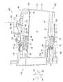
[接点106]
図3に示されるように、カートリッジケース101において1つのインクカートリッジ30が挿入される内部空間の天面における終面付近には4つの接点106が配置されている。4つの接点106は、天面からカートリッジケース101の1つのインクカートリッジ30が挿入される内部空間へ向けて下方に突出している。各図には詳細に示されていないが、4つの接点106それぞれは、左右方向に離れて配置されている。4つの接点106の配置は、後述される1つのインクカートリッジ30の4つの電極65の配置に対応している。各接点106は、導電性及び弾性を有する部材で構成されており、上方へ弾性的に変形可能である。4つの接点106は、カートリッジケース101に収容可能な4つのインクカートリッジ30に対応して、4組が配置されている。すなわち、カートリッジケース101には、16個の接点106が配置されている。なお、接点106の個数及び電極65の個数は任意である。[Contact 106]
As shown in FIG. 3, four
各接点106は、電気回路を介して演算装置に電気的に接続されている。演算装置は、例えばCPU,ROM,RAMなどからなるものであり、例えばプリンタ10のコントローラとしての機能を果たす。各接点106と、当該各接点106と対応する各電極65とが接触して電気的に導通されることによって、電圧Vcが1つ目の電極65に印加されたり、2つ目の電極65がアースされたり、3つ目の電極65にデータを示す信号が送電されたり、4つ目の電極65に演算装置から同期信号が送電されたりする。各接点106と、当該各接点106と対応する各電極65との電気的に導通により、演算装置が、インクカートリッジ30のICに格納されたデータにアクセス可能となる。各接点106から電気回路を通じた出力は演算装置に入力される。 Each
[ロッド125]
図3に示されるように、カートリッジケース101の終面におけるインクニードル102より上方に、ロッド125が形成されている。ロッド125は、カートリッジケース101の終面から後方へ突出している。ロッド125は、円筒形状である。ロッド125は、インクカートリッジ30がカートリッジ装着部110に装着された状態において、つまりインクカートリッジ30が装着位置に位置する状態において、後述する大気連通口96へ挿入される。[Rod 125]
As shown in FIG. 3, a
[光センサ113]
図3に示されるように、カートリッジケース101の天面には、光センサ113が配置されている。光センサ113は、ロッド125よりも後方且つ接点106よりも前方に位置している。光センサ113は、発光部及び受光部を備える。発光部は、受光部よりも右方または左方に、受光部と間隔を空けて設けられている。カートリッジ装着部110への装着が完了したインクカートリッジ30の後述する遮光板67の切欠き66は、発光部及び受光部の間に配置される。換言すれば、発光部及び受光部は、カートリッジ装着部110への装着が完了したインクカートリッジ30の遮光板67の切欠き66を挟んで対向配置されている。[Optical sensor 113]
As shown in FIG. 3, an
光センサ113は、発光部から左右方向に沿って照射された光が受光部で受光されたか否かに応じて異なる検知信号を出力する。例えば、光センサ113は、発光部から出力された光が受光部で受光できない(すなわち、受光強度が所定の強度未満である)ことを条件として、ローレベル信号を出力する。一方、光センサ113は、発光部から出力された光が受光部で受光できた(すなわち、受光強度が所定の強度以上である)ことを条件として、ハイレベル信号を出力する。 The
[ロックシャフト145]
図3に示されるように、ロックシャフト145が、カートリッジケース101の天面付近且つ開口112付近において、カートリッジケース101の左右方向に延出されている。ロックシャフト145は、左右方向に沿って延びる棒状の部材である。ロックシャフト145は、例えば、金属の円柱である。ロックシャフト145の左右方向の両端は、カートリッジケース101の左右方向の両端を確定している壁に固定されている。したがって、ロックシャフト145は、カートリッジケース101に対して回動等の相対移動をしない。ロックシャフト145は、4つのインクカートリッジ30が収納可能な4つの空間に渡って左右方向に延びている。インクカートリッジ30が収容される各空間において、ロックシャフト145の周囲には空間が存在する。したがって、ロックシャフト145に対して、上方へ向かって、また、後方へ向かってインクカートリッジ30のロック面151などがアクセスすることができる。[Rock shaft 145]
As shown in FIG. 3, the
ロックシャフト145は、カートリッジ装着部110に装着されたインクカートリッジ30を装着位置に保持するためのものである。インクカートリッジ30は、カートリッジ装着部110に挿入されて、使用姿勢に回動されることにより、ロックシャフト145に係合する。さらに、ロックシャフト145は、インクカートリッジ30のコイルバネ78,98がインクカートリッジ30を後方へ押す力に抗してインクカートリッジ30をカートリッジ装着部110内に保持する。 The
[位置決め部107]
図3に示されるように、位置決め部107が、カートリッジケース101の天面付近、且つ前後方向において、接点106とロックシャフト145との間に設けられている。位置決め部107は、カートリッジケース101の天面から下方へ突出する凸形状である。位置決め部107は、カートリッジケース101と一体に形成されている。位置決め部107の下端面がインクカートリッジ30の当接面84と当接し得る。位置決め部107の下端面は、接点106の下端より若干上方に位置する。[Positioning unit 107]
As shown in FIG. 3, a
[ゲート108]
図3及び図10に示されるように、ゲート108(凸部の一例)が、カートリッジケース101の天面付近且つ前後方向において、光センサ113と接点106との間に設けられている。ゲート108は、挿入空間111の左右方向の両端に位置するプレート104などの仕切部材から、左右方向に間隔を空けて対となり、左右方向に沿って延び、且つ挿入空間111へ向かって下方に延びる2つの障壁118と、障壁118同士の間に形成された当該所定の間隔を空けて形成された空間であって、障壁118における左右方向の所定の位置の下端から上方へ向かって延びるスリット119と、を有するものである。ゲート108におけるスリット119の左右方向の位置が、各挿入空間111C,111M,111Y,111Bにおいて異なる。スリット119は、各インクカートリッジ30C,30M,30Y,30Bにそれぞれ設けられた遮光板67C,67M,67Y,67Bの左右方向の配置に対応しており、各遮光板67C,67M,67Y,67Bの左右方向の幅より広い。すなわち、各遮光板67C,67M,67Y,67Bは、スリット119を前後方向に通過することができる。[Gate 108]
As shown in FIGS. 3 and 10, a gate 108 (an example of a convex portion) is provided between the
[タンク103]
図1に示されるように、カートリッジケース101の前方にはタンク103が設けられている。タンク103は、内部にインクを貯留可能な箱形状である。タンク103の上部は、大気連通ポート124によって外部へ開口している。これにより、タンク103の内部空間は、大気開放されている。タンク103の内部空間は、前方においてインクニードル102の内部空間と連通している。これにより、インクニードル102を通じてインクカートリッジ30か流出したインクがタンク103に貯留される。タンク103には、インクチューブ20が接続されている。これにより、タンク103の内部空間に貯留されたインクがインクチューブ20を通じて記録ヘッド21へ供給される。[Tank 103]
As shown in FIG. 1, a
図1に示されるように、カートリッジ装着部110には、カートリッジケース101の開口112を開閉するカバー114と、カバー114が開口112を閉じる閉位置にあることを検知するカバーセンサ115と、を有する。カバー114は、左右方向へ延びており、カートリッジケース101の下端付近に設けられた軸116に回動可能に設けられている。カバー114は、プリンタ10の外面の一部をなす概ね平板形状である。 As shown in FIG. 1, the
図1に示されるように、閉位置のカバー114は、軸116から上方へ延びている。カバー114が閉位置にあることにより、カートリッジケース101の開口112が閉じられる。従って、ユーザは、カートリッジ装着部110に対してインクカートリッジ30を挿抜することができない。カバーセンサ115は、閉位置のカバー114の一部を検知可能な位置に配置されている。開位置のカバー114は、閉位置から上端が下方へ降下するように軸116周りに回動されて、軸116から概ね水平方向に沿って後方向52へ延びる。カバー114が閉位置から開位置へ向かって回動されることによって、カバー114は、カバーセンサ115の検知位置から外れる。カバー114が開位置にあることにより、カートリッジケース101の開口が開かれる。従って、ユーザは、カートリッジ装着部110に対してインクカートリッジ30を挿抜することができる。 As shown in FIG. 1, the
図1に示されるように、カートリッジ装着部110は、制御部117を有する。制御部117は、例えば、CPU、メモリなどを有する演算装置である。制御部117は、光センサ113及びカバーセンサ115が出力する信号を受信可能である。制御部117は、カバーセンサ115から出力されたカバー114が閉位置にあることを示す信号を受信したことをトリガーとして、光センサ113が出力する信号に応じて、挿入空間111に挿入されたインクカートリッジ30の種別を判定する。具体的には、インクカートリッジ30の遮光板67における切欠き66の有無によって変化する出力信号に応じて、挿入空間111に挿入されたインクカートリッジ30の種別を判定する。 As shown in FIG. 1, the
詳細には、図12に示されるように、制御部117は、カバーセンサ115が出力する信号がハイレベル信号になったことに応じて、カバー114が開位置になったと判断する(S11:Yes)。そして、制御部117は、光センサ113が出力する信号が、ローレベル信号になったことに応じて、メモリに記憶されているフラグをONにする(S13)。カートリッジ装着部110にインクカートリッジ30が挿入されて、光センサ113を遮光板67が通過することによって、光センサ113が出力する信号がローレベル信号になる。そして、制御部117は、カバーセンサ115が出力する信号がローレベル信号になったことに応じて、カバー114が閉位置になったと判断する(S14:Yes)。 Specifically, as shown in FIG. 12, the
制御部117は、カバー114が閉位置になったと判断した後、接点106を介してIC基板64にアクセス可能か判断する(S15)。制御部117は、IC基板64にアクセスできなければ(S15:No)、制御部117は、カートリッジ装着部110にインクカートリッジ30が装着されていないと判断する(S21)。 After determining that the
制御部117は、IC基板64にアクセス可能であれば、メモリに記憶されているフラグがONであるかを判定する(S16)。フラグがONでなければ(S16:No)、制御部117は、破損などによって遮光板67を有しないインクカートリッジ30が装着されていると判断する(S20)。 If the
制御部117は、フラグがONであれば、光センサ113が出力する信号を判定する(S17)。光センサ113が出力する信号がハイレベル信号であれば、制御部117は、カートリッジ装着部110に種別Aのインクカートリッジ30が装着されたと判断する(S18)。光センサ113の出力は、遮光板67に切欠き66が形成されていれば、ハイレベル信号となる。また、種別Aとは、例えばインクの初期容量が多い大容量カートリッジなどである。 If the flag is ON, the
光センサ113が出力する信号がローレベル信号であれば、制御部117は、カートリッジ装着部110に種別Bのインクカートリッジ30が装着されたと判断する(S19)。光センサ113の出力は、遮光板67に切欠き66が形成されていなければ、ローレベル信号となる。また、種別Bとは、例えばインクの初期容量が多くない小容量カートリッジなどである。 If the signal output by the
[インクカートリッジ30]
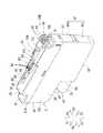
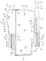
図4〜図6に示されるインクカートリッジ30はインクが貯留される容器である。以下、インクカートリッジ30Bを例として、各インクカートリッジ30の基本的な構成を説明する。インクカートリッジ30C,30M,30Yは、インクカートリッジ30Bとは、インクの色、及び第1貯留室32の容量が異なる。また、遮光板67の左右方向における配置は、各インクカートリッジ30において異なる。これらの相違点は、インクカートリッジ30Bの基本的な構成を説明した後に詳述する。[Ink cartridge 30]
The
図4〜図6に示されているインクカートリッジ30の姿勢は、インクカートリッジ30が装着姿勢にあるときの姿勢、すなわち使用姿勢である。インクカートリッジ30は、後述されるように、前面40と、後面41と、上面39と、下面42とを備えるが、使用姿勢においては、後面41から前面40に向かう方向が前方向51に一致し、前面40から後面41に向かう方向が後方向52に一致し、上面39から下面42に向かう方向が下方向53に一致し、下面42から上面39に向かう方向が上方向54に一致する姿勢である。また、インクカートリッジ30がカートリッジ装着部110に装着されるときに、前面40は前方を向き、後面41は後方を向き、下面42は下方を向き、上面39は、上方を向く。 The posture of the
図4〜図6に示されるように、インクカートリッジ30は、略直方体形状の筐体31を有する。本実施形態においては、筐体31は、その内部に第1貯留室32及び第2貯留室33が形成されている下ケース31L(ケースの一例)と、下ケース31Lに嵌合される上カバー31U(上部部材の一例)とを有する。筐体31は、全体として、左右方向に沿った寸法が細く、上下方向及び前後方向それぞれに沿った寸法が、左右方向に沿った寸法よりも大きい扁平形状である。インクカートリッジ30がカートリッジ装着部110へ挿入されるときに、すなわち使用姿勢において前方を向く筐体31の面が前面40であり、後方を向く筐体31の面が後面41である。側面37,38は、前面40及び後面41とそれぞれ交差して延びることにより前面40及び後面41を繋いでおり、使用姿勢において、それぞれ右方又は左方を向いている。筐体31において、下ケース31Lにおける少なくとも後面41が、第1貯留室32及び第2貯留室33に貯留されたインクの液面を外部から視認可能な透光性を有するものである。上カバー31Uの上面が筐体31の上面である。 As shown in FIGS. 4 to 6, the
なお、本実施形態では、筐体31は、下ケース31L及び上カバー31Uによって外面を構成するが、1個の箱形のケースによって筐体31が構成されてもよい。また、筐体31は、貯留室を区画する内ケースと、外壁を構成する外ケースとに分かれており、外ケース内に内ケースが収容される入れ子構造であってもよい。 In the present embodiment, the outer surface of the
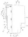
図5に示されるように、後面41は、上部分41Uと下部分41Lとを有する。上部分41Uは、下部分41Lよりも上方に位置する。下部分41Lは、上部分41Uよりも前方に位置する。上部分41U及び下部分41Lは、いずれも平面であり、相互に直交せずに交差している。下部分41Lは、下面42に近づくほど前面40に近くなるように上下方向に対して傾斜している。 As shown in FIG. 5, the
図6に示されるように、下面42は、前端が後端よりも下方に位置するように、前後方向に対して傾斜した傾斜面である。下面42(傾斜面)の前端は、後述するIC基板64よりも前方に位置している。下面42(傾斜面)の後端は、後面41の下部分41Lの下端と繋がっている。下面42の傾斜角は、水平方向に対して2°〜4°が好ましい。 As shown in FIG. 6, the
図6に示されるように、筐体31は、下面42より上方に位置しており、前面40の下端と連続して後方へ延びるサブ下面48を有する。本実施形態において、サブ下面48の前端はインク供給部34の前端よりも前方に位置し、サブ下面48の後端は、インク供給部34の前端より後方に位置する。下面42とサブ下面48とは段差面49によって連続している。インク供給部34は、サブ下面48の下方、且つ下面42の上方において、段差面49から前方へ延びている。なお、サブ下面48の前端の位置は任意であり、例えば、インク供給部34の前端よりも後方に位置していてもよい。 As shown in FIG. 6, the
図4〜図6に示されるように、筐体31の上面39には、凸部43が設けられている。凸部43は、上面39における左右方向の中央からオフセットした位置において前後方向に沿って延びている。凸部43の後端において後方且つ下方を向く面がロック面151である。ロック面151は、筐体31の上面39よりも上方に位置している。ロック面151は、上下方向に沿って延びている。ロック面151は、カートリッジ装着部110にインクカートリッジ30が装着された状態において、ロックシャフト145と後方へ向かって接触し得る面である。ロック面151がロックシャフト145と後方へ向かって接触することにより、インクカートリッジ30がコイルバネ78の付勢力に抗してカートリッジ装着部110に保持される。 As shown in FIGS. 4 to 6, a
凸部43においてロック面151より前方には、水平面154がロック面151と連続して設けられている。水平面154は、左右方向と前後方向に沿って拡がる面である。水平面154より前方には、傾斜面155が水平面154と連続して設けられている。傾斜面155は、上方且つ前方を向いている。傾斜面155の水平方向に対する傾斜角は、15°〜25°が好ましい。水平面154を介してロック面151と傾斜面155とが連続しているので、ロック面151と傾斜面155との境界が尖った山形状とならない。傾斜面155は、前後方向において、後述されるIC基板64とロック面151との間に位置する。傾斜面155及び水平面154により、インクカートリッジ30がカートリッジ装着部110に挿入される過程において、ロックシャフト145が傾斜面155及び水平面154に当接しながらロック面151より後方まで円滑に案内される。 A
筐体31の上面39において、ロック面151より後方には、操作部90が設けられている。筐体31の上面39の前端及び後端には、上面39の前後方向の中央部分より下方に位置するサブ上面91が形成されている。サブ上面91の上方において空間を隔てて操作部90が配置されている。操作部90は、上面39のその他の部分とサブ上面91との境界付近から上方へ向けて凸部43と同程度まで上方へ突出し、さらに後方且つ下方へ斜め下方向に折れ曲がった平板形状である。操作部90とサブ上面91との間には、操作部90及びサブ上面91に連続しており、且つ後方へ延びるリブ94が設けられている。左右方向に沿ったリブ94の寸法は、左右方向に沿った操作部90の寸法及びサブ上面91の寸法のそれぞれより小さい。 On the
操作部90において、上方且つ後方を向く面が操作面92である。操作面92とサブ上面91とは、前後方向に沿った方向における位置が重複している。換言すれば、インクカートリッジ30を下方に視たとき、操作面92とサブ上面91とは重複した位置にある。操作面92には、複数の突起、例えば、左右方向に沿って延出する複数の突条93が、前後方向に間隔を隔てて形成されている。複数の突起としての突条93により、ユーザが操作面92を認識しやすくなり、また、ユーザが操作面92を指で操作するときに、指が操作面92に対して滑りにくくなる。 In the
操作面92は、インクカートリッジ30を下方に視たときに視認可能であり、且つ、インクカートリッジ30を前方に視たときに視認可能である。操作面92は、インクカートリッジ30がカートリッジ装着部110に装着された状態からインクカートリッジ30を取り出すために、ユーザが操作するための面である。なお、操作部90は、筐体31と一体に成型されるなどして、筐体31に対して固定されており、筐体31に対して回動などの相対移動をしないように構成されている。したがって、操作面92にユーザから加えられる力は、方向を変えずに筐体31にそのまま伝達される。 The
図4〜図6に示されるように、上カバー31Uにより構成される筐体31の上面39において、凸部43の前方には、凸部83が設けられている。凸部83の左右方向の位置は凸部43と同じである。凸部83は凸部43と連続して前方へ延びている。凸部83の後部における上端面が当接面84である。当接面84は、傾斜面155の下端と連続しており、上方を向いている。当接面84は、前後方向において、後述されるIC基板64とロック面151との間に位置する。当接面84は、インクカートリッジ30がカートリッジ装着部110に挿入された状態において位置決め部107と当接する。当接面84は、IC基板64に対して相対移動しない面であり、本実施形態では、IC基板64を支持する部材、すなわち上カバー31Uと同一の部材に形成されている。なお、傾斜面155は任意の構成であり、当接面84とロック面151との間が連続した面で構成されていないくてもよい。例えば、当接面84を構成する凸部83と、ロック面151を構成する凸部43とが、連続せずに独立して各々が上方に突出していてもよい。 As shown in FIGS. 4 to 6, a
なお、インクカートリッジ30の前面40、後面41、上面39、下面42、及び側面37,38は、必ずしも1つの平面をなしている必要はない。すなわち、装着姿勢のインクカートリッジ30を後方に視たときに視認し得る面であり、且つ、装着姿勢のインクカートリッジ30の前後方向の中心よりも前方に位置する面が前面40である。本実施形態においては、下面42とサブ下面48とをつなぐ段差面49は、サブ下面48とサブ上面91とをつなぐ前面40とともに、前面40の一部をなしているといえる。段差面95も前面40の一部をなしている。一方、インクカートリッジ30は、サブ下面48、サブ上面91を有しなくてもよい。換言すると、インクカートリッジ30の前面40は、上面39と下面42とを連続的につなぐ一つの面であってもよい。装着姿勢のインクカートリッジ30を前方に視たときに視認し得る面であり、且つ、装着姿勢のインクカートリッジ30の前後方向の中心よりも後方に位置する面が後面41である。装着姿勢のインクカートリッジ30を下方に視たときに視認し得る面であり、且つ、装着姿勢のインクカートリッジ30の上下方向の中心よりも上方に位置する面が上面39である。装着姿勢のインクカートリッジ30を上方に視たときに視認し得る面であり、且つ、装着姿勢のインクカートリッジ30の上下方向の中心よりも下方に位置する面が下面42である。側面37,38に関しても同様である。 The
図4〜図6に示されるように、上面39には、上方に突出する遮光板67が形成されている。遮光板67は、上カバー31Uと一体に形成されている。遮光板67は、前後方向に延びている。遮光板67は、凸部83よりも前方に位置している。遮光板67は、後述する電気的インターフェース60よりも前方かつ下方に位置している。本実施形態において、遮光板67は、例えば光を吸収可能な色材料(黒色顔料)を含む樹脂製の板である。その他の形態としては、遮光板67は、光を透過可能な板の側面にアルミ箔などの光が透過不能な材料が貼り付けられたものであってもよい。遮光板67において、右方向55及び左方向56を向く両側面が、それぞれ遮光面に相当する。 As shown in FIGS. 4 to 6, a light-shielding
図6に示されるように、凸部43の水平面154の前端154Aと遮光板67の上面67Cの前端とを含み、且つ左右方向に沿って延びる仮想平面60を定義することができる。本実施形態における仮想平面60は、前方向51に向かって下方に傾斜する面である。そして、仮想平面60より下方にIC基板64が配置されている。詳述すると、筐体31の上壁39よりも上方には、仮想平面60と上壁39の上面とで囲まれた領域が形成され、IC基板64は、当該領域内に配置されている。さらに、水平面154の前端154Aと遮光板67の上面67Cの前端との間で、上壁39の上面と仮想平面60とで挟まれた領域には、遮光板67の右側面及び左側面、切欠き66、IC基板64、当接面84、傾斜面155が配置されている。すなわち、インクカートリッジ30に対して左右方向または上方からアクセスされ得る部材が、当該領域内に配置されている。より詳しくは、本実施形態におけるインクカートリッジ30において、仮想平面60と交わる部材は、凸部43の水平面154の前端154Aと、遮光板67の上面67Cの前端との間にはない。すなわち、インクカートリッジ30の上壁39において、最も高い位置にある部材が水平面154の前端154Aであり、水平面154の前端154Aより前方にある部材のなかで前端154Aの次に高い位置にある部材が遮光板67の上面67Cの前端である。 As shown in FIG. 6, a
遮光板67においては、例えば左から右に進行する光センサ113(光学センサの一例)の光を遮断する。より詳細には、光センサ113の発光部から出力された光が受光部に到達するまでの間に遮光板67に当たることによって、受光部に到達する光の強度が所定の強度未満、例えば、ゼロとなる。遮光板67は、光が進むのを完全に遮断してもよいし、光を部分的に減衰させてもよいし、光の進行方向を曲げてもよいし、光を全反射させてもよい。本実施形態では、遮光板67には切欠き66(透光空間の一例)が形成されている。切欠き66は、遮光板67の上端から下方へ凹む空間であり、前後方向及び左右方向に拡がっている。切欠き66が光センサ113に位置することにより、光センサ113の発光部から出力された光は、受光部に到達するまでに遮断されない。このような切欠き66の有無によって、インクカートリッジ30の種別、すなわちインクカートリッジ30が貯留するインクの種類や初期量などが判別可能となる。 The light-shielding
遮光板67において、前方向51を向く面が干渉面68である。干渉面68は、インクカートリッジ30がカートリッジ装着部110において既定と異なる挿入空間111に挿入される過程において、ゲート108と当接する面である。遮光板67の両側面は、干渉面68より後方に位置する。換言すれば、干渉面68が、遮光板67の前面である。干渉面68は、筐体31の上面39から上方へ延びて、上下方向及び左右方向に拡がる平面である。また、遮光板67において、上面と干渉面68とを繋ぎ、前方向且つ上方向を向く面が傾斜面69である。干渉面68の上端は、凸部43の上面より若干下方にある。すなわち、干渉面68は、後述されるIC基板64の電極65より前方且つ下方にある。 In the light-shielding
図4〜図6に示されるように、凸部83の上端であって、遮光板67と凸部43との間には、IC基板64(電気的インターフェースの一例)が設けられている。IC基板64は、当接面84より前方に位置して下方へ凹む凹空間において、凸部83に下方から支持されている。各図には詳細に現れていないが、凸部83の凹空間には光硬化性樹脂が充填されて凸部83にIC基板64を接着している。IC基板64は、インクカートリッジ30がカートリッジ装着部110に装着される途中において接点106と導通し、かつインクカートリッジ30がカートリッジ装着部110に装着された状態においても接点106と導通する。 As shown in FIGS. 4 to 6, an IC substrate 64 (an example of an electrical interface) is provided between the light-shielding
IC基板64は、シリコンなどで形成された基板に、IC(各図には現れていない)と、4つの電極65が搭載されたものである。4つの電極65は、左右方向に沿って並んでいる。ICは、半導体集積回路であり、インクカートリッジ30に関する情報、例えば、ロット番号や製造年月日、インク色などの情報を示すデータが読み出し可能に格納されている。また、IC基板4は、可橈性を有するフレキシブル基板にIC及び電極が設けられて構成されてもよい。 The
各電極65はICと電気的に接続されている。各電極65は、それぞれが前後方向に沿って延出されており、4つの電極65は、左右方向に離間されて配置されている。各電極65は、IC基板64の上面に電気的にアクセス可能に露出されている。 Each
上面39の外面のうち前端にあるサブ上面91の後端から、段差面95が上方へ延びている。段差面95は前方を向く面である。段差面95には、大気連通口96が形成されている。つまり、大気連通口96は、筐体31の上下方向の寸法の中心より上方に配置されている。大気連通口96は、段差面95に形成された略円形の開口であって、カートリッジ装着部110のロッド125の外径より大きな内径を有している。インクカートリッジ30がカートリッジ装着部110に装着される過程において、ロッド125が大気連通口96に進入する。大気連通口96に進入したロッド125は、大気連通口96を封止するバルブ97をコイルバネ98の付勢力に抗して後方へ移動させる。バルブ97が後方へ移動して大気連通口96から離れることにより、第1貯留室32が大気開放される。なお、大気連通口96を封止する部材は、バルブ97に限定されない。例えば、段差面95から剥離可能なシールによって大気連通口96が封止されてもよい。 A stepped
[筐体31の内部構造]
図7に示されるように、筐体31の内部には、第1貯留室32、第2貯留室33、インクバルブ室35、及び大気バルブ室36が形成されている。筐体31の内部には、第1貯留室32と大気バルブ室36とを隔てる隔壁44と、第1貯留室32と第2貯留室33とを隔てる下壁45とが設けられている。隔壁44及び下壁45は、それぞれが前後方向及び左右方向に拡がる壁である。隔壁44と下壁45とは、上下方向に対向して配置されている。[Internal structure of housing 31]
As shown in FIG. 7, a
図7に示されるように、第1貯留室32は、隔壁44の下面44A(内上面の一例)により上端が画定され、下壁45の上面45Aにより下端が画定され、前面40、後面41及び側面37,38それぞれの反対の面である各内面40A,41A,37A,38A(内前面、内後面の一例)により前端、後端、両側端がそれぞれ画定された空間である。隔壁44には貫通孔46が形成されている。貫通孔46によって、第1貯留室32と大気バルブ室36とが連通されている。なお、図7においては、内面37Aが図に現れていない。 As shown in FIG. 7, the upper end of the
第2貯留室33は、筐体31の内部空間において、使用姿勢における第1貯留室32の下方に位置してインクを貯留する。第2貯留室33がインクを貯留可能な容積は、第1貯留室32がインクを貯留可能な容積より小さい。 The
第2貯留室33は、下壁45の下面により上端が画定され、下面42の上面により下端が画定され、後面41及び側面37,38の反対の面である各内面により後端及び両側端がそれぞれ画定された空間である。第2貯留室33とインクバルブ室35との間には隔壁50が形成されている。隔壁50によって第2貯留室33の前端が画定されている。第2貯留室33は、下壁45に形成された連通口47によって第1貯留室32と連通されている。また、第2貯留室33は、隔壁50に形成された貫通孔99によって、インクバルブ室35と連通されている。 The upper end of the
大気バルブ室36には、バルブ97及びコイルバネ98が収容されている。大気バルブ室36は、段差面95に形成された大気連通口96によって外部と連通している。バルブ97は、大気連通口96を封止する閉位置と、大気連通口96から離れた開位置に移動可能である。コイルバネ98は、前後方向に沿って伸縮可能に配置されており、バルブ97を大気連通口96へ当接する方向、すなわち前方向51へ付勢している。コイルバネ98のバネ定数は、インク供給部34のコイルバネ78のバネ定数よりも小さい。 A
インク供給部34(供給部の一例)は、円筒形状の外形をなしている。より詳細には、インク供給部34は、前端が開口する筒75と、パッキング76とを備えている。筒75は、段差面49から前方へ突出している。筒75の内部空間が、インクバルブ室35である。筒75の前端は、インクカートリッジ30の外部に開口している。筒75の前端部には、パッキング76が位置している。 The ink supply unit 34 (an example of the supply unit) has a cylindrical outer shape. More specifically, the
インクバルブ室35には、バルブ77及びコイルバネ78が収容されている。バルブ77は、前後方向に沿って移動することにより、パッキング76の中央に貫通されたインク供給口71を開閉する。コイルバネ78はバルブ77を前方へ付勢している。したがって、外力が付与されていない状態において、バルブ77は、パッキング76のインク供給口71を閉じている。 A
パッキング76は、中央に貫通孔が形成された円盤形状の部材である。パッキング76は、例えば、ゴムやエラストマのような弾性材料から形成されている。パッキング76の中央が前後方向に貫通されて筒状の内周面が形成されている。パッキング76は、当該筒状の内周面によりインク供給口71が形成されている。インク供給口71の内径は、インクニードル102の外径より若干小さい。 The packing 76 is a disk-shaped member having a through hole formed in the center. The packing 76 is made of an elastic material such as rubber or elastomer. The center of the packing 76 is penetrated in the front-rear direction to form a tubular inner peripheral surface. In the packing 76, the
バルブ77がインク供給口71を閉じている状態において、インクカートリッジ30がカートリッジ装着部110に挿入されると、インク供給口71にインクニードル102が進入する。インクニードル102は、パッキング76を弾性変形しつつ、その外周面がインク供給口71を画定する内周面に液密に接触する。インクニードル102の先端がパッキング76に形成されたインク供給口71を通過してインクバルブ室35へ進入すると、インクニードル102の先端がバルブ77に当接する。さらにインクカートリッジ30がカートリッジ装着部110へ挿入されることにより、インクニードル102がバルブ77をコイルバネ78の付勢力に抗して後方へ移動させる。これにより、インクバルブ室35に貯留されているインクがインクニードル102の内部空間へ流通することが可能となる。
When the
[インクカートリッジ30における各部分の配置]
図7に示されるように、干渉面68は、第1貯留室32の前端を画定する内面40Aより後方に位置する。また、図4,5に示されるように、干渉面68の左右方向の両端から後方へ遮光板67の両側面が延びているので、干渉面68と遮光板67の両側面は、前方向51から視てオーバーラップしている。[Arrangement of each part in the ink cartridge 30]
As shown in FIG. 7, the
図9(A)に示されるように、インクカートリッジ30Bの干渉面68は、左右方向において幅W1を有している。筐体31の上面39の左右方向の両端と、干渉面68の左右方向の両端、すなわち遮光板67の左右方向の両端との最小幅W2は、幅W1より広い(W1<W2)。IC基板64は、ロック面151より前方、且つ下方に配置されている。インクカートリッジ30Bにおいては、干渉面68は、IC基板64と左右方向において重複しない。 As shown in FIG. 9A, the
[各インクカートリッジ30の比較]
図9に示されるように、インクカートリッジ30Bと、インクカートリッジ30C,30M,30Yとは、筐体31における左右方向の寸法が異なる。インクカートリッジ30Bの筐体31の左右方向の寸法は、インクカートリッジ30C,30M,30Yの筐体31の左右方向の寸法より大きい。その結果、インクカートリッジ30Bの第1貯留室32の容量は、インクカートリッジ30C,30M,30Yの第1貯留室32の容量より大きい。[Comparison of each ink cartridge 30]
As shown in FIG. 9, the
図9(A)に示されるように、インクカートリッジ30Bの凸部43は、上面39における左右方向の中央からオフセットした位置に配置されている。他方、図9(B),(C),(D)に示されるように、インクカートリッジ30C,30M,30Yの凸部43は、上面39における左右方向の中央に配置されている。 As shown in FIG. 9A, the
図9に示されるように、各インクカートリッジ30C,30M,30Y,30Bにおいては、左右方向における干渉面68の配置が異なる。図9において、IC基板64を含み、前後方向及び上下方向と平行な仮想平面59として示されている。図9(B)に示されるように、インクカートリッジ30Mの干渉面68は、仮想平面59と交わる位置に配置されている。図9(C)に示されるように、インクカートリッジ30Cの干渉面68は、仮想平面59に対して左方に配置されている。図9(D)に示されるように、インクカートリッジ30Yの干渉面68は、仮想平面59に対して右方に配置されている。図9(A)に示されるように、インクカートリッジ30Bの干渉面68は、仮想平面59に対して、インクカートリッジ30C,30M,30Yの筐体31の左右方向の端がある位置(図9(A)における破線57)よりも外方に配置されている。換言すれば、インクカートリッジ30Bの干渉面68と仮想平面59との左右方向に沿った距離L1は、インクカートリッジ30C,30M,30Yの仮想平面59と筐体31の左右方向の端との左右方向に沿った最短距離L2より長い(L1>L2)。 As shown in FIG. 9, in each of the
図6に示されるように、前後方向において、筐体31の後面41から前面に向かって、ロック面151、IC基板64、遮光板67の順番に並んで配置されている。また、上下方向において、上方向54へ向かって遮光板67、IC基板64、ロック面151の順に、それぞれの最高位置が並ぶように配置されている。また、図9に示されるように、ロック面151の左右方向の寸法W3は、遮光板67の左右方向の寸法W1より長い。 As shown in FIG. 6, in the front-rear direction, the
[インクカートリッジ30がカートリッジ装着部110へ装着される動作]
以下、インクカートリッジ30(一例としてインクカートリッジ30M)がカートリッジ装着部110に装着される過程が説明される。[Operation in which the
Hereinafter, the process of mounting the ink cartridge 30 (as an example, the
図7に示されるように、カートリッジ装着部110に装着される前のインクカートリッジ30において、バルブ77は、パッキング76のインク供給口71を閉じている。これにより、インクバルブ室35からインクカートリッジ30の外部へのインクの流通は遮断されている。また、バルブ97は、大気連通口96を閉じている。これにより、第1貯留室32は、大気開放されていない。また、カートリッジ装着部110において、カートリッジケース101の開口102は、閉位置のカバー114により閉じられている。ユーザは、カートリッジ装着部110へのインクカートリッジ30の挿抜において、閉位置のカバー114を開位置へ回動する。 As shown in FIG. 7, in the
インクカートリッジ30は、筐体31の前面40を前方向51を向いており、且つ上面39を上方向54を向いた姿勢、すなわち装着姿勢で、カートリッジ装着部110の開口112を通じてカートリッジケース101へ挿入される。筐体31の後面41の上部分41Uは下部分41Lよりも後方に位置している、すなわち、ユーザの近くに位置しているので、ユーザは、上部分41Uを押しつつインクカートリッジ30をカートリッジ装着部110に対して前方へ挿入する。インクカートリッジ30の下部、カートリッジケース101の下方のガイド溝109に進入した状態となる。 The
図8に示されるように、インクカートリッジ30がカートリッジケース101へ挿入されると、インク供給部34がガイド部105に進入する。また、ロッド125が大気連通口96に進入する。 As shown in FIG. 8, when the
また、図8,10に示されるように、干渉面68がカートリッジ装着部110のゲート108に到達する。例えば、カートリッジケース101の挿入空間111Mに対応するインクカートリッジ30Mが挿入されて筐体31がガイド溝109に沿って前方向51に進行すると、左右方向において、干渉面68の位置とゲート108のスリット119の位置とが合致する。したがって、干渉面68は、ゲート108のリブに当接することなく、スリット119を通過してゲート108の前方へ進行する。これにより、光センサ113の発光部と受光部との間に、遮光板67が位置する。 Further, as shown in FIGS. 8 and 10, the
他方、図11に示されるように、例えば、インクカートリッジ30Cが、当該インクカートリッジ30Cと対応しない挿入空間111Mに挿入されて筐体31がガイド溝109に沿って前方向51に進行すると、左右方向において、干渉面68の位置とゲート108のスリット119の位置とが合致しない。したがって、干渉面68は、ゲート108のリブに当接して、スリット119を通過できない。その結果、図11に示される状態より更に前方へインクカートリッジ30Cを挿入することができない。したがって、インクカートリッジ30Cのバルブ77がインクニードル102によってパッキング76から離間しない。 On the other hand, as shown in FIG. 11, for example, when the
図8に示されるように、インクカートリッジ30Mの前面40がカートリッジケース101の終面付近まで挿入されると、インクニードル102がインク供給口71へ進入して、バルブ77をコイルバネ78の付勢力に抗してパッキング76から離間させる。これにより、インク供給部34が位置決めされる。インクカートリッジ30Mには、コイルバネ78の付勢力が後方へ付与される。また、大気連通口96に進入したロッド125は、バルブ97と当接して、コイルバネ98の付勢力に抗してバルブ97を大気連通口96から離間させる。これにより、第1貯留室32が貫通孔46、バルブ室36及び大気連通口96を介して大気開放される。 As shown in FIG. 8, when the
インクカートリッジ30Mには、圧縮されたコイルバネ78,98により生ずる後方向52への付勢力が作用する。各コイルバネ78,98によりそれぞれ生ずる付勢力の大きさは、バネ定数と自然長から圧縮された距離とにより決まる。コイルバネ98のバネ定数は、コイルバネ78のバネ定数より小さく、また、コイルバネ78が圧縮された距離(バルブ77がインク供給口71から離れた距離)は、コイルバネ98が圧縮された距離(バルブ97が大気連通口96から離れた距離)よりも長い。その結果、インクカートリッジ30Mがカートリッジ装着部110に装着された状態において、コイルバネ78により生ずる付勢力の大きさは、コイルバネ98により生ずる付勢力の大きさより大きい。 A urging force in the
また、凸部43がロックシャフト145へ到達し、傾斜面155がロックシャフト145に対して摺動する。インクカートリッジ30Mには、後面41の上部分41Uをユーザが前方へ押すことにより、図7における反時計回りに回転モーメントが加わっている。しかし、傾斜面155とロックシャフト145との当接により、この回転モーメントに反して、インクカートリッジ30Mは、インクニードル102が挿入されたパッキング76のインク供給口71の中心Cを回動中心として回動する。インクカートリッジ30Mにおける中心Cの位置は、インクニードル102の形状とインク供給口71の形状によるが、インクニードル102と筒状のインク供給口34の内面とが接触する部分の中心が仮想的な回動中心である。本実施形態では、インクニードル102における、インク供給口71を画定するパッキング76の内周面が接触している部分の中心を仮想的な回動中心として時計回りに回動する。このときのインクカートリッジ30Mの姿勢が第2姿勢と称される。 Further, the
なお、筐体31の下面42が前後方向に対して傾斜した傾斜面であることにより、下面42とカートリッジケース101のガイド溝109の底面との間には、前述した回動(時計回りの回動)のためのスペースがある。また、ロッド125の外径よりも大気連通口96の内径が大きいので、ロッド125と大気連通口96との間には、回動(時計回りの回動)のためのスペースが有り、装着状態のインクカートリッジ30において、ロッド125と大気連通口96とは当接しない。すなわち、ロッド125と大気連通口96との間においては、上下方向の位置決めがなされていない。 Since the
インクカートリッジ30がカートリッジケース101に挿入されることにより、接点106の下方にIC基板64が到達する。前述した回動によって、第2姿勢のインクカートリッジ30において、IC基板64の電極65と接点106との間には上下方向において空間が存在する。つまり、電極65と接点106とは離間している。また、位置決め部107の下方に当接面84が到達するが、第2姿勢のインクカートリッジ30において、位置決め部107と当接面84との間には上下方向において空間が存在する。つまり、位置決め部107と当接面84とは離間している。 When the
コイルバネ78の付勢力に抗して、インクカートリッジ30が前方へ挿入されると、凸部43の傾斜面155及び水平面154がロックシャフト145よりカートリッジケース101の終面に近い位置となる。第2姿勢のインクカートリッジ30において、ロック面151は、ロックシャフト145より下方に位置する。 When the
インクカートリッジ30には、後面41の上部分41Uをユーザが前方へ押すことにより、図8における反時計回りに回転モーメントが加わっている。一方、大気バルブ室36に設けられたコイルバネ98の付勢力によって、インクカートリッジ30には時計回りの回転モーメントが生じる。傾斜面155及び水平面154がロックシャフト145と当接しなくなることにより、ユーザの力によって、コイルバネ98の付勢力に抗して、インクカートリッジ30は、インクニードル102が挿入されたパッキング76のインク供給口71の中心Cを回動中心として図8における反時計回りに回動する。そして、当接面84が下方から位置決め部107と当接する。 A rotational moment is applied to the
インクカートリッジ30が図3に示される姿勢にあるときに、ロック面151は、後方へ向かってロックシャフト145と向かい合う。ユーザがインクカートリッジ30を前方へ押し込むことを止めると、インクカートリッジ30は、コイルバネ78の付勢力によって後方へ移動する。ロック面151は後方へ向かってロックシャフト145と向かい合っているので、インクカートリッジ30が後方へ移動すると、ロック面151がロックシャフト145と当接する。これにより、インクカートリッジ30が後方へ移動することが規制される。また、当接面84が下方から位置決め部107と当接することにより、インクカートリッジ30が上方へ移動すること、すなわち中心Cを回動中心として反時計回りに回動することが規制される。その結果、インクカートリッジ30はカートリッジ装着部110内に位置決めされて装着が完了した状態となる。このときのインクカートリッジ30の姿勢が第1姿勢と称される。すなわち、インクカートリッジ30は、中心Cを回動中心として回動することによって、第1姿勢と第2姿勢とに姿勢変化可能である。 When the
なお、第1姿勢において、インクカートリッジ30には、後述される力が作用する。インクカートリッジ30は、自重、IC基板64が接点106から受ける付勢力、及び大気バルブ室36に設けられたコイルバネ98による時計回りの回転モーメント、によって、第1姿勢から第2姿勢へ姿勢変化する方向、すなわち中心Cを回動中心として下方に移動しようとする力が作用する。一方、インクバルブ室35のコイルバネ78によって生じる後方向52への付勢力がロック面151に働くことによって、インクカートリッジ30には、反時計回りの回転モーメントが生じ、中心Cを回動中心として上方に移動しようとする力が生じる。また、当接面84と位置決め部107とが当接しており、当接面84がインクカートリッジ30に働く上方向54の力の成分をうけることにより、インクカートリッジ30が上下方向に対して位置決めされている。 In the first posture, a force described later acts on the
第1姿勢において、ロックシャフト145は、ロック面151の下端から前後方向に延びる面156とは上下方向に離間しているので、ロックシャフト145はインクカートリッジ30の上下方向に位置決めに関与していない。したがって、インクカートリッジ30は、カートリッジ装着部110においてカートリッジケース101とは別体に設けられたロックシャフト145ではなく、カートリッジケース101と一体に設けられ、ロックシャフト145よりも接点106に近い位置に配置された位置決め部107において上下方向の位置決めがなされている。 In the first posture, the
図3に示されるように、第1姿勢のインクカートリッジ30において、ロック面151の上端は、中心Cを中心とし、かつロックシャフト145を通過する仮想円弧58より外方に位置する。また、ロック面151の下端は、仮想円弧58の内方に位置する。第1姿勢のインクカートリッジ30は、インク供給口71とインクニードル102との接触位置、及びロック面151とロックシャフト145との当接位置において位置決めされた状態で、コイルバネ78の後方向52への付勢力を受ける。これにより、インクカートリッジ30には、前方且つ上方へ向かうモーメントが生じる。このモーメントは、インクカートリッジ30を中心Cを回動中心として反時計回りに回動させる力の大きさでもある。 As shown in FIG. 3, in the
第1姿勢のインクカートリッジ30において、IC基板64の各電極65は、接点106を上方へ弾性変形させつつ電気的に接触する。このとき、IC基板64は接点106の弾性変形によって下方へ付勢されるが、前述されたモーメントによって、インクカートリッジ30は、IC基板64が接点106を弾性変形させている状態に保持される。また、インクカートリッジ30は、図8における反時計回りに回動する過程において、中心Cよりも後方且つロック面151よりも前方にあるIC基板64の電極65が下方から上方へ向かって接点106と当接して電気的に導通される。挿抜のときのインクカートリッジ30の移動方向である前後方向と、IC基板64の電極65と接点106とが接離する上下方向とが交差しているので、IC基板64の電極65と接点106とが接触しながら前後方向へ相対移動することが抑制され、電極65の削りカスなどの異物の発生が抑制される。 In the
ユーザは、カートリッジ装着部110にインクカートリッジ30が装着した後、開位置のカバー114を閉位置へ回動する。カバー114が開位置から閉位置になると、カバーセンサ115がカバー114を検知した信号を出力する。制御部117は、このカバーセンサ114の信号を受信したことをトリガーとして、光センサ113が出力する信号に基づいて、装着されているインクカートリッジ30の遮光板67における切欠き66の有無を判定する。そして、切欠き66の有無に応じてインクカートリッジ30の初期容量やインクの組成などの種別を判定する。なお、切欠き66の有無と種別の関係は、予め定められたデータとして、制御部117のメモリに格納されている。 After the
インクカートリッジ30がカートリッジ装着部110から脱抜されるときには、ユーザは、カバー114を閉位置から開位置へ回動させた後、インクカートリッジ30の操作面92を下方へ押す。インクカートリッジ30が第1姿勢である状態において、操作面92は、上方かつ後方を向いているので、インクカートリッジ30がカートリッジ装着部110に対して位置決めされた状態から解除する際に、ユーザが操作面92を操作すると、インクカートリッジ30には下方及び前方へ力が作用する。前方へ作用する力によって、ロック面151がロックシャフト145から離れる。下方へ作用する力によって、インクカートリッジ30が図3における時計回りに回動する。これにより、図8に示されるように、当接面84が位置決め部107から離間し、また、IC基板64の電極65が接点106から離間する。また、ロック面151がロックシャフト145よりも下方に位置する。すなわち、インクカートリッジ30が第1姿勢から第2姿勢へ姿勢変化する。インクカートリッジ30の第1姿勢から第2姿勢への姿勢変化に伴い、IC基板64、ロック面151がそれぞれ接点106、ロックシャフト145から離間すると、コイルバネ78の付勢力によって、インクカートリッジ30はカートリッジ装着部110に対して後方へ移動する。これにより、ユーザは筐体31を挟み持ってインクカートリッジ30をカートリッジ装着部110から取り出すことができる。インクカートリッジ30がカートリッジ装着部110から取り出されるときに、遮光板57は、ゲート108のスリット119を通って、ゲート108より後方へ抜け出る。 When the
[本実施形態の作用効果]
本実施形態によれば、干渉面68がIC基板64の電極65より前方且つ下方に配置されているので、カートリッジ装着部110の挿入空間111にインクカートリッジ30が挿入される過程において、干渉面68に対応するゲート108がIC基板64の電極65に接触するおそれが軽減される。[Action and effect of this embodiment]
According to the present embodiment, since the
また、インクカートリッジ30が遮光板67を有するので、遮光板67の切欠き66の有無を光センサ113により検知することによって、インクカートリッジ30の種別が判定可能である。 Further, since the
また、干渉面68と遮光板67の側面とは、少なくとも一部が前方向51から視てオーバーラップしているので、干渉面68と遮光板67の側面との配置が上下方向に対して抑えられたものとなる。 Further, since at least a part of the
また、干渉面68の左右方向の幅W1は、筐体31の上面39の左右方向の両端と干渉面68の左右方向の両端との最小幅W2より狭いので、換言すれば、最小幅W2が幅W1より広いので、筐体31の上面39において干渉面68及び遮光板67の左右方向の両側に比較的幅広の空間が存在する。これにより、当該空間に対応するカートリッジ装着部110の挿入空間111の位置にインクカートリッジ30とアクセスする部品、例えば、IC基板64などを配置することができる。 Further, the width W1 in the left-right direction of the
また、干渉面68が遮光板67の前面として構成されているので、干渉面68が簡易な構造となる。 Further, since the
また、干渉面68と遮光板67の上面とを繋ぐ傾斜面69が設けられているので、インクカートリッジ30が上カバー31Uを下方として床に落下などしたときに、干渉面68及び遮光板67が損傷するおそれが軽減される。 Further, since the
また、インクカートリッジ30Bにおいては、干渉面68とIC基板64とが左右方向において重複しないので、カートリッジ装着部110の挿入空間111Bにインクカートリッジ30Bが挿入される過程において、干渉面68に対応するゲート108がIC基板64に接触するおそれが更に軽減される。 Further, in the
また、IC基板64は、ロック面151より前方、且つ下方に配置されているので、カートリッジ装着部110の挿入空間111にインクカートリッジ30が挿入される過程において、ロックシャフト145がIC基板64や干渉面68に接触するおそれが軽減される。 Further, since the
また、IC基板64及び干渉面68が上カバー31Uに設けられているので、インクカートリッジ30の種別に対して下ケース31Lを共通化することができる。 Further, since the
また、挿入空間111Bにおいて、いずれのインクカートリッジ30C,30M,30Yの左右方向の端よりも外方に、インクカートリッジ30Bの干渉面68と対応するゲート108が位置するので、挿入空間111Bに、インクカートリッジ30C,30M,30Yが誤挿入されることが抑制される。 Further, in the
[変形例]
前述された実施形態では、カートリッジ装着部110において、インクカートリッジ30が中心Cを回動中心として回動することによって、インクカートリッジ30が第1姿勢と第2姿勢とに姿勢変化するが、回動ではなく、インクカートリッジ30が上下方向にスライドすることによって、インクカートリッジ30が第1姿勢と第2姿勢とに姿勢変化するように構成されてもよい。[Modification example]
In the above-described embodiment, when the
また、前述された実施形態では、4つのインクカートリッジ30C,30M,30Y,30Bが、それぞれ既定の挿入空間111C,111M,111Y,111Bに挿入される例が示されているが、インクカートリッジセットとしてのインクカートリッジ30が更に増加してもよい。 Further, in the above-described embodiment, an example is shown in which the four
また、前述された実施形態では、干渉面68は、遮光板67の前面であるが、干渉面68と遮光板67とは、必ずしも一体の凸部などとして形成される必要はない。したがって、図13に示されるように、干渉面68を形成する凸部85と、遮光板67とが独立して構成されてもよい。さらに、図13に示されるように、凸部85は、遮光性を有していなくてもよい。すなわち、干渉面68を形成する凸部85と、遮光板67とが独立して構成されている場合、干渉面68を有する凸部85は、光センサ113の光が発光部から受光部に到達可能な透光性を有する材料(例えば、透明な樹脂)で構成されてもよい。 Further, in the above-described embodiment, the
また、インク供給口71は、バルブ77に代えてフィルムによって封止されていてもよい。また、インク供給口71は、貫通孔を有しない弾性樹脂などのシール部材において、ニードルなどが穿刺されることによって形成され、ニードルがシール部材から抜き出されると、シール部材の弾性によって封止されるように構成されてもよい。また、インク供給部34は、円筒形状の部材として実現される必要はない。例えば,筐体31の前壁40に、その圧名方向に貫通孔を形成する。この場合、インク供給部34は、その一部が、この貫通孔が形成された前壁40によって構成されてもよい。 Further, the
また、前述された実施形態では、インクが印刷流体の一例として説明されているが、例えば、インクに代えて、印刷時にインクに先立って用紙などに吐出される前処理液が印刷流体カートリッジに貯留されていてもよい。また、記録ヘッド21を洗浄するための水が印刷流体カートリッジに貯留されていてもよい。また、トナーなどの流動性を有する粉体が印刷流体であってもよい。 Further, in the above-described embodiment, the ink is described as an example of the printing fluid. For example, instead of the ink, a pretreatment liquid discharged on paper or the like prior to the ink at the time of printing is stored in the printing fluid cartridge. It may have been done. Further, water for cleaning the
30C,30M,30Y,30B・・・インクカートリッジ(印刷流体カートリッジ)
31・・・筐体
31U・・・上カバー(上部部材)
31L・・・下ケース(ケース)
32・・・第1貯留室
34・・・インク供給部(供給部)
39・・・上面
40・・・前面
40A・・・内面(内前面)
41・・・後面
41A・・・内面(内後面)
42・・・下面
44A・・・内面(内上面)
64・・・IC基板(電気的インターフェース)
66・・・切欠き(透光空間)
67・・・遮光板(遮光壁)
68・・・干渉面
69・・・傾斜面
71・・・インク供給口(供給口)
100・・・インク供給装置(印刷流体供給装置)
102・・・インクニードル(供給管)
106・・・接点
107・・・位置決め部
108・・・ゲート(凸部)
110・・・カートリッジ装着部
111C,111M,111Y,111B・・・挿入空間
113・・・光センサ(光学センサ)
114・・・カバー
115・・・カバーセンサ
116・・・制御部
145・・・ロック部
151・・・ロック面
30C, 30M, 30Y, 30B ... Ink cartridge (printing fluid cartridge)
31 ...
31L ・ ・ ・ Lower case (case)
32 ...
39 ...
41 ...
42 ...
64 ... IC board (electrical interface)
66 ... Notch (translucent space)
67 ... Shading plate (shading wall)
68 ...
100 ... Ink supply device (printing fluid supply device)
102 ... Ink needle (supply pipe)
106 ・ ・ ・ Contact 107 ・ ・ ・ Positioning
110 ...
114 ... Cover 115 ...
Claims (18)
Translated fromJapanese上記印刷流体カートリッジは、
印刷流体が貯留される貯留室を有する筐体と、
上記挿入方向の前方に開口を有しており、上記貯留室から印刷流体を外部へ流出する供給部と、
上記筐体において上方を向くように設けられた電気的インターフェースと、
上記貯留室の上方において上記電気的インターフェースより上記挿入方向の前方、且つ下方に配置されて上記挿入方向と交差する方向へ延びており、上記カートリッジ装着部の既定と異なる挿入空間へ挿入される過程において、当該挿入空間の凸部と当接する干渉面と、を具備しており、
上記印刷流体カートリッジは、貯留する印刷流体の種別がそれぞれ異なるものであり、
上記干渉面は、上記挿入方向及び上下方向と交差する左右方向の位置が各印刷流体カートリッジにおいて異なり、
上記印刷流体カートリッジセットは、少なくとも第1の印刷流体カートリッジ、第2の印刷流体カートリッジ、及び第3の印刷流体カートリッジを有しており、
上記第1の印刷流体カートリッジ及び上記第3の印刷流体カートリッジは、上記第2の印刷流体カートリッジの上記左右方向の一方と他方にある上記挿入空間にそれぞれ装着されるものであり、
上記第2の印刷流体カートリッジの上記干渉面は、上記電気的インターフェースを含み、且つ上記挿入方向及び上記上下方向と平行な仮想平面と交わる位置に配置されており、
上記第1の印刷流体カートリッジの上記干渉面は、上記仮想平面と重ならず、且つ上記仮想平面に対して上記左右方向の一方に配置されており、
上記第3の印刷流体カートリッジの上記干渉面は、上記仮想平面と重ならず、且つ上記仮想平面に対して上記左右方向の他方に配置されている印刷流体カートリッジセット。A printing fluid cartridge set including a plurality of printing fluid cartridges mounted on the cartridge mounting portion by being inserted into a predetermined insertion space in the insertion direction among a plurality of insertion spaces of the cartridge mounting portion.
The above printing fluid cartridge is
A housing with a storage chamber for storing printing fluid and
A supply unit that has an opening in front of the insertion direction and allows the printing fluid to flow out from the storage chamber.
An electrical interface provided in the housing so as to face upward,
Above the storage chamber, the process of being arranged in front of and below the insertion direction from the electrical interface and extending in a direction intersecting the insertion direction, and being inserted into an insertion space different from the default of the cartridge mounting portion.In the above, an interference surface that comes into contact with the convex portion of the insertion space is provided.
The above-mentioned printing fluid cartridges have different types of printing fluids to be stored.
The position of the interference surface in the horizontal direction intersecting the insertion direction and the vertical direction is different in each printing fluid cartridge.
The printing fluid cartridge set includes at least a first printing fluid cartridge, a second printing fluid cartridge, and a third printing fluid cartridge.
The first printing fluid cartridge and the third printing fluid cartridge are mounted in the insertion spaces on one side and the other side of the second printing fluid cartridge in the left-right direction, respectively.
The interference surface of the second printing fluid cartridge includes the electrical interface and is arranged at a position where it intersects with a virtual plane parallel to the insertion direction and the vertical direction.
The interference surface of the first printing fluid cartridge does not overlap with the virtual plane and is arranged in one of the left and right directions with respect to the virtual plane.
A printing fluid cartridge set in which the interference surface of the third printing fluid cartridge does not overlap with the virtual plane and is arranged on the other side in the left-right direction with respect to the virtual plane.
上記干渉面は、上記上部部材から上方に延びている請求項1から4のいずれかに記載の印刷流体カートリッジセット。The housing is between the inner front surface defining the front end of the storage chamber and the inner rear surface partitioning the rear end of the storage chamber, and above the inner upper surface partitioning the upper end of the storage chamber. Has an upper member that defines the upper surface of the
The printing fluid cartridge set according to any one of claims 1 to 4, wherein the interference surface extends upward from the upper member.
上記筐体の上面の上記左右方向の両端と、上記干渉面又は上記遮光壁の左右方向の両端との最小幅W2は、上記幅W1より広い請求項3又は4に記載の印刷流体カートリッジセット。The interference surface has a width W1 in the insertion direction and the left-right direction orthogonal to the vertical direction.
The printing fluid cartridge set according to claim 3 or 4, wherein the minimum width W2 between both ends of the upper surface of the housing in the left-right direction and both ends of the interference surface or the light-shielding wall in the left-right direction is wider than the width W1.
上記遮光壁は、上記上部部材と一体に形成されている請求項3又は4に記載の印刷流体カートリッジセット。The housing is between the inner front surface defining the front end of the storage chamber and the inner rear surface partitioning the rear end of the storage chamber, and above the inner upper surface partitioning the upper end of the storage chamber. Has an upper member that defines the upper surface of the
The printing fluid cartridge set according to claim 3 or 4, wherein the light-shielding wall is integrally formed with the upper member.
上記電気的インターフェースは、上記ロック面より上記挿入方向の前方、且つ下方に配置されている請求項1から11のいずれかに記載の印刷流体カートリッジセット。The printing fluid cartridge is arranged in the housing toward the rear in the insertion direction, and when mounted on the cartridge mounting portion, a lock surface that contacts the lock portion provided on the cartridge mounting portion. Is further equipped with
The printing fluid cartridge set according to any one of claims 1 to 11, wherein the electrical interface is arranged in front of and below the locking surface in the insertion direction.
上記電気的インターフェース及び上記干渉面は、上記上部部材に設けられている請求項1から12のいずれかに記載の印刷流体カートリッジセット。The housing includes a case that defines the storage chamber and an upper member attached above the case.
The printing fluid cartridge set according to any one of claims 1 to 12, wherein the electrical interface and the interference surface are provided on the upper member.
上記第4の印刷流体カートリッジの左右方向の寸法は、上記第1の印刷流体カートリッジ、上記第2の印刷流体カートリッジ、及び上記第3の印刷流体カートリッジの左右方向の各寸法のいずれよりも大きく、
上記第4の印刷流体カートリッジの上記干渉面は、上記仮想平面に対して、上記第1の印刷流体カートリッジの左右方向の端、上記第2の印刷流体カートリッジの左右方向の端、及び上記第3の印刷流体カートリッジの左右方向の端のいずれよりも外方に配置されている請求項1から13のいずれかに記載の印刷流体カートリッジセット。The printing fluid cartridge set further includes a fourth printing fluid cartridge.
Theleft-right dimension of the fourth printing fluid cartridge is larger than any of the left-right dimensions of the first printing fluid cartridge, the second printing fluid cartridge, and the third printing fluid cartridge.
The interference surface of the fourth printing fluid cartridge is the left-right end of the first printing fluid cartridge, the left-right end of the second printing fluid cartridge, and the third printing fluid cartridge with respect to the virtual plane.The printing fluid cartridge set according to any one of claims 1 to 13, which is arranged outside any of the left and right ends of the printing fluid cartridge of the above.
上記印刷流体カートリッジが上記カートリッジ装着部に上記挿入方向へ挿入されて装着される印刷流体供給装置と、を有するシステムであって、
上記カートリッジ装着部は、
種別の異なる複数の上記印刷流体カートリッジがそれぞれ挿入される複数の上記挿入空間と、
上記各挿入空間にそれぞれ設けられた接続部と、
上記各挿入空間にそれぞれ設けられた接点と、
上記各挿入空間における上記接点より上記挿入方向の前方にそれぞれ設けられており、各挿入空間において上記挿入方向と交差する左右方向の配置がそれぞれ異なる凸部と、
上記各挿入空間における上記凸部より上記挿入方向の後方にそれぞれ設けられた光学センサと、
上記光学センサが出力する信号に応じて、上記挿入空間に挿入された印刷流体カートリッジの種別を判定する制御部と、を具備しており、
上記印刷流体カートリッジは、上記干渉面より上記挿入方向の後方に配置されており、上記挿入方向及び上下方向に拡がる遮光面を有する遮光壁と、具備するシステム。Theprinting fluid cartridge set according to any one of claims 1 to14.
A system including a printing fluid supply device in which the printing fluid cartridge is inserted into the cartridge mounting portion in the insertion direction and mounted.
The above cartridge mounting part
A plurality of insertion spaces into which a plurality of printing fluid cartridges of different types are inserted, and
Connections provided in each of the above insertion spaces and
The contacts provided in each of the above insertion spaces and
Convex portions that are provided in front of the contact in each insertion space in the insertion direction and are arranged in different directions in the left-right direction intersecting the insertion direction in each insertion space.
Optical sensors provided behind the convex portion in each insertion space in the insertion direction, and
It is provided with a control unit for determining the type of the printing fluid cartridge inserted in the insertion space according to the signal output by the optical sensor.
The printing fluid cartridge is arranged behind the interference surface in the insertion direction, and includes a light-shielding wall having a light-shielding surface extending in the insertion direction and the vertical direction, and a system provided.
上記制御部は、上記カバーセンサから出力された上記カバーが閉位置にあることを示す信号を受信したことをトリガーとして、上記光学センサの出力信号に応じて上記挿入空間に挿入された印刷流体カートリッジの種別を判定する請求項15から17のいずれかに記載のシステム。
The cartridge mounting portion further includes a cover that opens and closes the opening of the insertion space, and a cover sensor that detects that the cover is in a closed position that closes the opening of the insertion space.
The control unit receives a signal output from the cover sensor indicating that the cover is in the closed position as a trigger, and the printing fluid cartridge inserted into the insertion space in response to the output signal of the optical sensor. The system according to any one ofclaims 15 to 17 , wherein the type of the above is determined.
Priority Applications (4)
| Application Number | Priority Date | Filing Date | Title |
|---|---|---|---|
| JP2016256032AJP6897098B2 (en) | 2016-12-28 | 2016-12-28 | Printing fluid cartridges, printing fluid cartridge sets, and systems |
| US15/664,015US10391777B2 (en) | 2016-12-28 | 2017-07-31 | Printing-fluid cartridge having interfering surface, and set of the printing-fluid cartridges |
| US16/516,797US11027552B2 (en) | 2016-12-28 | 2019-07-19 | Printing-fluid cartridge having interfering surface, and set of the printing-fluid cartridges |
| US17/337,685US11590758B2 (en) | 2016-12-28 | 2021-06-03 | Printing-fluid cartridge having interfering surface, and set of the printing-fluid cartridges |
Applications Claiming Priority (1)
| Application Number | Priority Date | Filing Date | Title |
|---|---|---|---|
| JP2016256032AJP6897098B2 (en) | 2016-12-28 | 2016-12-28 | Printing fluid cartridges, printing fluid cartridge sets, and systems |
Publications (2)
| Publication Number | Publication Date |
|---|---|
| JP2018103593A JP2018103593A (en) | 2018-07-05 |
| JP6897098B2true JP6897098B2 (en) | 2021-06-30 |
Family
ID=62624866
Family Applications (1)
| Application Number | Title | Priority Date | Filing Date |
|---|---|---|---|
| JP2016256032AActiveJP6897098B2 (en) | 2016-12-28 | 2016-12-28 | Printing fluid cartridges, printing fluid cartridge sets, and systems |
Country Status (2)
| Country | Link |
|---|---|
| US (3) | US10391777B2 (en) |
| JP (1) | JP6897098B2 (en) |
Families Citing this family (16)
| Publication number | Priority date | Publication date | Assignee | Title |
|---|---|---|---|---|
| JP6897098B2 (en)* | 2016-12-28 | 2021-06-30 | ブラザー工業株式会社 | Printing fluid cartridges, printing fluid cartridge sets, and systems |
| JP6930104B2 (en) | 2016-12-28 | 2021-09-01 | ブラザー工業株式会社 | Printing fluid cartridges and systems |
| MX2020010362A (en) | 2018-07-13 | 2020-10-19 | Hewlett Packard Development Co | Print liquid supply. |
| EP3687807B1 (en) | 2018-07-13 | 2022-12-21 | Hewlett-Packard Development Company, L.P. | Print liquid supply |
| PT3612395T (en)* | 2018-07-13 | 2021-02-04 | Hewlett Packard Development Co | Print liquid supply |
| RU2751584C1 (en)* | 2018-07-13 | 2021-07-15 | Хьюлетт-Паккард Дивелопмент Компани, Л.П. | Device for supplying printing liquid |
| KR102447092B1 (en) | 2018-07-13 | 2022-09-23 | 휴렛-팩커드 디벨롭먼트 컴퍼니, 엘.피. | printing liquid supply |
| JP7159702B2 (en) | 2018-08-31 | 2022-10-25 | ブラザー工業株式会社 | system |
| USD933160S1 (en) | 2019-07-19 | 2021-10-12 | Graco Minnesota Inc. | Fluid cartridge |
| JP7516814B2 (en)* | 2020-03-31 | 2024-07-17 | ブラザー工業株式会社 | Liquid Cartridge |
| SG11202009640PA (en) | 2020-03-31 | 2021-11-29 | Brother Ind Ltd | Liquid cartridge |
| SG11202009653SA (en) | 2020-03-31 | 2021-11-29 | Brother Ind Ltd | Liquid cartridge |
| JP7521232B2 (en)* | 2020-03-31 | 2024-07-24 | ブラザー工業株式会社 | Liquid Cartridge |
| CN114932753A (en)* | 2021-08-20 | 2022-08-23 | 珠海市拓佳科技有限公司 | Unlocking assembly and ink box |
| US11694876B2 (en) | 2021-12-08 | 2023-07-04 | Applied Materials, Inc. | Apparatus and method for delivering a plurality of waveform signals during plasma processing |
| JP2024048437A (en)* | 2022-09-28 | 2024-04-09 | ブラザー工業株式会社 | cartridge |
Family Cites Families (63)
| Publication number | Priority date | Publication date | Assignee | Title |
|---|---|---|---|---|
| US5788388A (en) | 1997-01-21 | 1998-08-04 | Hewlett-Packard Company | Ink jet cartridge with ink level detection |
| US5949459A (en) | 1997-06-04 | 1999-09-07 | Hewlett-Packard Company | Method and apparatus for securing an ink container |
| EP1176020B1 (en) | 2000-07-10 | 2006-09-13 | Canon Kabushiki Kaisha | Liquid discharge recording head cartridge |
| CA2469450C (en) | 2000-10-20 | 2010-02-23 | Seiko Epson Corporation | Ink cartridge for ink jet recording device |
| JP2007261286A (en) | 2002-03-29 | 2007-10-11 | Seiko Epson Corp | Ink cartridge and recording apparatus |
| JP3666491B2 (en) | 2002-03-29 | 2005-06-29 | セイコーエプソン株式会社 | Ink cartridge and recording apparatus |
| JP3919734B2 (en)* | 2002-12-06 | 2007-05-30 | 株式会社リコー | Ink cartridge, casing thereof, and image forming apparatus |
| US7021751B2 (en) | 2003-12-30 | 2006-04-04 | Fuji Xerox Co., Ltd. | Robust gasket seal for an inkjet printhead |
| JP2007518600A (en)* | 2004-01-19 | 2007-07-12 | ナインスター・イメージ・カンパニー・リミテッド | Ink cartridge for ink jet printer |
| CA2550777C (en)* | 2004-01-21 | 2010-05-11 | Silverbrook Research Pty Ltd | Inkjet printer system with removable cartridge |
| JP4552526B2 (en) | 2004-06-16 | 2010-09-29 | セイコーエプソン株式会社 | Liquid container |
| KR100656513B1 (en) | 2004-07-12 | 2006-12-13 | 삼성전자주식회사 | Inkjet Cartridge Nozzle Tape |
| JP4539517B2 (en) | 2005-09-29 | 2010-09-08 | ブラザー工業株式会社 | ink cartridge |
| JP4341688B2 (en) | 2006-04-12 | 2009-10-07 | セイコーエプソン株式会社 | Liquid container |
| JP4125329B2 (en) | 2006-05-19 | 2008-07-30 | キヤノン株式会社 | Liquid storage container and liquid supply system including the container |
| JP2008221803A (en) | 2007-03-15 | 2008-09-25 | Seiko Epson Corp | Liquid container |
| CN101885272B (en) | 2007-03-28 | 2012-01-04 | 兄弟工业株式会社 | Ink cartridge |
| US9067425B2 (en) | 2007-10-12 | 2015-06-30 | Videojet Technologies Inc. | Fluid cartridge for an inkjet printer |
| JP2009132118A (en) | 2007-11-30 | 2009-06-18 | Brother Ind Ltd | Ink supply device |
| US8534801B2 (en) | 2010-02-19 | 2013-09-17 | Seiko Epson Corporation | Liquid ejecting system and liquid accommodating container |
| JP2011167966A (en) | 2010-02-19 | 2011-09-01 | Seiko Epson Corp | Liquid ejection system, liquid container and liquid ejector |
| EP2397332B1 (en)* | 2010-06-17 | 2013-10-23 | Brother Kogyo Kabushiki Kaisha | Ink cartridge and recording apparatus |
| EP2397333B1 (en) | 2010-06-17 | 2013-09-25 | Brother Kogyo Kabushiki Kaisha | Ink cartridge and recording apparatus |
| JP5974439B2 (en) | 2011-08-30 | 2016-08-23 | ブラザー工業株式会社 | Printing fluid cartridge and recording apparatus |
| JP2013049166A (en) | 2011-08-30 | 2013-03-14 | Brother Industries Ltd | Printing fluid cartridge and recording apparatus |
| JP2013049168A (en) | 2011-08-30 | 2013-03-14 | Brother Industries Ltd | Printing fluid cartridge and recording apparatus |
| US8678553B2 (en) | 2011-09-09 | 2014-03-25 | Brother Kogyo Kabushiki Kaisha | Recording apparatus and printing fluid cartridge set |
| JP5929169B2 (en) | 2011-12-22 | 2016-06-01 | ブラザー工業株式会社 | Printing fluid cartridge |
| EP2607084B1 (en) | 2011-12-22 | 2014-09-24 | Brother Kogyo Kabushiki Kaisha | Printing fluid cartridge and printing apparatus |
| US8678573B2 (en) | 2011-12-22 | 2014-03-25 | Brother Kogyo Kabushiki Kaisha | Printing fluid cartridge |
| EP2607083B1 (en) | 2011-12-22 | 2014-11-05 | Brother Kogyo Kabushiki Kaisha | Printing fluid cartridge, printing apparatus, and use of printing fluid cartridge |
| CN105034605B (en) | 2011-12-22 | 2017-08-04 | 兄弟工业株式会社 | Printing Fluid Cartridges, Printing Devices, and Printing Fluid Cartridge Use |
| CN103171293B (en) | 2011-12-22 | 2015-07-22 | 兄弟工业株式会社 | Printing fluid cartridge, printing device and utilization of printing fluid cartridge |
| JP2013129178A (en)* | 2011-12-22 | 2013-07-04 | Brother Industries Ltd | Printing fluid cartridge |
| JP5929166B2 (en)* | 2011-12-22 | 2016-06-01 | ブラザー工業株式会社 | Printing fluid cartridge and regulating member |
| JP6019697B2 (en)* | 2012-04-19 | 2016-11-02 | ブラザー工業株式会社 | Printing fluid storage device and printing fluid supply device |
| JP5990995B2 (en) | 2012-04-19 | 2016-09-14 | ブラザー工業株式会社 | Printing fluid cartridge |
| JP6083151B2 (en) | 2012-08-24 | 2017-02-22 | ブラザー工業株式会社 | Printing fluid supply apparatus and printing fluid cartridge |
| EP2783862B1 (en) | 2013-03-28 | 2019-05-08 | Brother Kogyo Kabushiki Kaisha | Liquid cartridge |
| JP6277641B2 (en) | 2013-09-17 | 2018-02-14 | セイコーエプソン株式会社 | Liquid container |
| CN203567363U (en) | 2013-11-15 | 2014-04-30 | 珠海纳思达企业管理有限公司 | Ink cartridge for inkjet printer |
| JP6330331B2 (en) | 2014-01-14 | 2018-05-30 | セイコーエプソン株式会社 | Liquid container, liquid ejecting system, liquid ejecting apparatus |
| CN204172493U (en) | 2014-08-05 | 2015-02-25 | 珠海纳思达企业管理有限公司 | A kind of inkjet-printing device print cartridge and comprise the inkjet-printing device of this print cartridge |
| JP6413881B2 (en) | 2015-03-27 | 2018-10-31 | ブラザー工業株式会社 | Liquid cartridge |
| JP6428433B2 (en) | 2015-03-27 | 2018-11-28 | ブラザー工業株式会社 | Liquid cartridge |
| JP6447299B2 (en)* | 2015-03-27 | 2019-01-09 | ブラザー工業株式会社 | Liquid cartridge |
| JP6398832B2 (en) | 2015-03-27 | 2018-10-03 | ブラザー工業株式会社 | System and consumable cartridge |
| JP6435957B2 (en) | 2015-03-27 | 2018-12-12 | ブラザー工業株式会社 | Liquid cartridge |
| JP6447300B2 (en) | 2015-03-27 | 2019-01-09 | ブラザー工業株式会社 | Liquid cartridge |
| US9878552B2 (en) | 2015-06-18 | 2018-01-30 | Brother Kogyo Kabushiki Kaisha | Liquid cartridge provided with connecting channel providing communication between liquid supply chamber and liquid storage chamber |
| EP3112167B1 (en) | 2015-07-01 | 2019-10-23 | Brother Kogyo Kabushiki Kaisha | System in which consumable cartridge is mountable to mounting portion |
| ES2755927T3 (en) | 2015-07-01 | 2020-04-24 | Brother Ind Ltd | Liquid consuming apparatus including a liquid cartridge |
| CA2990350C (en) | 2015-07-07 | 2020-07-14 | Brother Kogyo Kabushiki Kaisha | Liquid cartridge, liquid consuming apparatus, method of inserting liquid cartridge into cartridge mounting portion of liquid consuming apparatus, and use of liquid cartridge |
| WO2017006365A1 (en) | 2015-07-07 | 2017-01-12 | Brother Kogyo Kabushiki Kaisha | Liquid cartridge, liquid consuming apparatus, method of inserting liquid cartridge into cartridge mounting portion of liquid consuming apparatus, and use of liquid cartridge |
| JP6665452B2 (en) | 2015-09-07 | 2020-03-13 | ブラザー工業株式会社 | Liquid cartridge and liquid cartridge manufacturing method |
| JP6627345B2 (en) | 2015-09-07 | 2020-01-08 | ブラザー工業株式会社 | Liquid cartridge |
| DE102015117484B3 (en) | 2015-10-14 | 2017-01-19 | Klaus Kochs | rollator |
| JP6708392B2 (en) | 2015-10-28 | 2020-06-10 | キヤノン株式会社 | Recording head |
| CN205439589U (en) | 2015-12-23 | 2016-08-10 | 珠海纳思达企业管理有限公司 | Ink box for ink jet printing equipment |
| JP7019948B2 (en) | 2016-12-28 | 2022-02-16 | ブラザー工業株式会社 | Printing fluid cartridges and systems |
| JP6922219B2 (en) | 2016-12-28 | 2021-08-18 | ブラザー工業株式会社 | Printing fluid cartridges and systems |
| JP6897098B2 (en)* | 2016-12-28 | 2021-06-30 | ブラザー工業株式会社 | Printing fluid cartridges, printing fluid cartridge sets, and systems |
| JP6930104B2 (en) | 2016-12-28 | 2021-09-01 | ブラザー工業株式会社 | Printing fluid cartridges and systems |
- 2016
- 2016-12-28JPJP2016256032Apatent/JP6897098B2/enactiveActive
- 2017
- 2017-07-31USUS15/664,015patent/US10391777B2/enactiveActive
- 2019
- 2019-07-19USUS16/516,797patent/US11027552B2/enactiveActive
- 2021
- 2021-06-03USUS17/337,685patent/US11590758B2/enactiveActive
Also Published As
| Publication number | Publication date |
|---|---|
| JP2018103593A (en) | 2018-07-05 |
| US20180178534A1 (en) | 2018-06-28 |
| US11590758B2 (en) | 2023-02-28 |
| US20210394519A1 (en) | 2021-12-23 |
| US20200001611A1 (en) | 2020-01-02 |
| US10391777B2 (en) | 2019-08-27 |
| US11027552B2 (en) | 2021-06-08 |
Similar Documents
| Publication | Publication Date | Title |
|---|---|---|
| JP6897098B2 (en) | Printing fluid cartridges, printing fluid cartridge sets, and systems | |
| JP6922219B2 (en) | Printing fluid cartridges and systems | |
| JP6930104B2 (en) | Printing fluid cartridges and systems | |
| JP7019948B2 (en) | Printing fluid cartridges and systems | |
| JP6852272B2 (en) | Liquid cartridge | |
| JP6874313B2 (en) | Printing fluid containment device, printing fluid supply device, and adapter | |
| JP6597146B2 (en) | Liquid supply device | |
| EP3437879B1 (en) | Printing-fluid cartridge and system using the same | |
| JP6878810B2 (en) | Printing fluid cartridge | |
| JP6756217B2 (en) | Liquid cartridge and liquid consuming device | |
| JP7000729B2 (en) | Liquid consuming device | |
| JP6962114B2 (en) | Liquid cartridges and systems | |
| JP6187365B2 (en) | Printing fluid cartridge and printing fluid supply apparatus | |
| JP6961918B2 (en) | Printing fluid containment device, printing fluid supply device, and adapter | |
| JP6819066B2 (en) | Printing fluid cartridge | |
| JP6380193B2 (en) | Liquid supply device | |
| AU2017426461B2 (en) | Printing-fluid cartridge, set of printing-fluid cartridges, and system including the printing-fluid cartridge and printing-fluid consuming apparatus | |
| WO2019026111A1 (en) | Printing fluid cartridge and system using the same | |
| EP3524434B1 (en) | Set of printing-fluid cartridges | |
| JP7035417B2 (en) | Liquid cartridges and systems | |
| JP7327538B2 (en) | Printing fluid cartridge and system | |
| WO2019026107A1 (en) | Printing-fluid cartridge and system including the printing-fluid cartridge and printing-fluid consuming apparatus | |
| EP3437878B1 (en) | Printing-fluid cartridge and system including the printing-fluid cartridge and printing-fluid consuming apparatus | |
| WO2019186877A1 (en) | Liquid cartridge and system | |
| NZ757337B2 (en) | Fire extinguisher with internal mixing and gas cartridge |
Legal Events
| Date | Code | Title | Description |
|---|---|---|---|
| A621 | Written request for application examination | Free format text:JAPANESE INTERMEDIATE CODE: A621 Effective date:20191226 | |
| A977 | Report on retrieval | Free format text:JAPANESE INTERMEDIATE CODE: A971007 Effective date:20201118 | |
| A131 | Notification of reasons for refusal | Free format text:JAPANESE INTERMEDIATE CODE: A131 Effective date:20201201 | |
| A521 | Request for written amendment filed | Free format text:JAPANESE INTERMEDIATE CODE: A523 Effective date:20210106 | |
| TRDD | Decision of grant or rejection written | ||
| A01 | Written decision to grant a patent or to grant a registration (utility model) | Free format text:JAPANESE INTERMEDIATE CODE: A01 Effective date:20210511 | |
| A61 | First payment of annual fees (during grant procedure) | Free format text:JAPANESE INTERMEDIATE CODE: A61 Effective date:20210524 | |
| R150 | Certificate of patent or registration of utility model | Ref document number:6897098 Country of ref document:JP Free format text:JAPANESE INTERMEDIATE CODE: R150 |