JP6896855B2 - Clip treatment tool - Google Patents
Clip treatment toolDownload PDFInfo
- Publication number
- JP6896855B2 JP6896855B2JP2019525139AJP2019525139AJP6896855B2JP 6896855 B2JP6896855 B2JP 6896855B2JP 2019525139 AJP2019525139 AJP 2019525139AJP 2019525139 AJP2019525139 AJP 2019525139AJP 6896855 B2JP6896855 B2JP 6896855B2
- Authority
- JP
- Japan
- Prior art keywords
- end side
- connecting member
- tip
- clip
- locking
- Prior art date
- Legal status (The legal status is an assumption and is not a legal conclusion. Google has not performed a legal analysis and makes no representation as to the accuracy of the status listed.)
- Active
Links
Images


Classifications
- A—HUMAN NECESSITIES
- A61—MEDICAL OR VETERINARY SCIENCE; HYGIENE
- A61B—DIAGNOSIS; SURGERY; IDENTIFICATION
- A61B17/00—Surgical instruments, devices or methods
- A61B17/12—Surgical instruments, devices or methods for ligaturing or otherwise compressing tubular parts of the body, e.g. blood vessels or umbilical cord
- A61B17/122—Clamps or clips, e.g. for the umbilical cord
- A—HUMAN NECESSITIES
- A61—MEDICAL OR VETERINARY SCIENCE; HYGIENE
- A61B—DIAGNOSIS; SURGERY; IDENTIFICATION
- A61B17/00—Surgical instruments, devices or methods
- A61B17/12—Surgical instruments, devices or methods for ligaturing or otherwise compressing tubular parts of the body, e.g. blood vessels or umbilical cord
- A61B17/128—Surgical instruments, devices or methods for ligaturing or otherwise compressing tubular parts of the body, e.g. blood vessels or umbilical cord for applying or removing clamps or clips
- A61B17/1285—Surgical instruments, devices or methods for ligaturing or otherwise compressing tubular parts of the body, e.g. blood vessels or umbilical cord for applying or removing clamps or clips for minimally invasive surgery
- A—HUMAN NECESSITIES
- A61—MEDICAL OR VETERINARY SCIENCE; HYGIENE
- A61B—DIAGNOSIS; SURGERY; IDENTIFICATION
- A61B17/00—Surgical instruments, devices or methods
- A61B2017/0046—Surgical instruments, devices or methods with a releasable handle; with handle and operating part separable
- A—HUMAN NECESSITIES
- A61—MEDICAL OR VETERINARY SCIENCE; HYGIENE
- A61B—DIAGNOSIS; SURGERY; IDENTIFICATION
- A61B17/00—Surgical instruments, devices or methods
- A61B2017/00477—Coupling
Landscapes
- Health & Medical Sciences (AREA)
- Surgery (AREA)
- Life Sciences & Earth Sciences (AREA)
- Heart & Thoracic Surgery (AREA)
- Nuclear Medicine, Radiotherapy & Molecular Imaging (AREA)
- Vascular Medicine (AREA)
- Engineering & Computer Science (AREA)
- Biomedical Technology (AREA)
- Reproductive Health (AREA)
- Medical Informatics (AREA)
- Molecular Biology (AREA)
- Animal Behavior & Ethology (AREA)
- General Health & Medical Sciences (AREA)
- Public Health (AREA)
- Veterinary Medicine (AREA)
- Surgical Instruments (AREA)
Description
Translated fromJapanese本発明は、生体内の傷口の閉塞および止血等に用いられる内視鏡用のクリップ処置具に関する。 The present invention relates to a clip treatment tool for an endoscope used for occlusion of a wound in a living body, hemostasis, and the like.
内視鏡用のクリップ処置具は、生体内に挿入された内視鏡の先端からクリップの腕部を突出させて、傷口および出血箇所等の処置部をクリップの腕部の先端部で結紮することにより、傷口の閉塞および止血等を行うために用いられる。 The clip treatment tool for an endoscope projects the arm of the clip from the tip of the endoscope inserted in the living body, and ligates the treatment part such as a wound and a bleeding part with the tip of the arm of the clip. Therefore, it is used to block the wound and stop bleeding.
このようなクリップ処置具として、特許文献1〜5のように、クリップの腕部を自在に開閉することができるクリップ処置具が公知である。これらの公知の特許文献1〜5の技術を利用することにより、例えば、患者の体内においてクリップの腕部を自在に開閉して処置部を掴み直すことができるため、処置部の正確な位置においてクリップを適用して止血等の処置を行うことが可能となる。 As such a clip treatment tool, as in Patent Documents 1 to 5, a clip treatment tool capable of freely opening and closing the arm portion of the clip is known. By using these known techniques of Patent Documents 1 to 5, for example, the arm portion of the clip can be freely opened and closed in the patient's body to re-grasp the treated portion, so that the treated portion can be re-grasped at an accurate position of the treated portion. It is possible to apply a clip to perform treatment such as hemostasis.
しかし、一旦、クリップによって処置部が結紮されると、クリップは患者の体内に留置される。そのため、操作ミス等により、クリップによる結紮位置が結紮すべき位置からずれて留置された場合、および、止血等が十分収まった後に留置されたクリップが不要となった場合等にも、クリップが生体内に残され、患者の生体組織が変化してクリップが自然に外れるのを待たなければならない、つまり、任意のタイミングでクリップを取り外すことができないという課題があった。 However, once the treatment site is ligated by the clip, the clip is placed in the patient's body. Therefore, the clip is generated even when the ligation position by the clip is deviated from the position to be ligated due to an operation error or the like, or when the clip placed after the hemostasis is sufficiently settled and the clip is no longer needed. There is a problem that the clip must be left in the body and wait for the patient's biological tissue to change and the clip to come off naturally, that is, the clip cannot be removed at any time.
本発明の目的は、一旦、クリップが適用された後は、その状態を確実に保持することができ、かつ、生体内に留置されたクリップを任意のタイミングで取り外すことができるクリップ処置具を提供することにある。 An object of the present invention is to provide a clip treatment tool capable of reliably holding the state once the clip is applied and removing the clip indwelling in the living body at an arbitrary timing. To do.
上記目的を達成するために、本発明は、互いに対向し、かつ開閉する2つの腕部および2つの腕部の基端部を接続する折り返し部を有するクリップ本体と、
基端側から先端側へのクリップ本体の移動に従って2つの腕部を開いてクリップ本体を露出させ、かつ、先端側から基端側へのクリップ本体の移動に従って2つの腕部を閉じて内部にクリップ本体を収容する筒状の押え管と、
クリップ本体の折り返し部と係合される先端部と、操作ワイヤの先端部が着脱可能に係止される基端部とを有し、クリップ本体と操作ワイヤとを連結する連結部材と、
押え管の内部に収容され、連結部材を押え管に対して基端側から先端側に付勢する付勢部材とを備え、
押え管は、押え管の基端側に設けられた被係止部を有し、連結部材は、連結部材の基端側に設けられた係止部を有し、
先端側から基端側への操作ワイヤの移動に従って、連結部材が先端側から基端側に移動し、係止部が被係止部に係止されて、連結部材が押え管にロックされるクリップ処置具を提供する。In order to achieve the above object, the present invention comprises a clip body having two arms facing each other and opening and closing and a folded portion connecting the base ends of the two arms.
As the clip body moves from the base end side to the tip end side, the two arms are opened to expose the clip body, and as the clip body moves from the tip end side to the base end side, the two arms are closed and inside. A tubular presser tube that houses the clip body and
A connecting member having a tip portion engaged with the folded-back portion of the clip body and a base end portion to which the tip end portion of the operation wire is detachably locked, and connecting the clip body and the operation wire.
It is housed inside the holding pipe and is provided with an urging member that urges the connecting member from the base end side to the tip end side with respect to the holding pipe.
The presser pipe has a locked portion provided on the base end side of the presser pipe, and the connecting member has a locking portion provided on the base end side of the connecting member.
As the operation wire moves from the tip end side to the base end side, the connecting member moves from the tip end side to the base end side, the locking portion is locked to the locked portion, and the connecting member is locked to the holding pipe. A clip treatment tool is provided.
ここで、先端側から基端側への連結部材の移動に従って、2つの腕部が押え管の先端部によって互いに近接する方向に押圧されて弾性変形し、2つの腕部が開状態から次第に閉じて閉状態になることが好ましい。 Here, as the connecting member moves from the tip end side to the base end side, the two arms are pressed by the tip of the holding tube in a direction close to each other and elastically deformed, and the two arms are gradually closed from the open state. It is preferable to close the state.
また、係止部は、先端側の端部が角部となるように形成された2つの頂部と、2つの頂部の各々から基端側に設けられた2つの傾斜部とを有し、2つの頂部および2つの傾斜部は互いに対向するように延在し、
被係止部は、押え管の基端側に形成された基端面を有し、押え管の基端面には、2つの頂部の先端側の角部における外径よりも小さい内径を持つ係止孔が形成され、
先端側から基端側への連結部材の移動に従って、2つの傾斜部が係止孔の先端部によって互いに近接する方向に押圧されて係止孔を通過し、2つの頂部の角部が被係止部の係止孔を越える位置まで移動し、2つの頂部が弾性力によって互いに離間して2つの頂部の角部が被係止部の基端面に係止され、連結部材は、2つの腕部が閉状態において押え管にロックされることが好ましい。Further, the locking portion has two tops formed so that the end on the tip side is a corner portion, and two inclined portions provided on the base end side from each of the two tops. The top and the two slopes extend to face each other and
The locked portion has a base end surface formed on the base end side of the holding tube, and the base end surface of the holding tube has an inner diameter smaller than the outer diameter at the corner portion on the tip side of the two tops. A hole is formed,
As the connecting member moves from the tip end side to the base end side, the two inclined portions are pressed by the tip portion of the locking hole in a direction close to each other and pass through the locking hole, and the corners of the two tops are engaged. It moves to a position beyond the locking hole of the stop, the two tops are separated from each other by elastic force, the corners of the two tops are locked to the base end surface of the locked part, and the connecting member has two arms. It is preferable that the portion is locked to the holding tube in the closed state.
また、連結部材は、2つの頂部よりも先端側の連結部材の内部に形成された収容部を有し、操作ワイヤは、操作ワイヤの先端側に設けられ、かつ、収容部に収容されたワイヤ留め具を有し、
連結部材が押え管にロックされた状態において、先端側から基端側への操作ワイヤの移動に従って、2つの頂部がワイヤ留め具の基端側の端部によって押し広げられて互いに離間し、ワイヤ留め具が収容部から外れて、連結部材と操作ワイヤとが分離されることが好ましい。Further, the connecting member has an accommodating portion formed inside the connecting member on the tip side of the two tops, and the operation wire is a wire provided on the tip end side of the operation wire and accommodated in the accommodating portion. Has a clasp,
With the connecting member locked to the retainer tube, as the operating wire moves from the tip to the proximal end, the two tops are pushed apart by the proximal end of the wire fastener to separate the wires. It is preferable that the fastener is disengaged from the accommodating portion to separate the connecting member and the operating wire.
また、連結部材と操作ワイヤとが分離された状態において、2つの頂部が両外側から押圧され、2つの頂部の先端側の角部における外径が係止孔の内径よりも小さくなり、連結部材が付勢部材によって付勢されて基端側から先端側に移動し、基端側から先端側への連結部材の移動に従って、クリップ本体が基端側から先端側に移動し、2つの腕部が閉状態から次第に開いて開状態に戻ることが好ましい。 Further, in a state where the connecting member and the operating wire are separated, the two tops are pressed from both outer sides, and the outer diameter at the corner portion on the tip side of the two tops becomes smaller than the inner diameter of the locking hole, so that the connecting member Is urged by the urging member to move from the proximal end side to the distal end side, and as the connecting member moves from the proximal end side to the distal end side, the clip body moves from the proximal end side to the distal end side, and the two arms It is preferable that the wire gradually opens from the closed state and returns to the open state.
また、押え管は、内径が両端部における内径よりも狭い絞り部を軸方向の中央部に有し、連結部材は、外径が中央部における外径よりも広い突出部を先端側に有し、
付勢部材は、突出部と絞り部との間に配置され、係止部は、絞り部よりも基端側を移動可能であることが好ましい。Further, the holding pipe has a throttle portion whose inner diameter is narrower than the inner diameter at both ends at the central portion in the axial direction, and the connecting member has a protruding portion whose outer diameter is wider than the outer diameter at the central portion on the tip side. ,
It is preferable that the urging member is arranged between the protruding portion and the throttle portion, and the locking portion is movable on the proximal end side of the throttle portion.
本発明においては、クリップ本体、押え管、連結部材および付勢部材からなるクリップユニットによって処置部が結紮されるまでの間は、処置部を2つの腕部で掴み直すことができ、クリップユニットによって処置部が結紮された後は、連結部材と押え管とがロックされているため、クリップユニットによって処置部が結紮された状態を確実に保持することができる。また、クリップユニットが処置部に留置された後は、連結部材と押え管とのロックを任意のタイミングで解除してクリップユニットを処置部から取り外すことができる。 In the present invention, the treated portion can be re-grasped by the two arms until the treated portion is ligated by the clip unit composed of the clip body, the holding tube, the connecting member and the urging member, and the clip unit can be used. After the treated portion is ligated, the connecting member and the holding tube are locked, so that the state in which the treated portion is ligated can be reliably maintained by the clip unit. Further, after the clip unit is placed in the treatment portion, the lock between the connecting member and the holding pipe can be released at an arbitrary timing, and the clip unit can be removed from the treatment portion.
以下に、添付の図面に示す好適実施形態に基づいて、本発明のクリップ処置具を詳細に説明する。 Hereinafter, the clip treatment tool of the present invention will be described in detail based on the preferred embodiment shown in the attached drawings.
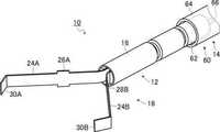
図1は、本発明のクリップ処置具の外観を表す一実施形態の部分透視斜視図、図2は、図1に示すクリップ処置具の内部の構成を表す部分断面斜視図である。 FIG. 1 is a partial perspective perspective view showing the appearance of the clip treatment tool of the present invention, and FIG. 2 is a partial cross-sectional perspective view showing the internal configuration of the clip treatment tool shown in FIG.
本実施形態において、第1方向を、2つのクリップ片の腕部が対向する方向(図9Bの紙面に垂直な方向)とし、第2方向を、第1方向および押え管の軸方向の両方に直交する方向(図9Aの紙面に垂直な方向)とする。また、クリップ処置具において、処置部の側を先端側、操作者の側を基端側とする。 In the present embodiment, the first direction is the direction in which the arms of the two clip pieces face each other (the direction perpendicular to the paper surface of FIG. 9B), and the second direction is both the first direction and the axial direction of the holding tube. The direction is orthogonal (the direction perpendicular to the paper surface of FIG. 9A). Further, in the clip treatment tool, the side of the treatment portion is the tip side, and the side of the operator is the base end side.
なお、全ての図面において、理解を容易にするために、本実施形態における各構成要素の厚さおよび長さ等の寸法は、必要に応じて実寸から適宜変更されている。 In all the drawings, in order to facilitate understanding, the dimensions such as the thickness and length of each component in the present embodiment are appropriately changed from the actual size as necessary.
図1および図2に示すクリップ処置具10は、クリップユニット12と、処置具本体14とを備えている。クリップ処置具10は、操作者による操作により、例えば、内視鏡の操作部に設けられた処置具挿入口から挿入され、患者の体内に挿入された内視鏡の挿入部の先端面に設けられた処置具導出口から突出されて処置部をクリップユニット12によって結紮する。 The
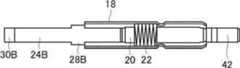
クリップユニット12は、クリップ本体16と、押え管18と、連結部材20と、付勢部材22とを備えている。 The
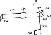
図3は、クリップ本体の外観を表す一実施形態の斜視図である。
クリップ本体16は、図3に示すように、互いに対向し、かつ開閉する第1腕部24Aおよび第2腕部24Bからなる2つの腕部と、2つの腕部24A、24Bの基端部を接続する折り返し部26とを有する。FIG. 3 is a perspective view of an embodiment showing the appearance of the clip body.
As shown in FIG. 3, the clip
2つの腕部24A、24Bと折り返し部26とは、第1腕部24Aと折り返し部26との間および第2腕部24Bと折り返し部26との間でそれぞれ折り曲げられて一体に形成されている。また、折り返し部26を第2方向から見た場合の形状は略C字状となっている。2つの腕部24A、24Bは、互いに対向し、かつ、外力が加えられていない状態において、基端側から先端側に向かうに従って互いに離間するように延在している。 The two
第1腕部24Aは、第1凸部28Aと、第1爪部30Aとを有する。
第1凸部28Aは、先端側から基端側へのクリップ本体16の移動を規制する部分であり、第1腕部24Aの延在方向の中央部において、第1腕部24Aの幅方向(第2方向)の両端部から突出するように形成されている。つまり、第1凸部28Aの幅方向の大きさ(サイズ)は、第1腕部24Aの他の部分における幅方向の大きさよりも大きくなるように形成されている。The
The first
第1爪部30Aは、第1腕部24Aの先端部に形成されている。第1爪部30Aは、第1腕部24Aの先端部が第2腕部24Bの方向に一定の角度で折り曲げられることによって形成されている。 The
第2腕部24Bは、第1腕部24Aと同様の構成であり、第1腕部24Aの第1凸部28Aおよび第1爪部30Aのそれぞれに対応する位置に形成された第2凸部28Bおよび第2爪部30Bを有する。第1爪部30Aおよび第2爪部30Bは、処置部を挟んで結紮する部分である。 The
折り返し部26の第1方向の両側面の各々の中央部には、連結部材20と係合するための矩形状の係合穴32A、32Bが形成されている。 Rectangular engaging
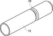
図4は、押え管の外観を表す一実施形態の斜視図である。
押え管18は、図4に示すように、筒状のものであり、基端側に設けられた被係止部34(図6参照)を有する。被係止部34は、連結部材20の係止部42が係止される部分であり、押え管18の基端側を縮径することによって形成されている。言い換えると、被係止部34は、押え管18の基端側に形成された基端面を有し、押え管18の基端面には係止孔36(図6参照)が形成されている。FIG. 4 is a perspective view of an embodiment showing the appearance of the holding tube.
As shown in FIG. 4, the
また、押え管18は、内径が両端部における内径よりも狭い絞り部38を軸方向の中央部に有する。 Further, the
押え管18は、基端側から先端側へのクリップ本体16の移動に従って2つの腕部24A、24Bを開いてクリップ本体16を露出させ、かつ、先端側から基端側へのクリップ本体16の移動に従って2つの腕部24A、24Bを閉じてその内部にクリップ本体16を収容する。 The
より詳しくは、先端側から基端側へのクリップ本体16の移動に従って、2つの腕部24A、24Bが押え管18の先端部によって互いに近接する方向に押圧されて弾性変形し、2つの腕部24A、24Bが開状態から次第に閉じて最終的に閉状態になる。一方、基端側から先端側へのクリップ本体16の移動に従って、2つの腕部24A、24Bが弾性力によって閉状態から次第に開いて最終的に開状態になる。 More specifically, as the
図5は、連結部材の外観を表す一実施形態の斜視図である。
連結部材20は、図5に示すように、連結部材本体39と、その先端側に設けられた係合部40と、基端側に設けられた係止部42とを有し、例えば、生体適合性のある各種の樹脂によって形成される。連結部材20は、2つの腕部24A、24Bが開状態の場合に、押え管18の内部に収容されている。FIG. 5 is a perspective view of an embodiment showing the appearance of the connecting member.
As shown in FIG. 5, the connecting
連結部材本体39は、円筒形状のものであり、押え管18の絞り部38の内径よりも小さい外径を持っている。 The connecting member
係合部40は、クリップ本体16の折り返し部26と係合される先端部となる部分であり、連結部材本体39から先端側に設けられる。連結部材本体39と係合部40とは一体に形成されている。係合部40は、第1係合部材44Aおよび第2係合部材44Bを有し、第1係合部材44Aおよび第2係合部材44Bは、互いに対向するように、連結部材本体39の先端部から先端側に向かって並列に延在している。また、第1係合部材44Aと第2係合部材44Bとは、第1方向に一定の間隔を空けて配置されている。第1係合部材44Aと第2係合部材44Bとの間隔は、クリップ本体16の折り返し部26の第1方向の大きさよりもわずかに広くなるになるように形成されている。 The engaging
また、第1係合部材44Aは、第2係合部材44Bに対向する内側面上に、第1係合部材44Aから第2係合部材44Bの方向に突出する第1突起部46Aを有する。同様に、第2係合部材44Bは、第1係合部材44Aに対向する内側面上に、第2係合部材44Bから第1係合部材44Aの方向に突出する第2突起部(図示省略)を有する。第1突起部46Aおよび第2突起部を第1方向から見た場合の形状は、クリップ本体16の係合穴32A、32Bを第1方向から見た場合の形状と同様の矩形状であり、その外径は、係合穴32A、32Bの内径よりもわずかに小さくなるように形成されている。 Further, the first engaging
第1係合部材44Aおよび第2係合部材44Bは、クリップ本体16の折り返し部26を第1方向の両外側から挟むように配置され、かつ、第1突起部46Aおよび第2突起部が、折り返し部26の係合穴32A、32Bにそれぞれ挿入されている。これにより、折り返し部26と係合部40とが係合されて、クリップ本体16と連結部材20とが係合されている。 The first engaging
また、連結部材20は、突出部48を先端側に有する。突出部48の外径は、連結部材20の中央部、つまり、連結部材本体39の外径よりも広く、かつ、押え管18の内径よりも狭い。本実施形態の場合、突出部48は、第1係合部材44Aおよび第2係合部材44Bの各々の先端側の外側面に設けられている。つまり、第1係合部材44Aおよび第2係合部材44Bの突出部48は、基端側の端部が角部となる基端面を有する。 Further, the connecting
係止部42は、連結部材本体39から基端側に設けられ、連結部材本体39と一体に形成されている。係止部42は、押え管18の絞り部38よりも基端側を移動可能である。係止部42は、第1係止部材50Aおよび第2係止部材50Bを有し、第1係止部材50Aおよび第2係止部材50Bは、互いに対向するように、連結部材本体39の基端部から基端側に向かって並列に延在している。また、第1係止部材50Aと第2係止部材50Bとは、第1方向に一定の間隔を空けて配置されている。 The locking
第1係止部材50Aおよび第2係止部材50Bの各々は、頂部52と、傾斜部54と、延在部56とを有する。 Each of the
第1係止部材50Aおよび第2係止部材50Bの2つの頂部52は、連結部材本体39から基端側に設けられ、先端側の端部が角部となるように形成されている。2つの頂部52の外径は、連結部材本体39の外径よりも大きく、かつ、押え管18の内径よりも小さくなるように形成されている。つまり、2つの頂部52は、先端側の端部が角部となる先端面を有する。押え管18の基端面の係止孔36の内径は、2つの頂部52に外力が加えられていない状態において、2つの頂部52の先端側の角部における外径よりもわずかに小さくなるように形成されている。 The two tops 52 of the
第1係止部材50Aおよび第2係止部材50Bの2つの傾斜部54は、2つの頂部52の各々から基端側に設けられ、先端側から基端側に向かって次第に縮径するように形成されている。 The two
第1係止部材50Aおよび第2係止部材50Bの2つの延在部56は、傾斜部54からさらに基端側に向かって直線状に延在するように形成されている。つまり、2つの頂部52、2つの傾斜部54および2つの延在部56は、互いに対向するように並列に延在している。2つの延在部56の外径は、2つの傾斜部54の最も基端側の端部における外径と略同一であり、押え管18の基端面の係止孔36の内径よりも小さくなるように形成されている。 The two extending
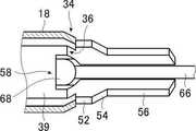
図6は、連結部材の基端側の構成を表す一実施形態の部分断面図である。
連結部材本体39は、図6に示すように、その内部に形成された収容部58を有する。収容部58は、操作ワイヤ66の先端部が着脱可能に係止される部分であり、連結部材20の2つの頂部52よりも先端側の連結部材20の内部、つまり、連結部材本体39の内部に形成されている。収容部58は、半円筒形状の空間であり、連結部材20の第1係止部材50Aと第2係止部材50Bとの間の空間に対応する連結部材本体39の内部の位置において第2方向に延在し、かつ、湾曲面が基端側、つまり、第1係止部材50Aと第2係止部材50Bとの間の空間の側を向くように形成されている。収容部58の基端側には、第1係止部材50Aと第2係止部材50Bとの間の空間とつながる開口部が形成されている。収容部58の開口部の第1方向の大きさは、第1係止部材50Aと第2係止部材50Bとの間隔と略同じである。FIG. 6 is a partial cross-sectional view of an embodiment showing the configuration of the base end side of the connecting member.
As shown in FIG. 6, the connecting member
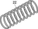
図7は、付勢部材の外観を表す一実施形態の斜視図である。
付勢部材22は、押え管18の内部に収容されている。本実施形態の場合、付勢部材22は、図7に示すように、圧縮バネを有する。
付勢部材22は、連結部材20の連結部材本体39の外側面を覆うように設けられ、連結部材20の2つの突出部48と押え管18の絞り部38との間に配置されている。つまり、付勢部材22の先端側の端部は、2つの突出部48の基端面に当接し、付勢部材22の基端側の端部は、押え管18の絞り部38の先端側の端面に当接している。FIG. 7 is a perspective view of an embodiment showing the appearance of the urging member.
The urging
The urging
押え管18に対する先端側から基端側への連結部材20の移動に従って、付勢部材22は次第に圧縮されて弾性変形する。一方、押え管18に対する基端側から先端側への連結部材20の移動に従って、付勢部材22は、伸長して、その弾性力によって連結部材20を押え管18に対して基端側から先端側に付勢し、連結部材20およびクリップ本体16を押え管18に対して基端側から先端側に移動させる。 As the connecting
クリップユニット12を構成するクリップ本体16、押え管18および付勢部材22は、例えば、ステンレス鋼、チタン、コバルトクロム合金等の材料から形成される。従って、クリップユニット12を患者の体内に留置した後も、その患者はMRI(核磁気共鳴画像法)を受診することが可能である。 The
次に、処置具本体14は、挿入部60と、図示していない操作部とを備えている。 Next, the treatment tool
挿入部60は、コイルシース62と、チューブシース64と、操作ワイヤ66とを備えている。 The
コイルシース62およびチューブシース64は、可撓性のある管状のものであり、例えば、PTFE(ポリテトラフルオロエチレン)等のフッ素樹脂、または、HDPE(高密度ポリエチレン)等の樹脂材料によって形成される。コイルシース62は、チューブシース64の内部に挿通されている。コイルシース62の先端部の内径は、押え管18の基端部の外径よりもわずかに大きくなるように形成されている。押え管18の基端部がコイルシース62の先端部に嵌合され、押え管18がコイルシース62に着脱自在に装着されている。 The
続いて、操作ワイヤ66は、例えば、金属製の単線または縒り線によって形成される。操作ワイヤ66は、コイルシース62の軸方向に沿って移動可能なように、コイルシース62の内部に挿通されている。 Subsequently, the
操作ワイヤ66は、コイルシース62内を先端側または基端側に移動する。つまり、操作ワイヤ66を基端側から先端側に押し出す、または、操作ワイヤ66を先端側から基端側に引くことができる。 The
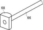
図8は、操作ワイヤの先端側の外観を表す一実施形態の斜視図である。
操作ワイヤ66は、図8に示すように、その先端側に設けられたワイヤ留め具68を有する。ワイヤ留め具68は、連結部材本体39の収容部58と略同一の半円筒形状であり、その外径は、収容部58の内径よりもわずかに小さくなるように形成されている。半円筒形状のワイヤ留め具68の湾曲面の中央部には、操作ワイヤ66の先端側が固定されている。FIG. 8 is a perspective view of an embodiment showing the appearance of the tip end side of the operation wire.
As shown in FIG. 8, the
ワイヤ留め具68は、図6に示すように、収容部58内に収容されている。操作ワイヤ66の直径は、連結部材20の第1係止部材50Aと第2係止部材50Bとの間隔よりも小さく、操作ワイヤ66は、第1係止部材50Aと第2係止部材50Bとの間に挿通されている。これにより、連結部材本体39とワイヤ留め具68とが係止され、連結部材20と操作ワイヤ66とが着脱自在に係止されている。 As shown in FIG. 6, the
前述のように、連結部材20の先端部がクリップ本体16の折り返し部26と係合され、連結部材20と操作ワイヤ66とが着脱自在に係止されて、連結部材20によってクリップ本体16と操作ワイヤ66とが連結されている。 As described above, the tip of the connecting
続いて、処置具本体14の操作部は、図示していない操作部本体およびスライダ等を有する。
操作部本体の先端部は、コイルシース62の基端部に取付けられている。
スライダは、コイルシース62に対して操作ワイヤ66を先端側または基端側に移動させる部分であり、操作部本体に対して先端側または基端側にスライド可能に設けられ、スライダの先端部には、操作ワイヤ66の基端部が固定されている。Subsequently, the operation unit of the treatment tool
The tip of the operation unit body is attached to the base end of the
The slider is a portion that moves the
操作者によるクリップ処置具10の操作部の操作により、スライダが操作部本体に対して先端側または基端側へ移動されると、操作ワイヤ66が先端側または基端側に移動する。また、基端側から先端側への操作ワイヤ66の移動に従って、連結部材20およびクリップ本体16が基端側から先端側に移動し、先端側から基端側への操作ワイヤ66の移動に従って、連結部材20およびクリップ本体16が先端側から基端側に移動する。 When the slider is moved to the tip end side or the proximal end side with respect to the main body of the operation portion by the operation of the operation portion of the
次に、クリップ処置具10の動作を説明する。
まず、クリップユニット12によって処置部を結紮する場合の動作を説明する。以下の説明では、図示していない内視鏡の挿入部が既に患者の体内に挿入されているものとする。Next, the operation of the
First, the operation when the treatment portion is ligated by the
まず、操作者による操作により、図示していない内視鏡の処置具挿入口からクリップ処置具10の挿入部60が挿入され、クリップ処置具10の挿入部60の先端部、より正確には、クリップユニット12の先端部が内視鏡の処置具導出口から突出される。 First, by an operation by the operator, the
続いて、操作者によるクリップ処置具10の操作部の操作により、操作ワイヤ66が基端側から先端側に移動される。 Subsequently, the
基端側から先端側への操作ワイヤ66の移動に従って、付勢部材22が伸長し、連結部材20およびクリップ本体16が付勢部材22によって付勢されて基端側から先端側に移動する。これにより、図9Aおよび図9Bに示すように、クリップ本体16の2つの腕部24A、24Bは開状態となる。 As the
続いて、操作者による操作により、挿入部60が基端側から先端側に移動され、開状態の2つの腕部24A、24Bの先端部が処置部に押し当てられる。 Subsequently, the
続いて、開状態の2つの腕部24A、24Bの先端部が処置部に押し当てられた状態において、操作者によるクリップ処置具10の操作部の操作により、操作ワイヤ66が先端側から基端側に移動される。 Subsequently, in a state where the tips of the two
先端側から基端側への操作ワイヤ66の移動に従って、付勢部材22が圧縮される。連結部材20およびクリップ本体16は、付勢部材22による付勢力に逆らって、先端側から基端側に移動し、かつ、2つの腕部24A、24Bが押え管18の先端部によって互いに近接する方向に押圧されて弾性変形して、2つの腕部24A、24Bは開状態から次第に閉じる。 The urging
連結部材20が押え管18にロックされる前の状態においては、先端側または基端側への連結部材20の移動に従って、2つの腕部24A、24Bは開閉可能である。 In the state before the connecting
先端側から基端側への連結部材20の移動に従って、付勢部材22が圧縮される。クリップ本体16は先端側から基端側に移動し、かつ、2つの腕部24A、24Bは、押え管18の先端部によって互いに近接する方向に押圧されて弾性変形し、開状態(全開状態)から次第に閉じて最終的に閉状態(全閉状態)になる。また、先端側から基端側への連結部材20の移動に従って、連結部材20の係止部42が先端側から基端側に移動し、押え管18の係止孔36を通過して押え管18の基端面から突出する。 The urging
一方、基端側から先端側への連結部材20の移動に従って、付勢部材22が伸長し、連結部材20は、付勢部材22によって付勢されて基端側から先端側にさらに移動する。クリップ本体16は基端側から先端側に移動し、かつ、2つの腕部24A、24Bは、弾性力によって閉状態から次第に開いて最終的に開状態になる。また、基端側から先端側への連結部材20の移動に従って、連結部材20の係止部42が基端側から先端側に移動し、押え管18の係止孔36を通過して押え管18内に収容される。 On the other hand, as the connecting
このように、連結部材20が押え管18にロックされる前の状態においては、2つの腕部24A、24Bを開閉し、処置部を2つの腕部24A、24Bの第1爪部30Aおよび第2爪部30Bによって掴み直すことができるため、目的とする処置部を正確に掴むことができる。 As described above, in the state before the connecting
続いて、2つの腕部24A、24Bの第1爪部30Aおよび第2爪部30Bによって処置部が掴まれた状態において、操作ワイヤ66が先端側から基端側にさらに移動される。 Subsequently, the
これに従って、付勢部材22がさらに圧縮され、付勢部材22による付勢力に逆らって、連結部材20およびクリップ本体16が先端側から基端側にさらに移動して、2つの腕部24A、24Bはさらに閉じる。 Accordingly, the urging
先端側から基端側への連結部材20のさらなる移動に従って、連結部材20の係止部42が先端側から基端側にさらに移動し、係止部42の延在部56が押え管18の係止孔36を通過して押え管18の基端面から突出する。 As the connecting
先端側から基端側への係止部42のさらなる移動に従って、連結部材20の2つの傾斜部54が係止孔36の先端部によって互いに近接する方向に押圧されて、係止部42の第1係合部材44Aおよび第2係合部材44Bが互いに近接する方向に撓む。これにより、2つの傾斜部54、さらには、2つの頂部52および2つの延在部56が縮径して係止孔36を通過する。 As the locking
係止部42が先端側または基端側に移動する場合、2つの傾斜部54の傾斜面(外側面)と押え管18の係止孔36の先端部の内周面とが接触し、2つの傾斜部54の傾斜面は、係止孔36の先端部の内周面に沿って摺動する。2つの傾斜部54の傾斜面は、係止部42が係止孔36の先端部の内周面に沿って摺動する場合に、係止部42と係止孔36との間の摩擦抵抗を軽減し、係止部42が係止孔36に対して先端側または基端側に移動しやすくなるように作用する。 When the locking
先端側から基端側への係止部42のさらなる移動に従って、2つの頂部52の先端側の角部が係止孔36を越える位置まで移動し、縮径した2つの頂部52が弾性力によって互いに離間する。これにより、2つの頂部52の先端側の角部における外径が係止孔36の内径よりも大きくなり、2つの頂部52の先端側の角部が被係止部34の基端面に係止される。つまり、係止部42が被係止部34に係止される。 As the locking
また、2つの頂部52の先端側の角部が係止孔36を越える位置まで移動すると、2つの腕部24A、24Bは、図10Aおよび図10Bに示すように、閉状態となる。 Further, when the corner portion on the tip side of the two
これにより、連結部材20は、2つの腕部24A、24Bが閉状態において押え管18にロックされ、2つの腕部24A、24Bの第1爪部30Aおよび第2爪部30Bによって処置部が結紮される。 As a result, the connecting
続いて、連結部材20が押え管18にロックされた状態、つまり、2つの腕部24A、24Bの第1爪部30Aおよび第2爪部30Bによって処置部が結紮された状態において、操作ワイヤ66が先端側から基端側にさらに移動される。 Subsequently, in a state where the connecting
これに従って、連結部材20およびクリップ本体16が先端側から基端側にさらに移動し、2つの腕部24A、24Bの第1凸部28Aおよび第2凸部28Bの基端側の端部が押え管18の先端部に当接する。これにより、先端側から基端側への連結部材20およびクリップ本体16の移動が規制される。 According to this, the connecting
続いて、連結部材20が押え管18にロックされ、かつ、先端側から基端側への連結部材20およびクリップ本体16の移動が規制された状態において、操作ワイヤ66が先端側から基端側にさらに移動される。 Subsequently, in a state where the connecting
先端側から基端側への操作ワイヤ66の移動に従って、連結部材20の2つの頂部52がワイヤ留め具68の基端側の端部、つまり、湾曲面によって第1方向に押し広げられて互いに離間し、ワイヤ留め具68が連結部材20の収容部58から外れる。これにより、連結部材20と操作ワイヤ66とが分離される。 As the
続いて、連結部材20と操作ワイヤ66とが分離された状態において、操作ワイヤ66が基端側から先端側に移動される。 Subsequently, in a state where the connecting
基端側から先端側への操作ワイヤ66の移動に従って、ワイヤ留め具68が基端側から先端側に移動し、ワイヤ留め具68の先端部が連結部材20の係止部42の基端部に当接する。 As the
基端側から先端側への操作ワイヤ66のさらなる移動に従って、ワイヤ留め具68によって連結部材20の係止部42、つまり、クリップ本体16が先端側に押し出されて、図11Aおよび図11Bに示すように、クリップユニット12がコイルシース62から分離される。これにより、クリップユニット12によって処置部が結紮された状態において、クリップユニット12が処置部に留置される。 As the
その後、操作者による操作により、クリップ処置具10の挿入部60が内視鏡の内部に挿入されたままの状態において患者の体内から内視鏡の挿入部が引き抜かれて取り出される。なお、複数の処置部を結紮する場合には前述の動作が繰り返し行われる。 Then, by the operation by the operator, the insertion portion of the endoscope is pulled out from the patient's body and taken out while the
次に、処置部からクリップユニット12を取り外す場合の動作を説明する。
まず、操作者による操作部の操作により把持部が開閉する把持鉗子等の把持部材を用いてクリップユニット12を取り外す場合の動作を説明する。Next, the operation when the
First, the operation when the
図12は、把持鉗子の先端部分の構成を表す一実施形態の側面図である。図12に示す把持鉗子70は、把持部72と、挿入部74と、図示していない操作部とを備えている。把持部72は、挿入部74の先端部に取り付けられ、図示していない操作部は、挿入部74の基端部に取り付けられている。 FIG. 12 is a side view of an embodiment showing the configuration of the tip portion of the grasping forceps. The gripping
把持部72は、一対の爪部材76A、76Bを有する。爪部材76A、76Bは、操作者による操作部の操作により開閉する。爪部材76A、76Bは、基端側から先端側に向けて延び、その把持面が閉状態の場合に、互いに対向するように配置されている。 The
挿入部74は、シース78と、操作ワイヤ80とを備えている。
操作ワイヤ80は、シース78内に進退可能に挿通されている。把持部72は、シース78の先端部に取り付けられ、把持部72の爪部材76A、76Bの基端部には、操作ワイヤ80の先端部が固定されている。The
The
操作者による操作部の操作により、操作ワイヤ80が先端側から基端側に移動すると、一対の爪部材76A、76Bが開状態(非把持状態)から次第に閉じて最終的に閉状態(把持状態)になる。一方、操作ワイヤ80が基端側から先端側に移動すると、一対の爪部材76A、76Bが閉状態から次第に開いて最終的に開状態になる。 When the
クリップユニット12を取り外す場合、まず、操作者による操作により、図示していない内視鏡の処置具挿入口から把持鉗子70の挿入部74が挿入され、把持鉗子70の挿入部74の先端部、より正確には、把持鉗子70の先端部の把持部72が内視鏡の処置具導出口から突出される。 When removing the
続いて、連結部材20と操作ワイヤ66とが分離された状態、つまり、クリップユニット12が処置部に留置された状態において、操作者による把持鉗子70の操作部の操作により、把持鉗子70の把持部72の爪部材76A、76Bが開状態とされる。続いて、開状態の把持部72の爪部材76A、76Bが次第に閉じられ、図13の矢印によって示すように、連結部材20の係止部42の第1係止部材50Aおよび第2係止部材50Bが、把持鉗子70の把持部72の爪部材76A、76Bによって、第1方向、つまり、第1係止部材50Aおよび第2係止部材50Bが対向する方向の両外側から挟まれて押圧される。これにより、連結部材20の2つの頂部52が両外側から押圧される。 Subsequently, in a state where the connecting
2つの頂部52が両外側から押圧されて互いに近接すると、2つの頂部52の先端側の角部における外径が係止孔36の内径よりも小さくなり、連結部材20と押え管18とのロックが解除される。ロックが解除されると、図14に示すように、連結部材20が付勢部材22によって付勢されて基端側から先端側に移動する。基端側から先端側への連結部材20の移動に従って、図15に示すように、クリップ本体16が基端側から先端側に移動し、かつ、2つの腕部24A、24Bが弾性力によって閉状態から次第に開いて最終的に開状態に戻る。これにより、クリップユニット12が処置部から取り外される。 When the two tops 52 are pressed from both outer sides and come close to each other, the outer diameter at the corner portion on the tip side of the two tops 52 becomes smaller than the inner diameter of the locking
その後、操作者による操作により、把持鉗子70の挿入部74が内視鏡の内部に挿入されたままの状態において患者の体内から内視鏡の挿入部が引き抜かれて取り出される。例えば、把持鉗子70の把持部72の爪部材76A、76Bによってクリップユニット12の任意の箇所が挟持された状態において、患者の体内から内視鏡の挿入部が引き抜かれて、処置部から取り外されたクリップユニット12も同時に患者の体外に取り出される。なお、複数のクリップユニット12を処置部から取り外す場合には前述の動作が繰り返し行われる。 Then, by an operation by the operator, the insertion portion of the endoscope is pulled out from the patient's body and taken out while the
次に、操作者による操作部の操作によりループの径が拡縮するスネア部材を用いてクリップユニット12を取り外す場合の動作を説明する。 Next, the operation when the
図16は、スネア部材の先端部分の構成を表す一実施形態の側面図である。図16に示すスネア部材82は、ループ部84と、挿入部86と、図示していない操作部とを備えている。ループ部84は、後述する挿入部86の内部に挿通される操作ワイヤ90の先端部に取り付けられ、図示していない操作部は、挿入部86の基端部に取り付けられている。FIG.16 is a side view of an embodiment showing the configuration of the tip portion of the snare member. The
ループ部84は、ワイヤを折り曲げることにより形成されている。ワイヤの折り曲げ部が先端側に向けられている。ループ部84は、操作者による操作部の操作により、そのループの径が拡縮する。 The
挿入部86は、シース88と、操作ワイヤ90とを備えている。
操作ワイヤ90は、シース内に進退可能に挿通されている。ループ部84のワイヤの両端部は、シース88の先端部に取り付けられ、操作ワイヤ90の先端部に固定されている。The
The
操作者による操作部の操作により、操作ワイヤ90が先端側から基端側に移動すると、ループ部84がシース88内に収容されてループ部84のループの径が縮む。一方、操作ワイヤ90が基端側から先端側に移動すると、ループ部84がシース88の先端部から突出されてループ部84のループの径が拡がる。 When the
クリップユニット12を取り外す場合、まず、操作者による操作により、図示していない内視鏡の処置具挿入口からスネア部材82の挿入部86が挿入され、スネア部材82の挿入部86の先端部、より正確には、スネア部材82の先端部のループ部84が内視鏡の処置具導出口から突出される。 When removing the
続いて、連結部材20と操作ワイヤ66とが分離された状態、つまり、クリップユニット12が処置部に留置された状態において、操作者によるスネア部材82の操作部の操作により、スネア部材82のループ部84のループの径が拡大される。続いて、ループ部84の拡大されたループの径が次第に縮小され、図13の矢印によって示すように、連結部材20の係止部42の第1係止部材50Aおよび第2係止部材50Bが、ループ部84によって締め付けられて、第1方向、つまり、第1係止部材50Aおよび第2係止部材50Bが対向する方向の両外側から押圧される。これにより、連結部材20の2つの頂部52が両外側から押圧される。 Subsequently, in a state where the connecting
2つの頂部52が両外側から押圧されて互いに近接すると、2つの頂部52の先端側の角部における外径が係止孔36の内径よりも小さくなり、連結部材20と押え管18とのロックが解除される。ロックが解除されると、図14に示すように、連結部材20が付勢部材22によって付勢されて基端側から先端側に移動する。基端側から先端側への連結部材20の移動に従って、図15に示すように、クリップ本体16が基端側から先端側に移動し、かつ、2つの腕部24A、24Bが弾性力によって閉状態から次第に開いて最終的に開状態に戻る。これにより、クリップユニット12が処置部から取り外される。 When the two tops 52 are pressed from both outer sides and come close to each other, the outer diameter at the corner portion on the tip side of the two tops 52 becomes smaller than the inner diameter of the locking
その後、操作者による操作により、スネア部材82の挿入部86が内視鏡の内部に挿入されたままの状態において患者の体内から内視鏡の挿入部が引き抜かれて取り出される。例えば、スネア部材82のループ部84によってクリップユニット12の任意の箇所が締め付けられた状態において、患者の体内から内視鏡の挿入部が引き抜かれて、処置部から取り外されたクリップユニット12も同時に患者の体外に取り出される。なお、複数のクリップユニット12を処置部から取り外す場合には前述の動作が繰り返し行われる。 Then, by an operation by the operator, the insertion portion of the endoscope is pulled out from the patient's body and taken out while the
クリップ処置具10においては、クリップユニット12によって処置部が結紮されるまでの間は、処置部を2つの腕部24A、24Bで掴み直すことができ、クリップユニット12によって処置部が結紮された後は、連結部材20と押え管18とがロックされているため、クリップユニット12によって処置部が結紮された状態を確実に保持することができる。また、クリップユニット12が処置部に留置された後は、連結部材20と押え管18とのロックを任意のタイミングで解除してクリップユニット12を処置部から取り外すことができる。 In the
なお、クリップ本体16の第1凸部28Aおよび第2凸部28Bは必須の構成要素ではない。先端側から基端側へのクリップ本体16の移動は、第1凸部28Aおよび第2凸部28Bがない場合でも、付勢部材22が最大限に圧縮される位置までに規制される。 The first
クリップ本体16の折り返し部26の形状、係合穴32A、32Bおよび連結部材20の第1突起部46Aおよび第2突起部の形状は、折り返し部26と連結部材20の係合部40とを係合することができれば、どのような形状であってもよい。 The shape of the folded-
押え管18の被係止部34の基端面は、上記実施形態では、押え管18の基端側を縮径して傾斜面となるように形成されているが、これに限らず、押え管18の基端側の内周面から中心軸に向かって延在するように形成してもよい。 In the above embodiment, the base end surface of the locked
連結部材20の突出部48は、上記実施形態では、第1係合部材44Aおよび第2係合部材44Bの各々の先端側の外側面に設けられているが、これに限定されず、付勢部材22の先端側の端部に当接する基端面を持っていればよい。突出部48は、例えば、第1係合部材44Aおよび第2係合部材44Bの一方の先端側の外側面に設けられていてもよいし、連結部材本体39の先端側の外側面に設けられていてもよい。 In the above embodiment, the protruding
連結部材20の収容部58およびワイヤ留め具68の形状は、連結部材本体39とワイヤ留め具68とを係止して連結部材20と操作ワイヤ66とを係止し、かつ、ワイヤ留め具68を収容部58から外すことができれば、どのような形状であってもよい。 The shape of the
クリップユニット12を取り外す場合、連結部材20の係止部42の第1係止部材50Aおよび第2係止部材50Bを両外側から押圧して2つの頂部52を両外側から押圧するが、例えば、2つの延在部56または2つの傾斜部54を両外側から押圧することによって2つの頂部52を両外側から押圧してもよいし、2つの頂部52を両外側から直接押圧してもよい。 When removing the
以上、本発明について詳細に説明したが、本発明は上記実施形態に限定されず、本発明の主旨を逸脱しない範囲において、種々の改良や変更をしてもよいのはもちろんである。 Although the present invention has been described in detail above, the present invention is not limited to the above-described embodiment, and it goes without saying that various improvements and changes may be made without departing from the gist of the present invention.
10 クリップ処置具
12 クリップユニット
14 処置具本体
16 クリップ本体
18 押え管
20 連結部材
22 付勢部材
24A 第1腕部
24B 第2腕部
26 折り返し部
28A 第1凸部
28B 第2凸部
30A 第1爪部
30B 第2爪部
32A、32B 係合穴
34 被係止部
36 係止孔
38 絞り部
39 連結部材本体
40 係合部
42 係止部
44A 第1係合部材
44B 第2係合部材
46A 第1突起部
48 突出部
50A 第1係止部材
50B 第2係止部材
52 頂部
54 傾斜部
56 延在部
58 収容部
60、74,86挿入部
62 コイルシース
64 チューブシース
66、80,90操作ワイヤ
68 ワイヤ留め具
70 把持鉗子
72 把持部
76A、76B 爪部材
78、88 シース
82 スネア部材
84 ループ部10
Claims (6)
Translated fromJapanese基端側から先端側への前記クリップ本体の移動に従って前記2つの腕部を開いて前記クリップ本体を露出させ、かつ、先端側から基端側への前記クリップ本体の移動に従って前記2つの腕部を閉じて内部に前記クリップ本体を収容する筒状の押え管と、
前記クリップ本体の前記折り返し部と係合される先端部と、操作ワイヤの先端部が着脱可能に係止される基端部とを有し、前記クリップ本体と前記操作ワイヤとを連結する連結部材と、
前記押え管の内部に収容され、前記連結部材を前記押え管に対して基端側から先端側に付勢する付勢部材とを備え、
前記押え管は、前記押え管の基端側に設けられた被係止部を有し、前記連結部材は、前記連結部材の基端側に設けられた係止部を有し、
前記係止部は、互いに対向するように先端側から基端側に向かって延在する2つの係止部材を有し、
先端側から基端側への前記操作ワイヤの移動に従って、前記連結部材が先端側から基端側に移動し、前記係止部が前記被係止部に係止されて、前記連結部材が前記押え管にロックされ、
前記2つの係止部材が対向する方向の両外側から押圧されると、前記係止部が前記被係止部から外れて、前記連結部材と前記押え管とのロックが解除されるクリップ処置具。A clip body having two arms that face each other and open and close, and a folded portion that connects the base ends of the two arms.
The two arms are opened according to the movement of the clip body from the base end side to the tip end side to expose the clip body, and the two arms are exposed according to the movement of the clip body from the tip end side to the base end side. With a tubular holding tube that closes and houses the clip body inside,
A connecting member having a tip end portion engaged with the folded-back portion of the clip body and a base end portion to which the tip end portion of the operation wire is detachably locked, and connecting the clip body and the operation wire. When,
A urging member housed inside the holding pipe and urging the connecting member from the proximal end side to the distal end side with respect to the holding pipe.
The holding pipe has a locked portion provided on the base end side of the holding pipe, and the connecting member has a locking portion provided on the base end side of the connecting member.
The locking portion has two locking members extending from the distal end side toward the proximal end side so as to face each other.
According to the movement of the operation wire from the tip end side to the proximal end side, the connecting member moves from the distal end side to the proximal end side, the locking portion is locked to the locked portion, and the connecting member is said. Locked to the presser tube,
When thetwo locking members are pressed fromboth sidesin the direction opposite the locking portion is disengaged from the locked portion, clipping the locking of saidpresser tube and the connecting member is released Ingredients.
前記被係止部は、前記押え管の基端側に形成された基端面を有し、前記押え管の前記基端面には、前記2つの頂部の先端側の前記角部における外径よりも小さい内径を持つ係止孔が形成され、
先端側から基端側への前記連結部材の移動に従って、前記2つの傾斜部が前記係止孔の先端部によって互いに近接する方向に押圧されて前記係止孔を通過し、前記2つの頂部の前記角部が前記被係止部の前記係止孔を越える位置まで移動し、前記2つの頂部が弾性力によって互いに離間して前記2つの頂部の前記角部が前記被係止部の基端面に係止され、前記連結部材は、前記2つの腕部が前記閉状態において前記押え管にロックされる請求項2に記載のクリップ処置具。The locking portion has two tops formed so that the end on the tip side is a corner portion, and two inclined portions provided on the base end side from each of the two tops. The two tops and the two slopes extend so as to face each other.
The locked portion has a proximal end surface formed on the proximal end side of the holding tube, and the proximal end surface of the pressing tube has a diameter larger than the outer diameter at the corner portion on the distal end side of the two tops. A locking hole with a small inner diameter is formed,
As the connecting member moves from the tip end side to the base end side, the two inclined portions are pressed by the tip portions of the locking holes in a direction close to each other to pass through the locking holes, and the two tops of the two tops are pressed. The corner portion moves to a position beyond the locking hole of the locked portion, the two top portions are separated from each other by an elastic force, and the corner portion of the two top portions is the base end surface of the locked portion. The clip treatment tool according to claim 2, wherein the connecting member is locked to the holding tube in the closed state.
前記連結部材が前記押え管にロックされた状態において、先端側から基端側への前記操作ワイヤの移動に従って、前記2つの頂部が前記ワイヤ留め具の基端側の端部によって押し広げられて互いに離間し、前記ワイヤ留め具が前記収容部から外れて、前記連結部材と前記操作ワイヤとが分離される請求項3に記載のクリップ処置具。The connecting member has an accommodating portion formed inside the connecting member on the tip side of the two tops, and the operating wire is provided on the tip end side of the operating wire and is provided in the accommodating portion. Has housed wire fasteners,
In a state where the connecting member is locked to the holding pipe, the two tops are pushed open by the base end side of the wire fastener as the operation wire moves from the tip end side to the base end side. The clip treatment tool according to claim 3, wherein the wire fasteners are separated from each other, the wire fastener is disengaged from the housing portion, and the connecting member and the operation wire are separated from each other.
前記付勢部材は、前記突出部と前記絞り部との間に配置され、前記係止部は、前記絞り部よりも基端側を移動可能である請求項1ないし5のいずれか一項に記載のクリップ処置具。The holding pipe has a throttle portion having an inner diameter narrower than the inner diameter at both ends at the central portion in the axial direction, and the connecting member has a protruding portion having an outer diameter wider than the outer diameter at the central portion on the tip side. ,
The urging member is arranged between the protruding portion and the throttle portion, and the locking portion is movable on the proximal end side of the throttle portion according to any one of claims 1 to 5. The clip treatment tool described.
Applications Claiming Priority (3)
| Application Number | Priority Date | Filing Date | Title |
|---|---|---|---|
| JP2017121530 | 2017-06-21 | ||
| JP2017121530 | 2017-06-21 | ||
| PCT/JP2018/015150WO2018235401A1 (en) | 2017-06-21 | 2018-04-11 | Clip treatment tool |
Publications (2)
| Publication Number | Publication Date |
|---|---|
| JPWO2018235401A1 JPWO2018235401A1 (en) | 2020-03-19 |
| JP6896855B2true JP6896855B2 (en) | 2021-06-30 |
Family
ID=64737046
Family Applications (1)
| Application Number | Title | Priority Date | Filing Date |
|---|---|---|---|
| JP2019525139AActiveJP6896855B2 (en) | 2017-06-21 | 2018-04-11 | Clip treatment tool |
Country Status (5)
| Country | Link |
|---|---|
| US (1) | US11141167B2 (en) |
| EP (1) | EP3643254B1 (en) |
| JP (1) | JP6896855B2 (en) |
| CN (1) | CN110769764B (en) |
| WO (1) | WO2018235401A1 (en) |
Families Citing this family (6)
| Publication number | Priority date | Publication date | Assignee | Title |
|---|---|---|---|---|
| EP3643254B1 (en)* | 2017-06-21 | 2022-06-22 | FUJIFILM Corporation | Clipping tool |
| JP7201703B2 (en)* | 2018-11-09 | 2023-01-10 | オリンパス株式会社 | endoscope clip |
| WO2020141345A1 (en)* | 2019-01-03 | 2020-07-09 | Olympus Corporation | A clipping device for large defects, perforations and fistulas |
| EP4505967A3 (en)* | 2019-05-28 | 2025-05-07 | Boston Scientific Scimed Inc. | Hemostasis clip deployment |
| WO2021210059A1 (en)* | 2020-04-14 | 2021-10-21 | オリンパス株式会社 | Clip device and method for connecting clip unit to actuator |
| CN115996683A (en)* | 2020-08-06 | 2023-04-21 | 奥林巴斯医疗株式会社 | Clamp retaining device and clamp |
Family Cites Families (20)
| Publication number | Priority date | Publication date | Assignee | Title |
|---|---|---|---|---|
| JPS4921173B1 (en) | 1970-01-29 | 1974-05-30 | ||
| FR2381594A1 (en) | 1977-02-24 | 1978-09-22 | Centre Techn Ind Mecanique | ELECTROCHEMICAL MACHINING PROCESS OF POLYPHASIC ALLOYS |
| JPS53135292A (en) | 1977-04-28 | 1978-11-25 | Sharp Corp | Structure and production of variable stripe width semiconductor laser element |
| JPH0426091Y2 (en)* | 1988-06-24 | 1992-06-23 | ||
| JPH026011A (en) | 1988-06-24 | 1990-01-10 | Kobe Steel Ltd | Die for drawing |
| JP3776529B2 (en) | 1996-02-29 | 2006-05-17 | オリンパス株式会社 | Clip device |
| US6991634B2 (en)* | 2001-05-23 | 2006-01-31 | Pentax Corporation | Clip device of endoscope |
| US7727247B2 (en)* | 2002-08-21 | 2010-06-01 | Olympus Corporation | Living tissue ligation device |
| EP1670365B1 (en) | 2003-09-30 | 2018-12-05 | Boston Scientific Scimed, Inc. | Apparatus for deployment of a hemostatic clip |
| JP5175833B2 (en)* | 2006-03-10 | 2013-04-03 | クック メディカル テクノロジーズ エルエルシー | Medical device capable of drawing target tissue into clip arm housing chamber |
| JP4116049B2 (en)* | 2006-07-25 | 2008-07-09 | オリンパスメディカルシステムズ株式会社 | Biological tissue clip device |
| JP4910879B2 (en) | 2007-05-22 | 2012-04-04 | 住友ベークライト株式会社 | Medical clip device, its elastic clip unit and flexible tube unit |
| BR112013008763B1 (en)* | 2010-10-11 | 2021-02-17 | Cook Medical Technologies LLC. | medical device for engaging a tissue |
| KR101201083B1 (en)* | 2011-06-15 | 2012-11-13 | 국립암센터 | Medical Multiple Clips, Clip Gun applying the same, Clipping Method using the same |
| WO2013067662A1 (en)* | 2011-11-11 | 2013-05-16 | Zhu Jian | Clamping or ligating device |
| CN104869917B (en)* | 2013-05-07 | 2017-10-10 | 奥林巴斯株式会社 | Endoscopic treatment device |
| JP5750619B2 (en)* | 2013-05-07 | 2015-07-22 | オリンパス株式会社 | Clip unit |
| CN103989500B (en) | 2014-05-23 | 2015-11-18 | 南京微创医学科技有限公司 | A kind of hemostatic clamp |
| CN110461254B (en)* | 2017-03-22 | 2022-09-16 | 富士胶片株式会社 | Clamp treatment tool |
| EP3643254B1 (en)* | 2017-06-21 | 2022-06-22 | FUJIFILM Corporation | Clipping tool |
- 2018
- 2018-04-11EPEP18820408.5Apatent/EP3643254B1/enactiveActive
- 2018-04-11JPJP2019525139Apatent/JP6896855B2/enactiveActive
- 2018-04-11WOPCT/JP2018/015150patent/WO2018235401A1/ennot_activeCeased
- 2018-04-11CNCN201880039630.6Apatent/CN110769764B/enactiveActive
- 2019
- 2019-12-12USUS16/712,929patent/US11141167B2/enactiveActive
Also Published As
| Publication number | Publication date |
|---|---|
| US11141167B2 (en) | 2021-10-12 |
| US20200113572A1 (en) | 2020-04-16 |
| CN110769764B (en) | 2022-09-16 |
| JPWO2018235401A1 (en) | 2020-03-19 |
| WO2018235401A1 (en) | 2018-12-27 |
| EP3643254B1 (en) | 2022-06-22 |
| EP3643254A1 (en) | 2020-04-29 |
| CN110769764A (en) | 2020-02-07 |
| EP3643254A4 (en) | 2020-04-29 |
Similar Documents
| Publication | Publication Date | Title |
|---|---|---|
| JP6896855B2 (en) | Clip treatment tool | |
| JP6815506B2 (en) | Clip treatment tool | |
| JP6768926B2 (en) | Clip treatment tool | |
| JP4354804B2 (en) | Surgical clip | |
| CN107072671B (en) | Treatment tool for endoscope | |
| JP6858258B2 (en) | Clip treatment tool | |
| US10842351B2 (en) | Endoscope treatment tool | |
| JP5848827B2 (en) | Manual surgical ligation clip applier | |
| JP2006510457A (en) | Surgical staples / clips and appliers | |
| AU2002320128A1 (en) | Surgical clip | |
| JP7303217B2 (en) | Ligating device and applicator | |
| US20210290244A1 (en) | Cartridge, clip system, and method of mounting clip | |
| JP4475229B2 (en) | Endoscope clip | |
| WO1997047245A1 (en) | Ligating instrument | |
| JPH012639A (en) | surgical clip attachment device |
Legal Events
| Date | Code | Title | Description |
|---|---|---|---|
| A621 | Written request for application examination | Free format text:JAPANESE INTERMEDIATE CODE: A621 Effective date:20191115 | |
| A131 | Notification of reasons for refusal | Free format text:JAPANESE INTERMEDIATE CODE: A131 Effective date:20201013 | |
| A521 | Request for written amendment filed | Free format text:JAPANESE INTERMEDIATE CODE: A523 Effective date:20201105 | |
| A131 | Notification of reasons for refusal | Free format text:JAPANESE INTERMEDIATE CODE: A131 Effective date:20210216 | |
| A521 | Request for written amendment filed | Free format text:JAPANESE INTERMEDIATE CODE: A523 Effective date:20210310 | |
| TRDD | Decision of grant or rejection written | ||
| A01 | Written decision to grant a patent or to grant a registration (utility model) | Free format text:JAPANESE INTERMEDIATE CODE: A01 Effective date:20210518 | |
| A61 | First payment of annual fees (during grant procedure) | Free format text:JAPANESE INTERMEDIATE CODE: A61 Effective date:20210609 | |
| R150 | Certificate of patent or registration of utility model | Ref document number:6896855 Country of ref document:JP Free format text:JAPANESE INTERMEDIATE CODE: R150 | |
| R250 | Receipt of annual fees | Free format text:JAPANESE INTERMEDIATE CODE: R250 | |
| R250 | Receipt of annual fees | Free format text:JAPANESE INTERMEDIATE CODE: R250 |