JP6894918B2 - Adjustable spinal cage - Google Patents
Adjustable spinal cageDownload PDFInfo
- Publication number
- JP6894918B2 JP6894918B2JP2018549547AJP2018549547AJP6894918B2JP 6894918 B2JP6894918 B2JP 6894918B2JP 2018549547 AJP2018549547 AJP 2018549547AJP 2018549547 AJP2018549547 AJP 2018549547AJP 6894918 B2JP6894918 B2JP 6894918B2
- Authority
- JP
- Japan
- Prior art keywords
- support plate
- spinal cage
- cage
- plate
- hinge
- Prior art date
- Legal status (The legal status is an assumption and is not a legal conclusion. Google has not performed a legal analysis and makes no representation as to the accuracy of the status listed.)
- Expired - Fee Related
Links
- 208000007623LordosisDiseases0.000description4
- 230000008602contractionEffects0.000description4
- 239000007943implantSubstances0.000description3
- 210000003484anatomyAnatomy0.000description2
- 239000000463materialSubstances0.000description2
- 102000008186CollagenHuman genes0.000description1
- 108010035532CollagenProteins0.000description1
- 210000000988bone and boneAnatomy0.000description1
- 229920001436collagenPolymers0.000description1
- 230000007850degenerationEffects0.000description1
- 230000037431insertionEffects0.000description1
- 238000003780insertionMethods0.000description1
- 238000001356surgical procedureMethods0.000description1
Images


Classifications
- A—HUMAN NECESSITIES
- A61—MEDICAL OR VETERINARY SCIENCE; HYGIENE
- A61F—FILTERS IMPLANTABLE INTO BLOOD VESSELS; PROSTHESES; DEVICES PROVIDING PATENCY TO, OR PREVENTING COLLAPSING OF, TUBULAR STRUCTURES OF THE BODY, e.g. STENTS; ORTHOPAEDIC, NURSING OR CONTRACEPTIVE DEVICES; FOMENTATION; TREATMENT OR PROTECTION OF EYES OR EARS; BANDAGES, DRESSINGS OR ABSORBENT PADS; FIRST-AID KITS
- A61F2/00—Filters implantable into blood vessels; Prostheses, i.e. artificial substitutes or replacements for parts of the body; Appliances for connecting them with the body; Devices providing patency to, or preventing collapsing of, tubular structures of the body, e.g. stents
- A61F2/02—Prostheses implantable into the body
- A61F2/30—Joints
- A61F2/44—Joints for the spine, e.g. vertebrae, spinal discs
- A61F2/4455—Joints for the spine, e.g. vertebrae, spinal discs for the fusion of spinal bodies, e.g. intervertebral fusion of adjacent spinal bodies, e.g. fusion cages
- A—HUMAN NECESSITIES
- A61—MEDICAL OR VETERINARY SCIENCE; HYGIENE
- A61F—FILTERS IMPLANTABLE INTO BLOOD VESSELS; PROSTHESES; DEVICES PROVIDING PATENCY TO, OR PREVENTING COLLAPSING OF, TUBULAR STRUCTURES OF THE BODY, e.g. STENTS; ORTHOPAEDIC, NURSING OR CONTRACEPTIVE DEVICES; FOMENTATION; TREATMENT OR PROTECTION OF EYES OR EARS; BANDAGES, DRESSINGS OR ABSORBENT PADS; FIRST-AID KITS
- A61F2/00—Filters implantable into blood vessels; Prostheses, i.e. artificial substitutes or replacements for parts of the body; Appliances for connecting them with the body; Devices providing patency to, or preventing collapsing of, tubular structures of the body, e.g. stents
- A61F2/02—Prostheses implantable into the body
- A61F2/30—Joints
- A61F2/44—Joints for the spine, e.g. vertebrae, spinal discs
- A61F2/442—Intervertebral or spinal discs, e.g. resilient
- A61F2/4425—Intervertebral or spinal discs, e.g. resilient made of articulated components
- A—HUMAN NECESSITIES
- A61—MEDICAL OR VETERINARY SCIENCE; HYGIENE
- A61F—FILTERS IMPLANTABLE INTO BLOOD VESSELS; PROSTHESES; DEVICES PROVIDING PATENCY TO, OR PREVENTING COLLAPSING OF, TUBULAR STRUCTURES OF THE BODY, e.g. STENTS; ORTHOPAEDIC, NURSING OR CONTRACEPTIVE DEVICES; FOMENTATION; TREATMENT OR PROTECTION OF EYES OR EARS; BANDAGES, DRESSINGS OR ABSORBENT PADS; FIRST-AID KITS
- A61F2/00—Filters implantable into blood vessels; Prostheses, i.e. artificial substitutes or replacements for parts of the body; Appliances for connecting them with the body; Devices providing patency to, or preventing collapsing of, tubular structures of the body, e.g. stents
- A61F2/02—Prostheses implantable into the body
- A61F2/30—Joints
- A61F2/46—Special tools for implanting artificial joints
- A61F2/4603—Special tools for implanting artificial joints for insertion or extraction of endoprosthetic joints or of accessories thereof
- A61F2/4611—Special tools for implanting artificial joints for insertion or extraction of endoprosthetic joints or of accessories thereof of spinal prostheses
- A—HUMAN NECESSITIES
- A61—MEDICAL OR VETERINARY SCIENCE; HYGIENE
- A61F—FILTERS IMPLANTABLE INTO BLOOD VESSELS; PROSTHESES; DEVICES PROVIDING PATENCY TO, OR PREVENTING COLLAPSING OF, TUBULAR STRUCTURES OF THE BODY, e.g. STENTS; ORTHOPAEDIC, NURSING OR CONTRACEPTIVE DEVICES; FOMENTATION; TREATMENT OR PROTECTION OF EYES OR EARS; BANDAGES, DRESSINGS OR ABSORBENT PADS; FIRST-AID KITS
- A61F2/00—Filters implantable into blood vessels; Prostheses, i.e. artificial substitutes or replacements for parts of the body; Appliances for connecting them with the body; Devices providing patency to, or preventing collapsing of, tubular structures of the body, e.g. stents
- A61F2/02—Prostheses implantable into the body
- A61F2/30—Joints
- A61F2002/30001—Additional features of subject-matter classified in A61F2/28, A61F2/30 and subgroups thereof
- A61F2002/30316—The prosthesis having different structural features at different locations within the same prosthesis; Connections between prosthetic parts; Special structural features of bone or joint prostheses not otherwise provided for
- A61F2002/30329—Connections or couplings between prosthetic parts, e.g. between modular parts; Connecting elements
- A61F2002/30405—Connections or couplings between prosthetic parts, e.g. between modular parts; Connecting elements made by screwing complementary threads machined on the parts themselves
- A—HUMAN NECESSITIES
- A61—MEDICAL OR VETERINARY SCIENCE; HYGIENE
- A61F—FILTERS IMPLANTABLE INTO BLOOD VESSELS; PROSTHESES; DEVICES PROVIDING PATENCY TO, OR PREVENTING COLLAPSING OF, TUBULAR STRUCTURES OF THE BODY, e.g. STENTS; ORTHOPAEDIC, NURSING OR CONTRACEPTIVE DEVICES; FOMENTATION; TREATMENT OR PROTECTION OF EYES OR EARS; BANDAGES, DRESSINGS OR ABSORBENT PADS; FIRST-AID KITS
- A61F2/00—Filters implantable into blood vessels; Prostheses, i.e. artificial substitutes or replacements for parts of the body; Appliances for connecting them with the body; Devices providing patency to, or preventing collapsing of, tubular structures of the body, e.g. stents
- A61F2/02—Prostheses implantable into the body
- A61F2/30—Joints
- A61F2002/30001—Additional features of subject-matter classified in A61F2/28, A61F2/30 and subgroups thereof
- A61F2002/30316—The prosthesis having different structural features at different locations within the same prosthesis; Connections between prosthetic parts; Special structural features of bone or joint prostheses not otherwise provided for
- A61F2002/30329—Connections or couplings between prosthetic parts, e.g. between modular parts; Connecting elements
- A61F2002/30471—Connections or couplings between prosthetic parts, e.g. between modular parts; Connecting elements connected by a hinged linkage mechanism, e.g. of the single-bar or multi-bar linkage type
- A—HUMAN NECESSITIES
- A61—MEDICAL OR VETERINARY SCIENCE; HYGIENE
- A61F—FILTERS IMPLANTABLE INTO BLOOD VESSELS; PROSTHESES; DEVICES PROVIDING PATENCY TO, OR PREVENTING COLLAPSING OF, TUBULAR STRUCTURES OF THE BODY, e.g. STENTS; ORTHOPAEDIC, NURSING OR CONTRACEPTIVE DEVICES; FOMENTATION; TREATMENT OR PROTECTION OF EYES OR EARS; BANDAGES, DRESSINGS OR ABSORBENT PADS; FIRST-AID KITS
- A61F2/00—Filters implantable into blood vessels; Prostheses, i.e. artificial substitutes or replacements for parts of the body; Appliances for connecting them with the body; Devices providing patency to, or preventing collapsing of, tubular structures of the body, e.g. stents
- A61F2/02—Prostheses implantable into the body
- A61F2/30—Joints
- A61F2002/30001—Additional features of subject-matter classified in A61F2/28, A61F2/30 and subgroups thereof
- A61F2002/30316—The prosthesis having different structural features at different locations within the same prosthesis; Connections between prosthetic parts; Special structural features of bone or joint prostheses not otherwise provided for
- A61F2002/30329—Connections or couplings between prosthetic parts, e.g. between modular parts; Connecting elements
- A61F2002/30476—Connections or couplings between prosthetic parts, e.g. between modular parts; Connecting elements locked by an additional locking mechanism
- A61F2002/30507—Connections or couplings between prosthetic parts, e.g. between modular parts; Connecting elements locked by an additional locking mechanism using a threaded locking member, e.g. a locking screw or a set screw
- A—HUMAN NECESSITIES
- A61—MEDICAL OR VETERINARY SCIENCE; HYGIENE
- A61F—FILTERS IMPLANTABLE INTO BLOOD VESSELS; PROSTHESES; DEVICES PROVIDING PATENCY TO, OR PREVENTING COLLAPSING OF, TUBULAR STRUCTURES OF THE BODY, e.g. STENTS; ORTHOPAEDIC, NURSING OR CONTRACEPTIVE DEVICES; FOMENTATION; TREATMENT OR PROTECTION OF EYES OR EARS; BANDAGES, DRESSINGS OR ABSORBENT PADS; FIRST-AID KITS
- A61F2/00—Filters implantable into blood vessels; Prostheses, i.e. artificial substitutes or replacements for parts of the body; Appliances for connecting them with the body; Devices providing patency to, or preventing collapsing of, tubular structures of the body, e.g. stents
- A61F2/02—Prostheses implantable into the body
- A61F2/30—Joints
- A61F2002/30001—Additional features of subject-matter classified in A61F2/28, A61F2/30 and subgroups thereof
- A61F2002/30316—The prosthesis having different structural features at different locations within the same prosthesis; Connections between prosthetic parts; Special structural features of bone or joint prostheses not otherwise provided for
- A61F2002/30329—Connections or couplings between prosthetic parts, e.g. between modular parts; Connecting elements
- A61F2002/30476—Connections or couplings between prosthetic parts, e.g. between modular parts; Connecting elements locked by an additional locking mechanism
- A61F2002/30515—Connections or couplings between prosthetic parts, e.g. between modular parts; Connecting elements locked by an additional locking mechanism using a locking wedge or block
- A—HUMAN NECESSITIES
- A61—MEDICAL OR VETERINARY SCIENCE; HYGIENE
- A61F—FILTERS IMPLANTABLE INTO BLOOD VESSELS; PROSTHESES; DEVICES PROVIDING PATENCY TO, OR PREVENTING COLLAPSING OF, TUBULAR STRUCTURES OF THE BODY, e.g. STENTS; ORTHOPAEDIC, NURSING OR CONTRACEPTIVE DEVICES; FOMENTATION; TREATMENT OR PROTECTION OF EYES OR EARS; BANDAGES, DRESSINGS OR ABSORBENT PADS; FIRST-AID KITS
- A61F2/00—Filters implantable into blood vessels; Prostheses, i.e. artificial substitutes or replacements for parts of the body; Appliances for connecting them with the body; Devices providing patency to, or preventing collapsing of, tubular structures of the body, e.g. stents
- A61F2/02—Prostheses implantable into the body
- A61F2/30—Joints
- A61F2002/30001—Additional features of subject-matter classified in A61F2/28, A61F2/30 and subgroups thereof
- A61F2002/30316—The prosthesis having different structural features at different locations within the same prosthesis; Connections between prosthetic parts; Special structural features of bone or joint prostheses not otherwise provided for
- A61F2002/30535—Special structural features of bone or joint prostheses not otherwise provided for
- A61F2002/30537—Special structural features of bone or joint prostheses not otherwise provided for adjustable
- A61F2002/30538—Special structural features of bone or joint prostheses not otherwise provided for adjustable for adjusting angular orientation
- A—HUMAN NECESSITIES
- A61—MEDICAL OR VETERINARY SCIENCE; HYGIENE
- A61F—FILTERS IMPLANTABLE INTO BLOOD VESSELS; PROSTHESES; DEVICES PROVIDING PATENCY TO, OR PREVENTING COLLAPSING OF, TUBULAR STRUCTURES OF THE BODY, e.g. STENTS; ORTHOPAEDIC, NURSING OR CONTRACEPTIVE DEVICES; FOMENTATION; TREATMENT OR PROTECTION OF EYES OR EARS; BANDAGES, DRESSINGS OR ABSORBENT PADS; FIRST-AID KITS
- A61F2/00—Filters implantable into blood vessels; Prostheses, i.e. artificial substitutes or replacements for parts of the body; Appliances for connecting them with the body; Devices providing patency to, or preventing collapsing of, tubular structures of the body, e.g. stents
- A61F2/02—Prostheses implantable into the body
- A61F2/30—Joints
- A61F2/30767—Special external or bone-contacting surface, e.g. coating for improving bone ingrowth
- A61F2/30771—Special external or bone-contacting surface, e.g. coating for improving bone ingrowth applied in original prostheses, e.g. holes or grooves
- A61F2002/30878—Special external or bone-contacting surface, e.g. coating for improving bone ingrowth applied in original prostheses, e.g. holes or grooves with non-sharp protrusions, for instance contacting the bone for anchoring, e.g. keels, pegs, pins, posts, shanks, stems, struts
- A—HUMAN NECESSITIES
- A61—MEDICAL OR VETERINARY SCIENCE; HYGIENE
- A61F—FILTERS IMPLANTABLE INTO BLOOD VESSELS; PROSTHESES; DEVICES PROVIDING PATENCY TO, OR PREVENTING COLLAPSING OF, TUBULAR STRUCTURES OF THE BODY, e.g. STENTS; ORTHOPAEDIC, NURSING OR CONTRACEPTIVE DEVICES; FOMENTATION; TREATMENT OR PROTECTION OF EYES OR EARS; BANDAGES, DRESSINGS OR ABSORBENT PADS; FIRST-AID KITS
- A61F2/00—Filters implantable into blood vessels; Prostheses, i.e. artificial substitutes or replacements for parts of the body; Appliances for connecting them with the body; Devices providing patency to, or preventing collapsing of, tubular structures of the body, e.g. stents
- A61F2/02—Prostheses implantable into the body
- A61F2/30—Joints
- A61F2/46—Special tools for implanting artificial joints
- A61F2/4603—Special tools for implanting artificial joints for insertion or extraction of endoprosthetic joints or of accessories thereof
- A61F2002/4625—Special tools for implanting artificial joints for insertion or extraction of endoprosthetic joints or of accessories thereof with relative movement between parts of the instrument during use
- A61F2002/4627—Special tools for implanting artificial joints for insertion or extraction of endoprosthetic joints or of accessories thereof with relative movement between parts of the instrument during use with linear motion along or rotating motion about the instrument axis or the implantation direction, e.g. telescopic, along a guiding rod, screwing inside the instrument
- A—HUMAN NECESSITIES
- A61—MEDICAL OR VETERINARY SCIENCE; HYGIENE
- A61F—FILTERS IMPLANTABLE INTO BLOOD VESSELS; PROSTHESES; DEVICES PROVIDING PATENCY TO, OR PREVENTING COLLAPSING OF, TUBULAR STRUCTURES OF THE BODY, e.g. STENTS; ORTHOPAEDIC, NURSING OR CONTRACEPTIVE DEVICES; FOMENTATION; TREATMENT OR PROTECTION OF EYES OR EARS; BANDAGES, DRESSINGS OR ABSORBENT PADS; FIRST-AID KITS
- A61F2/00—Filters implantable into blood vessels; Prostheses, i.e. artificial substitutes or replacements for parts of the body; Appliances for connecting them with the body; Devices providing patency to, or preventing collapsing of, tubular structures of the body, e.g. stents
- A61F2/02—Prostheses implantable into the body
- A61F2/30—Joints
- A61F2/46—Special tools for implanting artificial joints
- A61F2/4603—Special tools for implanting artificial joints for insertion or extraction of endoprosthetic joints or of accessories thereof
- A61F2002/4629—Special tools for implanting artificial joints for insertion or extraction of endoprosthetic joints or of accessories thereof connected to the endoprosthesis or implant via a threaded connection
Landscapes
- Health & Medical Sciences (AREA)
- Engineering & Computer Science (AREA)
- Biomedical Technology (AREA)
- Orthopedic Medicine & Surgery (AREA)
- Neurology (AREA)
- Transplantation (AREA)
- Life Sciences & Earth Sciences (AREA)
- Public Health (AREA)
- Heart & Thoracic Surgery (AREA)
- Vascular Medicine (AREA)
- Cardiology (AREA)
- Animal Behavior & Ethology (AREA)
- General Health & Medical Sciences (AREA)
- Oral & Maxillofacial Surgery (AREA)
- Veterinary Medicine (AREA)
- Physical Education & Sports Medicine (AREA)
- Prostheses (AREA)
- Cage And Drive Apparatuses For Elevators (AREA)
- Surgical Instruments (AREA)
- Steering Controls (AREA)
- Display Devices Of Pinball Game Machines (AREA)
Description
Translated fromJapanese本発明は、概して脊椎インプラントおよびプロテーゼに関し、特に、例えばスライド可能なヒンジを備えた、拡張可能かつ回転可能な脊椎ケージに関する。 The present invention relates generally to spinal implants and prostheses, and in particular to expandable and rotatable spinal cages, for example with sliding hinges.
種々のタイプの脊椎変性が、人口のかなりの部分に影響を与えている。現在の外科的治療は、2つの隣接した椎骨間に設置される椎間ケージの使用を何度も伴う。
解剖学的構造が症例ごとに異なるため、また、小さいインプラントを挿入することは大きいインプラントを設置するより常に容易であるため、小さい構成で椎骨間に挿入され解剖学的構造に適合するようその位置で調節され得るケージが、明らかに必要である。Various types of spinal degeneration affect a significant portion of the population. Current surgical treatment involves the frequent use of intervertebral cages placed between two adjacent vertebrae.
Because the anatomy varies from case to case, and because inserting a small implant is always easier than placing a large implant, its position is to be inserted between the vertebrae in a small configuration to fit the anatomy. A cage that can be adjusted in is clearly needed.
本発明は、例えば、収縮構成で取り付けられた後で2つの椎骨間の前弯角度を制御することができる、改善された拡張可能な脊椎ケージを提供しようとするものである。 The present invention seeks to provide, for example, an improved expandable spinal cage that can control the lordosis angle between two vertebrae after being attached in a contraction configuration.
本発明の一実施形態では、拡張可能なケージは、以下でさらに詳細に説明するように、スライド可能に支持されたヒンジを有する。
よって、本発明の非限定的な実施形態によると、ヒンジによって第2の支持板に枢動可能に接続された第1の支持板と、アクチュエータによって作動され、第1の支持板と第2の支持板との間に位置する板移動機であって、第1の支持板上の傾斜表面に接してスライドするように構成されている、板移動機と、第1の支持板から突出するヒンジハウジングに形成された細長い穴内に軸支されており、細長い穴内で自由に並進運動および回転することができるヒンジと、を含む、脊椎ケージが提供される。In one embodiment of the invention, the expandable cage has a slidably supported hinge, as described in more detail below.
Thus, according to a non-limiting embodiment of the present invention, a first support plate pivotally connected to a second support plate by a hinge and an actuator actuated by the first support plate and the second support plate. A plate mover located between the support plate, which is configured to slide in contact with an inclined surface on the first support plate, and a hinge protruding from the first support plate. A spinal cage is provided that includes a hinge that is axially supported within an elongated hole formed in the housing and is free to translate and rotate within the elongated hole.
本発明のある実施形態によると、1つまたは複数の支持部材が、ヒンジおよび/または第1の支持板に向かって付勢される。1つまたは複数の支持部材は、付勢装置によって付勢され得る。 According to one embodiment of the invention, one or more support members are urged towards the hinge and / or the first support plate. One or more support members may be urged by an urging device.
本発明のある実施形態によると、傾斜表面は、その種々の部分に種々の斜面を有する。
本発明のある実施形態によると、板移動機は、その種々の部分に種々の斜面を有する。
本発明のある実施形態によると、1つまたは複数のキールが第1の支持板および/または第2の支持板から延びる。According to one embodiment of the invention, a sloping surface has different slopes in different parts thereof.
According to one embodiment of the invention, the plate mover has different slopes in different parts thereof.
According to certain embodiments of the present invention, one or more keels extend from a first support plate and / or a second support plate.
本発明のある実施形態によると、内側傾斜路が設けられ、その上を第1の支持板が移動する。
本発明は、図面と併せて理解される以下の詳細な説明からさらに十分に理解および認識されるであろう。According to an embodiment of the present invention, an inner ramp is provided on which the first support plate moves.
The present invention will be more fully understood and recognized from the following detailed description, which will be understood in conjunction with the drawings.
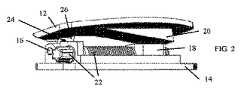
本発明の非限定的な実施形態に従って構築され動作可能である脊椎ケージ10を示す、図1〜図3を参照する。
脊椎ケージ10は、第1の支持板12および第2の支持板14を含み、これらは、最初は互いに平行であってよい(しかし必ずしもそうでなくてもよい)。第1の支持板12は、ヒンジ16によって第2の支持板14に枢動可能に接続される。板移動機18が、第1の支持板12と第2の支持板14との間に位置する。板移動機18は、傾斜表面、または平坦であるかもしくは湾曲していてよい(任意の幾何学的形状)他の適切な押圧構造体を備えた楔であってよい。板移動機18は、第1の支持板12(例えばその下側)における(任意の幾何学的形状を有する)傾斜表面20に接してスライドするように構成される。以下で説明するように、板移動機18が傾斜表面20に接してスライドする動作により、第1の支持板12は、第2の支持板14に対して持ち上げられ、かつ/または傾斜される。See FIGS. 1-3, showing a
The
傾斜表面20(ならびに板移動機18)は、その長さまたは幅に沿った種々の部分に(深さ、角度、長さ、形状、サイズ等の点で)種々の斜面を有し得る。
板移動機18は、リニアアクチュエータ(例えば、第2の支持板14から突出する突起の中を通り抜ける制御ねじ)などのアクチュエータ22によって作動され得る。アクチュエータ22は、(例えば、制御ねじの頭部と噛み合う適切なねじ回しを回すことによって)手で操作されるか、または、自動で操作され得る(例えば、アクチュエータ22は、制御ループにおけるセンサーからのフィードバックなどにより、制御ねじを回す、局所的もしくは遠隔的に操作されるモーターであってよい)。The inclined surface 20 (as well as the plate mover 18) may have various slopes (in terms of depth, angle, length, shape, size, etc.) at various portions along its length or width.
The
ヒンジ16は、第1の支持板12から突出するヒンジハウジング26に形成された細長い穴24(例えば、卵形または楕円形の穴)内に軸支される。ヒンジ16は、細長い穴24内で自由に並進運動および回転することができる。 The
本発明の非限定的な実施形態によると、1つまたは複数の支持部材28が、ヒンジ16および/または第1の支持板12に向かって付勢され得る。支持部材28は、可撓性材料で作られてよく、または、付勢装置30(例えば、板ばねもしくはコイルばね)によって押され得る。最初は、脊椎ケージ10がその収縮構成にあるとき、支持部材28は、単にヒンジ16および/または第1の支持板12に当接する。第1の支持板12が第2の支持板14に対して持ち上げられ、かつ/または傾斜された後、隙間がヒンジ16と第2の支持板14との間および/または第1の支持板12と第2の支持板14との間に形成され、支持部材28は、付勢力によってこの隙間内へと押し込まれる。このように、支持部材28は、第1の支持板12を(持ち上げられ、かつ/または傾斜された)その拡張構成に支持および維持する。1つまたは複数の支持部材28は、(例えば、ピボットを中心として)並進運動および/または回転して移動し得る。 According to a non-limiting embodiment of the present invention, one or
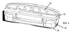
次に、第1の支持板12および/または第2の支持板14から(例えば、直角に)延びる1つまたは複数のキール32を備えた脊椎ケージ10を示す、図4〜図7を参照する。キール32は、脊椎構造内でのケージの適切な取り付け向きを確実にするために使用され得る。図5〜図7は、それぞれ、収縮構成、高さが拡張した構成、および高さが拡張したことに加え傾斜した構成にある、ケージ10を示す。 Next, see FIGS. 4-7 showing a
次に、板12および14が互いに対して傾斜および移動する様式を決定する、第1の支持板12が上を移動するケージ10内の1つまたは複数の内側傾斜路40を示す、図8および図9を参照する。傾斜路40は、傾斜表面20として役立つか、または、別の傾斜表面に加えるものであってよい。例示された実施形態に見られるように、傾斜路のうちの1つの傾斜部分は、傾斜路のうちの別のものとは異なる長さ、高さ、形状または角度を有し得る。ヒンジおよび第1の支持板は、ヒンジが細長い穴内でその最高位置に到達するまで、傾斜路のうちの1つの上で上方にスライドし得る。その後、スライドは、その他の1つまたは複数の傾斜路上で続けられ、第1の支持板の傾斜を引き起こす。よって、傾斜路は、所望の前弯角度を達成するのに役立つ。 Next, FIG. 8 and FIG. 8 show one or more
次に、本発明の非限定的な実施形態に従って構築され動作可能である、脊椎ケージを取り付けるためのアプリケーターツール42および調節ツール44を絵で表す簡略図である図10を参照する。 Next, reference is FIG. 10, which is a pictorial simplification of the
アプリケーターツール42は、近位漏斗43を備えた管であってよい。調節ツール44は、例えばアクチュエータを回すためのねじ回しであってよい。ケージ10は、(雄雌接続、ねじ接続、または任意の他の適切な接続によるなどして)アプリケーターツール42の遠位部分に取り付けられ得る。アプリケーターツール42は、椎間板腔または他の構造への挿入中にケージ10を把持する。調節ツール44は、アプリケーターツール42の管を通って挿入されてアクチュエータに到達することができる。ケージ10がその位置で拡張した後、調節ツール44は取り外される。第1の支持板を持ち上げるか、または傾斜させた後、骨グラフト、コラーゲン、または他の材料が、脊椎ケージ内に、第1の支持板の下などで加えられ得る。 The
Claims (7)
Translated fromJapaneseヒンジ(16)によって第2の支持板(14)に枢動可能に接続され、傾斜表面(20)を有する第1の支持板(12)と、
アクチュエータ(22)によって作動され、前記第1の支持板(12)と前記第2の支持板(14)との間に位置する板移動機(18)であって、前記板移動機(18)は前記傾斜表面(20)に対向する平面を有し、前記板移動機(18)は、前記第1の支持板(12)の前記傾斜表面(20)に面で接しながらスライドするように構成されている、板移動機(18)と、
を含む、脊椎ケージ(10)であって、
前記第1の支持板(12)から突出するヒンジハウジング(26)に形成された細長い穴(24)内に軸支されており、前記細長い穴(24)内で自由に並進運動および回転することができるヒンジ(16)を備え、
前記ヒンジ(16)および/または前記第1の支持板(12)に向かって付勢される1つまたは複数の支持部材(28)をさらに含み、
前記支持部材(28)は、前記第1の支持板(12)を、持ち上げられかつ/または傾斜された構成に支持および維持する、脊椎ケージ(10)。The spinal cage (10)
A first support plate (12) that is pivotally connected to a second support plate (14) by a hinge (16) and has an inclined surface (20).
A plate moving machine (18) that is operated by an actuator (22) and is located between the first support plate (12) and the second support plate (14), and is the plate moving machine (18). Has a plane facing the inclined surface (20), and the plate moving machine (18) is configured to slide while being in contact with the inclined surface (20) of the first support plate (12). The board mover (18) and
Is a spinal cage (10), including
It is axially supported in an elongated hole (24) formed in a hinge housing (26) protruding from the first support plate (12), and freely translates and rotates in the elongated hole (24).Equipped with a hinge (16) that can be used
Further comprising one or more support members (28) urged towards the hinge (16) and / or the first support plate (12).
The support member (28) is a spinal cage (10)that supports and maintains the first support plate (12) in a lifted and / or tilted configuration.
Applications Claiming Priority (1)
| Application Number | Priority Date | Filing Date | Title |
|---|---|---|---|
| PCT/IB2016/051800WO2017168208A1 (en) | 2016-03-30 | 2016-03-30 | Adjustable spinal cage |
Related Child Applications (1)
| Application Number | Title | Priority Date | Filing Date |
|---|---|---|---|
| JP2021000102ADivisionJP7270659B2 (en) | 2021-01-04 | 2021-01-04 | adjustable spine cage |
Publications (2)
| Publication Number | Publication Date |
|---|---|
| JP2019509829A JP2019509829A (en) | 2019-04-11 |
| JP6894918B2true JP6894918B2 (en) | 2021-06-30 |
Family
ID=55963414
Family Applications (1)
| Application Number | Title | Priority Date | Filing Date |
|---|---|---|---|
| JP2018549547AExpired - Fee RelatedJP6894918B2 (en) | 2016-03-30 | 2016-03-30 | Adjustable spinal cage |
Country Status (9)
| Country | Link |
|---|---|
| EP (1) | EP3435923B1 (en) |
| JP (1) | JP6894918B2 (en) |
| KR (2) | KR102591841B1 (en) |
| CN (1) | CN109152645B (en) |
| BR (1) | BR112018069074B1 (en) |
| CA (1) | CA3018624A1 (en) |
| ES (1) | ES2875599T3 (en) |
| RU (1) | RU2715750C1 (en) |
| WO (1) | WO2017168208A1 (en) |
Families Citing this family (22)
| Publication number | Priority date | Publication date | Assignee | Title |
|---|---|---|---|---|
| EP3755273B1 (en) | 2018-02-22 | 2025-04-30 | Warsaw Orthopedic, Inc. | Expandable spinal implant system |
| US11806250B2 (en) | 2018-02-22 | 2023-11-07 | Warsaw Orthopedic, Inc. | Expandable spinal implant system and method of using same |
| CN111655203A (en)* | 2018-02-22 | 2020-09-11 | 华沙整形外科股份有限公司 | Expandable spinal implant system and method of use |
| US12239544B2 (en) | 2020-11-05 | 2025-03-04 | Warsaw Orthopedic, Inc. | Rhomboid shaped implants |
| US12121453B2 (en) | 2020-11-05 | 2024-10-22 | Warsaw Orthopedic, Inc. | Dual wedge expandable implant with eyelets, system, and method of use |
| US11517363B2 (en) | 2020-11-05 | 2022-12-06 | Warsaw Orthopedic, Inc. | Screw driver and complimentary screws |
| US11638653B2 (en) | 2020-11-05 | 2023-05-02 | Warsaw Orthopedic, Inc. | Surgery instruments with a movable handle |
| US12318308B2 (en) | 2020-11-05 | 2025-06-03 | Warsaw Orthopedic, Inc. | Dual expandable inter-body device |
| US11963881B2 (en) | 2020-11-05 | 2024-04-23 | Warsaw Orthopedic, Inc. | Expandable inter-body device, system, and method |
| US11291554B1 (en) | 2021-05-03 | 2022-04-05 | Medtronic, Inc. | Unibody dual expanding interbody implant |
| US11517443B2 (en) | 2020-11-05 | 2022-12-06 | Warsaw Orthopedic, Inc. | Dual wedge expandable implant, system and method of use |
| US11376134B1 (en) | 2020-11-05 | 2022-07-05 | Warsaw Orthopedic, Inc. | Dual expanding spinal implant, system, and method of use |
| US11395743B1 (en) | 2021-05-04 | 2022-07-26 | Warsaw Orthopedic, Inc. | Externally driven expandable interbody and related methods |
| US12171439B2 (en) | 2020-11-05 | 2024-12-24 | Warsaw Orthopedic, Inc. | Protected drill |
| US11833059B2 (en) | 2020-11-05 | 2023-12-05 | Warsaw Orthopedic, Inc. | Expandable inter-body device, expandable plate system, and associated methods |
| US11285014B1 (en) | 2020-11-05 | 2022-03-29 | Warsaw Orthopedic, Inc. | Expandable inter-body device, system, and method |
| US11612499B2 (en) | 2021-06-24 | 2023-03-28 | Warsaw Orthopedic, Inc. | Expandable interbody implant |
| US12295865B2 (en) | 2021-06-24 | 2025-05-13 | Warsaw Orthopedic, Inc. | Expandable interbody implant and corresponding inserter |
| US12268614B2 (en) | 2021-06-24 | 2025-04-08 | Warsaw Orthopedic, Inc. | Interbody implant with adjusting shims |
| WO2022271280A1 (en) | 2021-06-24 | 2022-12-29 | Warsaw Orthopedic, Inc. | Expandable interbody implant and corresponding surgical tool |
| US11730608B2 (en) | 2021-07-13 | 2023-08-22 | Warsaw Orthopedic, Inc. | Monoblock expandable interbody implant |
| US11850163B2 (en) | 2022-02-01 | 2023-12-26 | Warsaw Orthopedic, Inc. | Interbody implant with adjusting shims |
Family Cites Families (20)
| Publication number | Priority date | Publication date | Assignee | Title |
|---|---|---|---|---|
| CA1283501C (en)* | 1987-02-12 | 1991-04-30 | Thomas P. Hedman | Artificial spinal disc |
| US5782832A (en)* | 1996-10-01 | 1998-07-21 | Surgical Dynamics, Inc. | Spinal fusion implant and method of insertion thereof |
| US6641614B1 (en)* | 1997-05-01 | 2003-11-04 | Spinal Concepts, Inc. | Multi-variable-height fusion device |
| DE19807236C2 (en)* | 1998-02-20 | 2000-06-21 | Biedermann Motech Gmbh | Intervertebral implant |
| US7128760B2 (en)* | 2001-03-27 | 2006-10-31 | Warsaw Orthopedic, Inc. | Radially expanding interbody spinal fusion implants, instrumentation, and methods of insertion |
| FR2831796B1 (en)* | 2001-11-06 | 2003-12-26 | Ldr Medical | BONE ANCHORING DEVICE FOR PROSTHESIS |
| US20040087947A1 (en)* | 2002-08-28 | 2004-05-06 | Roy Lim | Minimally invasive expanding spacer and method |
| CN200970284Y (en)* | 2006-02-28 | 2007-11-07 | 赵定麟 | Marmem cervical vertebra artificial intervertebral disc |
| WO2008070863A2 (en)* | 2006-12-07 | 2008-06-12 | Interventional Spine, Inc. | Intervertebral implant |
| US8057547B2 (en)* | 2007-06-12 | 2011-11-15 | Kinetic Spine Technologies Inc. | Articulating intervertebral disc prosthesis |
| US8795366B2 (en)* | 2010-01-11 | 2014-08-05 | Innova Spinal Technologies, Llc | Expandable intervertebral implant and associated surgical method |
| ES2564289T3 (en)* | 2010-10-26 | 2016-03-21 | Christian Röbling | Intervertebral disc prosthesis |
| RU2465870C1 (en)* | 2011-02-28 | 2012-11-10 | Общество с ограниченной ответственностью "Эндокарбон" | Intervertebral disc prosthesis |
| EP2729092B1 (en)* | 2011-08-16 | 2016-09-21 | Stryker European Holdings I, LLC | Expandable implant |
| US9445919B2 (en)* | 2011-12-19 | 2016-09-20 | Warsaw Orthopedic, Inc. | Expandable interbody implant and methods of use |
| US10154914B2 (en)* | 2012-08-08 | 2018-12-18 | Spectrum Spine Ip Holdings, Llc | Expandable intervertebral cage assemblies |
| EP2742914A1 (en)* | 2012-12-14 | 2014-06-18 | FACET-LINK Inc. | Infinitely height-adjustable vertebral fusion implant |
| JP6343820B2 (en)* | 2013-03-15 | 2018-06-20 | スペクトラム スパイン アイピー ホールディングス, エルエルシー | Expandable interbody fusion device and method |
| US9980825B2 (en)* | 2013-05-13 | 2018-05-29 | Biospine, Llc | Adjustable interbody fusion devices |
| US9427331B2 (en)* | 2014-07-15 | 2016-08-30 | Apifix Ltd. | Spinal cage |
- 2016
- 2016-03-30RURU2018138266Apatent/RU2715750C1/enactive
- 2016-03-30ESES16721937Tpatent/ES2875599T3/enactiveActive
- 2016-03-30WOPCT/IB2016/051800patent/WO2017168208A1/ennot_activeCeased
- 2016-03-30KRKR1020187027986Apatent/KR102591841B1/enactiveActive
- 2016-03-30CNCN201680084171.4Apatent/CN109152645B/ennot_activeExpired - Fee Related
- 2016-03-30EPEP16721937.7Apatent/EP3435923B1/enactiveActive
- 2016-03-30CACA3018624Apatent/CA3018624A1/enactivePending
- 2016-03-30JPJP2018549547Apatent/JP6894918B2/ennot_activeExpired - Fee Related
- 2016-03-30KRKR1020237035402Apatent/KR20230148397A/ennot_activeCeased
- 2016-03-30BRBR112018069074-0Apatent/BR112018069074B1/ennot_activeIP Right Cessation
Also Published As
| Publication number | Publication date |
|---|---|
| WO2017168208A1 (en) | 2017-10-05 |
| KR20230148397A (en) | 2023-10-24 |
| EP3435923A1 (en) | 2019-02-06 |
| RU2715750C1 (en) | 2020-03-03 |
| CN109152645B (en) | 2021-05-07 |
| ES2875599T3 (en) | 2021-11-10 |
| BR112018069074B1 (en) | 2023-04-18 |
| CN109152645A (en) | 2019-01-04 |
| CA3018624A1 (en) | 2017-10-05 |
| EP3435923B1 (en) | 2021-04-28 |
| BR112018069074A2 (en) | 2019-01-29 |
| KR20190022450A (en) | 2019-03-06 |
| JP2019509829A (en) | 2019-04-11 |
| KR102591841B1 (en) | 2023-10-20 |
Similar Documents
| Publication | Publication Date | Title |
|---|---|---|
| JP6894918B2 (en) | Adjustable spinal cage | |
| US9827107B1 (en) | Adjustable spinal cage | |
| JP7451411B2 (en) | Intervertebral cage with integrated expansion and angle adjustment mechanism | |
| JP4757342B2 (en) | Interarticular spacer, vertebral body replacement device | |
| JP6995789B2 (en) | Expandable and angle adjustable intervertebral cage | |
| US9974662B2 (en) | Expandable fusion device and method of installation thereof | |
| US8579979B2 (en) | Expandable intervertebral spacers and methods of use | |
| US20130268077A1 (en) | Artificial disk for transforaminal lumbar interbody fusion (tlif) and insertion assembly thereof | |
| AU2005316990A1 (en) | Height- and angle-adjustable motion disc implant | |
| CA2571488A1 (en) | C-shaped disc prosthesis | |
| JP2021058679A (en) | Adjustable spinal cage | |
| KR101085463B1 (en) | Cage with adjustable contact angle | |
| WO2013067454A1 (en) | Bone screw retaining system with pinned retainer |
Legal Events
| Date | Code | Title | Description |
|---|---|---|---|
| A621 | Written request for application examination | Free format text:JAPANESE INTERMEDIATE CODE: A621 Effective date:20190220 | |
| A131 | Notification of reasons for refusal | Free format text:JAPANESE INTERMEDIATE CODE: A131 Effective date:20191224 | |
| A977 | Report on retrieval | Free format text:JAPANESE INTERMEDIATE CODE: A971007 Effective date:20191226 | |
| A601 | Written request for extension of time | Free format text:JAPANESE INTERMEDIATE CODE: A601 Effective date:20200323 | |
| A521 | Request for written amendment filed | Free format text:JAPANESE INTERMEDIATE CODE: A523 Effective date:20200326 | |
| RD03 | Notification of appointment of power of attorney | Free format text:JAPANESE INTERMEDIATE CODE: A7423 Effective date:20200619 | |
| RD04 | Notification of resignation of power of attorney | Free format text:JAPANESE INTERMEDIATE CODE: A7424 Effective date:20200623 | |
| A02 | Decision of refusal | Free format text:JAPANESE INTERMEDIATE CODE: A02 Effective date:20200903 | |
| A521 | Request for written amendment filed | Free format text:JAPANESE INTERMEDIATE CODE: A523 Effective date:20210104 | |
| C60 | Trial request (containing other claim documents, opposition documents) | Free format text:JAPANESE INTERMEDIATE CODE: C60 Effective date:20210104 | |
| C11 | Written invitation by the commissioner to file amendments | Free format text:JAPANESE INTERMEDIATE CODE: C11 Effective date:20210121 | |
| A521 | Request for written amendment filed | Free format text:JAPANESE INTERMEDIATE CODE: A523 Effective date:20210219 | |
| A911 | Transfer to examiner for re-examination before appeal (zenchi) | Free format text:JAPANESE INTERMEDIATE CODE: A911 Effective date:20210222 | |
| C21 | Notice of transfer of a case for reconsideration by examiners before appeal proceedings | Free format text:JAPANESE INTERMEDIATE CODE: C21 Effective date:20210225 | |
| TRDD | Decision of grant or rejection written | ||
| A01 | Written decision to grant a patent or to grant a registration (utility model) | Free format text:JAPANESE INTERMEDIATE CODE: A01 Effective date:20210506 | |
| A61 | First payment of annual fees (during grant procedure) | Free format text:JAPANESE INTERMEDIATE CODE: A61 Effective date:20210604 | |
| R150 | Certificate of patent or registration of utility model | Ref document number:6894918 Country of ref document:JP Free format text:JAPANESE INTERMEDIATE CODE: R150 | |
| LAPS | Cancellation because of no payment of annual fees |