JP6894836B2 - Optical shape detection for instrument tracking in orthopedics - Google Patents
Optical shape detection for instrument tracking in orthopedicsDownload PDFInfo
- Publication number
- JP6894836B2 JP6894836B2JP2017512916AJP2017512916AJP6894836B2JP 6894836 B2JP6894836 B2JP 6894836B2JP 2017512916 AJP2017512916 AJP 2017512916AJP 2017512916 AJP2017512916 AJP 2017512916AJP 6894836 B2JP6894836 B2JP 6894836B2
- Authority
- JP
- Japan
- Prior art keywords
- shape detection
- optical shape
- medical device
- instrument
- medical
- Prior art date
- Legal status (The legal status is an assumption and is not a legal conclusion. Google has not performed a legal analysis and makes no representation as to the accuracy of the status listed.)
- Active
Links
Images


Classifications
- A—HUMAN NECESSITIES
- A61—MEDICAL OR VETERINARY SCIENCE; HYGIENE
- A61B—DIAGNOSIS; SURGERY; IDENTIFICATION
- A61B34/00—Computer-aided surgery; Manipulators or robots specially adapted for use in surgery
- A61B34/20—Surgical navigation systems; Devices for tracking or guiding surgical instruments, e.g. for frameless stereotaxis
- A—HUMAN NECESSITIES
- A61—MEDICAL OR VETERINARY SCIENCE; HYGIENE
- A61B—DIAGNOSIS; SURGERY; IDENTIFICATION
- A61B17/00—Surgical instruments, devices or methods
- A61B17/14—Surgical saws
- A61B17/15—Guides therefor
- A61B17/154—Guides therefor for preparing bone for knee prosthesis
- A—HUMAN NECESSITIES
- A61—MEDICAL OR VETERINARY SCIENCE; HYGIENE
- A61B—DIAGNOSIS; SURGERY; IDENTIFICATION
- A61B17/00—Surgical instruments, devices or methods
- A61B17/16—Instruments for performing osteoclasis; Drills or chisels for bones; Trepans
- A61B17/17—Guides or aligning means for drills, mills, pins or wires
- A61B17/1739—Guides or aligning means for drills, mills, pins or wires specially adapted for particular parts of the body
- A61B17/1764—Guides or aligning means for drills, mills, pins or wires specially adapted for particular parts of the body for the knee
- G—PHYSICS
- G02—OPTICS
- G02B—OPTICAL ELEMENTS, SYSTEMS OR APPARATUS
- G02B6/00—Light guides; Structural details of arrangements comprising light guides and other optical elements, e.g. couplings
- G02B6/24—Coupling light guides
- G02B6/42—Coupling light guides with opto-electronic elements
- G02B6/4292—Coupling light guides with opto-electronic elements the light guide being disconnectable from the opto-electronic element, e.g. mutually self aligning arrangements
- A—HUMAN NECESSITIES
- A61—MEDICAL OR VETERINARY SCIENCE; HYGIENE
- A61B—DIAGNOSIS; SURGERY; IDENTIFICATION
- A61B34/00—Computer-aided surgery; Manipulators or robots specially adapted for use in surgery
- A61B34/20—Surgical navigation systems; Devices for tracking or guiding surgical instruments, e.g. for frameless stereotaxis
- A61B2034/2046—Tracking techniques
- A61B2034/2055—Optical tracking systems
- A—HUMAN NECESSITIES
- A61—MEDICAL OR VETERINARY SCIENCE; HYGIENE
- A61B—DIAGNOSIS; SURGERY; IDENTIFICATION
- A61B34/00—Computer-aided surgery; Manipulators or robots specially adapted for use in surgery
- A61B34/20—Surgical navigation systems; Devices for tracking or guiding surgical instruments, e.g. for frameless stereotaxis
- A61B2034/2046—Tracking techniques
- A61B2034/2061—Tracking techniques using shape-sensors, e.g. fiber shape sensors with Bragg gratings
Landscapes
- Health & Medical Sciences (AREA)
- Life Sciences & Earth Sciences (AREA)
- Surgery (AREA)
- Engineering & Computer Science (AREA)
- Physics & Mathematics (AREA)
- Veterinary Medicine (AREA)
- Nuclear Medicine, Radiotherapy & Molecular Imaging (AREA)
- Biomedical Technology (AREA)
- Heart & Thoracic Surgery (AREA)
- Medical Informatics (AREA)
- Molecular Biology (AREA)
- Animal Behavior & Ethology (AREA)
- General Health & Medical Sciences (AREA)
- Public Health (AREA)
- Optics & Photonics (AREA)
- General Physics & Mathematics (AREA)
- Oral & Maxillofacial Surgery (AREA)
- Dentistry (AREA)
- Orthopedic Medicine & Surgery (AREA)
- Robotics (AREA)
- Physical Education & Sports Medicine (AREA)
- Transplantation (AREA)
- Surgical Instruments (AREA)
- Apparatus For Radiation Diagnosis (AREA)
Description
Translated fromJapanese本開示は医療器具に関し、更に具体的には、コンピュータ支援処置中に医療器具を追跡するための医療用途における光ファイバの形状検知に関する。 The disclosure relates to medical devices, and more specifically to shape detection of optical fibers in medical applications for tracking medical devices during computer-assisted procedures.
コンピュータ支援手術(CAS:computer assisted surgery)システムは、術前計画及び術中外科的ナビゲーション(surgical navigation)のために用いられる。このコンテキストにおいて、術前計画とは、例えば切断、切開、ターゲティングのような外科的ステップのコンピュータ支援決定のことである。計画は、処置の前又は処置の間に行うことができる。術中計画は多くの場合、いずれかの医療撮像モダリティ(imaging modality)(コンピュータ断層撮影法(CT:computed tomography)、磁気共鳴画像法(MRI:magnetic resonance imaging)、超音波、X線、内視鏡検査等)、又は解剖学的モデル(例えば膝モデル)を用いた患者の2D又は3D画像を使用する。CASのコンテキストにおいて、外科的ナビゲーションとは、外科医が術前計画を正確に実行することを可能とする、器具及び患者の解剖学的組織のライブ追跡のことである。外科的ナビゲーションは追跡技術を用いて実施される。 Computer-assisted surgery (CAS) systems are used for preoperative planning and intraoperative surgical navigation. In this context, preoperative planning is a computer-assisted decision for surgical steps such as amputation, incision, and targeting. Planning can be done before or during the procedure. Intraoperative planning is often one of the medical imaging modalities (computed tomography (CT), magnetic resonance imaging (MRI), ultrasound, X-rays, endoscopy. Use 2D or 3D images of the patient using an anatomical model (eg, a knee model) or an examination, etc.). In the context of CAS, surgical navigation is the live tracking of instruments and patient anatomy that allows the surgeon to perform preoperative planning accurately. Surgical navigation is performed using tracking techniques.
追跡技術の一例は、視線光学追跡(line−of−sight optical tracking)である。視線光学追跡技術は、可視範囲又は赤外線範囲のどちらかで動作する光学カメラを使用する。このカメラは、その視野内でマーカを検出し、それらの相対位置に基づいてマーカ配置の位置及び向きを推測するように構成されている。一般に、既知の構成に配置された2台以上のカメラを用いて、立体視及び奥行きの知覚を可能とする。この追跡技術は、カメラ(複数のカメラ)とマーカとの間に途切れない視線を必要とする。 An example of a tracking technique is line-of-sight optical tracking. The line-of-sight optical tracking technique uses an optical camera that operates in either the visible or infrared range. The camera is configured to detect markers within its field of view and infer the position and orientation of the marker placement based on their relative positions. Generally, two or more cameras arranged in a known configuration are used to enable stereoscopic vision and perception of depth. This tracking technique requires an uninterrupted line of sight between the cameras (s) and the markers.
人工膝関節置換術(total knee replacemenet)は、大腿骨及び脛骨の部分を除去し、埋め込み型の人工部品で置換する必要がある。人工膝関節置換術でCASを使用して、術前計画モジュールを用いて適切な切断面を計画すると共に、処置中に骨と器具とを追跡することで計画の実行を可能とする。骨は、多くの場合、埋め込まれる人工部品を受容して整合させるため正しい位置及び角度となるように切断面をガイドする切断ブロックを用いて切除される。CASは、関節を最適な生体力学に戻すため、切断ブロック及びその後のインプラントの位置及び向きの双方の改善を目指している。 Total knee arthroplasty requires removal of the femur and tibia and replacement with an implantable prosthesis. Using CAS in total knee arthroplasty, a preoperative planning module is used to plan the appropriate amputation surface and to track the bone and instrument during the procedure to enable execution of the plan. Bone is often excised using a cutting block that guides the cut surface to the correct position and angle to receive and align the implanted prosthesis. CAS aims to improve both the position and orientation of the amputation block and subsequent implants in order to restore the joint to optimal biomechanics.
人工膝関節置換術のための視線光学追跡CASシステムは、患者に取り付けられて解剖学的追跡を行う視線光学追跡取り付け具セットを含む。視線光学追跡取り付け具は、1つ以上のねじによって骨に強固に取り付けられ、骨からある距離だけ延出する。人工膝関節置換術では、これらの追跡機器が大腿骨及び脛骨の双方に取り付けられてライブの解剖学的追跡を行う。 The line-of-sight optical tracking CAS system for total knee arthroplasty includes a set of line-of-sight optical tracking attachments that are attached to the patient to perform anatomical tracking. The line-of-sight optical tracking attachment is firmly attached to the bone by one or more screws and extends a certain distance from the bone. In total knee arthroplasty, these tracking devices are attached to both the femur and tibia for live anatomical tracking.
既存の光学CASシステムには多くの欠点がある。視線光学CASシステムは、検出カメラと追跡取り付け具との間に遮られない経路を必要とする。カメラから見ることができない追跡取り付け具があると、有効な測定値を与えることができない。処置のあらゆる部分で遮られない経路を維持することは難しい場合があり、例えば動的な生体力学を試験するため骨を操作する場合は特に難しい。これらのCASシステムは、視線を必要とするだけでなく、規定のボリューム内でしか高精度ではない。このボリュームはカメラ位置を基準とし、処置全体を通して維持することは難しい場合があり、関節の操作中は特に難しい。要求される精度を達成するため、視線CASシステムは典型的に、最大寸法で20cmまでの長さを有し得る光学追跡取り付け具内に配置された反射性ボールを使用する。そのような大型取り付け具は、臨床医が利用できる物理的な作業空間を制限し、術中に衝突の危険がある。光学追跡取り付け具のサイズ及び重量のため、強固かつ高精度に骨に取り付けるには大きいねじピンが必要である。場合によっては、単一の追跡取り付け具に2つのねじピンが必要とされる。これらのねじピンは、応力による破損(特に2つのピンを近接して用いる場合)、感染、神経損傷、ピンのゆるみ(ピンの追加又は測定値の不正確さを招く)等の悪影響を引き起こす恐れがある。 Existing optical CAS systems have many drawbacks. The line-of-sight optical CAS system requires an unobstructed path between the detection camera and the tracking fixture. Tracking fixtures that cannot be seen from the camera cannot give valid measurements. Maintaining an unobstructed pathway in every part of the procedure can be difficult, especially when manipulating bone to test dynamic biomechanics. Not only do these CAS systems require a line of sight, but they are only highly accurate within the specified volume. This volume is relative to the camera position and can be difficult to maintain throughout the procedure, especially during joint manipulation. To achieve the required accuracy, line-of-sight CAS systems typically use reflective balls placed within an optical tracking fixture that can have a maximum length of up to 20 cm. Such large fittings limit the physical work space available to the clinician and pose a risk of intraoperative collision. Due to the size and weight of the optical tracking attachment, large screw pins are required for strong and accurate bone attachment. In some cases, a single tracking attachment requires two screw pins. These threaded pins can cause adverse effects such as stress damage (especially when two pins are used in close proximity), infection, nerve damage, and pin loosening (causing additional pins or inaccuracies in measurements). There is.
また、電磁(EM:electromagnetic)ナビゲーションシステムにも多くの欠点がある。視線追跡と同様、EMシステムの要件を満たしながら最適な臨床ワークフローを維持することは難しい場合がある。EMシステムは、磁界発生器の位置に関連して規定されたボリューム内でしか高精度の測定値を与えない。更に、EM磁界内の金属が干渉を生成し、測定精度を低下させる可能性がある。 In addition, electromagnetic (EM) navigation systems also have many drawbacks. As with gaze tracking, it can be difficult to maintain an optimal clinical workflow while meeting the requirements of the EM system. The EM system provides accurate measurements only within the volume specified in relation to the position of the magnetic field generator. In addition, the metal in the EM magnetic field can create interference and reduce measurement accuracy.
本原理に従って、光形状検知システムは、光形状検知ファイバを器具に固定するように構成された取り付け機構を含む。光形状検知ファイバは、器具に接続され、器具の位置及び向きを識別するように構成されている。光形状検知モジュールは、光形状検知ファイバからフィードバックを受信し、動作環境に関連して器具の位置を位置合わせ(レジストレーション)するように構成されている。位置応答モジュールは、器具の位置又は向きに基づいてオペレータにフィードバックを与えて器具の使用をガイドするように構成されている。 According to this principle, the optical shape detection system includes a mounting mechanism configured to secure the optical shape detection fiber to an instrument. The optical shape detection fiber is connected to the fixture and is configured to identify the position and orientation of the fixture. The optical shape detection module is configured to receive feedback from the optical shape detection fiber and to align (register) the device in relation to the operating environment. The position response module is configured to provide feedback to the operator based on the position or orientation of the device to guide the use of the device.
別の光形状検知システムは、1つ以上の光形状検知ファイバからフィードバックを受信するように構成された光形状検知モジュールを含む。1つ以上の器具に少なくとも1つの光形状検知ファイバが接続され、光形状検知ファイバは動作環境に関連して器具を位置的に追跡するために使用される。位置応答モジュールは、器具の位置又は向きに基づいてオペレータにフィードバックを与えて、外科計画に基づいて器具の使用をガイドするように構成されている。動作環境の領域の解剖学的マップが含まれる。1つ以上の器具の位置は解剖学的マップに関連して追跡される。 Another optical shape detection system includes an optical shape detection module configured to receive feedback from one or more optical shape detection fibers. At least one optical shape detection fiber is connected to one or more instruments, and the optical shape detection fiber is used to track the device in position in relation to the operating environment. The position response module is configured to give feedback to the operator based on the position or orientation of the instrument and guide the use of the instrument based on the surgical plan. Includes an anatomical map of the area of the operating environment. The location of one or more instruments is tracked in relation to the anatomical map.
光形状検知を用いて器具を追跡するための方法は、光形状検知ファイバを器具に固定するステップであって、光形状検知ファイバが器具に接続されると共に器具の位置を識別するように構成されているステップと、動作環境の記憶された画像に関連して器具の位置を位置合わせするステップと、光形状検知ファイバからフィードバックを受信して現在の位置を決定するステップと、器具の位置又は向きに基づいて器具の使用をガイドするステップとを含む。 A method for tracking an instrument using optical shape detection is a step of fixing the optical shape detection fiber to the instrument, which is configured to connect the optical shape detection fiber to the instrument and identify the position of the instrument. The step of aligning the position of the device in relation to the stored image of the operating environment, the step of receiving feedback from the optical shape detection fiber to determine the current position, and the position or orientation of the device. Includes steps to guide the use of the device based on.
本開示のこれら及び他の目的、特徴、及び利点は、以下に示すその例示的な実施形態の詳細な説明を添付図面と関連付けて読むことによって明らかとなろう。 These and other objectives, features, and advantages of the present disclosure will become apparent by reading the detailed description of the exemplary embodiments set forth below in association with the accompanying drawings.
本開示は、以下の図面を参照して、以下に示す好適な実施形態の説明を詳細に提示する。 The present disclosure presents in detail a description of the preferred embodiments set forth below with reference to the following drawings.
本原理に従って、外科的処置中に解剖学的マップ又は他の画像上に器具、固定具、機械部品等の相対位置を表示するため使用可能である光形状検知のためのシステム及び方法が提供される。一実施形態では、ツール、器具、固定具等の内部に又は上に、光形状検知ファイバを取り付けるか又は搭載することができる。光形状検知測定を解剖学的マップに位置合わせすることができる。解剖学的マップに対する光形状検知マーカの位置をユーザに表示することができる。光形状検知ファイバを整形外科用器具又はドリル及び切断用具(cutting rig)等の器具に取り付けて、それらの位置を追跡すればよい。更に、光形状検知は、整形外科的処置における軟組織及び/又は骨の追跡に使用してもよい。光形状検知システムは、骨、靭帯、皮膚、挿入物等、又はそれらの組み合わせに取り付けられ得る。 According to this principle, systems and methods for optical shape detection that can be used to display relative positions of instruments, fixtures, mechanical parts, etc. on anatomical maps or other images during a surgical procedure are provided. To. In one embodiment, the optical shape detection fiber can be attached or mounted inside or on a tool, instrument, fixture, or the like. Optical shape detection measurements can be aligned to the anatomical map. The position of the light shape detection marker with respect to the anatomical map can be displayed to the user. Optical shape detection fibers may be attached to orthopedic instruments or instruments such as drills and cutting rigs to track their position. In addition, optical shape detection may be used to track soft tissues and / or bone in orthopedic procedures. The optical shape detection system can be attached to bone, ligaments, skin, inserts, etc., or a combination thereof.
本原理に従って、整形外科的処置又は他の処置において器具を追跡するために光形状検知が用いられる。光形状検知ファイバ(複数のファイバ)は、器具内に永続的に埋め込むか、又は器具に一時的に取り付けることができる。光形状検知ファイバ(複数のファイバ)を備えた器具(OSSセンサ)と患者座標系との間の位置合わせ方法も記載される。正しい位置にある場合オペレータに通知できるか、又は安全もしくは他の目的のため制限を与えることができるインテリジェントなツールに焦点を当てて、光形状検知対応ツールの使用も記載される。 According to this principle, optical shape detection is used to track an instrument in an orthopedic procedure or other procedure. The optical shape detection fiber (s) can be permanently embedded in the fixture or temporarily attached to the fixture. A method of alignment between an instrument (OSS sensor) equipped with optical shape detection fibers (plural fibers) and a patient coordinate system is also described. The use of light shape detection enabled tools is also described, focusing on intelligent tools that can notify the operator if in the correct position or limit for safety or other purposes.
光形状検知(OSS)は、マルチコア光ファイバに沿った光を使用して、そのファイバに沿って形状を復元する。関連する原理は、特徴的なレイリー後方散乱又は制御された格子パターンを用いた光ファイバにおける分布ひずみ測定を利用する。光ファイバに沿った形状は、始点(launch)又はz=0として知られるセンサに沿った特定ポイントで開始し、以降の形状位置及び向きはそのポイントを基準とする。光ファイバは、例えば直径が200ミクロンであり、ミリメートルレベルの精度を維持しながら、長さを最大で数メートルとすることができる。光形状検知ファイバは、広範囲の医療用デバイスに統合されて、ライブ誘導医療処置を行うことができる。一例として、術前画像に光形状検知測定値を重ねた状態で、ガイドワイヤ又はカテーテルを動脈へのナビゲーションのため使用することができる。 Optical shape detection (OSS) uses light along a multi-core optical fiber to restore shape along that fiber. A related principle utilizes distribution strain measurements in fiber optics with characteristic Rayleigh backscatter or controlled lattice patterns. The shape along the optical fiber starts at a specific point along the launch or sensor known as z = 0, and subsequent shape positions and orientations are relative to that point. Optical fibers are, for example, 200 microns in diameter and can be up to several meters in length while maintaining millimeter-level accuracy. Optical shape detection fibers can be integrated into a wide range of medical devices to perform live guided medical procedures. As an example, a guide wire or catheter can be used for navigation to the artery with the optical shape detection measurements superimposed on the preoperative image.
本原理に従って、占有面積が小さく軽量で、形状検知される器具を追跡すると共にこれに一体化することができるOSSファイバセンサが使用される。術中に器具を追跡することにより、インプラント配置の精度を改善し、最終的に臨床成果を改善する機会が与えられる。更に、操作中に患者の解剖学的組織に対する器具の(特に切断器具の)位置認識を保証することで、安全性を向上させることができる。 According to this principle, an OSS fiber sensor is used that occupies a small area, is lightweight, and can track and integrate shape-detected instruments. Intraoperative tracking of the instrument provides the opportunity to improve the accuracy of implant placement and ultimately improve clinical outcomes. In addition, safety can be improved by ensuring the position recognition of the instrument (especially the cutting instrument) with respect to the patient's anatomy during the operation.
本発明が医療器具に関して記載されていることは理解されよう。しかしながら、本発明の教示ははるかに広範であり、いかなる光ファイバ器具にも適用できる。いくつかの実施形態において、本原理は、複雑な生物系又は機械系の追跡又は解析に使用される。具体的には、本原理は、生物系の内部追跡手順や、肺、胃腸管、排出器官、血管のような身体のあらゆる領域における手順に適用可能である。図に示す要素は、ハードウェア及びソフトウェアの様々な組み合わせで実施することができ、単一の要素又は多数の要素に組み合わせられる機能を提供することができる。 It will be appreciated that the present invention is described with respect to medical devices. However, the teachings of the present invention are much broader and can be applied to any fiber optic appliance. In some embodiments, this principle is used for tracking or analysis of complex biological or mechanical systems. Specifically, this principle is applicable to internal tracking procedures of biological systems and procedures in all areas of the body such as lungs, gastrointestinal tract, excretory organs, and blood vessels. The elements shown in the figure can be implemented in various combinations of hardware and software, and can provide functions that can be combined into a single element or multiple elements.
図に示す様々な要素の機能は、専用ハードウェア、及び適切なソフトウェアに関連付けてソフトウェアを実行可能なハードウェアの使用によって提供することができる。プロセッサにより提供される場合、これらの機能は、単一の専用プロセッサ、単一の共有プロセッサ、又はいくつかが共有され得る複数の個別のプロセッサによって提供することができる。更に、「プロセッサ」又は「コントローラ」という言葉の明示的な使用は、ソフトウェアを実行可能なハードウェアを排他的に示すものと解釈されず、限定ではないがデジタル信号プロセッサ(「DSP」)ハードウェア、ソフトウェアを記憶するための読み出し専用メモリ(「ROM」)、ランダムアクセスメモリ(「RAM」)、不揮発性記憶装置等を暗黙的に含むことができる。 The functionality of the various elements shown in the figure can be provided by the use of dedicated hardware and hardware that can run the software in association with the appropriate software. When provided by a processor, these features can be provided by a single dedicated processor, a single shared processor, or a plurality of individual processors, some of which can be shared. Moreover, the explicit use of the term "processor" or "controller" is not construed as an exclusive indication of the hardware in which the software can run, and is not limited to digital signal processor ("DSP") hardware. , Read-only memory (“ROM”) for storing hardware, random access memory (“RAM”), non-volatile storage device, etc. can be implicitly included.
更に、本発明の原理、態様、及び実施形態を説明する本明細書における全ての記述、並びにその具体的な例は、その構造的均等物及び機能的均等物の双方を包含することが意図される。更に、そのような均等物には、現在既知の均等物と将来開発される均等物(すなわち、構造に関係なく同一の機能を実行する開発された任意の要素)との双方を含むことが意図される。このため、例えば本明細書に提示されるブロック図が本発明の原理を具現化する例示的なシステムコンポーネント及び/又は回路の概念図を表すことは、当業者に認められよう。同様に、任意のフローチャート、フロー図等が表す様々なプロセスは、コンピュータ読み取り可能記憶媒体で実質的に表現され、コンピュータ又はプロセッサが明示的に示されていても示されていなくても、そのようなコンピュータ又はプロセッサによって実行され得ることは認められよう。 Furthermore, all descriptions herein, and specific examples thereof, illustrating the principles, embodiments, and embodiments of the present invention are intended to include both structural and functional equivalents thereof. To. Furthermore, such equivalents are intended to include both currently known equivalents and future developed equivalents (ie, any developed elements that perform the same function regardless of structure). Will be done. Thus, it will be appreciated by those skilled in the art that, for example, the block diagrams presented herein represent conceptual diagrams of exemplary system components and / or circuits that embody the principles of the present invention. Similarly, the various processes represented by any flowchart, flow diagram, etc. are substantially represented in a computer-readable storage medium, whether the computer or processor is explicitly or not. It will be acknowledged that it can be run by any computer or processor.
更に、本発明の実施形態は、コンピュータ又は任意の命令実行システムによって又はこれと接続して用いられるプログラムコードを与えるコンピュータ使用可能媒体又はコンピュータ読み取り可能記憶媒体からアクセス可能なコンピュータプログラム製品の形態を取ることができる。この説明の目的のため、コンピュータ使用可能媒体又はコンピュータ読み取り可能記憶媒体は、命令実行システム、命令実行装置、又は命令実行デバイスによって又はこれと接続して用いられるプログラムを含有、記憶、伝達、伝搬、又は転送し得る任意の装置とすることができる。媒体は、電子、磁気、光学、電磁気、赤外線、又は半導体システム(又は装置又はデバイス)又は伝搬媒体とすればよい。コンピュータ読み取り可能媒体の例は、半導体又は固体メモリ、磁気テープ、着脱可能コンピュータディスケット、ランダムアクセスメモリ(RAM)、読み出し専用メモリ(ROM)、剛性磁気ディスク、及び光ディスクを含む。光ディスクの現在の例は、コンパクトディスク−読み出し専用メモリ(CD−ROM)、コンパクトディスク−読み出し/書き込み(CD−R/W)、ブルーレイ(商標)、及びDVDを含む。 Further, embodiments of the present invention take the form of computer program products accessible from computer-enabled or computer-readable storage media that provide program code used by or in connection with a computer or any instruction execution system. be able to. For the purposes of this description, a computer-enabled or computer-readable storage medium contains, stores, transmits, propagates, and contains programs used by or in connection with an instruction execution system, instruction execution device, or instruction execution device. Or it can be any device that can be transferred. The medium may be electronic, magnetic, optical, electromagnetic, infrared, or a semiconductor system (or device or device) or propagation medium. Examples of computer-readable media include semiconductor or solid-state memory, magnetic tape, removable computer diskettes, random access memory (RAM), read-only memory (ROM), rigid magnetic disks, and optical disks. Current examples of optical discs include compact disc-read-only memory (CD-ROM), compact disc-read / write (CD-R / W), Blu-ray ™, and DVD.
ここで、同様の番号が同一又は同様の要素を表す図面を参照し、最初に図1を見ると、一実施形態に従った、整形外科用途及び形状検知対応デバイスを用いる他の用途における光形状検知誘導のためのシステム100が例示的に示されている。システム100はワークステーション又はコンソール112を含むことができ、ここから処置が監督及び/又は管理される。ワークステーション112は好ましくは、1つ以上のプロセッサ114と、プログラム及びアプリケーションを記憶するためのメモリ116と、を含む。メモリ116は、形状検知デバイス又はシステム104からの光フィードバック信号を解釈するように構成された光検知モジュール115を記憶することができる。光検知及び解釈モジュール115は、光信号フィードバック(及び他の任意のフィードバック、例えば電磁(EM)追跡)を用いて、骨又は関節の位置や、他の解剖学的特徴部(feature)、例えば皮膚、靭帯、腱、筋肉、その他の物質又は組織の位置に関連した変形、ゆがみ、その他の変化を復元するように構成されている。 Here, referring to a drawing in which similar numbers represent the same or similar elements, first looking at FIG. 1, the optical shape in an orthopedic application and another application using a shape detection compatible device according to one embodiment. A
形状検知システム104は、1つ以上の光ファイバセンサ102を含む。各センサ102は、1つ又は複数の設定パターンに構成された光ファイバ126を含む。光ファイバ126は、始点マウント125及びケーブル配線127を介してワークステーション112に接続する。ケーブル配線127は必要に応じて、光ファイバ、電気的接続、他の器具類等を含んでもよい。ケーブル配線127は、1つ又は複数の光源106を含むか又はこれと連携することができる光学的問合せユニット108とインタフェースを取る。光学的問合せユニット108は、形状検知システム104からの光信号を送信及び受信する。手術室レール124は、1つ以上の光センサ102のための基準ポイント又は始点(z=0)を含む始点マウント125を含む。 The
光ファイバを用いる形状検知システム104は、光ファイバブラッグ格子センサに基づくものとすればよい。光ファイバブラッグ格子(FBG)は、特定の光波長を反射すると共に他の全てを透過する光ファイバの短いセグメントである。これは、ファイバコアの屈折率に周期的変動を加えて、波長に特定的な誘電体ミラーを生成することにより達成される。従ってファイバブラッグ格子は、ある特定の波長を阻止するインライン光フィルタとして、又は波長に特定的なリフレクタとして使用できる。 The
従来の光ファイバにおける固有の後方散乱を、光形状検知(OSS)のために利用できる。1つのそのような手法は、標準的なシングルモード通信ファイバにおけるレイリー散乱(又は他の散乱)を用いる。レイリー散乱は、ファイバコア内の屈折率のランダムな揺らぎの結果として発生する。これらのランダムな揺らぎは、格子長に沿って振幅及び位相のランダムな変動が存在するブラッグ格子としてモデル化することができる。1本のマルチコアファイバ内に延出する3つ以上のコアでこの効果を用いることにより、対象表面の3D形状及びダイナミクスを追うことができる。 The inherent backscattering of conventional optical fibers can be utilized for optical shape detection (OSS). One such technique uses Rayleigh scattering (or other scattering) in standard single-mode communication fibers. Rayleigh scattering occurs as a result of random fluctuations in the index of refraction within the fiber core. These random fluctuations can be modeled as Bragg grids with random amplitude and phase fluctuations along the grid length. By using this effect with three or more cores extending into one multi-core fiber, the 3D shape and dynamics of the target surface can be tracked.
また、屈折率が変化する各界面においてフレネル反射を使用するファイバブラッグ格子(FBG)も、OSSのために利用できる。いくつかの波長では、様々な周期の反射光は同相であるので、反射には建設的な干渉が存在し、結果として透過には相殺的な干渉が存在する。ブラッグ波長は、温度だけでなくひずみに対して感度が高い。これは、光ファイバセンサの検知要素としてブラッグ格子を使用できることを意味する。FBGセンサでは、測定量(例えばひずみ)はブラッグ波長のシフトを引き起こす。 Also available for OSS are Fiber Bragg gratings (FBGs) that use Fresnel reflections at each interface where the index of refraction changes. At some wavelengths, the reflected light of different periods is in phase, so there is constructive interference in the reflection and, as a result, canceling interference in the transmission. Bragg wavelengths are sensitive to strain as well as temperature. This means that the Bragg grid can be used as a detection element for fiber optic sensors. For FBG sensors, the measured quantity (eg, strain) causes a shift in Bragg wavelength.
OSSの1つの利点は、ファイバの長さにわたって様々なセンサ要素を分散できることである。構造内に埋め込まれたファイバの長さに沿った様々なセンサ(ゲージ)を3つ以上のコアと組み合わせることで、そのような構造の3次元形態を高精度で精密に決定することが可能となる。ファイバの長さに沿って、様々な位置に多数のFBGセンサを位置付けることができる。各FBGのひずみ測定値から、その位置における構造の曲率を推測できる。多数の測定位置から、全体的な3次元形態が決定される。 One advantage of OSS is the ability to disperse various sensor elements over the length of the fiber. By combining various sensors (gauges) along the length of the fiber embedded in the structure with three or more cores, it is possible to determine the three-dimensional form of such a structure with high accuracy and precision. Become. A large number of FBG sensors can be positioned at various positions along the length of the fiber. From the strain measurement value of each FBG, the curvature of the structure at that position can be estimated. The overall three-dimensional morphology is determined from a number of measurement positions.
一実施形態において、1つ以上の光センサ102は1つ以上の器具128に接続されている。器具128は、多数の異なるカテゴリのデバイス、ツール、固定具、取り付け具等を含み得る。例えば、多数の異なる器具128が整形外科手術中に使用され得る。これらの器具128は2つのカテゴリに大別することができる。例えば、外科医又はオペレータによって手で持たれるものと、患者又は被験者160に対して物理的に取り付けられるものである。例示の目的のため、患者に取り付けられ得るそのような器具128の例には、切断ブロック、ジグ、ねじ、ピン、トライアルインプラント等が挙げられる。外科医又はオペレータによって手で持たれ得るそのような器具128の例には、位置合わせポインタ、骨ドリル、骨のこぎり、オステオーム(osteome)(のみと同様)、外科用メス、鉗子、吸引器等が挙げられる。いくつかの実施形態では、器具128は、プローブ、内視鏡、ロボット、電極、ドリル、切断用具、又はその他の医療用部品等を含み得る。 In one embodiment, one or more
特に有用な実施形態において、OSSファイバセンサ102は、多数の手法で器具(複数の器具)128に取り付けることができる。例えば、ファイバセンサ102の取り付けは永続的であり得る。骨ドリル又は骨のこぎり等の器具では、専用のOSSファイバセンサ102を器具128に永続的に取り付けるか又はその内部に埋め込むことが望ましい場合がある。ファイバセンサ102は、例えば(利用可能な場合は)電気ケーブル、又は他のアクセサリを介して器具128内に入れることができる。ファイバセンサ102は、器具128のハンドル内で又は器具ツールチップ内で終端させることができる。あるいは、ファイバセンサ102の取り付けは一時的であり得る。例えばオステオーム又は切断ブロック等の器具では、ファイバセンサ102を器具128に永続的に取り付けることは望ましくないか又は費用効果が低い場合がある。永続的な取り付けの代替案は、OSSファイバセンサ102を一時的に添付できる器具128上の機構(feature)(複数の機構)である。そのような実施形態は、一方がOSSテザーの遠位端に、他方が器具上にある2つ以上の嵌合取り付けポイント134、136を有する取り付け機構130を有する。 In a particularly useful embodiment, the
器具側では、取り付けポイント136は器具設計の一体部分とすることができるか、又はねじ、締め具、接着剤、又は同様の機構によって後付け又は添付することができる。磁石、留め金、スナップ留め等の一時的な固定方法を用いて、ファイバセンサ102上の取り付けポイント134を器具128上の取り付けポイント134に対して取り付け及び取り外しすることができる。取り付け機構130は好ましくは、器具128の正しい向きが確実にわかるように特定方向でのみ(すなわち一方向でのみ)取り付けるため、取り付けポイント134と136との間のインタフェースを含む。 On the instrument side, the
ワークステーション112は、形状検知システム104からフィードバックを受信し、1つ以上の光センサ102がボリューム131内のどこに存在したかに関する位置(及び向き)データを記録するように構成された画像発生モジュール148を含む。空間又はボリューム131内の、1つ以上の光センサ102の画像135、又はファイバが取り付けられた器具128の仮想表現を、ディスプレイデバイス118に表示することができる。ワークステーション112は、被験者(患者)又はボリューム131の内部画像を見るためのディスプレイ118を含み、撮像デバイス110が収集した画像上でのオーバーレイとして又は検知デバイス104の他のレンダリングとしての画像135を含み得る。撮像デバイス110は、任意の撮像システムを含み得る(例えば、コンピュータ断層撮影法(CT)、超音波、フルオロスコープ、磁気共鳴画像法(MRI)等)。また、ディスプレイ118によってユーザは、ワークステーション112並びにその構成要素及び機能、又はシステム100内の他のいかなる要素ともインタラクトすることができる。これはインタフェース120によって更に容易になる。インタフェース120は、キーボード、マウス、ジョイスティック、触覚デバイス、又は他の任意の周辺装置又は制御装置を含み、ワークステーション112からのユーザフィードバック及びワークステーション112とのインタラクションを可能とする。 The
システム100は、光形状検知に基づき、外科的手順の間や他の場合に解剖学的マップ137(例えばボリューム131の解剖学的画像)上に重ねて器具128の位置を表示するために使用できる。システム100は、患者160の解剖学的位置(例えば皮膚、筋肉、靭帯、骨等)と対照され得る器具128に光形状検知ファイバ102を一体化することを含む。光形状検知センサ102を解剖学的マップ137に位置合わせし、光形状検知センサ102、従ってこれに接続された器具128の位置(複数の位置)を表示することで、ユーザに対して許容限度及び警告を示し、潜在的な損傷や、計画もしくは他の基準で示される対象範囲外での動作について警報を与えることができる。 The
光センサ102は、1つ以上の基準位置、グローバル座標系、又は他の任意の座標系に位置合わせされたそれら自体の座標系を有し得る。光形状検知ファイバ102は、形状ごとの位置合わせ(shape−to−shape registration)、始点位置の機械的位置合わせ、ポイントベースの位置合わせ等を含む多数の技法を用いて、相互に位置合わせすることができる。形状検知測定値を臨床医にとって有用なものにするため、解剖学的マップ137に関連付けて測定値を提供することができる。解剖学的マップは、術前画像(例えばCT、MRI、フルオロスコープ、もしくは超音波画像)、又は術中画像(例えばライブ)とすることができる。場合によっては、位置合わせステップ中に解剖学的モデルをモーフィングして特徴部の測定値にマッチングさせる。本明細書において、術前に又は任意のソースから取得された3D表面又はボリュームをモデルと呼ぶ。 The
いったん光形状検知ファイバ102が解剖学的マップ又は他の基準(例えば骨138)に配置されて位置合わせされたら、ファイバ位置をオペレータに関連して(例えばディスプレイ118上に)表示することができる。解剖学的マップ上のOSSデータの表示は多くの形態を取り、複数の機能を与え得る。 Once the optical
システム100は、例えば切断及びドリルガイドや、必要な切断部及び孔を生成する器具のような器具128を、より高精度に配置することを可能とする。しかしながら、器具128の位置及び向きがわかれば、更に「インテリジェントな」機能性を追加することも可能となる。一例では、位置応答モジュール144によって切断面の自動制御が与えられる。骨ドリル又は骨のこぎり等の形状検知切断器具を用いる場合、患者の解剖学的組織に対する切断面の既知の位置に基づいて、ドリルビット又はのこぎりの刃を能動的に停止させることができる。器具の速度又は他の機能をその位置に従って変更してもよい。一実施形態において、外科医は、切断器具が自動的にオフに切り換わるか又は器具の動作が変更される仮想的な「安全ゾーン」を示すことができる。 The
位置応答モジュール144は、器具の位置又は向きに基づくフィードバックをオペレータに与えて器具128の使用をガイドするように構成されている。位置応答モジュール144は、動作環境において識別されたゾーンに関連する器具の位置に基づいて器具機能を制御し、器具が特定の向き又はロケーションで位置決めされた場合にフィードバックをオペレータに与え、器具の位置が変化した場合に器具の使用を停止し、又は器具の位置が変化した場合に器具の機能を開始するように構成され得る。ユーザに与えられるフィードバックは、例えば聴覚、視覚、触覚等を含み、器具128のコンソール112上に位置付けられる出力デバイス150を介して与えられるか、又は例えばインタフェース120、ディスプレイ118を介して等の他の方法で与えられ得る。 The
別の例では、器具が正しい向きで位置決めされた場合、モジュール144によって、オペレータフィードバック(例えば聴覚、視覚、触覚等)を(器具128を介して)与えることができる。器具128の位置及び向きを正しく設定することは、正しいインプラント配置の保証又は他のタスクのための重要なパラメータである。この理由から、切断及びドリルガイドが慣例的に用いられている。外科医のための追加入力として、手持ち型の器具128の位置及び向きが所望の位置の閾値内にある場合、システムは聴覚、視覚、触覚又は触知フィードバックを用いて(例えばインタフェース120又は器具128を介して)オペレータに警報を与えることができる。更に別の例では、制御モジュール144を用いて器具と骨との接触を検知してもよい。OSSファイバセンサ102が永続的に器具128内に埋め込まれる実施形態では、器具の骨との接触が検出されるように一体化を設計することができる。そのような実施形態は、最初のポイントベース位置合わせの一部として用いられる(すなわち位置合わせポインタ)位置合わせ器具に特に適している。そのような実施形態は、器具と骨との間の接触力の力検知にも使用され得る。 In another example, the
更に別の例では、制御モジュール144を用いて切断又はドリルガイドの自動位置決めを実行してもよい。患者に関連して位置合わせされ、術前計画に基づいて最適な切断面を自動的に設定できる、メカトロニクス的に(例えば機械的及び電子的に)作動される切断ガイド(128)を用いることができる。これは、切断及びドリルガイドの必要な位置への完全に手動の調整に取って代わるものである。こういった従来の手動調整ステップは、切断ガイドを最初に骨に取り付けた後に行われ、運動範囲は極めて限られている。 In yet another example, the
本原理は、手術ガイド及びナビゲーションのための光形状検知ファイバのいかなる使用にも適用される。特に有用な実施形態において、本原理は、膝置換術、前十字靭帯(ACL:anterior cruciate ligament)修復、股関節置換、脳外科手術、肘手術、及び他のそのような用途において使用され得る。更に、OSSは、例えば(増強及び通常)レイリー散乱、並びに形状検知ファイバのファイバブラッグ実施等、いかなるタイプの反射又は散乱現象も利用し得る。本原理は、手作業及びロボットによるナビゲーションシステムと共に使用できる。 This principle applies to any use of optical shape sensing fibers for surgical guides and navigation. In a particularly useful embodiment, the principle can be used in knee replacement, anterior cruciate ligament (ACL) repair, hip replacement, brain surgery, elbow surgery, and other such applications. In addition, OSS can utilize any type of reflection or scattering phenomenon, such as (enhanced and usually) Rayleigh scattering, as well as fiber Bragging of shape-sensing fibers. This principle can be used with manual and robotic navigation systems.
図2A〜図2Cを参照すると、光形状検知用の光ファイバを取り付け機構130(例えばポイント134及び136から形成される)に取り付けるための構成例が例示的に示されている。光形状検知ファイバ126は、多数の手法で取り付け機構130に取り付けることができる。図2A及び図2Bに示すように、光ファイバ126の取り付け機構130への機械的クランピング(光ファイバコーティングが無傷の場合もそうでない場合もある)は、ファイバが載っている溝又は経路を含み得る。経路は、s字形状210のような所定の形状を含み得る(図2A又はループ212(図2B))。図2Cの例では、ファイバの直線部分214は取り付け機構130の材料216に埋め込まれ、湾曲部分は取り付け機構130の周囲の空間で自由に変形可能である。埋め込みファイバの他の任意の形状も使用可能である(例えばループ212又はs字形状210以外のもの)。 With reference to FIGS. 2A to 2C, a configuration example for attaching the optical fiber for optical shape detection to the attachment mechanism 130 (for example, formed from the
ファイバ126は、光ファイバ126上の接着剤又はクランプを用いて取り付け機構130に接続され得る(光ファイバコーティングが無傷の場合もそうでない場合もある)。あるいは、浮動ファイバ(free−floating fiber)126を、光学的に追跡可能な(形状検知される)既知の形状で通過させてもよい。これら及び/又は他の取り付けモードの組み合わせも想定される。 The
一実施形態において、光ファイバ126は取り付け機構130に永続的に取り付けられる。別の実施形態では、取り付け機構130は分割することができ、取り付け機構130の半分を固定部分に対して永続的に取り付けると共に、他の半分をOSSテザー(ファイバ126)に取り付けるようになっている。 In one embodiment, the
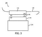
図3を参照すると、2分割取り付け機構130は分割することができ、必要に応じて臨床医が嵌合取り付けポイント134、136を接続及び分離できる。これにより臨床医は、処置中に2つの半分の部分134、136を適切なポイントで取り付けるか又は接合することができる。嵌合取り付けポイント134、136は好ましくは、嵌合機械部分140を用いて、1つの特定の向きでのみ接合される(例えば固定される(keyed))。嵌合取り付けポイント134、136の接続は、例えばクリップ、留め金、ねじ、磁石のような締結具(図示せず)を用いて達成できる。この2分割ボタン式構成によって、処置の間に1つのOSSテザー(ファイバ126)を多数のやり方で使用することが可能となり、例えば、器具128上の様々な嵌合取り付けポイント134にファイバを取り付けることができる。 With reference to FIG. 3, the
図4を参照すると、本原理に従って光ファイバセンサ102は、複数の異なる器具128に対して取り外し及び接続を実行できるように構成され得る。各器具128は、光ファイバセンサ102の嵌合部213を受容するように構成された取り付けポイント202を特徴として備えている。図4は、整形外科的処置において使用される骨ドリル204及び切断ブロック206を例示的に示す。光ファイバセンサ102は、その遠位端に嵌合部213を特徴として備えている。光ファイバセンサ102は、器具(204、206)間で手動により移動させることができる。 With reference to FIG. 4, according to this principle, the
このような一時的な取り付けスキームの1つの利点は、処置の過程において単一のファイバセンサ102を多数の異なる器具間で切り換えることにより、必要なOSSコンソール数を最小限に抑えられることである。追加の実施形態では、長さに沿って多数の取り付けポイント202を用いる単一の光ファイバセンサ102を使用してもよい。そのような実施では、1つのファイバセンサ102によっていくつかの器具を同時に追跡することができる。 One advantage of such a temporary mounting scheme is that the number of OSS consoles required can be minimized by switching a
図5を参照すると、一緒に位置合わせされ得る4つの座標系が例示的に図示されると共に、骨座標系内の器具128を追跡するために実行可能な3つの位置合わせが図示されている。3つの位置合わせは、器具座標系306から器具OSSセンサ座標系302に対する位置合わせ310と、器具OSSセンサ座標系302から骨OSSセンサ座標系304に対する位置合わせ312と、骨OSSセンサ座標系304から骨座標系308に対する位置合わせ314と、を含む。 With reference to FIG. 5, four coordinate systems that can be aligned together are illustrated exemplary, and three alignments that can be performed to track the
器具座標系306は、器具を追跡するOSSセンサ302に位置合わせされる。これは、例えば参照テーブルを用いて事前に(a−priori)実行し検出することができる。器具及び骨を追跡するOSSセンサは、多くの手法で位置合わせすることができる(例えば形状ごとの位置合わせ、ポイントベースの位置合わせ、又はもっとも単純な場合、それらの原点間の既知の機械的変換)。骨座標系308は、例えば膝の身体目標物を用いて骨を追跡するOSSセンサ302に位置合わせされる。いったん3つの位置合わせ310、312、314が行われたら、器具は骨に位置合わせされている。 The instrument coordinate
引き続き図5を参照しながら図6を見ると、器具128と光ファイバセンサ102との位置合わせの例示的なワークフローが示されている。このワークフローは、事前402及び手術室(operating theater)412のような複数の動作領域に分割され得る。ブロック404では、試験用光ファイバセンサを器具に取り付けることができる。ブロック406では、センサが取り付けられた器具を位置合わせ固定具内に配置する。位置合わせ固定具は、センサと器具の位置合わせを試験又は初期化するため既知の位置を含み得る。ブロック408では、位置合わせを検証し、器具座標系(306)とセンサ座標系(302)との間の変換を行うことができる。これによって位置合わせ310が行われる。ブロック410では、検証した位置合わせ変換を、例えば参照テーブル426にセーブする。最初の変換は器具又は取り付けデバイスのタイプに応じて生成することができる。参照テーブル426は、後述するように、器具識別(器具ID)データ及び対応して使用される変換にインデックスを付ける。参照テーブル426又は同様のメモリ構造を用いて、器具(128)とセンサ(102)との間の位置合わせを保持することができる。ファイバ取り付けポイントに対する各器具の正確な変換は、別個に生成され、OSSユーザインタフェース内でアクセス可能である。また、センサ(102)と器具(128)との間のライブ位置合わせのため、位置合わせ固定具を手術室412内に現場配置することも可能である。 Looking at FIG. 6 with reference to FIG. 5, an exemplary workflow of alignment of the
器具OSSセンサ座標系(302)に対する器具座標系(306)の位置合わせ310は、センサ(102)を器具(128)に永続的に取り付ける/一体化することを含み得る。この場合、器具に対する一体化又は取り付けの時に、その器具に関連してセンサを位置合わせする必要がある。これは、センサ(102)と共に器具(128)を位置合わせ固定具内に配置することで実行可能である。この固定具は、例えば器具の金型とすることができ、又は既知の手法で器具を移動させる動的固定具(枢動固定具等)とすることで適切な変換を与えることができる。別の実施形態では、再取り付け可能センサ(102)を器具(128)上に配置する。この場合、ファイバ取り付けは、器具に関連して既知の機械的な位置及び向きとする(例えば器具の特徴部上のクランプ)。研究室では、代表的なセンサ、器具、及び取り付け具を用いて変換を生成することができる。これは、取り付け具の設計によって機械的に知ることも可能である。いずれにせよ、変換が決定されて記憶される。
手術室412では、ブロック414において器具(128)を選択する。所与の器具が作動されるか又は選択されると、手術室スタッフのメンバーがライブラリから適切な器具を選択することができる。あるいは、無線周波数識別(RFID)又は同様のデバイス識別方法を用いて、正しい器具の自動検出を実施することも可能である。ブロック416において、器具(128)に光ファイバセンサ(102)を取り付ける。ブロック418において、ソフトウェアで器具タイプ(器具ID)を選択する。ブロック420において、ソフトウェアは参照テーブル426から対応する変換を検索する。この情報を用いて、位置合わせ312及び314を実行すればよい。 In the operating room 412, the instrument (128) is selected at
骨に対する位置合わせが好ましい場合、骨OSSセンサ座標系304に対する器具OSSセンサ座標系302の位置合わせ312を行えばよい。OSS追跡器具が骨自体のOSS追跡と併用され、全ての要素が1つの座標系に位置合わせされる可能性がある。これは、骨を追跡するファイバ(複数のファイバ)及び器具を追跡するファイバ(複数のファイバ)の始点固定具を既知の幾何学的関係に固定するよう保証することで、容易に達成できる。それらが既知の幾何学的関係にない場合、形状座標系間の位置合わせは、ポイントベース又は形状ごとの位置合わせで達成することができる。単一センサ手法の場合、器具及び骨は自動的に同一の座標系内にある。骨座標系308に対する骨OSSセンサ座標系304の位置合わせ314は、骨目標物のポイントベースの位置合わせによって実行可能である。他の位置合わせ技法を使用してもよい。ブロック422において、任意選択的な検証ステップを実行することができる。これは、器具先端を既知の位置に保持すること及び結果を比較することを含み得る。 When the alignment with respect to the bone is preferable, the
本明細書に記載される実施形態が例示的に膝関節を使用することは理解されよう。しかしながら、いかなる関節又は他の解剖学的特徴部、人口装具、又はモデルも、本原理を使用し得る。更に、本明細書に記載される実施形態を組み合わせて本原理の利点を更に増大させてもよい。例えば、縫合OSSファイバ実施形態を皮膚に取り付けたOSSファイバと組み合わせること、及び/又はスリーブを一体化OSSファイバと組み合わせることができる。 It will be appreciated that the embodiments described herein use the knee joint exemplary. However, any joint or other anatomical feature, artificial brace, or model may use this principle. In addition, the embodiments described herein may be combined to further enhance the advantages of this principle. For example, sutured OSS fiber embodiments can be combined with skin-attached OSS fibers and / or sleeves can be combined with integrated OSS fibers.
図7を参照すると、光形状検知を用いて器具を追跡するための方法が例示的に示されている。ブロック502において、光形状検知ファイバを器具に固定する。光形状検知ファイバは、器具に接続され、器具の位置を識別するように構成されている。光形状検知ファイバを複数の器具に交換可能であるように搭載してもよい。 With reference to FIG. 7, a method for tracking an instrument using optical shape detection is exemplified. At
ブロック504において、動作環境の記憶画像に関連して器具の位置を位置合わせする。動作環境は医療処置のための手術室を含み得る。器具の位置は解剖学的マップに関連して追跡することができる。ブロック506において、光形状検知ファイバからフィードバックを受信して器具の位置(及び向き)を決定する。位置情報を用いて情報フィードバックをユーザに与える。この情報は多くの形態を取ることができる。例えばユーザは、追跡対象の器具が正しく位置決めされているという信号を受信し得る。ユーザは、器具が範囲外に移動したか又は安全ゾーンから出たというフィードバックを受信し得る。ユーザは、器具を特定の領域内に配置することが許可されるか否かのフィードバックを受信し得る。 At
ブロック508では、器具の位置又は器具に加わる力/ひずみに基づいて、使用又は機能について器具機能をガイドすることができる。ここで、使用のガイドとは、器具の使用を拡張もしくは改善する情報、又は器具をより安全に使用する情報を与えることを意味する。例えばブロック510では、動作環境内で識別されたゾーンに対する器具の位置に基づいて器具を制御する。これは、例えば安全ゾーンのような識別されたゾーンから出た場合に器具をオフにすることを含み得る。一例では、適切な深さに到達した場合、ドリルをオフに切り換えるか、又は表示もしくは音によって警告を発する。別の実施形態では、表面が検出されるまで、例えば器具が骨と接触するまで、器具を挿入することができる。器具の位置が変化した場合、又は測定された力もしくはひずみの測定値が閾値を超えた場合、器具の使用を開始又は停止することができる。器具の機能を、位置の変化又は測定された力もしくはひずみに対応させてもよい。 Block 508 can guide instrument function for use or function based on the position of the instrument or the force / strain applied to the instrument. Here, the usage guide means to provide information for expanding or improving the use of the device or for using the device more safely. For example, block 510 controls the instrument based on the position of the device with respect to the zone identified in the operating environment. This may include turning off the equipment when exiting an identified zone, such as a safety zone. In one example, when the appropriate depth is reached, the drill is turned off or a display or sound alert is given. In another embodiment, the instrument can be inserted until the surface is detected, for example until the instrument comes into contact with the bone. The instrument can be started or stopped when the position of the instrument changes, or when the measured force or strain reading exceeds the threshold. The function of the instrument may correspond to a change in position or a measured force or strain.
ブロック512では、器具が特定の向きで位置決めされた場合、位置フィードバック(例えば物理的フィードバック)をオペレータに与えることができる。例えば器具が適切に整合された場合、例えば光、音、振動、メッセージ等のインジケータを与えればよい。これは、所与の座標系で与えられる軸に沿って及び/又は計画に従って切断ガイドの自動位置決めを可能とすることにより切断ガイド等を調整することも含む。 At
添付の特許請求の範囲を解釈する際、以下のことを理解するべきである。
a)「comprising(備える)」という言葉は、所与の請求項に列挙されるもの以外の要素又は行為の存在を除外しない。
b)ある要素の直前の「a(1つの)」又は「an(1つの)」という言葉は、複数のそのような要素の存在を除外しない。
c)特許請求項におけるいかなる参照符号もそれらの範囲を限定しない。
d)いくつかの「means(手段)」は、同一のアイテム又はハードウェア又はソフトウェアにより実施される構造又は機能によって表され得る。
e)特に指示のない限り、行為の特定の順序が要求されることは意図されない。In interpreting the appended claims, the following should be understood:
a) The word "comprising" does not preclude the existence of any element or act other than those listed in a given claim.
b) The word "a" or "an" immediately preceding an element does not exclude the existence of more than one such element.
c) No reference code in the claims limits their scope.
d) Some "means" may be represented by structures or functions performed by the same item or hardware or software.
e) Unless otherwise instructed, it is not intended that a particular order of conduct is required.
整形外科における器具追跡のための光形状検知の好適な実施形態(これらは限定でなく例示を意図している)について記載したが、上記の教示に照らして、当業者によって変更及び変形を行い得ることに留意すべきである。従って、添付の特許請求の範囲で概要が述べられる本明細書に開示された実施形態の範囲内に含まれる変更が、開示された特定の実施形態で行われ得ることは理解されよう。特に特許法により必要とされるように詳細を記載したが、特許請求され、特許証により保護されることが望まれるものは、添付の特許請求の範囲に記載される。 Although preferred embodiments of optical shape detection for instrument tracking in orthopedics (these are intended to be exemplary without limitation) have been described, they may be modified and modified by one of ordinary skill in the art in light of the above teachings. It should be noted that. It will therefore be appreciated that changes contained within the embodiments disclosed herein, outlined in the appended claims, can be made in the particular embodiments disclosed. In particular, the details are described as required by the Patent Law, but those claimed for patent and desired to be protected by a letter certificate are described in the appended claims.
Claims (12)
Translated fromJapanese前記光形状検知ファイバからフィードバックとして光信号を受信し、前記光形状検知ファイバが接続された前記医療器具と、医療処置のための手術室にて取得した解剖学的マップとを位置合わせする光形状検知モジュールと、
前記医療器具の位置又は向きに基づいてオペレータに聴覚、視覚又は触覚のオペレータフィードバックを与えて、前記医療器具の使用をガイドする位置応答モジュールと、
を備え、
前記位置応答モジュールは、前記医療器具が特定の向きで位置決めされた場合に前記オペレータフィードバックをオペレータに与える、光形状検知システム。An attachment mechanism that fixes an optical shape detection fiber thatis connected to a medical device and is configured to identify the position and orientation of themedical device to the medical device.
An optical shape that receives anoptical signal as feedback from the optical shape detection fiber and aligns themedical device to which the optical shape detection fiber is connected with an anatomical map acquired in an operating room for medical treatment. With the detection module
Hearing the operator based on the position or orientation of themedicalinstrument, givingthe operator feedbackof visual or tactile, and position response module to guide the use of themedical instrument,
With
The position response module is an optical shape detection system that provides theoperatorfeedback when the medical device is positioned in a specific orientation.
前記1つ以上の光形状検知ファイバが接続された1つ以上の前記医療器具と、
前記医療器具の位置又は向きに基づいてオペレータに聴覚、視覚又は触覚のオペレータフィードバックを与えて、外科計画に基づいて前記医療器具の使用をガイドする位置応答モジュールと、
医療処置のための手術室にて取得した解剖学的マップであって、前記医療器具が位置合わせされる前記解剖学的マップと、
を備え、
前記位置応答モジュールは、前記医療器具が特定の向きで位置決めされた場合に前記オペレータフィードバックをオペレータに与える、光形状検知システム。An optical shape detection modulethat is connected to a medical device and receives an optical signal as feedback from one or more optical shape detection fibersconfigured to identify the position and orientation of the medical device.
With the one or moremedical devices to which the one or more optical shape detection fibers are connected,
Hearing the operator based on the position or orientation of themedicalinstrument, givingthe operator feedbackof visual or tactile, and position response module to guide the use of themedical instrument on the basis of the surgical plan,
An anatomical map obtained in an operating room for a medical procedure, the anatomical map to which themedical device is aligned, and the anatomical map.
With
The position response module is an optical shape detection system that provides theoperatorfeedback when the medical device is positioned in a specific orientation.
前記光形状検知ファイバを前記医療器具に接続して固定するステップと、
医療処置のための手術室にて取得した解剖学的マップと前記医療器具とを位置合わせするステップと、
前記光形状検知ファイバからフィードバックとして光信号を受信して現在の位置を決定するステップと、
前記医療器具が特定の向きで位置決めされた場合に聴覚、視覚又は触覚のオペレータフィードバックをオペレータに与えるステップと、
を備える、方法。A method for tracking amedical device using an optical shape sensingfiberconfigured to identify the position and orientation of the medical device.
A step of fixingby connectingthe optical shape detection fiber tosaid medical instrument,
Aligning theanatomical map and themedical deviceobtained in the operating room for medical treatment,
A step of receiving anoptical signal as feedback from the optical shape detection fiber to determine the current position,
A step of givingthe operator auditory, visual or tactile operator feedback when the medical device is positioned in a particular orientation.
A method.
Applications Claiming Priority (3)
| Application Number | Priority Date | Filing Date | Title |
|---|---|---|---|
| US201462047326P | 2014-09-08 | 2014-09-08 | |
| US62/047,326 | 2014-09-08 | ||
| PCT/IB2015/056416WO2016038489A2 (en) | 2014-09-08 | 2015-08-25 | Optical shape sensing for instrument tracking in orthopedics |
Publications (3)
| Publication Number | Publication Date |
|---|---|
| JP2017528220A JP2017528220A (en) | 2017-09-28 |
| JP2017528220A5 JP2017528220A5 (en) | 2018-10-04 |
| JP6894836B2true JP6894836B2 (en) | 2021-06-30 |
Family
ID=54252349
Family Applications (1)
| Application Number | Title | Priority Date | Filing Date |
|---|---|---|---|
| JP2017512916AActiveJP6894836B2 (en) | 2014-09-08 | 2015-08-25 | Optical shape detection for instrument tracking in orthopedics |
Country Status (5)
| Country | Link |
|---|---|
| US (1) | US11793578B2 (en) |
| EP (1) | EP3191883A2 (en) |
| JP (1) | JP6894836B2 (en) |
| CN (2) | CN107072719A (en) |
| WO (1) | WO2016038489A2 (en) |
Families Citing this family (12)
| Publication number | Priority date | Publication date | Assignee | Title |
|---|---|---|---|---|
| EP4477143A3 (en)* | 2014-09-05 | 2025-03-19 | PROCEPT BioRobotics Corporation | Physician controlled tissue resection integrated with treatment mapping of target organ images |
| US10639007B2 (en) | 2014-12-02 | 2020-05-05 | Koninklijke Philips N.V. | Automatic tracking and registration of ultrasound probe using optical shape sensing without tip fixation |
| CN108472082B (en)* | 2015-12-29 | 2021-08-10 | 皇家飞利浦有限公司 | Registration system for medical navigation and method of operation thereof |
| CN108472096B (en) | 2015-12-31 | 2021-11-16 | 史赛克公司 | System and method for performing a procedure on a patient at a target site defined by a virtual object |
| CN116211467A (en) | 2016-12-05 | 2023-06-06 | 皇家飞利浦有限公司 | System and method for determining a length of a non-shape sensing interventional device using a shape sensing guidewire and determining a status of the guidewire relative to the interventional device |
| US10292774B2 (en) | 2017-07-28 | 2019-05-21 | Zimmer, Inc. | Bone and tool tracking with optical waveguide modeling system in computer-assisted surgery using patient-attached multicore optical fiber |
| WO2019032450A1 (en)* | 2017-08-08 | 2019-02-14 | Intuitive Surgical Operations, Inc. | Systems and methods for rendering alerts in a display of a teleoperational system |
| US11129679B2 (en) | 2017-11-14 | 2021-09-28 | Mako Surgical Corp. | Fiber optic tracking system |
| EP3713491B1 (en) | 2017-11-22 | 2025-02-26 | Mazor Robotics Ltd. | A system for verifying hard tissue location using implant imaging |
| US11576729B2 (en)* | 2019-06-17 | 2023-02-14 | Koninklijke Philips N.V. | Cranial surgery using optical shape sensing |
| WO2021003401A1 (en) | 2019-07-03 | 2021-01-07 | Stryker Corporation | Obstacle avoidance techniques for surgical navigation |
| US20230240757A1 (en)* | 2020-06-05 | 2023-08-03 | Koninklijke Philips N.V. | System for guiding interventional instrument to internal target |
Family Cites Families (12)
| Publication number | Priority date | Publication date | Assignee | Title |
|---|---|---|---|---|
| DE20106526U1 (en)* | 2001-01-10 | 2001-08-02 | Aesculap AG & Co. KG, 78532 Tuttlingen | Surgical device |
| US20050245820A1 (en)* | 2004-04-28 | 2005-11-03 | Sarin Vineet K | Method and apparatus for verifying and correcting tracking of an anatomical structure during surgery |
| EP2626030A3 (en)* | 2007-08-14 | 2017-03-08 | Koninklijke Philips N.V. | Robotic instrument systems and methods utilizing optical fiber sensors |
| EP2351509A4 (en)* | 2008-10-28 | 2018-01-17 | Olympus Corporation | Medical device |
| US8672837B2 (en)* | 2010-06-24 | 2014-03-18 | Hansen Medical, Inc. | Methods and devices for controlling a shapeable medical device |
| JP5944395B2 (en)* | 2010-10-08 | 2016-07-05 | コーニンクレッカ フィリップス エヌ ヴェKoninklijke Philips N.V. | Flexible tether with integrated sensor for dynamic instrument tracking |
| JP2014512849A (en)* | 2011-01-13 | 2014-05-29 | コーニンクレッカ フィリップス エヌ ヴェ | Separation tool for separating shape sensors from implantable devices |
| JP6188685B2 (en)* | 2011-06-10 | 2017-08-30 | コーニンクレッカ フィリップス エヌ ヴェKoninklijke Philips N.V. | Fiber optic sensing determines real-time changes in applicator placement for interventional therapy |
| US9707043B2 (en) | 2011-09-02 | 2017-07-18 | Stryker Corporation | Surgical instrument including housing, a cutting accessory that extends from the housing and actuators that establish the position of the cutting accessory relative to the housing |
| US9220570B2 (en)* | 2012-06-29 | 2015-12-29 | Children's National Medical Center | Automated surgical and interventional procedures |
| BR112015019171A2 (en)* | 2013-02-14 | 2017-07-18 | Koninklijke Philips Nv | intervention system, intervention method, and computer program |
| CN105050525B (en)* | 2013-03-15 | 2018-07-31 | 直观外科手术操作公司 | Shape sensor system for tracking interventional instruments and method of use |
- 2015
- 2015-08-25CNCN201580048370.5Apatent/CN107072719A/enactivePending
- 2015-08-25WOPCT/IB2015/056416patent/WO2016038489A2/enactiveApplication Filing
- 2015-08-25USUS15/509,502patent/US11793578B2/enactiveActive
- 2015-08-25EPEP15775265.0Apatent/EP3191883A2/ennot_activeWithdrawn
- 2015-08-25JPJP2017512916Apatent/JP6894836B2/enactiveActive
- 2015-08-25CNCN202210848775.9Apatent/CN115252126A/enactivePending
Also Published As
| Publication number | Publication date |
|---|---|
| JP2017528220A (en) | 2017-09-28 |
| WO2016038489A2 (en) | 2016-03-17 |
| EP3191883A2 (en) | 2017-07-19 |
| CN107072719A (en) | 2017-08-18 |
| CN115252126A (en) | 2022-11-01 |
| US11793578B2 (en) | 2023-10-24 |
| WO2016038489A3 (en) | 2016-05-06 |
| US20170281282A1 (en) | 2017-10-05 |
Similar Documents
| Publication | Publication Date | Title |
|---|---|---|
| JP6894836B2 (en) | Optical shape detection for instrument tracking in orthopedics | |
| US11844577B2 (en) | System and method for verifying calibration of a surgical system | |
| US11219487B2 (en) | Shape sensing for orthopedic navigation | |
| EP3448241B1 (en) | Surgical system having assisted navigation | |
| EP2542176B1 (en) | Method for enabling medical navigation with minimised invasiveness | |
| US20070233156A1 (en) | Surgical instrument | |
| EP1697874B8 (en) | Computer-assisted knee replacement apparatus | |
| US20070038223A1 (en) | Computer-assisted knee replacement apparatus and method | |
| US20050267353A1 (en) | Computer-assisted knee replacement apparatus and method | |
| US20070073136A1 (en) | Bone milling with image guided surgery | |
| US20170273746A1 (en) | Optical shape sensing for soft tissue balancing in orthopedics | |
| Picard et al. | Total knee replacement navigation: The different techniques |
Legal Events
| Date | Code | Title | Description |
|---|---|---|---|
| A521 | Request for written amendment filed | Free format text:JAPANESE INTERMEDIATE CODE: A523 Effective date:20180823 | |
| A621 | Written request for application examination | Free format text:JAPANESE INTERMEDIATE CODE: A621 Effective date:20180823 | |
| A131 | Notification of reasons for refusal | Free format text:JAPANESE INTERMEDIATE CODE: A131 Effective date:20190626 | |
| A977 | Report on retrieval | Free format text:JAPANESE INTERMEDIATE CODE: A971007 Effective date:20190628 | |
| A02 | Decision of refusal | Free format text:JAPANESE INTERMEDIATE CODE: A02 Effective date:20191007 | |
| A521 | Request for written amendment filed | Free format text:JAPANESE INTERMEDIATE CODE: A523 Effective date:20200131 | |
| C60 | Trial request (containing other claim documents, opposition documents) | Free format text:JAPANESE INTERMEDIATE CODE: C60 Effective date:20200131 | |
| A911 | Transfer to examiner for re-examination before appeal (zenchi) | Free format text:JAPANESE INTERMEDIATE CODE: A911 Effective date:20200210 | |
| C21 | Notice of transfer of a case for reconsideration by examiners before appeal proceedings | Free format text:JAPANESE INTERMEDIATE CODE: C21 Effective date:20200218 | |
| A912 | Re-examination (zenchi) completed and case transferred to appeal board | Free format text:JAPANESE INTERMEDIATE CODE: A912 Effective date:20200306 | |
| C211 | Notice of termination of reconsideration by examiners before appeal proceedings | Free format text:JAPANESE INTERMEDIATE CODE: C211 Effective date:20200317 | |
| C22 | Notice of designation (change) of administrative judge | Free format text:JAPANESE INTERMEDIATE CODE: C22 Effective date:20200923 | |
| C22 | Notice of designation (change) of administrative judge | Free format text:JAPANESE INTERMEDIATE CODE: C22 Effective date:20201006 | |
| C13 | Notice of reasons for refusal | Free format text:JAPANESE INTERMEDIATE CODE: C13 Effective date:20201102 | |
| A521 | Request for written amendment filed | Free format text:JAPANESE INTERMEDIATE CODE: A523 Effective date:20210127 | |
| C23 | Notice of termination of proceedings | Free format text:JAPANESE INTERMEDIATE CODE: C23 Effective date:20210401 | |
| C03 | Trial/appeal decision taken | Free format text:JAPANESE INTERMEDIATE CODE: C03 Effective date:20210507 | |
| C30A | Notification sent | Free format text:JAPANESE INTERMEDIATE CODE: C3012 Effective date:20210507 | |
| A61 | First payment of annual fees (during grant procedure) | Free format text:JAPANESE INTERMEDIATE CODE: A61 Effective date:20210604 | |
| R150 | Certificate of patent or registration of utility model | Ref document number:6894836 Country of ref document:JP Free format text:JAPANESE INTERMEDIATE CODE: R150 | |
| R250 | Receipt of annual fees | Free format text:JAPANESE INTERMEDIATE CODE: R250 | |
| R250 | Receipt of annual fees | Free format text:JAPANESE INTERMEDIATE CODE: R250 |