JP6894432B2 - Methods and systems for compensating for hexapod accuracy errors - Google Patents
Methods and systems for compensating for hexapod accuracy errorsDownload PDFInfo
- Publication number
- JP6894432B2 JP6894432B2JP2018519719AJP2018519719AJP6894432B2JP 6894432 B2JP6894432 B2JP 6894432B2JP 2018519719 AJP2018519719 AJP 2018519719AJP 2018519719 AJP2018519719 AJP 2018519719AJP 6894432 B2JP6894432 B2JP 6894432B2
- Authority
- JP
- Japan
- Prior art keywords
- base
- carriage
- actuator
- pivot center
- error
- Prior art date
- Legal status (The legal status is an assumption and is not a legal conclusion. Google has not performed a legal analysis and makes no representation as to the accuracy of the status listed.)
- Expired - Fee Related
Links
- 241000238631HexapodaSpecies0.000titleclaimsdescription45
- 238000000034methodMethods0.000titleclaimsdescription13
- 238000005259measurementMethods0.000claimsdescription47
- 238000004364calculation methodMethods0.000claimsdescription19
- 239000011159matrix materialSubstances0.000claimsdescription17
- 239000000919ceramicSubstances0.000description3
- 239000000463materialSubstances0.000description3
- 238000004026adhesive bondingMethods0.000description2
- 230000000712assemblyEffects0.000description2
- 238000000429assemblyMethods0.000description2
- 238000012937correctionMethods0.000description1
- 239000003814drugSubstances0.000description1
- 239000000835fiberSubstances0.000description1
- 230000007935neutral effectEffects0.000description1
- 230000003287optical effectEffects0.000description1
- 230000005693optoelectronicsEffects0.000description1
- 238000004611spectroscopical analysisMethods0.000description1
- 238000012360testing methodMethods0.000description1
- 238000013519translationMethods0.000description1
Images


Classifications
- G—PHYSICS
- G01—MEASURING; TESTING
- G01B—MEASURING LENGTH, THICKNESS OR SIMILAR LINEAR DIMENSIONS; MEASURING ANGLES; MEASURING AREAS; MEASURING IRREGULARITIES OF SURFACES OR CONTOURS
- G01B21/00—Measuring arrangements or details thereof, where the measuring technique is not covered by the other groups of this subclass, unspecified or not relevant
- G01B21/02—Measuring arrangements or details thereof, where the measuring technique is not covered by the other groups of this subclass, unspecified or not relevant for measuring length, width, or thickness
- G01B21/04—Measuring arrangements or details thereof, where the measuring technique is not covered by the other groups of this subclass, unspecified or not relevant for measuring length, width, or thickness by measuring coordinates of points
- B—PERFORMING OPERATIONS; TRANSPORTING
- B25—HAND TOOLS; PORTABLE POWER-DRIVEN TOOLS; MANIPULATORS
- B25J—MANIPULATORS; CHAMBERS PROVIDED WITH MANIPULATION DEVICES
- B25J9/00—Programme-controlled manipulators
- B25J9/16—Programme controls
- B25J9/1615—Programme controls characterised by special kind of manipulator, e.g. planar, scara, gantry, cantilever, space, closed chain, passive/active joints and tendon driven manipulators
- B25J9/1623—Parallel manipulator, Stewart platform, links are attached to a common base and to a common platform, plate which is moved parallel to the base
- B—PERFORMING OPERATIONS; TRANSPORTING
- B25—HAND TOOLS; PORTABLE POWER-DRIVEN TOOLS; MANIPULATORS
- B25J—MANIPULATORS; CHAMBERS PROVIDED WITH MANIPULATION DEVICES
- B25J17/00—Joints
- B25J17/02—Wrist joints
- B25J17/0208—Compliance devices
- B25J17/0216—Compliance devices comprising a stewart mechanism
- B—PERFORMING OPERATIONS; TRANSPORTING
- B25—HAND TOOLS; PORTABLE POWER-DRIVEN TOOLS; MANIPULATORS
- B25J—MANIPULATORS; CHAMBERS PROVIDED WITH MANIPULATION DEVICES
- B25J9/00—Programme-controlled manipulators
- B25J9/003—Programme-controlled manipulators having parallel kinematics
- B25J9/0033—Programme-controlled manipulators having parallel kinematics with kinematics chains having a prismatic joint at the base
- B25J9/0042—Programme-controlled manipulators having parallel kinematics with kinematics chains having a prismatic joint at the base with kinematics chains of the type prismatic-universal-universal
- G—PHYSICS
- G01—MEASURING; TESTING
- G01B—MEASURING LENGTH, THICKNESS OR SIMILAR LINEAR DIMENSIONS; MEASURING ANGLES; MEASURING AREAS; MEASURING IRREGULARITIES OF SURFACES OR CONTOURS
- G01B21/00—Measuring arrangements or details thereof, where the measuring technique is not covered by the other groups of this subclass, unspecified or not relevant
- G01B21/02—Measuring arrangements or details thereof, where the measuring technique is not covered by the other groups of this subclass, unspecified or not relevant for measuring length, width, or thickness
- G01B21/04—Measuring arrangements or details thereof, where the measuring technique is not covered by the other groups of this subclass, unspecified or not relevant for measuring length, width, or thickness by measuring coordinates of points
- G01B21/042—Calibration or calibration artifacts
- G—PHYSICS
- G01—MEASURING; TESTING
- G01B—MEASURING LENGTH, THICKNESS OR SIMILAR LINEAR DIMENSIONS; MEASURING ANGLES; MEASURING AREAS; MEASURING IRREGULARITIES OF SURFACES OR CONTOURS
- G01B5/00—Measuring arrangements characterised by the use of mechanical techniques
- G01B5/0002—Arrangements for supporting, fixing or guiding the measuring instrument or the object to be measured
- G—PHYSICS
- G05—CONTROLLING; REGULATING
- G05B—CONTROL OR REGULATING SYSTEMS IN GENERAL; FUNCTIONAL ELEMENTS OF SUCH SYSTEMS; MONITORING OR TESTING ARRANGEMENTS FOR SUCH SYSTEMS OR ELEMENTS
- G05B19/00—Programme-control systems
- G05B19/02—Programme-control systems electric
- G05B19/18—Numerical control [NC], i.e. automatically operating machines, in particular machine tools, e.g. in a manufacturing environment, so as to execute positioning, movement or co-ordinated operations by means of programme data in numerical form
- G05B19/19—Numerical control [NC], i.e. automatically operating machines, in particular machine tools, e.g. in a manufacturing environment, so as to execute positioning, movement or co-ordinated operations by means of programme data in numerical form characterised by positioning or contouring control systems, e.g. to control position from one programmed point to another or to control movement along a programmed continuous path
- G05B19/27—Numerical control [NC], i.e. automatically operating machines, in particular machine tools, e.g. in a manufacturing environment, so as to execute positioning, movement or co-ordinated operations by means of programme data in numerical form characterised by positioning or contouring control systems, e.g. to control position from one programmed point to another or to control movement along a programmed continuous path using an absolute digital measuring device
- G05B19/31—Numerical control [NC], i.e. automatically operating machines, in particular machine tools, e.g. in a manufacturing environment, so as to execute positioning, movement or co-ordinated operations by means of programme data in numerical form characterised by positioning or contouring control systems, e.g. to control position from one programmed point to another or to control movement along a programmed continuous path using an absolute digital measuring device for continuous-path control
- G—PHYSICS
- G01—MEASURING; TESTING
- G01D—MEASURING NOT SPECIALLY ADAPTED FOR A SPECIFIC VARIABLE; ARRANGEMENTS FOR MEASURING TWO OR MORE VARIABLES NOT COVERED IN A SINGLE OTHER SUBCLASS; TARIFF METERING APPARATUS; MEASURING OR TESTING NOT OTHERWISE PROVIDED FOR
- G01D5/00—Mechanical means for transferring the output of a sensing member; Means for converting the output of a sensing member to another variable where the form or nature of the sensing member does not constrain the means for converting; Transducers not specially adapted for a specific variable
- G01D5/26—Mechanical means for transferring the output of a sensing member; Means for converting the output of a sensing member to another variable where the form or nature of the sensing member does not constrain the means for converting; Transducers not specially adapted for a specific variable characterised by optical transfer means, i.e. using infrared, visible, or ultraviolet light
- G01D5/32—Mechanical means for transferring the output of a sensing member; Means for converting the output of a sensing member to another variable where the form or nature of the sensing member does not constrain the means for converting; Transducers not specially adapted for a specific variable characterised by optical transfer means, i.e. using infrared, visible, or ultraviolet light with attenuation or whole or partial obturation of beams of light
- G01D5/34—Mechanical means for transferring the output of a sensing member; Means for converting the output of a sensing member to another variable where the form or nature of the sensing member does not constrain the means for converting; Transducers not specially adapted for a specific variable characterised by optical transfer means, i.e. using infrared, visible, or ultraviolet light with attenuation or whole or partial obturation of beams of light the beams of light being detected by photocells
- G01D5/347—Mechanical means for transferring the output of a sensing member; Means for converting the output of a sensing member to another variable where the form or nature of the sensing member does not constrain the means for converting; Transducers not specially adapted for a specific variable characterised by optical transfer means, i.e. using infrared, visible, or ultraviolet light with attenuation or whole or partial obturation of beams of light the beams of light being detected by photocells using displacement encoding scales
- G01D5/34746—Linear encoders
- G—PHYSICS
- G05—CONTROLLING; REGULATING
- G05B—CONTROL OR REGULATING SYSTEMS IN GENERAL; FUNCTIONAL ELEMENTS OF SUCH SYSTEMS; MONITORING OR TESTING ARRANGEMENTS FOR SUCH SYSTEMS OR ELEMENTS
- G05B2219/00—Program-control systems
- G05B2219/30—Nc systems
- G05B2219/50—Machine tool, machine tool null till machine tool work handling
- G05B2219/50053—Machine non circular, non-round cross section, hexagonal, rectangular
Landscapes
- Engineering & Computer Science (AREA)
- General Physics & Mathematics (AREA)
- Physics & Mathematics (AREA)
- Mechanical Engineering (AREA)
- Robotics (AREA)
- General Health & Medical Sciences (AREA)
- Orthopedic Medicine & Surgery (AREA)
- Health & Medical Sciences (AREA)
- Human Computer Interaction (AREA)
- Manufacturing & Machinery (AREA)
- Automation & Control Theory (AREA)
- A Measuring Device Byusing Mechanical Method (AREA)
- Length Measuring Devices With Unspecified Measuring Means (AREA)
- Manipulator (AREA)
Description
Translated fromJapanese本発明は、ヘキサポッド(hexapod)の精度誤差を補償するための方法およびシステムに関する。 The present invention relates to methods and systems for compensating for accuracy errors in hexapods.
ヘキサポッドが、2つのプラットフォーム、すなわちベースプラットフォームおよび上部プラットフォームと、6つのアクチュエータとで構成される運動学的構造を備えることが知られている。ベースプラットフォームが固定される一方で、上部プラットフォーム(または、可動キャリッジ)および6つのアクチュエータは、可動である。アクチュエータは、第1の端部によって上部プラットフォームにヒンジによって連結され、各々のアクチュエータの他端は、別のヒンジによってベースに連結される。すべてのアクチュエータは、互いに独立しており、上部プラットフォームの方向付けおよび位置付けを可能にする。 Hexapods are known to have a kinematic structure consisting of two platforms, a base platform and an upper platform, and six actuators. The upper platform (or movable carriage) and the six actuators are movable while the base platform is fixed. The actuators are hinged to the upper platform by a first end and the other end of each actuator is hinged to the base by another hinge. All actuators are independent of each other, allowing the orientation and positioning of the upper platform.
したがって、ヘキサポッドは、6つの自由度による空間内での物体の位置決めおよび移動を可能にする平行機械システムである。このシステムの構成ゆえに、このシステムを、きわめて正確な位置決め、位置測定、ならびに力学における試験の枠組みにおける運動の生成に使用することができる。 Therefore, a hexapod is a parallel mechanical system that allows the positioning and movement of an object in space with six degrees of freedom. Due to the configuration of this system, it can be used for extremely accurate positioning, positioning, and generation of motion in the framework of testing in mechanics.
ヘキサポッドは、とりわけ、船舶、宇宙、航空、モータ、光学、医療、原子力、および電子などの産業において用いられている。 Hexapods are used, among other things, in industries such as ships, space, aviation, motors, optics, medicine, nuclear, and electronics.
ヘキサポッドは、一般に、それらの軸について満足できる精度を有しているが、一定レベルの誤差が依然として存在する。 Hexapods generally have satisfactory accuracy for those axes, but there is still a certain level of error.
本発明の目的は、精度誤差の補償をもくろむことによって、この不都合を改善することである。 An object of the present invention is to improve this inconvenience by attempting to compensate for an accuracy error.
本発明は、
・固定のベースと、
・6つの独立した制御可能な直動アクチュエータを備えた駆動アセンブリと、
・駆動アセンブリの制御ユニットと、
・駆動アセンブリによってベースに連結されたプラットフォームを備える可動キャリッジと
を少なくとも備えており、
駆動アセンブリの前記アクチュエータの各々は、長手方向における第1の端部によってベースに第1のヒンジによって連結され、長手方向における第2の端部によってキャリッジに第2のヒンジによって連結され、前記6つのアクチュエータは、ベース上の6つの枢動中心(または、枢支点)と、キャリッジ上の6つの枢動中心(または、枢支点)とを定めているヘキサポッドについて、このヘキサポッドの精度誤差を補償するための方法に関する。The present invention
・ Fixed base and
A drive assembly with six independent controllable linear actuators
・ The control unit of the drive assembly and
At least equipped with a movable carriage with a platform connected to the base by a drive assembly
Each of the actuators in the drive assembly is connected to the base by a first hinge by a first end in the longitudinal direction and to the carriage by a second hinge by a second end in the longitudinal direction, said six. The actuator compensates for the accuracy error of the hexapods that define the six pivot centers (or pivot points) on the base and the six pivot centers (or pivot points) on the carriage. Regarding how to do it.
本発明によれば、この方法は、
・ヘキサポッドの幾何学的および位置決め誤差を決定することからなり、
キャリッジ上の各々の枢動中心およびベース上の各々の枢動中心の位置を測定し、枢動中心の位置決め誤差を決定することと、各々のアクチュエータの長さを測定し、これらのアクチュエータの長さ誤差を決定することとからなる第1のサブステップと、
各々のアクチュエータのそれぞれの経路に沿った位置決め誤差を測定することからなる第2のサブステップと
を含む測定ステップと、
・側定ステップにおける測定値から誤差補償値を計算する計算ステップと、
・ヘキサポッドの使用時にヘキサポッドの制御ユニットに誤差補償値を適用することからなる適用ステップと
を含むことを特徴とする。According to the present invention, this method
It consists of determining the geometry and positioning error of the hexapod.
Measure the position of each pivot center on the carriage and each pivot center on the base to determine the positioning error of the pivot center, measure the length of each actuator, and measure the length of these actuators. The first substep, which consists of determining the error,
A measurement step, including a second sub-step consisting of measuring the positioning error along the respective path of each actuator,
-A calculation step that calculates the error compensation value from the measured value in the lateral step, and
-It is characterized by including an application step consisting of applying an error compensation value to the hexapod control unit when using the hexapod.
このようにして、本発明によれば、ヘキサポッドに生じ易いさまざまな種類の(幾何学的形状および位置決めの)誤差を割り出して補償することができ、したがって後のヘキサポッドの使用において(固定のベースに関する可動キャリッジのきわめて正確な移動および制御が可能である)きわめて正確なヘキサポッドを有することができる。 In this way, according to the present invention, various types of errors (geometric shape and positioning) that are likely to occur in hexapods can be determined and compensated for, and thus in later use of hexapods (fixed). It is possible to have a very precise hexapod (which allows for very precise movement and control of the movable carriage with respect to the base).
第1の実施形態において、前記第1のサブステップは、特有のサブステップであり、
・キャリッジ上の各々の枢動中心およびベース上の各々の枢動中心の位置の直接測定と、
・前記アクチュエータの長さ誤差を決定するための各々のアクチュエータの長さの直接測定と
で構成される。In the first embodiment, the first substep is a unique substep.
-Direct measurement of the position of each pivot center on the carriage and each pivot center on the base,
-Consists of direct measurement of the length of each actuator to determine the length error of the actuator.
この第1の実施形態において、ヘキサポッドは、このような直接測定を可能にする幾何学的形状を有さなければならない。 In this first embodiment, the hexapod must have a geometry that allows for such direct measurements.
さらに、第2の実施形態において、前記第1のサブステップは、以下に詳述される複数の個別のサブステップを含む。 Further, in the second embodiment, the first substep comprises a plurality of individual substeps detailed below.
好都合には、第1の測定サブステップは、ベース上の各々の枢動中心の位置を測定することからなる第1の個別サブステップを含み、前記第1の個別サブステップは、ベースの枢動中心の位置を測定するために、
・ボールを枢動中心の位置においてベースに固定することと、
・ベースを調整用プレートに固定することと、
・ボールの位置を3D測定装置の助けによって測定することと
からなる。Conveniently, the first measurement substep comprises a first individual substep consisting of measuring the position of each pivot center on the base, said first individual substep being the pivot of the base. To measure the position of the center
・ Fixing the ball to the base at the center of the pivot and
・ Fixing the base to the adjustment plate and
-It consists of measuring the position of the ball with the help of a 3D measuring device.
さらに、好都合には、計算ステップは、(ベース上の)枢動中心の位置の測定値を対応する理論値と比較することと、ベースの幾何学的誤差の補償マトリクスを作成することとからなるサブステップを含む。 Further, conveniently, the calculation step consists of comparing the measured value of the position of the pivot center (on the base) with the corresponding theoretical value and creating a compensation matrix for the geometric error of the base. Includes substeps.
加えて、好都合には、第1の測定サブステップは、キャリッジ上の各々の枢動中心の位置を測定することからなる第2の個別サブステップを含み、前記第2の個別サブステップは、キャリッジの枢動中心の位置を測定するために、
・ボールを枢動中心の位置においてキャリッジに固定することと、
・キャリッジを調整用プレートに固定することと、
・ボールの位置を3D測定装置の助けによって測定することと
からなる。In addition, conveniently, the first measurement substep comprises a second individual substep consisting of measuring the position of each pivot center on the carriage, said second individual substep the carriage. To measure the position of the carriage center of
・ Fixing the ball to the carriage at the center of the pivot and
・ Fixing the carriage to the adjustment plate and
-It consists of measuring the position of the ball with the help of a 3D measuring device.
さらに、好都合には、計算ステップは、(キャリッジ上の)枢動中心の位置の測定値を対応する理論値と比較することと、キャリッジの幾何学的誤差の補償マトリクスを作成することとからなるサブステップを含む。 Further, conveniently, the calculation step consists of comparing the measured value of the position of the pivot center (on the carriage) with the corresponding theoretical value and creating a compensation matrix for the geometric error of the carriage. Includes substeps.
さらに、好都合には、第1の測定サブステップは、各々のアクチュエータの長さを測定することからなる第3の個別サブステップを含み、この第3の個別サブステップは、各々のアクチュエータについて、3D測定装置で、アクチュエータの中心のボールの間のアクチュエータの長さを、元のアクチュエータにおいて測定することからなる。 Further, conveniently, the first measurement substep comprises a third individual substep consisting of measuring the length of each actuator, the third individual substep for each actuator in 3D. The measuring device comprises measuring the length of the actuator between the balls in the center of the actuator in the original actuator.
加えて、好都合には、計算ステップは、アクチュエータの長さの測定値を対応する理論値と比較することと、アクチュエータの長さ誤差の補償マトリクスを作成することとからなるサブステップを含む。 In addition, the calculation step conveniently comprises a sub-step consisting of comparing the measured value of the actuator length with the corresponding theoretical value and creating a compensation matrix for the actuator length error.
加えて、好都合には、計算ステップは、位置決め誤差の測定値を使用して位置決め誤差の補償マトリクスを作成することからなるサブステップを含む。 In addition, conveniently, the calculation step comprises a sub-step consisting of creating a positioning error compensation matrix using the positioning error measurements.
さらに、本発明は、上述のようにヘキサポッドの精度誤差を補償するためのシステムに関する。 Furthermore, the present invention relates to a system for compensating for the accuracy error of the hexapod as described above.
本発明によれば、この補償システムは、
・ヘキサポッドの幾何学的および位置決め誤差を決定するように構成され、
枢動中心の位置決め誤差を決定するために、キャリッジ上の各々の枢動中心およびベース上の各々の枢動中心の位置を測定するとともに、前記アクチュエータの長さ誤差を決定するために、各々のアクチュエータの長さを測定するように構成された第1の測定アセンブリと、
各々のアクチュエータのそれぞれの経路に沿った位置決め誤差を測定するように構成された第2の測定アセンブリと
を備えている測定システムと、
・これらの測定に基づき、(後の)ヘキサポッドの使用時にヘキサポッドの制御ユニットに適用される誤差補償値を計算するように構成された計算ユニットと
を備える。According to the present invention, this compensation system
Configured to determine the geometry and positioning error of the hexapod
To determine the positioning error of the pivot center, measure the position of each pivot center on the carriage and each pivot center on the base, and to determine the length error of the actuator, respectively. A first measuring assembly configured to measure the length of the actuator,
A measurement system with a second measurement assembly configured to measure the positioning error along the respective path of each actuator.
• It is equipped with a calculation unit configured to calculate the error compensation value applied to the hexapod control unit when using the (later) hexapod based on these measurements.
特定の実施形態において、前記第1の測定アセンブリは、
・枢動中心の位置決め誤差を決定するために、キャリッジ上の各々の枢動中心およびベース上の各々の枢動中心の位置を測定するように構成された測定アセンブリと、
・各々のアクチュエータの長さを測定するように構成された第2の測定アセンブリと
を備える。In certain embodiments, the first measurement assembly is
• With a measurement assembly configured to measure the position of each pivot center on the carriage and each pivot center on the base to determine the positioning error of the pivot center.
• Includes a second measuring assembly configured to measure the length of each actuator.
添付の図面が、本発明をどのように実施できるのかを、分かり易く説明する。これらの図において、同一の参照符号は同様の要素を示している。 The accompanying drawings will explain in an easy-to-understand manner how the present invention can be carried out. In these figures, the same reference numerals indicate similar elements.
図1に概略的に示され、本発明の例示を可能にするシステム1(以下では、「補償システム1」)は、図2に例として示されるように、ヘキサポッド2の精度誤差を補償するためのシステムである。 The system 1 (hereinafter, “compensation system 1”) schematically shown in FIG. 1 and enabling the illustration of the present invention compensates for the accuracy error of the hexapod 2 as shown as an example in FIG. It is a system for.
標準的なように、ヘキサポッド2は、
・固定のベース3と、
・互いに独立しており、長さが可変かつ制御可能である6つの直動アクチュエータ5を備えた駆動アセンブリ4と、
・駆動アセンブリ4を制御するための制御ユニット6(とくには図示せず)と、
・駆動アセンブリ4によってベース3に接続されたプラットフォーム8を備える可動キャリッジ7と
を備える。As standard, Hexapod 2
・ Fixed base 3 and
A drive assembly 4 with six linear actuators 5 that are independent of each other and have variable and controllable lengths.
-A control unit 6 (not shown in particular) for controlling the drive assembly 4 and
A movable carriage 7 with a platform 8 connected to the base 3 by a drive assembly 4 is provided.
駆動アセンブリ4の6つのアクチュエータ5の各々は、長手方向における第1の端部5Aによってベース3に第1のヒンジ9Aによって連結され、長手方向における第2の端部5Bによって可動キャリッジ7のプラットフォーム8に第2のヒンジ9Bによって連結される。ヒンジ9Aおよび9Bは、2つまたは3つの自由度を有するボールを呈する。さらに、6つのアクチュエータ5は、ベース3上の6つの枢動中心(または、枢支点)と、プラットフォーム8上の6つの枢動中心(または、枢支点)とを定める。 Each of the six actuators 5 of the drive assembly 4 is connected to the base 3 by a
このように、ヘキサポッド2は、6つの脚を備え、各々の脚は、アクチュエータ5を備えており、アクチュエータ5を延ばすことで、脚の長さを変えることができる。 As described above, the hexapod 2 is provided with six legs, and each leg is provided with an actuator 5, and the length of the leg can be changed by extending the actuator 5.
2つのプレート(ベースプレート3およびプラットフォーム8)は、Xと称される方向とYと称される方向とによって定められるXY平面(水平)に対して実質的に平行に配置される。前記プレート3および8の中立位置において、プレート3および8は、両方ともXY平面に完全に平行である。 The two plates (base plate 3 and platform 8) are arranged substantially parallel to the XY plane (horizontal) defined by the direction referred to as X and the direction referred to as Y. In the neutral position of the plates 3 and 8, both plates 3 and 8 are perfectly parallel to the XY plane.
これらのXおよびY方向は、図2に示されている基準点R(または、XYZ)の一部を形成する。理解を容易にするように意図されたこの基準点Rは、XY平面を形成する方向(または、軸)XおよびYに加えて、このXY平面に直交する方向(または、軸)Zと、軸X、Y、およびZのそれぞれに沿った回転を表す角度θX、θY、およびθZ(両矢印によって示される)とを含む。 These X and Y directions form part of the reference point R (or XYZ) shown in FIG. This reference point R, intended for ease of understanding, has a direction (or axis) Z orthogonal to this XY plane and an axis in addition to the directions (or axes) X and Y forming the XY plane. Includes angles θX, θY, and θZ (indicated by double-headed arrows) that represent rotations along each of X, Y, and Z.
ベース3を、標準的なように、ねじなどの取り付け手段によって支持要素(図示せず)に固定することができる。 As standard, the base 3 can be fixed to a support element (not shown) by a mounting means such as a screw.
可動キャリッジ7に関しては、標準的なように、可動キャリッジ7が、ねじなどの取り付け手段によって可動キャリッジ7に固定されてよい特定の要素(図示せず)を支持することができる。 With respect to the movable carriage 7, as standard, the movable carriage 7 can support a particular element (not shown) that may be secured to the movable carriage 7 by an attachment means such as a screw.
ヘキサポッド2は、とくには、分光法において試料を位置決めし、光電子工学においてファイバ光学系を整列させ、あるいは光学系を整列させるために、6つの自由度における機械または光学部品の位置決めまたは移動に、きわめて良好に適合する。 Hexapod 2 is used for positioning or moving mechanical or optical components in six degrees of freedom, especially for positioning samples in spectroscopy and aligning fiber optics or aligning optics in optoelectronics. Very well fitted.
したがって、駆動アセンブリ4は、可動キャリッジ7をベース3に対して動かすことができるように構成される。より正確には、駆動アセンブリは、
・X軸に従った相対運動および/またはX軸に沿った相対運動(θX)、ならびに/あるいは
・Y軸に従った相対運動および/またはY軸に沿った相対運動(θY)、ならびに/あるいは
・Z軸に従った相対運動および/またはZ軸に沿った相対運動(θZ)
を生じさせることができる。Therefore, the drive assembly 4 is configured to be able to move the movable carriage 7 with respect to the base 3. More precisely, the drive assembly
• Relative motion along the X axis and / or relative motion along the X axis (θX) and / or • Relative motion along the Y axis and / or relative motion along the Y axis (θY), and / or Relative motion along the Z axis and / or relative motion along the Z axis (θZ)
Can be caused.
また、ヘキサポッド2は、6つの自由度、すなわち(軸X、Y、およびZに従った)並進の3つの自由度および(角度θX、θY、およびθZに従った)回転の3つの自由度を有する。 Hexapod 2 also has six degrees of freedom, namely three degrees of freedom in translation (according to axes X, Y, and Z) and three degrees of freedom in rotation (according to angles θX, θY, and θZ). Has.
6つのアクチュエータ5が、長さを変化させ、さらには(固定のベース3に対する)可動キャリッジ7の向きを変更するために、(制御ユニット6によって)作動させられる。可動キャリッジ7の所与の位置は、6つのアクチュエータ5の6つの長さの特有の組み合わせに対応する。 Six actuators 5 are actuated (by the control unit 6) to vary in length and even to reorient the movable carriage 7 (relative to the fixed base 3). A given position of the movable carriage 7 corresponds to a unique combination of six lengths of the six actuators 5.
このように、ベース3、可動キャリッジ7、およびアクチュエータ5は、12個の枢動中心(ベース上に6つ、可動キャリッジ7上に6つ)によって連結され、各々のアクチュエータ5の長さの制御によって、ヘキサポッド2の可動キャリッジ7を軸X、Y、およびZに沿って移動させることができ、あるいは軸X、Y、およびZに従って移動させることができる。 In this way, the base 3, the movable carriage 7, and the actuator 5 are connected by 12 pivot centers (6 on the base and 6 on the movable carriage 7), and the length of each actuator 5 is controlled. Allows the movable carriage 7 of the hexapod 2 to be moved along the axes X, Y, and Z, or along the axes X, Y, and Z.
本発明によれば、補償システム1は、図1に示されるように、
・ヘキサポッド2の幾何学的および位置決め誤差を決定するように構成され、
ベース3上の各々の枢動中心9Aおよびキャリッジ7上の各々の枢動中心9Bの位置を測定し、枢動中心9Aおよび9Bの位置決め誤差を決定するように構成された測定アセンブリ11と、
各々のアクチュエータ5の長さを測定し、これらアクチュエータ5の長さ誤差を決定するように構成された測定アセンブリ12と、
各々のアクチュエータ5のそれぞれの経路に沿った位置決め誤差を測定するように構成された測定アセンブリ13と
を備えている測定システム10と、
・測定アセンブリ11〜13にそれぞれボンド15〜17によって接続され、これらの測定アセンブリ11〜13による測定値から誤差補償値を計算するように構成された計算ユニットと
を備える。According to the present invention, the compensation system 1 is as shown in FIG.
Configured to determine the geometric and positioning error of the hexapod 2
A
A
A
It includes a calculation unit connected to the
誤差補償値は、図1の点線による矢印19によって示されるように、ヘキサポッド2の使用時にヘキサポッド2の制御ユニット6に適用される。 The error compensation value is applied to the control unit 6 of the hexapod 2 when the hexapod 2 is used, as indicated by the dotted
軸X、Y、Z、U、V、およびWに従うキャリッジ7の位置決め精度は、以下の3つの要素、すなわち
・図2において矢印20Aおよび20Bによって示されるとおりの各々の枢動中心9Aおよび9Bの位置の精度、
・図2において矢印21によって示されるとおりの各々のアクチュエータ5(または、脚)の初期の(元の)長さの測定の精度、および
・図2において矢印22によって示されるとおりの各々のアクチュエータ5の位置決めの精度
に大きく依存する。The positioning accuracy of the carriage 7 along the axes X, Y, Z, U, V, and W is determined by the following three factors: • of each of the pivot centers 9A and 9B as indicated by
The accuracy of the initial (original) length measurement of each actuator 5 (or leg) as indicated by
補償システム1は、上述した3つの種類の誤差を補償することによって、ヘキサポッド2の位置決めの精度の改善を可能にする。 The compensation system 1 makes it possible to improve the positioning accuracy of the hexapod 2 by compensating for the above-mentioned three types of errors.
補償は、数学的な種類の補償であり、ヘキサポッド2の管理を可能にする制御ユニット6(または、コントローラ)によってサポートされる。これにより、
・理論幾何学の定義に関するベース3およびキャリッジ7の枢動中心9Aおよび9Bの位置決め誤差の補償、
・各々のアクチュエータ5の元の長さの補償、および
・各々のアクチュエータ5の位置決め誤差の補償
が達成される。Compensation is a mathematical type of compensation and is supported by a control unit 6 (or controller) that allows management of the hexapod 2. This will
Compensation for positioning errors of the pivot centers 9A and 9B of the base 3 and carriage 7 with respect to the definition of theoretical geometry,
-Compensation for the original length of each actuator 5 and-Compensation for positioning error of each actuator 5 is achieved.
補正を適用するために、測定ユニット10は、計算ユニット14によって実施される計算のデータを入力する測定を実施し、計算ユニット14によって実施される計算の結果が、制御ユニット6に伝えられる。 In order to apply the correction, the
ヘキサポッド2において使用される枢支の実装の技術により、これらの測定を実施することができる。 These measurements can be made by the pivotal mounting technique used in Hexapod 2.
典型的な実施形態においては、ベース3上の枢動中心の位置を測定するために、以下の作業が実施され、すなわち
・図3に示されるように、ボール23(例えば、セラミックまたは他の材料)が、例えば接着または他の方法を使用して、枢動中心の位置においてベース3に固定され、
・ベース3が、調整用プレート24に固定され、
・ボール23の位置が、3D測定装置(図示せず)の助けによって測定される。In a typical embodiment, the following operations are performed to measure the position of the pivot center on the base 3, ie, as shown in FIG. 3, the ball 23 (eg, ceramic or other material). ) Is fixed to the base 3 at the position of the pivot center, for example by gluing or other methods.
-The base 3 is fixed to the
-The position of the
調整用プレート24および測定装置は、測定アセンブリ11の一部を形成する。 The adjusting
一実施形態の一変形例において、測定システム10は、ベース上の枢動中心の直接測定を実施する。 In one variant of one embodiment, the
この場合、計算ユニット14は、上述のやり方で測定され、測定アセンブリ11から受け取られる枢動中心の位置の値を、保存済みの対応する理論値と比較し、ベース3の幾何学誤差の補償マトリクスを作成する。 In this case, the
このマトリクスが、制御ユニット6に伝えられる。 This matrix is transmitted to the control unit 6.
加えて、キャリッジ7上の枢動中心の位置を測定するために、以下の作業が実施され、すなわち
・図4に示されるように、ボール25(例えば、セラミックまたは他の材料)が、枢動中心の位置においてキャリッジ7に固定され、
・キャリッジ7が、調整用プレート26に固定され、
・ボール25の位置が、3D測定装置(図示せず)の助けによって測定される。In addition, to measure the position of the pivot center on the carriage 7, the following tasks are performed: • As shown in FIG. 4, the ball 25 (eg, ceramic or other material) is pivoted. Fixed to carriage 7 at the center position
-The carriage 7 is fixed to the
The position of the
調整用プレート26および測定装置は、測定アセンブリ12の一部を形成する。 The adjusting
一実施形態の一変形例において、測定システム10は、ベース上の枢動中心の方向の測定を実施する。 In one variant of one embodiment, the
この場合、計算ユニット14は、上述のやり方で測定され、測定アセンブリ12から受け取られる枢動中心の位置の値を、保存済みの対応する理論値と比較し、キャリッジの幾何学誤差の補償マトリクスを作成する。 In this case, the
このマトリクスが、制御ユニット6に伝えられる。 This matrix is transmitted to the control unit 6.
好ましくは、計算ユニット14は、12個の枢動中心のすべてについて2つの以前のマトリクスから単一の補償マトリクスを決定する。したがって、この補償マトリクスも、12個のXYZ座標を含む。 Preferably, the
一実施形態の一変形例において、枢動中心およびアクチュエータの長さは、組み立てられたヘキサポッドにおいて単一の工程にて測定され、ヘキサポッドは、この直接測定を可能にするように設計されている。 In one variant of one embodiment, the pivot center and actuator lengths are measured in a single step in the assembled hexapod, which is designed to allow this direct measurement. There is.
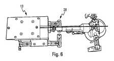
さらに、各々のアクチュエータ5の長さを測定するために、アクチュエータの長さが、各々のアクチュエータ5について、アクチュエータ5の枢動中心の間で、アクチュエータ5が最小長さの初期位置にある状態で、3D測定装置を使用して測定される。 Further, in order to measure the length of each actuator 5, the length of the actuator is set so that the actuator 5 is in the initial position of the minimum length between the pivot centers of the actuator 5 for each actuator 5. , Measured using a 3D measuring device.
より具体的には、図5に示されるように、2つのボール(例えば、セラミックまたは他の材料)の中心の間の距離が、アクチュエータ5が原点(脚の長さ)にあるときに、3D測定装置27を使用して測定される。 More specifically, as shown in FIG. 5, the distance between the centers of two balls (eg, ceramic or other material) is 3D when the actuator 5 is at the origin (leg length). It is measured using the measuring device 27.
この設備の下側の枢支は、ヘキサポッドのベースおよびキャリッジに取り付けられる枢支と同一のやり方で維持される。ボールは、例えば接着によって固定される。アクチュエータの先端の軸は、3つの中心に維持され、アクチュエータに、その初期位置において、並進ステージによって定められる軸に従うばねによって加えられる20Nの力が加えられる。上側の枢支ボールは、アクチュエータの先端の枢支カップに配置される。これは、測定段階における固定を保証するばねシステムによって維持される。 The lower pivot of this equipment is maintained in the same manner as the pivot attached to the base and carriage of the hexapod. The balls are fixed, for example, by gluing. The axis at the tip of the actuator is maintained at three centers and in its initial position a force of 20 N is applied to the actuator by a spring that follows the axis defined by the translational stage. The upper pivot ball is placed in the pivot cup at the tip of the actuator. This is maintained by a spring system that guarantees fixation during the measurement phase.
測定は、4つの連続するステップ、すなわち
・下側のボール(アクチュエータは組み立てられていない)の中心位置を測定し、支持プレートの角部の位置を追跡するステップ、
・アクチュエータを組み立て、上側のボールを位置決めするステップ、
・上側のボールの中心位置を測定するステップ、および
・(設備へのアクチュエータの配置の際に移動していないことを確認するために)プレートの角部の位置を検証するステップ
にて実施される。The measurement consists of four consecutive steps: -Measuring the center position of the lower ball (actuator is not assembled) and tracking the position of the corners of the support plate,
・ Steps to assemble the actuator and position the upper ball,
-Measured the center position of the upper ball, and-Verified the position of the corners of the plate (to ensure that it did not move when placing the actuator in the equipment). ..
この場合において、計算ユニット14は、アクチュエータ5の長さの位置の測定値を対応する理論値と比較し、アクチュエータの長さ誤差の補償マトリクスを作成する。 In this case, the
さらに、各々のアクチュエータ5のそれぞれの経路に沿った位置決め誤差を測定するために、図6に示される装置28を使用することが好ましい。 Further, it is preferable to use the device 28 shown in FIG. 6 to measure the positioning error along each path of each actuator 5.
この場合、計算ユニット14は、アクチュエータの位置決め誤差の測定値を用いて、位置決め誤差の補償マトリクスを作成する。 In this case, the
したがって、本発明の実施は、2つの段階、すなわち
・上述のとおりの種々の測定が実施され、次いで好ましくは補償マトリクスの形態の誤差(または、相違)の計算が実行される第1の段階と、
・ヘキサポッド2が通常どおりに使用されて標準的な動作を実行する第2の段階と
を有する。この場合において、計算された誤差(または、相違)は、これらの誤差を補償する目的において、これらの誤差を固定のベース3に関する可動キャリッジ7の移動を決定するときに考慮する制御ユニット6(または、コントローラ)に、1つ以上の標準的なアルゴリズムにて前もって統合される。Therefore, the practice of the present invention is carried out in two steps: the first step in which the various measurements as described above are carried out, and then preferably the calculation of the error (or difference) in the form of the compensation matrix is carried out. ,
Hexapod 2 has a second stage in which it is used normally and performs standard operations. In this case, the calculated errors (or differences) are taken into account when determining the movement of the movable carriage 7 with respect to the fixed base 3 for the purpose of compensating for these errors. , Controller) in advance with one or more standard algorithms.
これにより、可動キャリッジ7とベース3との間のきわめて正確な制御された移動を有するヘキサポッド2がもたらされる。 This results in a hexapod 2 with very precise controlled movement between the movable carriage 7 and the base 3.
Claims (9)
Translated fromJapanese・6つの独立した制御可能な直動アクチュエータ(5)を備えた駆動アセンブリ(4)と、
・前記駆動アセンブリ(4)のための制御ユニット(6)と、
・前記駆動アセンブリ(4)によって前記ベース(3)に接続されたプラットフォーム(8)を備える可動キャリッジ(7)と
を少なくとも備えており、
前記駆動アセンブリ(4)の前記アクチュエータ(5)の各々は、長手方向における第1の端部(5A)によって前記ベース(2)に第1のヒンジ(9A)によって連結され、長手方向における第2の端部(5B)によって前記キャリッジ(7)に第2のヒンジ(9B)によって連結され、前記6つのアクチュエータ(5)は、前記ベース(3)上の6つの枢動中心と、前記キャリッジ(7)上の6つの枢動中心とを定めているヘキサポッド(2)について、該ヘキサポッドの精度誤差を補償するための方法であって、
・前記ヘキサポッド(2)の幾何学的および位置決め誤差を測定するステップであって、
前記キャリッジ(7)上と前記ベース(3)上の前記枢動中心の位置決め誤差を決定するために、前記キャリッジ(7)上の各々の枢動中心および前記ベース(3)上の各々の枢動中心の位置を測定し、前記アクチュエータ(5)の長さ誤差を決定するために、各々のアクチュエータ(5)の長さを測定することと、そして
各々のアクチュエータ(5)のそれぞれの経路に沿って当該各々のアクチュエータ(5)の位置決め誤差を測定すること、を含み、
ここで、前記キャリッジ(7)上の各々の枢動中心および前記ベース(3)上の各々の枢動中心の位置を測定することが、ボール(23)を前記枢動中心の位置において前記ベース(3)に固定することと、前記ベース(3)を調整用プレート(24)に固定することと、前記ボール(23)の位置を3D測定装置を利用して測定することとを含み、そしてまた、前記ボール(25)を前記枢動中心の位置において前記キャリッジ(7)に固定することと、前記キャリッジ(7)を調整用プレート(26)に固定することと、前記ボール(23)の位置を3D測定装置を利用して測定することとを含むものである、
前記測定するステップと、
・前記側定するステップにおける測定から誤差補償値を計算するステップと、そして
・前記ヘキサポッド(2)の使用時に前記ヘキサポッド(2)の前記制御ユニット(6)に前記誤差補償値を適用するステップと、
を含むことを特徴とする方法。・ Fixed base (3) and
A drive assembly (4) with six independently controllable linear actuators (5) and
-The control unit (6) for the drive assembly (4) and
It includes at least a movable carriage (7) with a platform (8) connected to the base (3) by the drive assembly (4).
Each of the actuators (5) of the drive assembly (4) is connected to the base (2) by a first end (5A) in the longitudinal direction by a first hinge (9A) and a second in the longitudinal direction. The six actuators (5) are connected to the carriage (7) by a second hinge (9B) by an end (5B) of the six actuators (5) with six pivot centers on the base (3) and the carriage ( 7) Regarding the hexapod (2) that defines the above six pivot centers, this is a method for compensating for the accuracy error of the hexapod.
-A step of measuring the geometrical and positioning error of the hexapod (2).
Each pivot center on the carriage (7) and each pivot on the base (3)to determine the positioning error of the pivot center on the carriage (7) and the base (3). the position of the dynamic center was measured,to determine the length error of the actuator (5),and it measures the length of each of the actuators(5), and the respective path of each of the actuators (5) measuring the positioning errorof the each of the actuators (5) along,only including,
Here, measuring the position of each pivot center on the carriage (7) and each pivot center on the base (3) causes the ball (23) to be positioned at the pivot center. It includes fixing to (3), fixing the base (3) to the adjusting plate (24), and measuring the position of the ball (23) using a 3D measuring device, and Further, fixing the ball (25) to the carriage (7) at the position of the pivot center, fixing the carriage (7) to the adjusting plate (26), and fixing the ball (23) to the adjusting plate (26). It includes measuring the position using a 3D measuring device.
The step to measure and
- andLuz step to calculate an error compensation value from the measurement in said stepof side constant,and the said error compensation value the control unit (6) of the hexapod (2) when using the & the hexapod (2) applied andLuz step be,
A method characterized by including.
・前記キャリッジ(7)上の各々の枢動中心および前記ベース(3)上の各々の枢動中心の位置を直接測定することと、
・前記アクチュエータ(5)の長さ誤差を決定するために各々のアクチュエータ(5)の長さを直接測定することと
を同時に行うことからなる、ことを特徴とする請求項1に記載の方法。Measuring the position of each pivot center on the carriage (7) and each pivot center on the base (3)
-Directly measuring the position of each pivot center on the carriage (7) and each pivot center on the base (3).
The method according to claim 1, wherein the length of each actuator (5) is directly measured in order to determine the length error of the actuator (5) at the same time.
・6つの独立した制御可能な直動アクチュエータ(5)を備えた駆動アセンブリ(4)と、
・前記駆動アセンブリ(4)のための制御ユニット(6)と、
・前記駆動アセンブリによって前記ベース(3)に連結されたプラットフォーム(8)を備える可動キャリッジ(7)と
を少なくとも備えており、
前記駆動アセンブリ(4)の前記アクチュエータ(5)の各々は、長手方向における第1の端部(5A)によって前記ベース(2)に第1のヒンジ(9A)によって連結され、長手方向における第2の端部(5B)によって前記キャリッジ(7)に第2のヒンジ(9B)によって連結され、前記6つのアクチュエータ(5)は、前記ベース(3)上の6つの枢動中心と、前記キャリッジ(7)上の6つの枢動中心とを定めているヘキサポッド(2)について、該ヘキサポッドの精度誤差を補償するためのシステムであって、
・前記ヘキサポッド(2)の幾何学的および位置決め誤差を決定するように構成され、
前記枢動中心の位置決め誤差を決定するために、前記キャリッジ(7)上の各々の枢動中心および前記ベース(3)上の各々の枢動中心の位置を測定するとともに、前記アクチュエータ(5)の長さ誤差を決定するために、各々のアクチュエータ(5)の長さを測定するように構成された第1の測定アセンブリ(11、12)と、
各々のアクチュエータ(5)のそれぞれの経路に沿った位置決め誤差を測定するように構成された第2の測定アセンブリ(13)と
を備えている測定システム(10)と、
・前記測定から、前記ヘキサポッド(2)の使用時に前記ヘキサポッド(2)の前記制御ユニット(6)に適用される誤差補償値を計算するように構成された計算ユニット(14)と
を備えることを特徴とするシステム(1)。・ Fixed base (3) and
A drive assembly (4) with six independently controllable linear actuators (5) and
-The control unit (6) for the drive assembly (4) and
It includes at least a movable carriage (7) with a platform (8) connected to the base (3) by the drive assembly.
Each of the actuators (5) of the drive assembly (4) is connected to the base (2) by a first end (5A) in the longitudinal direction by a first hinge (9A) and a second in the longitudinal direction. The six actuators (5) are connected to the carriage (7) by a second hinge (9B) by an end (5B) of the six actuators (5) with six pivot centers on the base (3) and the carriage ( 7) Regarding the hexapod (2) that defines the above six pivot centers, this is a system for compensating for the accuracy error of the hexapod.
Configured to determine the geometric and positioning errors of the hexapod (2)
In order to determine the positioning error of the pivot center, the position of each pivot center on the carriage (7) and each pivot center on the base (3) is measured, and the actuator (5) A first measuring assembly (11, 12) configured to measure the length of each actuator (5) to determine the length error of the
A measurement system (10) comprising a second measurement assembly (13) configured to measure the positioning error along the respective path of each actuator (5).
A calculation unit (14) configured to calculate an error compensation value applied to the control unit (6) of the hexapod (2) when the hexapod (2) is used from the measurement. A system characterized by (1).
・前記枢動中心の位置決め誤差を決定するために、前記キャリッジ(7)上の各々の枢動中心および前記ベース(3)上の各々の枢動中心の位置を測定するように構成された測定アセンブリ(11)と、
・各々のアクチュエータ(5)の長さを測定するように構成された第2の測定アセンブリ(12)と
を備える、ことを特徴とする請求項8に記載のシステム。The first measurementassembly (11, 12)
-Measurements configured to measure the position of each pivot center on the carriage (7) and each pivot center on the base (3) to determine the positioning error of the pivot center. Assembly (11) and
8. The system of claim 8, comprising a second measuring assembly (12) configured to measure the length of each actuator (5).
Applications Claiming Priority (3)
| Application Number | Priority Date | Filing Date | Title |
|---|---|---|---|
| FR1559795 | 2015-10-15 | ||
| FR1559795AFR3042590B1 (en) | 2015-10-15 | 2015-10-15 | METHOD AND SYSTEM FOR PRECISION ERROR COMPENSATION OF A HEXAPODE |
| PCT/FR2016/052552WO2017064392A1 (en) | 2015-10-15 | 2016-10-05 | Method and system for compensating for accuracy errors of a hexapod |
Publications (2)
| Publication Number | Publication Date |
|---|---|
| JP2019500581A JP2019500581A (en) | 2019-01-10 |
| JP6894432B2true JP6894432B2 (en) | 2021-06-30 |
Family
ID=55411477
Family Applications (1)
| Application Number | Title | Priority Date | Filing Date |
|---|---|---|---|
| JP2018519719AExpired - Fee RelatedJP6894432B2 (en) | 2015-10-15 | 2016-10-05 | Methods and systems for compensating for hexapod accuracy errors |
Country Status (7)
| Country | Link |
|---|---|
| US (1) | US10830582B2 (en) |
| EP (1) | EP3362765B1 (en) |
| JP (1) | JP6894432B2 (en) |
| KR (1) | KR20180074678A (en) |
| CN (1) | CN108369092B (en) |
| FR (1) | FR3042590B1 (en) |
| WO (1) | WO2017064392A1 (en) |
Families Citing this family (15)
| Publication number | Priority date | Publication date | Assignee | Title |
|---|---|---|---|---|
| GB2568459B (en) | 2017-10-13 | 2020-03-18 | Renishaw Plc | Coordinate positioning machine |
| CN109500814B (en)* | 2018-11-30 | 2020-08-14 | 北京精密机电控制设备研究所 | Full-dimensional ground physical verification system and method for space manipulator with variable load conditions |
| US11449021B2 (en) | 2018-12-17 | 2022-09-20 | Divergent Technologies, Inc. | Systems and methods for high accuracy fixtureless assembly |
| CN109955227B (en)* | 2019-04-04 | 2021-04-02 | 银河航天(北京)通信技术有限公司 | Pointing mechanism, mechanical arm and spacecraft |
| GB2582972B (en)* | 2019-04-12 | 2021-07-14 | Renishaw Plc | Coordinate positioning machine |
| CN110722540B (en)* | 2019-10-31 | 2021-04-06 | 北京机械设备研究所 | Three-degree-of-freedom platform driven by pneumatic artificial muscles |
| CN111660281B (en)* | 2020-06-04 | 2022-03-22 | 中国科学院长春光学精密机械与物理研究所 | Parallel robot assembling method and auxiliary tool thereof |
| JP7528563B2 (en)* | 2020-06-29 | 2024-08-06 | オムロン株式会社 | Robot joint structure |
| DE102020124136B4 (en) | 2020-09-16 | 2023-09-07 | Physik Instrumente (PI) GmbH & Co KG | Method and arrangement for calibrating parallel kinematics |
| CN113503813B (en)* | 2021-06-09 | 2023-05-02 | 北京航天控制仪器研究所 | Six-degree-of-freedom motion platform linear displacement positioning precision measurement and error compensation method |
| EP4375029A4 (en)* | 2021-07-19 | 2025-07-23 | Nsk Ltd | DRIVE DEVICE, METHOD FOR CONTROLLING THE DRIVE DEVICE, PARALLEL CONNECTION ROBOT AND METHOD FOR CONTROLLING A PARALLEL CONNECTION ROBOT |
| DE102021125193B4 (en) | 2021-09-29 | 2023-05-25 | Dr. Ing. H.C. F. Porsche Aktiengesellschaft | Method and device for operating a measuring device for a component |
| CN115431265B (en)* | 2022-08-19 | 2024-06-18 | 昆明理工大学 | A parallel robot error compensation method and system based on optimization algorithm |
| KR102782938B1 (en)* | 2022-12-05 | 2025-03-18 | 국립경국대학교 산학협력단 | Large range precision pose adjustment device |
| US12345371B2 (en)* | 2023-01-31 | 2025-07-01 | Council Of Scientific And Industrial Research | Three degrees of freedom (3DoFs) precision positioning wedge air bearing stage system (WABSS) |
Family Cites Families (18)
| Publication number | Priority date | Publication date | Assignee | Title |
|---|---|---|---|---|
| JPH0774964B2 (en)* | 1987-06-25 | 1995-08-09 | 日本鋼管株式会社 | Robot positioning error correction method |
| JPH10267603A (en)* | 1996-11-22 | 1998-10-09 | Eizou Nishimura | Position and attitude detector |
| EP1034066A1 (en)* | 1997-12-01 | 2000-09-13 | Giddings & Lewis | System and method for calibrating a hexapod positioning device |
| DE19818635C2 (en)* | 1998-04-25 | 2000-03-23 | Weck Manfred | Procedure for calibrating a parallel manipulator |
| JP3443030B2 (en)* | 1999-03-31 | 2003-09-02 | オークマ株式会社 | measuring device |
| GB0805021D0 (en)* | 2008-03-18 | 2008-04-16 | Renishaw Plc | Apparatus and method for electronic circuit manufacture |
| TW201015457A (en)* | 2008-10-03 | 2010-04-16 | Hon Hai Prec Ind Co Ltd | Robot state inspecting system |
| US8215199B2 (en)* | 2008-11-17 | 2012-07-10 | Marcroft Sacha L | Parallel kinematic positioning system |
| US9545697B2 (en)* | 2009-04-06 | 2017-01-17 | The Boeing Company | Automated hole generation |
| GB201003599D0 (en)* | 2010-03-04 | 2010-04-21 | Renishaw Plc | Measurement method and apparatus |
| CN102909728B (en)* | 2011-08-05 | 2015-11-25 | 鸿富锦精密工业(深圳)有限公司 | The vision correction methods of robot tooling center points |
| WO2014053670A1 (en)* | 2012-10-02 | 2014-04-10 | Avs Added Value Industrial Engineering Solutions, S.L. | Manipulator for an ultra-high-vacuum chamber |
| FR2997887B1 (en)* | 2012-11-14 | 2015-07-10 | Commissariat Energie Atomique | HEXAPODE SYSTEM |
| US20140150593A1 (en)* | 2012-12-05 | 2014-06-05 | Alio Industries, Inc. | Precision tripod motion system |
| US9279658B1 (en)* | 2013-03-14 | 2016-03-08 | Exelis, Inc. | System and method for setting up secondary reflective optic |
| GB2512059B (en)* | 2013-03-18 | 2016-08-31 | Rolls Royce Plc | An independently moveable machine tool |
| CN103968761A (en)* | 2014-05-28 | 2014-08-06 | 中科华赫(北京)科技有限责任公司 | Absolute positioning error correction method of in-series joint type robot and calibration system |
| US9928097B1 (en)* | 2015-09-14 | 2018-03-27 | VCE IP Holding Company LLC | Methods, systems, and computer readable mediums for defining and updating a virtual computing system comprising distributed resource components |
- 2015
- 2015-10-15FRFR1559795Apatent/FR3042590B1/ennot_activeExpired - Fee Related
- 2016
- 2016-10-05USUS15/767,571patent/US10830582B2/enactiveActive
- 2016-10-05WOPCT/FR2016/052552patent/WO2017064392A1/ennot_activeCeased
- 2016-10-05EPEP16790664.3Apatent/EP3362765B1/enactiveActive
- 2016-10-05KRKR1020187010099Apatent/KR20180074678A/ennot_activeCeased
- 2016-10-05JPJP2018519719Apatent/JP6894432B2/ennot_activeExpired - Fee Related
- 2016-10-05CNCN201680059563.5Apatent/CN108369092B/ennot_activeExpired - Fee Related
Also Published As
| Publication number | Publication date |
|---|---|
| WO2017064392A1 (en) | 2017-04-20 |
| EP3362765A1 (en) | 2018-08-22 |
| FR3042590B1 (en) | 2017-11-10 |
| FR3042590A1 (en) | 2017-04-21 |
| CN108369092B (en) | 2020-12-08 |
| JP2019500581A (en) | 2019-01-10 |
| US10830582B2 (en) | 2020-11-10 |
| CN108369092A (en) | 2018-08-03 |
| EP3362765B1 (en) | 2021-08-04 |
| US20180299267A1 (en) | 2018-10-18 |
| KR20180074678A (en) | 2018-07-03 |
Similar Documents
| Publication | Publication Date | Title |
|---|---|---|
| JP6894432B2 (en) | Methods and systems for compensating for hexapod accuracy errors | |
| RU2559611C2 (en) | Error correction device for cnc machines | |
| US5239855A (en) | Positional calibration of robotic arm joints relative to the gravity vector | |
| US7152456B2 (en) | Automated robotic measuring system | |
| US8214080B2 (en) | Method and device for the compensation of geometrical errors in machining machinery | |
| Rauf et al. | Experimental results on kinematic calibration of parallel manipulators using a partial pose measurement device | |
| CN105787200A (en) | Automatic butt assembling method for large part as well as system | |
| US8961010B2 (en) | C-arm x-ray system and method of compensation for C-arm deformations and oscillations | |
| KR20160001558A (en) | Robotic Arm System and Method for calibrating Parallelism of the Same | |
| CN105364924A (en) | robot zero calibration system and robot zero calibration method | |
| WO2023170166A1 (en) | System and method for calibration of an articulated robot arm | |
| US20160379863A1 (en) | Wafer gripper with non-contact support platform | |
| KR102035334B1 (en) | Method for measuring geometric errors of 4-axis machine tools | |
| JPH11114777A (en) | Method for controlling machine tool | |
| KR100997763B1 (en) | Positioning support and measuring device with same | |
| JP2020191445A (en) | Method for automatically stacking plate-shaped article to be stacked, in particular transformer core plate | |
| KR20190030819A (en) | Method of compensating geometric error of mobile machine and mobile machine for performing the same | |
| US6446349B1 (en) | Method and device for spatial positioning and alignment of a ball and socket joint | |
| KR102862340B1 (en) | 3D optical alignment system | |
| Chen et al. | Development of a hexapod laser-based metrology system for finer optical beam pointing control | |
| KR20250072129A (en) | 3D optical alignment system | |
| KR20130042367A (en) | Method for compensating position of measuring device on xy stage | |
| KR20220146856A (en) | A straight line transfer device capable of correcting a traveling route and a method for correcting the traveling route | |
| CZ25815U1 (en) | Device for redundant optical measurement and/or calibration of body position within a space | |
| WO2012007527A2 (en) | Methods and systems for detecting, setting, monitoring, determining, storing and compensating the spatial situation of a mobile unit |
Legal Events
| Date | Code | Title | Description |
|---|---|---|---|
| A621 | Written request for application examination | Free format text:JAPANESE INTERMEDIATE CODE: A621 Effective date:20191004 | |
| A977 | Report on retrieval | Free format text:JAPANESE INTERMEDIATE CODE: A971007 Effective date:20200624 | |
| A131 | Notification of reasons for refusal | Free format text:JAPANESE INTERMEDIATE CODE: A131 Effective date:20200715 | |
| A601 | Written request for extension of time | Free format text:JAPANESE INTERMEDIATE CODE: A601 Effective date:20201015 | |
| A521 | Request for written amendment filed | Free format text:JAPANESE INTERMEDIATE CODE: A523 Effective date:20201210 | |
| TRDD | Decision of grant or rejection written | ||
| A01 | Written decision to grant a patent or to grant a registration (utility model) | Free format text:JAPANESE INTERMEDIATE CODE: A01 Effective date:20210521 | |
| A61 | First payment of annual fees (during grant procedure) | Free format text:JAPANESE INTERMEDIATE CODE: A61 Effective date:20210603 | |
| R150 | Certificate of patent or registration of utility model | Ref document number:6894432 Country of ref document:JP Free format text:JAPANESE INTERMEDIATE CODE: R150 | |
| LAPS | Cancellation because of no payment of annual fees |