JP6891714B2 - Filter device - Google Patents
Filter deviceDownload PDFInfo
- Publication number
- JP6891714B2 JP6891714B2JP2017152930AJP2017152930AJP6891714B2JP 6891714 B2JP6891714 B2JP 6891714B2JP 2017152930 AJP2017152930 AJP 2017152930AJP 2017152930 AJP2017152930 AJP 2017152930AJP 6891714 B2JP6891714 B2JP 6891714B2
- Authority
- JP
- Japan
- Prior art keywords
- tip
- tube
- base end
- inner tube
- catheter
- Prior art date
- Legal status (The legal status is an assumption and is not a legal conclusion. Google has not performed a legal analysis and makes no representation as to the accuracy of the status listed.)
- Active
Links
- 230000002093peripheral effectEffects0.000claimsdescription17
- 229920003002synthetic resinPolymers0.000claimsdescription17
- 239000000057synthetic resinSubstances0.000claimsdescription17
- 230000003014reinforcing effectEffects0.000claimsdescription12
- 229910052751metalInorganic materials0.000claimsdescription5
- 239000002184metalSubstances0.000claimsdescription5
- 210000004204blood vesselAnatomy0.000description42
- 239000007788liquidSubstances0.000description8
- 230000037452primingEffects0.000description7
- -1polyethylenePolymers0.000description6
- 239000004952PolyamideSubstances0.000description4
- 239000008280bloodSubstances0.000description4
- 210000004369bloodAnatomy0.000description4
- 229920001971elastomerPolymers0.000description4
- 229920002647polyamidePolymers0.000description4
- 239000004743PolypropyleneSubstances0.000description3
- 229910000831SteelInorganic materials0.000description3
- 208000007536ThrombosisDiseases0.000description3
- 239000000806elastomerSubstances0.000description3
- 239000000463materialSubstances0.000description3
- 229920001155polypropylenePolymers0.000description3
- 229910001220stainless steelInorganic materials0.000description3
- 239000010959steelSubstances0.000description3
- 239000004698PolyethyleneSubstances0.000description2
- 230000017531blood circulationEffects0.000description2
- 238000010586diagramMethods0.000description2
- 230000000694effectsEffects0.000description2
- 230000003902lesionEffects0.000description2
- 239000000203mixtureSubstances0.000description2
- 229920000728polyesterPolymers0.000description2
- 229920000573polyethylenePolymers0.000description2
- 229920001343polytetrafluoroethylenePolymers0.000description2
- 239000004810polytetrafluoroethyleneSubstances0.000description2
- 239000010935stainless steelSubstances0.000description2
- 239000002033PVDF binderSubstances0.000description1
- 229920002614Polyether block amidePolymers0.000description1
- BZHJMEDXRYGGRV-UHFFFAOYSA-NVinyl chlorideChemical compoundClC=CBZHJMEDXRYGGRV-UHFFFAOYSA-N0.000description1
- HZEWFHLRYVTOIW-UHFFFAOYSA-N[Ti].[Ni]Chemical compound[Ti].[Ni]HZEWFHLRYVTOIW-UHFFFAOYSA-N0.000description1
- 230000004308accommodationEffects0.000description1
- 230000009471actionEffects0.000description1
- 229910045601alloyInorganic materials0.000description1
- 239000000956alloySubstances0.000description1
- 238000005452bendingMethods0.000description1
- 239000000560biocompatible materialSubstances0.000description1
- 230000000903blocking effectEffects0.000description1
- 230000008859changeEffects0.000description1
- 229920001577copolymerPolymers0.000description1
- 229920000840ethylene tetrafluoroethylene copolymerPolymers0.000description1
- 239000005038ethylene vinyl acetateSubstances0.000description1
- 229920000126latexPolymers0.000description1
- 230000004048modificationEffects0.000description1
- 238000012986modificationMethods0.000description1
- 229910001000nickel titaniumInorganic materials0.000description1
- 239000004745nonwoven fabricSubstances0.000description1
- 239000002504physiological saline solutionSubstances0.000description1
- 229920001200poly(ethylene-vinyl acetate)Polymers0.000description1
- 229920001083polybutenePolymers0.000description1
- 229920000098polyolefinPolymers0.000description1
- 229920006124polyolefin elastomerPolymers0.000description1
- 229920002635polyurethanePolymers0.000description1
- 239000004814polyurethaneSubstances0.000description1
- 229920003225polyurethane elastomerPolymers0.000description1
- 229920002981polyvinylidene fluoridePolymers0.000description1
- 229920005989resinPolymers0.000description1
- 239000011347resinSubstances0.000description1
- 230000004044responseEffects0.000description1
- 229920002379silicone rubberPolymers0.000description1
Images


Landscapes
- Media Introduction/Drainage Providing Device (AREA)
- Surgical Instruments (AREA)
Description
Translated fromJapanese本発明は、血管内に設置されるフィルタを有するフィルタ装置に関する。 The present invention relates to a filter device having a filter installed in a blood vessel.
従来より、血管の狭窄部分より末梢側への血流を遮断することなく、プラークや血栓の一部を捕捉するものとして、血管内に設定されるフィルタが知られている。カテーテル内に収縮姿勢で収容されたフィルタが、所望の位置においてカテーテルから押し出されることによって拡張姿勢に弾性的に復元して、血管内に留置される(特許文献1)。 Conventionally, a filter set in a blood vessel has been known as a filter for capturing a part of a plaque or a thrombus without blocking the blood flow from the narrowed portion of the blood vessel to the peripheral side. A filter housed in a catheter in a contracted posture is elastically restored to an expanded posture by being pushed out of the catheter at a desired position and placed in a blood vessel (Patent Document 1).
フィルタ装置において、カテーテルの先端には、先端チップが設けられている。先端チップは、カテーテルが血管へ導入されるときには、カテーテルの先端に連結された状態である。先端チップが、血管の内壁に沿って柔軟に変形することによって、カテーテルの先端が血管の内壁に直接に当接することが抑制されて、カテーテルが円滑に血管内へ導入される。しかしながら、先端チップ及びカテーテルの先端部分が湾曲したときに、先端チップとカテーテルの先端との間に隙間が生じ、その隙間においてカテーテルの先端の角が血管の内壁に当接することがある。カテーテルの先端の角が血管の内壁に当接すると、カテーテルの導入に負荷が生じたり、血管の内壁を傷つけたりするおそれがある。 In the filter device, a tip tip is provided at the tip of the catheter. The tip is in a state of being connected to the tip of the catheter when the catheter is introduced into the blood vessel. The tip tip flexibly deforms along the inner wall of the blood vessel, thereby suppressing the tip of the catheter from directly contacting the inner wall of the blood vessel, and the catheter is smoothly introduced into the blood vessel. However, when the tip tip and the tip portion of the catheter are curved, a gap is created between the tip tip and the tip of the catheter, and the corner of the tip of the catheter may abut against the inner wall of the blood vessel in the gap. If the corner of the tip of the catheter abuts on the inner wall of the blood vessel, the introduction of the catheter may be overloaded or the inner wall of the blood vessel may be damaged.
本発明は、前述された事情に鑑みてなされたものであり、その目的は、血管へ導入しやすく、血管の内壁を傷つけるおそれが低減されたフィルタ装置を提供することにある。 The present invention has been made in view of the above-mentioned circumstances, and an object of the present invention is to provide a filter device that can be easily introduced into a blood vessel and has a reduced risk of damaging the inner wall of the blood vessel.
(1) 本発明に係るフィルタ装置は、シャフトと、上記シャフトの先端部に設けられた先端チップと、上記シャフトに設けられており、拡張姿勢から収縮姿勢へ弾性的に変形可能なフィルタと、内部空間に上記シャフトが挿通されており、当該内部空間に収縮姿勢の上記フィルタが収容可能なカテーテルと、を具備する。上記カテーテルの先端部は、インナーチューブの外側にカバーチューブが積層されており、当該カバーチューブが当該インナーチューブの先端より上記カテーテルの軸線方向へ突出している。上記先端チップの基端部は、上記インナーチューブの先端から突出した上記カバーチューブの内部空間へ収容可能である。 (1) The filter device according to the present invention includes a shaft, a tip tip provided at the tip of the shaft, a filter provided on the shaft and elastically deformable from an expanded posture to a contracted posture. The shaft is inserted into the internal space, and the internal space is provided with a catheter capable of accommodating the filter in a contracted posture. A cover tube is laminated on the outside of the inner tube at the tip of the catheter, and the cover tube projects from the tip of the inner tube in the axial direction of the catheter. The base end portion of the tip tip can be accommodated in the internal space of the cover tube protruding from the tip end of the inner tube.
インナーチューブの先端から突出したカバーチューブの内部空間へ先端チップが収容されることによって、インナーチューブの先端と先端チップとの間が、カバーチューブによって覆われる。これにより、インナーチューブ及び先端チップが湾曲した状態において、インナーチューブの先端と先端チップとの間に隙間が生じても、当該隙間をカバーチューブが覆っていることによって、インナーチューブの先端が血管の内壁などに当接することが防止される。 By accommodating the tip tip in the internal space of the cover tube protruding from the tip of the inner tube, the space between the tip of the inner tube and the tip tip is covered by the cover tube. As a result, even if a gap is created between the tip of the inner tube and the tip in the state where the inner tube and the tip are curved, the cover tube covers the gap so that the tip of the inner tube becomes a blood vessel. It is prevented from coming into contact with the inner wall or the like.
(2) 好ましくは、上記カテーテルは、合成樹脂製のチューブに金属製の補強部材が設けられた本体を有しており、上記インナーチューブは、上記本体に連続して設けられた合成樹脂製のチューブであり、上記カバーチューブは、上記インナーチューブより薄肉の合成樹脂製のチューブである。 (2) Preferably, the catheter has a main body in which a metal reinforcing member is provided on a synthetic resin tube, and the inner tube is made of synthetic resin continuously provided on the main body. It is a tube, and the cover tube is a tube made of synthetic resin thinner than the inner tube.
上記構成によれば、補強部材によってカテーテルの剛性を高めるとともに、カテーテルの先端においてインナーチューブによって柔軟性を高めることができる。また、仮にカテーテルの先端面から補強部材が突出しても、インナーチューブによって、突出した補強部材が覆われる。また、カバーチューブはインナーチューブより柔軟性が高い。 According to the above configuration, the rigidity of the catheter can be increased by the reinforcing member, and the flexibility can be increased by the inner tube at the tip of the catheter. Further, even if the reinforcing member protrudes from the tip surface of the catheter, the protruding reinforcing member is covered by the inner tube. Also, the cover tube is more flexible than the inner tube.
(3) 好ましくは、上記インナーチューブは、基端部より先端部が柔軟である。 (3) Preferably, the inner tube has a more flexible tip than the base end.
上記構成によれば、インナーチューブの先端部が血管の湾曲などに柔軟に追従する。 According to the above configuration, the tip of the inner tube flexibly follows the curvature of the blood vessel.
(4) 好ましくは、上記先端チップの基端部は、基端へ向かってテーパ形状に縮径する円柱形状の縮径部を有する。 (4) Preferably, the base end portion of the tip has a cylindrical diameter-reduced portion that is tapered toward the base end.
上記構成によれば、先端チップの基端部が、カバーチューブの内部空間へ収容されやすい。 According to the above configuration, the base end portion of the tip tip is easily accommodated in the internal space of the cover tube.
(5) 好ましくは、上記先端チップの基端部は、上記縮径部より小径の小径部を有しており、上記縮径部と上記小径部との間に基端へ向く段差面を有しており、上記縮径部が、上記インナーチューブの先端から突出した上記カバーチューブの内部空間へ収容可能であり、上記小径部が、上記インナーチューブの内部空間へ収容可能であり、上記段差面が、上記インナーチューブの先端面に当接可能である。 (5) Preferably, the base end portion of the tip has a smaller diameter portion having a smaller diameter than the reduced diameter portion, and has a stepped surface facing the proximal end between the reduced diameter portion and the small diameter portion. The reduced diameter portion can be accommodated in the internal space of the cover tube protruding from the tip of the inner tube, and the small diameter portion can be accommodated in the internal space of the inner tube. However, it can come into contact with the tip surface of the inner tube.
上記構成によれば、先端チップの段差面とインナーチューブの先端面との当接によって、カバーチューブの内部空間へ収容された先端チップが、インナーチューブに対して位置決めされる。 According to the above configuration, the tip tip accommodated in the internal space of the cover tube is positioned with respect to the inner tube by the contact between the stepped surface of the tip tip and the tip surface of the inner tube.
(6) 好ましくは、上記先端チップの基端部の外周面に凹溝が設けられており、上記先端チップの基端部が上記カバーチューブの内部空間に収容された状態において、上記凹溝は、当該内部空間と外部とを連通する。 (6) Preferably, the groove is provided on the outer peripheral surface of the base end portion of the tip tip, and the groove is formed in a state where the base end portion of the tip tip is housed in the internal space of the cover tube. , Communicates the internal space with the outside.
上記構成によれば、凹溝を通じて、カバーチューブの内部空間から外部へプライミング液などの液体を流出することができる。 According to the above configuration, a liquid such as a priming liquid can flow out from the internal space of the cover tube to the outside through the concave groove.
(7) 好ましくは、上記凹溝は、上記軸線方向と交差する方向に間隔を空けて複数が配置されている。 (7) Preferably, a plurality of the concave grooves are arranged at intervals in a direction intersecting the axial direction.
上記構成によれば、カバーチューブの内部空間から外部へ液体が流出しやすくなる。 According to the above configuration, the liquid easily flows out from the internal space of the cover tube to the outside.
本発明に係るフィルタ装置は、血管へ導入しやすく、血管の内壁を傷つけるおそれが低減される。 The filter device according to the present invention can be easily introduced into a blood vessel, and the risk of damaging the inner wall of the blood vessel is reduced.
以下、本発明の好ましい実施形態を説明する。なお、本実施形態は本発明の一実施態様にすぎず、本発明の要旨を変更しない範囲で実施態様を変更できることは言うまでもない。 Hereinafter, preferred embodiments of the present invention will be described. Needless to say, the present embodiment is only one embodiment of the present invention, and the embodiments can be changed without changing the gist of the present invention.
[第1実施形態]
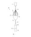
図1に示されるように、フィルタ装置10は、カテーテル11と、カテーテル11内においてカテーテル11の長手方向に沿って延出されたシャフト12(線材の一例)と、シャフト12に設けられた第1支持部13及び第2支持部14と、シャフト12の先端側に設けられたフィルタ15と、シャフト12の先端部に設けられた先端チップ16と、を具備する。フィルタ装置10は、カテーテル11の先端側から血管に挿入されて、フィルタ15がカテーテル11の先端から露出されることによって、血管の所望の位置にフィルタ15を拡張姿勢で留置するためのものである。なお、図1には、フィルタ15が拡張姿勢であるときのフィルタ装置10が示されている。[First Embodiment]
As shown in FIG. 1, the
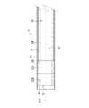
図3に示されるように、カテーテル11は、目的とする血管に挿入可能な円筒形状の部材である。カテーテル11は、本体31と、本体31の先端に接続されたインナーチューブ32と、本体31及びインナーチューブ32の外側に積層されたカバーチューブ33と、を有する。本体31は、合成樹脂製のチューブ34が、医療用ステンレスなどの金属線が網目に編み込まれた補強部材35によって補強されたものである。チューブ34の内部空間には、ディスタルチューブ37が設けられている。ディスタルチューブ37は、外径がチューブ34の内径にほぼ等しい管である。ディスタルチューブ37の内径は、シャフト12が挿通可能に設定されている。ディスタルチューブ37の先端面39は開口しており、ディスタルチューブ37の内部空間は、チューブ34の内部空間及びインナーチューブ32の内部空間と連続して、一つのルーメン20を形成している。ディスタルチューブ37の先端面39は、チューブ34の先端面38より基端側に位置する。ルーメン20において、ディスタルチューブ37の先端面39より先端側の空間が、フィルタ15の収容空間である。なお、図3においては、補強部材35の網目構造は詳細に示されておらず、管状の部材に簡略して示されている。また、図2,4においては、補強部材35が省略されている。 As shown in FIG. 3, the
図2に示されるように、ディスタルチューブ37の基端は、不図示のコネクタと接続されている。チューブ34及びカバーチューブ33の基端は、ディスタルチューブ37の途中までしか延びておらず、上記コネクタとは接続されていない。ディスタルチューブ37には、軸線方向101において、チューブ34及びカバーチューブ33の基端より基端側に貫通孔40が形成されている。貫通孔40は、ディスタルチューブ37の内部空間、すなわちルーメン20と外部とを連通している。シャフト12の基端側は、貫通孔40を通じてルーメン20から外部に延びている。 As shown in FIG. 2, the proximal end of the
インナーチューブ32は、本体31のチューブ34と外径及び内径がほぼ等しい合成樹脂製のチューブである。インナーチューブ32は、基端部32Aと先端部32Bとで、例えば合成樹脂の種類や組成が異なることによって、柔軟性が異なる。先端部32Bは、基端部32Aより柔軟である。なお、図3においては、基端部32Aと先端部32Bとの境界が破線で示されている。インナーチューブ32は、本体31の先端に同軸に接続されている。 The
インナーチューブ32、チューブ34、及びディスタルチューブ37としては、例えば、軟質塩化ビニル樹脂、ポリエチレンやポリプロピレンなどのポリオレフィン、エチレン−プロピレン共重合体やエチレン−酢酸ビニル共重合体、ポリプロピレンとポリブテンの混合物などのポリオレフィンエラストマー、ポリアミド、PTFEやETFEなどのフッ素樹脂、ポリエーテルブロックアミド、ポリアミドエラストマー、ポリエステルエラストマー、ポリウレタンエラストマー、フッ素樹脂系エラストマーなどの可撓性合成樹脂チューブ、シリコンゴム、ラテックスゴムなどのゴム製チューブなどが好適に用いられる。 Examples of the
カバーチューブ33は、本体31及びインナーチューブ32より薄肉のチューブである。カバーチューブ33の肉厚は、本体31の肉厚又はインナーチューブ32の肉厚に対して40から80%程度であることが好ましい。カバーチューブは、本体31及びインナーチューブ32の外側に積層されており、先端部分が、インナーチューブ32の先端より、カテーテル11の軸線方向101へ突出している。カバーチューブ33も、チューブ34やインナーチューブ32と同様の合成樹脂が採用できる。なお、カバーチューブ33は、少なくともインナーチューブ32の一部の外側に積層されて、インナーチューブ32の先端より突出していればよく、必ずしも本体31に積層されていたり、インナーチューブ32の全てに積層されていたりする必要はない。 The
カテーテル11は、全体として、血管の湾曲や分岐に沿って撓むことができる可撓性を有する。カテーテル11の外径や長さは、目的とする血管や病変の位置に応じて適宜設定される。なお、各図には現されていないが、カテーテル11の基端側には、カテーテル11を操作するときに把持されるハンドルなどの公知の構造が設けられている。 The
シャフト12は、カテーテル11のルーメン20において軸線方向101に沿って延出された線材である。シャフト12は、血管の湾曲や分岐に沿って撓むことができる可撓性と、基端側が軸線方向101へ押されたときに先端側が屈曲しない程度の剛性とを有する。シャフト12としては、ステンレス鋼線、ピアノ線、バネ用高張力鋼線、超弾性金属線などが好適に用いられる。シャフト12の外径や長さは、目的とする血管や病変の位置、カテーテル11の内径や長さに応じて適宜設定される。 The
フィルタ15は、フィルタ15は、第1支持部13及び第2支持部14を介してシャフト12に連結されている。フィルタ15は、拡張姿勢において紡錘形状の外形をなす複数のワイヤ21と、複数のワイヤ21の先端側に張られたシート22と、を有する。各ワイヤ21は、第1支持部13及び第2支持部14の間を軸線方向101に進行する螺旋形状をなしており、紡錘形状の周方向へ離間されている。シート22は、生体適合性材料の不織布又は織編物から形成された合成樹脂であり、血液等がシート22を通過可能であり、一方、血液中の血栓や血塊はシート22を通過不能である。紡錘形状をなす複数のワイヤ21の基端側には、シート22が張られていない。したがって、血液などは、拡張姿勢のフィルタ15において、紡錘形状をなすワイヤ21の基端側から各ワイヤ21の間を通過する。 The
フィルタ15は、カテーテル11のルーメン20に収容可能に弾性変形する。フィルタ15が弾性変形した姿勢(収縮姿勢)でカテーテル11のルーメン20にフィルタ15が収容可能となる。フィルタ15は、シャフト12をカテーテル11に対して相対的に先端側へ移動させる力が伝達されることによって、収縮姿勢においてカテーテル11の内面を摺動しながらカテーテル11の先端から外側へ移動可能である。フィルタ15がルーメン20から外部へ移動されると、フィルタ15が弾性復帰して円錐形状となる(拡張姿勢)。拡張姿勢において、フィルタ15の軸線方向101の中央部分の外径は、ルーメン20の内径より大きくなる。 The
ワイヤ21の素材は、例えば、ニッケル−チタン鋼線などの超弾性合金、バネ用高張力鋼線、ピアノ線などの金属線、ポリアミドやフッ素樹脂などの比較的剛性の高い合成樹脂などが好適に用いられる。シート22の素材は、例えば、ポリウレタンやポリエチレン、ポリエステル、ポリプロピレン、ポリアミド、ポリテトラフルオロエチレン、ポリフッ化ビニリデンなどの生体適合性のある合成樹脂が好適に用いられる。 The material of the
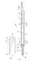
第1支持部13及び第2支持部14は、内部空間にシャフト12が挿通可能な管体である。第1支持部13及び第2支持部14は、例えばステンレス綱などからなる。第1支持部13は、シャフト12に対して軸線方向101へ移動可能である。第1支持部13は、フィルタの姿勢変化に応じて移動して、シャフト12に対する軸線方向101の位置が変化する。第2支持部14は、シャフト12に固定されており、シャフト12に対して回転せず、かつ軸線方向101に移動しない。第2支持部14の外径は、本体31のディスタルチューブ37の内径より大きい。したがって、第2支持部14は、ディスタルチューブ37の先端面39に当接可能であり、ディスタルチューブ37の内部空間には進入しない。 The
先端チップ16は、シャフト12の先端に固定されている。先端チップ16は、概ね円柱形状であって、先端部41と基端部42とに大別される。図2に示されるように、先端チップ16の基端部42は、インナーチューブ32の先端から突出したカバーチューブ33の内部空間へ収容可能である。先端部41は、先端へ向かって縮径する円柱形状である。先端部41と基端部42との境界は必ずしも確定する必要はないが、先端チップ16において、軸線方向101のほぼ中央に位置する外径が最大である部分が、先端部41と基端部42との概ね境界である。先端チップ16の最大外径は、カバーチューブ33の内径と同等ないし若干大きい。先端チップ16は、例えば、チューブ34やインナーチューブ32と同様の合成樹脂から成形される。 The
先端チップ16の基端部42は、基端へ向かってテーパ形状に縮径する円柱形状である。基端部42の外周面は、カバーチューブ33の先端を基端部42の最大外径の部分へ案内するガイドとして機能する。基端部42の軸線方向101に沿った長さは、カバーチューブ33がインナーチューブ32の先端から軸線方向101へ突出する長さより長い。基端部42の基端が最小外径であり、基端部42の基端の外径は、カバーチューブ33の内径より小さく、且つインナーチューブ32の内径より小さい。したがって、基端部42の一部は、カバーチューブ33の内部空間に収容可能であり、また、基端がインナーチューブ32の内部空間に進入可能である。基端部42の最大外径部分は、基端部42の先端側に位置している。基端部42の最大外径は、インナーチューブ32の内径より大きく、且つカバーチューブ33の内径と同等乃至若干大きい。 The
図1に示されるように、フィルタ15は、カテーテル11の先端から露出されることによって拡張姿勢となる。カテーテル11の基端側から先端側へ血液が流れる血管内において、フィルタ15が拡張姿勢にされることによって、血栓が拡張或いは切削などされたときに生じた細片が血液と共に流れても、フィルタ15によって捕捉される。 As shown in FIG. 1, the
図1に示された拡張姿勢のフィルタ15は、例えば、施術者がシャフト12が基端側へ引き戻すことによって、シャフト12と共にカテーテル11の先端へ移動し、図2に示されるように、カテーテル11の内部空間、すなわちインナーチューブ32の内部空間へ弾性変形されつつ収容される。インナーチューブ32の内部空間に収容されたフィルタ15は収縮姿勢となる。 The
図1に示されるように、フィルタ15が拡張姿勢であるときに、先端チップ16は、カテーテル11の先端から離間した位置にある。例えば前述されたようにして、フィルタ15がインナーチューブ32の内部空間へ収容されると、先端チップ16は、カテーテル11の先端部分に収容可能となる。詳細には、先端チップ16における基端部42が、カバーチューブ33の内部空間へ進入し、さらに基端部42の基端がインナーチューブ32の内部空間へ進入して収容される。 As shown in FIG. 1, the
基端部42は、外周面がカバーチューブ33の先端に当接して、カバーチューブ33の先端を、基端部42の最大外径の部分へ向かって案内する。そして、カバーチューブ33は、先端チップ16の外周面を覆うようにして、先端チップ16と密接する。基端部42の基端がインナーチューブ32に進入すると、インナーチューブ32の柔軟性によって、基端部42の外周面が、インナーチューブ32の先端部分を圧縮したり、内部空間を外側へ若干拡張したりするが、第2支持部14がディスタルチューブ37の先端面39と当接することによって、シャフト12を基端側へ引き戻す施術者に抵抗力を伝達する。これにより、施術者は、先端チップ16の基端部42が、カテーテル11の先端部分に収容されたことを感知する。 The outer peripheral surface of the
フィルタ装置10が血管内へ挿入されるときは、フィルタ装置10は、図2に示されるように、フィルタ15がカテーテル11に収容された収縮姿勢にあり、また、先端チップ16の基端部42がカテーテル11の先端部分に収容された状態にある。 When the
フィルタ装置10の先端、すなわち先端チップ16が血管の湾曲部分を進行すると、図4に示されるように、先端チップ16は、湾曲しつつ血管の湾曲外側の内壁を摺動する。また、カテーテル11も先端チップ16に追従して血管の湾曲に沿って湾曲する。インナーチューブ32の先端面36の外側はカバーチューブ33が覆っているので、先端面36は、フィルタ装置10の外部へ露出されない。したがって、先端面36の外縁であるインナーチューブ32の隅部が血管の内壁に当接したり摺動したりすることが防止される。 When the tip of the
[第1実施形態の作用効果]
第1実施形態に係るフィルタ装置10によれば、血管の湾曲に沿って先端チップ16及びカテーテル11が湾曲することによって血管への導入が容易である。また、インナーチューブ32の先端面36をカバーチューブ33が覆っているので、先端面36の外縁が血管の内壁を傷つけるおそれが低減される。[Action and effect of the first embodiment]
According to the
また、インナーチューブ32の本体31に補強部材35が設けられているので、カテーテル11の剛性が高められ、フィルタ装置10の導入に際してカテーテル11が屈曲したりすることが抑制される。また、本体31の先端に、補強部材35を有しないインナーチューブ32が設けられているので、カテーテル11の先端側が柔軟に湾曲しやすい。また、本体31に設けられた補強部材35が、カテーテル11の先端から外部へ突出することなどが抑制される。 Further, since the reinforcing
また、インナーチューブ32は、基端部32Aより先端部32Bが柔軟なので、先端部32Bが血管の湾曲などに柔軟に追従する。 Further, since the
[第2実施形態]
第2実施形態に係るフィルタ装置30は、先端チップ16に代えて先端チップ17が用いられており、カテーテル11がディスタルチューブ37を有していない点を除いて、第1実施形態に係るフィルタ装置10と同様の構成である。したがって、第1実施形態と同じ参照符号を付した部材は、同等の構成であるとして説明が省略される。[Second Embodiment]
In the
先端チップ17は、シャフト12の先端に固定されている。先端チップ17は、概ね円柱形状であって、先端部51と基端部52とに大別される。図6に示されるように、先端チップ17の基端部52は、インナーチューブ32の先端から突出したカバーチューブ33の内部空間へ収容可能である。先端部51は、先端へ向かって縮径する円柱形状である。先端部51と基端部52との境界は必ずしも確定する必要はないが、先端チップ17において、軸線方向101のほぼ中央に位置する外径が最大である部分が、先端部51と基端部52との概ね境界である。先端チップ17の最大外径は、カバーチューブ33の内径と同等ないし若干大きい。先端チップ17は、例えば、チューブ34やインナーチューブ32と同様の合成樹脂から成形される。 The
先端チップ17の基端部52は、基端へ向かってテーパ形状に縮径する円柱形状の縮径部53を有する。縮径部53の外周面は、カバーチューブ33の先端を基端部52の最大外径の部分へ案内するガイドとして機能する。縮径部53の軸線方向101に沿った長さは、カバーチューブ33がインナーチューブ32の先端から軸線方向101へ突出する長さより短い。縮径部53の基端が最小外径であり、縮径部53の基端の外径は、カバーチューブ33の内径より小さく、且つインナーチューブ32の内径より大きい。したがって、縮径部53は、カバーチューブ33の内部空間に収容可能であって、インナーチューブ32の内部空間には収容されない。 The
先端チップ17の基端部52は、縮径部53より基端側に位置しており、縮径部53の最小径より小さい外径の小径部54を有する。小径部54は、軸線方向101において一定の外径の円柱形状である。小径部54の外径は、インナーチューブ32の内径と同等ないし若干小さい。したがって、小径部54は、インナーチューブ32の内部空間に収容可能である。 The
先端チップ17の基端部52は、縮径部53の基端と小径部54の先端との間において基端へ向く段差面55を有する。縮径部53の基端及び小径部54の先端は、軸線方向101においてほぼ同じ位置に位置する。段差面55は、小径部54の先端から軸線方向101と直交する方向へ放射状に拡がる円環形状の平面である。先端チップ17の基端部52がカバーチューブ33の内部空間へ収容された状態において、段差面55は、インナーチューブ32の先端面36に当接可能である。 The
図5に示されるように、フィルタ15が拡張姿勢であるときに、先端チップ17は、カテーテル11の先端から離間した位置にある。例えば前述されたようにして、フィルタ15がインナーチューブ32の内部空間へ収容されると、先端チップ17は、カテーテル11の先端部分に収容可能となる。詳細には、先端チップ17における小径部54が、カバーチューブ33の内部空間へ進入し、さらにインナーチューブ32の内部空間へ進入して収容される。 As shown in FIG. 5, the
先端チップ17における縮径部53は、外周面がカバーチューブ33の先端に当接して、カバーチューブ33の先端を、基端部52の最大径の部分へ向かって案内する。そして、カバーチューブ33は、先端チップ17の外周面を覆うようにして、先端チップ17と密接する。縮径部53が完全にカバーチューブ33の内部空間へ進入すると、段差面55がインナーチューブ32の先端面36に当接する。先端面36と段差面55との当接によって、シャフト12を基端側へ引き戻す施術者に抵抗力を伝達する。これにより、施術者は、先端チップ17の基端部52が、カテーテル11の先端部分に収容されたことを感知する。 The outer peripheral surface of the reduced
フィルタ装置10が血管内へ挿入されるときは、フィルタ装置10は、図2に示されるように、フィルタ15がカテーテル11に収容された収縮姿勢にあり、また、先端チップ17の基端部52がカテーテル11の先端部分に収容された状態にある。 When the
フィルタ装置10の先端、すなわち先端チップ17が血管の湾曲部分を進行すると、図7に示されるように、先端チップ17は、湾曲しつつ血管の湾曲外側の内壁を摺動する。また、カテーテル11も先端チップ17に追従して血管の湾曲に沿って湾曲する。先端チップ17及びカテーテル11が湾曲することによって、カテーテル11の湾曲外側において、先端チップ17の段差面55とインナーチューブ32の先端面36との間に隙間50が生じることがある。 When the tip of the
先端チップ17の段差面55及びインナーチューブ32の先端面36の外側は、カバーチューブ33が覆っているので、隙間50は、フィルタ装置30の外部へ露出されない。したがって、段差面55の外縁である先端チップ17の隅部や、先端面36の外縁であるインナーチューブ32の隅部が血管の内壁に当接したり摺動したりすることが防止される。 Since the
第2実施形態に係るフィルタ装置30においても、第1実施形態に係るフィルタ装置10と同様の作用効果が奏される。 The
また、先端チップ17の基端部52は、基端へ向かってテーパ形状に縮径する円柱形状の縮径部53を有するので、先端チップ17の基端部52が、カバーチューブ33の内部空間へ収容されやすい。 Further, since the
また、先端チップ17の段差面55とインナーチューブ32の先端面36との当接によって、カバーチューブ33の内部空間へ収容された先端チップ17が、インナーチューブ32に対して軸線方向101の位置決めがなされる。 Further, due to the contact between the stepped
なお、基端部52が小径部54及び段差面55を有しておらず、縮径部53のみを有していてもよい。この場合、縮径部53は、カバーチューブ33の内部空間に収容されるが、縮径部53の基端面がインナーチューブ32の先端面に当接することによって、縮径部53がインナーチューブ32の内部空間へ進入しない。先端チップ17及びカテーテル11が湾曲することによって、縮径部53の基端面とインナーチューブ32の先端面36との間に、隙間50と同様の隙間が生じるおそれがあるが、この隙間をカバーチューブ33が覆っているので、段差面55の外縁や先端面36の外縁が血管の内壁を傷つけるおそれが低減される。 The
[第3実施形態]
第3実施形態に係るフィルタ装置60は、先端チップ16に代えて先端チップ61が用いられている点を除いて、第1実施形態に係るフィルタ装置10と同様の構成である。したがって、第1実施形態と同じ参照符号を付した部材は、同等の構成であるとして説明が省略される。[Third Embodiment]
The
図8(a)に示されるように、先端チップ61は、概ね円柱形状であって、先端部71と基端部72とを有する。先端チップ61の基端部72は、インナーチューブ32の先端から突出したカバーチューブ33の内部空間へ収容可能である。先端部71は、先端へ向かって縮径する円柱形状である。先端部71と基端部72との境界は必ずしも確定する必要はないが、先端チップ61において、軸線方向101のほぼ中央に位置する外径が最大である部分が、先端部71と基端部72との概ね境界である。本実施形態では、当該境界は、一定の内径の円柱形状である。先端チップ61の最大外径は、カバーチューブ33の内径と同等ないし若干大きい。先端チップ61は、例えば、チューブ34やインナーチューブ32と同様の合成樹脂から成形される。 As shown in FIG. 8A, the
先端チップ61の基端部72は、基端へ向かってテーパ形状に縮径する円柱形状である。基端部72の外周面は、カバーチューブ33の先端を基端部72の最大外径の部分へ案内するガイドとして機能する。基端部72の軸線方向101に沿った長さは、カバーチューブ33がインナーチューブ32の先端から軸線方向101へ突出する長さより長い。基端部72の基端が最小外径であり、基端部72の基端の外径は、カバーチューブ33の内径より小さく、且つインナーチューブ32の内径より小さい。したがって、基端部72の一部は、カバーチューブ33の内部空間に収容可能であり、また、基端がインナーチューブ32の内部空間に進入可能である。基端部72の最大外径部分は、基端部72の先端側に位置している。基端部72の最大外径は、インナーチューブ32の内径より大きく、且つカバーチューブ33の内径と同等乃至若干大きい。 The
先端チップ61の外周面73には、凹溝62が設けられている。凹溝62は、先端チップ61の外周面73において、軸線方向101に沿って延びている。図8(b)に示されるように、凹溝62は、先端チップ61の周方向102(軸線101と交差する方向の一例)に均等な間隔を空けて4つが配置されている。凹溝62は、外周面73から先端チップ61の径方向の内向きへ凹んでいる。凹溝62の断面形状は、概ね半円形状である。 A
凹溝62は、先端部71から基端部72に渡って延びている。図9に示されるように、先端チップ61の基端部72が、カバーチューブ33の内部空間に収容された状態において、凹溝62は、カバーチューブ33の内部空間と外部とを連通する。 The
先端チップ61には、軸線方向101に沿って先端チップ61を貫通する貫通孔63が設けられている。貫通孔63には、シャフト12が挿通され、先端チップ61は、シャフト12の外周面に対向する貫通孔63の内周面においてシャフト12に固定されている。また、シャフト12の先端は、先端チップ61の先端部71から突出している。 The
例えば、フィルタ装置60が使用される前に、生理食塩水等をプライミング液として、カテーテル11の内部空間にプライミング液を流通させる操作が行われる。この操作は、プライミングと称される。先端チップ61の基端部72が、カバーチューブ33の内部空間に収容可能であることにより、プライミング液の流通が悪くなることが想定される。これに対して、凹溝62を通じてプライミング液がカバーチューブ33やインナーチューブ32の内部空間から外部へ流出可能なので、プライミング液の流通が悪くなることを抑制できる。 For example, before the
なお、本実施形態では、凹溝62は、先端チップ61の基端部72から先端部71に渡って設けられているが、凹溝62は、基端部72が、カバーチューブ33の内部空間に収容された状態において、カバーチューブ33やインナーチューブ32の内部空間と外部とを連通可能な位置にあればよい。また、凹溝62は、必ずしも軸線方向101に沿って延びる必要はなく、軸線方向101と交差する方向へ延びていてもよいし、凹溝62が延びる方向が螺旋であったり蛇行したりしていてもよい。また、凹溝62の断面形状や数、配置は適宜変更されてもよいことは言うまでもない。また、第2実施形態に係る先端チップ17の外周面においても、凹溝62と同様の凹溝が設けてられてもよい。 In the present embodiment, the
また、先端チップ61が貫通孔63を有しておらず、第1実施形態と同様に、シャフト12の先端に先端チップ61が固定されていてもよい。また、先端チップ61からシャフト12の先端は必ずしも突出している必要はない。他方、第1実施形態の先端チップ16又は第2実施形態の先端チップ17が、第3実施形態と同様の貫通孔63を有しており、貫通孔63にシャフト12が挿通されて、先端チップ16、17にシャフト12が固定されていてもよい。また、シャフト12の先端が、先端チップ16、17の先端部41、51から突出していてもよい。 Further, the
[変形例]
また、前述された各実施形態では、フィルタ15が紡錘形状であるが、フィルタ15の外径や構成は、例えば、半球形状やドーム形状などのその他の形状であってもよいし、シート22を有さず、線材が網目に編み込まれたものなどであってもよい。[Modification example]
Further, in each of the above-described embodiments, the
また、前述された各実施形態に係るフィルタ装置10、30、60の使用は、血管にフィルタ15を導入するときに限定されず、既に血管に導入されたフィルタ15をカテーテル11を用いて回収するために使用されてもよい。 Further, the use of the
10,30,60・・・フィルタ装置
11・・・カテーテル
12・・・シャフト
15・・・フィルタ
16,17,61・・・先端チップ
31・・・本体
32・・・インナーチューブ
32A・・・基端部
32B・・・先端部
33・・・カバーチューブ
34・・・チューブ
35・・・補強部材
36・・・先端面
42,52,72・・・基端部
53・・・縮径部
54・・・小径部
55・・・段差面
62・・・凹溝10, 30, 60 ...
Claims (7)
Translated fromJapanese上記シャフトの先端部に設けられた先端チップと、
上記シャフトに設けられており、拡張姿勢から収縮姿勢へ弾性的に変形可能なフィルタと、
内部空間に上記シャフトが挿通されており、当該内部空間に収縮姿勢の上記フィルタが収容可能なカテーテルと、を具備しており、
上記カテーテルの先端部は、インナーチューブの外側にカバーチューブが積層されており、当該カバーチューブが当該インナーチューブの先端より上記カテーテルの軸線方向へ突出しており、
上記先端チップの基端部は、上記インナーチューブの先端から突出した上記カバーチューブの内部空間へ収容可能であるフィルタ装置。With the shaft
The tip provided at the tip of the shaft and the tip
A filter provided on the shaft that can be elastically deformed from an extended posture to a contracted posture,
The shaft is inserted into the internal space, and the internal space is provided with a catheter capable of accommodating the filter in a contracted posture.
A cover tube is laminated on the outside of the inner tube at the tip of the catheter, and the cover tube projects from the tip of the inner tube in the axial direction of the catheter.
The base end portion of the tip tip is a filter device that can be accommodated in the internal space of the cover tube protruding from the tip end of the inner tube.
上記インナーチューブは、上記本体に連続して設けられた合成樹脂製のチューブであり、
上記カバーチューブは、上記インナーチューブより薄肉の合成樹脂製のチューブである請求項1に記載のフィルタ装置。The catheter has a main body in which a metal reinforcing member is provided on a synthetic resin tube.
The inner tube is a tube made of synthetic resin continuously provided on the main body.
The filter device according to claim 1, wherein the cover tube is a tube made of a synthetic resin thinner than the inner tube.
上記縮径部と上記小径部との間に基端へ向く段差面を有しており、
上記縮径部が、上記インナーチューブの先端から突出した上記カバーチューブの内部空間へ収容可能であり、
上記小径部が、上記インナーチューブの内部空間へ収容可能であり、
上記段差面が、上記インナーチューブの先端面に当接可能である請求項4に記載のフィルタ装置。The base end portion of the tip has a smaller diameter portion having a smaller diameter than the reduced diameter portion.
It has a stepped surface facing the base end between the reduced diameter portion and the small diameter portion.
The reduced diameter portion can be accommodated in the internal space of the cover tube protruding from the tip of the inner tube.
The small diameter portion can be accommodated in the internal space of the inner tube.
The filter device according to claim 4, wherein the stepped surface can come into contact with the tip end surface of the inner tube.
上記先端チップの基端部が上記カバーチューブの内部空間に収容された状態において、上記凹溝は、当該内部空間と外部とを連通する請求項1から5のいずれかに記載のフィルタ装置。A concave groove is provided on the outer peripheral surface of the base end portion of the tip.
The filter device according to any one of claims 1 to 5, wherein in a state where the base end portion of the tip is housed in the internal space of the cover tube, the concave groove communicates the internal space with the outside.
Applications Claiming Priority (2)
| Application Number | Priority Date | Filing Date | Title |
|---|---|---|---|
| JP2017040018 | 2017-03-03 | ||
| JP2017040018 | 2017-03-03 |
Publications (2)
| Publication Number | Publication Date |
|---|---|
| JP2018143743A JP2018143743A (en) | 2018-09-20 |
| JP6891714B2true JP6891714B2 (en) | 2021-06-18 |
Family
ID=63589160
Family Applications (1)
| Application Number | Title | Priority Date | Filing Date |
|---|---|---|---|
| JP2017152930AActiveJP6891714B2 (en) | 2017-03-03 | 2017-08-08 | Filter device |
Country Status (1)
| Country | Link |
|---|---|
| JP (1) | JP6891714B2 (en) |
Families Citing this family (2)
| Publication number | Priority date | Publication date | Assignee | Title |
|---|---|---|---|---|
| JP7651827B2 (en)* | 2020-01-28 | 2025-03-27 | ニプロ株式会社 | Catheter Tips |
| WO2021153232A1 (en)* | 2020-01-28 | 2021-08-05 | ニプロ株式会社 | Leading-end tip for catheter |
Family Cites Families (4)
| Publication number | Priority date | Publication date | Assignee | Title |
|---|---|---|---|---|
| JPH044730Y2 (en)* | 1988-10-31 | 1992-02-12 | ||
| US6544279B1 (en)* | 2000-08-09 | 2003-04-08 | Incept, Llc | Vascular device for emboli, thrombus and foreign body removal and methods of use |
| JP5326313B2 (en)* | 2008-03-21 | 2013-10-30 | ニプロ株式会社 | Thrombus capture catheter |
| JP2012000327A (en)* | 2010-06-18 | 2012-01-05 | Kaneka Corp | Stent delivery catheter |
- 2017
- 2017-08-08JPJP2017152930Apatent/JP6891714B2/enactiveActive
Also Published As
| Publication number | Publication date |
|---|---|
| JP2018143743A (en) | 2018-09-20 |
Similar Documents
| Publication | Publication Date | Title |
|---|---|---|
| CN107427365B (en) | Expandable Sheath with Elastomeric Cross Section Section | |
| US20160113666A1 (en) | Methods and apparatus for treating pulmonary embolism | |
| JP4443278B2 (en) | Catheter with expansion body | |
| US9554904B2 (en) | Distal tip assembly for a heart valve delivery catheter | |
| US20150018859A1 (en) | Methods and apparatus for treating pulmonary embolism | |
| US20150265802A1 (en) | Catheter assembly | |
| JP2009528907A (en) | Stent delivery catheter | |
| JP5198258B2 (en) | Endoprosthesis delivery system | |
| JP6891714B2 (en) | Filter device | |
| JP5605636B2 (en) | Balloon catheter | |
| WO2013118362A1 (en) | Stent graft delivery device | |
| JPWO2018147449A1 (en) | Foreign matter removal device, foreign matter removal catheter, and foreign matter collection system | |
| JP2012061062A (en) | Catheter for delivering self-expanding prosthesis | |
| JP7078376B2 (en) | Recovery device | |
| JP2017064295A (en) | Catheter and stent delivery device | |
| WO2019039387A1 (en) | Intraluminal foreign object catching tool | |
| JP2016030035A (en) | catheter | |
| JP7102846B2 (en) | Stent delivery device | |
| JP6901872B2 (en) | Expansion catheter | |
| EP3459582A1 (en) | Catheter and catheter assembly | |
| US10327931B2 (en) | Pusher-assembly for an insertion system for a self-expandable vascular implant | |
| JP6650664B2 (en) | Filter device | |
| JP6749140B2 (en) | Medical treatment tool | |
| JP7293594B2 (en) | gastrointestinal stent | |
| JP7298598B2 (en) | stent delivery system |
Legal Events
| Date | Code | Title | Description |
|---|---|---|---|
| A621 | Written request for application examination | Free format text:JAPANESE INTERMEDIATE CODE: A621 Effective date:20200615 | |
| TRDD | Decision of grant or rejection written | ||
| A977 | Report on retrieval | Free format text:JAPANESE INTERMEDIATE CODE: A971007 Effective date:20210416 | |
| A01 | Written decision to grant a patent or to grant a registration (utility model) | Free format text:JAPANESE INTERMEDIATE CODE: A01 Effective date:20210427 | |
| A61 | First payment of annual fees (during grant procedure) | Free format text:JAPANESE INTERMEDIATE CODE: A61 Effective date:20210510 | |
| R150 | Certificate of patent or registration of utility model | Ref document number:6891714 Country of ref document:JP Free format text:JAPANESE INTERMEDIATE CODE: R150 | |
| R250 | Receipt of annual fees | Free format text:JAPANESE INTERMEDIATE CODE: R250 |