JP6891176B2 - Implantable nucleus pulposus prosthesis - Google Patents
Implantable nucleus pulposus prosthesisDownload PDFInfo
- Publication number
- JP6891176B2 JP6891176B2JP2018530671AJP2018530671AJP6891176B2JP 6891176 B2JP6891176 B2JP 6891176B2JP 2018530671 AJP2018530671 AJP 2018530671AJP 2018530671 AJP2018530671 AJP 2018530671AJP 6891176 B2JP6891176 B2JP 6891176B2
- Authority
- JP
- Japan
- Prior art keywords
- fillable
- enclosure
- lumen
- proximal
- plug
- Prior art date
- Legal status (The legal status is an assumption and is not a legal conclusion. Google has not performed a legal analysis and makes no representation as to the accuracy of the status listed.)
- Active
Links
- 239000007943implantSubstances0.000claimsdescription88
- 230000003014reinforcing effectEffects0.000claimsdescription59
- 239000000463materialSubstances0.000claimsdescription43
- 239000012530fluidSubstances0.000claimsdescription39
- 229920001296polysiloxanePolymers0.000claimsdescription17
- 230000002787reinforcementEffects0.000claimsdescription8
- 238000007789sealingMethods0.000claimsdescription8
- 239000002759woven fabricSubstances0.000claimsdescription8
- 230000001105regulatory effectEffects0.000claimsdescription5
- 238000002513implantationMethods0.000claimsdescription4
- 230000003750conditioning effectEffects0.000claimsdescription2
- 238000002347injectionMethods0.000claimsdescription2
- 239000007924injectionSubstances0.000claimsdescription2
- 230000013011matingEffects0.000claimsdescription2
- 238000005086pumpingMethods0.000claims1
- 238000000034methodMethods0.000description33
- 210000004940nucleusAnatomy0.000description15
- 239000002872contrast mediaSubstances0.000description6
- 238000004519manufacturing processMethods0.000description5
- 239000004744fabricSubstances0.000description4
- 238000003384imaging methodMethods0.000description4
- 238000002324minimally invasive surgeryMethods0.000description4
- 230000000149penetrating effectEffects0.000description4
- 238000011065in-situ storageMethods0.000description3
- 238000001746injection mouldingMethods0.000description3
- 229910052751metalInorganic materials0.000description3
- 239000002184metalSubstances0.000description3
- 229910001000nickel titaniumInorganic materials0.000description3
- HLXZNVUGXRDIFK-UHFFFAOYSA-Nnickel titaniumChemical compound[Ti].[Ti].[Ti].[Ti].[Ti].[Ti].[Ti].[Ti].[Ti].[Ti].[Ti].[Ni].[Ni].[Ni].[Ni].[Ni].[Ni].[Ni].[Ni].[Ni].[Ni].[Ni].[Ni].[Ni].[Ni]HLXZNVUGXRDIFK-UHFFFAOYSA-N0.000description3
- 210000001519tissueAnatomy0.000description3
- 230000003213activating effectEffects0.000description2
- TZCXTZWJZNENPQ-UHFFFAOYSA-Lbarium sulfateChemical compound[Ba+2].[O-]S([O-])(=O)=OTZCXTZWJZNENPQ-UHFFFAOYSA-L0.000description2
- 210000000988bone and boneAnatomy0.000description2
- 239000013536elastomeric materialSubstances0.000description2
- 239000000835fiberSubstances0.000description2
- 230000009969flowable effectEffects0.000description2
- 238000002594fluoroscopyMethods0.000description2
- 208000014674injuryDiseases0.000description2
- 238000003780insertionMethods0.000description2
- 230000037431insertionEffects0.000description2
- 238000009434installationMethods0.000description2
- 210000004492nuclear poreAnatomy0.000description2
- BASFCYQUMIYNBI-UHFFFAOYSA-NplatinumChemical compound[Pt]BASFCYQUMIYNBI-UHFFFAOYSA-N0.000description2
- 230000005855radiationEffects0.000description2
- 229920002379silicone rubberPolymers0.000description2
- 239000004945silicone rubberSubstances0.000description2
- 239000002904solventSubstances0.000description2
- 238000001356surgical procedureMethods0.000description2
- 230000008961swellingEffects0.000description2
- 229920000785ultra high molecular weight polyethylenePolymers0.000description2
- 208000008035Back PainDiseases0.000description1
- 208000008930Low Back PainDiseases0.000description1
- 208000012287ProlapseDiseases0.000description1
- 239000004699Ultra-high molecular weight polyethyleneSubstances0.000description1
- 208000027418Wounds and injuryDiseases0.000description1
- 239000006096absorbing agentSubstances0.000description1
- 230000002411adverseEffects0.000description1
- 230000032683agingEffects0.000description1
- 239000011324beadSubstances0.000description1
- 238000005452bendingMethods0.000description1
- 239000011248coating agentSubstances0.000description1
- 238000000576coating methodMethods0.000description1
- 238000004891communicationMethods0.000description1
- 229940039231contrast mediaDrugs0.000description1
- 230000006378damageEffects0.000description1
- 238000002059diagnostic imagingMethods0.000description1
- 208000037265diseases, disorders, signs and symptomsDiseases0.000description1
- 208000035475disorderDiseases0.000description1
- 238000010828elutionMethods0.000description1
- 230000035876healingEffects0.000description1
- 238000007654immersionMethods0.000description1
- 230000001788irregularEffects0.000description1
- 238000002386leachingMethods0.000description1
- 239000007788liquidSubstances0.000description1
- 238000012986modificationMethods0.000description1
- 230000004048modificationEffects0.000description1
- 238000000465mouldingMethods0.000description1
- 230000000704physical effectEffects0.000description1
- 229910052697platinumInorganic materials0.000description1
- 230000000452restraining effectEffects0.000description1
- 238000004062sedimentationMethods0.000description1
- 230000035939shockEffects0.000description1
- 238000004904shorteningMethods0.000description1
- 230000035882stressEffects0.000description1
- 230000008733traumaEffects0.000description1
- 238000012800visualizationMethods0.000description1
- 239000011800void materialSubstances0.000description1
- 238000003466weldingMethods0.000description1
Images


Classifications
- A—HUMAN NECESSITIES
- A61—MEDICAL OR VETERINARY SCIENCE; HYGIENE
- A61B—DIAGNOSIS; SURGERY; IDENTIFICATION
- A61B17/00—Surgical instruments, devices or methods
- A61B17/00234—Surgical instruments, devices or methods for minimally invasive surgery
- A—HUMAN NECESSITIES
- A61—MEDICAL OR VETERINARY SCIENCE; HYGIENE
- A61F—FILTERS IMPLANTABLE INTO BLOOD VESSELS; PROSTHESES; DEVICES PROVIDING PATENCY TO, OR PREVENTING COLLAPSING OF, TUBULAR STRUCTURES OF THE BODY, e.g. STENTS; ORTHOPAEDIC, NURSING OR CONTRACEPTIVE DEVICES; FOMENTATION; TREATMENT OR PROTECTION OF EYES OR EARS; BANDAGES, DRESSINGS OR ABSORBENT PADS; FIRST-AID KITS
- A61F2/00—Filters implantable into blood vessels; Prostheses, i.e. artificial substitutes or replacements for parts of the body; Appliances for connecting them with the body; Devices providing patency to, or preventing collapsing of, tubular structures of the body, e.g. stents
- A61F2/02—Prostheses implantable into the body
- A61F2/30—Joints
- A61F2/46—Special tools for implanting artificial joints
- A61F2/4603—Special tools for implanting artificial joints for insertion or extraction of endoprosthetic joints or of accessories thereof
- A61F2/4611—Special tools for implanting artificial joints for insertion or extraction of endoprosthetic joints or of accessories thereof of spinal prostheses
- A—HUMAN NECESSITIES
- A61—MEDICAL OR VETERINARY SCIENCE; HYGIENE
- A61F—FILTERS IMPLANTABLE INTO BLOOD VESSELS; PROSTHESES; DEVICES PROVIDING PATENCY TO, OR PREVENTING COLLAPSING OF, TUBULAR STRUCTURES OF THE BODY, e.g. STENTS; ORTHOPAEDIC, NURSING OR CONTRACEPTIVE DEVICES; FOMENTATION; TREATMENT OR PROTECTION OF EYES OR EARS; BANDAGES, DRESSINGS OR ABSORBENT PADS; FIRST-AID KITS
- A61F2/00—Filters implantable into blood vessels; Prostheses, i.e. artificial substitutes or replacements for parts of the body; Appliances for connecting them with the body; Devices providing patency to, or preventing collapsing of, tubular structures of the body, e.g. stents
- A61F2/02—Prostheses implantable into the body
- A61F2/30—Joints
- A61F2/44—Joints for the spine, e.g. vertebrae, spinal discs
- A61F2/441—Joints for the spine, e.g. vertebrae, spinal discs made of inflatable pockets or chambers filled with fluid, e.g. with hydrogel
- A—HUMAN NECESSITIES
- A61—MEDICAL OR VETERINARY SCIENCE; HYGIENE
- A61F—FILTERS IMPLANTABLE INTO BLOOD VESSELS; PROSTHESES; DEVICES PROVIDING PATENCY TO, OR PREVENTING COLLAPSING OF, TUBULAR STRUCTURES OF THE BODY, e.g. STENTS; ORTHOPAEDIC, NURSING OR CONTRACEPTIVE DEVICES; FOMENTATION; TREATMENT OR PROTECTION OF EYES OR EARS; BANDAGES, DRESSINGS OR ABSORBENT PADS; FIRST-AID KITS
- A61F2/00—Filters implantable into blood vessels; Prostheses, i.e. artificial substitutes or replacements for parts of the body; Appliances for connecting them with the body; Devices providing patency to, or preventing collapsing of, tubular structures of the body, e.g. stents
- A61F2/02—Prostheses implantable into the body
- A61F2/30—Joints
- A61F2/44—Joints for the spine, e.g. vertebrae, spinal discs
- A61F2/442—Intervertebral or spinal discs, e.g. resilient
- A—HUMAN NECESSITIES
- A61—MEDICAL OR VETERINARY SCIENCE; HYGIENE
- A61F—FILTERS IMPLANTABLE INTO BLOOD VESSELS; PROSTHESES; DEVICES PROVIDING PATENCY TO, OR PREVENTING COLLAPSING OF, TUBULAR STRUCTURES OF THE BODY, e.g. STENTS; ORTHOPAEDIC, NURSING OR CONTRACEPTIVE DEVICES; FOMENTATION; TREATMENT OR PROTECTION OF EYES OR EARS; BANDAGES, DRESSINGS OR ABSORBENT PADS; FIRST-AID KITS
- A61F2/00—Filters implantable into blood vessels; Prostheses, i.e. artificial substitutes or replacements for parts of the body; Appliances for connecting them with the body; Devices providing patency to, or preventing collapsing of, tubular structures of the body, e.g. stents
- A61F2/02—Prostheses implantable into the body
- A61F2/30—Joints
- A61F2/46—Special tools for implanting artificial joints
- A—HUMAN NECESSITIES
- A61—MEDICAL OR VETERINARY SCIENCE; HYGIENE
- A61F—FILTERS IMPLANTABLE INTO BLOOD VESSELS; PROSTHESES; DEVICES PROVIDING PATENCY TO, OR PREVENTING COLLAPSING OF, TUBULAR STRUCTURES OF THE BODY, e.g. STENTS; ORTHOPAEDIC, NURSING OR CONTRACEPTIVE DEVICES; FOMENTATION; TREATMENT OR PROTECTION OF EYES OR EARS; BANDAGES, DRESSINGS OR ABSORBENT PADS; FIRST-AID KITS
- A61F2/00—Filters implantable into blood vessels; Prostheses, i.e. artificial substitutes or replacements for parts of the body; Appliances for connecting them with the body; Devices providing patency to, or preventing collapsing of, tubular structures of the body, e.g. stents
- A61F2/02—Prostheses implantable into the body
- A61F2/30—Joints
- A61F2002/30001—Additional features of subject-matter classified in A61F2/28, A61F2/30 and subgroups thereof
- A61F2002/30003—Material related properties of the prosthesis or of a coating on the prosthesis
- A61F2002/3006—Properties of materials and coating materials
- A61F2002/30069—Properties of materials and coating materials elastomeric
- A—HUMAN NECESSITIES
- A61—MEDICAL OR VETERINARY SCIENCE; HYGIENE
- A61F—FILTERS IMPLANTABLE INTO BLOOD VESSELS; PROSTHESES; DEVICES PROVIDING PATENCY TO, OR PREVENTING COLLAPSING OF, TUBULAR STRUCTURES OF THE BODY, e.g. STENTS; ORTHOPAEDIC, NURSING OR CONTRACEPTIVE DEVICES; FOMENTATION; TREATMENT OR PROTECTION OF EYES OR EARS; BANDAGES, DRESSINGS OR ABSORBENT PADS; FIRST-AID KITS
- A61F2/00—Filters implantable into blood vessels; Prostheses, i.e. artificial substitutes or replacements for parts of the body; Appliances for connecting them with the body; Devices providing patency to, or preventing collapsing of, tubular structures of the body, e.g. stents
- A61F2/02—Prostheses implantable into the body
- A61F2/30—Joints
- A61F2002/30001—Additional features of subject-matter classified in A61F2/28, A61F2/30 and subgroups thereof
- A61F2002/30316—The prosthesis having different structural features at different locations within the same prosthesis; Connections between prosthetic parts; Special structural features of bone or joint prostheses not otherwise provided for
- A61F2002/30329—Connections or couplings between prosthetic parts, e.g. between modular parts; Connecting elements
- A61F2002/30462—Connections or couplings between prosthetic parts, e.g. between modular parts; Connecting elements retained or tied with a rope, string, thread, wire or cable
- A—HUMAN NECESSITIES
- A61—MEDICAL OR VETERINARY SCIENCE; HYGIENE
- A61F—FILTERS IMPLANTABLE INTO BLOOD VESSELS; PROSTHESES; DEVICES PROVIDING PATENCY TO, OR PREVENTING COLLAPSING OF, TUBULAR STRUCTURES OF THE BODY, e.g. STENTS; ORTHOPAEDIC, NURSING OR CONTRACEPTIVE DEVICES; FOMENTATION; TREATMENT OR PROTECTION OF EYES OR EARS; BANDAGES, DRESSINGS OR ABSORBENT PADS; FIRST-AID KITS
- A61F2/00—Filters implantable into blood vessels; Prostheses, i.e. artificial substitutes or replacements for parts of the body; Appliances for connecting them with the body; Devices providing patency to, or preventing collapsing of, tubular structures of the body, e.g. stents
- A61F2/02—Prostheses implantable into the body
- A61F2/30—Joints
- A61F2002/30001—Additional features of subject-matter classified in A61F2/28, A61F2/30 and subgroups thereof
- A61F2002/30316—The prosthesis having different structural features at different locations within the same prosthesis; Connections between prosthetic parts; Special structural features of bone or joint prostheses not otherwise provided for
- A61F2002/30535—Special structural features of bone or joint prostheses not otherwise provided for
- A61F2002/30581—Special structural features of bone or joint prostheses not otherwise provided for having a pocket filled with fluid, e.g. liquid
- A61F2002/30586—Special structural features of bone or joint prostheses not otherwise provided for having a pocket filled with fluid, e.g. liquid having two or more inflatable pockets or chambers
- A—HUMAN NECESSITIES
- A61—MEDICAL OR VETERINARY SCIENCE; HYGIENE
- A61F—FILTERS IMPLANTABLE INTO BLOOD VESSELS; PROSTHESES; DEVICES PROVIDING PATENCY TO, OR PREVENTING COLLAPSING OF, TUBULAR STRUCTURES OF THE BODY, e.g. STENTS; ORTHOPAEDIC, NURSING OR CONTRACEPTIVE DEVICES; FOMENTATION; TREATMENT OR PROTECTION OF EYES OR EARS; BANDAGES, DRESSINGS OR ABSORBENT PADS; FIRST-AID KITS
- A61F2/00—Filters implantable into blood vessels; Prostheses, i.e. artificial substitutes or replacements for parts of the body; Appliances for connecting them with the body; Devices providing patency to, or preventing collapsing of, tubular structures of the body, e.g. stents
- A61F2/02—Prostheses implantable into the body
- A61F2/30—Joints
- A61F2002/30001—Additional features of subject-matter classified in A61F2/28, A61F2/30 and subgroups thereof
- A61F2002/30316—The prosthesis having different structural features at different locations within the same prosthesis; Connections between prosthetic parts; Special structural features of bone or joint prostheses not otherwise provided for
- A61F2002/30535—Special structural features of bone or joint prostheses not otherwise provided for
- A61F2002/30593—Special structural features of bone or joint prostheses not otherwise provided for hollow
- A—HUMAN NECESSITIES
- A61—MEDICAL OR VETERINARY SCIENCE; HYGIENE
- A61F—FILTERS IMPLANTABLE INTO BLOOD VESSELS; PROSTHESES; DEVICES PROVIDING PATENCY TO, OR PREVENTING COLLAPSING OF, TUBULAR STRUCTURES OF THE BODY, e.g. STENTS; ORTHOPAEDIC, NURSING OR CONTRACEPTIVE DEVICES; FOMENTATION; TREATMENT OR PROTECTION OF EYES OR EARS; BANDAGES, DRESSINGS OR ABSORBENT PADS; FIRST-AID KITS
- A61F2/00—Filters implantable into blood vessels; Prostheses, i.e. artificial substitutes or replacements for parts of the body; Appliances for connecting them with the body; Devices providing patency to, or preventing collapsing of, tubular structures of the body, e.g. stents
- A61F2/02—Prostheses implantable into the body
- A61F2/30—Joints
- A61F2/44—Joints for the spine, e.g. vertebrae, spinal discs
- A61F2/442—Intervertebral or spinal discs, e.g. resilient
- A61F2002/4435—Support means or repair of the natural disc wall, i.e. annulus, e.g. using plates, membranes or meshes
- A—HUMAN NECESSITIES
- A61—MEDICAL OR VETERINARY SCIENCE; HYGIENE
- A61F—FILTERS IMPLANTABLE INTO BLOOD VESSELS; PROSTHESES; DEVICES PROVIDING PATENCY TO, OR PREVENTING COLLAPSING OF, TUBULAR STRUCTURES OF THE BODY, e.g. STENTS; ORTHOPAEDIC, NURSING OR CONTRACEPTIVE DEVICES; FOMENTATION; TREATMENT OR PROTECTION OF EYES OR EARS; BANDAGES, DRESSINGS OR ABSORBENT PADS; FIRST-AID KITS
- A61F2/00—Filters implantable into blood vessels; Prostheses, i.e. artificial substitutes or replacements for parts of the body; Appliances for connecting them with the body; Devices providing patency to, or preventing collapsing of, tubular structures of the body, e.g. stents
- A61F2/02—Prostheses implantable into the body
- A61F2/30—Joints
- A61F2/44—Joints for the spine, e.g. vertebrae, spinal discs
- A61F2/442—Intervertebral or spinal discs, e.g. resilient
- A61F2002/444—Intervertebral or spinal discs, e.g. resilient for replacing the nucleus pulposus
- A—HUMAN NECESSITIES
- A61—MEDICAL OR VETERINARY SCIENCE; HYGIENE
- A61F—FILTERS IMPLANTABLE INTO BLOOD VESSELS; PROSTHESES; DEVICES PROVIDING PATENCY TO, OR PREVENTING COLLAPSING OF, TUBULAR STRUCTURES OF THE BODY, e.g. STENTS; ORTHOPAEDIC, NURSING OR CONTRACEPTIVE DEVICES; FOMENTATION; TREATMENT OR PROTECTION OF EYES OR EARS; BANDAGES, DRESSINGS OR ABSORBENT PADS; FIRST-AID KITS
- A61F2/00—Filters implantable into blood vessels; Prostheses, i.e. artificial substitutes or replacements for parts of the body; Appliances for connecting them with the body; Devices providing patency to, or preventing collapsing of, tubular structures of the body, e.g. stents
- A61F2/02—Prostheses implantable into the body
- A61F2/30—Joints
- A61F2/44—Joints for the spine, e.g. vertebrae, spinal discs
- A61F2002/4495—Joints for the spine, e.g. vertebrae, spinal discs having a fabric structure, e.g. made from wires or fibres
- A—HUMAN NECESSITIES
- A61—MEDICAL OR VETERINARY SCIENCE; HYGIENE
- A61F—FILTERS IMPLANTABLE INTO BLOOD VESSELS; PROSTHESES; DEVICES PROVIDING PATENCY TO, OR PREVENTING COLLAPSING OF, TUBULAR STRUCTURES OF THE BODY, e.g. STENTS; ORTHOPAEDIC, NURSING OR CONTRACEPTIVE DEVICES; FOMENTATION; TREATMENT OR PROTECTION OF EYES OR EARS; BANDAGES, DRESSINGS OR ABSORBENT PADS; FIRST-AID KITS
- A61F2/00—Filters implantable into blood vessels; Prostheses, i.e. artificial substitutes or replacements for parts of the body; Appliances for connecting them with the body; Devices providing patency to, or preventing collapsing of, tubular structures of the body, e.g. stents
- A61F2/02—Prostheses implantable into the body
- A61F2/30—Joints
- A61F2/46—Special tools for implanting artificial joints
- A61F2002/4635—Special tools for implanting artificial joints using minimally invasive surgery
Landscapes
- Health & Medical Sciences (AREA)
- Engineering & Computer Science (AREA)
- Biomedical Technology (AREA)
- Orthopedic Medicine & Surgery (AREA)
- Transplantation (AREA)
- Life Sciences & Earth Sciences (AREA)
- General Health & Medical Sciences (AREA)
- Heart & Thoracic Surgery (AREA)
- Animal Behavior & Ethology (AREA)
- Public Health (AREA)
- Veterinary Medicine (AREA)
- Neurology (AREA)
- Vascular Medicine (AREA)
- Cardiology (AREA)
- Oral & Maxillofacial Surgery (AREA)
- Physical Education & Sports Medicine (AREA)
- Chemical & Material Sciences (AREA)
- Dispersion Chemistry (AREA)
- Surgery (AREA)
- Nuclear Medicine, Radiotherapy & Molecular Imaging (AREA)
- Medical Informatics (AREA)
- Molecular Biology (AREA)
- Prostheses (AREA)
- Surgical Instruments (AREA)
- Materials For Medical Uses (AREA)
Description
Translated fromJapanese関連出願の相互参照
本出願は、内容全体が参照により権利を放棄することなく特に本明細書に組み入れられる、2015年9月1日に出願された米国特許仮出願第62/212,950号の優先権を主張する。Cross-reference to related applications This application is the priority of US Patent Provisional Application No. 62 / 212,950 filed on September 1, 2015, in which the entire contents are incorporated herein by reference in particular. Insist.
背景
1.発明の分野
本出願は概して、椎間板を交換する方法および装置に関する。より具体的には、本出願は、最小侵襲手術を使用して、または経皮的に埋め込まれ得る埋込み可能な椎間板代替物およびそのような椎間板代替物/プロテーゼを製造する方法に関する。background
1. Scope of Invention The present application generally relates to methods and devices for exchanging intervertebral discs. More specifically, the present application relates to implantable disc substitutes that can be implanted using minimally invasive surgery or percutaneously and methods of producing such disc substitutes / prostheses.
2.関連技術の説明
よくある一般的な医学的問題は、外傷、加齢または他の障害によって生じる脊椎円板傷害による腰痛である。提案されてきた1つの治療法は、既存の髄核を除去し、それを、切開手術または最小侵襲手術を使用してインサイチューで形成される髄核プロテーゼと交換する方法である。1つの提案される方法は、以下の工程を含む:(i)インサイチューで硬化することができる流動可能な硬化性材料を収容するための、椎間板腔内の型、たとえばバルーンを提供する工程、(ii)型キャビティを流動可能な硬化性材料の供給源に接続するための、導管を提供する工程、(iii)流動可能な硬化性材料を型に送り込んで、キャビティを充填する工程、および(iv)硬化性材料を硬化させる工程。2. Description of related techniques A common common medical problem is low back pain due to spinal disc injuries caused by trauma, aging or other disorders. One treatment that has been proposed is to remove the existing nucleus pulposus and replace it with a nucleus pulposus prosthesis formed in situ using open surgery or minimally invasive surgery. One proposed method involves the following steps: (i) providing an intradiscal mold, eg, a balloon, to contain a fluid curable material that can be cured in situ. (Ii) The step of providing a conduit for connecting the mold cavity to the source of the flowable curable material, (iii) the step of feeding the flowable curable material into the mold and filling the cavity, and (iii). iv) The process of curing a curable material.
髄核プロテーゼをインサイチューで形成するための既存の技術は、納得のゆく臨床的受入れまたは商業的成功を達成していない。本発明者らによって確認された1つの課題は、一方では椎体終板および線維輪を含む椎骨要素と、他方では埋め込まれる要素との間の弾性率の実質的な差である。極端な曲げまたはねじれが起こっている間、特に高負荷ピーク時の衝撃または突然の椎間板内圧の増大を緩衝しないため、埋め込まれる材料の高い弾性率は不都合である。埋め込まれる椎間板材料と隣接組織との間の弾性率の大きな差はまた、椎体終板および隣接する骨の軟化を生じさせ、その結果、髄核インプラントの沈降をもたらし得る。インプラントの移動および脱出が起こることもある。 Existing techniques for forming the nucleus pulposus in situ have not achieved convincing clinical acceptance or commercial success. One issue identified by us is the substantial difference in elastic modulus between the vertebral elements, including the endplates and annulus fibrosus on the one hand, and the elements to be implanted on the other. The high modulus of the material to be implanted is inconvenient because it does not buffer the impact or sudden increase in disc pressure during extreme bending or twisting, especially during high load peaks. A large difference in elastic modulus between the implanted disc material and adjacent tissue can also result in softening of the vertebral endplate and adjacent bone, resulting in sedimentation of the nucleus pulposus implant. Implant movement and prolapse may occur.
したがって、改善された髄核インプラントが必要である。 Therefore, an improved nucleus pulposus implant is needed.
概要
別の例示的態様にしたがって、髄核代替装置を埋め込むためのキットは、脊椎インプラント装置およびインフレーションスタイラスを含む。充填可能な内側エンクロージャは、基端開口部を有する基端および末端開口部を有する末端を有する。充填可能な外側エンクロージャは基端および末端を有し、充填可能な内側および外側エンクロージャの基端どうしおよび末端どうしが結合されて、充填可能な外側エンクロージャが充填可能な内側エンクロージャを封入するようになっている。末端プラグが、充填可能な内側エンクロージャの末端の末端開口部を封止し、基端プラグが、充填可能な内側エンクロージャの基端の基端開口部を封止する。基端プラグは、内側エンクロージャへのアクセスを提供するための第一のルーメンと、外側のエンクロージャへのアクセスを提供するための第二のルーメンとを有する。インフレーションスタイラスは、基端プラグと嵌合するように適合され、インフレーションスタイラスは、流体を内側エンクロージャに送るための第一のルーメン、および流体を外側エンクロージャに送るための第二のルーメンを含む。Overview According to another exemplary embodiment, the kit for implanting a nucleus pulposus replacement device includes a spinal implant device and an inflation stylus. The fillable inner enclosure has a proximal end with a proximal opening and an end with a distal opening. The fillable outer enclosure has a base end and an end, and the base ends and ends of the fillable inner and outer enclosures are joined so that the fillable outer enclosure encloses the fillable inner enclosure. ing. The end plug seals the end opening at the end of the fillable inner enclosure, and the proximal plug seals the proximal opening at the proximal end of the fillable inner enclosure. The proximal plug has a first lumen to provide access to the inner enclosure and a second lumen to provide access to the outer enclosure. The inflation stylus is adapted to fit into the proximal plug, and the inflation stylus contains a first lumen for feeding the fluid to the inner enclosure and a second lumen for feeding the fluid to the outer enclosure.
いくつかの態様においては、補強バンドが充填可能な外側エンクロージャの周囲を包囲する。補強バンドは織物を含み得る。調節要素が環状補強バンドの中央ゾーンに結合されてもよい。少なくとも1つのプルストリングが環状補強バンドの縁に結合されてもよい。 In some embodiments, the reinforcing band surrounds the fillable outer enclosure. Reinforcing bands may include woven fabrics. The adjusting element may be coupled to the central zone of the annular reinforcing band. At least one pullstring may be attached to the edge of the annular reinforcing band.
いくつかの態様においては、送出しシースがインフレーションスタイラスを包囲し、送出しシースは、送出し位置から展開位置まで移動可能である。調節要素および少なくとも1つのプルストリングは送出しシースとインフレーションスタイラスとの間に配置されている。 In some embodiments, the delivery sheath surrounds the inflation stylus and the delivery sheath is movable from the delivery position to the deployment position. The adjusting element and at least one pullstring are located between the delivery sheath and the inflation stylus.
例示的態様にしたがって、脊椎インプラント装置は、充填可能な内側エンクロージャおよび充填可能な外側エンクロージャを含む。充填可能な内側エンクロージャは、基端開口部を有する基端および末端開口部を有する末端を有する。充填可能な外側エンクロージャは基端および末端を有し、充填可能な内側および外側エンクロージャの基端どうしおよび末端どうしが結合されて、充填可能な外側エンクロージャが充填可能な内側エンクロージャを実質的に封入するようになっている。末端プラグが、充填可能な内側エンクロージャの末端の末端開口部を封止し、基端プラグが、充填可能な内側エンクロージャの基端の基端開口部を封止する。基端プラグが、充填可能な内側エンクロージャの基端の基端開口部を封止する。基端プラグは、内側エンクロージャへのアクセスを提供するための第一のルーメンと、外側のエンクロージャへのアクセスを提供するための第二のルーメンとを有する。いくつかの態様において、内側エンクロージャへのアクセスを提供するための第一のルーメンは、埋込み後でも開いたままである。 According to an exemplary embodiment, the spinal implant device comprises a fillable inner enclosure and a fillable outer enclosure. The fillable inner enclosure has a proximal end with a proximal opening and an end with a distal opening. The fillable outer enclosure has a base end and an end, and the base ends and ends of the fillable inner and outer enclosures are joined together to substantially enclose the fillable inner enclosure. It has become like. The end plug seals the end opening at the end of the fillable inner enclosure, and the proximal plug seals the proximal opening at the proximal end of the fillable inner enclosure. The proximal plug seals the proximal opening at the proximal end of the fillable inner enclosure. The proximal plug has a first lumen to provide access to the inner enclosure and a second lumen to provide access to the outer enclosure. In some embodiments, the first lumen to provide access to the inner enclosure remains open after implantation.
いくつかの態様において、充填可能な内側および外側エンクロージャは一体の材料片を含む。 In some embodiments, the fillable inner and outer enclosures include an integral piece of material.
いくつかの態様において、基端プラグは、それぞれ内側および外側エンクロージャに流体を送るための第一および第二のルーメンを含むインフレーションスタイラスを受けるように適合されている。 In some embodiments, the proximal plug is adapted to receive an inflation stylus containing first and second lumens to deliver fluid to the inner and outer enclosures, respectively.
いくつかの態様においては、補強バンドが充填可能な外側エンクロージャの周囲を包囲する。補強バンドは織物を含み得る。調節要素が環状補強バンドの中央ゾーンに結合されてもよい。少なくとも1つのプルストリングが環状補強バンドの縁に結合されてもよい。 In some embodiments, the reinforcing band surrounds the fillable outer enclosure. Reinforcing bands may include woven fabrics. The adjusting element may be coupled to the central zone of the annular reinforcing band. At least one pullstring may be attached to the edge of the annular reinforcing band.
いくつかの態様において、外側エンクロージャは硬化性シリコーン材料を充填される。 In some embodiments, the outer enclosure is filled with a curable silicone material.
別の例示的態様にしたがって、線維輪によって包囲された髄核を有する椎間腔に補綴装置を埋め込む方法は、線維輪を貫通する工程;髄核を除去して除核椎間板腔を形成する工程;内側エンクロージャを形成する充填可能な内側エンクロージャと、充填可能な内側エンクロージャに結合された充填可能な外側エンクロージャとを有し、充填可能な外側エンクロージャが充填可能な内側エンクロージャを実質的に完全に包囲するような充填可能な椎間板インプラント装置を除核椎間板腔に挿入する工程;充填可能な内側エンクロージャを流体媒体で膨らませる工程;充填可能な外側エンクロージャを硬化性媒体で膨らませる工程;硬化性媒体を硬化させる工程;充填可能な内側エンクロージャから流体媒体を取り出す工程;および流体が充填可能な内側エンクロージャに出入りし得るように充填可能な内側エンクロージャを通気状態にしておく工程を含む。 According to another exemplary embodiment, the method of implanting a prosthesis into an intervertebral space with a nucleus pulposus surrounded by an annulus fibrosus is a step of penetrating the annulus fibrosus; a step of removing the nucleus pulposus to form a denuclearized intervertebral space. It has a fillable inner enclosure forming an inner enclosure and a fillable outer enclosure coupled to a fillable inner enclosure, the fillable outer enclosure substantially completely enclosing the fillable inner enclosure. Inserting a fillable intervertebral implant device into the denuclearized intervertebral space; inflating a fillable inner enclosure with a fluid medium; inflating a fillable outer enclosure with a curable medium; It includes the steps of curing; removing the fluid medium from the fillable inner enclosure; and keeping the fillable inner enclosure ventilated so that fluid can enter and exit the fillable inner enclosure.
いくつかの態様において、流体媒体は、実質的に非圧縮性の流体、たとえば造影剤を含む。 In some embodiments, the fluid medium comprises a substantially incompressible fluid, such as a contrast agent.
いくつかの態様においては、充填可能な椎間板インプラントの周囲を補強するための補強バンドが提供される。補強バンドは、除核椎間板腔に挿入され、充填可能な椎間板インプラントを受けるためのポケットを形成するように操作される。補強バンドは、補強バンドの下縁および補強バンドの上縁を引っ張って縁を除核椎間板腔の内部に向けて引っ張り;補強バンドの中央部分の調節要素を作動させて、この中央部分で環状補強バンドを除核椎間板腔の線維輪に向けて外に押すことによって操作され得る。補強バンドの下縁および上縁は、補強バンドの下縁および上縁に配置された下および上のプルストリングを使用することによって引っ張られ得る。調節要素は、可撓性のリボンを使用して環状補強バンドを線維輪に向けて外に押すことによって作動させ得る。プルストリングおよび可撓性のリボンは、充填可能な外側エンクロージャが充填されたのち、取り外され得る。 In some embodiments, a reinforcing band is provided to reinforce the perimeter of the fillable disc implant. The stiffening band is inserted into the denuclearized disc cavity and manipulated to form a pocket for receiving a fillable disc implant. The stiffening band pulls on the lower edge of the stiffening band and the upper edge of the stiffening band and pulls the edges towards the inside of the denuclearized disc cavity; it activates the adjustment element in the central part of the stiffening band to provide annular reinforcement at this central part. It can be manipulated by pushing the band out towards the annulus fibrosus of the denuclear disc cavity. The lower and upper edges of the stiffening band can be pulled by using lower and upper pull strings located on the lower and upper edges of the stiffening band. The adjusting element can be actuated by pushing the annular reinforcing band outward toward the annulus fibrosus using a flexible ribbon. The pullstring and flexible ribbon can be removed after the fillable outer enclosure has been filled.
さらに別の態様にしたがって、脊椎板インプラントのための補強バンドは、上縁、下縁、および上縁と下縁との間の中央ゾーンを有する織物バンドを含む。引っ張られたとき織物バンドの上縁を締め付けるための上ドローストリングが織物バンドの上縁に配置され、引っ張られたとき織物バンドの上縁を締め付けるための下ドローストリングが織物バンドの下縁に配置されている。中央ゾーンを拡張するための調節要素が中央ゾーンに配置されている。調節要素は金属リボンを含み得る。 According to yet another aspect, the reinforcing band for the spinal plate implant includes a woven band having an upper edge, a lower edge, and a central zone between the upper edge and the lower edge. An upper drawstring for tightening the upper edge of the fabric band when pulled is placed on the upper edge of the fabric band, and a lower drawstring for tightening the upper edge of the fabric band when pulled is placed on the lower edge of the fabric band. Has been done. Adjustment elements for expanding the central zone are located in the central zone. The adjusting element may include a metal ribbon.
用語「結合されている」とは、必ずしも直接的ではないが、接続されていることと定義される。単数形不定冠詞は、そうでないことを本開示が明示的に要求しない限り、1つまたは複数と定義される。用語「実質的に」、「およそ」および「約」は、当業者によって理解されるような、指定されるものの、必ずしもすべてではないが大部分(かつ、指定されるものを含む。たとえば、実質的に90°は90°を含み、実質的に平行は平行を含む)と定義される。任意の開示される態様において、用語「実質的に」、「およそ」および「約」は、指定されるものの「〜%以内」と言い換えられてもよい(%は0.1、1、5および10%を含む)。 The term "combined" is defined as being connected, though not necessarily directly. A singular indefinite article is defined as one or more unless expressly required by the present disclosure to do so. The terms "substantially", "approximately" and "about" are specified, but not necessarily all, (and include those specified, as understood by those skilled in the art, eg, substantially. 90 ° includes 90 °, and substantially parallel includes parallel). In any disclosed embodiment, the terms "substantially", "approximately" and "about" may be paraphrased as "within ~%" of what is specified (% is 0.1, 1, 5 and 10%). including).
用語「含む」(およびその任意の形、たとえば「含み」、「含んで」)、「有する」(およびその任意の形、たとえば「有し」、「有して」)、「包含する」(およびその任意の形、たとえば「包含し」、「包含して」)および「含有する」(およびその任意の形、たとえば「含有し」、「含有して」)は、非限定的連結動詞である。その結果、1つまたは複数の要素または特徴を「含む」、「有する」、「包含する」または「含有する」システムまたはシステムの構成部品は、そのような1つまたは複数の要素または特徴を所有するが、そのような要素または特徴のみを所有することに限定されない。同様に、1つまたは複数の工程を「含む」、「有する」、「包含する」または「含有する」方法は、そのような1つまたは複数の工程を所有するが、そのような1つまたは複数の工程のみを所有することに限定されない。加えて、「第一の」および「第二の」のような語は、構造または特徴を区別するためだけに使用され、様々な構造または特徴を特定の順序に限定するために使用されるものではない。 The terms "include" (and any form thereof, such as "include", "include"), "have" (and any form thereof, such as "have", "have"), "include" ( And any form thereof, such as "include", "include") and "contain" (and any form thereof, such as "contain", "contain") are nonfinite concatenated verbs. is there. As a result, a system or system component that "contains," "has," "includes," or "contains" one or more elements or features possesses such one or more elements or features. However, it is not limited to owning only such elements or features. Similarly, a method that "includes," "has," "includes," or "contains" one or more steps possesses such one or more steps, but one or more such steps. It is not limited to owning only a plurality of processes. In addition, terms such as "first" and "second" are used only to distinguish structures or features, and to limit various structures or features to a particular order. is not it.
ある特定のやり方で構成されている装置、システムまたは構成部品は、少なくともそのやり方で構成されているが、具体的に記載されたやり方以外のやり方で構成されることもできる。 A device, system or component configured in a particular manner is configured in at least that manner, but may be configured in a manner other than that specifically described.
システムおよび方法のいずれかの任意の態様は、記載された要素、特徴および/または工程のいずれかからなる、または本質的になることができる(それを含む/包含する/含有する/有する、のではなく)。したがって、請求項のいずれかにおいても、用語「〜からなる」または「〜から本質的になる」は、所与の請求項の範囲を、上記非限定的連結動詞を使用した場合の範囲から変更するために、上記非限定的連結動詞のいずれかに代えて用いることができる。 Any aspect of any of the systems and methods can consist of, or is essentially, of any of the described elements, features and / or steps (including / including / containing / having). not). Thus, in any of the claims, the term "consisting of" or "consisting of essentially" modifies the scope of a given claim from the scope of using the non-limiting concatenated verbs described above. Can be used in place of any of the above non-limiting connecting verbs.
本開示または態様の性質によって明示的に禁じられない限り、1つの態様の特徴は、記載または例示されないとしても、他の態様に適用され得る。 Unless expressly prohibited by the nature of the present disclosure or aspects, the features of one aspect may apply to other aspects, if not described or exemplified.
[本発明1001]
基端開口部を有する基端および末端開口部を有する末端を有する、充填可能な内側エンクロージャ;
基端および末端を有する、充填可能な外側エンクロージャであって、
該充填可能な内側および外側エンクロージャの該基端どうしが結合され、かつ該充填可能な内側および外側エンクロージャの該末端どうしが結合されて、該充填可能な内側エンクロージャを封入するようになっている、充填可能な外側エンクロージャ;
該充填可能な内側エンクロージャの該末端の該末端開口部を封止するための、末端プラグ;および
該充填可能な内側エンクロージャの該基端の該基端開口部を封止するための、基端プラグであって、
該充填可能な内側エンクロージャへのアクセスを提供するためのアクセスルーメンと、該充填可能な外側エンクロージャへのアクセスを提供するため開口部を有するレセプタクルとを有し、
該充填可能な内側エンクロージャへのアクセスを提供するための該アクセスルーメンが埋込み後でも開いたままであるように構成されている、基端プラグ
を含む、脊椎インプラント装置、ならびに
該基端プラグと嵌合するように適合されたインフレーションスタイラスであって、
該アクセスルーメンを通って移動可能に延びて該内側エンクロージャから流体を送りかつ取り出すための、調節可能な第一のルーメン;および
流体を該外側エンクロージャに送るための、第二のルーメン
を含む、インフレーションスタイラス
を含む、髄核代替装置を埋め込むためのキット。
[本発明1002]
充填可能な外側エンクロージャの周囲を包囲する補強バンドをさらに含む、本発明1001のキット。
[本発明1003]
補強バンドが織物を含む、本発明1002のキット。
[本発明1004]
環状補強バンドに結合された調節要素をさらに含む、本発明1002のキット。
[本発明1005]
環状補強バンドの縁に結合された少なくとも1つのプルストリングをさらに含む、本発明1004のキット。
[本発明1006]
少なくとも1つのプルストリングが補強バンド中の溝に縫い込まれている、本発明1005のキット。
[本発明1007]
インフレーションスタイラスを包囲する送出しシースをさらに含み、該送出しシースが送出し位置から展開位置まで移動可能である、本発明1005のキット。
[本発明1008]
調節要素および少なくとも1つのプルストリングが送出しシースとインフレーションスタイラスとの間に配置されている、本発明1007のキット。
[本発明1009]
充填可能な外側エンクロージャに注入するための硬化性シリコーン材料をさらに含む、本発明1001のキット。
[本発明1010]
硬化性シリコーン材料が5分以内に実質的に硬化する、本発明1009のキット。
[本発明1011]
基端開口部を有する基端および末端開口部を有する末端を有する、充填可能な内側エンクロージャ;
基端および末端を有する、充填可能な外側エンクロージャであって、
該充填可能な内側および外側エンクロージャの該基端どうしが結合され、かつ該充填可能な内側および外側エンクロージャの該末端どうしが結合されて、該充填可能な内側エンクロージャを実質的に封入するようになっている、充填可能な外側エンクロージャ;
該充填可能な内側エンクロージャの該末端の該末端開口部を封止するための、末端プラグ;および
該充填可能な内側エンクロージャの該基端中の該基端開口部を封止するための、基端プラグであって、
該充填可能な内側エンクロージャへのアクセスを提供するためのアクセスルーメンと、該充填可能な外側エンクロージャへのアクセスを提供するため開口を有するレセプタクルとを有し、
該充填可能な内側エンクロージャへのアクセスを提供するための該アクセスルーメンが埋込み後でも開いたままであるように構成されている、基端プラグ
を含む、脊椎インプラント装置。
[本発明1012]
該充填可能な内側および外側エンクロージャが一体の材料片を含む、本発明1011の脊椎インプラント装置。
[本発明1013]
基端プラグが、それぞれ内側および外側エンクロージャに流体を送るための第一および第二のルーメンを含むインフレーションスタイラスを受けるように適合されている、本発明1011の脊椎インプラント装置。
[本発明1014]
充填可能な外側エンクロージャの周囲を包囲する補強バンドをさらに含む、本発明1011の脊椎インプラント装置。
[本発明1015]
補強バンドが織物を含む、本発明1014の脊椎インプラント装置。
[本発明1016]
補強バンドの中央ゾーンで該補強バンドに結合された取外し可能な調節要素をさらに含む、本発明1014の脊椎インプラント装置。
[本発明1017]
環状補強バンドの縁に結合された少なくとも1つの取外し可能なプルストリングをさらに含む、本発明1014の脊椎インプラント装置。
[本発明1018]
外側エンクロージャが硬化性シリコーン材料で充填される、本発明1011の脊椎インプラント装置。
[本発明1019]
装置をインフレーションスタイラス上に保持するための保持要素をさらに含む、本発明1011の脊椎インプラント装置。
[本発明1020]
線維輪によって包囲された髄核を有する椎間腔に補綴装置を埋め込む方法であって、
該線維輪を貫通してアニュロトミーを形成する工程;
該アニュロトミーを通して該髄核を除去して除核椎間板腔を形成する工程;
充填可能な内側エンクロージャと、該充填可能な内側エンクロージャに結合された充填可能な外側エンクロージャとを有し、該充填可能な外側エンクロージャが該充填可能な内側エンクロージャを実質的に完全に封入するような充填可能な椎間板インプラント装置を該除核椎間板腔に挿入する工程;
該充填可能な内側エンクロージャを流体媒体で膨らませる工程;
該充填可能な外側エンクロージャを硬化性媒体で膨らませる工程;
該硬化性媒体を硬化させる工程;
該充填可能な内側エンクロージャから該流体媒体を取り出す工程;および
流体が該充填可能な内側エンクロージャに出入りし得るように該充填可能な内側エンクロージャを通気状態にしておく工程
を含む、方法。
[本発明1021]
流体媒体が実質的に非圧縮性の流体を含む、本発明1020の方法。
[本発明1022]
実質的に非圧縮性の流体が造影剤を含む、本発明1021の方法。
[本発明1023]
充填可能な椎間板インプラントの周囲を補強するための補強バンドを提供する工程;
該補強バンドを除核椎間板腔に挿入する工程;および
該充填可能な椎間板インプラントを受けるためのポケットを形成するために、該補強バンドを操作する工程
をさらに含む、本発明1020の方法。
[本発明1024]
補強バンドを操作する工程が、
該補強バンドの下縁および該補強バンドの上縁を引っ張って該縁を除核椎間板腔の内部に向けて引っ張る段階;および
中央部分で環状補強バンドを該除核椎間板腔の線維輪に向けて外に押すために、該補強バンドの中央部分の調節要素を作動させる段階
を含む、本発明1023の方法。
[本発明1025]
補強バンドの下縁および上縁を引っ張る段階が、該補強バンドの該下縁および該上縁にそれぞれ配置された下および上のプルストリングを引っ張ることを含む、本発明1024の方法。
[本発明1026]
調節要素を作動させる段階が、可撓性のリボンを使用して環状補強バンドを線維輪に向けて外に押すことを含む、本発明1024の方法。
[本発明1027]
充填可能な外側エンクロージャが充填されたのちプルストリングおよび可撓性のリボンを取り外す工程
をさらに含む、本発明1020の方法。
[本発明1028]
上縁、下縁、および該上縁と該下縁との間の中央ゾーンを有する、織物バンド;
引っ張られたとき該織物バンドの該上縁を締め付けるための、該織物バンドの該上縁に配置された上ドローストリング;
引っ張られたとき該織物バンドの該上縁を締め付けるための、該織物バンドの該下縁に配置された下ドローストリング;および
該中央ゾーンを拡張するための、該中央ゾーンに配置された調節要素
を含む、脊椎板インプラントのための補強バンド。
[本発明1029]
調節要素が金属リボンを含む、本発明1028のバンド。
[本発明1030]
金属リボンがニチノールを含む、本発明1029のバンド。
[本発明1031]
調節要素上に放射線不透過性の機構をさらに含む、本発明1030のバンド。
上記態様および他の態様に関連する詳細が以下に提示される。[Invention 1001]
Fillable inner enclosure with base end with base end opening and end with end end opening;
Fillable outer enclosure with base and end
The base ends of the fillable inner and outer enclosures are joined together, and the ends of the fillable inner and outer enclosures are joined together to enclose the fillable inner enclosure. Fillable outer enclosure;
End plugs for sealing the end openings at the ends of the fillable inner enclosure;
A proximal plug for sealing the proximal opening at the proximal end of the fillable inner enclosure.
It has an access lumen to provide access to the fillable inner enclosure and a receptacle with an opening to provide access to the fillable outer enclosure.
Base end plug configured such that the access lumen to provide access to the fillable inner enclosure remains open after embedding.
Including spinal implant devices, as well
An inflation stylus adapted to fit the proximal plug.
An adjustable first lumen for movably extending through the access lumen to feed and remove fluid from the inner enclosure; and
A second lumen for sending fluid to the outer enclosure
Inflation stylus, including
A kit for implanting a nucleus pulposus replacement device, including.
[Invention 1002]
The kit of the present invention 1001 further comprising a reinforcing band that surrounds a fillable outer enclosure.
[Invention 1003]
The kit of the present invention 1002, in which the reinforcing band contains a woven fabric.
[Invention 1004]
The kit of the present invention 1002, further comprising an adjusting element coupled to an annular reinforcing band.
[Invention 1005]
The kit of the present invention 1004 further comprising at least one pullstring attached to the edge of the annular reinforcing band.
[Invention 1006]
The kit of the present invention 1005, in which at least one pull string is sewn into the groove in the reinforcing band.
[Invention 1007]
The kit of the present invention 1005, further comprising a delivery sheath surrounding an inflation stylus, wherein the delivery sheath is movable from a delivery position to a deployment position.
[Invention 1008]
The kit of the invention 1007, in which the conditioning element and at least one pullstring are located between the delivery sheath and the inflation stylus.
[Invention 1009]
The kit of the present invention 1001 further comprising a curable silicone material for injection into a fillable outer enclosure.
[Invention 1010]
The kit of the present invention 1009, in which the curable silicone material is substantially cured within 5 minutes.
[Invention 1011]
Fillable inner enclosure with base end with base end opening and end with end end opening;
Fillable outer enclosure with base and end
The base ends of the fillable inner and outer enclosures are joined together, and the ends of the fillable inner and outer enclosures are joined together to substantially enclose the fillable inner enclosure. Fillable outer enclosure;
End plugs for sealing the end openings at the ends of the fillable inner enclosure;
A proximal plug for sealing the proximal opening in the proximal of the fillable inner enclosure.
It has an access lumen to provide access to the fillable inner enclosure and a receptacle with an opening to provide access to the fillable outer enclosure.
Base end plug configured such that the access lumen to provide access to the fillable inner enclosure remains open after embedding.
Spine implant device, including.
[Invention 1012]
The spinal implant device of the present invention 1011, wherein the fillable inner and outer enclosures contain an integral piece of material.
[Invention 1013]
The spinal implant device of the present invention 1011, wherein the proximal plug is adapted to receive an inflation stylus containing first and second lumens to deliver fluid to the inner and outer enclosures, respectively.
[Invention 1014]
The spinal implant device of the present invention 1011 further comprising a reinforcing band that surrounds a fillable outer enclosure.
[Invention 1015]
The spinal implant device of the present invention 1014, wherein the reinforcing band comprises a woven fabric.
[Invention 1016]
The spinal implant device of the present invention 1014 further comprising a removable regulatory element coupled to the reinforcing band in the central zone of the reinforcing band.
[Invention 1017]
The spinal implant device of the present invention 1014 further comprising at least one removable pullstring attached to the edge of the annular reinforcing band.
[Invention 1018]
The spinal implant device of the present invention 1011 in which the outer enclosure is filled with a curable silicone material.
[Invention 1019]
The spinal implant device of the present invention 1011 further comprising a holding element for holding the device on an inflation stylus.
[Invention 1020]
A method of implanting a prosthetic device in an intervertebral space with a nucleus pulposus surrounded by an annulus fibrosus.
The step of penetrating the annulus fibrosus to form annulotomy;
The step of removing the nucleus pulposus through the anurotomy to form a denuclearized disc cavity;
It has a fillable inner enclosure and a fillable outer enclosure coupled to the fillable inner enclosure, such that the fillable outer enclosure substantially completely encloses the fillable inner enclosure. The step of inserting a fillable disc implant device into the denuclearized disc cavity;
The process of inflating the fillable inner enclosure with a fluid medium;
The step of inflating the fillable outer enclosure with a curable medium;
Step of curing the curable medium;
The step of removing the fluid medium from the fillable inner enclosure; and
The step of keeping the fillable inner enclosure ventilated so that fluid can enter and exit the fillable inner enclosure.
Including methods.
[Invention 1021]
The method of the invention 1020, wherein the fluid medium comprises a substantially incompressible fluid.
[Invention 1022]
The method of 1021 of the present invention, wherein the substantially incompressible fluid comprises a contrast agent.
[Invention 1023]
The process of providing a reinforcing band to reinforce the perimeter of a fillable disc implant;
The step of inserting the reinforcing band into the denuclearized disc cavity; and
The step of manipulating the stiffening band to form a pocket to receive the fillable disc implant.
The method of the present invention 1020, further comprising.
[1024 of the present invention]
The process of operating the reinforcing band is
The step of pulling the lower edge of the reinforcing band and the upper edge of the reinforcing band and pulling the edge toward the inside of the denuclearized disc cavity; and
The step of activating the regulatory element in the central part of the reinforcing band to push the annular reinforcing band outward towards the annulus fibrosus of the denuclear disc cavity at the central part.
The method of the present invention 1023, comprising.
[Invention 1025]
The method of 1024 of the present invention, wherein the step of pulling the lower and upper edges of the reinforcing band comprises pulling the lower and upper pullstrings located on the lower and upper edges of the reinforcing band, respectively.
[Invention 1026]
The method of 1024 of the present invention, wherein the step of activating the adjusting element comprises pushing the annular reinforcing band outward toward the annulus fibrosus using a flexible ribbon.
[Invention 1027]
The process of removing the pullstring and flexible ribbon after the fillable outer enclosure has been filled
The method of the present invention 1020, further comprising.
[Invention 1028]
A woven band with an upper edge, a lower edge, and a central zone between the upper edge and the lower edge;
An upper drawstring placed on the upper edge of the woven band to tighten the upper edge of the woven band when pulled;
A lower drawstring placed on the lower edge of the woven band to tighten the upper edge of the woven band when pulled; and
Adjusting elements placed in the central zone to extend the central zone
Reinforcing band for spinal implants, including.
[Invention 1029]
Band of the present invention 1028, wherein the adjusting element includes a metal ribbon.
[Invention 1030]
The band of the present invention 1029, wherein the metal ribbon contains nitinol.
[Invention 1031]
The band of the present invention 1030 further comprising a radiation opaque mechanism on the regulatory element.
Details related to the above aspect and other aspects are presented below.
詳細な説明
以下の詳細な説明においては、本発明の例示的ただし非限定的かつ非網羅的な態様が示されている添付図面を参照する。これらの態様は、当業者が本発明を実施することを可能にするのに十分な詳細さで説明されるが、本発明の精神または範囲を逸脱することなく、他の態様を使用し、他の変更を加え得ることが理解されよう。したがって、以下の詳細な説明は限定的な意味に解釈されてはならず、本発明の範囲は添付の特許請求の範囲によってのみ決定される。添付図面中、別段指定されない限り、様々な図面を通して類似の参照番号が類似のパーツを指す。Detailed Description In the following detailed description, reference is made to the accompanying drawings which show exemplary but non-limiting and non-exhaustive aspects of the invention. These embodiments will be described in sufficient detail to allow one of ordinary skill in the art to practice the invention, but will use other embodiments without departing from the spirit or scope of the invention. It will be understood that changes can be made to. Therefore, the following detailed description should not be construed in a limited sense and the scope of the invention is determined solely by the appended claims. Unless otherwise specified in the accompanying drawings, similar reference numbers refer to similar parts throughout the various drawings.
髄核インプラント
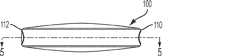
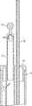
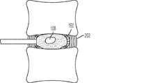
図1〜8を参照すると、最小侵襲性のまたは経皮送達可能な脊椎インプラント100の態様は、充填可能な外側エンクロージャ102および充填可能な内側エンクロージャ104を含む。充填可能な外側エンクロージャ102は外側エンクロージャ106を形成し、充填可能な内側エンクロージャ104は内側チャンバ108を形成する。内側チャンバ108は外側チャンバ102内に封入されている。本明細書の中で使用される「封入されている」とは、内側チャンバ108が、その全側面を外側チャンバ106によって実質的に包囲されるように、内側チャンバ108が外側チャンバ106内に実質的に収容されていることをいう。充填可能な外側および内側エンクロージャ102および104は、シリコーンゴムのようなエラストマー材料のシームレス一体材料片として形成され得る。エラストマー材料の使用は、伸展性の外側および内側エンクロージャ102および104を生じる。すなわち、外側および内側エンクロージャ102および104は、硬化性材料が充填されるとき、内圧が増すとともに膨張する。伸展性のエンクロージャの使用はいくつかの利点を提供する。伸展性のエンクロージャは、髄核腔の不規則な、平らな、または円板状の形状を受け入れる。さらに、伸展性のエンクロージャは、エラストマー硬化ののち髄核インプラントの適切な弾性率を維持し、椎骨セグメントの生体力学的移動性を保つのに役立ち、中央の空隙中への硬化シリコーン成分の妨げられない変形を可能にするのに役立ち得る。充填可能な内側および外側エンクロージャ102および104の物理的特性は、所望の物理的結果を提供するように調整され得る。たとえば、いくつかの態様において、エンクロージャ102、104は横断面中で優先的に膨張する。いくつかの態様において、充填可能な内側および外側エンクロージャ102および104は、完全または部分的に半伸展性または非伸展性であってもよい(すなわち、内圧が増しても膨張しないか、または膨張が僅かである)。いくつかの態様においては、充填可能な内側および外側エンクロージャ102および104の異なる部分が異なる材料で形成されて、エンクロージャ102、104に異なる特性を提供することもできる。Nucleus Implants With reference to FIGS. 1-8, aspects of the minimally invasive or transdermally deliverable
インプラント100は、好ましくは、しぼませた状態で経皮的に、または最小侵襲手術を使用して除核椎間板腔中に挿入されたのち、除核椎間板腔を充填するために充填されることができるようにサイズ設定される。1つの態様において、充填されたインプラント100の外形は、およそ長さ30mm、幅20mm、高さ10mmであり、充填可能な内側エンクロージャ104の外形は、およそ長さ9mm、幅6mm、厚さ6mmである。いくつかの態様において、エンクロージャは、充填されたときに有意に膨張しない(すなわち、非伸展性または半伸展性である)。他の態様において、インプラントは、埋め込まれたとき、約100%膨張する(すなわち、サイズが倍増する)ように充填される。他の態様において、インプラントは、埋め込まれたとき、100%よりも大きく膨張するように充填される。
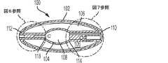
充填可能な外側エンクロージャ102は、第一(または基)端110および第二(または末)端112を有する。充填可能な内側エンクロージャ104は、基端ネック116に結合された第一(または基)端114を有する。充填可能な内側エンクロージャ104の第二(または末)端118は末端ネック120に結合されている。末端ネック部120の端部122は充填可能な外側エンクロージャ102の末端112に結合され、基端ネック116の端部124は充填可能な外側エンクロージャ102の基端110に結合されている。図示される態様において、基端ネック124の端部124は、以下さらに詳細に説明されるように、一体の材料片としていっしょに形成されることにより、充填可能な外側エンクロージャ102の基端110に結合される。充填可能な外側エンクロージャ102の末端112は内側に向けられ、末端ネック部の端部122に結合されて実質的に液密のシールを形成する。このようにエンクロージャどうしを結合すると、実質的に液密な外側チャンバ106が形成する。 The fillable
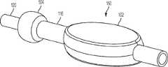
基端ネック116によって形成された開口の中に基端プラグ126が配置される。基端ネック116は、基端プラグ126上の対応する機構と嵌合して基端プラグ126の配置を支援するための、溝148のような機構を有し得る。基端プラグ126は、基端ネック116に挿入され、それと結合され得る。基端プラグ126は、インフレーションスタイラス130のインフレーションチップ192と嵌合するように適合されている。レセプタクル132が、インフレーションチップ192の第一のルーメン186を受けて、材料を開口134に通して外側チャンバ106の中に送る。開口134は、材料を外側チャンバ106に送るときにボトルネックとなり得、開口134のサイズを最大限にするように削られた穴として形成され得る。基端プラグ126は、エンクロージャ102、104と適合性であるシリコーンまたは別の材料で作製され得、射出成形のような従来の製造技術を使用して製造され得る。 The
いくつかの態様においては、基端プラグ126からのインフレーションスタイラス130の偶発的な脱離を防ぐのに役立つためのロック機構が提供される。たとえば、凹み136が基端プラグ126中に提供されてもよく、嵌合する機構(たとえば図13のビーズ152)がインフレーションチップ192上に提供されてもよい。 In some embodiments, a locking mechanism is provided to help prevent accidental detachment of the
アクセスルーメン138が基端プラグ126を通って延び、内側チャンバ108へのアクセスを提供する。図3に見てとれるように、レセプタクル132およびアクセスルーメン138を配置して、インフレーションスタイラス130の不適切な設置を防止することができる。いくつかの態様(図10に示すような)においては、インフレーションスタイラス130の不適切な設置を物理的に防止するためのキー214が提供される。キー214は、インフレーションチップ130の挿入深さを制御するために使用され得る。または、他の態様においては、位置決めカラー190を使用してインフレーションチップ130の挿入深さを制御してもよい。アクセスルーメン138は、内側チャンバ108のための通気口として働くために、埋込み後でも開いたままであるように構成される。 An
末端ネックを封止するために末端ネック120中に末端プラグ140が配置される。末端プラグ140は、インフレーションスタイラス130のコントラストルーメン188の末端200を受けるための円柱形の凹み142を内部側に有し得る。別の円柱形の凹み146が末端プラグ140に提供されてもよい。末端プラグ140は、エンクロージャ102、104とで適合性であるシリコーンまたは別の材料から作製され得、射出成形のような従来の製造技術を使用して製造され得る。 An
織物バンド
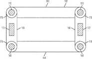
図14〜17を参照すると、インプラント100を補強するために任意の環状補強バンド160が提供され得る。環状補強バンド160は、患者の線維輪が損傷している場合に有用である。1つの態様において、環状補強バンド160は管状の織物材料を含む。環状補強バンド160は、インプラント100の外側輪郭の周囲に配置されて、外側および内側のバルーン102および104の周方向への過度な膨らみを最小化または防止する。周方向膨張を抑制することはまた、バルーン102、104の垂直方向膨張を促進して隣接する椎骨を伸延させ、椎間板腔を広げる。椎骨の上下の終板がインプラント100の垂直方向膨張を制限する。いくつかの態様において、環状補強バンド160は織物で形成されている。1つの態様において、環状補強バンド160は、膨張するときのバンドの短縮を最小化または実質的に防止する軸方向ウィーブ(織り方)を使用する。Percutaneous Implantable Nuclear Implantと題する米国特許第8,636,803号は、環状補強バンド160の他の適当な構造を開示しており、すべての趣旨に関して参照により全体として本明細書に組み入れられる。環状補強バンド160に適した1つの材料が、超高分子量ポリエチレン繊維、たとえばKoninklijke DSM N.V.(Heerleen, the Netherlands)から市販されているDYNEEMA(登録商標)繊維である。Woven Bands With reference to FIGS. 14-17, any annular reinforcing
環状補強バンド160は、上縁162、下縁164、および上縁162と下縁164との間の中央ゾーン166を有する。インプラント100の展開中に環状補強バンドを配置しやすくするために、1つまたは複数のプルストリングおよび調節要素が提供される。1つの態様においては、下プルストリング168、上プルストリング170、および調節要素172が提供される。上プルストリングはポケット176内に配置されるか、または他のやり方で環状補強バンド160の上縁162に結合される。同様に、下プルストリング168は、ポケット176内に配置されるか、または他のやり方で環状補強バンド160の下縁164に結合される。下および上のプルストリングは、環状補強バンド160の縁を内に引っ張り、それによってインプラント100を拘束し、配置することを支援するために、展開中にドローストリングとして使用する(すなわち引っ張る)ことができる。調節要素172は環状バンド160の中央ゾーン166に配置されている。環状バンド160が管状材料を含むならば、調節要素172は管状材料の内側に配置される。他の態様において、調節要素172は、環状補強バンド160上に形成されたポケット内に配置される。調節要素172は、環状補強バンド160の周囲に延びる、ニチノールのフラットリボンのようなワイヤであってもよい。調節要素172を使用して環状補強バンド160を線維輪へと外に押し得る。調節要素172およびプルストリング168、170の動作のさらなる詳細は後述する。 The annular reinforcing
インフレーションスタイラスおよび送出しシース
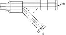
図10〜13を参照すると、インプラント100および環状補強バンド160を送るために、インフレーションスタイラス130を送出しシースとともに使用し得る。インフレーションスタイラス130は、基端182および末端184を有するシャフト180を含む。第一のルーメン186および第二のルーメン188がシャフト180を通って延びる。第一および第二のルーメン186および188を所望の部分に維持するために、位置決めカラー190が提供されている。第一および第二のルーメン186および188の末端が、基端プラグ126と嵌合するように構成されているインフレーションチップ192を形成する。Inflation stylus and delivery sheath With reference to FIGS. 10-13, the
第一の(またはシリコーン)ルーメン186は、インフレーションスタイラス130の基端182からインフレーションスタイラス130の末端184まで延びる。インフレーションスタイラス130が基端プラグ126と嵌合すると、第一のルーメン186の末端の開口194が基端プラグ126の開口134と一致して、外側チャンバ106と第一のルーメン186との間の流体連通を可能にする。ルーメン186の基端は、当業者には公知の一般的なインフレーションツール(たとえばシリンジ)への接続のためのコネクタ196を備えている。 The first (or silicone)
図13に示すような特定の態様においては、シリコーンまたは別の適当な材料が外側チャンバ106に送られるときに、空気がシリコーンルーメン186から出ることを可能にするための通気孔198が提供され得る。通気口198は、硬化性シリコーンのようなより粘性の流体には抵抗しながらも、空気がそれを通って自由に移動することを可能にするのに十分な大きさであり得る。本明細書の中で使用される「シリコーンルーメン」とは、任意の所望の流体を外側チャンバ106に送るためのルーメンを指し、シリコーン以外の材料を包含することができることが理解されるべきである。通気口198は、好ましくは、シャフト180を通って延びて、インフレーションスタイラス130の基端で大気に通じる。 In certain embodiments as shown in FIG. 13, vents 198 may be provided to allow air to exit the
第二の(またはコントラスト)ルーメン188がインフレーションスタイラス130の基端182からインフレーションスタイラス130の末端184まで延びる。コントラストルーメン188は、インフレーションスタイラス130の基端の外に延びる。好ましくは、コントラストルーメン188は、コントラストルーメン188の末端200の位置をインフレーションスタイラス130の末端184に対して伸ばしたり、引き込んだりし得るよう、インフレーションスタイラス130に対して独立して移動可能である。埋込み前の送出しの場合、コントラストルーメン188はアクセスルーメン138を通って伸びることができ、コントラストルーメン188の末端チップが末端プラグ140の凹み142内に配置されてそれを定位置に保持することができる。コントラストルーメン188は、内側チャンバ108から流体を送り、取り出すために使用することができる。いくつかの態様において、コントラストルーメン188の末端200は、内側チャンバ108から流体をより容易に取り出すことを可能にする形状に予備成形されている。1つの特定の態様において、コントラストルーメン188は、内側チャンバ108の底部へのより容易なアクセスを可能にするカーブした形状に予備成形されている。カーブした形状が、コントラストルーメン188を伸ばし、引き込む能力と合わさって、内側チャンバ108から流体を抜き取るために使用されるときそれを調節することを可能にする。本明細書の中で使用される「コントラストルーメン」は、任意の所望の流体を内側チャンバ108に送るためのルーメンをいうものと理解されるべきであり、造影剤以外の材料をも包含することができる。造影剤は、X線透視検査法のような画像診断法の下で可視性を確保するために使用され得る。 A second (or contrast)
図16を参照すると、送出しシース174は、インフレーションスタイラス130のシャフト180に嵌まるようにサイズ設定されたルーメンを含む。インプラント100を送る場合には、インプラント100をインフレーションチップ192上に配置し、組み立てたボディを送出しシース174の末端中に引き込む。プルワイヤ168、170および調節要素172が使用されるならば、それらは、送出しシースのルーメンに通して配置され得る。 Referring to FIG. 16, the
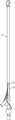
インプラント製造法
図8〜9を参照すると、インプラント100は、充填可能な内側エンクロージャ104に結合された充填可能な外側エンクロージャ102を含むインプラントブランク150を形成することによって形成し得る。インプラントブランク150は、射出成形または浸漬成形のような従来の製造技術を使用して製造し得る。インプラントブランク150を形成したのち、インプラントブランク150をいくらか転回させて、充填可能な内側エンクロージャ104を充填可能な外側エンクロージャ102の内部に配置する。末端プラグ140を末端ネック120に挿入し、基端プラグ126を基端ネック116に挿入する。1つの適当な製造技術に関するさらなる詳細が、参照により全体として本明細書に組み入れられる、2014年11月4日に出願された「Percutaneous Implantable Nuclear Prosthesis」と題する同時係属出願62/074,295に開示されている。Implant Manufacturing Method With reference to FIGS. 8-9, the
インプラント展開法
図18〜23を参照すると、充填可能なインプラント100は、最小侵襲または経皮的手術を使用して展開させるのに特に適している。Implant Deployment Method With reference to Figures 18-23, the
充填可能なインプラント100を埋め込むには、椎間板切除術を実施することにより、線維輪202を実質的に無傷のまま残しながら既存の髄核を除去する。好ましくは、椎間板切除術は、カニューレ208を使用して線維輪202中の小さな開口部を通して椎間板腔206にアクセスする、経皮的技術のような最小侵襲手術を使用して実施される。1つの態様において、椎間板腔は、Kambinの三角形を通す後外側到達法を使用してアクセスされる。前方到達法を使用してもよい。線維輪の完全性を可能な限り保存するために、ガイドピン(たとえばKワイヤ)およびガイドピン上に配置された一連の直径が増大する拡張器を線維輪に貫通させることによって線維輪中にアニュロトミーを形成し得る。所望の直径が得られたならば、アクセスカニューレ208を最大直径の上に配置し、拡張器セットを取り外す。この手順が、線維輪の線維帯を広げて、任意の組織を切除(すなわち除去)することなく(それが治癒過程を支援する)アニュロトミーを形成する。または、線維輪をメスで穿刺して垂直方向のスリットを形成して、髄核腔へのアクセスを得てもよい。 To implant the
カニューレ208が所定の位置に配されたならば、医師は、任意の適当な器具(たとえば骨鉗子)を使用して既存の椎間板を除去し得る。医師は、線維輪の周囲を損傷したり、上下の椎体終板を貫通したりすることを避けるべきである。医師は、伸展性のイメージングバルーンを椎間板腔に挿入し、イメージングバルーンを造影剤で膨らませることによって椎間板切除術の進行をモニタし得る。いくつかの態様において、イメージングバルーンは、膨張可能な外側エンクロージャ102を含むが膨張可能な内側エンクロージャを含まない、変形インプラントを含む。イメージングバルーンはまた、最終的なインプラントの体積、形状および配置を予測するためのトライアルインプラントとしても働く。 Once the cannula 208 is in place, the physician can remove the existing disc using any suitable instrument (eg, bone forceps). Physicians should avoid damaging the perimeter of the annulus fibrosus or penetrating the upper and lower vertebral endplates. Physicians can monitor the progress of discectomy by inserting an extensible imaging balloon into the disc cavity and inflating the imaging balloon with a contrast agent. In some embodiments, the imaging balloon comprises a deformed implant that includes an inflatable
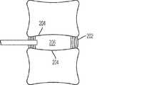
医師が満足するまで既存の髄核が除去されたならば、線維輪202および椎体終板204は実質的に空の除核椎間板腔206を形成する(図18)。 If the existing nucleus pulposus is removed until the physician is satisfied, the
送出しシース174中に装填されたインプラント100は、カニューレ208に通して、除核椎間板腔206内に配置される。一般に、インプラントは椎間板腔の遠端に送られる。そして、送出しシース174を抜き取って、除核椎間板腔内でインプラント100を露出させる。 The
任意の環状補強バンドが提供されるならば、調節部材172を操作して、環状補強バンド160の中央ゾーン166を線維輪202の内面に押し当てて実質的に同一平面にする。プルストリング168、170を引っ張って環状補強バンド160の縁162、164を締め付け、インプラント100を受けるためのポケットを形成し得る。調節部材172およびプルストリング168、170は、X線透視検査法での可視化を支援するための放射線不透過性の機構(たとえば白金またはニチノールコーティング)を含んでもよい。 If any annular reinforcing band is provided, the adjusting
いくつかの態様においては、まず、内側チャンバ108を流体で所望のサイズまで充填する。1つの特定の態様においては、実質的に非圧縮性の流体210、たとえば造影剤を使用する。内側チャンバを膨らませる前に、たとえば真空ロックシリンジを使用して、システムから空気をパージすべきである。流体210は、インフレーションスタイラス130のコントラストルーメン188を使用して送られる。内側チャンバ108の膨張圧は、充填可能な内側エンクロージャ104を所望のサイズまで充填するように選択される。 In some embodiments, the
インフレーションスタイラス130を使用して硬化性材料212を外側チャンバ106に送る。硬化性材料212は、好ましくは、エラストマー材料、たとえば放射線不透過性材料(たとえば硫酸バリウム)を含有するシリコーンゴムである。通気口が含まれているため、膨らませる前に外側チャンバから空気を抜く必要はない。硬化性材料212は、充填可能な内側および外側エンクロージャ102および104の材料と重合して一体部材を形成するように選択し得る。硬化性材料212の弾性率および他の特性は、患者固有のパラメータに基づいて選択することができる。たとえば、より若く、より活動的な患者は、より動きが少ない高齢患者よりも堅い材料を要することがある。外側チャンバ106が所望の圧力まで充填されたならば、硬化性材料212を硬化させる。いくつかの態様において、硬化性材料は、短時間、たとえば10分未満または5分未満で硬化する硬化性シリコーンを含む。より短い硬化時間の使用は、より長い硬化の媒体で起こり得る、硬化性媒体から充填可能なエンクロージャへの溶媒の溶出を防止するのに役立ち得る。そのような溶媒の浸出は、充填可能なエンクロージャの構造完全性に悪影響を及ぼすおそれがある。 The
硬化性材料212を硬化させたのち、コントラストルーメン188を使用して実質的に非圧縮性の流体210を除去する。先に述べたように、コントラストルーメン188を動かし、操作して、望む量の非圧縮性流体210を除去し得る。実質的にすべての流体210を除去することが好ましいが;いくらの流体が残る可能性が高く、すべての流体を除去する必要はない。 After curing the
流体210が除去され、硬化性材料212が十分に硬化したならば、インフレーションスタイラス130をカニューレ208に通して完全に抜き取り、カニューレ208を取り外すことができる。任意の環状補強バンドが使用されているならば、プルストリング168、170、調節部材172もまた、カニューレ208に通して抜き取る。 Once the
したがって、インプラント100は、中空の内側チャンバ108を包囲する硬化材料212の環状リングを含む。内側チャンバ108は、流体が出入りすることを可能にするために開いたままであり、それによってショックアブソーバとして機能する。この構造は、椎間板腔に加えられる垂直および水平の負荷応力を、外向きではなく内向きに(図23の方向矢印を参照)、内側チャンバ108の中心へと向け直すことを可能にする。そのうえ、環状補強バンド160が生来の線維輪202の組織内部成長を促進し、それによって生来の線維輪202に補強を提供する。 Therefore,
上記詳細な説明および例が例示的な態様の構造および使用の完全な説明を提供する。ある程度の具体性をもって、または1つまたは複数の個々の態様を参照しながら特定の態様を先に説明したが、当業者は、本発明の範囲を逸脱することなく、開示された態様に対して数多くの変更を加えることができる。そのようなものとして、本装置の様々な例示的態様は、開示された特定の形態に限定されるものとは解釈されない。むしろ、特許請求の範囲に入るすべての改変および代替を含み、示されたもの以外の態様が、示された態様の特徴のいくつかまたはすべてを含んでもよい。たとえば、構成部品が一体構造として組み合わされてもよいし、接続が置き換えられてもよい(たとえば、ねじがプレス嵌めまたは溶接に置き換えられてもよい)。さらに、適切ならば、上記例のいずれかの局面を、記載された他の例のいずれかの局面と組み合わせて、匹敵しうる、または異なる性質を有し、かつ同じまたは異なる問題に対応するさらなる例を形成してもよい。同様に、上記恩典および利点は、1つの態様に関してもよいし、いくつかの態様に関してもよいことが理解されよう。 The detailed description and examples provided above provide a complete description of the structure and use of exemplary embodiments. Although specific embodiments have been described above with some specificity or with reference to one or more individual embodiments, those skilled in the art will appreciate the disclosed embodiments without departing from the scope of the invention. Many changes can be made. As such, the various exemplary embodiments of the device are not construed as being limited to the particular embodiments disclosed. Rather, it may include all modifications and alternatives that fall within the claims, and aspects other than those shown may include some or all of the features of the indicated aspects. For example, the components may be combined as an integral structure or the connections may be replaced (eg, the screws may be replaced by press fitting or welding). Further, where appropriate, any aspect of the above example may be combined with any aspect of the other examples described to address comparable or different properties and address the same or different problems. An example may be formed. Similarly, it will be appreciated that the above benefits and benefits may be in one aspect or in several aspects.
特許請求の範囲は、所与の請求項の中でそれぞれ「〜のための手段」または「〜する工程」を使用して明示的に述べられない限り、ミーンズプラスファンクションまたはステッププラスファンクションの限定を含むことを意図せず、そのように解釈されるべきではない。 The scope of claims is a limitation of means plus function or step plus function unless explicitly stated in a given claim using "means for" or "step to", respectively. It is not intended to be included and should not be construed as such.
Claims (19)
Translated fromJapanese基端および末端を有する、充填可能な外側エンクロージャであって、
該充填可能な内側および外側エンクロージャの該基端どうしが結合され、かつ該充填可能な内側および外側エンクロージャの該末端どうしが結合されて、該充填可能な内側エンクロージャを封入するようになっている、充填可能な外側エンクロージャ;
該充填可能な内側エンクロージャの該末端の該末端開口部を封止するための、末端プラグ;および
該充填可能な内側エンクロージャの該基端の該基端開口部を封止するための、基端プラグであって、
該充填可能な内側エンクロージャへのアクセスを提供するためのアクセスルーメンと、該充填可能な外側エンクロージャへのアクセスを提供するため開口部を有するレセプタクルとを有し、
該充填可能な内側エンクロージャへのアクセスを提供するための該アクセスルーメンが埋込み後でも開いたままであるように構成されている、基端プラグ
を含む、脊椎インプラント装置、ならびに
該基端プラグと嵌合するように適合されたインフレーションスタイラスであって、
該アクセスルーメンを通って移動可能に延びて該充填可能な内側エンクロージャから流体を送りかつ取り出すための、調節可能な第一のルーメン;および
流体を該充填可能な外側エンクロージャに送るための、第二のルーメン
を含む、インフレーションスタイラス
を含む、髄核代替装置を埋め込むためのキット。Fillable inner enclosure with base end with base end opening and end with end end opening;
Fillable outer enclosure with base and end
The base ends of the fillable inner and outer enclosures are joined together, and the ends of the fillable inner and outer enclosures are joined together to enclose the fillable inner enclosure. Fillable outer enclosure;
A terminal plug for sealing the terminal opening at the end of the fillable inner enclosure; and a proximal end for sealing the proximal opening at the proximal end of the fillable inner enclosure. It ’s a plug,
It has an access lumen to provide access to the fillable inner enclosure and a receptacle with an opening to provide access to the fillable outer enclosure.
A spinal implant device, including a proximal plug, and mating with the proximal plug, the access lumen for providing access to the fillable inner enclosure is configured to remain open after implantation. Inflation stylus adapted to
An adjustable first lumen for movably extending through the access lumen tofeed and remove fluid from the fillable inner enclosure; and a second for feeding fluid to thefillable outer enclosure. A kit for implanting a nucleus pulposus replacement device, including an inflation stylus, including lumens.
基端および末端を有する、充填可能な外側エンクロージャであって、
該充填可能な内側および外側エンクロージャの該基端どうしが結合され、かつ該充填可能な内側および外側エンクロージャの該末端どうしが結合されて、該充填可能な内側エンクロージャを実質的に封入するようになっている、充填可能な外側エンクロージャ;
該充填可能な内側エンクロージャの該末端の該末端開口部を封止するための、末端プラグ;および
該充填可能な内側エンクロージャの該基端中の該基端開口部を封止するための、基端プラグであって、
該充填可能な内側エンクロージャへのアクセスを提供するためのアクセスルーメンと、該充填可能な外側エンクロージャへのアクセスを提供するため開口を有するレセプタクルとを有し、
該充填可能な内側エンクロージャへのアクセスを提供するための該アクセスルーメンが埋込み後でも開いたままであるように構成されている、基端プラグ
を含む、脊椎インプラント装置であって、
該基端プラグは、該基端開口部に結合し、かつ該基端プラグの該末端を通って該基端プラグの該基端から実質的に長手方向に伸びる少なくとも1つのルーメンを含むインフレーションスタイラスを受けるように適合されている、
該脊椎インプラント装置。Fillable inner enclosure with base end with base end opening and end with end end opening;
Fillable outer enclosure with base and end
The base ends of the fillable inner and outer enclosures are joined together, and the ends of the fillable inner and outer enclosures are joined together to substantially enclose the fillable inner enclosure. Fillable outer enclosure;
A terminal plug for sealing the terminal opening at the end of the fillable inner enclosure; and a base for sealing the proximal opening in the proximal end of the fillable inner enclosure. It ’s an end plug,
It has an access lumen to provide access to the fillable inner enclosure and a receptacle with an opening to provide access to the fillable outer enclosure.
A spinal implant device, including a proximal plug, configured such that the access lumen to provide access to the fillable inner enclosure remains open after implantation.
The proximal plug is an inflation stylus that is coupled to the proximal opening and contains at least one lumen that extends substantially longitudinally from the proximal end of the proximal plug through the distal end of the proximal plug. Adapted to receive,
The spinal implant device .
Applications Claiming Priority (3)
| Application Number | Priority Date | Filing Date | Title |
|---|---|---|---|
| US201562212950P | 2015-09-01 | 2015-09-01 | |
| US62/212,950 | 2015-09-01 | ||
| PCT/US2016/049816WO2017040734A1 (en) | 2015-09-01 | 2016-09-01 | Implantable nuclear prosthesis |
Publications (3)
| Publication Number | Publication Date |
|---|---|
| JP2018527145A JP2018527145A (en) | 2018-09-20 |
| JP2018527145A5 JP2018527145A5 (en) | 2019-10-10 |
| JP6891176B2true JP6891176B2 (en) | 2021-06-18 |
Family
ID=58097257
Family Applications (1)
| Application Number | Title | Priority Date | Filing Date |
|---|---|---|---|
| JP2018530671AActiveJP6891176B2 (en) | 2015-09-01 | 2016-09-01 | Implantable nucleus pulposus prosthesis |
Country Status (10)
| Country | Link |
|---|---|
| US (3) | US10575967B2 (en) |
| EP (1) | EP3344156B1 (en) |
| JP (1) | JP6891176B2 (en) |
| KR (1) | KR102607758B1 (en) |
| CN (1) | CN108348227B (en) |
| AU (1) | AU2016315964B2 (en) |
| CA (1) | CA2997117A1 (en) |
| ES (1) | ES2774513T3 (en) |
| PL (1) | PL3344156T3 (en) |
| WO (1) | WO2017040734A1 (en) |
Families Citing this family (11)
| Publication number | Priority date | Publication date | Assignee | Title |
|---|---|---|---|---|
| US20140277467A1 (en) | 2013-03-14 | 2014-09-18 | Spinal Stabilization Technologies, Llc | Prosthetic Spinal Disk Nucleus |
| KR102464886B1 (en) | 2014-11-04 | 2022-11-08 | 스파이널 스태빌라이제이션 테크놀로지스, 엘엘씨 | Percutaneous implantable nuclear prosthesis |
| WO2016073587A1 (en) | 2014-11-04 | 2016-05-12 | Spinal Stabilization Technologies Llc | Percutaneous implantable nuclear prosthesis |
| JP6891176B2 (en) | 2015-09-01 | 2021-06-18 | スパイナル スタビライゼーション テクノロジーズ リミテッド ライアビリティ カンパニー | Implantable nucleus pulposus prosthesis |
| US10285825B2 (en)* | 2016-04-07 | 2019-05-14 | Howmedica Osteonics Corp. | Surgical insertion instruments |
| EP3456297B1 (en) | 2017-09-15 | 2023-10-04 | Howmedica Osteonics Corp. | Instruments for expandable interbody implants |
| CA3111639A1 (en)* | 2018-09-04 | 2020-05-28 | Spinal Stabilization Technologies, Llc | Implantable nuclear prosthesis, kits, and related methods |
| US11129727B2 (en) | 2019-03-29 | 2021-09-28 | Medos International Sari | Inflatable non-distracting intervertebral implants and related methods |
| US11376131B2 (en)* | 2020-04-07 | 2022-07-05 | Ethicon, Inc. | Cortical rim-supporting interbody device and method |
| CN112535556B (en)* | 2020-11-02 | 2022-04-08 | 淮阴工学院 | Air bag type artificial cervical intervertebral disc prosthesis |
| CN113855230B (en)* | 2021-09-26 | 2023-07-28 | 武汉大学中南医院 | Human tissue cavity modeling device and method |
Family Cites Families (255)
| Publication number | Priority date | Publication date | Assignee | Title |
|---|---|---|---|---|
| CA962021A (en) | 1970-05-21 | 1975-02-04 | Robert W. Gore | Porous products and process therefor |
| US3875595A (en) | 1974-04-15 | 1975-04-08 | Edward C Froning | Intervertebral disc prosthesis and instruments for locating same |
| US4478898A (en) | 1982-06-04 | 1984-10-23 | Junkosha Co., Ltd. | Laminated porous polytetrafluoroethylene tube and its process of manufacture |
| US4517979A (en)* | 1983-07-14 | 1985-05-21 | Cordis Corporation | Detachable balloon catheter |
| US4619641A (en) | 1984-11-13 | 1986-10-28 | Mount Sinai School Of Medicine Of The City University Of New York | Coaxial double lumen anteriovenous grafts |
| US4743480A (en) | 1986-11-13 | 1988-05-10 | W. L. Gore & Associates, Inc. | Apparatus and method for extruding and expanding polytetrafluoroethylene tubing and the products produced thereby |
| US5152782A (en) | 1989-05-26 | 1992-10-06 | Impra, Inc. | Non-porous coated ptfe graft |
| JP2514087Y2 (en) | 1990-05-25 | 1996-10-16 | 幸三 牧田 | Balloon with detachable double-sided check valve |
| US5192326A (en) | 1990-12-21 | 1993-03-09 | Pfizer Hospital Products Group, Inc. | Hydrogel bead intervertebral disc nucleus |
| US5123926A (en) | 1991-02-22 | 1992-06-23 | Madhavan Pisharodi | Artificial spinal prosthesis |
| US5192310A (en) | 1991-09-16 | 1993-03-09 | Atrium Medical Corporation | Self-sealing implantable vascular graft |
| US5282827A (en) | 1991-11-08 | 1994-02-01 | Kensey Nash Corporation | Hemostatic puncture closure system and method of use |
| US5439467A (en) | 1991-12-03 | 1995-08-08 | Vesica Medical, Inc. | Suture passer |
| US5466509A (en) | 1993-01-15 | 1995-11-14 | Impra, Inc. | Textured, porous, expanded PTFE |
| US5439464A (en) | 1993-03-09 | 1995-08-08 | Shapiro Partners Limited | Method and instruments for performing arthroscopic spinal surgery |
| FR2706309B1 (en) | 1993-06-17 | 1995-10-06 | Sofamor | Instrument for surgical treatment of an intervertebral disc by the anterior route. |
| FR2709947B1 (en) | 1993-09-13 | 1995-11-10 | Bard Sa Laboratoires | Curved prosthetic mesh and its manufacturing process. |
| US20060100635A1 (en)* | 1994-01-26 | 2006-05-11 | Kyphon, Inc. | Inflatable device for use in surgical protocol relating to fixation of bone |
| US6716216B1 (en) | 1998-08-14 | 2004-04-06 | Kyphon Inc. | Systems and methods for treating vertebral bodies |
| US5437661A (en) | 1994-03-23 | 1995-08-01 | Rieser; Bernhard | Method for removal of prolapsed nucleus pulposus material on an intervertebral disc using a laser |
| US5888220A (en) | 1994-05-06 | 1999-03-30 | Advanced Bio Surfaces, Inc. | Articulating joint repair |
| US6248131B1 (en) | 1994-05-06 | 2001-06-19 | Advanced Bio Surfaces, Inc. | Articulating joint repair |
| US6140452A (en) | 1994-05-06 | 2000-10-31 | Advanced Bio Surfaces, Inc. | Biomaterial for in situ tissue repair |
| US5571189A (en) | 1994-05-20 | 1996-11-05 | Kuslich; Stephen D. | Expandable fabric implant for stabilizing the spinal motion segment |
| JPH10511012A (en) | 1994-09-23 | 1998-10-27 | インプラ・インコーポレーテッド | Carbon-containing vascular graft and method for producing the same |
| JPH08196538A (en) | 1994-09-26 | 1996-08-06 | Ethicon Inc | Tissue sticking apparatus for surgery with elastomer component and method of attaching mesh for surgery to said tissue |
| JPH10507386A (en) | 1994-10-17 | 1998-07-21 | レイメディカ, インコーポレイテッド | Artificial spinal disc nucleus |
| US5674296A (en) | 1994-11-14 | 1997-10-07 | Spinal Dynamics Corporation | Human spinal disc prosthesis |
| US5879366A (en) | 1996-12-20 | 1999-03-09 | W.L. Gore & Associates, Inc. | Self-expanding defect closure device and method of making and using |
| US6896696B2 (en) | 1998-11-20 | 2005-05-24 | Scimed Life Systems, Inc. | Flexible and expandable stent |
| EP0828524A2 (en) | 1995-05-05 | 1998-03-18 | Advanced Cardiovascular Systems, Inc. | Intraluminal device with lubricious surface |
| US5628786A (en) | 1995-05-12 | 1997-05-13 | Impra, Inc. | Radially expandable vascular graft with resistance to longitudinal compression and method of making same |
| GB9510624D0 (en) | 1995-05-25 | 1995-07-19 | Ellis Dev Ltd | Textile surgical implants |
| US5702449A (en) | 1995-06-07 | 1997-12-30 | Danek Medical, Inc. | Reinforced porous spinal implants |
| US5890268A (en) | 1995-09-07 | 1999-04-06 | Case Western Reserve University | Method of forming closed cell metal composites |
| US6007570A (en) | 1996-08-13 | 1999-12-28 | Oratec Interventions, Inc. | Apparatus with functional element for performing function upon intervertebral discs |
| US6042605A (en) | 1995-12-14 | 2000-03-28 | Gore Enterprose Holdings, Inc. | Kink resistant stent-graft |
| US5645597A (en) | 1995-12-29 | 1997-07-08 | Krapiva; Pavel I. | Disc replacement method and apparatus |
| US5800512A (en) | 1996-01-22 | 1998-09-01 | Meadox Medicals, Inc. | PTFE vascular graft |
| US5865845A (en) | 1996-03-05 | 1999-02-02 | Thalgott; John S. | Prosthetic intervertebral disc |
| JP3273735B2 (en) | 1996-05-17 | 2002-04-15 | 日東電工株式会社 | Polytetrafluoroethylene porous membrane and method for producing the same, sheet-like polytetrafluoroethylene molded article, and filter medium for air filter |
| US6126682A (en) | 1996-08-13 | 2000-10-03 | Oratec Interventions, Inc. | Method for treating annular fissures in intervertebral discs |
| US5954764A (en) | 1996-09-20 | 1999-09-21 | Parodi; Juan Carlos | Device for concurrently placing an endovascular expander with an endovascular prosthesis |
| US6019793A (en) | 1996-10-21 | 2000-02-01 | Synthes | Surgical prosthetic device |
| EP0873145A2 (en) | 1996-11-15 | 1998-10-28 | Advanced Bio Surfaces, Inc. | Biomaterial system for in situ tissue repair |
| FR2755846B1 (en) | 1996-11-20 | 1998-12-31 | Jacques Philippe Laboureau | PRE-ORIENT PROSTHETIC LIGAMENT AND METHOD OF MAKING |
| US20080086212A1 (en) | 1997-01-02 | 2008-04-10 | St. Francis Medical Technologies, Inc. | Spine distraction implant |
| US7201751B2 (en) | 1997-01-02 | 2007-04-10 | St. Francis Medical Technologies, Inc. | Supplemental spine fixation device |
| EP1905392B1 (en) | 1997-03-07 | 2011-05-18 | Kyphon SÀRL | System for percutaneous bone and spinal stabilization, fixation and repair |
| US5981826A (en) | 1997-05-05 | 1999-11-09 | Georgia Tech Research Corporation | Poly(vinyl alcohol) cryogel |
| US6007575A (en) | 1997-06-06 | 1999-12-28 | Samuels; Shaun Laurence Wilkie | Inflatable intraluminal stent and method for affixing same within the human body |
| US5972015A (en) | 1997-08-15 | 1999-10-26 | Kyphon Inc. | Expandable, asymetric structures for deployment in interior body regions |
| US6852095B1 (en) | 1997-07-09 | 2005-02-08 | Charles D. Ray | Interbody device and method for treatment of osteoporotic vertebral collapse |
| US6175758B1 (en) | 1997-07-15 | 2001-01-16 | Parviz Kambin | Method for percutaneous arthroscopic disc removal, bone biopsy and fixation of the vertebrae |
| FR2767671B1 (en) | 1997-08-27 | 1999-11-26 | Ethnor | PROSTHETIC SHUTTER DEVICE FOR SHUTTERING HERNARY CHANNELS |
| US5888226A (en) | 1997-11-12 | 1999-03-30 | Rogozinski; Chaim | Intervertebral prosthetic disc |
| US5976174A (en) | 1997-12-15 | 1999-11-02 | Ruiz; Carlos E. | Medical hole closure device and methods of use |
| US6079868A (en) | 1997-12-18 | 2000-06-27 | Advanced Bio Surfaces, Inc. | Static mixer |
| US6482217B1 (en) | 1998-04-10 | 2002-11-19 | Endicor Medical, Inc. | Neuro thrombectomy catheter |
| US6224630B1 (en) | 1998-05-29 | 2001-05-01 | Advanced Bio Surfaces, Inc. | Implantable tissue repair device |
| US5928284A (en) | 1998-07-09 | 1999-07-27 | Mehdizadeh; Hamid M. | Disc replacement prosthesis |
| FR2787014B1 (en) | 1998-12-11 | 2001-03-02 | Dimso Sa | INTERVERTEBRAL DISC PROSTHESIS WITH REDUCED FRICTION |
| FR2787016B1 (en) | 1998-12-11 | 2001-03-02 | Dimso Sa | INTERVERTEBRAL DISK PROSTHESIS |
| FR2787018B1 (en) | 1998-12-11 | 2001-03-02 | Dimso Sa | INTERVERTEBRAL DISC PROSTHESIS WITH LIQUID ENCLOSURE |
| FR2787017B1 (en) | 1998-12-11 | 2001-04-27 | Dimso Sa | INTERVERTEBRAL DISC PROSTHESIS WITH IMPROVED MECHANICAL BEHAVIOR |
| ES2259996T3 (en) | 1999-01-22 | 2006-11-01 | Gore Enterprise Holdings, Inc. | ENDOPROTESIS COVER. |
| US7018401B1 (en) | 1999-02-01 | 2006-03-28 | Board Of Regents, The University Of Texas System | Woven intravascular devices and methods for making the same and apparatus for delivery of the same |
| US6398803B1 (en) | 1999-02-02 | 2002-06-04 | Impra, Inc., A Subsidiary Of C.R. Bard, Inc. | Partial encapsulation of stents |
| US6436143B1 (en) | 1999-02-22 | 2002-08-20 | Anthony C. Ross | Method and apparatus for treating intervertebral disks |
| US6206921B1 (en) | 1999-02-22 | 2001-03-27 | Peter A. Guagliano | Method of replacing nucleus pulposus and repairing the intervertebral disk |
| US6183518B1 (en) | 1999-02-22 | 2001-02-06 | Anthony C. Ross | Method of replacing nucleus pulposus and repairing the intervertebral disk |
| US6428576B1 (en) | 1999-04-16 | 2002-08-06 | Endospine, Ltd. | System for repairing inter-vertebral discs |
| US6805697B1 (en) | 1999-05-07 | 2004-10-19 | University Of Virginia Patent Foundation | Method and system for fusing a spinal region |
| US6283998B1 (en) | 1999-05-13 | 2001-09-04 | Board Of Trustees Of The University Of Arkansas | Alloplastic vertebral disk replacement |
| US6673103B1 (en) | 1999-05-20 | 2004-01-06 | Scimed Life Systems, Inc. | Mesh and stent for increased flexibility |
| US7273497B2 (en) | 1999-05-28 | 2007-09-25 | Anova Corp. | Methods for treating a defect in the annulus fibrosis |
| US6419704B1 (en) | 1999-10-08 | 2002-07-16 | Bret Ferree | Artificial intervertebral disc replacement methods and apparatus |
| US6969404B2 (en) | 1999-10-08 | 2005-11-29 | Ferree Bret A | Annulus fibrosis augmentation methods and apparatus |
| US20060247665A1 (en) | 1999-05-28 | 2006-11-02 | Ferree Bret A | Methods and apparatus for treating disc herniation and preventing the extrusion of interbody bone graft |
| US6780497B1 (en) | 1999-08-05 | 2004-08-24 | Gore Enterprise Holdings, Inc. | Surface modified expanded polytetrafluoroethylene devices and methods of producing the same |
| US7201776B2 (en) | 1999-10-08 | 2007-04-10 | Ferree Bret A | Artificial intervertebral disc replacements with endplates |
| CA2425951C (en) | 1999-08-18 | 2008-09-16 | Intrinsic Therapeutics, Inc. | Devices and method for nucleus pulposus augmentation and retention |
| US7717961B2 (en) | 1999-08-18 | 2010-05-18 | Intrinsic Therapeutics, Inc. | Apparatus delivery in an intervertebral disc |
| US20120316648A1 (en) | 1999-08-18 | 2012-12-13 | Intrinsic Therapeutics, Inc. | Intervertebral disc reinforcement systems |
| US6264695B1 (en) | 1999-09-30 | 2001-07-24 | Replication Medical, Inc. | Spinal nucleus implant |
| US20030153976A1 (en) | 1999-10-20 | 2003-08-14 | Cauthen Joseph C. | Spinal disc annulus reconstruction method and spinal disc annulus stent |
| US7717958B2 (en) | 2000-02-16 | 2010-05-18 | Trans1, Inc. | Prosthetic nucleus apparatus |
| US6740093B2 (en) | 2000-02-28 | 2004-05-25 | Stephen Hochschuler | Method and apparatus for treating a vertebral body |
| US6332894B1 (en) | 2000-03-07 | 2001-12-25 | Zimmer, Inc. | Polymer filled spinal fusion cage |
| US6402750B1 (en) | 2000-04-04 | 2002-06-11 | Spinlabs, Llc | Devices and methods for the treatment of spinal disorders |
| US6689125B1 (en) | 2000-04-04 | 2004-02-10 | Spinalabs, Llc | Devices and methods for the treatment of spinal disorders |
| CN101543422B (en)* | 2000-04-07 | 2012-07-04 | 科丰有限公司 | System for determining the expansion direction of an expandable structure within a bone |
| US6482234B1 (en) | 2000-04-26 | 2002-11-19 | Pearl Technology Holdings, Llc | Prosthetic spinal disc |
| US7008427B2 (en) | 2000-05-25 | 2006-03-07 | Orthoplex, Llc | Inter-vertebral disc prosthesis for rachis through anterior surgery thereof |
| US6875212B2 (en) | 2000-06-23 | 2005-04-05 | Vertelink Corporation | Curable media for implantable medical device |
| US6749614B2 (en) | 2000-06-23 | 2004-06-15 | Vertelink Corporation | Formable orthopedic fixation system with cross linking |
| CA2549320A1 (en) | 2000-08-30 | 2002-03-07 | Sdgi Holdings, Inc. | Intervertebral disc nucleus implants and methods |
| US20020026244A1 (en) | 2000-08-30 | 2002-02-28 | Trieu Hai H. | Intervertebral disc nucleus implants and methods |
| US7204851B2 (en) | 2000-08-30 | 2007-04-17 | Sdgi Holdings, Inc. | Method and apparatus for delivering an intervertebral disc implant |
| US6620196B1 (en) | 2000-08-30 | 2003-09-16 | Sdgi Holdings, Inc. | Intervertebral disc nucleus implants and methods |
| EP1328220B1 (en) | 2000-10-24 | 2011-01-05 | CryoLife, Inc. | Bioprosthetic filler and methods, particularly for the in situ formation of vertebral disc bioprosthetics |
| CA2429149C (en) | 2000-12-15 | 2010-08-24 | Spineology, Inc. | Annulus-reinforcing band |
| US7244272B2 (en) | 2000-12-19 | 2007-07-17 | Nicast Ltd. | Vascular prosthesis and method for production thereof |
| US6936070B1 (en) | 2001-01-17 | 2005-08-30 | Nabil L. Muhanna | Intervertebral disc prosthesis and methods of implantation |
| US20020147496A1 (en) | 2001-04-06 | 2002-10-10 | Integrated Vascular Systems, Inc. | Apparatus for treating spinal discs |
| US6632235B2 (en)* | 2001-04-19 | 2003-10-14 | Synthes (U.S.A.) | Inflatable device and method for reducing fractures in bone and in treating the spine |
| US7156877B2 (en)* | 2001-06-29 | 2007-01-02 | The Regents Of The University Of California | Biodegradable/bioactive nucleus pulposus implant and method for treating degenerated intervertebral discs |
| US20030028251A1 (en) | 2001-07-30 | 2003-02-06 | Mathews Hallett H. | Methods and devices for interbody spinal stabilization |
| US6375682B1 (en) | 2001-08-06 | 2002-04-23 | Lewis W. Fleischmann | Collapsible, rotatable and expandable spinal hydraulic prosthetic device |
| DE50114038D1 (en) | 2001-08-24 | 2008-07-31 | Zimmer Gmbh | Artificial disc |
| CA2457189C (en) | 2001-09-28 | 2011-08-09 | Boston Scientific Limited | Medical devices comprising nanomaterials and therapeutic methods utilizing the same |
| US7267687B2 (en) | 2001-10-02 | 2007-09-11 | Rex Medical, L.P | Spinal implant and method of use |
| JP3580790B2 (en) | 2001-10-31 | 2004-10-27 | 宇明泰化工股▲ふん▼有限公司 | Asymmetric porous polytetrafluoroethylene membrane and method for producing the same |
| GB2382028B (en) | 2001-11-19 | 2006-11-01 | Aberdeen Orthopaedic Developme | Intervertebral disc prosthesis |
| ES2276747T3 (en)* | 2001-12-05 | 2007-07-01 | Synthes Gmbh | INTERVERTEBRAL DISK PROTECTION OR NUCLEUS REPLACEMENT PROTESIS. |
| US6752826B2 (en) | 2001-12-14 | 2004-06-22 | Thoratec Corporation | Layered stent-graft and methods of making the same |
| US6898545B2 (en) | 2002-06-28 | 2005-05-24 | Agilent Technologies Inc | Semiconductor test data analysis system |
| US7993351B2 (en) | 2002-07-24 | 2011-08-09 | Pressure Products Medical Supplies, Inc. | Telescopic introducer with a compound curvature for inducing alignment and method of using the same |
| CA2495404C (en) | 2002-08-15 | 2011-05-03 | Justin K. Coppes | Intervertebral disc implant |
| US7309359B2 (en) | 2003-08-21 | 2007-12-18 | Warsaw Orthopedic, Inc. | Allogenic/xenogenic implants and methods for augmenting or repairing intervertebral discs |
| US6932843B2 (en) | 2002-09-25 | 2005-08-23 | Medicinelodge, Inc. | Apparatus and method for the in-situ formation of a structural prosthesis |
| CA2735324A1 (en) | 2002-11-05 | 2004-05-21 | Spineology, Inc. | A semi-biological intervertebral disc replacement system |
| US6733533B1 (en) | 2002-11-19 | 2004-05-11 | Zimmer Technology, Inc. | Artificial spinal disc |
| US20040186471A1 (en) | 2002-12-07 | 2004-09-23 | Sdgi Holdings, Inc. | Method and apparatus for intervertebral disc expansion |
| US7004971B2 (en) | 2002-12-31 | 2006-02-28 | Depuy Acromed, Inc. | Annular nucleus pulposus replacement |
| AU2004212942A1 (en) | 2003-02-14 | 2004-09-02 | Depuy Spine, Inc. | In-situ formed intervertebral fusion device |
| US6893465B2 (en) | 2003-03-31 | 2005-05-17 | Shi, Tain-Yew | Vividly simulated prosthetic intervertebral disc |
| CN100484499C (en) | 2003-04-14 | 2009-05-06 | 斯恩蒂斯有限公司 | Intervertebral implant |
| US6969405B2 (en) | 2003-04-23 | 2005-11-29 | Loubert Suddaby | Inflatable intervertebral disc replacement prosthesis |
| US20040220672A1 (en) | 2003-05-03 | 2004-11-04 | Shadduck John H. | Orthopedic implants, methods of use and methods of fabrication |
| CA2526507A1 (en) | 2003-05-30 | 2004-12-16 | George P. Teitelbaum | Methods and devices for transpedicular discectomy |
| US6984246B2 (en) | 2003-06-06 | 2006-01-10 | Tain-Yew Shi | Artificial intervertebral disc flexibly oriented by spring-reinforced bellows |
| US7632291B2 (en) | 2003-06-13 | 2009-12-15 | Trivascular2, Inc. | Inflatable implant |
| US20050015150A1 (en) | 2003-07-17 | 2005-01-20 | Lee Casey K. | Intervertebral disk and nucleus prosthesis |
| US6958077B2 (en) | 2003-07-29 | 2005-10-25 | Loubert Suddaby | Inflatable nuclear prosthesis |
| US7153325B2 (en) | 2003-08-01 | 2006-12-26 | Ultra-Kinetics, Inc. | Prosthetic intervertebral disc and methods for using the same |
| US20050055099A1 (en) | 2003-09-09 | 2005-03-10 | Ku David N. | Flexible spinal disc |
| US7632294B2 (en) | 2003-09-29 | 2009-12-15 | Promethean Surgical Devices, Llc | Devices and methods for spine repair |
| US7133001B2 (en) | 2003-11-03 | 2006-11-07 | Toyon Research Corporation | Inflatable-collapsible transreflector antenna |
| US20050119752A1 (en) | 2003-11-19 | 2005-06-02 | Synecor Llc | Artificial intervertebral disc |
| US8012210B2 (en) | 2004-01-16 | 2011-09-06 | Warsaw Orthopedic, Inc. | Implant frames for use with settable materials and related methods of use |
| US8945223B2 (en) | 2004-03-12 | 2015-02-03 | Warsaw Orthopedic, Inc. | In-situ formable nucleus pulposus implant with water absorption and swelling capability |
| WO2005102433A2 (en) | 2004-04-23 | 2005-11-03 | Leonard Edward Forrest | Device for treatment or evacuation of intervertebral disc |
| US7722612B2 (en) | 2004-05-19 | 2010-05-25 | Sintea Biotech S.P.A. | Devices, kit and method for kyphoplasty |
| US8142462B2 (en) | 2004-05-28 | 2012-03-27 | Cavitech, Llc | Instruments and methods for reducing and stabilizing bone fractures |
| US7297158B2 (en) | 2004-06-14 | 2007-11-20 | Thoratec Corporation | Multilayer composite vascular access graft |
| US7789913B2 (en) | 2004-06-29 | 2010-09-07 | Spine Wave, Inc. | Methods for injecting a curable biomaterial into an intervertebral space |
| US7972351B2 (en) | 2004-07-13 | 2011-07-05 | Boston Scientific Scimed, Inc. | Balloon folding design and method and apparatus for making balloons |
| US20060014938A1 (en)* | 2004-07-14 | 2006-01-19 | Groman Ernest V | Stable aqueous colloidal lanthanide oxides |
| WO2006010769A1 (en)* | 2004-07-27 | 2006-02-02 | Hewlett-Packard Development Company, L.P. | Document creation system and related methods |
| WO2006015001A1 (en)* | 2004-07-27 | 2006-02-09 | Synthes (U.S.A.) | Supplementation or replacement of a nucleus pulposus, of an intervertebral disc |
| US20060047296A1 (en) | 2004-08-31 | 2006-03-02 | Sdg Holdings, Inc. | Annulus replacement system and technique |
| WO2006039409A1 (en) | 2004-09-30 | 2006-04-13 | Synecor, Llc | Artificial intervertebral disc nucleus |
| US8317864B2 (en) | 2004-10-20 | 2012-11-27 | The Board Of Trustees Of The Leland Stanford Junior University | Systems and methods for posterior dynamic stabilization of the spine |
| WO2006060482A2 (en) | 2004-12-01 | 2006-06-08 | The Regents Of The University Of California | Systems, devices and methods of treatment of intervertebral disorders |
| US20060265077A1 (en)* | 2005-02-23 | 2006-11-23 | Zwirkoski Paul A | Spinal repair |
| CA2598742A1 (en) | 2005-03-01 | 2006-09-08 | Columna Pty Ltd | Intervertebral disc restoration |
| US7182783B2 (en) | 2005-04-25 | 2007-02-27 | Sdgi Holdings, Inc. | Selectively expandable composite structures for spinal arthroplasty |
| US20060247780A1 (en) | 2005-04-27 | 2006-11-02 | Bert Jeffrey K | Expandable artificial disc and associated methods and instrumentation |
| US8795364B2 (en) | 2005-05-06 | 2014-08-05 | Kensey Nash Corporation | System and devices for the repair of a vertebral disc defect |
| WO2006130796A2 (en) | 2005-06-02 | 2006-12-07 | Zimmer Spine, Inc. | Interbody fusion ring and method of using the same |
| US20070162135A1 (en) | 2005-06-15 | 2007-07-12 | Jerome Segal | Mechanical apparatus and method for artificial disc replacement |
| JP2009501027A (en) | 2005-06-17 | 2009-01-15 | シー・アール・バード・インコーポレイテツド | Vascular graft with kinking resistance after tightening |
| AU2006281991A1 (en) | 2005-08-15 | 2007-02-22 | Spinecell Pty Ltd | A tissue prosthesis and a method of, and equipment for, forming a tissue prosthesis |
| NZ566184A (en) | 2005-08-26 | 2010-07-30 | Synthes Gmbh | Hydrogel balloon prosthesis for nucleus pulposus |
| KR100550585B1 (en) | 2005-08-29 | 2006-02-10 | (주)태연메디칼 | Disposable spinal restoration surgery |
| US7731753B2 (en) | 2005-09-01 | 2010-06-08 | Spinal Kinetics, Inc. | Prosthetic intervertebral discs |
| US8197505B2 (en)* | 2005-10-14 | 2012-06-12 | Endocross Ltd. | Balloon catheter system for treating vascular occlusions |
| US20070093906A1 (en) | 2005-10-26 | 2007-04-26 | Zimmer Spine, Inc. | Nucleus implant and method |
| US20070173935A1 (en) | 2005-10-28 | 2007-07-26 | O'neil Michael J | Nucleus pulposus augmentation pretreatment technique |
| WO2007057908A2 (en) | 2005-11-21 | 2007-05-24 | Nicast Ltd. | Spinal nucleus prosthesis device |
| US20070135921A1 (en) | 2005-12-09 | 2007-06-14 | Park Kee B | Surgical implant |
| US7699894B2 (en) | 2005-12-22 | 2010-04-20 | Depuy Spine, Inc. | Nucleus pulposus trial device and technique |
| US8801790B2 (en) | 2005-12-27 | 2014-08-12 | Warsaw Orthopedic, Inc. | Intervertebral disc augmentation and rehydration with superabsorbent polymers |
| US7645301B2 (en) | 2006-01-13 | 2010-01-12 | Zimmer Spine, Inc. | Devices and methods for disc replacement |
| US7799079B2 (en) | 2006-01-18 | 2010-09-21 | Zimmer Spine, Inc. | Vertebral fusion device and method |
| EP1976580A2 (en) | 2006-01-24 | 2008-10-08 | HydroCision, Inc. | Liquid jet surgical instrument having a distal end with a selectively controllable shape |
| US8038920B2 (en)* | 2006-01-25 | 2011-10-18 | Carticept Medical, Inc. | Methods of producing PVA hydrogel implants and related devices |
| US8603171B2 (en) | 2006-01-25 | 2013-12-10 | Mimedx Group, Inc. | Spinal disc implants with flexible keels and methods of fabricating implants |
| US7959676B2 (en) | 2006-02-13 | 2011-06-14 | Lanx, Inc. | Method and apparatus for intervertebral disc support and repair |
| US20070200271A1 (en) | 2006-02-24 | 2007-08-30 | Vipul Dave | Implantable device prepared from melt processing |
| WO2007106774A2 (en) | 2006-03-13 | 2007-09-20 | The Johns Hopkins University | Orthopedic screw system |
| US7993404B2 (en) | 2006-03-29 | 2011-08-09 | Warsaw Orthopedic, Inc. | Transformable spinal implants and methods of use |
| US8133279B2 (en) | 2006-04-27 | 2012-03-13 | Warsaw Orthopedic, Inc. | Methods for treating an annulus defect of an intervertebral disc |
| US20070255406A1 (en) | 2006-04-27 | 2007-11-01 | Sdgi Holdings, Inc. | Devices, apparatus, and methods for bilateral approach to disc augmentation |
| US7794501B2 (en) | 2006-04-27 | 2010-09-14 | Wasaw Orthopedic, Inc. | Expandable intervertebral spacers and methods of use |
| US20070265077A1 (en) | 2006-04-27 | 2007-11-15 | Microsoft Corporation | Haptic feedback for peripheral devices |
| US20090299476A1 (en) | 2006-05-19 | 2009-12-03 | Ashish Diwan | Tissue prosthesis |
| US20070276496A1 (en) | 2006-05-23 | 2007-11-29 | Sdgi Holdings, Inc. | Surgical spacer with shape control |
| US8092536B2 (en) | 2006-05-24 | 2012-01-10 | Disc Dynamics, Inc. | Retention structure for in situ formation of an intervertebral prosthesis |
| US8236057B2 (en) | 2006-06-12 | 2012-08-07 | Globus Medical, Inc. | Inflatable multi-chambered devices and methods of treatment using the same |
| US20080021556A1 (en) | 2006-07-21 | 2008-01-24 | Edie Jason A | Expandable vertebral implant and methods of use |
| US20080058932A1 (en) | 2006-07-26 | 2008-03-06 | Warsaw Orthopedic Inc. | Rigidization-on-command orthopedic devices and methods |
| US8403987B2 (en) | 2006-09-27 | 2013-03-26 | Spinal Kinetics Inc. | Prosthetic intervertebral discs having compressible core elements bounded by fiber-containing membranes |
| US20100145462A1 (en) | 2006-10-24 | 2010-06-10 | Trans1 Inc. | Preformed membranes for use in intervertebral disc spaces |
| US9622888B2 (en) | 2006-11-16 | 2017-04-18 | W. L. Gore & Associates, Inc. | Stent having flexibly connected adjacent stent elements |
| US8979931B2 (en) | 2006-12-08 | 2015-03-17 | DePuy Synthes Products, LLC | Nucleus replacement device and method |
| US7875079B2 (en)* | 2006-12-14 | 2011-01-25 | Warsaw Orthopedic, Inc. | Vertebral implant containment device and methods of use |
| US7771476B2 (en) | 2006-12-21 | 2010-08-10 | Warsaw Orthopedic Inc. | Curable orthopedic implant devices configured to harden after placement in vivo by application of a cure-initiating energy before insertion |
| US8480718B2 (en) | 2006-12-21 | 2013-07-09 | Warsaw Orthopedic, Inc. | Curable orthopedic implant devices configured to be hardened after placement in vivo |
| US8663328B2 (en) | 2006-12-21 | 2014-03-04 | Warsaw Orthopedic, Inc. | Methods for positioning a load-bearing component of an orthopedic implant device by inserting a malleable device that hardens in vivo |
| US20080288077A1 (en) | 2006-12-28 | 2008-11-20 | Spinal Kinetics, Inc. | Prosthetic Disc Assembly Having Natural Biomechanical Movement |
| US20090076609A1 (en) | 2007-03-31 | 2009-03-19 | Spinal Kinetics, Inc. | Prosthetic Intervertebral Discs with Slotted End Plates That are Implantable By Minimally Invasive, Posterior Approach, Surgical Techniques |
| US9687353B2 (en) | 2007-03-31 | 2017-06-27 | Spinal Kinetics, Inc. | Prosthetic intervertebral discs having balloon-based fillable cores that are implantable by minimally invasive surgical techniques |
| US8100978B2 (en) | 2007-04-01 | 2012-01-24 | Spinal Kinetics Inc. | Prosthetic intervertebral discs having expandable cores that are implantable using minimally invasive surgical techniques |
| US20080288074A1 (en) | 2007-05-15 | 2008-11-20 | O'neil Michael J | Internally reinforced elastomeric intervertebral disc implants |
| US8273124B2 (en) | 2007-05-17 | 2012-09-25 | Depuy Spine, Inc. | Self-distracting cage |
| US8377131B2 (en) | 2007-06-06 | 2013-02-19 | Spirit Spine Holdings Corporation, Inc. | Medical implant |
| US8974904B2 (en)* | 2007-07-05 | 2015-03-10 | University Of Dayton | Aligned carbon nanotubes for dry adhesives and methods for producing same |
| US20090030399A1 (en)* | 2007-07-23 | 2009-01-29 | Kamshad Raiszadeh | Drug Delivery Device and Method |
| US20090043391A1 (en) | 2007-08-09 | 2009-02-12 | Spinalmotion, Inc. | Customized Intervertebral Prosthetic Disc with Shock Absorption |
| US20110196492A1 (en) | 2007-09-07 | 2011-08-11 | Intrinsic Therapeutics, Inc. | Bone anchoring systems |
| US8540772B2 (en)* | 2007-09-20 | 2013-09-24 | Said G. Osman | Transpedicular, extrapedicular and transcorporeal partial disc replacement |
| US8343189B2 (en) | 2007-09-25 | 2013-01-01 | Zyga Technology, Inc. | Method and apparatus for facet joint stabilization |
| KR101570502B1 (en) | 2007-10-19 | 2015-11-19 | 신세스 게엠바하 | Hemi-prosthesis |
| US20090112221A1 (en) | 2007-10-25 | 2009-04-30 | Disc Dynamics, Inc. | System and method for measuring the shape of internal body cavities |
| US8043381B2 (en)* | 2007-10-29 | 2011-10-25 | Zimmer Spine, Inc. | Minimally invasive interbody device and method |
| US20090118833A1 (en) | 2007-11-05 | 2009-05-07 | Zimmer Spine, Inc. | In-situ curable interspinous process spacer |
| US8888850B2 (en) | 2007-11-19 | 2014-11-18 | Linares Medical Devices, Llc | Combination spacer insert and support for providing inter-cervical vertebral support |
| JP5133039B2 (en) | 2007-12-07 | 2013-01-30 | 日東電工株式会社 | Polytetrafluoroethylene porous membrane, method for producing the same, and waterproof air-permeable filter |
| EP2231214A2 (en) | 2007-12-21 | 2010-09-29 | Boston Scientific Scimed, Inc. | Flexible stent-graft device having patterned polymeric coverings |
| US8292961B2 (en) | 2008-01-23 | 2012-10-23 | Osman Said G | Biologic vertebral reconstruction |
| US20090222093A1 (en)* | 2008-02-28 | 2009-09-03 | Warsaw Orthopedic, Inc. | Nucleus Implant and Method of Installing Same |
| FR2929502B1 (en) | 2008-04-04 | 2011-04-08 | Clariance | NUCLEIC IMPLANT. |
| EP2633823B1 (en) | 2008-04-21 | 2016-06-01 | Covidien LP | Braid-ball embolic devices and delivery systems |
| EP2285312A4 (en) | 2008-05-01 | 2014-03-12 | Columna Pty Ltd | Systems methods and apparatuses for formation and insertion of tissue prostheses |
| US20100030216A1 (en) | 2008-07-30 | 2010-02-04 | Arcenio Gregory B | Discectomy tool having counter-rotating nucleus disruptors |
| JP5616038B2 (en)* | 2008-07-31 | 2014-10-29 | 株式会社半導体エネルギー研究所 | Method for manufacturing semiconductor device |
| CN102202745B (en) | 2008-09-05 | 2014-04-30 | 沃里尔运动股份有限公司 | Inflatable latex neoprene bladders |
| JP4944864B2 (en) | 2008-11-04 | 2012-06-06 | 日東電工株式会社 | Polytetrafluoroethylene porous membrane, method for producing the same, and waterproof air-permeable filter |
| US8246682B2 (en) | 2008-12-16 | 2012-08-21 | Depuy Spine, Inc. | Methods and devices for expanding a spinal canal using balloons |
| BRPI0923322A2 (en)* | 2008-12-22 | 2016-01-12 | Synthes Gmbh | expandable vertebral body replacement method and device. |
| CN104178926B (en) | 2009-01-16 | 2018-02-09 | Zeus工业品公司 | Electrospun is carried out to PTFE using heavy viscous material |
| US8636803B2 (en) | 2009-04-07 | 2014-01-28 | Spinal Stabilization Technologies, Llc | Percutaneous implantable nuclear prosthesis |
| US8123808B2 (en) | 2009-04-16 | 2012-02-28 | Warsaw Orthopedic, Inc. | Vertebral endplate connection implant and method |
| US8377136B2 (en) | 2009-04-20 | 2013-02-19 | Warsaw Orthopedic, Inc. | Method for stabilizing an intervertebral disc device |
| WO2010145036A1 (en) | 2009-06-18 | 2010-12-23 | The Royal Institution For The Advancement Of Learning/Mcgill University | Hollow highly-expandable prosthetic vertebral body |
| US8394125B2 (en) | 2009-07-24 | 2013-03-12 | Zyga Technology, Inc. | Systems and methods for facet joint treatment |
| JP5890828B2 (en) | 2010-05-14 | 2016-03-22 | ニユーラクシス・エルエルシー | Method and apparatus for cooling spinal tissue |
| KR101142895B1 (en) | 2010-10-19 | 2012-05-10 | 인하대학교 산학협력단 | Ballon anchor reinforcing pedicle screw in osteoporotic spine |
| US8353964B2 (en) | 2010-11-04 | 2013-01-15 | Carpenter Clyde T | Anatomic total disc replacement |
| EP2654584A1 (en) | 2010-12-22 | 2013-10-30 | Illuminoss Medical, Inc. | Systems and methods for treating conditions and diseases of the spine |
| US20130004586A1 (en) | 2011-06-24 | 2013-01-03 | Vachon David J | Biologically Efficacious Compositions, Articles of Manufacture and Processes for Producing and/or Using Same |
| EP2744445B1 (en)* | 2011-08-20 | 2018-01-31 | Advanced Medical Balloons GmbH | Trans-anal inflow catheter for intermittently triggering a reflex-coordinated defecation |
| US9814592B2 (en) | 2011-10-20 | 2017-11-14 | Clariance | Silicone nucleus implants |
| US9095443B2 (en) | 2012-05-08 | 2015-08-04 | Eric R. VonGunten | Nucleus pulposus spinal implant and method of using the same |
| US8894563B2 (en) | 2012-08-10 | 2014-11-25 | Attenuex Technologies, Inc. | Methods and systems for performing a medical procedure |
| US8734459B1 (en) | 2013-01-17 | 2014-05-27 | Abdulrazzaq Alobaid | Device and method to prevent extravasation of bone cement used in balloon kyphoplasty |
| CN103099689B (en) | 2013-02-19 | 2015-08-26 | 哈尔滨朝阳滨辉实业发展集团有限公司 | The Minimally Invasive Surgery preparation method of spiral nucleus prosthesis and application |
| US20140277467A1 (en)* | 2013-03-14 | 2014-09-18 | Spinal Stabilization Technologies, Llc | Prosthetic Spinal Disk Nucleus |
| US9295479B2 (en) | 2013-03-14 | 2016-03-29 | Spinal Stabilization Technologies, Llc | Surgical device |
| KR102464886B1 (en) | 2014-11-04 | 2022-11-08 | 스파이널 스태빌라이제이션 테크놀로지스, 엘엘씨 | Percutaneous implantable nuclear prosthesis |
| WO2016073587A1 (en) | 2014-11-04 | 2016-05-12 | Spinal Stabilization Technologies Llc | Percutaneous implantable nuclear prosthesis |
| JP6891176B2 (en) | 2015-09-01 | 2021-06-18 | スパイナル スタビライゼーション テクノロジーズ リミテッド ライアビリティ カンパニー | Implantable nucleus pulposus prosthesis |
| US9486323B1 (en) | 2015-11-06 | 2016-11-08 | Spinal Stabilization Technologies Llc | Nuclear implant apparatus and method following partial nuclectomy |
- 2016
- 2016-09-01JPJP2018530671Apatent/JP6891176B2/enactiveActive
- 2016-09-01PLPL16842957Tpatent/PL3344156T3/enunknown
- 2016-09-01EPEP16842957.9Apatent/EP3344156B1/enactiveActive
- 2016-09-01CACA2997117Apatent/CA2997117A1/enactivePending
- 2016-09-01AUAU2016315964Apatent/AU2016315964B2/enactiveActive
- 2016-09-01CNCN201680058105.XApatent/CN108348227B/enactiveActive
- 2016-09-01WOPCT/US2016/049816patent/WO2017040734A1/ennot_activeCeased
- 2016-09-01ESES16842957Tpatent/ES2774513T3/enactiveActive
- 2016-09-01USUS15/254,282patent/US10575967B2/enactiveActive
- 2016-09-01KRKR1020187008661Apatent/KR102607758B1/enactiveActive
- 2020
- 2020-03-02USUS16/806,580patent/US11576793B2/enactiveActive
- 2023
- 2023-02-13USUS18/168,475patent/US20230218409A1/enactivePending
Also Published As
| Publication number | Publication date |
|---|---|
| WO2017040734A1 (en) | 2017-03-09 |
| US11576793B2 (en) | 2023-02-14 |
| US20170056195A1 (en) | 2017-03-02 |
| EP3344156A1 (en) | 2018-07-11 |
| AU2016315964A1 (en) | 2018-04-12 |
| US20230218409A1 (en) | 2023-07-13 |
| US10575967B2 (en) | 2020-03-03 |
| KR102607758B1 (en) | 2023-11-29 |
| CN108348227A (en) | 2018-07-31 |
| AU2016315964B2 (en) | 2021-05-13 |
| EP3344156A4 (en) | 2018-08-08 |
| ES2774513T3 (en) | 2020-07-21 |
| US20200229947A1 (en) | 2020-07-23 |
| JP2018527145A (en) | 2018-09-20 |
| CA2997117A1 (en) | 2017-03-09 |
| EP3344156B1 (en) | 2020-01-08 |
| CN108348227B (en) | 2021-03-09 |
| PL3344156T3 (en) | 2020-07-27 |
| KR20180051544A (en) | 2018-05-16 |
Similar Documents
| Publication | Publication Date | Title |
|---|---|---|
| JP6891176B2 (en) | Implantable nucleus pulposus prosthesis | |
| EP1083836B1 (en) | Expandable preformed structures for deployment in interior body regions | |
| US11406513B2 (en) | Prosthetic spinal disk nucleus | |
| US12279963B2 (en) | Percutaneous implantable nuclear prosthesis | |
| JP2012513243A (en) | Expandable vertebral body replacement device and method | |
| US20140277466A1 (en) | Adjustable multi-volume balloon for spinal interventions | |
| CN113395949B (en) | Implantable nuclear prosthesis, kits, and related methods | |
| CA2621208A1 (en) | Expandable preformed structures for deployment in interior body regions |
Legal Events
| Date | Code | Title | Description |
|---|---|---|---|
| A521 | Request for written amendment filed | Free format text:JAPANESE INTERMEDIATE CODE: A523 Effective date:20180509 | |
| A521 | Request for written amendment filed | Free format text:JAPANESE INTERMEDIATE CODE: A523 Effective date:20190830 | |
| A621 | Written request for application examination | Free format text:JAPANESE INTERMEDIATE CODE: A621 Effective date:20190830 | |
| A131 | Notification of reasons for refusal | Free format text:JAPANESE INTERMEDIATE CODE: A131 Effective date:20200902 | |
| A977 | Report on retrieval | Free format text:JAPANESE INTERMEDIATE CODE: A971007 Effective date:20200831 | |
| A601 | Written request for extension of time | Free format text:JAPANESE INTERMEDIATE CODE: A601 Effective date:20201130 | |
| RD04 | Notification of resignation of power of attorney | Free format text:JAPANESE INTERMEDIATE CODE: A7424 Effective date:20210127 | |
| A521 | Request for written amendment filed | Free format text:JAPANESE INTERMEDIATE CODE: A523 Effective date:20210202 | |
| A521 | Request for written amendment filed | Free format text:JAPANESE INTERMEDIATE CODE: A523 Effective date:20210219 | |
| TRDD | Decision of grant or rejection written | ||
| A01 | Written decision to grant a patent or to grant a registration (utility model) | Free format text:JAPANESE INTERMEDIATE CODE: A01 Effective date:20210405 | |
| A601 | Written request for extension of time | Free format text:JAPANESE INTERMEDIATE CODE: A601 Effective date:20210428 | |
| A61 | First payment of annual fees (during grant procedure) | Free format text:JAPANESE INTERMEDIATE CODE: A61 Effective date:20210526 | |
| R150 | Certificate of patent or registration of utility model | Ref document number:6891176 Country of ref document:JP Free format text:JAPANESE INTERMEDIATE CODE: R150 | |
| R250 | Receipt of annual fees | Free format text:JAPANESE INTERMEDIATE CODE: R250 | |
| R250 | Receipt of annual fees | Free format text:JAPANESE INTERMEDIATE CODE: R250 |