JP6890203B1 - Power supply unit of aerosol generator - Google Patents
Power supply unit of aerosol generatorDownload PDFInfo
- Publication number
- JP6890203B1 JP6890203B1JP2020166306AJP2020166306AJP6890203B1JP 6890203 B1JP6890203 B1JP 6890203B1JP 2020166306 AJP2020166306 AJP 2020166306AJP 2020166306 AJP2020166306 AJP 2020166306AJP 6890203 B1JP6890203 B1JP 6890203B1
- Authority
- JP
- Japan
- Prior art keywords
- aerosol
- suction
- flavor
- source
- flow rate
- Prior art date
- Legal status (The legal status is an assumption and is not a legal conclusion. Google has not performed a legal analysis and makes no representation as to the accuracy of the status listed.)
- Active
Links
Images


Classifications
- A—HUMAN NECESSITIES
- A24—TOBACCO; CIGARS; CIGARETTES; SIMULATED SMOKING DEVICES; SMOKERS' REQUISITES
- A24F—SMOKERS' REQUISITES; MATCH BOXES; SIMULATED SMOKING DEVICES
- A24F40/00—Electrically operated smoking devices; Component parts thereof; Manufacture thereof; Maintenance or testing thereof; Charging means specially adapted therefor
- A24F40/50—Control or monitoring
- A24F40/53—Monitoring, e.g. fault detection
- A—HUMAN NECESSITIES
- A24—TOBACCO; CIGARS; CIGARETTES; SIMULATED SMOKING DEVICES; SMOKERS' REQUISITES
- A24F—SMOKERS' REQUISITES; MATCH BOXES; SIMULATED SMOKING DEVICES
- A24F40/00—Electrically operated smoking devices; Component parts thereof; Manufacture thereof; Maintenance or testing thereof; Charging means specially adapted therefor
- A24F40/50—Control or monitoring
- A—HUMAN NECESSITIES
- A24—TOBACCO; CIGARS; CIGARETTES; SIMULATED SMOKING DEVICES; SMOKERS' REQUISITES
- A24F—SMOKERS' REQUISITES; MATCH BOXES; SIMULATED SMOKING DEVICES
- A24F40/00—Electrically operated smoking devices; Component parts thereof; Manufacture thereof; Maintenance or testing thereof; Charging means specially adapted therefor
- A24F40/10—Devices using liquid inhalable precursors
- A—HUMAN NECESSITIES
- A24—TOBACCO; CIGARS; CIGARETTES; SIMULATED SMOKING DEVICES; SMOKERS' REQUISITES
- A24F—SMOKERS' REQUISITES; MATCH BOXES; SIMULATED SMOKING DEVICES
- A24F40/00—Electrically operated smoking devices; Component parts thereof; Manufacture thereof; Maintenance or testing thereof; Charging means specially adapted therefor
- A24F40/20—Devices using solid inhalable precursors
- A—HUMAN NECESSITIES
- A24—TOBACCO; CIGARS; CIGARETTES; SIMULATED SMOKING DEVICES; SMOKERS' REQUISITES
- A24F—SMOKERS' REQUISITES; MATCH BOXES; SIMULATED SMOKING DEVICES
- A24F40/00—Electrically operated smoking devices; Component parts thereof; Manufacture thereof; Maintenance or testing thereof; Charging means specially adapted therefor
- A24F40/30—Devices using two or more structurally separated inhalable precursors, e.g. using two liquid precursors in two cartridges
- A—HUMAN NECESSITIES
- A24—TOBACCO; CIGARS; CIGARETTES; SIMULATED SMOKING DEVICES; SMOKERS' REQUISITES
- A24F—SMOKERS' REQUISITES; MATCH BOXES; SIMULATED SMOKING DEVICES
- A24F40/00—Electrically operated smoking devices; Component parts thereof; Manufacture thereof; Maintenance or testing thereof; Charging means specially adapted therefor
- A24F40/40—Constructional details, e.g. connection of cartridges and battery parts
- A24F40/46—Shape or structure of electric heating means
- A—HUMAN NECESSITIES
- A24—TOBACCO; CIGARS; CIGARETTES; SIMULATED SMOKING DEVICES; SMOKERS' REQUISITES
- A24F—SMOKERS' REQUISITES; MATCH BOXES; SIMULATED SMOKING DEVICES
- A24F40/00—Electrically operated smoking devices; Component parts thereof; Manufacture thereof; Maintenance or testing thereof; Charging means specially adapted therefor
- A24F40/50—Control or monitoring
- A24F40/51—Arrangement of sensors
- A—HUMAN NECESSITIES
- A24—TOBACCO; CIGARS; CIGARETTES; SIMULATED SMOKING DEVICES; SMOKERS' REQUISITES
- A24F—SMOKERS' REQUISITES; MATCH BOXES; SIMULATED SMOKING DEVICES
- A24F40/00—Electrically operated smoking devices; Component parts thereof; Manufacture thereof; Maintenance or testing thereof; Charging means specially adapted therefor
- A24F40/50—Control or monitoring
- A24F40/57—Temperature control
- H—ELECTRICITY
- H02—GENERATION; CONVERSION OR DISTRIBUTION OF ELECTRIC POWER
- H02J—CIRCUIT ARRANGEMENTS OR SYSTEMS FOR SUPPLYING OR DISTRIBUTING ELECTRIC POWER; SYSTEMS FOR STORING ELECTRIC ENERGY
- H02J7/00—Circuit arrangements for charging or depolarising batteries or for supplying loads from batteries
- H02J7/0063—Circuit arrangements for charging or depolarising batteries or for supplying loads from batteries with circuits adapted for supplying loads from the battery
- H—ELECTRICITY
- H02—GENERATION; CONVERSION OR DISTRIBUTION OF ELECTRIC POWER
- H02M—APPARATUS FOR CONVERSION BETWEEN AC AND AC, BETWEEN AC AND DC, OR BETWEEN DC AND DC, AND FOR USE WITH MAINS OR SIMILAR POWER SUPPLY SYSTEMS; CONVERSION OF DC OR AC INPUT POWER INTO SURGE OUTPUT POWER; CONTROL OR REGULATION THEREOF
- H02M1/00—Details of apparatus for conversion
- H02M1/0003—Details of control, feedback or regulation circuits
Landscapes
- Engineering & Computer Science (AREA)
- Power Engineering (AREA)
- Disinfection, Sterilisation Or Deodorisation Of Air (AREA)
Abstract
Translated fromJapaneseDescription
Translated fromJapanese本発明は、エアロゾル生成装置の電源ユニットに関する。 The present invention relates to a power supply unit of an aerosol generator.
特許文献1、特許文献4、及び特許文献5には、液体を加熱して生成したエアロゾルを香味源に通すことで、香味をエアロゾルに付加し、香味が付加されたエアロゾルをユーザに吸引させることのできる装置が記載されている。 In Patent Document 1, Patent Document 4, and Patent Document 5, an aerosol generated by heating a liquid is passed through a flavor source to add a flavor to the aerosol, and the user is made to suck the aerosol to which the flavor is added. Devices that can be used are described.
特許文献2と特許文献3には、液体エアロゾル形成基質を貯蔵するための液体貯蔵部と、液体エアロゾル形成基質を加熱するための少なくとも1つの加熱要素を含む電気ヒータと、を備える電気作動式エアロゾル生成システムが記載されている。 Patent Documents 2 and 3 include an electrically actuated aerosol comprising a liquid storage unit for storing a liquid aerosol-forming substrate and an electric heater including at least one heating element for heating the liquid aerosol-forming substrate. The generation system is described.
特許文献6には、液体を加熱して気化させるヒータと、ユーザの吸引の結果としての装置内の空気流速を測定するセンサと、を備え、空気流速の測定値の累積空気流量に応じて、液体の気化量を制御する電子式蒸気供給装置が記載されている。 Patent Document 6 includes a heater that heats and vaporizes a liquid, and a sensor that measures the air flow velocity in the device as a result of suction by the user. An electronic vapor supply device that controls the amount of liquid vaporization is described.
エアロゾルを生成して吸引可能とするエアロゾル生成装置は、適切な品質のエアロゾルをユーザに提供できることが商品価値を高める上で重要となる。特に、どのような吸引によっても同程度の香喫味が得られることが好ましい。特許文献6では、累積空気流量に応じてエアロゾルの生成量を制御している。 In order to increase the commercial value of an aerosol generator that generates an aerosol and makes it suckable, it is important to be able to provide the user with an aerosol of appropriate quality. In particular, it is preferable that the same aroma and taste can be obtained by any suction. In Patent Document 6, the amount of aerosol produced is controlled according to the cumulative air flow rate.
本発明の目的は、累積空気流量に応じてエアロゾルの生成量のみを制御する場合と比較して、香喫味を安定しやすくすることにある。 An object of the present invention is to make it easier to stabilize the flavor and taste as compared with the case where only the amount of aerosol produced is controlled according to the cumulative air flow rate.
本発明の一態様のエアロゾル生成装置の電源ユニットは、香味が付加されたエアロゾルを吸引可能なエアロゾル生成装置の電源ユニットであって、エアロゾル源を霧化可能な霧化器と、前記エアロゾル源から生成されたエアロゾルに香味成分を付加する香味源を加熱可能なヒータと、に放電可能な電源と、ユーザによる吸引の流量を取得可能に構成される処理装置と、を備え、前記処理装置は、ユーザの吸引を検知した場合に前記電源から前記霧化器への放電を行ってエアロゾルを生成し、ユーザに吸引される流体に含まれる香味成分の濃度が目標値となるように、前記流量に基づいて前記ヒータに放電する電力を制御し、前記処理装置は、更に、ユーザの吸引を検知するよりも前に、前記香味源の温度が目標温度に収束するように、前記電源から前記ヒータへの放電制御を開始し、ユーザの吸引を検知した場合に、当該吸引時の前記流量に基づいて前記目標温度を調整する、ものである。
また、本発明の一態様のエアロゾル生成装置の電源ユニットは、香味が付加されたエアロゾルを吸引可能なエアロゾル生成装置の電源ユニットであって、エアロゾル源を霧化可能な霧化器と、前記エアロゾル源から生成されたエアロゾルに香味成分を付加する香味源を加熱可能なヒータと、に放電可能な電源と、ユーザによる吸引の流量を取得可能に構成される処理装置と、を備え、前記処理装置は、ユーザの吸引を検知した場合に前記電源から前記霧化器への放電を行ってエアロゾルを生成し、ユーザに吸引される流体に含まれる香味成分の濃度が目標値となるように、前記流量に基づいて前記ヒータに放電する電力を制御し、前記処理装置は、更に、ユーザの吸引を検知するよりも前に、過去の吸引における前記流量に基づいて前記香味源の目標温度を決定し、且つ、前記香味源の温度が当該目標温度に収束するように前記電源から前記ヒータへの放電制御を開始する、ものである。
また、本発明の一態様のエアロゾル生成装置の電源ユニットは、香味が付加されたエアロゾルを吸引可能なエアロゾル生成装置の電源ユニットであって、エアロゾル源を霧化可能な霧化器と、前記エアロゾル源から生成されたエアロゾルに香味成分を付加する香味源を加熱可能なヒータと、に放電可能な電源と、ユーザによる吸引の流量を取得可能に構成される処理装置と、を備え、前記処理装置は、ユーザの吸引を検知した場合に前記電源から前記霧化器への放電を行ってエアロゾルを生成し、ユーザに吸引される流体に含まれる香味成分の濃度が目標値となるように、前記流量に基づいて前記ヒータに放電する電力を制御し、前記処理装置は、更に、エアロゾル生成のために前記霧化器に放電する電力を、前記濃度が目標値となるように、前記流量に基づいて制御し、前記流量が基準値を超える場合に、前記霧化器に供給する電力を増加させる、ものである。
The power supply unit of the aerosol generator according to one aspect of the present invention is a power supply unit of an aerosol generator capable of sucking an aerosol to which a flavor is added, from an aerosolizer capable of atomizing an aerosol source and the aerosol source. The processing apparatus comprises a heater capable of heating a flavor source for adding a flavor component to the generated aerosol, a power source capable of discharging the aerosol, and a processing apparatus configured to be able to acquire a suction flow rate by the user. When the user's suction is detected, the power source discharges the aerosol to the atomizer to generate an aerosol, and the flow rate is adjusted so that the concentration of the flavor component contained in the fluid sucked by the user becomes a target value. Based on this, the processing device controls the power to be discharged to the heater,and the processing device further from the power source to the heater so that the temperature of the aerosol is converged to the target temperature before detecting the suction of the user. When the discharge control of the user is started and the suction of the user is detected, the target temperature is adjusted based on the flow rate at the time of the suction .
Further, the power supply unit of the aerosol generator according to one aspect of the present invention is a power supply unit of an aerosol generator capable of sucking an aerosol to which a flavor is added, and includes an aerosolizer capable of atomizing an aerosol source and the aerosol. The processing apparatus includes a heater capable of heating a flavor source that adds a flavor component to an aerosol generated from the source, a power source capable of discharging the flavor source, and a processing apparatus configured to be able to acquire a suction flow rate by the user. When the user's suction is detected, the power source discharges the aerosol to the atomizer to generate an aerosol, and the concentration of the flavor component contained in the fluid sucked by the user becomes a target value. Controlling the power discharged to the heater based on the flow rate, the processing apparatus further determines the target temperature of the aerosol based on the flow rate in the past suction prior to detecting the user's suction. Moreover, the discharge control from the power source to the heater is started so that the temperature of the flavor source converges to the target temperature.
Further, the power supply unit of the aerosol generator according to one aspect of the present invention is a power supply unit of an aerosol generator capable of sucking an aerosol to which a flavor is added, and includes an aerosolizer capable of atomizing an aerosol source and the aerosol. The processing apparatus includes a heater capable of heating a flavor source that adds a flavor component to an aerosol generated from the source, a power source capable of discharging the flavor source, and a processing apparatus configured to be able to acquire a suction flow rate by the user. When the user's suction is detected, the power source discharges the aerosol to the atomizer to generate an aerosol, and the concentration of the flavor component contained in the fluid sucked by the user becomes a target value. The power to be discharged to the heater is controlled based on the flow rate, and the processing device further reduces the power to be discharged to the atomizer for aerosol generation based on the flow rate so that the concentration becomes a target value. When the flow rate exceeds the reference value, the power supplied to the aerosolizer is increased.
本発明によれば、累積空気流量に応じてエアロゾルの生成量のみを制御する場合と比較して、香喫味を安定しやすくすることができる。 According to the present invention, it is possible to make it easier to stabilize the flavor and taste as compared with the case where only the amount of aerosol produced is controlled according to the cumulative air flow rate.
以下、本発明のエアロゾル生成装置の一実施形態であるエアロゾル生成装置1について、図1から図6を参照して説明する。 Hereinafter, the aerosol generator 1 which is an embodiment of the aerosol generator of the present invention will be described with reference to FIGS. 1 to 6.
(エアロゾル生成装置)
エアロゾル生成装置1は、香味成分が付加されたエアロゾルを、燃焼を伴わずに生成して、吸引可能とするための器具であり、図1及び図2に示すように、所定方向(以下、長手方向Xと呼ぶ)に沿って延びる棒形状となっている。エアロゾル生成装置1は、長手方向Xに沿って、電源ユニット10と、第1カートリッジ20と、第2カートリッジ30と、がこの順に設けられている。第1カートリッジ20は、電源ユニット10に対して着脱可能(換言すると、交換可能)である。第2カートリッジ30は、第1カートリッジ20に対して着脱可能(換言すると、交換可能)である。図3に示すように、第1カートリッジ20には、第一負荷21と第二負荷31が設けられている。エアロゾル生成装置1の全体形状は、図1のように、電源ユニット10と、第1カートリッジ20と、第2カートリッジ30と、が一列に並ぶ形状には限らない。電源ユニット10に対して、第1カートリッジ20及び第2カートリッジ30が交換可能に構成されていれば、略箱状等の任意の形状を採用可能である。(Aerosol generator)
The aerosol generator 1 is an instrument for generating an aerosol to which a flavor component is added so that it can be sucked without burning, and as shown in FIGS. 1 and 2, a predetermined direction (hereinafter, longitudinal). It has a rod shape that extends along the direction X). The aerosol generator 1 is provided with a
(電源ユニット)
電源ユニット10は、図3、図4、及び図5に示すように、円筒状の電源ユニットケース11の内部に、電源12と、充電IC55Aと、MCU(Micro Controller Unit)50と、DC/DCコンバータ51と、吸気センサ15と、電圧センサ52及び電流センサ53を含む温度検出用素子T1と、電圧センサ54及び電流センサ55を含む温度検出用素子T2と、第1通知部45及び第2通知部46を収容する。(Power supply unit)
As shown in FIGS. 3, 4, and 5, the
電源12は、充電可能な二次電池、電気二重層キャパシタ等であり、好ましくは、リチウムイオン二次電池である。電源12の電解質は、ゲル状の電解質、電解液、固体電解質、イオン液体の1つ又はこれらの組合せで構成されていてもよい。 The
図5に示すように、MCU50は、吸気センサ15、電圧センサ52、電流センサ53、電圧センサ54、及び電流センサ55等の各種センサ装置と、DC/DCコンバータ51と、操作部14と、第1通知部45と、第2通知部46とに接続されており、エアロゾル生成装置1の各種の制御を行う。 As shown in FIG. 5, the
MCU50は、具体的にはプロセッサを主体に構成されており、プロセッサの動作に必要なRAM(Random Access Memory)及び各種情報を記憶するROM(Read Only Memory)等の記憶媒体により構成されるメモリ50aを更に含む。本明細書におけるプロセッサとは、具体的には、半導体素子等の回路素子を組み合わせた電気回路である。 Specifically, the
図4に示すように、電源ユニットケース11の長手方向Xの一端側(第1カートリッジ20側)に位置するトップ部11aには、放電端子41が設けられる。放電端子41は、トップ部11aの上面から第1カートリッジ20に向かって突出するように設けられ、第1カートリッジ20の第一負荷21及び第二負荷31の各々と電気的に接続可能に構成される。 As shown in FIG. 4, a
また、トップ部11aの上面には、放電端子41の近傍に、第1カートリッジ20の第一負荷21に空気を供給する空気供給部42が設けられている。 Further, on the upper surface of the
電源ユニットケース11の長手方向Xの他端側(第1カートリッジ20と反対側)に位置するボトム部11bには、外部電源(図示省略)と電気的に接続可能な充電端子43が設けられる。充電端子43は、ボトム部11bの側面に設けられ、例えば、USB(Universal Serial Bus)端子、又はmicroUSB端子等が接続可能である。 A
なお、充電端子43は、外部電源から送電される電力を非接触で受電可能な受電部であってもよい。このような場合、充電端子43(受電部)は、受電コイルから構成されていてもよい。非接触による電力伝送(Wireless Power Transfer)の方式は、電磁誘導型でもよいし、磁気共鳴型でもよいし、電磁誘導型と磁気共鳴型を組合せたものでもよい。また、充電端子43は、外部電源から送電される電力を無接点で受電可能な受電部であってもよい。別の一例として、充電端子43は、USB端子、又はmicroUSB端子が接続可能であり、且つ上述した受電部を有していてもよい。 The charging
電源ユニットケース11には、ユーザが操作可能な操作部14が、トップ部11aの側面に充電端子43とは反対側を向くように設けられる。操作部14は、ボタン式のスイッチ又はタッチパネル等から構成される。電源ユニット10が電源オフの状態において、操作部14による所定の起動操作が行われると、操作部14が電源ユニット10の起動指令をMCU50に出力する。MCU50は、この起動指令を取得すると、電源ユニット10を起動させる。 The power
図3に示すように、操作部14の近傍には、パフ(吸引)動作を検出する吸気センサ15が設けられている。電源ユニットケース11には、内部に外気を取り込む不図示の空気取込口が設けられている。空気取込口は、操作部14の周囲に設けられていてもよく、充電端子43の周囲に設けられていてもよい。 As shown in FIG. 3, an
吸気センサ15は、後述の吸口32を通じたユーザの吸引により生じた電源ユニット10内の圧力(内圧)変化の値を出力するよう構成されている。吸気センサ15は、例えば、空気取込口から吸口32に向けて吸引される空気の流量に応じて変化する内圧に応じた出力値(例えば、電圧値又は電流値)を出力する圧力センサである。吸気センサ15は、アナログ値を出力してもよいし、アナログ値から変換したデジタル値を出力してもよい。 The
吸気センサ15は、検出する圧力を補償するために、電源ユニット10の置かれている環境の温度(外気温)を検出する温度センサを内蔵していてもよい。吸気センサ15は、圧力センサではなく、コンデンサマイクロフォン等から構成されていてもよい。 The
MCU50は、パフ動作が行われて、吸気センサ15の出力値が出力閾値以上になると、エアロゾルの生成要求(後述するエアロゾル源22の霧化指令)がなされたと判定し、その後、吸気センサ15の出力値がこの出力閾値を下回ると、エアロゾルの生成要求が終了されたと判定する。なお、エアロゾル生成装置1においては、第一負荷21の過熱を抑制する等の目的のために、エアロゾルの生成要求がなされている期間が上限値tupper(例えば、2.4秒)に達すると、吸気センサ15の出力値にかかわらずに、エアロゾルの生成要求が終了されたと判定されるようにしている。When the puff operation is performed and the output value of the
なお、吸気センサ15に代えて、操作部14の操作に基づいてエアロゾルの生成要求を検出するようにしてもよい。例えば、ユーザがエアロゾルの吸引を開始するために操作部14に対し所定の操作を行うと、操作部14がエアロゾルの生成要求を示す信号をMCU50に出力するように構成してもよい。 Instead of the
MCU50は、エアロゾルの生成要求が開始されたと判定すると、ユーザによる吸引の流量を取得する。この流量は、ユーザの吸引によって、電源ユニット10の空気取込口から流入し、第1カートリッジ20及び第2カートリッジ30の内部を通過してユーザの口に輸送される流体の流量である。流量の単位は、例えば“ml/minute”である。ユーザの口に輸送される流体とは、エアロゾル源22から生成されるエアロゾルと、香味源33にてこのエアロゾルに付加される香味成分と、空気取込口から取り込まれた空気と、を合わせたものである。 The
流量の取得方法としては、吸気センサの出力値に基づいて流量を算出する方法、又は、電源ユニット10や第1カートリッジ20内部に流量センサを設けてこの流量センサにより流量を検出する方法等を採用できる。 As a flow rate acquisition method, a method of calculating the flow rate based on the output value of the intake sensor, or a method of providing a flow rate sensor inside the
充電IC55Aは、充電端子43に近接して配置され、充電端子43から入力される電力の電源12への充電制御を行う。なお、充電IC55Aは、MCU50の近傍に配置されていてもよい。 The charging
(第1カートリッジ)
図3に示すように、第1カートリッジ20は、円筒状のカートリッジケース27の内部に、エアロゾル源22を貯留する貯留部を構成するリザーバ23と、エアロゾル源22を霧化してエアロゾルを発生させる霧化器を構成する第一負荷21と、リザーバ23から第一負荷21の位置へエアロゾル源22を引き込むウィック24と、エアロゾル源22が霧化されることで発生したエアロゾルの粒径を、吸引に適した大きさにするための冷却用の通路を構成するエアロゾル流路25と、第2カートリッジ30の一部を収容するエンドキャップ26と、エンドキャップ26に設けられた、第2カートリッジ30を加熱するための第二負荷31と、を備える。(1st cartridge)
As shown in FIG. 3, the
リザーバ23は、エアロゾル流路25の周囲を囲むように区画形成され、エアロゾル源22を貯留する。リザーバ23には、樹脂ウェブ又は綿等の多孔体が収容され、且つ、エアロゾル源22が多孔体に含浸されていてもよい。リザーバ23には、樹脂ウェブ又は綿上の多孔質体が収容されず、エアロゾル源22のみが貯留されていてもよい。エアロゾル源22は、グリセリン、プロピレングリコール、又は水などの液体を含む。 The
ウィック24は、リザーバ23から毛管現象を利用してエアロゾル源22を第一負荷21の位置へ引き込む液保持部材である。ウィック24は、リザーバ23から供給されるエアロゾル源22を第一負荷21が霧化可能な位置で保持する保持部を構成している。ウィック24は、例えば、ガラス繊維や多孔質セラミックなどによって構成される。 The
第一負荷21は、電源12から放電端子41を介して供給される電力によって、燃焼を伴わずにエアロゾル源22を加熱することで、エアロゾル源22を霧化する。原則として、第一負荷21に電源12から供給される電力が多いほど、霧化されるエアロゾル源の量は多くなる。第一負荷21は、所定ピッチで巻き回される電熱線(コイル)によって構成されている。 The
なお、第一負荷21は、エアロゾル源22を加熱することで、これを霧化してエアロゾルを生成可能な素子であればよい。第一負荷21は、例えば、発熱素子である。発熱素子としては、発熱抵抗体、セラミックヒータ、及び誘導加熱式のヒータ等が挙げられる。 The
第一負荷21は、好ましくは、温度と電気抵抗値が相関を持つものが用いられる。第一負荷21としては、例えば、温度の上昇に伴って電気抵抗値も増加するPTC(Positive Temperature Coefficient)特性を有するものが用いられる。 As the
エアロゾル流路25は、第一負荷21の下流側であって、電源ユニット10の中心線L上に設けられる。エンドキャップ26は、第2カートリッジ30の一部を収容するカートリッジ収容部26aと、エアロゾル流路25とカートリッジ収容部26aとを連通させる連通路26bと、を備える。 The
第二負荷31は、カートリッジ収容部26aに埋設されている。第二負荷31は、電源12から放電端子41を介して供給される電力によって、カートリッジ収容部26aに収容される第2カートリッジ30(より詳細にはこれに含まれる香味源33)を加熱する。第二負荷31は、例えば、所定ピッチで巻き回される電熱線(コイル)によって構成される。 The
なお、第二負荷31は、第2カートリッジ30を加熱することのできる素子であればよい。第二負荷31は、例えば、発熱素子である。発熱素子としては、発熱抵抗体、セラミックヒータ、及び誘導加熱式のヒータ等が挙げられる。第二負荷31は、好ましくは、温度と電気抵抗値が相関を持つものが用いられる。第二負荷31としては、例えば、PTC特性を有するものが用いられる。 The
(第2カートリッジ)
第2カートリッジ30は、香味源33を貯留する。第二負荷31によって第2カートリッジ30が加熱されることで、香味源33が加熱される。第2カートリッジ30は、第1カートリッジ20のエンドキャップ26に設けられたカートリッジ収容部26aに着脱可能に収容される。第2カートリッジ30は、第1カートリッジ20側とは反対側の端部が、ユーザの吸口32となっている。なお、吸口32は、第2カートリッジ30と一体不可分に構成される場合に限らず、第2カートリッジ30と着脱可能に構成されてもよい。このように吸口32を電源ユニット10と第1カートリッジ20とは別体に構成することで、吸口32を衛生的に保つことができる。(2nd cartridge)
The
第2カートリッジ30は、第一負荷21によってエアロゾル源22が霧化されることで発生したエアロゾルを香味源33に通すことによってエアロゾルに香味成分を付加する。香味源33を構成する原料片としては、刻みたばこ、又は、たばこ原料を粒状に成形した成形体を用いることができる。香味源33は、たばこ以外の植物(例えば、ミント、漢方、又はハーブ等)によって構成されてもよい。香味源33には、メントール等の香料が付加されていてもよい。 The
エアロゾル生成装置1では、エアロゾル源22と香味源33によって、香味成分が付加されたエアロゾルを発生させることができる。つまり、エアロゾル源22と香味源33は、エアロゾルを発生させるエアロゾル生成源を構成している。 In the aerosol generator 1, the
エアロゾル生成装置1におけるエアロゾル生成源は、ユーザが交換して使用する部分である。この部分は、例えば、1つの第1カートリッジ20と、1つ又は複数(例えば5つ)の第2カートリッジ30とが1セットとしてユーザに提供される。なお、第1カートリッジ20と第2カートリッジ30を一体化して1つのカートリッジとして構成してもよい。 The aerosol generation source in the aerosol generation apparatus 1 is a part to be replaced and used by the user. This portion is provided to the user, for example, as a set of one
このように構成されたエアロゾル生成装置1では、図3中の矢印Bで示すように、電源ユニットケース11に設けられた不図示の空気取込口から流入した空気が、空気供給部42から第1カートリッジ20の第一負荷21付近を通過する。第一負荷21は、ウィック24によってリザーバ23から引き込まれたエアロゾル源22を霧化する。霧化されて発生したエアロゾルは、取込口から流入した空気と共にエアロゾル流路25を流れ、連通路26bを介して第2カートリッジ30に供給される。第2カートリッジ30に供給されたエアロゾルは、香味源33を通過することで香味成分が付加され、吸口32に供給される。 In the aerosol generator 1 configured in this way, as shown by the arrow B in FIG. 3, the air flowing in from the air intake port (not shown) provided in the power
また、エアロゾル生成装置1には、ユーザに対して各種情報を通知する第1通知部45と第2通知部46が設けられている(図5参照)。第1通知部45は、ユーザの触覚に作用する通知を行うためのものであり、バイブレーター等の振動素子によって構成されている。第2通知部46は、ユーザの視覚に作用する通知を行うためのものであり、LED(Light Emitting Diode)等の発光素子によって構成される。各種情報を通知する通知部として、更に、ユーザの聴覚に作用する通知を行うため音出力素子が設けられてもよい。第1通知部45と第2通知部46は、電源ユニット10、第1カートリッジ20、及び第2カートリッジ30のいずれに設けられてもよいが、電源ユニット10に設けられることが好ましい。例えば、操作部14の周囲が透光性を有し、LED等の発光素子によって発光するように構成される。 Further, the aerosol generation device 1 is provided with a
(電源ユニットの詳細)
図5に示すように、DC/DCコンバータ51は、電源ユニット10に第1カートリッジ20が装着された状態において、第一負荷21と電源12の間に接続される。MCU50は、DC/DCコンバータ51と電源12の間に接続されている。第二負荷31は、電源ユニット10に第1カートリッジ20が装着された状態において、MCU50とDC/DCコンバータ51との間に接続される。このように、電源ユニット10では、第1カートリッジ20が装着された状態において、DC/DCコンバータ51及び第一負荷21の直列回路と、第二負荷31とが、電源12に並列接続される。DC/DCコンバータ51とは別のDC/DCコンバータが、第二負荷31とMCU50の間に更に設けられていてもよい。(Details of power supply unit)
As shown in FIG. 5, the DC /
DC/DCコンバータ51は、入力電圧を昇圧可能な昇圧回路であり、入力電圧を昇圧した電圧又は入力電圧を第一負荷21に供給可能に構成されている。DC/DCコンバータ51によれば第一負荷21に供給される電力を調整できるため、第一負荷21が霧化するエアロゾル源22の量を制御することができる。DC/DCコンバータ51としては、例えば、出力電圧を監視しながらスイッチング素子のオン/オフ時間を制御することで、入力電圧を希望する出力電圧に変換するスイッチングレギュレータを用いることができる。DC/DCコンバータ51としてスイッチングレギュレータを用いる場合には、スイッチング素子を制御することで、入力電圧を昇圧せずに、そのまま出力させることもできる。 The DC /
MCU50のプロセッサは、第二負荷31への放電を制御するため、香味源33の温度や第二負荷31の温度を取得できるように構成される。また、MCU50のプロセッサは、第一負荷21の温度を取得できるように構成されることが好ましい。第一負荷21の温度は、第一負荷21又はエアロゾル源22の過熱の抑制や、第一負荷21が霧化するエアロゾル源22の量を高度に制御するために用いることができる。 The processor of the
電圧センサ52は、第二負荷31に印加される電圧値を測定して出力する。電流センサ53は、第二負荷31を貫流する電流値を測定して出力する。電圧センサ52の出力と、電流センサ53の出力は、それぞれ、MCU50に入力される。MCU50のプロセッサは、電圧センサ52の出力と電流センサ53の出力に基づいて第二負荷31の抵抗値を取得し、この抵抗値に応じた第二負荷31の温度を取得する。第二負荷31の温度は、第二負荷31によって加熱される香味源33の温度と厳密には一致しないが、香味源33の温度とほぼ同じと見做すことができる。 The
なお、第二負荷31の抵抗値を取得する際に、第二負荷31に定電流を流す構成とすれば、温度検出用素子T1において電流センサ53は不要である。同様に、第二負荷31の抵抗値を取得する際に、第二負荷31に定電圧を印加する構成とすれば、温度検出用素子T1において電圧センサ52は不要である。 If a constant current is passed through the
また、図6に示すように、温度検出用素子T1に代えて、第1カートリッジ20に、第2カートリッジ30又は第二負荷31の温度を検出するための温度検出用素子T3を設ける構成としてもよい。温度検出用素子T3は、第2カートリッジ30又は第二負荷31の近傍に配置される例えばサーミスタにより構成される。図6の構成においては、MCU50のプロセッサは、温度検出用素子T3の出力に基づいて、第二負荷31の温度又は第2カートリッジ30の温度、換言すると香味源33の温度を取得する。 Further, as shown in FIG. 6, instead of the temperature detection element T1, the
図6に示すように、温度検出用素子T3を用いて香味源33の温度を取得することで、図5の温度検出用素子T1を用いて香味源33の温度を取得するよりも、香味源33の温度をより正確に取得することが可能となる。なお、温度検出用素子T3は、第2カートリッジ30に搭載される構成としてもよい。温度検出用素子T3を第1カートリッジ20に搭載する図6に示す構成によれば、エアロゾル生成装置1において最も交換頻度の高い第2カートリッジ30の製造コストを下げることができる。 As shown in FIG. 6, by acquiring the temperature of the
なお、図5に示すように、温度検出用素子T1を用いて香味源33の温度を取得する場合には、エアロゾル生成装置1において交換頻度が最も低い電源ユニット10に温度検出用素子T1を設けることができる。このため、第1カートリッジ20と第2カートリッジ30の製造コストを下げることができる。 As shown in FIG. 5, when the temperature of the
電圧センサ54は、第一負荷21に印加される電圧値を測定して出力する。電流センサ55は、第一負荷21を貫流する電流値を測定して出力する。電圧センサ54の出力と、電流センサ55の出力は、それぞれ、MCU50に入力される。MCU50のプロセッサは、電圧センサ54の出力と電流センサ55の出力に基づいて第一負荷21の抵抗値を取得し、この抵抗値に応じた第一負荷21の温度を取得する。なお、第一負荷21の抵抗値を取得する際に、第一負荷21に定電流を流す構成とすれば、温度検出用素子T2において電流センサ55は不要である。同様に、第一負荷21の抵抗値を取得する際に、第一負荷21に定電圧を印加する構成とすれば、温度検出用素子T2において電圧センサ54は不要である。 The
(MCU)
次に、MCU50の機能について説明する。MCU50は、ROMに記憶されたプログラムをプロセッサが実行することにより実現される機能ブロックとして、温度検出部と、電力制御部と、通知制御部と、を備える。(MCU)
Next, the function of the
温度検出部は、温度検出用素子T1(又は温度検出用素子T3)の出力に基づいて、香味源33の温度を取得する。また、温度検出部は、温度検出用素子T2の出力に基づいて、第一負荷21の温度を取得する。 The temperature detection unit acquires the temperature of the
通知制御部は、各種情報を通知するように第1通知部45と第2通知部46を制御する。例えば、通知制御部は、第2カートリッジ30の交換タイミングの検出に応じて、第2カートリッジ30の交換を促す通知を行うように第1通知部45と第2通知部46の少なくとも一方を制御する。通知制御部は、第2カートリッジ30の交換を促す通知に限らず、第1カートリッジ20の交換を促す通知、電源12の交換を促す通知、電源12の充電を促す通知等を行わせてもよい。 The notification control unit controls the
電力制御部は、吸気センサ15から出力されたエアロゾルの生成要求を示す信号に応じて、第一負荷21及び第二負荷31への電源12からの放電(負荷の加熱に必要な放電)を制御する。つまり、電力制御部は、エアロゾル源22を霧化するための電源12から第一負荷21への第一放電と、香味源33を加熱するための電源12から第二負荷31への第二放電を行う。 The power control unit controls the discharge from the power supply 12 (discharge required for heating the load) to the
このように、エアロゾル生成装置1では、第二負荷31への放電によって香味源33の加熱が可能となっている。エアロゾルに付加される香味成分量を増やすためには、エアロゾル源22から発生させるエアロゾル量を多くすること、香味源33の温度を高くすること、が有効であることが実験的にわかっている。 As described above, in the aerosol generation device 1, the
ユーザによる1回の吸引動作によって、第1カートリッジ20にて生成されて香味源33を通過するエアロゾルの重量[mg]をエアロゾル重量Waerosolと記載する。このエアロゾルの生成のために第一負荷21に供給が必要な電力を霧化電力Pliquidと記載する。このエアロゾルの生成のために霧化電力Pliquidが第一負荷21へ供給された時間を供給時間tsenseと記載する。この供給時間tsenseは、1回の吸引あたり、上述した上限値tupperが上限とされる。香味源33に含まれている香味成分の重量[mg]を香味成分残量Wcapsuleと記載する。香味源33の温度に関する情報を温度パラメータTcapsuleと記載する。ユーザによる1回の吸引動作によって、香味源33を通過するエアロゾルに付加される香味成分の重量[mg]を香味成分量Wflavorと記載する。香味源33の温度に関する情報とは、具体的には、温度検出用素子T1(又は温度検出用素子T3)の出力に基づいて取得される香味源33の温度である。The weight [mg] of the aerosol generated in the
香味成分量Wflavorは、香味成分残量Wcapsule、温度パラメータTcapsule、及びエアロゾル重量Waerosolに依存することが実験的にわかっている。したがって、香味成分量Wflavorは、以下の式(1)によりモデル化することができる。It has been experimentally found that the amount of flavor component Wflavor depends on the remaining amount of flavor component Wcapsule , the temperature parameter Tcapsule , and the aerosol weightWaerosol. Therefore, the flavor component amount Wflavor can be modeled by the following formula (1).
Wflavor= β × (Wcapsule × Tcapsule) × γ × Waerosol・・(1)Wflavor = β × (Wcapsule × Tcapsule ) × γ × Waerosol ... (1)
式(1)のβは、1回の吸引において、香味源33に含まれている香味成分のうちのどの程度の量がエアロゾルに付加されるかの割合を示す係数であり、実験的に求められる。式(1)のγは、実験的に求められる係数である。1回の吸引が行われる期間において、温度パラメータTcapsuleと香味成分残量Wcapsuleはそれぞれ変動し得るが、このモデルでは、これらを一定値として取り扱うために、γを導入している。Β of the formula (1) is a coefficient indicating the ratio of how much of the flavor components contained in the
なお、香味成分残量Wcapsuleは、吸引が行われる毎に減少する。このため、香味成分残量Wcapsuleは、吸引が行われた回数である吸引回数に反比例する。吸引回数は、換言すると、エアロゾルの生成要求に応じた、エアロゾル生成のための第一負荷21への放電動作の累積回数である。また、香味成分残量Wcapsuleは、吸引に応じてエアロゾル生成のために第一負荷21への放電が行われた時間が長いほど多く減少する。このため、香味成分残量Wcapsuleは、吸引に応じてエアロゾル生成のために第一負荷21への放電が行われた時間の累積値(以下、累積放電時間と記載)にも反比例する。The remaining amount of flavor component Wcapsule decreases each time suction is performed. Therefore, the remaining amount of flavor component Wcapsule is inversely proportional to the number of times of suction, which is the number of times of suction. In other words, the number of suctions is the cumulative number of discharge operations to the
式(1)のモデルから分かるように、吸引毎のエアロゾル重量Waerosolをほぼ一定に制御することを想定すると、香味成分量Wflavorを安定化させるためには、香味成分残量Wcapsuleの減少(吸引回数又は累積放電時間の増加)に合わせて、香味源33の温度を上げる必要がある。As can be seen from the model of the formula (1),assuming that the aerosol weight Waerosol for each suction is controlled to be almost constant, the remaining amount of the flavor component Wcapsule is reduced inorder to stabilize the flavor component amount W flavor. It is necessary to raise the temperature of the
そこで、MCU50の電力制御部は、吸引回数又は累積放電時間に基づいて、香味源33の目標温度(以下に記載する目標温度Tcap_target)を上昇させる。そして、MCU50の電力制御部は、温度検出用素子T1(又は温度検出用素子T3)の出力に基づき、香味源33の温度がこの目標温度へ収束するように、電源12から第二負荷31への香味源33の加熱のための放電を制御する。これにより、香味成分量Wflavorを多く且つ安定化させることが可能である。具体的には、MCU50の電力制御部は、メモリ50aに予め記憶されたテーブルにしたがって目標温度を管理する。このテーブルは、吸引回数又は累積放電時間と、香味源33の目標温度とを対応付けて記憶するものである。Therefore, the power control unit of the
エアロゾル生成装置1において、吸引によってユーザの口に単位時間あたりに輸送される流体量を流体量Wfと記載する。流体量Wfは、空気量、エアロゾル量、香味成分量の合算値である。流体量Wfに占める香味成分量の割合を香味濃度Ctと記載する。 In the aerosol generator 1, the amount of fluid transported to the user's mouth by suction per unit time is described as the fluid amount Wf. The fluid amount Wf is a total value of the air amount, the aerosol amount, and the flavor component amount. The ratio of the amount of the flavor component to the amount of fluid Wf is described as the flavor concentration Ct.
エアロゾル生成装置1では、ユーザによる吸引の流量が第一所定値(例えば、1100ml/min)であることを前提条件として、香味濃度Ctが目標値となるように、吸引回数又は累積放電時間に対応する香味源33の目標温度と、1回の吸引においてエアロゾル生成のために第一負荷21に供給する霧化電力Pliquidと、が決められている。この前提条件に基づいて決められた霧化電力Pliquidの基準値を第二所定値とする。The aerosol generator 1 corresponds to the number of suctions or the cumulative discharge time so that the flavor concentration Ct becomes the target value on the precondition that the flow rate of suction by the user is the first predetermined value (for example, 1100 ml / min). The target temperature of the
したがって、ユーザによる吸引の流量が第一所定値よりも多い場合には、流体量Wfに占める空気量が増加することで、香味濃度Ctが目標値よりも低くなる。このような場合には、香味源33の温度を上昇させて、流体量Wfにおける香味成分量Wflavorを増やすことで、香味濃度Ctを目標値に近づけることができる。また、霧化電力Pliquidを第二所定値から増加させて、流体量Wfにおけるエアロゾル重量Waerosolを増やすことで、香味濃度Ctを目標値に近づけることができる。Therefore, when the flow rate of suction by the user is larger than the first predetermined value, the amount of air in the fluid amount Wf increases, so that the flavor concentration Ct becomes lower than the target value. In such a case, the flavor concentration Ct can be brought closer to the target value by raising the temperature of the
このように、MCU50の電力制御部は、吸引の流量の大小に関わらずに香味濃度Ctが目標値となるように、ユーザによる吸引の流量に基づいて、第二負荷31と第一負荷21に放電する電力を制御する。 In this way, the power control unit of the
(エアロゾル生成装置の動作)
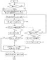
図7及び図8は、図1のエアロゾル生成装置1の動作を説明するためのフローチャートである。操作部14の操作等によってエアロゾル生成装置1の電源がONされると(ステップS0:YES)、MCU50は、メモリ50aに記憶している吸引回数又は累積放電時間に基づいて、香味源33の目標温度Tcap_targetを決定(設定)する(ステップS31)。(Operation of aerosol generator)
7 and 8 are flowcharts for explaining the operation of the aerosol generator 1 of FIG. When the power of the aerosol generator 1 is turned on by the operation of the
次に、MCU50は、現時点での香味源33の温度Tcap_senseを温度検出用素子T1(又は温度検出用素子T3)の出力に基づいて取得する(ステップS32)。Next, the
MCU50は、温度Tcap_senseと目標温度Tcap_targetに基づいて、香味源33を加熱するための第二負荷31への放電を制御する(ステップS33)。具体的には、MCU50は、温度Tcap_senseが目標温度Tcap_targetに収束するように、PID(Proportional−Integral−Differential )制御、又は、ON/OFF制御によって第二負荷31へ電力供給を行う。The
PID制御は、温度Tcap_senseと目標温度Tcap_targetの差をフィードバックし、そのフィードバック結果に基づいて、温度Tcap_senseが目標温度Tcap_targetに収束するよう電力制御を行うものである。PID制御によれば、温度Tcap_senseを目標温度Tcap_targetに高精度に収束させることができる。なお、MCU50は、PID制御に代えてP(Proportional)制御やPI(Proportional−Integral)制御を用いてもよい。PID control, feeding back the difference between the temperatureT Cap_sense and the target temperatureT Cap_target, based on the feedback result, and performs power control such that the temperatureT Cap_sense converges to the target temperatureT cap_target. According to the PID control, the temperature Tcap_sense can be converged to the target temperature Tcap_target with high accuracy. The
ON/OFF制御は、温度Tcap_senseが目標温度Tcap_target未満の状態では第二負荷31への電力供給を行い、温度Tcap_senseが目標温度Tcap_target以上の状態では、温度Tcap_senseが目標温度Tcap_target未満になるまで第二負荷31への電力供給を停止する制御である。ON/OFF制御によれば、PID制御よりも香味源33の温度を早く上昇させることができる。このため、後述のエアロゾルの生成要求が検知される前の段階にて、温度Tcap_senseが目標温度Tcap_targetに到達する可能性を高めることができる。ON / OFF control is in a state below the temperatureT Cap_sense the target temperatureT Cap_target performs power supply to the
ステップS33の後、MCU50は、エアロゾルの生成要求の有無を判定する(ステップS34)。MCU50は、エアロゾルの生成要求を検出しなかった場合(ステップS34:NO)には、ステップS35にて、エアロゾルの生成要求が行われていない時間(以下、無操作時間と記載)の長さを判定する。MCU50は、無操作時間が所定時間に達していた場合(ステップS35:YES)には、第二負荷31への放電を終了して(ステップS36)、消費電力を低減させたスリープモードへと移行する(ステップS37)。MCU50は、無操作時間が所定時間未満であった場合(ステップS35:NO)には、ステップS32に処理を移行する。 After step S33, the
MCU50は、エアロゾルの生成要求を検知すると(ステップS34:YES)、ユーザに吸引されている流体の流量を取得し(ステップS38)、取得した流量が第一所定値を超えるか否かを判定する(ステップS39)。 When the
MCU50は、流量が第一所定値以下の場合(ステップS39:NO)には、ステップS41に処理を移行する。MCU50は、流量が第一所定値を超える場合(ステップS39:YES)には、ステップS31にて決定した目標温度Tcap_targetを上昇し、霧化電力Pliquidの設定値を、上記の前提条件にしたがって予め決められた第二所定値から増加する処理を実行する(ステップS40)。When the flow rate is equal to or less than the first predetermined value (step S39: NO), the
メモリ50aには、流量と第一所定値との差分ΔFと、目標温度Tcap_targetの温度上昇幅ΔTと、霧化電力Pliquidの電力増加幅ΔPと、を対応付けたテーブルが記憶されている。このテーブルは、上述したように、香味濃度Ctが目標値となるように生成されたものである。The
ステップS40において、MCU50は、ステップS38にて取得した流量から第一所定値を減算して差分ΔFを求め、この差分ΔFに対応する温度上昇幅ΔT及び電力増加幅ΔPをこのテーブルから読み出し、読み出したデータにしたがって目標温度の上昇と霧化電力の増加を行う。ステップS40にて目標温度の上昇が行われることで、エアロゾル生成要求が検知される直前の時点と比べると、香味源33の温度は上昇する。 In step S40, the
ステップS40の後、MCU50は、ステップS41に処理を移行する。ステップS41において、MCU50は、霧化電力Pliquidを第一負荷21に供給して第一負荷21の加熱(エアロゾル源22を霧化するための加熱)を行い、エアロゾルの生成を開始する。ここで第一負荷21に供給される霧化電力Pliquidは、ステップS39の判定がNOであった場合には、上記の第二所定値となり、ステップS39の判定がYESであった場合には、“第二所定値+ΔP”となる。After step S40, the
ステップS41での第一負荷21の加熱開始後、MCU50は、エアロゾルの生成要求が終了されていない場合(ステップS42:NO)には、エアロゾルの生成要求の継続時間が上限値tupper未満であれば(ステップS43:YES)、第一負荷21の加熱を継続する。MCU50は、エアロゾルの生成要求の継続時間が上限値tupperに達した場合(ステップS43:NO)と、エアロゾルの生成要求が終了された場合(ステップS42:YES)には、第一負荷21と第二負荷31への電力供給を停止する(ステップS44)。After the start of heating of the
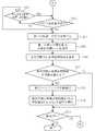
ステップS44の後、MCU50は、ステップS41で開始した第一負荷21の加熱期間中における、第一負荷21へ供給した霧化電力Pliquidの供給時間tsenceを取得する(ステップS45)。そして、MCU50は、メモリ50aに記憶している吸引回数又は累積放電時間を更新する(ステップS46)。After step S44, the
累積放電時間は、ステップS45で取得した供給時間tsenceを、前回の吸引までの供給時間tsenceの累積値に加算することで更新される。吸引回数は、MCU50に内蔵されるカウンタのカウンタ値を1つ進めることで更新される。Accumulated discharge time, a supply timet sence obtained in step S45, is updated by adding the accumulated value of the supply timet sence up to the previous suction. The number of suctions is updated by advancing the counter value of the counter built in the
次に、MCU50は、更新後の吸引回数又は累積放電時間が閾値を超えるか否かを判定する(ステップS47)。MCU50は、更新後の吸引回数又は累積放電時間が閾値以下の場合(ステップS47:NO)には、ステップS50に処理を移行する。 Next, the
MCU50は、更新後の吸引回数又は累積放電時間が閾値を超える場合(ステップS47:YES)には、第2カートリッジ30の交換を促す通知を第1通知部45及び第2通知部46に行わせる(ステップS48)。そして、MCU50は、メモリ50aの吸引回数又は累積放電時間を初期値(=0)にリセットし、目標温度Tcap_targetを初期化する(ステップS49)。目標温度Tcap_targetの初期化とは、メモリ50aに記憶しているその時点での目標温度Tcap_targetを設定値から除外することを意味する。When the number of suctions or the cumulative discharge time after the update exceeds the threshold value (step S47: YES), the
ステップS49の後、MCU50は、電源がオフされなければ(ステップS50:NO)、ステップS1に処理を戻し、電源がオフされたら(ステップS50:YES)、処理を終了する。 After step S49, the
(実施形態の効果)
以上のように、エアロゾル生成装置1によれば、エアロゾルに付加される香味成分量を高い値で安定させることができ、商品価値を高めることができる。
また、エアロゾル生成装置1によれば、ユーザの吸引の流量が第一所定値を超える場合であっても、その流量に基づいて、香味源33の温度とエアロゾル生成のために第一負荷21に供給される電力とが増加される。このため、装置が前提としている吸引動作より強い吸引が行われた場合でも、香味濃度Ctを目標値に維持することができる。この結果、ユーザの吸引動作の違いに関係なく、所望の香喫味をユーザに提供できる。(Effect of embodiment)
As described above, according to the aerosol generator 1, the amount of the flavor component added to the aerosol can be stabilized at a high value, and the commercial value can be enhanced.
Further, according to the aerosol generation device 1, even when the flow rate of suction by the user exceeds the first predetermined value, the temperature of the
図7のステップS40では、目標温度の上昇と霧化電力の増加の両方を行うものとしているが、目標温度のみを上昇させる構成としてもよい。この構成では、流量と第一所定値との差分ΔFと、目標温度Tcap_targetの温度上昇幅ΔTと、を対応付けたテーブルをメモリ50aに記憶しておく。このテーブルは、香味濃度Ctが目標値となるように生成されたものである。MCU50は、このテーブルにしたがって目標温度を上昇させればよい。この構成であっても、香味濃度Ctを目標値に維持することができ、所望の香喫味をユーザに提供できる。In step S40 of FIG. 7, both the target temperature and the atomizing power are increased, but only the target temperature may be increased. In this configuration, the
ステップS40において目標温度のみを上昇させる場合には、目標温度の上昇と霧化電力の増加の両方を行う場合と比べると、同じ流量であっても、目標温度の上昇幅を大きくする必要がある。つまり、目標温度の上昇と霧化電力の増加の両方を行う構成によれば、目標温度の上昇幅を小さくすることができる。このように目標温度の上昇幅を小さくできることで、香味源33の温度を早期に目標温度まで到達させやすくなる。この結果、吸引の早期の段階で、香味濃度Ctを目標値に収束させることができ、吸引開始から吸引終了までの間、ユーザに安定した香喫味を提供することができる。 When only the target temperature is raised in step S40, it is necessary to increase the increase range of the target temperature even at the same flow rate as compared with the case where both the target temperature is raised and the atomizing power is increased. .. That is, according to the configuration in which both the target temperature is increased and the atomizing power is increased, the increase range of the target temperature can be reduced. By reducing the rate of increase in the target temperature in this way, it becomes easier for the temperature of the
または、図7のステップS40では、流量の大きさに基づいて、目標温度の上昇と霧化電力の増加の両方を行う処理と、目標温度のみを上昇させる処理と、を選択するようにしてもよい。例えば、MCU50は、差分ΔFが閾値以下となっており、香味源33の温度上昇だけで香味濃度Ctを目標値にできるような場合には、目標温度の上昇のみを行う。一方、MCU50は、差分ΔFが閾値を超えており、香味源33の温度上昇だけでは香味濃度Ctを目標値にすることが難しい場合には、目標温度の上昇と霧化電力の増加の両方を行う。このような処理を行う場合には、閾値以下の差分ΔFと温度上昇幅ΔTを対応付けたテーブルと、閾値を超える差分ΔFと温度上昇幅ΔT及び電力増加幅ΔPを対応付けたテーブルと、をメモリ50aに記憶しておく。MCU50は、差分ΔFの大きさに応じて、どちらかのテーブルを参照して、目標温度の上昇、又は、目標温度の上昇と霧化電力の増加を行えばよい。 Alternatively, in step S40 of FIG. 7, a process of both increasing the target temperature and increasing the atomizing power and a process of increasing only the target temperature may be selected based on the magnitude of the flow rate. Good. For example, in the
なお、第一所定値を中心とする流量の所定範囲を設定しておき、流量がこの所定範囲に入る場合を上記の前提条件としてもよい。この場合には、MCU50は、ステップS39の判定において、吸引時の流量が上記所定範囲内であれば、目標温度の上昇と霧化電力の増加は行わず、吸引時の流量が上記所定範囲を超えていれば、この所定範囲の最大値と流量との差を上記の差分ΔFとして求め、この差分ΔFに応じて目標温度の上昇と霧化電力の増加を行うようにすればよい。 A predetermined range of the flow rate centered on the first predetermined value may be set, and the case where the flow rate falls within the predetermined range may be set as the above precondition. In this case, in the determination of step S39, if the flow rate at the time of suction is within the above-mentioned predetermined range, the
(エアロゾル生成装置の第一変形例)
図9は、図1のエアロゾル生成装置1の動作の第一変形例を説明するためのフローチャートである。図9のステップS41以降の処理は、図8と同じであるため図示を省略する。図9は、ステップS31とステップS32の間にステップS31a、ステップS31b、及びステップS31cが追加された点と、ステップS38がステップS38aに変更された点と、ステップS40がステップS40aに変更された点と、を除いては、図7と同じである。以下、図7に対する変更点を中心に説明する。(First modification of aerosol generator)
FIG. 9 is a flowchart for explaining a first modification of the operation of the aerosol generation device 1 of FIG. Since the processing after step S41 in FIG. 9 is the same as that in FIG. 8, the illustration is omitted. FIG. 9 shows a point where step S31a, step S31b, and step S31c are added between steps S31 and S32, a point where step S38 is changed to step S38a, and a point where step S40 is changed to step S40a. It is the same as FIG. 7 except that. Hereinafter, the changes to FIG. 7 will be mainly described.
ステップS31の後のステップS31aにおいて、MCU50は、前回に行われたユーザの吸引における流量の情報をメモリ50aから取得する。次のステップS31bにおいて、MCU50は、前回の吸引時の流量が第一所定値を超えるか否かを判定する。 In step S31a after step S31, the
MCU50は、前回の吸引時の流量が第一所定値を超える場合(ステップS31b:YES)には、その流量に基づいて、ステップS31で決定した目標温度Tcap_targetを調整する(ステップS31c)。なお、エアロゾル生成装置1が初めて使用されたタイミングでは、前回の吸引時の流量がメモリ50aに記憶されていない。このため、この場合にはステップS31a、ステップS31b、及びステップS31cの処理は省略される。When the flow rate at the time of the previous suction exceeds the first predetermined value (step S31b: YES), the
メモリ50aには、流量と第一所定値との差分ΔFと、目標温度Tcap_targetの温度上昇幅ΔTと、霧化電力Pliquidの電力増加幅ΔPと、を対応付けたテーブルが記憶されている。ステップS31cにおいて、MCU50は、前回の吸引時の流量から第一所定値を減算して差分ΔFを算出する。更に、MCU50は、この差分ΔFに対応する温度上昇幅ΔTを上記のテーブルから読み出し、読み出した温度上昇幅ΔTを、ステップS31にて決定した目標温度に加算して、目標温度の調整を行う。ステップS31bの判定がNOの場合と、ステップS31cの後には、ステップS32の処理が行われる。The
MCU50は、ステップS34においてエアロゾルの生成要求を検知すると(ステップS34:YES)、今回のユーザの吸引における流量を取得し、この流量を最新の流量の情報としてメモリ50aに記憶する(ステップS38a)。ここで記憶される最新の流量が、次回のステップS31aの処理で取得される、前回の吸引時の流量となる。 When the
ステップS38aの後のステップS39において、MCU50は、ステップS38aにて取得した流量が第一所定値を超えるか否かを判定する。MCU50は、ステップS38aにて取得した流量が第一所定値を超える場合(ステップS39:YES)には、その流量と第一所定値との差分に対応する電力増加幅ΔPを上記のテーブルから取得する。そして、MCU50は、霧化電力Pliquidの設定値を、取得した電力増加幅ΔPと第二所定値の合計値に変更することで、霧化電力の増加を行う(ステップS40a)。ステップS39の判定がNOであった場合と、ステップS40aの処理の後には、ステップS41以降の処理が行われる。In step S39 after step S38a, the
以上の第一変形例の動作によれば、ユーザの吸引を検知するよりも前に、前回の吸引における流量に基づいて香味源33の目標温度が調整され、香味源33の温度がその目標温度に収束するように電源12から第二負荷31への放電制御が開始される。このため、吸引がなされる前の段階で、香味濃度Ctを目標値とするための香味源33の温度の制御が可能になる。 According to the operation of the above first modification, the target temperature of the
香味源33は、第二負荷31によって直接的に加熱されるのではなく、第2カートリッジ30の外装体を介して間接的に加熱される。そのため、香味源33の温度を所望の値にまで上昇させるには、時間が必要になる場合がある。このように、香味源33の温度応答性が低い場合でも、前回の吸引時の流量に基づいて目標温度を調整し、エアロゾル生成の前に、香味源33の温度をその目標温度まで収束させる制御を行うことで、ユーザの吸引が開始された時点において、香味源33の温度を、その吸引時の流量に応じた最適な香味源33の温度に近づけておくことができる。同じユーザが吸引を行う前提にたつと、前回の吸引の流量と、今回の吸引の流量とで大きな差が生じるわけではない。このため、前回の吸引時の流量に基づいて香味源33の温度を制御することで、吸引開始の早期の段階から目標に近い香喫味をユーザに提供できる。 The
なお、第一変形例の動作では、香味源33の温度を調整するために用いる流量と、霧化電力を調整するために用いる流量とが、異なるタイミングにて取得されるものである。しかし、前回の吸引の流量と、今回の吸引の流量とで大きな差が生じるわけではない。このことから、今回の吸引時の流量と、前回の吸引時の流量とに差があった場合でも、今回の吸引時の流量に応じた最適な目標温度及び霧化電力(香味濃度Ctを目標値とするために必要な目標温度及び霧化電力)と、ステップS31cで上昇後の目標温度及びステップS40aで増加後の霧化電力との乖離は少なくできる。この結果、目標の香喫味をユーザに提供可能となる。 In the operation of the first modification, the flow rate used for adjusting the temperature of the
第一変形例の動作は、ステップS39及びステップS40aを削除し、ステップS38aの後にステップS41に移行する動作にも変形できる。この動作によれば、前回の吸引の流量に基づいて、次の吸引が開始される前に、香味源33の温度が調整される。このため、吸引開始の早期の段階から目標に近い香喫味をユーザに提供できるようになる。 The operation of the first modification can be modified to the operation of deleting step S39 and step S40a and shifting to step S41 after step S38a. According to this operation, the temperature of the
第一変形例の動作においては、エアロゾル生成装置1における最初の吸引で流量大だった場合には、霧化電力のみが増加されることになる。しかし、次の吸引開始前には、そのときの流量に応じて目標温度が上昇される。このため、次の吸引時に流量大だった場合には、香味源33の温度上昇且つエアロゾル生成量の増加となり、香味濃度Ctを目標値に近づけることが可能である。 In the operation of the first modification, when the flow rate is large at the first suction in the aerosol generation device 1, only the atomizing power is increased. However, before the start of the next suction, the target temperature is raised according to the flow rate at that time. Therefore, when the flow rate is large at the time of the next suction, the temperature of the
(エアロゾル生成装置の第二変形例)
図10は、図1のエアロゾル生成装置1の動作の第二変形例を説明するためのフローチャートである。図10のステップS41以降の処理は、図8と同じであるため図示を省略する。図10は、ステップS31とステップS32の間にステップS31d及びステップS31eが追加された点と、ステップS38がステップS38b及びステップS38cに変更された点と、を除いては、図7と同じである。以下、図7に対する変更点を中心に説明する。(Second modification of aerosol generator)
FIG. 10 is a flowchart for explaining a second modification of the operation of the aerosol generation device 1 of FIG. Since the processing after step S41 in FIG. 10 is the same as that in FIG. 8, the illustration is omitted. FIG. 10 is the same as FIG. 7 except that step S31d and step S31e are added between step S31 and step S32, and step S38 is changed to step S38b and step S38c. .. Hereinafter, the changes to FIG. 7 will be mainly described.
ステップS31の後のステップS31dにおいて、MCU50は、流量学習データがメモリ50aに記憶済みか否かを判定する。流量学習データとは、前回以前に行われたユーザの過去の複数回の吸引における流量の情報に基づいて生成される、ユーザの吸引動作の傾向を示すデータである。例えば、過去の複数回の吸引における流量の平均値、中央値、又は最頻値等を流量学習データとして生成することができる。この流量学習データは、所定の数(=2以上の自然数)の流量の取得が行われるまで、つまり所定回数の吸引が行われるまでは生成されない。後述のステップS38bにおいて、MCU50は、所定回数以上分の流量が取得されると、この所定回数分の流量に基づいて流量学習データを生成してメモリ50aに記憶する。 In step S31d after step S31, the
MCU50は、メモリ50aに流量学習データを記憶済みであれば(ステップS31d:YES)、この流量学習データに基づいて、ステップS31で決定した目標温度と霧化電力の調整処理を行う(ステップS31e)。 If the flow rate learning data is stored in the
具体的には、MCU50は、流量学習データが第一所定値以下の場合には、ステップS31で決定した目標温度をそのまま維持し、霧化電力を第二所定値に設定する。MCU50は、流量学習データが第一所定値を超える場合には、流量学習データから第一所定値を減算して上記の差分ΔFを算出する。そして、MCU50は、この差分ΔFと上記のテーブルとに基づいて、ステップS31で決定した目標温度を温度上昇幅ΔTだけ上昇させ、霧化電力を第二所定値から電力増加幅ΔPだけ増加させる。ステップS31dの判定がNOの場合と、ステップS31eの処理の後には、ステップS32の処理が行われる。 Specifically, when the flow rate learning data is equal to or less than the first predetermined value, the
MCU50は、ステップS34においてエアロゾルの生成要求を検知すると(ステップS34:YES)、今回のユーザの吸引における流量を取得し、この流量をメモリ50aに記憶する(ステップS38b)。このステップS38bにおいて、MCU50は、必要な数以上の流量の情報がメモリ50aに記憶されている場合には、メモリ50aに記憶済みのすべての流量に基づいて流量学習データを生成し、これをメモリ50aに記憶する。 When the
ステップS38bの後のステップS38cにおいて、MCU50は、ステップS31で決定された目標温度の上昇と、霧化電力の増加と、が行われたか否かを判定する。ステップS31eにおいて目標温度の上昇と霧化電力の増加が行われていれば(ステップS38c:YES)、MCU50は、ステップS41の処理を行う。 In step S38c after step S38b, the
目標温度の上昇と霧化電力の増加が行われていない場合(ステップS38c:NO)には、MCU50は、ステップS38bにて取得した今回の吸引時の流量が第一所定値を超えるか否かを判定する(ステップS39)。 When the target temperature is not raised and the atomizing power is not increased (step S38c: NO), the MCU50 determines whether or not the flow rate at the time of suction acquired in step S38b exceeds the first predetermined value. Is determined (step S39).
MCU50は、ステップS38bにて取得した流量が第一所定値を超える場合(ステップS39:YES)には、その流量と第一所定値との差分に対応する温度上昇幅ΔT及び電力増加幅ΔPを上記のテーブルから取得する。そして、MCU50は、これら温度上昇幅ΔT及び電力増加幅ΔPに基づいて、目標温度を上昇させ霧化電力を増加させる(ステップS40)。ステップS39の判定がNOであった場合と、ステップS40の処理の後には、ステップS41の処理が行われる。 When the flow rate acquired in step S38b exceeds the first predetermined value (step S39: YES), the
以上の第二変形例の動作によれば、ユーザの吸引を検知するよりも前に、前回以前の過去複数回の吸引における流量に基づいて、香味源33の目標温度と霧化電力が調整される。このため、吸引がなされる前の段階で、香味濃度Ctを目標値とするための香味源33の温度の制御が可能になる。また、吸引がなされる前の段階で、霧化電力の調整も終了されるため、吸引が開始されてすぐに、香味濃度Ctを目標値とするための霧化電力の第一負荷21への供給を開始できる。この結果、吸引後の早期の段階で、所望の香喫味をユーザに提供できる。また、過去複数回の流量に基づく流量学習データにしたがって目標温度と霧化電力の調整が行われるため、第一変形例の動作と比較すると、目標温度の調整精度を高めることができる。 According to the operation of the second modification described above, the target temperature of the
(エアロゾル生成装置の第三変形例)
ここまでの説明では、ユーザによる吸引の流量に基づいて目標温度と霧化電力の少なくとも一方を増加させることで、流量が多くなった場合でも、香味濃度Ctが低下するのを防ぐものとした。しかし、ユーザによる吸引の流量が第一所定値より少ない場合(装置の想定よりも弱い吸引が行われた場合)には、流体量Wfに占める空気量が減少することで、香味濃度Ctが目標値よりも高くなる。エアロゾル生成装置1の商品価値を高める上では、香味濃度Ctが低くなることを少なくとも避ける必要がある。つまり、香味濃度Ctが目標値よりも高くなる状況については、許容することができる。しかし、エアロゾル生成装置1の商品価値を更に高めるのであれば、ユーザによる吸引の流量が第一所定値より少ない場合に、目標温度の減少と霧化電力の減少の少なくとも一方を行って、香味濃度Ctが目標値となるよう制御することが好ましい。(Third modification example of aerosol generator)
In the above description, by increasing at least one of the target temperature and the atomizing power based on the flow rate of suction by the user, it is possible to prevent the flavor concentration Ct from decreasing even when the flow rate increases. However, when the flow rate of suction by the user is less than the first predetermined value (when suction is performed weaker than the device assumes), the amount of air in the fluid amount Wf is reduced, so that the flavor concentration Ct is the target. Higher than the value. In order to increase the commercial value of the aerosol generator 1, it is necessary to at least avoid lowering the flavor concentration Ct. That is, the situation where the flavor concentration Ct becomes higher than the target value can be tolerated. However, if the commercial value of the aerosol generator 1 is to be further enhanced, when the flow rate of suction by the user is less than the first predetermined value, at least one of the reduction of the target temperature and the reduction of the atomizing power is performed to reduce the flavor concentration. It is preferable to control so that Ct becomes a target value.
例えば、図7の動作であれば、ステップS39の判定がNOであり、流量が第一所定値未満である場合には、流量と第一所定値の差分に基づいて、目標温度と霧化電力を低下させることが好ましい。 For example, in the operation of FIG. 7, if the determination in step S39 is NO and the flow rate is less than the first predetermined value, the target temperature and the atomizing power are based on the difference between the flow rate and the first predetermined value. It is preferable to reduce.
ここまで説明してきたエアロゾル生成装置1では、1回の吸引あたりの流量に基づいて、目標温度と霧化電力の少なくとも一方を増加させるものとした。この変形例として、ユーザによる吸引の流量の累積値に基づいて、目標温度と霧化電力の少なくとも一方を制御するようにしてもよい。例えば、流量の累積値が前提条件よりも多い場合には、目標温度と霧化電力の少なくとも一方を増加させて香味濃度が目標値となるよう制御すればよい。この変形例では、香味源33の残量が枯渇した時点で、流量の累積値を0にリセットすることで、1つの第2カートリッジ30を消費中のユーザの吸引の仕方に応じた適切な制御が可能になる。または、エアロゾル源22の残量が枯渇した時点で、流量の累積値を0にリセットすることで、1つの第1カートリッジ20を消費中のユーザの吸引の仕方に応じた適切な制御が可能になる。 In the aerosol generator 1 described so far, at least one of the target temperature and the atomizing power is increased based on the flow rate per suction. As an example of this modification, at least one of the target temperature and the atomization power may be controlled based on the cumulative value of the suction flow rate by the user. For example, when the cumulative value of the flow rate is larger than the precondition, at least one of the target temperature and the atomizing power may be increased to control the flavor concentration to be the target value. In this modification, when the remaining amount of the
ここまで説明してきたエアロゾル生成装置1では、吸引回数又は累積放電時間に基づいて、香味源33の目標温度を設定するものとした。この吸引回数又は累積放電時間は、前述したように、香味源33に含まれる香味成分の残量に反比例するパラメータである。したがって、エアロゾルの生成のために第一負荷21に供給した電力量等のパラメータに基づいて、香味源33の香味成分残量を演算によって導出し、この香味成分残量に基づいて、香味源33の目標温度を設定するようにしてもよい。 In the aerosol generator 1 described so far, the target temperature of the
また、ここまで説明してきたエアロゾル生成装置1において、第一負荷21を、超音波などによってエアロゾル源22を加熱することなくエアロゾル源22を霧化することのできる素子で構成してもよい。第一負荷21に用いることができる素子は、上述したヒータ、超音波素子に限られず、電源12から供給される電力を消費することでエアロゾル源22の霧化が可能な素子であればさまざまな素子又はその組合せを利用することができる。 Further, in the aerosol generation device 1 described so far, the
本明細書には少なくとも以下の事項が記載されている。なお、括弧内には、上記した実施形態において対応する構成要素等を示しているが、これに限定されるものではない。 At least the following matters are described in this specification. The components and the like corresponding to the above-described embodiments are shown in parentheses, but the present invention is not limited thereto.
(1)
香味が付加されたエアロゾルを吸引可能なエアロゾル生成装置(エアロゾル生成装置1)の電源ユニット(電源ユニット10)であって、
エアロゾル源(エアロゾル源22)を霧化可能な霧化器(第一負荷21)と、上記エアロゾル源から生成されたエアロゾルに香味成分を付加する香味源(香味源33)を加熱可能なヒータ(第二負荷31)と、に放電可能な電源(電源12)と、
ユーザによる吸引の流量を取得可能に構成される処理装置(MCU50のプロセッサ)と、を備え、
上記処理装置は、
ユーザの吸引を検知した場合に上記電源から上記霧化器への放電を行ってエアロゾルを生成し、
ユーザに吸引される流体に含まれる香味成分の濃度(香味濃度Ct)が目標値となるように、上記流量に基づいて上記ヒータに放電する電力を制御するエアロゾル生成装置の電源ユニット。(1)
It is a power supply unit (power supply unit 10) of an aerosol generator (aerosol generator 1) capable of sucking an aerosol to which a flavor is added.
An atomizer (first load 21) capable of atomizing an aerosol source (aerosol source 22) and a heater (flavor source 33) capable of heating a flavor source (flavor source 33) for adding a flavor component to the aerosol generated from the aerosol source. A second load 31), a power source that can be discharged to (power source 12), and
It is equipped with a processing device (processor of MCU50) configured to be able to acquire the flow rate of suction by the user.
The above processing device
When the user's suction is detected, the power supply discharges the atomizer to generate an aerosol.
A power supply unit of an aerosol generator that controls the electric power discharged to the heater based on the flow rate so that the concentration of the flavor component (flavor concentration Ct) contained in the fluid sucked by the user becomes a target value.
(1)によれば、ユーザによる吸引の流量に基づいてヒータに放電する電力が制御されるため、ユーザの吸引の仕方に違いがあっても、一定の香喫味をユーザに提供することができる。なお、上記の“ユーザに吸引される流体に含まれる香味成分”には、香味源に含まれる香味成分だけでなく、エアロゾル源に含まれる香味成分が含まれる場合もある。 According to (1), since the electric power discharged to the heater is controlled based on the flow rate of suction by the user, it is possible to provide the user with a certain flavor and taste even if there is a difference in the suction method of the user. .. The above-mentioned "flavor component contained in the fluid sucked by the user" may include not only the flavor component contained in the flavor source but also the flavor component contained in the aerosol source.
(2)
(1)記載のエアロゾル生成装置の電源ユニットであって、
上記処理装置は、
ユーザの吸引を検知するよりも前に、上記香味源の温度が目標温度に収束するように、上記電源から上記ヒータへの放電制御を開始し、
ユーザの吸引を検知した場合に、その吸引時の上記流量に基づいて上記目標温度を調整するエアロゾル生成装置の電源ユニット。(2)
(1) The power supply unit of the aerosol generator described above.
The above processing device
Before detecting the suction of the user, the discharge control from the power supply to the heater is started so that the temperature of the flavor source converges to the target temperature.
A power supply unit of an aerosol generator that adjusts the target temperature based on the flow rate at the time of suction when the user's suction is detected.
(2)によれば、ユーザの吸引中に目標温度が調整されてヒータへ放電される電力が制御される。このため、香喫味を早期に目標の状態にすることができる。 According to (2), the target temperature is adjusted during suction by the user, and the electric power discharged to the heater is controlled. Therefore, the flavor and taste can be brought to the target state at an early stage.
(3)
(2)記載のエアロゾル生成装置の電源ユニットであって、
上記処理装置は、上記吸引時の流量が基準値(第一所定値)を超える場合に、上記目標温度を上昇させるエアロゾル生成装置の電源ユニット。(3)
(2) The power supply unit of the aerosol generator described above.
The processing device is a power supply unit of an aerosol generating device that raises the target temperature when the flow rate at the time of suction exceeds a reference value (first predetermined value).
(3)によれば、吸引の流量が多い場合には香味源の温度が上がる。このため、ユーザの口に輸送される流体に占める香味成分を増やすことができ、目標の香喫味をユーザに提供できる。 According to (3), the temperature of the flavor source rises when the suction flow rate is large. Therefore, the flavor component in the fluid transported to the user's mouth can be increased, and the target flavor and taste can be provided to the user.
(4)
(1)記載のエアロゾル生成装置の電源ユニットであって、
上記処理装置は、
ユーザの吸引を検知するよりも前に、過去の吸引における上記流量に基づいて上記香味源の目標温度を決定し、且つ、上記香味源の温度がその目標温度に収束するように上記電源から上記ヒータへの放電制御を開始するエアロゾル生成装置の電源ユニット。(4)
(1) The power supply unit of the aerosol generator described above.
The above processing device
Prior to detecting the user's suction, the target temperature of the flavor source is determined based on the flow rate in the past suction, and the temperature of the flavor source converges to the target temperature from the power source. The power supply unit of the aerosol generator that starts the discharge control to the heater.
(4)によれば、ユーザの吸引の実績に応じてヒータへの放電制御が行われるため、吸引がなされる前の段階で、香味源の温度を最適化できる。この結果、吸引開始の早期の段階から目標の香喫味をユーザに提供できる。 According to (4), since the discharge control to the heater is performed according to the user's suction performance, the temperature of the flavor source can be optimized before the suction is performed. As a result, the target flavor and taste can be provided to the user from the early stage of the start of suction.
(5)
(4)記載のエアロゾル生成装置の電源ユニットであって、
上記過去の吸引は、前回の吸引であるエアロゾル生成装置の電源ユニット。(5)
(4) The power supply unit of the aerosol generator described above.
The above past suction is the power supply unit of the aerosol generator, which is the previous suction.
(5)によれば、前回の吸引における流量に基づいて目標温度が決定されるため、処理を簡素化することができる。 According to (5), since the target temperature is determined based on the flow rate in the previous suction, the process can be simplified.
(6)
(1)から(5)のいずれか1つに記載のエアロゾル生成装置の電源ユニットであって、
上記処理装置は、更に、エアロゾル生成のために上記霧化器に放電する電力を、上記濃度が目標値となるように、上記流量に基づいて制御するエアロゾル生成装置の電源ユニット。(6)
The power supply unit of the aerosol generator according to any one of (1) to (5).
The processing device is a power supply unit of an aerosol generating device that further controls the electric power discharged to the atomizer for aerosol generation based on the flow rate so that the concentration becomes a target value.
(6)によれば、香味源の温度制御だけでは目標の香喫味を達成できないような吸引がなされた場合であっても、エアロゾルの生成量の調整によって、目標の香喫味を達成できる。 According to (6), even when suction is performed so that the target flavor and taste cannot be achieved only by controlling the temperature of the flavor source, the target flavor and taste can be achieved by adjusting the amount of aerosol produced.
(7)
(6)記載のエアロゾル生成装置の電源ユニットであって、
上記処理装置は、過去の吸引における上記流量に基づいて、次のエアロゾル生成のために上記霧化器に供給する電力を制御するエアロゾル生成装置の電源ユニット。(7)
(6) The power supply unit of the aerosol generator according to the above.
The processing apparatus is a power supply unit of an aerosol generator that controls the electric power supplied to the atomizer for the next aerosol generation based on the flow rate in the past suction.
(7)によれば、過去の吸引における流量に基づいてエアロゾルの生成量が調整される。このため、吸引がなされる前の段階で、エアロゾルの生成量を最適化でき、吸引開始の早期の段階から目標の香喫味をユーザに提供できる。 According to (7), the amount of aerosol produced is adjusted based on the flow rate in the past suction. Therefore, the amount of aerosol produced can be optimized before the suction is performed, and the target flavor and taste can be provided to the user from the early stage of the start of suction.
(8)
(6)又は(7)記載のエアロゾル生成装置の電源ユニットであって、
上記処理装置は、上記流量が基準値(第一所定値)を超える場合に、上記霧化器に供給する電力を増加させるエアロゾル生成装置の電源ユニット。(8)
The power supply unit of the aerosol generator according to (6) or (7).
The processing device is a power supply unit of an aerosol generator that increases the electric power supplied to the atomizer when the flow rate exceeds a reference value (first predetermined value).
(8)によれば、吸引の流量が多い場合にはエアロゾルの生成量が増えることで、エアロゾルに付加される香味成分を増やすことができる。この香味成分の増加と、香味源の温度制御による香味成分の調整とを併せて行うことで、目標の香喫味をユーザに提供できる。 According to (8), when the suction flow rate is large, the amount of aerosol produced increases, so that the flavor component added to the aerosol can be increased. By combining this increase in the flavor component and the adjustment of the flavor component by controlling the temperature of the flavor source, the target flavor and taste can be provided to the user.
1 エアロゾル生成装置
T1,T2,T3 温度検出用素子
10 電源ユニット
11a トップ部
11b ボトム部
11 電源ユニットケース
12 電源
14 操作部
15 吸気センサ
20 第1カートリッジ
21 第一負荷
31 第二負荷
22 エアロゾル源
23 リザーバ
24 ウィック
25 エアロゾル流路
26a カートリッジ収容部
26b 連通路
26 エンドキャップ
27 カートリッジケース
30 第2カートリッジ
32 吸口
33 香味源
41 放電端子
42 空気供給部
43 充電端子
45 第1通知部
46 第2通知部
50a メモリ
50 MCU
51 DC/DCコンバータ
52,54 電圧センサ
53,55 電流センサ
55A 充電IC1 Aerosol generator T1, T2, T3
51 DC /
Claims (6)
Translated fromJapaneseエアロゾル源を霧化可能な霧化器と、前記エアロゾル源から生成されたエアロゾルに香味成分を付加する香味源を加熱可能なヒータと、に放電可能な電源と、
ユーザによる吸引の流量を取得可能に構成される処理装置と、を備え、
前記処理装置は、
ユーザの吸引を検知した場合に前記電源から前記霧化器への放電を行ってエアロゾルを生成し、
ユーザに吸引される流体に含まれる香味成分の濃度が目標値となるように、前記流量に基づいて前記ヒータに放電する電力を制御し、
前記処理装置は、更に、
ユーザの吸引を検知するよりも前に、前記香味源の温度が目標温度に収束するように、前記電源から前記ヒータへの放電制御を開始し、
ユーザの吸引を検知した場合に、当該吸引時の前記流量に基づいて前記目標温度を調整するエアロゾル生成装置の電源ユニット。A power supply unit for an aerosol generator capable of sucking aerosols with added flavor.
An atomizer capable of atomizing an aerosol source, a heater capable of heating a flavor source that adds a flavor component to the aerosol generated from the aerosol source, and a power source capable of discharging the aerosol.
It is equipped with a processing device configured to be able to acquire the flow rate of suction by the user.
The processing device is
When the suction of the user is detected, the power source discharges the atomizer to generate an aerosol.
The electric power discharged to the heater is controlled based on the flow rate so that the concentration of the flavor component contained in the fluid sucked by the user becomes a target value.
The processing device further
Before detecting the suction of the user, the discharge control from the power source to the heater is started so that the temperature of the flavor source converges to the target temperature.
A power supply unit of an aerosol generatorthat adjusts the target temperature based on the flow rate at the time of suction when the suction of the user is detected.
前記処理装置は、前記吸引時の流量が基準値を超える場合に、前記目標温度を上昇させるエアロゾル生成装置の電源ユニット。The power supply unit of the aerosol generator according to claim1.
The processing device is a power supply unit of an aerosol generating device that raises the target temperature when the flow rate at the time of suction exceeds a reference value.
エアロゾル源を霧化可能な霧化器と、前記エアロゾル源から生成されたエアロゾルに香味成分を付加する香味源を加熱可能なヒータと、に放電可能な電源と、
ユーザによる吸引の流量を取得可能に構成される処理装置と、を備え、
前記処理装置は、
ユーザの吸引を検知した場合に前記電源から前記霧化器への放電を行ってエアロゾルを生成し、
ユーザに吸引される流体に含まれる香味成分の濃度が目標値となるように、前記流量に基づいて前記ヒータに放電する電力を制御し、
前記処理装置は、更に、
ユーザの吸引を検知するよりも前に、過去の吸引における前記流量に基づいて前記香味源の目標温度を決定し、且つ、前記香味源の温度が当該目標温度に収束するように前記電源から前記ヒータへの放電制御を開始するエアロゾル生成装置の電源ユニット。A power supply unit for an aerosol generator capable of sucking aerosols with added flavor.
An atomizer capable of atomizing an aerosol source, a heater capable of heating a flavor source that adds a flavor component to the aerosol generated from the aerosol source, and a power source capable of discharging the aerosol.
It is equipped with a processing device configured to be able to acquire the flow rate of suction by the user.
The processing device is
When the suction of the user is detected, the power source discharges the atomizer to generate an aerosol.
The electric power discharged to the heater is controlled based on the flow rate so that the concentration of the flavor component contained in the fluid sucked by the user becomes a target value.
The processing devicefurther
Prior to detecting the user's suction, the target temperature of the flavor source is determined based on the flow rate in the past suction, and the temperature of the flavor source converges to the target temperature from the power source. The power supply unit of the aerosol generator that starts the discharge control to the heater.
前記過去の吸引は、前回の吸引であるエアロゾル生成装置の電源ユニット。The power supply unit of the aerosol generator according to claim3.
The past suction is the power supply unit of the aerosol generator, which is the previous suction.
エアロゾル源を霧化可能な霧化器と、前記エアロゾル源から生成されたエアロゾルに香味成分を付加する香味源を加熱可能なヒータと、に放電可能な電源と、
ユーザによる吸引の流量を取得可能に構成される処理装置と、を備え、
前記処理装置は、
ユーザの吸引を検知した場合に前記電源から前記霧化器への放電を行ってエアロゾルを生成し、
ユーザに吸引される流体に含まれる香味成分の濃度が目標値となるように、前記流量に基づいて前記ヒータに放電する電力を制御し、
前記処理装置は、更に、エアロゾル生成のために前記霧化器に放電する電力を、前記濃度が目標値となるように、前記流量に基づいて制御し、前記流量が基準値を超える場合に、前記霧化器に供給する電力を増加させる
エアロゾル生成装置の電源ユニット。A power supply unit for an aerosol generator capable of sucking aerosols with added flavor.
An atomizer capable of atomizing an aerosol source, a heater capable of heating a flavor source that adds a flavor component to the aerosol generated from the aerosol source, and a power source capable of discharging the aerosol.
It is equipped with a processing device configured to be able to acquire the flow rate of suction by the user.
The processing device is
When the suction of the user is detected, the power source discharges the atomizer to generate an aerosol.
The electric power discharged to the heater is controlled based on the flow rate so that the concentration of the flavor component contained in the fluid sucked by the user becomes a target value.
The processing apparatus further controls the electric power discharged to the atomizer for aerosol generation based on the flow rate so that the concentration becomes a target value, and when the flow rateexceeds the reference value, A power supply unitfor an aerosol generator that increases the power supplied to the atomizer.
前記処理装置は、過去の吸引における前記流量に基づいて、次のエアロゾル生成のために前記霧化器に供給する電力を制御するエアロゾル生成装置の電源ユニット。The power supply unit of the aerosol generator according to claim5.
The processing apparatus is a power supply unit of an aerosol generator that controls the electric power supplied to the atomizer for the next aerosol generation based on the flow rate in the past suction.
Priority Applications (6)
| Application Number | Priority Date | Filing Date | Title |
|---|---|---|---|
| JP2020166306AJP6890203B1 (en) | 2020-09-30 | 2020-09-30 | Power supply unit of aerosol generator |
| JP2021087156AJP7569267B2 (en) | 2020-09-30 | 2021-05-24 | Aerosol generator power supply unit |
| EP21199811.7AEP3977869A1 (en) | 2020-09-30 | 2021-09-29 | Power supply unit for aerosol generation device |
| KR1020210128533AKR102390503B1 (en) | 2020-09-30 | 2021-09-29 | Power supply unit for aerosol generation device |
| CN202111158972.XACN114304736A (en) | 2020-09-30 | 2021-09-30 | Power supply unit for an aerosol generating device |
| US17/489,800US11812789B2 (en) | 2020-09-30 | 2021-09-30 | Power supply unit for aerosol generation device |
Applications Claiming Priority (1)
| Application Number | Priority Date | Filing Date | Title |
|---|---|---|---|
| JP2020166306AJP6890203B1 (en) | 2020-09-30 | 2020-09-30 | Power supply unit of aerosol generator |
Related Child Applications (1)
| Application Number | Title | Priority Date | Filing Date |
|---|---|---|---|
| JP2021087156ADivisionJP7569267B2 (en) | 2020-09-30 | 2021-05-24 | Aerosol generator power supply unit |
Publications (2)
| Publication Number | Publication Date |
|---|---|
| JP6890203B1true JP6890203B1 (en) | 2021-06-18 |
| JP2022057852A JP2022057852A (en) | 2022-04-11 |
Family
ID=76429584
Family Applications (2)
| Application Number | Title | Priority Date | Filing Date |
|---|---|---|---|
| JP2020166306AActiveJP6890203B1 (en) | 2020-09-30 | 2020-09-30 | Power supply unit of aerosol generator |
| JP2021087156AActiveJP7569267B2 (en) | 2020-09-30 | 2021-05-24 | Aerosol generator power supply unit |
Family Applications After (1)
| Application Number | Title | Priority Date | Filing Date |
|---|---|---|---|
| JP2021087156AActiveJP7569267B2 (en) | 2020-09-30 | 2021-05-24 | Aerosol generator power supply unit |
Country Status (5)
| Country | Link |
|---|---|
| US (1) | US11812789B2 (en) |
| EP (1) | EP3977869A1 (en) |
| JP (2) | JP6890203B1 (en) |
| KR (1) | KR102390503B1 (en) |
| CN (1) | CN114304736A (en) |
Cited By (4)
| Publication number | Priority date | Publication date | Assignee | Title |
|---|---|---|---|---|
| WO2023019797A1 (en)* | 2021-08-20 | 2023-02-23 | 深圳市华诚达精密工业有限公司 | Electronic atomization device |
| EP4197373A1 (en)* | 2021-12-16 | 2023-06-21 | Imperial Tobacco Limited | Smoking substitute system |
| WO2023112248A1 (en)* | 2021-12-16 | 2023-06-22 | 日本たばこ産業株式会社 | Aerosol generation system and terminal device |
| JPWO2023170958A1 (en)* | 2022-03-11 | 2023-09-14 |
Families Citing this family (1)
| Publication number | Priority date | Publication date | Assignee | Title |
|---|---|---|---|---|
| KR20250111645A (en)* | 2024-01-15 | 2025-07-22 | 셀프라스 세미컨덕터 인크. | Mic sensor, aerosol generating apparatus using the same |
Family Cites Families (57)
| Publication number | Priority date | Publication date | Assignee | Title |
|---|---|---|---|---|
| EP2468116A1 (en) | 2010-12-24 | 2012-06-27 | Philip Morris Products S.A. | An aerosol generating system having means for handling consumption of a liquid substrate |
| EP2468117A1 (en) | 2010-12-24 | 2012-06-27 | Philip Morris Products S.A. | An aerosol generating system having means for determining depletion of a liquid substrate |
| KR20140063506A (en)* | 2011-02-09 | 2014-05-27 | 새미 카푸아노 | Variable power control electronic cigarette |
| BR112014012734B1 (en)* | 2011-12-30 | 2021-03-02 | Philip Morris Products S.A. | aerosol generation system and method for providing aerosol delivery data to an end user |
| US10058129B2 (en)* | 2013-12-23 | 2018-08-28 | Juul Labs, Inc. | Vaporization device systems and methods |
| DE202014001718U1 (en) | 2014-02-27 | 2015-05-28 | Xeo Holding GmbH | smoking device |
| CN107087390A (en)* | 2014-05-13 | 2017-08-22 | 富特姆4有限公司 | Electronic smoking devices and data exchange applications |
| GB201410171D0 (en) | 2014-06-09 | 2014-07-23 | Nicoventures Holdings Ltd | Electronic vapour provision system |
| GB201418817D0 (en)* | 2014-10-22 | 2014-12-03 | British American Tobacco Co | Apparatus and method for generating an inhalable medium, and a cartridge for use therewith |
| WO2016090426A1 (en)* | 2014-12-08 | 2016-06-16 | Kinchington Holdings Pty Ltd | Electronic cigarette |
| JP6771465B2 (en)* | 2014-12-15 | 2020-10-21 | フィリップ・モーリス・プロダクツ・ソシエテ・アノニム | How to control the production of aerosols to control the properties of aerosols |
| US10405582B2 (en)* | 2016-03-10 | 2019-09-10 | Pax Labs, Inc. | Vaporization device with lip sensing |
| CA3030101C (en)* | 2016-07-27 | 2021-05-25 | Japan Tobacco Inc. | Flavor inhaler, cartridge, and flavor unit |
| EP3548128B1 (en)* | 2016-11-29 | 2022-08-24 | Philip Morris Products S.A. | Aerosol-generating system with adjustable pump flow rate |
| RU2750465C2 (en) | 2016-12-16 | 2021-06-28 | Кей Ти Энд Джи Корпорейшн | Aerosol-generating apparatus |
| CA3054492C (en)* | 2017-03-06 | 2022-11-29 | Japan Tobacco Inc. | Battery unit, flavor inhaler, method of controlling battery unit, and program |
| RU2737855C1 (en) | 2017-03-30 | 2020-12-03 | Кей Ти Энд Джи Корпорейшн | Aerosol generation device and holder to accommodate device thereof |
| US12102131B2 (en) | 2017-04-11 | 2024-10-01 | Kt&G Corporation | Aerosol generating device and method for providing adaptive feedback through puff recognition |
| CN115024512B (en) | 2017-04-11 | 2025-09-19 | 韩国烟草人参公社 | Aerosol generating device |
| CN115708600A (en) | 2017-04-11 | 2023-02-24 | 韩国烟草人参公社 | Aerosol generating device |
| US11432593B2 (en) | 2017-04-11 | 2022-09-06 | Kt&G Corporation | Device for cleaning smoking member, and smoking member system |
| US11622582B2 (en) | 2017-04-11 | 2023-04-11 | Kt&G Corporation | Aerosol generating device and method for providing adaptive feedback through puff recognition |
| JP6930687B2 (en) | 2017-04-11 | 2021-09-01 | ケーティー・アンド・ジー・コーポレーション | Aerosol generator |
| JP7180947B2 (en) | 2017-04-11 | 2022-11-30 | ケーティー アンド ジー コーポレイション | AEROSOL GENERATING DEVICES AND METHODS OF PROVIDING SMOKING RESTRICTION FEATURES IN AEROSOL GENERATING DEVICES |
| US11178910B2 (en) | 2017-05-11 | 2021-11-23 | Kt&G Corporation | Vaporizer and aerosol generation device including same |
| KR20180124739A (en) | 2017-05-11 | 2018-11-21 | 주식회사 케이티앤지 | An aerosol generating device for controlling the temperature of a heater according to the type of cigarette and method thereof |
| KR102231228B1 (en) | 2017-05-26 | 2021-03-24 | 주식회사 케이티앤지 | Apparatus and method for generating aerosol having cigarette insertion detection function |
| KR102035313B1 (en) | 2017-05-26 | 2019-10-22 | 주식회사 케이티앤지 | Heater assembly and aerosol generating apparatus having the same |
| WO2019005526A1 (en)* | 2017-06-28 | 2019-01-03 | Altria Client Services Llc | Vaporizing devices and methods for delivering a compound using the same |
| CN109198724B (en)* | 2017-07-04 | 2021-09-03 | 中国健康养生集团有限公司 | Control system of low-temperature heating cigarette |
| KR102116961B1 (en) | 2017-07-21 | 2020-06-02 | 주식회사 아모센스 | heater assembly for cylinderical type electronic cigarette and cylinderical type electronic cigarette including the same |
| CN116172276A (en) | 2017-08-09 | 2023-05-30 | 韩国烟草人参公社 | Aerosol generating device and aerosol generating device control method |
| WO2019031871A1 (en) | 2017-08-09 | 2019-02-14 | 주식회사 케이티앤지 | Electronic cigarette control method and device |
| KR20190049391A (en) | 2017-10-30 | 2019-05-09 | 주식회사 케이티앤지 | Aerosol generating apparatus having heater |
| JP6819509B2 (en) | 2017-08-10 | 2021-01-27 | 株式会社ニューフレアテクノロジー | Multi-charged particle beam lithography system |
| JP6959429B2 (en) | 2017-09-06 | 2021-11-02 | ケーティー・アンド・ジー・コーポレーション | Aerosol generator |
| EP3701819A4 (en)* | 2017-10-24 | 2021-11-10 | Japan Tobacco Inc. | AEROSOL GENERATOR |
| WO2019082280A1 (en)* | 2017-10-24 | 2019-05-02 | 日本たばこ産業株式会社 | Aerosol generating device, method for controlling aerosol generating device, method for estimating remaining quantity of aerosol source or flavor source, and programs for causing processor to execute said methods |
| CN111182802A (en) | 2017-10-30 | 2020-05-19 | 韩国烟草人参公社 | Optical module and aerosol-generating device comprising the same |
| WO2019088559A2 (en) | 2017-10-30 | 2019-05-09 | 주식회사 케이티앤지 | Aerosol generating device |
| KR102138245B1 (en) | 2017-10-30 | 2020-07-28 | 주식회사 케이티앤지 | Aerosol generating apparatus |
| KR102180421B1 (en) | 2017-10-30 | 2020-11-18 | 주식회사 케이티앤지 | Apparatus for generating aerosols |
| DK3750418T3 (en) | 2017-10-30 | 2024-04-02 | Kt & G Corp | AEROSOL GENERATION DEVICE AND METHOD OF CONTROLLING THE SAME |
| EP3704970B1 (en) | 2017-10-30 | 2025-01-01 | KT&G Corporation | Aerosol generating device |
| KR102138246B1 (en) | 2017-10-30 | 2020-07-28 | 주식회사 케이티앤지 | Vaporizer and aerosol generating apparatus comprising the same |
| US12317923B2 (en) | 2017-10-30 | 2025-06-03 | Kt&G Corporation | Aerosol generating device |
| US11700884B2 (en) | 2017-10-30 | 2023-07-18 | Kt&G Corporation | Aerosol generation device and heater for aerosol generation device |
| KR102057216B1 (en) | 2017-10-30 | 2019-12-18 | 주식회사 케이티앤지 | An apparatus for generating aerosols and A heater assembly therein |
| KR102057215B1 (en) | 2017-10-30 | 2019-12-18 | 주식회사 케이티앤지 | Method and apparatus for generating aerosols |
| WO2019239548A1 (en)* | 2018-06-14 | 2019-12-19 | 日本たばこ産業株式会社 | Power-supply unit, and device, method and program for generating flavor |
| CA3104847A1 (en)* | 2018-06-27 | 2020-01-02 | Juul Labs, Inc. | Connected vaporizer device systems |
| CN112638187A (en) | 2018-08-24 | 2021-04-09 | 日本烟草产业株式会社 | Aspirated component generation device, method for controlling aspirated component generation device, and program |
| US11517051B2 (en)* | 2018-09-19 | 2022-12-06 | Fontem Ventures B.V. | Electronic smoking device with self-heating compensation |
| JP7325980B2 (en)* | 2019-03-19 | 2023-08-15 | インテレクチュアルディスカバリーシーオー.,エルティーディー | smoking jig |
| JP6909884B1 (en)* | 2020-02-25 | 2021-07-28 | 日本たばこ産業株式会社 | Aerosol aspirator power supply unit and aerosol aspirator |
| JP6756063B1 (en)* | 2020-05-15 | 2020-09-16 | 日本たばこ産業株式会社 | Power supply unit for aerosol aspirator |
| JP6802408B2 (en)* | 2020-06-03 | 2020-12-16 | 日本たばこ産業株式会社 | Power supply unit for aerosol aspirator, its control method and control program |
- 2020
- 2020-09-30JPJP2020166306Apatent/JP6890203B1/enactiveActive
- 2021
- 2021-05-24JPJP2021087156Apatent/JP7569267B2/enactiveActive
- 2021-09-29KRKR1020210128533Apatent/KR102390503B1/enactiveActive
- 2021-09-29EPEP21199811.7Apatent/EP3977869A1/ennot_activeWithdrawn
- 2021-09-30USUS17/489,800patent/US11812789B2/enactiveActive
- 2021-09-30CNCN202111158972.XApatent/CN114304736A/enactivePending
Cited By (7)
| Publication number | Priority date | Publication date | Assignee | Title |
|---|---|---|---|---|
| WO2023019797A1 (en)* | 2021-08-20 | 2023-02-23 | 深圳市华诚达精密工业有限公司 | Electronic atomization device |
| EP4197373A1 (en)* | 2021-12-16 | 2023-06-21 | Imperial Tobacco Limited | Smoking substitute system |
| WO2023111255A1 (en)* | 2021-12-16 | 2023-06-22 | Imperial Tobacco Limited | Smoking substitute system |
| WO2023112248A1 (en)* | 2021-12-16 | 2023-06-22 | 日本たばこ産業株式会社 | Aerosol generation system and terminal device |
| JPWO2023170958A1 (en)* | 2022-03-11 | 2023-09-14 | ||
| WO2023170958A1 (en)* | 2022-03-11 | 2023-09-14 | 日本たばこ産業株式会社 | Aerosol generation system, control method, and program |
| EP4427615A4 (en)* | 2022-03-11 | 2025-08-27 | Japan Tobacco Inc | AEROSOL GENERATION SYSTEM, CONTROL METHOD AND PROGRAM |
Also Published As
| Publication number | Publication date |
|---|---|
| EP3977869A1 (en) | 2022-04-06 |
| CN114304736A (en) | 2022-04-12 |
| US20220095690A1 (en) | 2022-03-31 |
| US11812789B2 (en) | 2023-11-14 |
| KR102390503B1 (en) | 2022-04-25 |
| JP2022058136A (en) | 2022-04-11 |
| JP2022057852A (en) | 2022-04-11 |
| KR20220044137A (en) | 2022-04-06 |
| JP7569267B2 (en) | 2024-10-17 |
Similar Documents
| Publication | Publication Date | Title |
|---|---|---|
| JP6858915B1 (en) | Power supply unit of aerosol generator, aerosol generator | |
| JP6890203B1 (en) | Power supply unit of aerosol generator | |
| JP6811346B1 (en) | Aerosol aspirator power supply unit and aerosol aspirator | |
| JP6834052B1 (en) | Power supply unit of aerosol generator | |
| JP6888138B1 (en) | Aerosol aspirator power supply unit | |
| JP6909885B1 (en) | Aerosol aspirator power supply unit and aerosol aspirator | |
| JP6834053B1 (en) | Power supply unit of aerosol generator | |
| JP7610362B2 (en) | Control unit of the aerosol generating device | |
| JP6837594B1 (en) | Aerosol aspirator power supply unit and aerosol aspirator | |
| JP7610361B2 (en) | Control unit of the aerosol generating device | |
| JP6911168B1 (en) | Aerosol aspirator power supply unit and aerosol aspirator | |
| JP6888137B1 (en) | Aerosol aspirator power supply unit and aerosol aspirator | |
| JP6909884B1 (en) | Aerosol aspirator power supply unit and aerosol aspirator | |
| JP7594375B2 (en) | Control unit of the aerosol generating device | |
| JP7610363B2 (en) | Control unit of the aerosol generating device | |
| RU2775594C1 (en) | Power supply unit for aerosol generating device |
Legal Events
| Date | Code | Title | Description |
|---|---|---|---|
| A621 | Written request for application examination | Free format text:JAPANESE INTERMEDIATE CODE: A621 Effective date:20201006 | |
| A871 | Explanation of circumstances concerning accelerated examination | Free format text:JAPANESE INTERMEDIATE CODE: A871 Effective date:20201006 | |
| A975 | Report on accelerated examination | Free format text:JAPANESE INTERMEDIATE CODE: A971005 Effective date:20210106 | |
| A131 | Notification of reasons for refusal | Free format text:JAPANESE INTERMEDIATE CODE: A131 Effective date:20210112 | |
| A521 | Request for written amendment filed | Free format text:JAPANESE INTERMEDIATE CODE: A523 Effective date:20210311 | |
| TRDD | Decision of grant or rejection written | ||
| A01 | Written decision to grant a patent or to grant a registration (utility model) | Free format text:JAPANESE INTERMEDIATE CODE: A01 Effective date:20210427 | |
| A61 | First payment of annual fees (during grant procedure) | Free format text:JAPANESE INTERMEDIATE CODE: A61 Effective date:20210524 | |
| R150 | Certificate of patent or registration of utility model | Ref document number:6890203 Country of ref document:JP Free format text:JAPANESE INTERMEDIATE CODE: R150 | |
| R250 | Receipt of annual fees | Free format text:JAPANESE INTERMEDIATE CODE: R250 | |
| R250 | Receipt of annual fees | Free format text:JAPANESE INTERMEDIATE CODE: R250 |