JP6885896B2 - Automatic layout device and automatic layout method and automatic layout program - Google Patents
Automatic layout device and automatic layout method and automatic layout programDownload PDFInfo
- Publication number
- JP6885896B2 JP6885896B2JP2018074188AJP2018074188AJP6885896B2JP 6885896 B2JP6885896 B2JP 6885896B2JP 2018074188 AJP2018074188 AJP 2018074188AJP 2018074188 AJP2018074188 AJP 2018074188AJP 6885896 B2JP6885896 B2JP 6885896B2
- Authority
- JP
- Japan
- Prior art keywords
- image
- inspection
- sample image
- sample
- layout
- Prior art date
- Legal status (The legal status is an assumption and is not a legal conclusion. Google has not performed a legal analysis and makes no representation as to the accuracy of the status listed.)
- Active
Links
Images


Classifications
- G—PHYSICS
- G06—COMPUTING OR CALCULATING; COUNTING
- G06T—IMAGE DATA PROCESSING OR GENERATION, IN GENERAL
- G06T11/00—2D [Two Dimensional] image generation
- G06T11/60—Editing figures and text; Combining figures or text
- A—HUMAN NECESSITIES
- A61—MEDICAL OR VETERINARY SCIENCE; HYGIENE
- A61B—DIAGNOSIS; SURGERY; IDENTIFICATION
- A61B5/00—Measuring for diagnostic purposes; Identification of persons
- A61B5/74—Details of notification to user or communication with user or patient; User input means
- A61B5/742—Details of notification to user or communication with user or patient; User input means using visual displays
- A61B5/7425—Displaying combinations of multiple images regardless of image source, e.g. displaying a reference anatomical image with a live image
- G—PHYSICS
- G06—COMPUTING OR CALCULATING; COUNTING
- G06T—IMAGE DATA PROCESSING OR GENERATION, IN GENERAL
- G06T7/00—Image analysis
- G06T7/70—Determining position or orientation of objects or cameras
- G06T7/73—Determining position or orientation of objects or cameras using feature-based methods
- G06T7/74—Determining position or orientation of objects or cameras using feature-based methods involving reference images or patches
- G—PHYSICS
- G06—COMPUTING OR CALCULATING; COUNTING
- G06T—IMAGE DATA PROCESSING OR GENERATION, IN GENERAL
- G06T7/00—Image analysis
- G06T7/97—Determining parameters from multiple pictures
- G—PHYSICS
- G06—COMPUTING OR CALCULATING; COUNTING
- G06T—IMAGE DATA PROCESSING OR GENERATION, IN GENERAL
- G06T2207/00—Indexing scheme for image analysis or image enhancement
- G06T2207/10—Image acquisition modality
- G06T2207/10072—Tomographic images
- G—PHYSICS
- G06—COMPUTING OR CALCULATING; COUNTING
- G06T—IMAGE DATA PROCESSING OR GENERATION, IN GENERAL
- G06T2207/00—Indexing scheme for image analysis or image enhancement
- G06T2207/20—Special algorithmic details
- G06T2207/20072—Graph-based image processing
- G—PHYSICS
- G06—COMPUTING OR CALCULATING; COUNTING
- G06T—IMAGE DATA PROCESSING OR GENERATION, IN GENERAL
- G06T2207/00—Indexing scheme for image analysis or image enhancement
- G06T2207/20—Special algorithmic details
- G06T2207/20212—Image combination
- G—PHYSICS
- G06—COMPUTING OR CALCULATING; COUNTING
- G06T—IMAGE DATA PROCESSING OR GENERATION, IN GENERAL
- G06T2210/00—Indexing scheme for image generation or computer graphics
- G06T2210/41—Medical
Landscapes
- Engineering & Computer Science (AREA)
- Health & Medical Sciences (AREA)
- Physics & Mathematics (AREA)
- Life Sciences & Earth Sciences (AREA)
- Theoretical Computer Science (AREA)
- General Physics & Mathematics (AREA)
- Computer Vision & Pattern Recognition (AREA)
- Medical Informatics (AREA)
- General Health & Medical Sciences (AREA)
- Heart & Thoracic Surgery (AREA)
- Pathology (AREA)
- Molecular Biology (AREA)
- Surgery (AREA)
- Animal Behavior & Ethology (AREA)
- Biomedical Technology (AREA)
- Public Health (AREA)
- Veterinary Medicine (AREA)
- Biophysics (AREA)
- Radiology & Medical Imaging (AREA)
- Nuclear Medicine, Radiotherapy & Molecular Imaging (AREA)
- Measuring And Recording Apparatus For Diagnosis (AREA)
- Apparatus For Radiation Diagnosis (AREA)
Description
Translated fromJapanese本発明は、画像の読影を補助するための表示プロトコルに関し、特に、画像を自動レイアウトする自動レイアウト装置および自動レイアウト方法並びに自動レイアウトプログラムに関するものである。 The present invention relates to a display protocol for assisting image interpretation, and more particularly to an automatic layout device, an automatic layout method, and an automatic layout program for automatically laying out images.
近年、医療情報システムの普及に伴い、地域における病気診断の連携と医療情報の共有を目的として、医療機関の相互間でデータ交換が可能な広域電子カルテの実現がされつつある。広域電子カルテシステムの要素技術には、各医療機関に設けられた医用画像管理システム(PACS: Picture Archiving and Communication System)がある。PACSでは、CR(Computed Radiography)、CT(Computed Tomography)およびMRI(magnetic resonance imaging)といった画像撮影装置(モダリティ)から受信した画像データの保管、閲覧、および管理を行っている。また、DICOM(Digital Imaging and Communication in Medicine)規格を用いて画像データを管理することにより、様々な種類の画像データの一元管理を可能にしている。 In recent years, with the spread of medical information systems, wide-area electronic medical records that enable data exchange between medical institutions are being realized for the purpose of cooperation of disease diagnosis and sharing of medical information in the region. The elemental technology of the wide area electronic medical record system includes a medical image management system (PACS: Picture Archiving and Communication System) provided in each medical institution. PACS stores, browses, and manages image data received from imaging devices (modality) such as CR (Computed Radiography), CT (Computed Tomography), and MRI (magnetic resonance imaging). In addition, by managing image data using the DICOM (Digital Imaging and Communication in Medicine) standard, it is possible to centrally manage various types of image data.
画像検査では一人の患者に対して複数の画像(単純X線画像、CT画像、MRI画像、超音波画像など)が撮影され、撮影された画像は、PACSから読みだされて、読影ビューアなどの画面に表示して確認される。その際、例えば造影前の撮影画像と造影後の撮影画像を並べて表示するなど、検査の目的に応じて読影しやすいように画像を並べて表示する。実際に読影するときは、検査毎に画像を手作業で並べることが多く、サムネイル画像を見ながら画像を選び、表示させるべき場所を指定することを繰り返すことになる。 In the image inspection, multiple images (simple X-ray image, CT image, MRI image, ultrasonic image, etc.) are taken for one patient, and the taken images are read out from PACS and used as an image interpretation viewer. It is displayed on the screen and confirmed. At that time, for example, the captured image before contrast enhancement and the captured image after contrast enhancement are displayed side by side, and the images are displayed side by side so as to be easily interpreted according to the purpose of the examination. When actually interpreting images, the images are often arranged manually for each inspection, and the images are selected while looking at the thumbnail images, and the place to be displayed is repeatedly specified.
そこで、これを自動化する機能が読影ビューアには用意されている。自動化の具体的な方法として、例えば、撮影順に並べる方法、画像に付帯する情報(DICOMタグ情報など)に基づいて定義されたルールに従って並べる方法が知られている。例えば、特許文献1には、複数の医用画像の並び順を医用画像の付帯情報を利用して定義した定義情報を利用し、複数の医用画像を画面に同時表示するときの医用画像の配置位置を、定義情報に従って定義された位置に配置して表示することが開示されている。また、特許文献2には、ユーザが入力したワークフローに基づいて、ユーザの好みに合ったレイアウトを機械学習アルゴリズムを用いて改良し、表示プロトコルとして適用可能なレイアウト候補を提供する手法が開示されている。 Therefore, the interpretation viewer has a function to automate this. As a specific method of automation, for example, a method of arranging in the order of shooting and a method of arranging according to a rule defined based on information attached to an image (DICOM tag information, etc.) are known. For example, in
検査画像を迅速に診断するためには読影医の好みに応じた画像表示が行えることが、読影効率を向上させる上で、重要であるといわれている。さらに、読影医の好みに応じて一旦画像の配置を表示プロトコルに設定すると、以後、同様の症例に対しては自動的に同じ表示プロトコルで表示することが望まれる。 It is said that it is important to be able to display an image according to the preference of the image interpreting doctor in order to quickly diagnose the inspection image in order to improve the image interpretation efficiency. Further, once the arrangement of the images is set to the display protocol according to the preference of the image interpreter, it is desired that the same display protocol is automatically displayed for the same cases thereafter.
また、広域電子カルテシステムのように複数の医療機関が連携した医療情報システムが構築されている場合には、各医療機関が撮影した画像の読影が、読影専門の読影医がいる医療機関に依頼される。しかしながら、画像の撮影順や画像に付帯するDICOMタグのような付帯情報の記述は標準化されていない場合があるため、撮影装置のベンダー(メーカー)または撮影技師が異なる場合には異なった撮影順で撮影されていたり、タグの情報の記述方法が異なっていたりするため、特許文献1および特許文献2に開示されている手法では適切に機能しないという問題がある。 In addition, when a medical information system in which multiple medical institutions cooperate, such as a wide-area electronic medical record system, is constructed, the interpretation of images taken by each medical institution is requested to a medical institution that has an interpretation specialist. Will be done. However, since the description of the shooting order of the images and the description of the incidental information such as the DICOM tag attached to the image may not be standardized, if the vendor (maker) of the shooting device or the shooting engineer is different, the shooting order is different. There is a problem that the methods disclosed in
そこで、本発明では、上述のような問題を解決するために、読影に最適な表示プロトコルで画像を自動的にレイアウトするための自動レイアウト装置および自動レイアウト方法、並びに、自動レイアウトプログラムを提供することを目的とする。 Therefore, in order to solve the above-mentioned problems, the present invention provides an automatic layout device and an automatic layout method for automatically laying out an image with a display protocol optimal for image interpretation, and an automatic layout program. With the goal.
本発明の自動レイアウト装置は、複数の検査画像を含む検査データを受け付ける受付手段と、複数の見本画像を画面上に配置する際の各画像の大きさと配置位置が定められたレイアウトを表すレイアウト情報を記憶する記憶手段と、レイアウトに含まれる各見本画像と、検査データに含まれる複数の各検査画像との間の類似度を用いて、レイアウトに含まれる各見本画像に類似する検査画像を対応付ける対応付け手段と、見本画像に対応付けられた検査画像を、レイアウト情報に従って検査画像が対応付けられた見本画像が配置される配置位置に表示する表示手段とを備えたものである。 The automatic layout device of the present invention is a receiving means for receiving inspection data including a plurality of inspection images, and layout information representing a layout in which the size and arrangement position of each image when arranging a plurality of sample images are determined on the screen. By using the storage means for storing the image and the similarity between each sample image included in the layout and each of the plurality of inspection images included in the inspection data, the inspection images similar to each sample image included in the layout are associated with each other. It is provided with the associating means and the display means for displaying the inspection image associated with the sample image at the arrangement position where the sample image associated with the inspection image is arranged according to the layout information.
また、本発明の自動レイアウト方法は、複数の見本画像を画面上に配置する際の各画像の大きさと配置位置が定められたレイアウトを表すレイアウト情報を記憶する記憶手段と、受付手段と、対応付け手段と、表示手段とを備えた自動レイアウト装置において、受付手段が、複数の検査画像を含む検査データを受け付けるステップと、対応付け手段が、レイアウトに含まれる各見本画像と、検査データに含まれる複数の各検査画像との間の類似度を用いて、レイアウトに含まれる各見本画像に類似する検査画像を対応付けるステップと、表示手段が、見本画像に対応付けられた検査画像を、レイアウト情報に従って検査画像が対応付けられた見本画像が配置される配置位置に表示するステップとを備えたものである。 Further, the automatic layout method of the present invention corresponds to a storage means for storing layout information representing a layout in which the size and arrangement position of each image when arranging a plurality of sample images on the screen are determined, and a reception means. In an automatic layout device including an attachment means and a display means, a step in which the reception means receives inspection data including a plurality of inspection images and a matching means are included in each sample image included in the layout and the inspection data. The step of associating an inspection image similar to each sample image included in the layout by using the similarity between each of the plurality of inspection images, and the display means, layout information of the inspection image associated with the sample image. It is provided with a step of displaying the sample image associated with the inspection image at the arrangement position where the sample image is arranged according to the above.
また、本発明の自動レイアウトプログラムは、コンピュータを、複数の検査画像を含む検査データを受け付ける受付手段と、複数の見本画像を画面上に配置する際の各画像の大きさと配置位置が定められたレイアウトを表すレイアウト情報を記憶する記憶手段と、レイアウトに含まれる各見本画像と、検査データに含まれる複数の各検査画像との間の類似度を用いて、レイアウトに含まれる各見本画像に類似する検査画像を対応付ける対応付け手段と、見本画像に対応付けられた検査画像を、レイアウト情報に従って検査画像が対応付けられた見本画像が配置される配置位置に表示する表示手段として機能させるものである。 Further, in the automatic layout program of the present invention, a receiving means for receiving inspection data including a plurality of inspection images and a size and an arrangement position of each image when arranging a plurality of sample images on the screen are determined. Similar to each sample image included in the layout, using a storage means for storing layout information representing the layout and the degree of similarity between each sample image included in the layout and each of the plurality of inspection images included in the inspection data. The associating means for associating the inspection image to be used and the inspection image associated with the sample image are made to function as display means for displaying the inspection image associated with the sample image at the arrangement position where the sample image associated with the inspection image is arranged according to the layout information. ..
「レイアウト情報」とは、画面に画像を配置する際の画面の分割方法と、画像の配置位置を含む情報をいう。画面の分割方法には、例えば、2分割または4分割などの画面の分け方と、分割した各領域の大きさが含まれる。
「検査データ」とは、疾患を診断するために必要なデータをいい、複数の検査画像が含まれる。検査画像には、様々なモダリティで撮影された静止画像および動画が含まれる。さらに、検査画像が検査に関する文書データを画像化したものであってもよい。The "layout information" refers to information including a screen division method when arranging an image on the screen and an image arranging position. The method of dividing the screen includes, for example, a method of dividing the screen such as dividing into two or four, and the size of each divided area.
“Test data” refers to data necessary for diagnosing a disease, and includes a plurality of test images. Inspection images include still images and moving images taken in various modality. Further, the inspection image may be an image of document data related to the inspection.
また、対応付け手段は、レイアウトに含まれる見本画像の1つと検査データに含まれる検査画像の1つの組合せのそれぞれについて、検査画像と見本画像の類似度を取得する類似度取得手段と、2つの組合せにおいて、第1の組合せに含まれる見本画像と第2の組合せに含まれる見本画像の撮影時刻の前後関係と、第1の組合せに含まれる検査画像と第2の組合せに含まれる検査画像の撮影時刻の前後関係とに基づいて類似度の調整値を取得する調整値取得手段とを備え、見本画像に対応付けられる検査画像が1以下であり、かつ、検査画像に対応付けられる見本画像が1以下であるという条件を満たすように、見本画像と検査画像を対応付けた場合に、対応付けられた見本画像と検査画像の組合せにおける類似度取得手段によって取得された全ての類似度と、2つの組合せにおける調整値取得手段によって取得された全ての調整値とを用いて、見本画像と検査画像を対応付けるものが望ましい。 Further, the associating means includes two similarity acquisition means for acquiring the similarity between the inspection image and the sample image for each combination of one of the sample images included in the layout and one inspection image included in the inspection data. In the combination, the context of the shooting time of the sample image included in the first combination and the sample image included in the second combination, and the inspection image included in the first combination and the inspection image included in the second combination. The inspection image associated with the sample image is 1 or less, and the sample image associated with the inspection image is provided with an adjustment value acquisition means for acquiring the adjustment value of the similarity based on the context of the shooting time. When the sample image and the inspection image are associated with each other so as to satisfy the condition of 1 or less, all the similarity acquired by the similarity acquisition means in the combination of the associated sample image and the inspection image and 2 It is desirable to associate the sample image with the inspection image by using all the adjustment values acquired by the adjustment value acquisition means in the two combinations.
また、類似度取得手段が、検査画像の画像データと見本画像の画像データのヒストグラムに基づいて類似度を取得するようにしてもよい。 Further, the similarity acquisition means may acquire the similarity based on the histogram of the image data of the inspection image and the image data of the sample image.
また、調整値取得手段が、第1の組合せに含まれる見本画像と第2の組合せに含まれる見本画像の撮影時刻の順番と第1の組合せに含まれる検査画像と第2の組合せに含まれる検査画像の撮影時刻の順番が一致する場合には、調整値は撮影時刻の順番が一致しない場合より類似度を高くする値とするものが望ましい。 Further, the adjustment value acquisition means is included in the order of the shooting times of the sample image included in the first combination and the sample image included in the second combination, and the inspection image included in the first combination and the second combination. When the order of the shooting times of the inspection images is the same, it is desirable that the adjustment value is a value having a higher degree of similarity than when the order of the shooting times does not match.
また、対応付け手段が、条件を満たすように見本画像に検査画像を対応付けたときの、組合せから取得された全ての類似度と、2つの組合せから取得された全ての調整値との重み付き総和を用いて、グラフマッチングの手法により見本画像に対応付ける検査画像を決定するものが望ましい。 Further, when the associating means associates the inspection image with the sample image so as to satisfy the condition, all the similarity acquired from the combination and all the adjustment values acquired from the two combinations are weighted. It is desirable to use the sum to determine the inspection image associated with the sample image by the graph matching method.
また、レイアウトの見本画像に断層画像が含まれ、検査データの検査画像に断層画像が含まれる場合には、対応付け手段が、検査データに含まれる複数の検査画像の断層画像のうち、見本画像の断層画像と断面方向が一致する検査画像とを対応付けるものが望ましい。 Further, when the sample image of the layout includes the tomographic image and the inspection image of the inspection data includes the tomographic image, the associating means is the sample image among the tomographic images of the plurality of inspection images included in the inspection data. It is desirable to associate the tomographic image of the above with the inspection image whose cross-sectional direction matches.
また、レイアウトの見本画像に断層画像が含まれ、検査データの検査画像に断層画像が含まれる場合には、対応付け手段が、レイアウトに含まれる見本画像の1つと検査データに含まれる検査画像の1つの組合せのそれぞれについて、検査画像と見本画像の類似度を取得する類似度取得手段と、2つの組合せにおいて、第1の組合せに含まれる見本画像と第2の組合せに含まれる見本画像の断層位置の前後関係と、第1の組合せ含まれる検査画像と第2の組合せに含まれる検査画像の断層位置の前後関係とに基づいて類似度の調整値を取得する調整値取得手段とを備え、見本画像に対応付けられる検査画像が1以下であり、かつ、検査画像に対応付けられる見本画像が1以下であるという条件を満たすように、見本画像と検査画像を対応付けた場合に、対応付けられた見本画像と検査画像の組合せにおける類似度取得手段によって取得された全ての類似度と、2つの組合せにおける調整値取得手段によって取得された全ての調整値とを用いて、見本画像と検査画像を対応付けるものが望ましい。 Further, when the sample image of the layout includes a tomographic image and the inspection image of the inspection data includes the tomographic image, the associating means is one of the sample images included in the layout and the inspection image included in the inspection data. For each of the one combination, the similarity acquisition means for acquiring the similarity between the inspection image and the sample image, and the fault of the sample image included in the first combination and the sample image included in the second combination in the two combinations. It is provided with an adjustment value acquisition means for acquiring an adjustment value of similarity based on the anteroposterior relationship of positions and the anteroposterior relationship of the fault position of the inspection image included in the first combination and the inspection image included in the second combination. Correspondence when the sample image and the inspection image are associated so as to satisfy the condition that the inspection image associated with the sample image is 1 or less and the sample image associated with the inspection image is 1 or less. The sample image and the inspection image are used by using all the similarity acquired by the similarity acquisition means in the combination of the sample image and the inspection image and all the adjustment values acquired by the adjustment value acquisition means in the two combinations. It is desirable to associate with.
また、調整値取得手段が、第1の組合せに含まれる見本画像と第2の組合せに含まれる見本画像の断層位置の順番と第1の組合せに含まれる検査画像と第2の組合せに含まれる検査画像の断層位置の順番が一致する場合には、調整値は断層位置の順番が一致しない場合より類似度を高くする値とするものが望ましい。 Further, the adjustment value acquisition means is included in the order of the tomographic positions of the sample image included in the first combination and the sample image included in the second combination, and the inspection image included in the first combination and the second combination. When the order of the fault positions in the inspection image is the same, it is desirable that the adjustment value is a value having a higher degree of similarity than when the order of the fault positions does not match.
本発明によれば、レイアウトに含まれる各見本画像と、検査データに含まれる複数の各検査画像との間の類似度を用いて、レイアウトに含まれる各見本画像に類似する検査画像を対応付けて、見本画像に対応付けられた検査画像を、レイアウト情報に従って検査画像が対応付けられた見本画像が配置される配置位置に表示したので、撮影装置のベンダーまたは撮影技師によって、撮影順またはタグの情報の記述方法が異なる検査画像を、用意されたレイアウトの適切な位置に配置することが可能になり、作業効率を向上させることが可能になる。 According to the present invention, the inspection images similar to each sample image included in the layout are associated with each other by using the similarity between each sample image included in the layout and each of a plurality of inspection images included in the inspection data. Then, the inspection image associated with the sample image is displayed at the arrangement position where the sample image associated with the inspection image is arranged according to the layout information. Inspection images with different information description methods can be placed at appropriate positions in the prepared layout, and work efficiency can be improved.
図1に、本発明の実施形態における自動レイアウト装置が導入された医療情報システム1の概略構成を示す。この医療情報システム1は、公知のオーダリングシステムを用いた診療科の医師からの検査オーダーに基づいて、被検体の検査対象部位の撮影および保管、放射線科の読影医による撮影された画像の読影と読影レポートの作成、および、依頼元の診療科の医師による読影レポートの閲覧と読影対象の画像の詳細観察を行うためのシステムである。医療情報システム1は、図1に示すように、モダリティ2、読影医用ワークステーション3、診療科用ワークステーション4、画像管理サーバ5、画像データベース6、読影レポートサーバ7、および、読影レポートデータベース8を、ネットワーク9を介して互いに通信可能な状態で接続されて構成されている。各機器は、医療情報システム1の構成要素として機能させるためのアプリケーションプログラムがインストールされている。また、アプリケーションプログラムは、CD−ROM等の記録媒体からインストール、または、インターネット等のネットワーク経由で接続されたサーバの記憶装置からダウンロードされた後にインストールされてもよい。 FIG. 1 shows a schematic configuration of a
モダリティ2には、被検体の検査対象部位を撮影することにより、その部位を表す検査画像を生成し、その画像にDICOM規格で規定された付帯情報を付加して出力する装置が含まれる。具体例としては、CT装置、MRI装置、PET(Positron Emission Tomography)装置、超音波装置、または、平面X線検出器(FPD:flat panel detector)を用いたCR装置などが挙げられる。
読影医用ワークステーション3は、放射線科の読影医が画像の読影や読影レポートの作成に利用するコンピュータであり、CPU(Central Processing Unit)、主記憶装置、補助記憶装置、入出力インターフェース、通信インターフェース、入力装置、表示装置、および、データバス等の周知のハードウェア構成を備え、周知のオペレーションシステム等がインストールされたものであって、表示装置として1台または複数台の高精細ディスプレイを有している。この読影医用ワークステーション3では、画像管理サーバ5に対する画像の送信要求、画像管理サーバ5から受信した画像の表示、画像中の病変らしき部分の自動検出および強調表示、および、読影レポートの作成と表示等の各処理が、各処理のためのソフトウェアプログラムを実行することにより行われる。また、読影医用ワークステーション3は、生成した読影レポートを、ネットワーク9を介して読影レポートサーバ7に転送し、その読影レポートの読影レポートデータベース8への登録を要求する。 The image
診療科用ワークステーション4は、診療科の医師が画像の詳細観察や読影レポートの閲覧、および、電子カルテの閲覧および入力等に利用するコンピュータであり、CPU、主記憶装置、補助記憶装置、入出力インターフェース、通信インターフェース、入力装置、表示装置、および、データバス等の周知のハードウェア構成を備え、周知のオペレーションシステム等がインストールされたものであって、表示装置として1台または複数台の高精細ディスプレイを有している。この診療科用ワークステーション4では、画像管理サーバ5に対する画像の閲覧要求や、画像管理サーバ5から受信した画像の表示、画像中の病変らしき部分の自動検出または強調表示、読影レポートサーバ7に対する読影レポートの閲覧要求、および、読影レポートサーバ7から受信した読影レポートの表示等の各処理が、各処理のためのソフトウェアプログラムの実行により行われる。また、診療科用ワークステーション4は、各診療科で行われた内視鏡検査などの動画を、ネットワーク9を介して画像管理サーバ5に転送し、画像データベース6への登録を要求する。 The
画像管理サーバ5は、汎用のコンピュータにデータベース管理システム(Data Base Management System:DBMS)の機能を提供するソフトウェアプログラムを組み込んだものである。画像管理サーバ5は、画像データベース6が構成される大容量ストレージを備えている。このストレージは、画像管理サーバ5とデータバスによって接続された大容量のハードディスク装置であってもよいし、ネットワーク9に接続されているNAS(Network Attached Storage)やSAN(Storage Area Network)に接続されたディスク装置であってもよい。 The
画像データベース6には、複数の患者をモダリティ2で撮影した検査画像と付帯情報とが登録される。付帯情報には、例えば、個々の画像を識別するための画像ID(identification)、被写体を識別するための患者ID、検査を識別するための検査ID、医用画像ごとに割り振られるユニークなID(UID:unique identification)、その医用画像が生成された検査日、検査時刻、その医用画像を取得するための検査で使用されたモダリティの種類、患者氏名と年齢と性別などの患者情報、検査部位(撮影部位)、撮影条件(造影剤の使用有無または放射線量など)、および、1回の検査で複数の断層画像を取得したときのシリーズ番号などの情報が含まれる。 In the
また、画像管理サーバ5は、読影医用ワークステーション3からの閲覧要求をネットワーク9経由で受信すると、上述の画像データベース6に登録されている検査画像を検索し、抽出された検査画像を要求元の読影医用ワークステーション3に送信する。 Further, when the
読影レポートサーバ7は、汎用のコンピュータにデータベース管理システム(DataBase Management System: DBMS)の機能を提供するソフトウェアプログラムを組み込んだものであり、読影医用ワークステーション3からの読影レポートの登録要求を受け付けると、その読影レポートをデータベース用のフォーマットに整えて読影レポートデータベース8に登録する。 The
読影レポートデータベース8には、例えば、読影対象画像もしくは代表画像を識別する画像IDや、読影を行った画像診断医を識別するための読影医ID、関心領域の位置情報、所見、所見の確信度といった情報が登録される。 In the image
ネットワーク9は病院内の各種装置を接続するローカルエリアネットワークである。読影医用ワークステーション3が他の病院あるいは診療所に設置されている場合には、ネットワーク9は、各病院のローカルエリアネットワーク同士をインターネットまたは専用回線で接続した構成としてもよい。いずれの場合にも、ネットワーク9は光ネットワークなど医用画像の高速転送を実現できるものとすることが好ましい。 The
さらに、図13に示すように、医療情報システム1にアーカイブシステム10を接続したものであってもよい。アーカイブシステム10は、複数の医療機関の医療情報システム1a〜1dの医用画像や各種動画に加えて、医療機関内の各診療科が扱う検査目的などを記載した検査依頼文書(検査オーダー)や、血液検査結果などの他の検査情報を文書化したドキュメントなど広範な診療情報を記憶および管理する大容量記憶装置11を備えている。 Further, as shown in FIG. 13, the
上述の読影医用ワークステーション3は、画像診断医等のユーザによって読影および観察対象画像の閲覧を要求する操作が行われると、画像管理サーバ5に対して閲覧要求を送信し、必要な画像を取得する。そして、その画像をディスプレイに表示する。本発明の自動レイアウト装置の機能は、読影医用ワークステーション3に実装されており、この処理は、インストールされたアプリケーションプログラムを実行することによって実現される。 When the above-mentioned
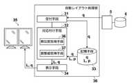
図2は、読影医用ワークステーション3に実装された本発明の実施形態となる自動レイアウト装置の構成とデータの流れを模式的に示したブロック図である。なお、本発明の自動レイアウト装置は読影医用ワークステーション3の自動レイアウト処理部として以下説明する。図2に示したように、本発明の自動レイアウト処理部30は、受付手段31、対応付け手段32、記憶手段33、および、表示手段34から構成される。また、表示手段34には、1台または複数台のディスプレイ35が接続される。 FIG. 2 is a block diagram schematically showing a configuration and a data flow of an automatic layout device according to an embodiment of the present invention mounted on a
受付手段31は、読影医用ワークステーション3で、読影医などのユーザによって検査対象の患者IDが入力されると、読影医用ワークステーション3から画像管理サーバ5に診断対象の患者IDと画像の送信要求が送信され、画像データベース6から検索された複数の検査画像qを検査データとして受信する。受信した検査画像qは、記憶手段33に一旦記憶される。
検査画像qには、様々なモダリティ2で撮影した画像が含まれ、単純X線撮影画像、同じ部位を撮影した現在画像および過去画像、造影剤の投与前後の画像、複数枚の断層画像(CT画像またはMRI画像など)、撮影条件を変えて撮影した画像(MRI画像のT1強調およびT2強調など)、および、内視鏡で撮影された動画像などが含まれる。さらに、アーカイブシステム10から検査依頼または検査情報を文書化した電子文書を受信し、これらの電子文書をイメージデータに変換したもの(例えば、PDFファイル)が検査画像に含まれていてもよい。The reception means 31 is the image
The inspection image q includes images taken with
記憶手段33は、複数の見本画像pと、見本画像pを画面上に配置したレイアウトを表すレイアウト情報Lを記憶している。なお、見本画像pは、検査画像を配置するとき見本となる画像であり、検査画像を配置する際の基準となる画像である。
レイアウト情報Lには、画面に画像を配置する際の画面の分割方法の情報と、分割されたそれぞれの領域にどの見本画像pを配置するかの配置位置の情報が定義されている。画面分割方法の情報には、分割された各表示領域の大きさも含まれ、例えば、画面を左右同じ大きさで縦2分割にする、画面を縦横に同じ大きさの4分割にする、あるいは、メイン画像を大きく画面の左半分に表示し、かつ、残りの画像を右半分に縦に並べるなどの情報が定義されている。The storage means 33 stores a plurality of sample images p and layout information L representing a layout in which the sample images p are arranged on the screen. The sample image p is an image that serves as a sample when arranging the inspection image, and is an image that serves as a reference when arranging the inspection image.
The layout information L defines information on a screen division method when arranging an image on the screen and information on an arrangement position of which sample image p is arranged in each of the divided areas. The information on the screen division method also includes the size of each divided display area. For example, the screen is divided into two vertically with the same size on the left and right, the screen is divided into four with the same size vertically and horizontally, or Information such as displaying the main image on the left half of the screen and arranging the remaining images vertically on the right half is defined.
レイアウトは、1画面のみであっても、複数の画面で構成されたものであってもよい。例えば、レイアウトが複数ページで構成され、見本画像pが配置された複数ページを切り替えながら表示画面に表示するときの画面分割方法と見本画像pの配置位置をレイアウト情報Lとして定義したものであってもよい。あるいは、レイアウト情報Lは、読影医用ワークステーション3に複数のディスプレイを接続したときの、複数のディスプレイの画面のそれぞれの画面分割方法と見本画像pの配置位置が定義されたものであってもよい。例えば、1台のディスプレイで、あるページの画面分割方法と分割された各領域に配置された見本画像pと、その次のページの画面分割方法と分割された各領域に配置された見本画像pの組合せを1つのレイアウト情報Lとしてもよく、また、ディスプレイが複数台あって、ディスプレイAは画面4分割とし、分割された各領域に見本画像pのどれを配置し、ディスプレイBは画面2分割とし、分割された各領域に見本画像pのどれを配置するかという情報を、1つのレイアウト情報Lとしてもよい。さらには、複数ディスプレイで複数枚のページの表示画面を切り替えて表示するときの画面分割方法と分割された各領域に配置された見本画像pの情報を1つのレイアウト情報Lとしてもよい。 The layout may have only one screen or may be composed of a plurality of screens. For example, the layout is composed of a plurality of pages, and the screen division method and the arrangement position of the sample image p when displaying on the display screen while switching the plurality of pages on which the sample image p is arranged are defined as the layout information L. May be good. Alternatively, the layout information L may define a screen division method for each of the screens of the plurality of displays and an arrangement position of the sample image p when a plurality of displays are connected to the
記憶手段33には、標準的な見本画像pと、標準的な画像分割方法と見本画像pの標準的な配置位置が定義されたレイアウト情報Lを予め用意して記憶しておいてもよいし、読影医用ワークステーション3で読影医が読影する際に、画像データベース6から読み込んだ画像をディスプレイの画面上に並べた時の画面分割方法と画像の配置位置の情報を記録したものをレイアウト情報Lとし、その時に並べた画像を見本画像pとして記憶するようにしてもよい。さらに、記憶手段33に記憶されているレイアウト情報Lを利用して検査画像qを表示し、読影医の好みに応じて、画像の配置位置や画面分割方法を変えた時のレイアウトに従って、レイアウト情報Lと見本画像pを更新してもよい。 The storage means 33 may prepare and store in advance the standard sample image p and the layout information L in which the standard image division method and the standard arrangement position of the sample image p are defined. Layout information L records the screen division method and image placement position information when the images read from the
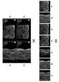
図3(a)にレイアウト情報Lに従って見本画像pを配置したレイアウトの一例を示す。図3(b)にレイアウトの各領域に配置される見本画像p1〜p7を示す。図3(a)は画面を4分割して、左上に見本画像p1を配置し、左下に見本画像p2を配置し、右上に見本画像p4を配置し、右下に見本画像p5を配置している。図3(a)において、見本画像p3、p6、およびp7は画面上に表示されていないが、次のページに見本画像p3、p6、およびp7を配置してもよい。 FIG. 3A shows an example of a layout in which the sample image p is arranged according to the layout information L. FIG. 3B shows sample images p1 to p7 arranged in each area of the layout. In FIG. 3A, the screen is divided into four, the sample image p1 is arranged in the upper left, the sample image p2 is arranged in the lower left, the sample image p4 is arranged in the upper right, and the sample image p5 is arranged in the lower right. There is. In FIG. 3A, the sample images p3, p6, and p7 are not displayed on the screen, but the sample images p3, p6, and p7 may be arranged on the next page.
このようなレイアウト情報Lは、読影医用ワークステーション3から画像管理サーバ5に送信されて画像データベース6に見本画像pと対応付けて記憶するようにしてよい。読影医用ワークステーション3で読影のための操作が行われると、画像管理サーバ5にレイアウト情報Lと見本画像pの送信を要求し、送信されたレイアウト情報Lと見本画像pを記憶手段33に記憶するようにしてもよい。記憶手段33には、レイアウト情報Lおよび見本画像pの組合せを予め複数の種類記憶しておき、複数の種類のレイアウト情報Lから症例や読影医の好みに応じて選択できるようにしておくのが好ましい。 Such layout information L may be transmitted from the image interpretation
対応付け手段32は、類似度取得手段36と、調整値取得手段37とを備え、レイアウトを構成する見本画像pに類似する検査画像qを検査データの中から選んで対応付ける。見本画像pと検査画像qを対応付ける際には、1つの見本画像pに対して2つ以上の検査画像qが対応付けられないようにする。なお、検査データに含まれる検査画像qの数がレイアウトに配置されている見本画像pの数より少ない場合には、見本画像pに対応付けられる検査画像qが存在しないこともある。また、2つ以上の見本画像pに同じ検査画像qが対応付けられないようにもする。つまり、見本画像pに対応付けられる検査画像qは1つ以下になり、かつ、検査データに含まれる検査画像qに対応付けられる見本画像pも1つ以下になるように対応付ける。 The associating means 32 includes the similarity acquisition means 36 and the adjustment value acquisition means 37, and selects and associates an inspection image q similar to the sample image p constituting the layout from the inspection data. When associating the sample image p with the inspection image q, two or more inspection images q are not associated with one sample image p. If the number of inspection images q included in the inspection data is less than the number of sample images p arranged in the layout, the inspection image q associated with the sample image p may not exist. Further, the same inspection image q is not associated with two or more sample images p. That is, the number of inspection images q associated with the sample image p is one or less, and the number of sample images p associated with the inspection image q included in the inspection data is also one or less.
類似度取得手段36は、レイアウトに含まれる見本画像pの1つと検査データに含まれる検査画像qの1つの組合せのそれぞれについて類似度を算出する。類似度は、見本画像pと検査画像qのピクセルデータ間の類似度を求める。ピクセルデータは、画像を構成する画素(ピクセル)の集まりをいう。具体的には、類似度は相互相関やヒストグラムインターセクションなどを用いて取得することができる。なお、画像のピクセルデータは、DICOMタグ、ファイル名、または、撮影日時などの画像の付帯情報とは区別して以下説明する。 The similarity acquisition means 36 calculates the similarity for each combination of one of the sample images p included in the layout and one of the inspection images q included in the inspection data. For the similarity, the similarity between the pixel data of the sample image p and the inspection image q is obtained. Pixel data refers to a collection of pixels that make up an image. Specifically, the similarity can be obtained by using cross-correlation, histogram intersection, or the like. The pixel data of the image will be described below separately from the DICOM tag, the file name, or the incidental information of the image such as the shooting date and time.
しかし、アキシャル断面とサジタル断面のように異なる断面方向の見本画像pと検査画像q間でも、ピクセルデータ間の類似度が高くなる場合がある。DICOMタグなどの付帯情報を参照して断面方向を判定し、レイアウトの見本画像pに含まれる断層画像と、検査データの検査画像qに含まれる断層画像の断面方向が一致する場合は、類似度は高くなり、断面方向が一致しない場合は、類似度は低くなるように類似度を算出する。 However, the similarity between the pixel data may be high even between the sample image p and the inspection image q in different cross-sectional directions such as the axial cross section and the sagittal cross section. The cross-sectional direction is determined by referring to the incidental information such as the DICOM tag, and if the cross-sectional direction of the tomographic image included in the layout sample image p and the tomographic image included in the inspection image q of the inspection data match, the degree of similarity Is high, and if the cross-sectional directions do not match, the similarity is calculated so that the similarity is low.
調整値取得手段37は、組合せの2つの組み合わせにおいて、第1の組合せaに含まれる見本画像pと第2の組合せbに含まれる見本画像pの関係と、第1の組合せaに含まれる検査画像qと第2の組合せbに含まれる検査画像qの関係とに基づいて類似度の調整値を求める。
同じ部位を撮影した造影剤の投与前と投与後の画像は、見本画像pと検査画像qの間でも投与前の画像同士と投与後の画像同士の類似度が高くなるはずだが、画像造影剤の拡散の仕方によっては投与前の見本画像pと投与後の検査画像qの類似度が高くなる可能性がある。また、心臓の心拍フェーズの異なる複数の画像など、ピクセルデータの類似度だけでは、対応する画像を判定することが難しくなることがある。そこで、組合せaおよびbに含まれる2つの見本画像pの撮影時刻の前後関係と、組合せaおよびbにそれぞれ含まれる2つの検査画像qの撮影時刻の前後関係が一致する場合には、調整値を撮影時刻の前後関係が一致しない場合より類似度が高くなるような値にする。The adjustment value acquisition means 37 has a relationship between the sample image p included in the first combination a and the sample image p included in the second combination b and the inspection included in the first combination a in the two combinations. The adjustment value of the similarity is obtained based on the relationship between the image q and the inspection image q included in the second combination b.
The images of the same site before and after administration of the contrast medium should have a high degree of similarity between the images before administration and the images after administration even between the sample image p and the inspection image q. Depending on the method of diffusion, the similarity between the sample image p before administration and the inspection image q after administration may increase. In addition, it may be difficult to determine the corresponding image only by the similarity of the pixel data, such as a plurality of images having different heartbeat phases of the heart. Therefore, if the context of the shooting times of the two sample images p included in the combinations a and b and the context of the shooting times of the two inspection images q included in the combinations a and b match, the adjustment value is adjusted. Set to a value so that the degree of similarity is higher than when the context of the shooting time does not match.
あるいは、見本画像pと検査画像qに複数の断層画像が含まれる場合には、断層画像の並び順が入れ替わらないようにする。例えば、アキシャル画像であるときは、組合せaおよびbに含まれる2つの見本画像pの断層位置の体軸方向の位置の前後関係と、組合せaおよびbに含まれる2つの検査画像qの断層位置の前後関係が一致する場合には、調整値を断層位置の前後関係が一致しない場合より類似度が高くなるような値にする。 Alternatively, when a plurality of tomographic images are included in the sample image p and the inspection image q, the order of the tomographic images is not changed. For example, in the case of an axial image, the anteroposterior relationship of the tomographic positions of the two sample images p included in the combinations a and b in the body axis direction and the tomographic positions of the two inspection images q included in the combinations a and b. When the contexts of the faults match, the adjustment value is set so that the similarity is higher than when the fault positions do not match.
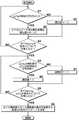
図4のフローチャートに従って、類似度と調整値を用いて見本画像pと検査画像qの対応付けを行う処理について具体的に説明する。図5に見本画像p1〜p7と検査画像q1〜q7の一例を示す。 A process of associating the sample image p with the inspection image q using the similarity and the adjustment value will be specifically described with reference to the flowchart of FIG. FIG. 5 shows an example of sample images p1 to p7 and inspection images q1 to q7.
まず、レイアウトに含まれる見本画像pの集合をP、検査データに含まれる検査画像qの集合をQとする。類似度取得手段36は、Pの要素である見本画像piとQの要素である検査画像qjの類似度をヒストグラムインターセクションを用いて求める。図5に示すように、類似度は、見本画像p1〜p7と検査画像q1〜q7の全ての組合せに対して求める。つまり、p1に対して、q1、q2、q3・・・q7との類似度を求め、p2に対してq1、q2、q3・・・q7との類似度を求める。同様にして、p3〜p7のそれぞれに対してq1、q2、q3・・・q7との類似度を求める。First, let P be the set of sample images p included in the layout, and let Q be the set of inspection images q included in the inspection data. Similarity
見本画像piおよび検査画像qjの断面方向は、例えば、DICOMタグの「Image Orientation」の記述に基づいて判断することができる。例えば、見本画像piが体軸に垂直なアキシャル断面の場合、「Image Orientation」の「first row」は(1,0,0)、「first column」は(0,1,0)にほぼ一致するので、検査画像qjの「Image Orientation」を参照して得られる2つのベクトルと、見本画像piの2つのベクトル(1,0,0)および(0,1,0)との一致度を、内積演算を使って求める。見本画像piと検査画像qjの断面方向が一致している場合には(S1−Yes)、ピクセルデータ間の類似度は、ヒストグラムインターセクションを類似度θaとして求める(S2)。The cross-sectional direction of the sample images pi and the inspection image qj, for example, can be determined based on the description of the "Image Orientation" of DICOM tags. For example, if the sample image pi is perpendicular axial plane to the body axis, "first row" of the "Image Orientation" is (1,0,0), "first column" are substantially equal to (0,1,0) to so, the degree of coincidence of the two vectors obtained by referring to the "image Orientation" of the inspection image qj, two vectors (1, 0, 0) and the sample image pi and (0,1,0) Is calculated using the inner product operation. If the cross-sectional direction of the sample image pi and the inspection image qj matches (S1-Yes), the similarity between the pixel data, a histogram intersection as the similarity θa (S2).
図6に示すように、ヒストグラムインターセクションは、見本画像piのヒストグラムh1と検査画像qjのヒストグラムh2の共通部分の割合を指す。このとき、類似度θaは0〜1.0までの値となる。画面のおおまかな構図を反映させるために、例えば、見本画像piと検査画像qjを縦と横をそれぞれ3つに等分し(図7参照)、3×3区画(=9区画)に区分したそれぞれの区画でヒストグラムインターセクションを求め、その平均値を類似度θaとするようにしてもよい(S1−No)。一方、見本画像piと検査画像qjの断面方向が異なる場合には、類似度θaを−1とする(S3)。これを全てのpiとqjの組合せについて求める(S4)。As shown in FIG. 6, histogram intersection, refers to the ratio of the common portion of the histogram h2 of sample images pi histogram h1 and inspection image qj of. At this time, the similarity θa is a value from 0 to 1.0. To reflect the approximate composition of the screen, for example, (see FIG. 7) equal portions inspection image qj and sample image pi vertically and horizontally into three respectively, the 3 × 3 compartments (= 9 sections) A histogram intersection may be obtained in each of the divided sections, and the average value thereofmay be set to the similarity θ a (S1-No). On the other hand, if the cross-sectional direction of the sample imagep i and the inspection imageq j are different, and -1 similarity θa (S3). This determined for all combinations ofp i andq j (S4).
次に、調整値取得手段37で、見本画像piと検査画像qjを対応付けた時の類似度の調整値θabを求める。見本画像piと検査画像qjを対応付けるときは、見本画像piに対応付けられる検査画像qjは1つ以下になり、かつ、検査データに含まれる検査画像qjに対応付けられる見本画像piも1つ以下になるように対応付ける。このような対応付けの条件を満足するように対応付けをした時の、全ての対応付けパターンのうちいずれの対応付けが最適であるかを、見本画像piと検査画像qjのピクセルデータ間の類似度θaだけでなく撮影時刻の前後関係に基づいた調整値を用いて調整する。Next, the adjustment value acquisition means 37 obtainsthe adjustment value θ ab of the degree of similarity when thesample image pi and the inspection image qj are associated with each other. When associating the inspection image qj and sample image pi, the inspection image qj associated with the sample image pi becomes less one, and sample image associated with the inspection image qj included in the inspection data pi is also associated at 1 or less. Between the pixel dataof the sample image pi and the inspection image qj , which of all the mapping patterns is optimal when the mapping is performed so as to satisfy the matching conditions. The adjustment is made using not only the similarity θa of the above but also the adjustment value based on the context of the shooting time.
集合Pと集合Qにおいて、見本画像piに検査画像qjを対応付け、かつ、見本画像pkに検査画像qlを対応付けたときには、見本画像piと検査画像qjの組合せaと見本画像pkと検査画像qlの組合せbから調整値θabを算出する。見本画像piの撮影時刻t(pi)と見本画像pkの撮影時刻t(pk)の差分Ta=t(pk)−t(pi)の符号と、検査画像qjの撮影時刻t(qj)と検査画像qlの撮影時刻t(ql)の差分Tb=t(ql)−t(qj)の符号が一致している場合には(S5−Yes)、調整値θabを1とし(S6)、差分Taと時間の差分Tbの符号が一致していない場合には(S5−No)、調整値θabを‐1にする(S7)。これを各対応付けパターンにおける全ての2つの組合せaおよびbに対して求める(S8)。In the set P and the set Q, when the sample image pi is associated with the inspection image qj and the sample image pk is associated with the inspection image ql , the combination a of the sample image pi and the inspection image qj is used.The adjustment value θ ab is calculated from the combination b of the sample image pk and the inspection image ql. And the sign of the differenceT a = t (p k) -t of the sample imagep i of shooting time t(p i) and the sample imagep k of shooting timet (p k) (p i ), of the inspection imageq j Difference between the shooting time t (qj ) and the shooting time t (ql ) of the inspection image ql Whenthe signs of T b = t (ql ) −t (qj ) match, (S5-Yes) ), the adjustment value thetaab and 1 (S6), if the sign of the differenceT b of the differenceT a and time does not match (S5-no), to -1 adjustment value thetaab (S7) .. This is obtained for all two combinations a and b in each association pattern (S8).
例えば、図8に示すように、p1とq1、p2とq2、p3とq3・・・を対応付けたとき、p1とq1の組合せ1とp2とq2の組合せ2において(図8(a))、p1とp2の撮影時刻の差分と、q1とq2の撮影時刻の差分が一致しているときには、調整値θa=1,b=2を1とする。p2とq2の組合せ2とp3とq3の組合せ3において(図8(b))、p2とp3の撮影時刻の差分と、q2とq3の撮影時刻の差分が一致していない場合には、調整値θa=2,b=3を‐1にする。さらに、p1とq1の組合せ1とp3とq3の組合せ3において(図8(c))、p1とp3の撮影時刻の差分と、q1とq3の撮影時刻の差分が一致しているときには、調整値θa=1,b=3を1とする。このように、全ての2つの組合せaおよびbに対して、調整値θabを算出する。For example, as shown in FIG. 8, when associated withp 1 andq 1,p 2 andq 2,p 3 andq 3 · · ·, thep 1 andq
図9に示すように、集合Pと集合Qにおける、見本画像piと検査画像qjの対応付けを0と1のバイナリデータxを用いてP×Qの要素の対応付行列mで表す。対応付行列mは、行が見本画像piを表し、列が検査画像qjを表す。i行j列の要素xijは見本画像piと検査画像qjを対応づけるか否かを表す。見本画像piと検査画像qjが対応付けられないときは0とし、見本画像piと検査画像qjが対応付けられるときは1とする。このとき、集合Pと集合Qにおいて、見本画像piに対応付けられる検査画像qjは高々1つ、かつ、検査画像qjに対応付けられる見本画像piも高々1つという条件を満足するように、見本画像piと検査画像qjを対応付けた全ての対応付けのパターンを作成する。
なお、対応付行列mで表される対応付けパターンの集合Mは次の式(1)のように表現することができる。
The set M of the association patterns represented by the associated matrix m can be expressed as in the following equation (1).
集合Mに含まれる見本画像piと検査画像qjを対応付ける全てのパターンにおいて、集合Pの見本画像piと集合Qの検査画像qj間の類似度が最も高くなるパターンを決定することで、見本画像piと検査画像qjの最適な対応付けを決定する(S9)。これは、類似度取得手段36で求めた類似度θaと、調整値取得手段37で求めた調整値θabを重みづけ加算した下式(2)を最大化する問題に置き換えることができる。例えば、文献「L. Torresani, V. Kolmogorov, and C. Rother: “Feature correspondence via graph matching: Models and global optimization”, ECCV2008.」に記載されているグラフマッチングの手法を用いて解くことができる。
なお、下式(2)の第1項は、xij=1となる見本画像piと検査画像qjの組合せの類似度θaの全てを加算することを意味し、第2項は、図8の対応付行列mにおいて、xij=1となる見本画像piと検査画像qjの組合せの2つ(組合せa、および、組合せb)の関係から得られた調整値θabの全てを重みづけ加算することを意味する。また、係数Kは経験的に最適な値を与えればよい。
ここで、
Aは、見本画像piと検査画像qjの組み合わせの集合を表す。
Nは、見本画像piと検査画像qjの組合せa、および、見本画像pkと検査画像qlの組合せbの集合を表す。
kは、類似度と調整値の荷重を決める係数を表す。
xaは、バイナリデータxのうち、組合せa(pi、qj)に対応する要素xijの値を表す。
xbは、バイナリデータxのうち、組合せb(pk、ql)に対応する要素xklの値を表す。In all patterns for associating the sample image pi and the inspection image qj included in the set M, to determine the degree of similarity is the highest becomes patterns between the inspection image qj of the sample image pi the set Q of the set P , to determine the optimal mapping of the sample imagep i and the inspection imageq j (S9). This can be replaced with the problem of maximizing the following equation (2) in whichthe similarity θ a obtained by the similarity acquisition means 36 andthe adjustment value θ ab obtained by the adjustment value acquisition means 37 are weighted and added. For example, it can be solved by using the graph matching method described in the document "L. Torresani, V. Kolmogorov, and C. Rother:" Feature correspondence via graph matching: Models and global optimization ", ECCV 2008.".
The first term of the following equation (2) means that all of the similarity θaof the combination of the sample image pi and the inspection image qjfor which x ij = 1 is added, and the second term is In the associated matrix m of FIG. 8, all of theadjustment values θ ab obtained from the relationship between the combination of the sample imagepi and the inspection image qjwhere x ij = 1 (combination a and combination b). Means to weight and add. Further, the coefficient K may be given an empirically optimal value.
here,
A represents a set of combinations of the sample imagepi and the inspection image qj.
N represents a set of a combination a of the sample image pi and the inspection image qj and a combination b of the sample image pk and the inspection image ql.
k represents a coefficient that determines the degree of similarity and the load of the adjustment value.
xa represents the value of the element xij corresponding to the combination a (pi , qj) in the binary data x.
xb represents the value of the element xkl corresponding to the combination b (pk , ql) in the binary data x.
表示手段34は、レイアウト情報Lに従った画像分割方法で画面を分割し、分割された各領域に、対応付け手段32の対応付け結果に従って、見本画像pに対応付けられた検査画像qをその見本画像pが配置される配置位置(領域)に表示する。 The display means 34 divides the screen by an image division method according to the layout information L, and in each of the divided areas, an inspection image q associated with the sample image p is provided according to the association result of the association means 32. It is displayed at the arrangement position (area) where the sample image p is arranged.
次に、図10のフローチャートを用いて、本実施形態の自動レイアウト装置の動作について説明する。 Next, the operation of the automatic layout device of the present embodiment will be described with reference to the flowchart of FIG.
読影医によって読影医用ワークステーション3で読影のための操作が行われると(S10)、入力された読影医IDが読影医用ワークステーション3から画像管理サーバ5に送信され(S11)、読影医IDに応じたレイアウト情報Lと見本画像pが画像データベース6から送信され記憶手段33に記憶される(S12)。 When an operation for image interpretation is performed on the image
続いて、読影医が診断対象の患者IDを入力すると(S13)、読影医用ワークステーション3の受付手段31は、画像管理サーバ5に患者IDと検査画像qの送信要求を送信する。画像管理サーバ5は、患者IDが割り振られている検査画像qを画像データベース6から検索して読影医用ワークステーション3に送信する。受付手段31は受信した検査画像qを検査データとして記憶手段33に記憶する(S14)。 Subsequently, when the image interpreting doctor inputs the patient ID to be diagnosed (S13), the receiving means 31 of the image
上述で詳細に説明した対応付け手段32を用いて、記憶手段33に記憶されているレイアウト情報Lで用いられる見本画像pと検査画像qを対応付けた複数の対応付けパターンの集合を作成し、複数の対応付けパターンの中から全体の類似度が最も高くなる対応付けパターンを決定する(S15)。 Using the associating means 32 described in detail above, a set of a plurality of associating patterns in which the sample image p and the inspection image q used in the layout information L stored in the storage means 33 are associated with each other is created. Among the plurality of association patterns, the association pattern having the highest overall similarity is determined (S15).
表示手段34は、ディスプレイ35の画面をレイアウト情報Lの画面分割方法に従って分割し、対応付け手段32で決定された見本画像pと検査画像qの対応付けに従って、検査画像qを各検査画像qに対応付けられた見本画像pが配置されている領域に配置して表示する(S16)。 The display means 34 divides the screen of the
対応付け手段32によって、図11に示すように、図5の見本画像p1〜p7と検査画像q1〜q7が対応付けられた場合には、表示手段34によってディスプレイ画面上には図12のように表示される。The associating
以上の通り、画面上に配置される見本画像と類似した検査画像が配置され、さらに、見本画像の撮影時刻の順番と検査画像の撮影時刻の順番が反対にならないように並べられる。 As described above, the inspection images similar to the sample images arranged on the screen are arranged, and further, they are arranged so that the order of the shooting times of the sample images and the order of the shooting times of the inspection images are not reversed.
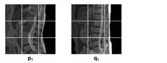
上述では、撮影時刻の順番が見本画像と検査画像の間で一致するように対応付けパターンを決定する場合について説明したが、レイアウトの見本画像に断層画像が含まれ、検査データの検査画像にも断層画像が含まれている場合に、断層画像の位置関係の順番が見本画像と検査画像の間で一致するように対応付けパターンを決定することもできる。 In the above, the case where the association pattern is determined so that the order of the shooting times matches between the sample image and the inspection image has been described. However, the sample image of the layout includes the tomographic image, and the inspection image of the inspection data also includes the tomographic image. When the tomographic image is included, the association pattern can be determined so that the order of the positional relationship of the tomographic image matches between the sample image and the inspection image.
この場合、類似度取得手段36は、前述と同様に類似度θaを求めるが、調整値取得手段37では、見本画像piと検査画像qjの組合せaと見本画像pkと検査画像qlの組合せbから調整値θabを算出するときに、見本画像piと見本画像pkの断層位置の差分D1の符号と、検査画像qjと検査画像qlの断層位置の差分D2の符号が一致している場合には、調整値θabを1とし、差分D1と差分D2の符号が一致していない場合には、調整値θabを‐1にして、類似度θaと調整値θabを加算した数式(2)を最大化することによって、見本画像piに検査画像qjの最適な組み合わせを決定することが可能になる。In this case, the
また、見本画像の断層画像の位置関係と検査画像の断層画像の位置関係についても矛盾することがないように並べることができる。
以上詳細に説明したように、従来は画像の付帯情報からは正確に判断できなかったレイアウトが、見本画像を参考にして、見本画像と検査画像の正確な対応付けを行うことが可能になる。In addition, the positional relationship of the tomographic images of the sample image and the positional relationship of the tomographic images of the inspection image can be arranged so as not to be inconsistent.
As described in detail above, the layout, which could not be accurately determined from the incidental information of the image in the past, can be accurately associated with the sample image and the inspection image with reference to the sample image.
1、1a〜1d 医療情報システム
2 モダリティ
3 読影医用ワークステーション
4 診療科用ワークステーション
5 画像管理サーバ
6 画像データベース
7 読影レポートサーバ
8 読影レポートデータベース
9 ネットワーク
10 アーカイブシステム
11 大容量記憶装置
30 自動レイアウト処理部
31 受付手段
32 対応付け手段
33 記憶手段
34 表示手段
35 ディスプレイ
36 類似度取得手段
37 調整値取得手段1, 1a to 1d
Claims (10)
Translated fromJapanese複数の見本画像を画面上に配置する際の各画像の大きさと配置位置が定められたレイアウトを表すレイアウト情報を記憶する記憶手段と、
前記レイアウトに含まれる各見本画像と、前記検査データに含まれる複数の各検査画像との間の類似度であり、前記レイアウトに含まれる見本画像の1つと前記検査データに含まれる検査画像の1つの組合せのそれぞれについて得られた類似度を用いて、前記レイアウトに含まれる各見本画像に前記検査データに含まれる検査画像を対応付けた複数の対応付けパターンのうちの、前記各対応付けパターンに含まれる前記組合せの全体の類似度が最大になる対応付けパターンに従って、前記レイアウトに含まれる各見本画像に類似する前記検査画像を対応付ける対応付け手段と、
前記見本画像に対応付けられた前記検査画像を、前記レイアウト情報に従って該検査画像が対応付けられた前記見本画像が配置される配置位置に表示する表示手段とを備え、
前記対応付けパターンは、前記見本画像に対応付けられる前記検査画像が1以下であり、かつ、前記検査画像に対応付けられる前記見本画像が1以下であるという条件を満たすように、前記見本画像と前記検査画像を対応付ける自動レイアウト装置。A reception means that accepts inspection data including multiple inspection images,
A storage means for storing layout information representing a layout in which the size and arrangement position of each image when arranging a plurality of sample images on the screen are defined, and
It is the degree of similarity between each sample image included in the layout and each of the plurality of inspection images included in the inspection data, and one of the sample images included in the layout and one of the inspection images included in the inspection data. Using the similarity obtained for each of the two combinations, each of theassociated patterns among the plurality of associated patterns in which the inspection image included in the inspection data is associated with each sample image included in the layout is used. A mapping means for associating the inspection images similar to each sample image included in the layoutaccording to a mapping pattern that maximizes the overall similarity of the included combinations.
The inspection image associated with the sample image is provided with a display means for displaying the inspection image associated with the sample image at an arrangement position where the sample image associated with the inspection image is arranged according to the layout information.
The association pattern with the sample image so as to satisfy the condition that the inspection image associated with the sample image is 1 or less and the sample image associated with the inspection image is 1 or less. An automatic layout devicethat associates the inspection images.
前記検査データの検査画像には断層画像が含まれ、
前記対応付け手段が、前記組合せのうち前記見本画像の断層画像と前記検査画像の断層画像の断面方向が異なる組合せには、断面方向が一致する組合せより類似度を低く設定して、全体の類似度が最大になる対応付けパターンを決定する請求項1または2記載の自動レイアウト装置。The sample image of the layout includes a tomographic image,
The inspection image of the inspection data includes a tomographic image,
Among the combinations, thecombination in which the tomographic image of the sample image and the tomographic image of the inspection image have different cross-sectional directions is set to have a lower degree of similarity than the combination having the same cross-sectional direction, and the matching means is similar as a whole. The automatic layout device according to claim 1 or 2, wherein the association pattern that maximizes the degree is determined.
前記組合せのそれぞれについて、前記検査画像と前記見本画像の類似度を取得する類似度取得手段と、
2つの前記組合せにおいて、第1の組合せに含まれる見本画像と第2の組合せに含まれる見本画像の撮影時刻の前後関係と、前記第1の組合せに含まれる検査画像と前記第2の組合せに含まれる検査画像の撮影時刻の前後関係とに基づいて、前記第1の組合せに含まれる見本画像と前記第2の組合せに含まれる見本画像の撮影時刻の順番と前記第1の組合せに含まれる検査画像と前記第2の組合せに含まれる検査画像の撮影時刻の順番とが一致する場合には、前記撮影時刻の順番が一致しない場合より前記全体の類似度を高くする調整値を取得する調整値取得手段とを備え、
前記対応付け手段が、前記各対応付けパターンの類似度を、前記対応付けられた前記見本画像と前記検査画像の組合せにおける前記類似度取得手段によって取得された全ての前記類似度と、2つの前記組合せにおける前記調整値取得手段によって取得された全ての前記調整値とを用いて取得し、前記見本画像と前記検査画像を対応付ける請求項1記載の自動レイアウト装置。The associative means
For each of the combinations, a similarity acquisition means for acquiring the similarity between the inspection image and the sample image, and
In the two combinations, the context of the shooting time of the sample image included in the first combination and the sample image included in the second combination, and the inspection image included in the first combination and the second combination Based on the context of the shooting time of the included inspection image, thesample image included in the first combination and the sample image included in the second combination are included in the shooting time order and the first combination. When the order of the shooting times of the inspection image and the inspection image included in the second combination match, the adjustment for acquiring the adjustment value for increasing the similarity of the whole as compared with the case where the order of the shooting times does not match. Equipped with value acquisition means
The associating means sets the similarity of each associating pattern to all the similarity acquired by the similarity acquiring means in the combination of the associated sample image and the inspection image, and two of the above.obtained using all of the adjustment value acquired by the adjusted value acquiring means in combination, an automatic layout system according to claim1, wherein associating the inspection image and the sample image.
前記検査データの検査画像には断層画像が含まれ、
前記対応付け手段が、前記検査データに含まれる複数の検査画像の断層画像のうち、前記見本画像の断層画像と断面方向が一致する検査画像とを対応付ける請求項1〜6のいずれか1項記載の自動レイアウト装置。The sample image of the layout includes a tomographic image,
The inspection image of the inspection data includes a tomographic image,
The one according to any one ofclaims 1 to 6 , wherein the associating means associates the tomographic image of the sample image with the inspection image having the same cross-sectional direction among the tomographic images of the plurality of inspection images included in the inspection data. Automatic layout device.
前記検査データの検査画像には断層画像が含まれ、
前記対応付け手段が、
前記組合せのそれぞれについて、前記検査画像と前記見本画像の類似度を取得する類似度取得手段と、
2つの前記組合せにおいて、第1の組合せに含まれる見本画像と第2の組合せに含まれる見本画像の断層位置の前後関係と、前記第1の組合せに含まれる検査画像と前記第2の組合せに含まれる検査画像の断層位置の前後関係とに基づいて、前記第1の組合せに含まれる見本画像と前記第2の組合せに含まれる見本画像の断層位置の順番と前記第1の組合せに含まれる検査画像と前記第2の組合せに含まれる検査画像の断層位置の順番とが一致する場合には、前記断層位置の順番が一致しない場合より前記全体の類似度を高くする調整値を取得する調整値取得手段とを備え、
前記対応付け手段が、前記各対応付けパターンの全体の類似度を、前記対応付けられた前記見本画像と前記検査画像の組合せにおける前記類似度取得手段によって取得された全ての前記類似度と、2つの前記組合せにおける前記調整値取得手段によって取得された全ての前記調整値とを用いて取得し、前記見本画像と前記検査画像を対応付ける請求項1記載の自動レイアウト装置。The sample image of the layout includes a tomographic image,
The inspection image of the inspection data includes a tomographic image,
The associative means
For each of the combinations, a similarity acquisition means for acquiring the similarity between the inspection image and the sample image, and
In the two combinations, the anteroposterior relationship between the tomographic position of the sample image included in the first combination and the sample image included in the second combination, and the inspection image included in the first combination and the second combination Based on the context of the tomographic position of the included inspection image, the order of the tomographic position of thesample image included in the first combination and the sample image included in the second combination is included in the first combination. When the order of the tomographic positions of the inspection image and the inspection image included in the second combination match, the adjustment to obtain the adjustment value for increasing the similarity of the whole as compared with the case where the order of the tomographic positions does not match. Equipped with value acquisition means
The associating means sets the overall similarity of each associating pattern with all the similarity acquired by the similarity acquiring means in the combination of the associated sample image and the inspection image, and 2The automatic layout device according to claim 1, which is acquired by using all the adjustment values acquired by the adjustment value acquisition means in the combination, and associates the sample image with the inspection image.
前記受付手段が、複数の検査画像を含む検査データを受け付けるステップと、
前記対応付け手段が、前記レイアウトに含まれる各見本画像と、前記検査データに含まれる複数の各検査画像との間の類似度であり、前記レイアウトに含まれる見本画像の1つと前記検査データに含まれる検査画像の1つの組合せのそれぞれについて得られた類似度を用いて、前記レイアウトに含まれる各見本画像に前記検査データに含まれる検査画像を対応付けた複数の対応付けパターンのうちの、前記各対応付けパターンに含まれる前記組合せの全体の類似度が最大になる対応付けパターンに従って、前記レイアウトに含まれる各見本画像に類似する前記検査画像を対応付けるステップと、
前記表示手段が、前記見本画像に対応付けられた前記検査画像を、前記レイアウト情報に従って該検査画像が対応付けられた前記見本画像が配置される配置位置に表示するステップとを備え、
前記対応付けパターンは、前記見本画像に対応付けられる前記検査画像が1以下であり、かつ、前記検査画像に対応付けられる前記見本画像が1以下であるという条件を満たすように、前記見本画像と前記検査画像を対応付ける自動レイアウト方法。It is provided with a storage means for storing layout information representing a layout in which the size and placement position of each image when arranging a plurality of sample images on the screen are defined, a reception means, an association means, and a display means. In the automatic layout device
A step in which the receiving means receives inspection data including a plurality of inspection images, and
The associating means is the degree of similarity between each sample image included in the layout and each of the plurality of inspection images included in the inspection data, and one of the sample images included in the layout and the inspection data. Using the similarity obtained for each of the combinations of theincluded inspection images, among a plurality of association patterns in which the inspection images included in the inspection data are associated with each sample image included in the layout. A step of associating the inspection image similar to each sample image included in the layoutaccording to the association pattern that maximizes the overall similarity of the combination included in each association pattern.
The display means includes a step of displaying the inspection image associated with the sample image at an arrangement position where the sample image associated with the inspection image is arranged according to the layout information.
The association pattern with the sample image so as to satisfy the condition that the inspection image associated with the sample image is 1 or less and the sample image associated with the inspection image is 1 or less. An automatic layout methodfor associating the inspection images.
複数の検査画像を含む検査データを受け付ける受付手段と、
複数の見本画像を画面上に配置する際の各画像の大きさと配置位置が定められたレイアウトを表すレイアウト情報を記憶する記憶手段と、
前記レイアウトに含まれる各見本画像と、前記検査データに含まれる複数の各検査画像との間の類似度であり、前記レイアウトに含まれる見本画像の1つと前記検査データに含まれる検査画像の1つの組合せのそれぞれについて得られた類似度を用いて、前記レイアウトに含まれる各見本画像に前記検査データに含まれる検査画像を対応付けた複数の対応付けパターンのうちの、前記各対応付けパターンに含まれる前記組合せの全体の類似度が最大になる対応付けパターンに従って、前記レイアウトに含まれる各見本画像に類似する前記検査画像を対応付ける対応付け手段と、
前記見本画像に対応付けられた前記検査画像を、前記レイアウト情報に従って該検査画像が対応付けられた前記見本画像が配置される配置位置に表示する表示手段として機能させる自動レイアウトプログラムであって、
前記対応付けパターンは、前記見本画像に対応付けられる前記検査画像が1以下であり、かつ、前記検査画像に対応付けられる前記見本画像が1以下であるという条件を満たすように、前記見本画像と前記検査画像を対応付ける自動レイアウトプログラム。
Computer,
A reception means that accepts inspection data including multiple inspection images,
A storage means for storing layout information representing a layout in which the size and arrangement position of each image when arranging a plurality of sample images on the screen are defined, and
It is the degree of similarity between each sample image included in the layout and each of the plurality of inspection images included in the inspection data, and one of the sample images included in the layout and one of the inspection images included in the inspection data. Using the similarity obtained for each of the two combinations, each of theassociated patterns among the plurality of associated patterns in which the inspection image included in the inspection data is associated with each sample image included in the layout is used. A mapping means for associating the inspection images similar to each sample image included in the layoutaccording to a mapping pattern that maximizes the overall similarity of the included combinations.
It said inspection image associated with the sample image,an automatic layout program Ru to function as display means for displaying the position of the sample image the test image are associated with each other are arranged in accordance with the layoutinformation,
The association pattern with the sample image so as to satisfy the condition that the inspection image associated with the sample image is 1 or less and the sample image associated with the inspection image is 1 or less. automatic layout program Ruassociates the inspection image.
Applications Claiming Priority (2)
| Application Number | Priority Date | Filing Date | Title |
|---|---|---|---|
| US201762483492P | 2017-04-10 | 2017-04-10 | |
| US62/483,492 | 2017-04-10 |
Publications (2)
| Publication Number | Publication Date |
|---|---|
| JP2018175864A JP2018175864A (en) | 2018-11-15 |
| JP6885896B2true JP6885896B2 (en) | 2021-06-16 |
Family
ID=63711160
Family Applications (1)
| Application Number | Title | Priority Date | Filing Date |
|---|---|---|---|
| JP2018074188AActiveJP6885896B2 (en) | 2017-04-10 | 2018-04-06 | Automatic layout device and automatic layout method and automatic layout program |
Country Status (2)
| Country | Link |
|---|---|
| US (1) | US10950019B2 (en) |
| JP (1) | JP6885896B2 (en) |
Families Citing this family (7)
| Publication number | Priority date | Publication date | Assignee | Title |
|---|---|---|---|---|
| US10936778B2 (en)* | 2016-03-28 | 2021-03-02 | Motivo, Inc. | And optimization of physical cell placement |
| JP6845071B2 (en) | 2017-04-12 | 2021-03-17 | 富士フイルム株式会社 | Automatic layout device and automatic layout method and automatic layout program |
| JP7163240B2 (en)* | 2019-04-11 | 2022-10-31 | 富士フイルム株式会社 | Display control device, display control device operating method, and display control device operating program |
| US12394511B2 (en)* | 2019-11-18 | 2025-08-19 | Fujifilm Healthcare Americas Corporation | Methods and systems for remote analysis of medical image records |
| JP7440317B2 (en)* | 2020-03-26 | 2024-02-28 | キヤノンメディカルシステムズ株式会社 | Medical information processing system, medical information processing device, and medical information processing program |
| WO2022054373A1 (en)* | 2020-09-14 | 2022-03-17 | 富士フイルム株式会社 | Medical image device and method for operating same |
| CN112508302B (en)* | 2020-12-22 | 2023-08-15 | 常州信息职业技术学院 | Quick layout method |
Family Cites Families (244)
| Publication number | Priority date | Publication date | Assignee | Title |
|---|---|---|---|---|
| JP3512992B2 (en)* | 1997-01-07 | 2004-03-31 | 株式会社東芝 | Image processing apparatus and image processing method |
| US6928314B1 (en)* | 1998-01-23 | 2005-08-09 | Mayo Foundation For Medical Education And Research | System for two-dimensional and three-dimensional imaging of tubular structures in the human body |
| JP4260938B2 (en)* | 1998-10-23 | 2009-04-30 | 株式会社東芝 | 3D ultrasonic diagnostic equipment |
| US7075683B1 (en)* | 1999-02-15 | 2006-07-11 | Canon Kabushiki Kaisha | Dynamic image digest automatic editing system and dynamic image digest automatic editing method |
| AU6634800A (en)* | 1999-08-11 | 2001-03-05 | Case Western Reserve University | Method and apparatus for producing an implant |
| US9208558B2 (en)* | 1999-08-11 | 2015-12-08 | Osteoplastics Llc | Methods and systems for producing an implant |
| US8781557B2 (en)* | 1999-08-11 | 2014-07-15 | Osteoplastics, Llc | Producing a three dimensional model of an implant |
| JP4702971B2 (en)* | 1999-11-10 | 2011-06-15 | 株式会社東芝 | Computer-aided diagnosis system |
| JP2002010056A (en)* | 2000-06-19 | 2002-01-11 | Fuji Photo Film Co Ltd | Image composing device |
| US20130211238A1 (en)* | 2001-01-30 | 2013-08-15 | R. Christopher deCharms | Methods for physiological monitoring, training, exercise and regulation |
| US20020103429A1 (en)* | 2001-01-30 | 2002-08-01 | Decharms R. Christopher | Methods for physiological monitoring, training, exercise and regulation |
| US7130457B2 (en)* | 2001-07-17 | 2006-10-31 | Accuimage Diagnostics Corp. | Systems and graphical user interface for analyzing body images |
| US6901277B2 (en)* | 2001-07-17 | 2005-05-31 | Accuimage Diagnostics Corp. | Methods for generating a lung report |
| US20040013302A1 (en)* | 2001-12-04 | 2004-01-22 | Yue Ma | Document classification and labeling using layout graph matching |
| AU2003216295A1 (en)* | 2002-02-15 | 2003-09-09 | The Regents Of The University Of Michigan | Lung nodule detection and classification |
| JP2004160103A (en)* | 2002-11-11 | 2004-06-10 | Terarikon Inc | Medical image compound observation apparatus |
| JP2004171361A (en)* | 2002-11-21 | 2004-06-17 | Canon Inc | Image display method, image display device, program, and storage medium |
| US7616801B2 (en)* | 2002-11-27 | 2009-11-10 | Hologic, Inc. | Image handling and display in x-ray mammography and tomosynthesis |
| JP4419426B2 (en)* | 2003-04-24 | 2010-02-24 | コニカミノルタエムジー株式会社 | Medical imaging system |
| US7570791B2 (en)* | 2003-04-25 | 2009-08-04 | Medtronic Navigation, Inc. | Method and apparatus for performing 2D to 3D registration |
| US20050152588A1 (en)* | 2003-10-28 | 2005-07-14 | University Of Chicago | Method for virtual endoscopic visualization of the colon by shape-scale signatures, centerlining, and computerized detection of masses |
| JP4069855B2 (en)* | 2003-11-27 | 2008-04-02 | ソニー株式会社 | Image processing apparatus and method |
| US7450743B2 (en) | 2004-01-21 | 2008-11-11 | Siemens Medical Solutions Usa, Inc. | Method and system of affine registration of inter-operative two dimensional images and pre-operative three dimensional images |
| JP2006024056A (en)* | 2004-07-09 | 2006-01-26 | Sony Corp | Driving method of printer, program of printer driver, and recording medium recording program of printer driver |
| US7787672B2 (en)* | 2004-11-04 | 2010-08-31 | Dr Systems, Inc. | Systems and methods for matching, naming, and displaying medical images |
| JP4800104B2 (en)* | 2005-06-13 | 2011-10-26 | 富士フイルム株式会社 | Album creating apparatus, album creating method, and program |
| JP4762731B2 (en)* | 2005-10-18 | 2011-08-31 | 富士フイルム株式会社 | Album creating apparatus, album creating method, and album creating program |
| WO2007058997A2 (en)* | 2005-11-11 | 2007-05-24 | The University Of Houston System | Scoring method for imaging-based detection of vulnerable patients |
| US7979790B2 (en)* | 2006-02-28 | 2011-07-12 | Microsoft Corporation | Combining and displaying multimedia content |
| JP2007260061A (en) | 2006-03-28 | 2007-10-11 | Fujifilm Corp | Medical image information processing apparatus, medical image storage system, and medical image confirmation work support program |
| US8639028B2 (en)* | 2006-03-30 | 2014-01-28 | Adobe Systems Incorporated | Automatic stacking based on time proximity and visual similarity |
| JP4874701B2 (en)* | 2006-04-18 | 2012-02-15 | 富士フイルム株式会社 | Similar image retrieval apparatus and method, and program |
| JP2007287018A (en)* | 2006-04-19 | 2007-11-01 | Fujifilm Corp | Diagnosis support system |
| CN101460089B (en)* | 2006-06-05 | 2011-05-11 | 柯尼卡美能达医疗印刷器材株式会社 | Display processing device |
| US10387612B2 (en)* | 2006-06-14 | 2019-08-20 | Koninklijke Philips N.V. | Multi-modality medical image layout editor |
| US8280483B2 (en)* | 2006-06-14 | 2012-10-02 | Koninklijke Philips Electronics N.V. | Multi-modality medical image viewing |
| JP2008035328A (en)* | 2006-07-31 | 2008-02-14 | Fujifilm Corp | Template generating device, image layout device, modified template generating device and program thereof |
| JP4762827B2 (en)* | 2006-08-22 | 2011-08-31 | 富士フイルム株式会社 | Electronic album generation apparatus, electronic album generation method, and program thereof |
| US8160676B2 (en)* | 2006-09-08 | 2012-04-17 | Medtronic, Inc. | Method for planning a surgical procedure |
| EP1916538A3 (en)* | 2006-10-27 | 2011-02-16 | Panasonic Electric Works Co., Ltd. | Target moving object tracking device |
| EP2081494B1 (en)* | 2006-11-16 | 2018-07-11 | Vanderbilt University | System and method of compensating for organ deformation |
| JP4905967B2 (en)* | 2007-03-02 | 2012-03-28 | 富士フイルム株式会社 | Similar case retrieval apparatus, method, and program |
| US8233965B2 (en)* | 2007-03-08 | 2012-07-31 | Oslo Universitetssykehus Hf | Tumor grading from blood volume maps |
| WO2008117827A1 (en)* | 2007-03-26 | 2008-10-02 | Nikon Corporation | Image display device, and program product for displaying image |
| US8081811B2 (en)* | 2007-04-12 | 2011-12-20 | Fujifilm Corporation | Method, apparatus, and program for judging image recognition results, and computer readable medium having the program stored therein |
| WO2008144751A1 (en)* | 2007-05-21 | 2008-11-27 | Cornell University | Method for segmenting objects in images |
| US20090002764A1 (en)* | 2007-06-27 | 2009-01-01 | Atkins C Brian | Arranging graphic objects on a page with relative area based control |
| US7889947B2 (en)* | 2007-06-27 | 2011-02-15 | Microsoft Corporation | Image completion |
| US20090082660A1 (en)* | 2007-09-20 | 2009-03-26 | Norbert Rahn | Clinical workflow for treatment of atrial fibrulation by ablation using 3d visualization of pulmonary vein antrum in 2d fluoroscopic images |
| WO2009049681A1 (en)* | 2007-10-19 | 2009-04-23 | Vascops | Automatic geometrical and mechanical analyzing method and system for tubular structures |
| WO2011065929A1 (en)* | 2007-11-23 | 2011-06-03 | Mercury Computer Systems, Inc. | Multi-user multi-gpu render server apparatus and methods |
| JP5025457B2 (en)* | 2007-12-28 | 2012-09-12 | キヤノン株式会社 | Image processing apparatus and method |
| US20090220135A1 (en) | 2008-02-28 | 2009-09-03 | Keigo Nakamura | System, server, method and program for image transfer |
| JP2009212969A (en)* | 2008-03-05 | 2009-09-17 | Toshiba Corp | Image processing apparatus, image processing method, and image processing program |
| JP5380283B2 (en)* | 2008-03-13 | 2014-01-08 | 株式会社東芝 | Template matching apparatus and method |
| JP5206095B2 (en)* | 2008-04-25 | 2013-06-12 | ソニー株式会社 | Composition determination apparatus, composition determination method, and program |
| JP5283088B2 (en)* | 2008-06-04 | 2013-09-04 | 国立大学法人静岡大学 | Image search device and computer program for image search applied to image search device |
| CA2727023C (en)* | 2008-06-06 | 2014-06-17 | Google Inc. | Annotating images |
| WO2010014712A1 (en)* | 2008-07-29 | 2010-02-04 | Board Of Trustees Of Michigan State University | System and method for differentiating benign from malignant contrast-enhanced lesions |
| JP5562598B2 (en)* | 2008-10-24 | 2014-07-30 | 株式会社東芝 | Image display apparatus, image display method, and magnetic resonance imaging apparatus |
| JP5523791B2 (en)* | 2008-10-27 | 2014-06-18 | 株式会社東芝 | X-ray diagnostic apparatus and image processing apparatus |
| US8004576B2 (en)* | 2008-10-31 | 2011-08-23 | Digimarc Corporation | Histogram methods and systems for object recognition |
| US8488863B2 (en)* | 2008-11-06 | 2013-07-16 | Los Alamos National Security, Llc | Combinational pixel-by-pixel and object-level classifying, segmenting, and agglomerating in performing quantitative image analysis that distinguishes between healthy non-cancerous and cancerous cell nuclei and delineates nuclear, cytoplasm, and stromal material objects from stained biological tissue materials |
| US8601385B2 (en)* | 2008-11-25 | 2013-12-03 | General Electric Company | Zero pixel travel systems and methods of use |
| US8682051B2 (en)* | 2008-11-26 | 2014-03-25 | General Electric Company | Smoothing of dynamic data sets |
| US20100135562A1 (en)* | 2008-11-28 | 2010-06-03 | Siemens Computer Aided Diagnosis Ltd. | Computer-aided detection with enhanced workflow |
| US20100157352A1 (en)* | 2008-12-19 | 2010-06-24 | Morales Javier A | Method and system for creating visual representation of wysiwyg finishing instructions for specialty photo media |
| US20100160765A1 (en)* | 2008-12-24 | 2010-06-24 | Marrouche Nassir F | Therapeutic success prediction for atrial fibrillation |
| JP2010176380A (en)* | 2009-01-29 | 2010-08-12 | Sony Corp | Information processing device and method, program, and recording medium |
| US9152292B2 (en)* | 2009-02-05 | 2015-10-06 | Hewlett-Packard Development Company, L.P. | Image collage authoring |
| JP5599572B2 (en)* | 2009-03-12 | 2014-10-01 | 富士フイルム株式会社 | Case image retrieval apparatus, method and program |
| WO2010109351A1 (en)* | 2009-03-26 | 2010-09-30 | Koninklijke Philips Electronics N.V. | A system that automatically retrieves report templates based on diagnostic information |
| JP5220677B2 (en)* | 2009-04-08 | 2013-06-26 | オリンパス株式会社 | Image processing apparatus, image processing method, and image processing program |
| JP5300585B2 (en)* | 2009-05-13 | 2013-09-25 | キヤノン株式会社 | Information processing apparatus and information processing method |
| CN102461152A (en)* | 2009-06-24 | 2012-05-16 | 惠普开发有限公司 | Compilation of images |
| JP5473429B2 (en)* | 2009-06-25 | 2014-04-16 | キヤノン株式会社 | Fundus imaging apparatus and control method thereof |
| US8867836B2 (en)* | 2009-09-01 | 2014-10-21 | Children's Medical Center Corporation | Image registration methods and apparatus using random projections |
| US8355556B2 (en)* | 2009-11-16 | 2013-01-15 | University Health Network | Method of synthetic image generation for magnetic resonance imaging |
| JP5580030B2 (en)* | 2009-12-16 | 2014-08-27 | 株式会社日立製作所 | Image processing apparatus and image alignment method |
| JP2011143159A (en)* | 2010-01-18 | 2011-07-28 | Toshiba Corp | Medical image display device, medical diagnostic system, and control program for image data display |
| EP2525978B1 (en)* | 2010-01-21 | 2018-04-11 | Hewlett-Packard Indigo B.V. | Automated inspection of a printed image |
| AU2011218194B2 (en)* | 2010-02-16 | 2015-12-10 | Duke University | Systems, methods, compositions and devices for in vivo magnetic resonance imaging of lungs using perfluorinated gas mixtures |
| JP5921068B2 (en)* | 2010-03-02 | 2016-05-24 | キヤノン株式会社 | Image processing apparatus, control method, and optical coherence tomography system |
| US9235575B1 (en)* | 2010-03-08 | 2016-01-12 | Hewlett-Packard Development Company, L.P. | Systems and methods using a slideshow generator |
| JP5152231B2 (en)* | 2010-03-12 | 2013-02-27 | オムロン株式会社 | Image processing method and image processing apparatus |
| CN102473307B (en)* | 2010-03-15 | 2015-05-27 | 松下电器产业株式会社 | Method and apparatus for trajectory estimation, and method for segmentation |
| US8774481B2 (en)* | 2010-03-25 | 2014-07-08 | Emory University | Atlas-assisted synthetic computed tomography using deformable image registration |
| US8988456B2 (en)* | 2010-03-25 | 2015-03-24 | Apple Inc. | Generating digital media presentation layouts dynamically based on image features |
| JP5572437B2 (en)* | 2010-03-29 | 2014-08-13 | 富士フイルム株式会社 | Apparatus and method for generating stereoscopic image based on three-dimensional medical image, and program |
| US8396268B2 (en)* | 2010-03-31 | 2013-03-12 | Isis Innovation Limited | System and method for image sequence processing |
| JP5458413B2 (en)* | 2010-05-14 | 2014-04-02 | 株式会社日立製作所 | Image processing apparatus, image processing method, and image processing program |
| WO2011156526A2 (en)* | 2010-06-08 | 2011-12-15 | Accuray, Inc. | Imaging methods and target tracking for image-guided radiation treatment |
| JP6039156B2 (en)* | 2010-06-08 | 2016-12-07 | キヤノン株式会社 | Image processing apparatus, image processing method, and program |
| US8422755B2 (en)* | 2010-06-11 | 2013-04-16 | Given Imaging Ltd. | System and method for synchronizing image sequences captured in-vivo for automatic comparison |
| US8750375B2 (en)* | 2010-06-19 | 2014-06-10 | International Business Machines Corporation | Echocardiogram view classification using edge filtered scale-invariant motion features |
| US9785653B2 (en)* | 2010-07-16 | 2017-10-10 | Shutterfly, Inc. | System and method for intelligently determining image capture times for image applications |
| US8870751B2 (en)* | 2010-09-28 | 2014-10-28 | Fujifilm Corporation | Endoscope system, endoscope image recording apparatus, endoscope image acquisition assisting method and computer readable medium |
| EP2453376B1 (en)* | 2010-11-15 | 2019-02-20 | Fujifilm Corporation | Medical image recording/reproducing apparatus, medical image recording/reproducing method and program |
| US9262444B2 (en)* | 2010-11-24 | 2016-02-16 | General Electric Company | Systems and methods for applying series level operations and comparing images using a thumbnail navigator |
| US9208556B2 (en)* | 2010-11-26 | 2015-12-08 | Quantitative Insights, Inc. | Method, system, software and medium for advanced intelligent image analysis and display of medical images and information |
| AU2010257231B2 (en)* | 2010-12-15 | 2014-03-06 | Canon Kabushiki Kaisha | Collaborative image capture |
| US20120206496A1 (en)* | 2011-02-11 | 2012-08-16 | Cok Ronald S | System for imaging product layout |
| US9014490B2 (en)* | 2011-02-15 | 2015-04-21 | Sony Corporation | Method to measure local image similarity and its application in image processing |
| CN102859985B (en)* | 2011-02-17 | 2015-08-05 | 松下电器(美国)知识产权公司 | Image evaluation apparatus, image evaluation method and integrated circuit |
| US10152951B2 (en)* | 2011-02-28 | 2018-12-11 | Varian Medical Systems International Ag | Method and system for interactive control of window/level parameters of multi-image displays |
| JP5820142B2 (en)* | 2011-04-27 | 2015-11-24 | キヤノン株式会社 | Information processing apparatus, control method therefor, and program |
| JP5526193B2 (en)* | 2011-06-20 | 2014-06-18 | 富士フイルム株式会社 | Image processing apparatus, image processing method, and image processing program |
| JP5449460B2 (en)* | 2011-06-28 | 2014-03-19 | 富士フイルム株式会社 | Image processing apparatus, image processing method, and image processing program |
| JP5462414B2 (en)* | 2011-06-30 | 2014-04-02 | パナソニック株式会社 | Similar case retrieval device, relevance degree database creation device, similar case retrieval method, and relevance degree database creation method |
| JP6023058B2 (en)* | 2011-08-29 | 2016-11-09 | パナソニック インテレクチュアル プロパティ コーポレーション オブ アメリカPanasonic Intellectual Property Corporation of America | Image processing apparatus, image processing method, program, integrated circuit |
| US9743839B2 (en)* | 2011-11-02 | 2017-08-29 | Seno Medical Instruments, Inc. | Playback mode in an optoacoustic imaging system |
| WO2013065090A1 (en)* | 2011-11-04 | 2013-05-10 | パナソニック株式会社 | Similar case retrieval device and similar case retrieval method |
| US9152760B2 (en)* | 2011-11-23 | 2015-10-06 | General Electric Company | Smart 3D PACS workflow by learning |
| US8923580B2 (en) | 2011-11-23 | 2014-12-30 | General Electric Company | Smart PACS workflow systems and methods driven by explicit learning from users |
| AU2013229748B2 (en)* | 2012-03-09 | 2017-11-02 | Seno Medical Instruments, Inc. | Statistical mapping in an optoacoustic imaging system |
| FI20125278A7 (en)* | 2012-03-14 | 2013-09-15 | Mirasys Business Analytics Oy | Method, arrangement and computer program product for recognizing videoed objects |
| JP5935501B2 (en)* | 2012-05-17 | 2016-06-15 | 富士通株式会社 | Program, image processing apparatus and image processing method |
| KR101446780B1 (en)* | 2012-06-01 | 2014-10-01 | 삼성메디슨 주식회사 | The method and apparatus for displaying an ultrasound image and an information related the image |
| JP6071289B2 (en)* | 2012-07-09 | 2017-02-01 | キヤノン株式会社 | Image processing apparatus, image processing method, and program |
| JP6071288B2 (en)* | 2012-07-09 | 2017-02-01 | キヤノン株式会社 | Image processing apparatus, image processing method, and program |
| JP6012309B2 (en)* | 2012-07-09 | 2016-10-25 | キヤノン株式会社 | Information processing apparatus, information processing method, and program |
| JP6025427B2 (en)* | 2012-07-09 | 2016-11-16 | キヤノン株式会社 | Image processing apparatus, image processing method, and program |
| JP6012310B2 (en)* | 2012-07-09 | 2016-10-25 | キヤノン株式会社 | Image processing apparatus, image processing method, and program |
| JP6012308B2 (en)* | 2012-07-09 | 2016-10-25 | キヤノン株式会社 | Image processing apparatus, image processing method, and program |
| JP6099931B2 (en)* | 2012-11-01 | 2017-03-22 | 株式会社東芝 | Image synchronization apparatus and system |
| US20140143710A1 (en)* | 2012-11-21 | 2014-05-22 | Qi Zhao | Systems and methods to capture and save criteria for changing a display configuration |
| JP5939141B2 (en)* | 2012-11-21 | 2016-06-22 | 富士ゼロックス株式会社 | Program and medical record retrieval device |
| US9372960B2 (en)* | 2012-12-11 | 2016-06-21 | ViewSend ICT Co., Ltd. | Medical support system and method thereof |
| JP6048107B2 (en)* | 2012-12-14 | 2016-12-21 | コニカミノルタ株式会社 | Electronic medical record apparatus and program |
| WO2014104129A1 (en)* | 2012-12-25 | 2014-07-03 | 株式会社 東芝 | Image observation device, image observation method, and computer-readable recording medium |
| US20150178786A1 (en)* | 2012-12-25 | 2015-06-25 | Catharina A.J. Claessens | Pictollage: Image-Based Contextual Advertising Through Programmatically Composed Collages |
| JP2014127011A (en)* | 2012-12-26 | 2014-07-07 | Sony Corp | Information processing apparatus, information processing method, and program |
| JP5847070B2 (en)* | 2012-12-27 | 2016-01-20 | オリンパス株式会社 | Server apparatus and photographing apparatus |
| US9177378B2 (en)* | 2013-02-11 | 2015-11-03 | Definiens Ag | Updating landmarks to improve coregistration as regions of interest are corrected |
| WO2014132754A1 (en)* | 2013-02-26 | 2014-09-04 | コニカミノルタ株式会社 | Image-processing device and image-processing method |
| US8976190B1 (en)* | 2013-03-15 | 2015-03-10 | Pme Ip Australia Pty Ltd | Method and system for rule based display of sets of images |
| US10070839B2 (en)* | 2013-03-15 | 2018-09-11 | PME IP Pty Ltd | Apparatus and system for rule based visualization of digital breast tomosynthesis and other volumetric images |
| US9600138B2 (en)* | 2013-03-15 | 2017-03-21 | Synaptive Medical (Barbados) Inc. | Planning, navigation and simulation systems and methods for minimally invasive therapy |
| JP6104680B2 (en)* | 2013-03-21 | 2017-03-29 | 株式会社日立国際電気 | Image processing apparatus, imaging apparatus, monitoring system, encoding apparatus, and image processing method |
| JP5948275B2 (en)* | 2013-03-29 | 2016-07-06 | 富士フイルム株式会社 | Radiographic apparatus, radiographic method, and radiographic control program |
| WO2014162740A1 (en)* | 2013-04-05 | 2014-10-09 | パナソニック株式会社 | Image region correlating device, three-dimensional model generating device, image region correlating method, and image region correlating program |
| KR102065362B1 (en)* | 2013-05-14 | 2020-01-13 | 삼성전자주식회사 | Apparatus and Method for extracting peak image in continuously photographed image |
| US20140376822A1 (en)* | 2013-06-25 | 2014-12-25 | Michael Holroyd | Method for Computing the Similarity of Image Sequences |
| JP5977214B2 (en)* | 2013-08-23 | 2016-08-24 | ジーイー・メディカル・システムズ・グローバル・テクノロジー・カンパニー・エルエルシー | Image processing method, apparatus, and program |
| US10169534B2 (en)* | 2013-09-30 | 2019-01-01 | Toshiba Medical Systems Corporation | Medical image display system and method |
| EP2863363A1 (en)* | 2013-09-30 | 2015-04-22 | Samsung Medison Co., Ltd. | Method and apparatus for generating three-dimensional image of target object |
| JP6462671B2 (en)* | 2013-10-03 | 2019-01-30 | ユニバーシティー オブ デラウェア | X slit camera |
| WO2015052094A1 (en)* | 2013-10-07 | 2015-04-16 | Agfa Graphics Nv | A raster image processing method |
| GB2523531A (en)* | 2013-11-29 | 2015-09-02 | Siemens Medical Solutions | Arrangements for viewing clinical images |
| US20150169207A1 (en)* | 2013-12-18 | 2015-06-18 | Dropbox, Inc. | Systems and methods for generating personalized account reconfiguration interfaces |
| US10083278B2 (en)* | 2014-02-12 | 2018-09-25 | Edda Technology, Inc. | Method and system for displaying a timing signal for surgical instrument insertion in surgical procedures |
| US9959631B2 (en)* | 2014-02-21 | 2018-05-01 | Samsung Electronics Co., Ltd. | Tomography apparatus and method for reconstructing tomography image thereof |
| US20150248429A1 (en)* | 2014-02-28 | 2015-09-03 | Microsoft Corporation | Generation of visual representations for electronic content items |
| US20150269456A1 (en)* | 2014-03-21 | 2015-09-24 | Bicdroid Inc | Methods and systems for determining a perceptual similarity between images |
| JP6054330B2 (en)* | 2014-03-27 | 2016-12-27 | 富士フイルム株式会社 | Image layout generation apparatus, image product generation system, image layout generation method, image layout generation program, and recording medium |
| JP5815167B1 (en)* | 2014-04-09 | 2015-11-17 | パナソニック株式会社 | Information terminal control method and program |
| WO2015155807A1 (en)* | 2014-04-09 | 2015-10-15 | パナソニック株式会社 | Information terminal control method and program |
| US9361700B2 (en)* | 2014-05-08 | 2016-06-07 | Tandent Vision Science, Inc. | Constraint relationship for use in an image segregation |
| JP6438216B2 (en)* | 2014-05-22 | 2018-12-12 | キヤノン株式会社 | Image generating apparatus and image generating method |
| JP6576690B2 (en)* | 2014-05-29 | 2019-09-18 | キヤノンメディカルシステムズ株式会社 | Medical image processing device |
| US9613181B2 (en)* | 2014-05-29 | 2017-04-04 | Globalfoundries Inc. | Semiconductor device structure including active region having an extension portion |
| US10216762B2 (en)* | 2014-06-04 | 2019-02-26 | Panasonic Corporation | Control method and non-transitory computer-readable recording medium for comparing medical images |
| CN105167793B (en)* | 2014-06-11 | 2018-10-09 | 佳能株式会社 | Image display device, display control device, and display control method |
| JP6035288B2 (en)* | 2014-07-16 | 2016-11-30 | 富士フイルム株式会社 | Image processing system, client, image processing method, program, and recording medium |
| JP6293619B2 (en)* | 2014-08-28 | 2018-03-14 | ジーイー・メディカル・システムズ・グローバル・テクノロジー・カンパニー・エルエルシー | Image processing method, apparatus, and program |
| US10748661B2 (en)* | 2014-10-30 | 2020-08-18 | Panasonic Corporation | Method for controlling information terminal, and recording medium |
| US9507506B2 (en)* | 2014-11-13 | 2016-11-29 | Interactive Memories, Inc. | Automatic target box in methods and systems for editing content-rich layouts in media-based projects |
| JP6548383B2 (en)* | 2014-11-28 | 2019-07-24 | キヤノンメディカルシステムズ株式会社 | Magnetic resonance imaging system |
| US9839490B2 (en)* | 2015-01-28 | 2017-12-12 | Terarecon, Inc. | Touchless advanced image processing and visualization |
| CN110338844B (en)* | 2015-02-16 | 2022-04-19 | 深圳迈瑞生物医疗电子股份有限公司 | Three-dimensional imaging data display processing method and three-dimensional ultrasonic imaging method and system |
| CN105912831B (en)* | 2015-02-19 | 2021-08-20 | 松下知识产权经营株式会社 | Control method of information terminal |
| JP6501569B2 (en)* | 2015-03-18 | 2019-04-17 | キヤノン株式会社 | IMAGE PROCESSING APPARATUS, IMAGE PROCESSING METHOD, AND PROGRAM |
| JP2016189507A (en)* | 2015-03-30 | 2016-11-04 | 富士フイルム株式会社 | Image processing device, image processing method, program and recording medium |
| JP2016189946A (en)* | 2015-03-31 | 2016-11-10 | 富士フイルム株式会社 | Medical image alignment apparatus and method, and program |
| US9767380B2 (en)* | 2015-04-13 | 2017-09-19 | Varian Medical Systems International Ag. | Image comparison tool tolerant to deformable image matching |
| US10178149B2 (en)* | 2015-05-14 | 2019-01-08 | Adobe Inc. | Analysis for framework assessment |
| WO2017002226A1 (en)* | 2015-07-01 | 2017-01-05 | 株式会社島津製作所 | Data processing device |
| KR20180128888A (en)* | 2015-07-24 | 2018-12-04 | 에테하 취리히 | Image processing system for downscaling an image using a perceptual downscaling method |
| US10242293B2 (en)* | 2015-08-04 | 2019-03-26 | The Asan Foundation | Method and program for computing bone age by deep neural network |
| JP6422409B2 (en)* | 2015-08-07 | 2018-11-14 | キヤノン株式会社 | Display control apparatus, display control method, and program |
| JP6494503B2 (en)* | 2015-08-07 | 2019-04-03 | キヤノン株式会社 | Image processing apparatus, image processing method, and program |
| JP6525862B2 (en)* | 2015-08-07 | 2019-06-05 | キヤノン株式会社 | Image processing apparatus, image processing method and program |
| JP6532398B2 (en)* | 2015-08-07 | 2019-06-19 | キヤノン株式会社 | Image processing apparatus, image processing method and program |
| JP6667231B2 (en)* | 2015-08-31 | 2020-03-18 | キヤノン株式会社 | Information processing apparatus, image processing apparatus, information processing system, information processing method, and program. |
| JP6677256B2 (en)* | 2015-09-02 | 2020-04-08 | 富士通株式会社 | Image interpretation support program, cross-sectional image generating device, and cross-sectional image generating method |
| CN105260733A (en)* | 2015-09-11 | 2016-01-20 | 北京百度网讯科技有限公司 | Method and device for processing image information |
| US9697623B1 (en)* | 2015-09-15 | 2017-07-04 | Shanghai United Imaging Healthcare Co., Ltd. | Image reconstruction system and method |
| US10771815B2 (en)* | 2015-09-29 | 2020-09-08 | Lg Electronics Inc. | Method and apparatus for processing video signals using coefficient induced prediction |
| JP6675099B2 (en)* | 2015-09-30 | 2020-04-01 | パナソニックIpマネジメント株式会社 | Control method and program |
| CN106560827B (en)* | 2015-09-30 | 2021-11-26 | 松下知识产权经营株式会社 | Control method |
| CN106557536B (en)* | 2015-09-30 | 2021-12-21 | 松下知识产权经营株式会社 | Control method |
| US10595941B2 (en)* | 2015-10-30 | 2020-03-24 | Orthosensor Inc. | Spine measurement system and method therefor |
| CN106845508B (en)* | 2015-12-07 | 2019-05-17 | 腾讯科技(深圳)有限公司 | The methods, devices and systems of release in a kind of detection image |
| KR102202398B1 (en)* | 2015-12-11 | 2021-01-13 | 삼성전자주식회사 | Image processing apparatus and image processing method thereof |
| WO2017109854A1 (en)* | 2015-12-22 | 2017-06-29 | オリンパス株式会社 | Learning image automatic sorting device, learning image automatic sorting method, and learning image automatic sorting program |
| JP6700791B2 (en)* | 2016-01-05 | 2020-05-27 | キヤノン株式会社 | Information processing apparatus, information processing method, and program |
| US10699156B2 (en)* | 2016-01-13 | 2020-06-30 | Peking University Shenzhen Graduate School | Method and a device for image matching |
| CN108780570B (en)* | 2016-01-16 | 2022-12-06 | 特利丹菲力尔有限责任公司 | Systems and methods for image super-resolution using iterative collaborative filtering |
| GB2547712A (en)* | 2016-02-29 | 2017-08-30 | Fujitsu Ltd | Method and apparatus for generating time series data sets for predictive analysis |
| US10902656B2 (en)* | 2016-02-29 | 2021-01-26 | Fujifilm North America Corporation | System and method for generating a digital image collage |
| JP6559609B2 (en)* | 2016-04-25 | 2019-08-14 | 富士フイルム株式会社 | Image composition apparatus, image composition method, and image composition program |
| AU2017278241B2 (en)* | 2016-06-06 | 2021-10-21 | iTomography Corp. | Systems and methods for automated sinogram completion, combination, and completion by combination |
| US10301041B2 (en)* | 2016-06-09 | 2019-05-28 | California Institute Of Technology | Systems and methods for tracking moving objects |
| WO2017223560A1 (en)* | 2016-06-24 | 2017-12-28 | Rensselaer Polytechnic Institute | Tomographic image reconstruction via machine learning |
| GB201611253D0 (en)* | 2016-06-29 | 2016-08-10 | Dolby Laboratories Licensing Corp | Efficient Histogram-based luma look matching |
| DE102016212888A1 (en)* | 2016-07-14 | 2018-01-18 | Siemens Healthcare Gmbh | Determine a series of images depending on a signature set |
| WO2018018160A1 (en)* | 2016-07-29 | 2018-02-01 | Novadaq Technologies ULC | Methods and systems for characterizing tissue of a subject utilizing machine learning |
| US20180070917A1 (en)* | 2016-09-13 | 2018-03-15 | Butterfly Network, Inc. | Ingestible ultrasound device, system and imaging method |
| JP2018050890A (en)* | 2016-09-28 | 2018-04-05 | 富士フイルム株式会社 | Image display apparatus, image display method, and program |
| US10445462B2 (en)* | 2016-10-12 | 2019-10-15 | Terarecon, Inc. | System and method for medical image interpretation |
| US10452813B2 (en)* | 2016-11-17 | 2019-10-22 | Terarecon, Inc. | Medical image identification and interpretation |
| US10109055B2 (en)* | 2016-11-21 | 2018-10-23 | Seiko Epson Corporation | Multiple hypotheses segmentation-guided 3D object detection and pose estimation |
| US10140675B2 (en)* | 2016-11-28 | 2018-11-27 | Google Llc | Image grid with selectively prominent images |
| JP6596406B2 (en)* | 2016-12-09 | 2019-10-23 | 富士フイルム株式会社 | Diagnosis support apparatus, operation method and operation program thereof, and diagnosis support system |
| WO2018114889A1 (en)* | 2016-12-22 | 2018-06-28 | Koninklijke Philips N.V. | A method and apparatus for positioning markers in images of an anatomical structure |
| CN109565601B (en)* | 2016-12-26 | 2020-10-23 | 华为技术有限公司 | A prediction method and device based on template matching |
| CN106682424A (en)* | 2016-12-28 | 2017-05-17 | 上海联影医疗科技有限公司 | Medical image adjusting method and medical image adjusting system |
| CN106682636B (en)* | 2016-12-31 | 2020-10-16 | 上海联影医疗科技有限公司 | Blood vessel extraction method and system |
| WO2018125812A1 (en)* | 2017-01-02 | 2018-07-05 | Gauss Surgical, Inc. | Tracking surgical items with prediction of duplicate imaging of items |
| JP6971598B2 (en)* | 2017-03-13 | 2021-11-24 | キヤノンメディカルシステムズ株式会社 | X-ray diagnostic equipment, image processing equipment and image processing program |
| JP6934734B2 (en)* | 2017-03-17 | 2021-09-15 | キヤノン株式会社 | Image processing device, control method and program of image processing device |
| EP3388962A1 (en)* | 2017-04-11 | 2018-10-17 | Siemens Healthcare GmbH | Control method of a medical imaging system |
| JP6845071B2 (en)* | 2017-04-12 | 2021-03-17 | 富士フイルム株式会社 | Automatic layout device and automatic layout method and automatic layout program |
| JP6949535B2 (en)* | 2017-04-13 | 2021-10-13 | キヤノン株式会社 | Information processing equipment, information processing system, information processing method and program |
| JP6869086B2 (en)* | 2017-04-20 | 2021-05-12 | 富士フイルム株式会社 | Alignment device, alignment method and alignment program |
| WO2018195501A2 (en)* | 2017-04-21 | 2018-10-25 | Cubisme, Inc. | System and method for creating, querying, and displaying a miba master file |
| EP3627442A4 (en)* | 2017-05-31 | 2020-05-20 | Shanghai United Imaging Healthcare Co., Ltd. | Method and system for image processing |
| WO2019023900A1 (en)* | 2017-07-31 | 2019-02-07 | 深圳联影医疗科技有限公司 | Method and system for extracting region of interest from volume data |
| CA3076181A1 (en)* | 2017-09-15 | 2019-03-21 | Saudi Arabian Oil Company | Inferring petrophysical properties of hydrocarbon reservoirs using a neural network |
| JP2019056623A (en)* | 2017-09-21 | 2019-04-11 | 株式会社東芝 | Image processing device, and image processing system |
| JP6810009B2 (en)* | 2017-09-29 | 2021-01-06 | トヨタ自動車株式会社 | Parallax calculator |
| JP7076974B2 (en)* | 2017-10-03 | 2022-05-30 | キヤノン株式会社 | Image processing equipment, control methods and programs |
| JP6807820B2 (en)* | 2017-10-31 | 2021-01-06 | 富士フイルム株式会社 | Image search device, method and program |
| JP2019091324A (en)* | 2017-11-16 | 2019-06-13 | コニカミノルタ株式会社 | Medical information processor and program |
| US10304564B1 (en)* | 2017-12-13 | 2019-05-28 | International Business Machines Corporation | Methods and systems for displaying an image |
| JP2019107084A (en)* | 2017-12-15 | 2019-07-04 | キヤノン株式会社 | Medical image apparatus and medical image display method |
| US11497459B2 (en)* | 2018-01-26 | 2022-11-15 | General Electric Company | Methods and system for optimizing an imaging scan based on a prior scan |
| JP6901424B2 (en)* | 2018-03-12 | 2021-07-14 | 株式会社東芝 | Image processing device and image processing method |
| JP2019154744A (en)* | 2018-03-13 | 2019-09-19 | キヤノンメディカルシステムズ株式会社 | Medical image processing device, medical image diagnostic device, and medical image processing program |
| JP6787358B2 (en)* | 2018-03-28 | 2020-11-18 | 京セラドキュメントソリューションズ株式会社 | Image forming device |
| US10462359B1 (en)* | 2018-04-13 | 2019-10-29 | Adobe Inc. | Image composition instruction based on reference image perspective |
| JP6938422B2 (en)* | 2018-04-23 | 2021-09-22 | キヤノン株式会社 | Image processing equipment, image processing methods, and programs |
| JP6981940B2 (en)* | 2018-08-29 | 2021-12-17 | 富士フイルム株式会社 | Diagnostic imaging support devices, methods and programs |
| JP7313862B2 (en)* | 2019-03-29 | 2023-07-25 | キヤノン株式会社 | Information processing device, method, and program |
- 2018
- 2018-04-06JPJP2018074188Apatent/JP6885896B2/enactiveActive
- 2018-04-09USUS15/948,212patent/US10950019B2/enactiveActive
Also Published As
| Publication number | Publication date |
|---|---|
| US10950019B2 (en) | 2021-03-16 |
| US20180293772A1 (en) | 2018-10-11 |
| JP2018175864A (en) | 2018-11-15 |
Similar Documents
| Publication | Publication Date | Title |
|---|---|---|
| JP6885896B2 (en) | Automatic layout device and automatic layout method and automatic layout program | |
| US20210158531A1 (en) | Patient Management Based On Anatomic Measurements | |
| EP2888686B1 (en) | Automatic detection and retrieval of prior annotations relevant for an imaging study for efficient viewing and reporting | |
| JP6845071B2 (en) | Automatic layout device and automatic layout method and automatic layout program | |
| US7747050B2 (en) | System and method for linking current and previous images based on anatomy | |
| JP6738305B2 (en) | Learning data generation support device, learning data generation support device operating method, and learning data generation support program | |
| US11468659B2 (en) | Learning support device, learning support method, learning support program, region-of-interest discrimination device, region-of-interest discrimination method, region-of-interest discrimination program, and learned model | |
| US8934687B2 (en) | Image processing device, method and program including processing of tomographic images | |
| JP6453668B2 (en) | Measured value management device, operating method and operating program thereof, and measured value management system | |
| JP2009070201A (en) | Interpretation report creation system, interpretation report creation device, and interpretation report creation method | |
| JP7000206B2 (en) | Medical image processing equipment, medical image processing methods, and medical image processing programs | |
| JP2008200373A (en) | Similar case search device, method, and program, and similar case database registration device, method, and program | |
| WO2019102917A1 (en) | Radiologist determination device, method, and program | |
| WO2010029470A1 (en) | System and method for processing medical images | |
| JP5363962B2 (en) | Diagnosis support system, diagnosis support program, and diagnosis support method | |
| JP7746095B2 (en) | Medical image display device, method, and program | |
| US10741283B2 (en) | Atlas based prior relevancy and relevancy model | |
| JP6869086B2 (en) | Alignment device, alignment method and alignment program |
Legal Events
| Date | Code | Title | Description |
|---|---|---|---|
| A621 | Written request for application examination | Free format text:JAPANESE INTERMEDIATE CODE: A621 Effective date:20190729 | |
| A977 | Report on retrieval | Free format text:JAPANESE INTERMEDIATE CODE: A971007 Effective date:20200630 | |
| A131 | Notification of reasons for refusal | Free format text:JAPANESE INTERMEDIATE CODE: A131 Effective date:20200714 | |
| A521 | Request for written amendment filed | Free format text:JAPANESE INTERMEDIATE CODE: A523 Effective date:20201013 | |
| A131 | Notification of reasons for refusal | Free format text:JAPANESE INTERMEDIATE CODE: A131 Effective date:20201201 | |
| A521 | Request for written amendment filed | Free format text:JAPANESE INTERMEDIATE CODE: A523 Effective date:20210216 | |
| TRDD | Decision of grant or rejection written | ||
| A01 | Written decision to grant a patent or to grant a registration (utility model) | Free format text:JAPANESE INTERMEDIATE CODE: A01 Effective date:20210413 | |
| A61 | First payment of annual fees (during grant procedure) | Free format text:JAPANESE INTERMEDIATE CODE: A61 Effective date:20210513 | |
| R150 | Certificate of patent or registration of utility model | Ref document number:6885896 Country of ref document:JP Free format text:JAPANESE INTERMEDIATE CODE: R150 | |
| R250 | Receipt of annual fees | Free format text:JAPANESE INTERMEDIATE CODE: R250 | |
| R250 | Receipt of annual fees | Free format text:JAPANESE INTERMEDIATE CODE: R250 | |
| S533 | Written request for registration of change of name | Free format text:JAPANESE INTERMEDIATE CODE: R313533 | |
| R350 | Written notification of registration of transfer | Free format text:JAPANESE INTERMEDIATE CODE: R350 |