JP6883645B2 - Parts mounting machine - Google Patents
Parts mounting machineDownload PDFInfo
- Publication number
- JP6883645B2 JP6883645B2JP2019508373AJP2019508373AJP6883645B2JP 6883645 B2JP6883645 B2JP 6883645B2JP 2019508373 AJP2019508373 AJP 2019508373AJP 2019508373 AJP2019508373 AJP 2019508373AJP 6883645 B2JP6883645 B2JP 6883645B2
- Authority
- JP
- Japan
- Prior art keywords
- nozzle
- nozzles
- driving force
- circumference
- driving
- Prior art date
- Legal status (The legal status is an assumption and is not a legal conclusion. Google has not performed a legal analysis and makes no representation as to the accuracy of the status listed.)
- Active
Links
- 230000007246mechanismEffects0.000claimsdescription70
- 230000005540biological transmissionEffects0.000claimsdescription56
- 230000032258transportEffects0.000claimsdescription31
- 239000000463materialSubstances0.000claimsdescription16
- 230000033001locomotionEffects0.000claimsdescription10
- 230000008859changeEffects0.000claimsdescription8
- 239000000758substrateSubstances0.000description25
- 238000006243chemical reactionMethods0.000description8
- 238000000034methodMethods0.000description8
- 239000011295pitchSubstances0.000description8
- 230000008569processEffects0.000description8
- 230000000052comparative effectEffects0.000description5
- 238000004891communicationMethods0.000description4
- 238000004519manufacturing processMethods0.000description3
- 230000001174ascending effectEffects0.000description2
- 238000010586diagramMethods0.000description2
- 238000000638solvent extractionMethods0.000description2
- 230000009471actionEffects0.000description1
- 238000001514detection methodMethods0.000description1
- 230000005484gravityEffects0.000description1
- 238000005192partitionMethods0.000description1
- 238000005070samplingMethods0.000description1
Images


Classifications
- H—ELECTRICITY
- H05—ELECTRIC TECHNIQUES NOT OTHERWISE PROVIDED FOR
- H05K—PRINTED CIRCUITS; CASINGS OR CONSTRUCTIONAL DETAILS OF ELECTRIC APPARATUS; MANUFACTURE OF ASSEMBLAGES OF ELECTRICAL COMPONENTS
- H05K13/00—Apparatus or processes specially adapted for manufacturing or adjusting assemblages of electric components
- H05K13/04—Mounting of components, e.g. of leadless components
- H05K13/0404—Pick-and-place heads or apparatus, e.g. with jaws
- H05K13/0411—Pick-and-place heads or apparatus, e.g. with jaws having multiple mounting heads
- H—ELECTRICITY
- H05—ELECTRIC TECHNIQUES NOT OTHERWISE PROVIDED FOR
- H05K—PRINTED CIRCUITS; CASINGS OR CONSTRUCTIONAL DETAILS OF ELECTRIC APPARATUS; MANUFACTURE OF ASSEMBLAGES OF ELECTRICAL COMPONENTS
- H05K13/00—Apparatus or processes specially adapted for manufacturing or adjusting assemblages of electric components
- H05K13/04—Mounting of components, e.g. of leadless components
- H05K13/0404—Pick-and-place heads or apparatus, e.g. with jaws
- H05K13/0408—Incorporating a pick-up tool
- H05K13/041—Incorporating a pick-up tool having multiple pick-up tools
- H—ELECTRICITY
- H05—ELECTRIC TECHNIQUES NOT OTHERWISE PROVIDED FOR
- H05K—PRINTED CIRCUITS; CASINGS OR CONSTRUCTIONAL DETAILS OF ELECTRIC APPARATUS; MANUFACTURE OF ASSEMBLAGES OF ELECTRICAL COMPONENTS
- H05K13/00—Apparatus or processes specially adapted for manufacturing or adjusting assemblages of electric components
- H05K13/0061—Tools for holding the circuit boards during processing; handling transport of printed circuit boards
- H—ELECTRICITY
- H05—ELECTRIC TECHNIQUES NOT OTHERWISE PROVIDED FOR
- H05K—PRINTED CIRCUITS; CASINGS OR CONSTRUCTIONAL DETAILS OF ELECTRIC APPARATUS; MANUFACTURE OF ASSEMBLAGES OF ELECTRICAL COMPONENTS
- H05K13/00—Apparatus or processes specially adapted for manufacturing or adjusting assemblages of electric components
- H05K13/04—Mounting of components, e.g. of leadless components
- H05K13/0404—Pick-and-place heads or apparatus, e.g. with jaws
- H05K13/0406—Drive mechanisms for pick-and-place heads, e.g. details relating to power transmission, motors or vibration damping
- H—ELECTRICITY
- H05—ELECTRIC TECHNIQUES NOT OTHERWISE PROVIDED FOR
- H05K—PRINTED CIRCUITS; CASINGS OR CONSTRUCTIONAL DETAILS OF ELECTRIC APPARATUS; MANUFACTURE OF ASSEMBLAGES OF ELECTRICAL COMPONENTS
- H05K13/00—Apparatus or processes specially adapted for manufacturing or adjusting assemblages of electric components
- H05K13/04—Mounting of components, e.g. of leadless components
- H05K13/0404—Pick-and-place heads or apparatus, e.g. with jaws
- H05K13/0408—Incorporating a pick-up tool
- H05K13/0409—Sucking devices
Landscapes
- Engineering & Computer Science (AREA)
- Manufacturing & Machinery (AREA)
- Microelectronics & Electronic Packaging (AREA)
- Supply And Installment Of Electrical Components (AREA)
Description
Translated fromJapanese本開示は、部品実装機に関する。 The present disclosure relates to a component mounting machine.
従来、部品を吸着して基板などの基材に実装する部品実装機が知られている(例えば、特許文献1)。特許文献1に記載の部品実装機は、装着ヘッドと、装着ヘッドを水平面内の任意の位置へ移動するXYロボットと、を備えている。装着ヘッドは、負圧により部品を吸着する複数の部品吸着ノズルと、部品吸着ノズル内の圧力を負圧と大気圧以上の圧力とに切り換える圧力切替弁と、圧力切替弁を切り替えるための移動部材と、移動部材を移動させる駆動源としてのリニアモータと、を備えている。 Conventionally, there is known a component mounting machine that adsorbs components and mounts them on a substrate such as a substrate (for example, Patent Document 1). The component mounting machine described in
ところで、このような部品実装機では、実装ヘッドを移動させることでノズルを必要な位置に移動させる。そのため、ノズルを移動させる必要がある領域よりも実装ヘッドの移動スペースを広くする必要がある。したがって、実装ヘッドが大きいほど部品実装機は大きくなる傾向にある。以上の観点から、実装ヘッドは小さい方が好ましい。 By the way, in such a component mounting machine, the nozzle is moved to a required position by moving the mounting head. Therefore, it is necessary to make the moving space of the mounting head wider than the area where the nozzle needs to be moved. Therefore, the larger the mounting head, the larger the component mounting machine tends to be. From the above viewpoint, it is preferable that the mounting head is small.
本開示は、上述した課題を解決するためになされたものであり、実装ヘッドを小型化可能にすることを主目的とする。 The present disclosure has been made in order to solve the above-mentioned problems, and the main purpose of the present disclosure is to make the mounting head miniaturized.
本開示は、上述した主目的を達成するために以下の手段を採った。 The present disclosure has taken the following steps to achieve the main objectives described above.
本開示の第1の部品実装機は、
部品を採取して基材に実装する実装ヘッドと、
前記実装ヘッドを水平面に平行に移動させるヘッド移動装置と、
前記基材を前記水平面に平行な搬送方向に搬送する搬送装置と、
を備え、
前記実装ヘッドは、
負圧によって前記部品を吸着して保持する複数のノズルと、
前記複数のノズルの各々に対応して設けられ対応する前記ノズルに負圧が供給されるか否かを切り替える複数の切替弁と、
前記複数のノズルを移動させて前記部品の採取及び実装の少なくとも一方を行うための第1ノズル位置及び第2ノズル位置の各々にいずれの前記ノズルが位置するかを変更するノズル移動装置と、
第1駆動源を有し、該第1駆動源からの駆動力によって前記第1ノズル位置に位置する前記ノズルに対応する前記切替弁を切り替える第1駆動装置と、
前記水平面に平行且つ前記搬送方向に直交する方向で前記複数のノズルから見て前記第1駆動源とは反対側に配置された第2駆動源を有し、該第2駆動源からの駆動力によって前記第2ノズル位置に位置する前記ノズルに対応する前記切替弁を切り替える第2駆動装置と、
を有する、
ものである。The first component mounting machine of the present disclosure is
A mounting head that collects parts and mounts them on the base material,
A head moving device that moves the mounting head parallel to the horizontal plane,
A transport device that transports the base material in a transport direction parallel to the horizontal plane, and
With
The mounting head is
A plurality of nozzles that attract and hold the parts by negative pressure,
A plurality of switching valves provided corresponding to each of the plurality of nozzles and switching whether or not a negative pressure is supplied to the corresponding nozzles.
A nozzle moving device that moves the plurality of nozzles to change which nozzle is located at each of the first nozzle position and the second nozzle position for collecting and mounting the component.
A first drive device having a first drive source and switching the switching valve corresponding to the nozzle located at the first nozzle position by a driving force from the first drive source.
It has a second drive source arranged on the side opposite to the first drive source when viewed from the plurality of nozzles in a direction parallel to the horizontal plane and orthogonal to the transport direction, and a driving force from the second drive source. A second drive device that switches the switching valve corresponding to the nozzle located at the second nozzle position, and
Have,
It is a thing.
この第1の部品実装機では、第1駆動源と第2駆動源とが、水平面に平行且つ基材の搬送方向に直交する方向に沿って複数のノズルを挟むように互いに反対側に配置されている。そのため、この第1の部品実装機では、例えば第1駆動源と第2駆動源とが複数のノズルから見て同じ側に配置されている場合と比較して、実装ヘッドの小型化が可能になる。ここで、「水平面に平行」は略平行な場合を含む。 In this first component mounting machine, the first drive source and the second drive source are arranged on opposite sides of each other so as to sandwich a plurality of nozzles along a direction parallel to the horizontal plane and orthogonal to the transport direction of the base material. ing. Therefore, in this first component mounting machine, the mounting head can be downsized as compared with the case where the first drive source and the second drive source are arranged on the same side when viewed from a plurality of nozzles, for example. Become. Here, "parallel to the horizontal plane" includes the case of being substantially parallel.
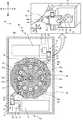
本開示の部品実装機の実施形態について図面を参照しながら以下に説明する。図1は部品実装機10の概略構成を示す斜視図、図2は実装ヘッド40の概略構成を示す説明図、図3はZ軸駆動装置60の配置を示す上面図、図4は圧力供給装置80の概略構成を示す説明図である。また、図5はノズルホルダ42,スプールバルブ46及びバルブ駆動装置70の位置関係を示す説明図、図6は図4のB−B断面図、図7はバルブ駆動装置70がスプールバルブ46を切替える様子を示す説明図、図8は部品実装機10の電気的な接続関係を示す説明図である。図5のうちヘッド本体41の断面図は、図4のA−A断面図である。なお、図1の左右方向がX軸方向であり、前(手前)後(奥)方向がY軸方向であり、上下方向がZ軸方向である。 An embodiment of the component mounting machine of the present disclosure will be described below with reference to the drawings. FIG. 1 is a perspective view showing a schematic configuration of a
部品実装機10は、基材の一例としての基板12に部品を実装する装置である。部品実装機10は、図1に示すように、基台11と、部品供給装置20と、基板搬送装置25と、XYロボット30と、実装ヘッド40と、パーツカメラ28と、制御装置90(図8参照)とを備えている。 The
部品供給装置20は、水平面(XY平面)に平行な配列方向に並ぶように複数設けられている。本実施形態では、部品供給装置20は部品実装機10の前側に配置され、部品供給装置20の配列方向は左右方向(X軸方向)とした。複数の部品供給装置20の各々は、所定間隔毎に形成された収容部に部品Pが収容されたテープを送り出すことにより、部品Pを供給するテープフィーダとして構成されている。 A plurality of
基板搬送装置25は、基板12を水平面(XY平面)に平行な搬送方向に搬送する装置である。本実施形態では、搬送方向は左右方向(X軸方向)とした。基板搬送装置25は、図1に示すように、前後に間隔を開けて設けられ左右方向に架け渡された1対のコンベアベルト26,26(図1では一方のみ図示)を有している。基板12はこのコンベアベルト26,26により搬送方向に搬送されて所定の取込位置に到達すると、裏面側に多数立設された支持ピン27によって支持される。 The
XYロボット30は、実装ヘッド40を水平面(XY平面)に平行に移動させる装置である。XYロボット30は、図1に示すように、前後方向(Y軸方向)に沿って設けられた左右一対のY軸ガイドレール33,33と、左右一対のY軸ガイドレール33,33に架け渡されたY軸スライダ34とを備えている。また、XYロボット30は、Y軸スライダ34の前面に左右方向(X軸方向)に沿って設けられたX軸ガイドレール31,31と、X軸ガイドレール31,31に取り付けられたX軸スライダ32とを備えている。X軸スライダ32は、X軸モータ36(図8参照)の駆動によってX軸方向に移動可能であり、Y軸スライダ34は、Y軸モータ38(図8参照)の駆動によってY軸方向に移動可能である。X軸スライダ32には実装ヘッド40が取り付けられている。実装ヘッド40は、XYロボット30が移動することにより、XY平面上の任意の位置に移動される。 The XY
実装ヘッド40は、部品を採取して基板12に実装する装置である。実装ヘッド40は、図2に示すように、筐体40aと、フレーム40bと、ヘッド本体41と、ノズルホルダ42と、ノズル44と、スプールバルブ46と、を備えている。また、実装ヘッド40は、R軸駆動装置50と、Q軸駆動装置54と、Z軸駆動装置60と、バルブ駆動装置70と、圧力供給装置80とを備えている。筐体40aは、実装ヘッド40の外装であり、略直方体形状をしている。筐体40aは、直方体の3辺がそれぞれXYZ軸方向に沿っている。筐体40aの後側にはX軸スライダ32が取り付けられている(図3参照)。なお、筐体40aは一部(例えば下面)が開口していてもよく、実装ヘッド40の内部の構造体を完全に覆っていなくてもよい。フレーム40bは、筐体40a内に配設されている。 The mounting
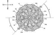
ヘッド本体41は、円柱状の回転体である。ヘッド本体41には、複数のホルダ孔41a及びスプール孔41bが空けられている。ノズルホルダ42は、図3及び図5に示すように、ヘッド本体41の周方向に沿って所定間隔で複数設けられて、円周上に配置されている。これにより実装ヘッド40はロータリーヘッドとして構成されている。複数のノズルホルダ42の各々は、ホルダ孔41aを貫通しており、上下動可能にヘッド本体41に取り付けられている。ノズル44は、各ノズルホルダ42の先端部に交換可能に取り付けられている。ノズル44は、ノズルホルダ42を介してヘッド本体41に取り付けられており、ヘッド本体41の周方向に沿って円周上に配置されている。ノズル44は、圧力供給装置80から供給される負圧の作用によって部品を先端に吸着して保持する。ノズルホルダ42及びノズル44が配置された円周の中心は、ヘッド本体41の中心と一致している。本実施形態では、ヘッド本体41にはノズルホルダ42及びノズル44がそれぞれ12本ずつ取り付けられている。そのため、隣り合うノズルホルダ42同士は、ヘッド本体41の周方向に沿って30°の間隔で配置されている。ノズル44についても同様である。図5及び図6に示す符号A〜Lは、各ノズルホルダ42の識別記号であり、12本のノズルホルダ42を、図の3時の位置にあるノズルホルダ42から左回りにそれぞれA〜Lホルダと称する。同様に、A〜Lホルダの各々に取り付けられたノズル44をそれぞれA〜Lノズルと称する。 The
スプールバルブ46は、ヘッド本体41に複数配設され、複数のスプールバルブ46及びノズル44の各々に対応して設けられている。スプールバルブ46は、対応するノズル44に圧力供給装置80からの負圧が供給されるか否かを切り替える切替弁である。本実施形態では、スプールバルブ46は、ノズル44に圧力供給装置80からの負圧が供給されるか負圧が供給されるかを切り替える。スプールバルブ46は、図5及び図6に示すように、ヘッド本体41の周方向に沿って所定間隔で複数設けられて、円周上に配置されている。複数のスプールバルブ46の各々は、スプール孔41b内に挿入されて上下動可能にヘッド本体41に取り付けられている。複数のスプールバルブ46の各々は、図4,7に示すように、円柱状でありスプール孔41bの内径よりも小径の本体部と、本体部よりも大径でありスプール孔41b内の空間を区画する複数(本実施形態では5個)の大径部47と、を備えている。本実施形態では、ヘッド本体41にはスプールバルブ46が12本(ノズル44と同数)取り付けられている。そのため、隣り合うスプールバルブ46同士は、ヘッド本体41の周方向に沿って30°の間隔で配置されている。図5,6に示す符号a〜lは、各スプールバルブ46の識別記号であり、12本のスプールバルブ46を、図の1時半の位置にあるスプールバルブ46から左回りにそれぞれa〜lバルブと称する。a〜lバルブは、それぞれA〜Lノズルと対応しており、対応するノズルに供給される負圧の有無を切り替える。図5,6からわかるように、複数のスプールバルブ46の各々は、対応するノズル44に対してヘッド本体41の円周の径方向からずれた位置に配置されている。例えばaバルブは、Aノズルに対してヘッド本体41の円周の径方向(図5の左右方向)から角度θだけ周方向で左回りにずれた位置に配置されている。b〜lバルブも、それぞれ対応するB〜Lノズルに対して径方向から角度θだけずれた位置に配置されている。本実施形態では、角度θは45°とした。なお、上述したように隣り合うノズルホルダ42の間隔(ノズルピッチ)は30°であるため、45°は1.5ノズルピッチに相当する。 A plurality of
なお、複数のスプールバルブ46の各々は、下端に操作レバー49を有している(図2,4参照)。操作レバー49は、平板上の部材である。操作レバー49は、先端にバルブ駆動装置70からの駆動力を受けて操作される被操作部49aを有している。図5に示すように、被操作部49aは、操作レバー49のうち上面視でヘッド本体41よりも外側に突出した部分である。この被操作部49aがバルブ駆動装置70からの駆動力を受けることでスプールバルブ46が上下動して、ノズル44への負圧の供給の有無を切り替えるようになっている。複数の被操作部49aは、ヘッド本体41及び複数のノズルホルダ42と同心の円周上に配置されている。複数の被操作部49aの各々は、取り付けられているスプールバルブ46に対してヘッド本体41の径方向外側に位置している。換言すると、被操作部49aはスプールバルブ46に対してヘッド本体41の径方向からずれておらず、径方向に沿って配置されている。そのため、a〜lバルブの被操作部49aの各々は、a〜lバルブと同様に、対応するA〜Lノズルに対して径方向から角度θだけずれた位置に配置されている。 Each of the plurality of
R軸駆動装置50は、複数のノズル44を移動させるノズル移動装置である。このR軸駆動装置50は、R軸51と、R軸モータ52と、R軸位置センサ53(図8参照)とを備えている。R軸51は、上下方向に延び、下端がヘッド本体41の中心軸に取り付けられている。R軸51は、フレーム40bに回転自在に支持されている。R軸モータ52は、R軸51の上方に配設されている。R軸位置センサ53は、R軸モータ52の回転位置を検知する。R軸駆動装置50は、R軸モータ52がR軸51を回転駆動することにより、ヘッド本体41を回転させる。ヘッド本体41が回転することにより、ヘッド本体41と共に複数のノズルホルダ42及び複数のノズル44が円周方向に回転移動(公転)する。すなわち、R軸駆動装置50が駆動することで、複数のノズルホルダ42及び複数のノズル44はヘッド本体41の回転軸を中心とした公転軌跡に沿って公転する。なお、ヘッド本体41には複数のスプールバルブ46も取り付けられているため、R軸駆動装置50が駆動することで複数のスプールバルブ46も複数のノズルホルダ42と一体的に回転移動(公転)する。また、R軸駆動装置50は、所定角度(例えば1ノズルピッチ分である30°)ずつヘッド本体41を間欠回転させることにより、ノズル44を所定角度ずつ間欠的に公転させることができる。 The R-
ここで、ノズル44の公転軌跡上には、ノズル44が部品供給装置20からの部品の採取と基板12への部品の実装との少なくとも一方を行うための第1ノズル位置N1及び第2ノズル位置N2が定められている。本実施形態では、上面視で図5におけるAノズルの位置(3時の方向)が第1ノズル位置N1であり、Gノズルの位置(9時の方向)が第2ノズル位置N2である。第1,第2ノズル位置N1,N2は、互いにノズル44の公転軌跡の中心軸を挟んで左右に対向する位置にある。第1,第2ノズル位置N1,N2はノズル44の公転軌跡上の右端及び左端の位置である。R軸駆動装置50は、ヘッド本体41を回転させることで、A〜Lノズルのうちいずれのノズル44が第1,第2ノズル位置N1,N2の各々に位置するかを変更する。 Here, on the revolution trajectory of the
また、被操作部49aの公転軌跡上には、バルブ駆動装置70から被操作部49aを操作するための位置として、第1,第2操作位置W1,W2が定められている。第1,第2操作位置W1,W2の各々は、第1,第2ノズル位置N1,N2に位置するノズル44に対応する被操作部49aの位置として定められている。例えば、図5で第1ノズル位置N1に位置するのはAノズルであるため、この状態でAノズルに対応するaバルブの被操作部49aの位置が、第1操作位置W1である。そのため、第1ノズル位置N1と第1操作位置W1との位置関係は、上述した上述したA〜Lノズルと対応するa〜lバルブの被操作部49aとの位置関係と同じく、ヘッド本体41の径方向から角度θだけずれている。R軸駆動装置50は、ヘッド本体41を回転させることで、a〜lバルブのうちいずれの被操作部49aが第1,第2操作位置W1,W2の各々に位置するかを変更する。また、R軸駆動装置50はA〜Lノズルとa〜lバルブとを一体的に回転させるため、第1,第2ノズル位置N1,N2の各々にA〜Lのいずれのノズル44が位置しても、そのノズル44に対応するスプールバルブ46の被操作部49aが第1,第2操作位置W1,W2に位置することになる。 Further, on the revolution trajectory of the operated
Q軸駆動装置54は、複数のノズル44を同期して回転(自転)させる機構である。図2に示すように、このQ軸駆動装置54は、上下2段のQ軸ギヤ55,56と、ギヤ57a,57bと、Q軸モータ58と、Q軸位置センサ59(図8参照)とを備えている。上下2段のQ軸ギヤ55,56にはR軸51が同軸に挿通されており、且つ、Q軸ギヤ55,56とR軸51とは相対回転可能に構成されている。ギヤ57aは、各ノズルホルダ42の上部に設けられ、下段のQ軸ギヤ55と上下方向にスライド可能に噛み合っている。Q軸モータ58は、上段のQ軸ギヤ56に噛み合うギヤ57bを回転駆動する。Q軸位置センサ59は、Q軸モータ58の回転位置を検知する。Q軸駆動装置54は、Q軸モータ58によりQ軸ギヤ55,56を回転駆動することにより、Q軸ギヤ55と噛み合うギヤ57aを回転させて、各ノズルホルダ42をその中心軸回りに同一回転方向に同一回転量(回転角度)だけ回転させる。これに伴い複数のノズル44も互いに同期して自転する。 The Q-
Z軸駆動装置60は、ノズルホルダ42及びノズル44をZ軸方向に移動(上下動)させる装置である。Z軸駆動装置60は、ノズルホルダ42の公転軌跡上の第1,第2ノズル位置N1,N2に位置するノズルホルダ42を個別に昇降可能であり、第1ノズル位置N1に位置するノズルホルダ42を昇降させる第1Z軸駆動装置60aと、第2ノズル位置N2に位置するノズルホルダ42を昇降させる第2Z軸駆動装置60bとを備えている。第1,第2Z軸駆動装置60a,60bは、ヘッド本体41の左右方向の中央を挟んで左右に対向するように設けられている。また、第1,第2Z軸駆動装置60a,60bは、互いに左右対称に構成されている。第1Z軸駆動装置60aは、Z軸移動体61と、Z軸モータ64と、Z軸位置センサ65(図8参照)とを備えている。Z軸移動体61は、平板状の部材であり、上下方向に延びるボールネジ63に昇降可能に取り付けられている。Z軸移動体61のうち前側の部分には、ノズルホルダ42の上端付近に配設され水平方向に延び出した係合片42aを上下に挟み込む挟持部62が配設されている。Z軸モータ64は、ボールネジ63を回転させることによりZ軸移動体61を昇降させる。Z軸位置センサ65は、Z軸移動体61の上下方向の位置を検知する。第1Z軸駆動装置60aは、Z軸モータ64を駆動してZ軸移動体61をボールネジ63に沿って昇降させることにより、Z軸移動体61と一体化されたノズルホルダ42及びノズル44を昇降させる。第2Z軸駆動装置60bはZ軸移動体61,ボールネジ63,Z軸モータ64を備えており、これらの構成は第1Z軸駆動装置60aと同様であるため、説明を省略する。なお、ノズルホルダ42が公転して第1,第2ノズル位置N1,N2に停止すると、各々のノズルホルダ42の係合片42aが第1,第2Z軸駆動装置60a,60bの挟持部62に挟み込まれる。そのため、第1,第2Z軸駆動装置60a,60bの各々は、第1,第2ノズル位置N1,N2にあるノズルホルダ42及びノズル44を昇降させる。これにより、第1,第2ノズル位置N1,N2に位置するノズル44は、下降して部品供給装置20の部品を採取したり、下降して基板12に部品を実装したりする。なお、ノズルホルダ42が公転して第1,第2ノズル位置N1,N2から移動すると、そのノズルホルダ42の係合片42aが第1,第2Z軸駆動装置60a,60bの挟持部62から抜け出る。 The Z-
なお、本実施形態では、第1,第2Z軸駆動装置60a,60bのZ軸モータ64,64は、いずれも前後方向でヘッド本体41の中央よりも後方に配置されている(図3参照)。これにより、Z軸モータ64,64は、いずれも実装ヘッド40の中でX軸スライダ32に比較的近い位置に配置されている。こうすることで、例えばZ軸モータ64のうち1以上をヘッド本体41の中央よりも前方に配置する場合と比較して、実装ヘッド40の重心を後方のX軸スライダ32に近づけることができる。これにより、実装ヘッド40がX軸スライダ32によってX軸方向に移動する際のピッチング(X軸周りの回転)を抑制することができる。 In the present embodiment, the Z-
バルブ駆動装置70は、スプールバルブ46の切り替えを行う装置である。バルブ駆動装置70は、第1,第2ノズル位置N1,N2に位置するノズル44に対応するスプールバルブ46を個別に切り替え可能である。バルブ駆動装置70は、図5に示すように、第1ノズル位置N1に位置するノズル44に対応するスプールバルブ46を切り替える第1バルブ駆動装置70aと、第2ノズル位置N2に位置するノズル44に対応するスプールバルブ46を切り替える第2バルブ駆動装置70bと、を備えている。第1,第2バルブ駆動装置70a,70bは、ヘッド本体41を挟んで対向するように設けられている。また、第1,第2バルブ駆動装置70a,70bは、ヘッド本体41の中心軸を中心として2回対称となるように配置されている。 The
第1バルブ駆動装置70aは、駆動源71と、駆動力伝達機構73と、を備えている。駆動源71は、例えばステッピングモーターとして構成され、駆動軸72を有する。駆動源71は、駆動軸72の軸方向(ここでは左右方向)が長手方向である略直方体形状をしている。駆動源71は、ヘッド本体41に対して、上面視で駆動源71の長手方向及び駆動軸72の軸方向に直交する方向(ここでは後方)に配置されている。駆動力伝達機構73は、駆動源71からの駆動力を第1操作位置W1に位置する被操作部49aに伝達する機構である。駆動力伝達機構73は、変換機構74と、直線移動部76と、ガイドレール79と、を備えている。変換機構74は、中央を駆動軸72が貫通するように駆動軸72に取り付けられた板状部材と、その板状部材のうち駆動軸72の回転軸から外れた位置から右方向に突出する円柱状の突起部75とを有している。変換機構74は、駆動軸72に出力された回転駆動力によって回転し、その回転運動を直線移動部76の上下方向の直線運動に変換する。直線移動部76は、駆動源71からの駆動力に基づいて直線移動する部材である。直線移動部76は、複数(ここでは2個)の板状部材を接続した部材であり、突起部75を挟持して係合する突起係合部77を一端側に有し、第1操作位置W1に位置する被操作部49aを挟持して係合するレバー係合部78を他端側に有している。直線移動部76を構成する板状部材のうち、突起係合部77を含む板状部材は前後方向に沿う向きに配置され、レバー係合部78を含む板状部材はヘッド本体41の径方向に沿う向きに配置されている。ガイドレール79は、上下方向に沿って設けられており、駆動源71の右側に設けられた部材に取り付けられている。ガイドレール79の右側には直線移動部76が上下動可能に取り付けられており、ガイドレール79は直線移動部76の上下方向の直線移動を許容しつつ直線移動部76を支持する。 The first
この第1バルブ駆動装置70aでは、駆動源71が駆動力を出力すると、駆動軸72と共に変換機構74が回転し、これによって突起部75に係合する直線移動部76は上下に直線移動する。この直線移動により、直線移動部76の突起係合部77は第1操作位置W1に位置する被操作部49aを上下に移動させる。被操作部49aが上下に移動することで、スプールバルブ46も上下に移動し、スプールバルブ46の状態が切り替えられる。図7Aは第1バルブ駆動装置70aが被操作部49aを上昇させた状態の図であり、図7Bは第1バルブ駆動装置70aが被操作部49aを下降させた状態の図である。第2バルブ駆動装置70bは駆動源71及び駆動力伝達機構73を備えており、これらの構成は第1バルブ駆動装置70aと同様であるため、説明を省略する。なお、スプールバルブ46が公転してその被操作部49aが第1,第2ノズル位置N1,N2に停止すると、各々の被操作部49aが第1,第2バルブ駆動装置70a,70bのレバー係合部78に挟み込まれる。また、スプールバルブ46が公転してその被操作部49aが第1,第2ノズル位置N1,N2から移動すると、被操作部49aは第1,第2バルブ駆動装置70a,70bのレバー係合部78から抜け出る。 In the first
なお、第2バルブ駆動装置70bの駆動源71は、水平面(XY平面)に平行且つ基板12の搬送方向に直交する方向(ここではY軸方向すなわち前後方向)で複数のノズル44から見て第1バルブ駆動装置70aの駆動源71とは反対側に配置されている。換言すると、第1,第2バルブ駆動装置70a,70bの駆動源71,71は、上面視で前後方向に沿って複数のノズル44を挟むように互いに反対側に配置されている。なお、本実施形態では、前後方向は、水平面に平行且つ部品供給装置20の配列方向に直交する方向でもある。 The
圧力供給装置80は、複数のノズル44に少なくとも負圧を供給する装置であり、本実施形態では負圧及び正圧を供給する。また、圧力供給装置80が複数のノズル44の各々に負圧と正圧とのいずれを供給するかは、各々のノズル44に対応するスプールバルブ46によって切り替えられる。図4に示すように、圧力供給装置80は、正圧源81aと、負圧源81bと、フレーム通路82a,82bと、ヘッド通路83a,83bと、正圧導入通路84aと、負圧導入通路84bと、正圧供給通路87aと、負圧供給通路87bと、を備える。 The
正圧源81aは例えばコンプレッサとして構成されている。負圧源81bは例えば真空ポンプとして構成されている。正圧源81a及び負圧源81bの少なくとも一方は、実装ヘッド40の外部又は部品実装機10の外部などに配設されていてもよい。フレーム通路82a,82bは、いずれも実装ヘッド40のフレーム40b内に形成され、正圧源81a及び負圧源81bにそれぞれ接続されている。ヘッド通路83a,83bは、それぞれフレーム通路82a,82bと連通し、R軸51及びヘッド本体41の中心軸方向に沿って延びるように形成されている。なお、図4及び図6に示すように、ヘッド通路83aは、R軸51及びヘッド本体41の中心軸を含む円柱状の通路である。ヘッド通路83bは、ヘッド通路83aから離間しつつその周囲を囲むような円筒状(断面がリング状)の通路として、ヘッド通路83aと同軸に形成されている。 The
正圧導入通路84aは、ヘッド通路83aと連通し、ヘッド本体41の中心軸から径方向外側に向かって放射状に延びるように複数形成されている(図5参照)。複数の正圧導入通路84aの各々は、複数のスプールバルブ46の各々と対応して形成されており、対応するスプールバルブ46が挿入されたスプール孔41bに向かって直線的に延びてそのスプール孔41b内と連通している。複数の正圧導入通路84aの各々は、複数のノズルホルダ42及びホルダ孔41aを避けるように形成されている。例えば、ヘッド通路83aからaバルブまで延びる正圧導入通路84aは、上面視でBホルダとCホルダとの間を通るように配設されている。 A plurality of positive
負圧導入通路84bは、ヘッド通路83bと連通し、ヘッド本体41の中心軸側から外側に向かって放射状に延びるように複数形成されている。複数の負圧導入通路84bの各々は、複数のスプールバルブ46の各々と対応して配置されており、対応するスプールバルブ46が挿入されたスプール孔41bに向かって直線的に延びてそのスプール孔41b内と連通している。複数の負圧導入通路84bの各々は、同じスプールバルブ46に対応する正圧導入通路84aの直上に位置し(図4参照)、正圧導入通路84aと同様に複数のノズルホルダ42及びホルダ孔41aを避けるように形成されている。 A plurality of negative
正圧供給通路87aは、ヘッド本体41の内部に複数形成され、各々が複数のスプールバルブ46の各々に対応して形成されている。複数の正圧供給通路87aの各々は、互いに対応するノズルホルダ42とスプールバルブ46との間(例えばAホルダとaバルブとの間)を結ぶように形成されて(図5参照)、ホルダ孔41aとスプール孔41bとを連通させている。 A plurality of positive
負圧供給通路87bは、ヘッド本体41の内部に複数形成され、各々が複数のスプールバルブ46の各々に対応して形成されている。負圧供給通路87bの各々は、対応するスプールバルブ46からそのスプールバルブ46に対応するノズルホルダ42に向かって水平に延びる通路と(図6参照)、その通路から正圧供給通路87aまで真下に延びる通路と(図7参照)を備えている。負圧供給通路87bのうち真下に延びる通路は、下端が正圧供給通路87aと連通している。すなわち、負圧供給通路87bは、同じスプール孔41bから延びる正圧供給通路87aと合流して、この正圧供給通路87aを介してホルダ孔41aと連通している。 A plurality of negative
このバルブ駆動装置70からノズル44に供給される圧力の切り替えについて説明する。図7Aに示すようにスプールバルブ46が上昇した位置にある状態では、スプールバルブ46は、正圧導入通路84aと正圧供給通路87aとをスプール孔41bを介して連通させる。また、スプールバルブ46は、大径部47がスプール孔41b内を区画することで負圧導入通路84bと負圧供給通路87bとの連通を遮断する。これらにより、正圧源81aからの正圧がフレーム通路82a,ヘッド通路83a,正圧導入通路84a,スプール孔41b,及び正圧供給通路87aを介してホルダ孔41a内に供給される。そして、ホルダ孔41a内の正圧がノズルホルダ42の側面に形成された孔を介してノズルホルダ42内に供給され、ノズル44の先端に正圧が供給される。一方、図7Bに示すようにスプールバルブ46が下降した位置にある状態では、スプールバルブ46は、大径部47がスプール孔41b内を区画することで正圧導入通路84aと正圧供給通路87aとの連通を遮断する。また、スプールバルブ46は、負圧導入通路84bと負圧供給通路87bとをスプール孔41bを介して連通させる。これらにより、負圧源81bからの負圧がフレーム通路82b,ヘッド通路83b,負圧導入通路84b,スプール孔41b,負圧供給通路87b,及び正圧供給通路87aを介してホルダ孔41a内に供給される。そのため、ノズル44の先端には負圧が供給される。このように、スプールバルブ46が上昇位置にあるときにはそのスプールバルブ46に対応するノズル44には正圧が供給され、スプールバルブ46が下降位置にあるときには対応するノズル44には負圧が供給される。 The switching of the pressure supplied from the
パーツカメラ28は、図1に示すように、部品供給装置20と基板搬送装置25との間に設けられている。パーツカメラ28は、ノズル44に吸着された部品の姿勢を下方から撮像する。 As shown in FIG. 1, the
制御装置90は、図8に示すように、CPU91を中心とするマイクロプロセッサとして構成されており、CPU91の他に、ROM92やHDD93、RAM94、入出力インタフェース95などを備える。これらはバス96を介して接続されている。制御装置90には、X軸,Y軸位置センサ37,39、R軸位置センサ53、Q軸位置センサ59、及びZ軸位置センサ65,65からの検知信号、及びパーツカメラ28からの画像信号などが入出力インタフェース95を介して入力される。また、制御装置90からは、部品供給装置20、基板搬送装置25、X軸,Y軸モータ36,38、R軸モータ52、Q軸モータ58、Z軸モータ64,64、駆動源71,71、及びパーツカメラ28への制御信号などが入出力インタフェース95を介して出力される。 As shown in FIG. 8, the
次に、部品実装機10が生産処理を行うときの動作について説明する。制御装置90のCPU91は、図示しない管理装置から受信した生産プログラムに基づいて、部品実装機10の各部を制御して複数の部品が実装された基板12を生産する。なお、生産処理の開始時には、複数のスプールバルブ46はいずれも上昇位置にあるものとする。生産処理では、CPU91は、まず、実装ヘッド40を部品供給装置20の上方に移動させる。続いて、CPU91は、複数のノズル44の各々に部品を順次採取させる採取処理を行う。採取処理では、CPU91は、まず、第1,第2ノズル位置N1,N2に位置するノズル44をそれぞれ下降させる。また、CPU91は、第1,第2操作位置W1,W2に位置する被操作部49aを操作して操作レバー49を下降させる。これにより、第1,第2ノズル位置N1,N2に位置するノズル44には負圧が供給されて、これらのノズル44の各々が部品供給装置20から供給された部品を採取して保持する。そして、CPU91は、第1,第2ノズル位置N1,N2に位置するノズル44を上昇させる。なお、第1,第2ノズル位置N1,N2は部品供給装置20の配列方向と同じ左右方向に配列されているから、第1,第2ノズル位置N1,N2に位置するノズル44に同時に部品を採取させることができる。CPU91は、このように第1,第2ノズル位置N1,N2に位置するノズル44に部品を採取させる処理と、R軸駆動装置50により第1,第2ノズル位置N1,N2に位置するノズル44を変更する処理とを交互に行って、全てのノズル44に部品を採取させる。 Next, the operation when the
採取処理を行うと、CPU91は、実装ヘッド40をパーツカメラ28の上方に移動し、各ノズル44に吸着された部品を順次パーツカメラ28で撮像する。そして、各撮像画像に基づいて部品の姿勢を認識し、その姿勢を加味して部品を基板12上に実装する実装処理を行う。実装処理では、CPU91は、まず、第1ノズル位置N1に位置するノズル44が保持している部品が基板12上の実装位置の上方に位置するよう実装ヘッド40を移動させる。次に、CPU91は、パーツカメラ28の撮像画像に基づく部品の姿勢を加味して第1ノズル位置N1に位置するノズル44を適切な向きに自転させ、ノズル44を下降させる。続いて、CPU91は、第1操作位置W1に位置する被操作部49aを操作して操作レバー49を上昇させる。これにより、第1ノズル位置N1に位置するノズル44には正圧が供給されて、ノズル44は部品を離し、部品が基板12に実装される。そして、CPU91は、第1ノズル位置N1に位置するノズル44を上昇させる。CPU91は、このように第1ノズル位置N1に位置するノズル44が保持している部品を基板12に実装する処理と、R軸駆動装置50により第1ノズル位置N1に位置するノズル44を変更する処理とを交互に行って、全てのノズル44の部品を基板12に実装する。なお、CPU91は、第2ノズル位置N2に位置するノズル44を用いて実装処理を行ってもよい。 When the sampling process is performed, the
ここで、本実施形態の構成要素と本開示の構成要素との対応関係を明らかにする。本実施形態の実装ヘッド40が本開示の実装ヘッドに相当し、XYロボット30がヘッド移動装置に相当し、基板搬送装置25が搬送装置に相当し、ノズル44がノズルに相当し、スプールバルブ46が切替弁に相当し、R軸駆動装置50がノズル移動装置に相当し、第1バルブ駆動装置70aが第1駆動装置に相当し、第1バルブ駆動装置70aの駆動源71が第1駆動源に相当し、第2バルブ駆動装置70bが第2駆動装置に相当し、第2バルブ駆動装置70bの駆動源71が第2駆動源に相当する。また、部品供給装置20が部品供給装置に相当する。第1バルブ駆動装置70aの駆動力伝達機構73,直線移動部76,及びガイドレール79がそれぞれ第1駆動力伝達機構,第1直線移動部,及び第1支持部に相当する。第2バルブ駆動装置70bの駆動力伝達機構73,直線移動部76,及びガイドレール79がそれぞれ第2駆動力伝達機構,第2直線移動部,及び第2支持部に相当する。 Here, the correspondence between the components of the present embodiment and the components of the present disclosure will be clarified. The mounting
以上詳述した部品実装機10による実施例の一態様では、第1,第2バルブ駆動装置70a,70bの駆動源71,71が、水平面に平行且つ基板12の搬送方向に直交する方向(ここでは前後方向)に沿って複数のノズル44を挟むように互いに反対側に配置されている。そのため、この部品実装機10では、例えば駆動源71,71が複数のノズル44から見て同じ側(例えばノズル44の前方)に配置されている場合と比較して、実装ヘッド40の小型化が可能になる。なお、第1,第2バルブ駆動装置70a,70bの駆動源71,71は、水平面に平行且つ複数の部品供給装置の配列方向に直交する方向に沿って複数のノズル44を挟むように互いに反対側に配置されている。 In one aspect of the embodiment by the
さらに、部品実装機10による実施例の一態様では、複数のノズル44は円周上に配置されている。また、複数のスプールバルブ46の各々は、対応するノズル44に対して円周の径方向からずれた位置に配置されている。これにより、スプールバルブ46から対応するノズル44までの負圧の供給経路(ここでは負圧供給通路87b)を確保しつつ、複数のノズル44及び複数のスプールバルブ46をより小さい直径の円形の領域内にコンパクトに配置できる。これにより、ヘッド本体41の直径を小さくすることができる。したがって、実装ヘッド40の小型化が可能になる。なお、本実施形態では、上記のように対応するノズル44に対して円周の径方向からずれた位置にスプールバルブ46を配置することで、スプールバルブ46から対応するノズル44までの正圧の供給経路(ここでは正圧供給通路87a)も確保できている。 Further, in one aspect of the embodiment by the
さらにまた、部品実装機10による実施例の一態様では、複数のノズル44は、円周上に配置されている。また、R軸駆動装置50は、複数のノズル44及び複数のスプールバルブ46を一体的に回転移動させる。第1バルブ駆動装置70aは、第1ノズル位置N1に対してノズル44が配置された円周の径方向からずれた位置である第1操作位置W1に駆動源71からの駆動力を伝達する駆動力伝達機構73を有している。第2バルブ駆動装置70bについても、同様の構成の駆動力伝達機構73を有している。複数の被操作部49aは、複数のノズル44と同心の円周上に配置されており、且つ、各々の被操作部49aは、対応するノズル44が第1ノズル位置N1に位置するときには第1操作位置W1に位置し、対応するノズル44が第2ノズル位置N2に位置するときには第2操作位置W2に位置するように、対応するノズル44に対して円周(複数のノズル44が配置された円周)の径方向からずれた位置に配置されている。これらにより、部品実装機10では、第1ノズル位置N1に対応するスプールバルブ46を操作するための第1操作位置W1を、第1ノズル位置N1に対して径方向に沿った位置とは異なる位置に配置することができる。すなわち、第1操作位置W1の配置の自由度が増す。これにより、第1バルブ駆動装置70aの駆動力伝達機構73が実装ヘッド40の小型化を妨げない位置に配置されるように第1操作位置W1を決定しやすくなり、実装ヘッド40を小型化しやすくなる。同様に、第2バルブ駆動装置70bの駆動力伝達機構73が実装ヘッド40の小型化を妨げない位置に配置されるように第2操作位置W2を決定しやすくなり、実装ヘッド40を小型化しやすくなる。例えば、比較例として、図5の第1ノズル位置N1に位置するノズル44(Aノズル)に対応する第1操作位置を、ノズル位置N1の径方向外側の位置(図5のkバルブの被操作部49aとlバルブの被操作部49aとの中間の位置)に配置する場合を考える。この場合、第1バルブ駆動装置70aの駆動力伝達機構73を図5よりもさらに右下まで延ばして配置する必要があり、図5と比べてヘッド本体41の右側に駆動力伝達機構73を配置するスペースが余分に必要になる。そのため、実装ヘッド40が大型化しやすい。これに対して本実施形態の部品実装機10では、図5のように第1操作位置W1を配置しているため、ヘッド本体41の右後方の領域に第1バルブ駆動装置70aの駆動力伝達機構73を配置するにあたり、ヘッド本体41の右端よりも右側になるべく駆動力伝達機構73がはみ出さないようにすることができる。そのため、ヘッド本体41の右端と筐体40aとの間のスペースを小さくでき、実装ヘッド40を小型化しやすい。第2バルブ駆動装置70bの駆動力伝達機構73の配置についても同様である。 Furthermore, in one aspect of the embodiment by the
さらにまた、部品実装機10による実施例の一態様では、第1バルブ駆動装置70aは、第1ノズル位置N1に位置するノズル44に対応するスプールバルブ46に駆動源71からの駆動力を伝達する駆動力伝達機構73を有している。そして、駆動力伝達機構73は、駆動源71からの駆動力に基づいて直線移動す直線移動部76と、その直線移動を許容しつつ直線移動部76を支持するガイドレール79と、を有している。第2バルブ駆動装置70bについても同様の構成を有している。ここで、実装ヘッド40を小型化することを優先して駆動源71とスプールバルブ46との配置を決定すると、両者の位置が離れてしまい、駆動力伝達機構73のうち駆動源71からの駆動力を受ける位置(ここでは変換機構74の位置)とスプールバルブ46に駆動力を伝達する位置(ここではレバー係合部78の位置)とが離れてしまう場合がある。例えば、比較例として、図5と比べて駆動源71の駆動軸72を被操作部49aにより近づける場合を考える。この比較例で、直線移動部76を図5よりも小さく(短く)して変換機構74の位置とレバー係合部78の位置との距離を短くすることができる。しかし、このように駆動軸72を被操作部49aに近づける場合には、駆動源71とヘッド本体41との干渉を避けるために駆動源71を図5の状態から回転させた向きで配置する必要がある。その結果、この比較例では図5に示した筐体40a内には駆動源71が収まらない状態になりやすく、実装ヘッド40が大型化しやすい。これに対し本実施形態では、なるべく筐体40aを小さくして実装ヘッド40を小型化できるような向き及び位置で駆動源71を配置しており、上記の比較例と比べると変換機構74の位置とレバー係合部78の位置とが離れることになる。そのような場合に、ガイドレール79が直線移動部76を支持することで、駆動力伝達機構73の動作を安定化できる。第2バルブ駆動装置70bのガイドレール79についても同様である。 Furthermore, in one embodiment of the embodiment by the
なお、本発明は上述した実施形態に何ら限定されることはなく、本発明の技術的範囲に属する限り種々の態様で実施し得ることはいうまでもない。 It goes without saying that the present invention is not limited to the above-described embodiment, and can be implemented in various aspects as long as it belongs to the technical scope of the present invention.
例えば、上述した実施形態では、第1,第2バルブ駆動装置70a,70bの駆動源71,71を基板12の搬送方向に直交する方向に沿って複数のノズル44を挟むように互いに反対側に配置したが、これに限られない。例えば、駆動源71,71を左右方向に並べて、基板12の搬送方向に沿って複数のノズル44を挟むように互いに反対側に配置してもよい。こうしても、例えば駆動源71,71を複数のノズル44から見て同じ側(例えばノズル44の右側)に配置されている場合と比較して、実装ヘッドの小型化が可能になる。ただし、駆動源71,71を複数のノズル44から見て同じ側に配置してもよい。例えば、駆動源71,71を複数のノズル44よりも後方(X軸スライダ32に近い側)に配置してもよい。 For example, in the above-described embodiment, the
上述した実施形態では、基板12の搬送方向及び部品供給装置20の配列方向は左右方向としたが、これらの少なくとも一方が左右方向とは異なっていてもよい。 In the above-described embodiment, the transport direction of the
上述した実施形態では、複数のスプールバルブ46の各々は、対応するノズル44に対して円周の径方向からずれた位置に配置されていたが、これに限らず複数のスプールバルブ46のうち1以上が対応するノズル44に対して円周の径方向に沿った位置に配置されていてもよい。なお、スプールバルブ46が対応するノズル44に対して円周の径方向に沿った位置に配置されている場合においても、操作レバー49の形状や配置を調整することで、被操作部49aを対応するノズル44に対して円周の径方向からずれた位置に配置することはできる。こうすれば、上述した実施形態と同様に、第1,第2操作位置W1,W2を、第1,第2ノズル位置N1,N2に対して径方向からずれた位置に配置することができる。 In the above-described embodiment, each of the plurality of
上述した実施形態では、複数のスプールバルブ46はいずれも対応するノズル44よりも外側に配置されていたが、スプールバルブ46のうち1以上が対応するノズル44よりも内側に配置されていてもよい。また、上述した実施形態では、複数のスプールバルブ46は同一の円周上に配置されていたが、これに限られない。例えば隣り合うスプールバルブ46が小径の円周上と大径の円周上とに交互に配置されるようにしてもよい。なお、複数のスプールバルブ46の全てが同一の円周上に配置されていない場合でも、複数の被操作部49aは同一の円周上に配置することが好ましい。 In the above-described embodiment, the plurality of
上述した実施形態では、第1,第2操作位置W1,W2を、第1,第2ノズル位置N1,N2に対して径方向からずれた位置に配置したが、これに限らず第1,第2ノズル位置N1,N2に対して径方向に沿った位置に配置してもよい。 In the above-described embodiment, the first and second operation positions W1 and W2 are arranged at positions deviated from the radial direction with respect to the first and second nozzle positions N1 and N2, but the present invention is not limited to this. 2 The nozzle positions N1 and N2 may be arranged along the radial direction.
上述した実施形態では、第1,第2バルブ駆動装置70a,70bはそれぞれ図5に示した駆動力伝達機構73を有していたが、スプールバルブ46に駆動源71からの駆動力を伝達できれば、どのような構成をしていてもよい。また、第1,第2バルブ駆動装置70a,70bは回転対称(上述した実施形態では2回対称)となるように配置されていたが、例えば左右対称や前後対称となるように配置されていてもよいし、対称的に配置されていなくてもよい。 In the above-described embodiment, the first and second
上述した実施形態では、対応するノズル44に供給される圧力をスプールバルブ46が切り替えたが、スプールバルブ46に限らず他の種類の切替弁が対応するノズル44に供給される圧力を切り替えてもよい。 In the above-described embodiment, the
上述した実施形態において、スプールバルブ46は、図7Aの上昇位置と図7Bの下降位置との間の中間位置に配置したときに、正圧導入通路84aと正圧供給通路87aとの連通を遮断し且つ負圧導入通路84bと負圧供給通路87bとの連通を遮断するよう構成されていてもよい。すなわち、スプールバルブ46は、対応するノズル44に正圧も負圧も供給しない状態に切り替え可能であってもよい。 In the above-described embodiment, when the
上述した実施形態では、スプールバルブ46及び被操作部49aは、対応するノズル44に対して角度θ(=45°)だけヘッド本体41の周方向にずれていたが、これに限られない。角度θは10°以上、20°以上などとしてもよい。また、スプールバルブ46及び被操作部49aは、対応するノズル44に対して1.5ノズルピッチ分ずれていたが、このずれ量は1ノズルピッチ以上としてもよいし、1ノズルピッチ超過としてもよい。また、このずれ量は、2ノズルピッチ以下としてもよいし、2ノズルピッチ未満としてもよい。また、スプールバルブ46と被操作部49aとで、対応するノズル44に対する径方向からのずれ量(角度θ)が異なっていてもよい。 In the above-described embodiment, the
上述した実施形態では、Z軸モータ64,64は、いずれも前後方向でヘッド本体41の中央よりも後方に配置されていたが、これに限らず他の配置であってもよい。 In the above-described embodiment, the Z-
上述した実施形態では、12個のノズル44が等間隔で円周上に配設されていたが、ノズル44の数は12個に限定されるものではなく、複数であればよい。例えば8個,20個,又は24個などとしてもよい。 In the above-described embodiment, 12
上述した実施形態では、部品の採取や実装を行うのは2箇所のノズル位置(第1,第2ノズル位置N1,N2)としたが、これに限らず3箇所や4箇所など2箇所以上であってもよい。 In the above-described embodiment, the parts are collected and mounted at two nozzle positions (first and second nozzle positions N1 and N2), but the present invention is not limited to this and the parts are collected and mounted at two or more locations such as three or four locations. There may be.
本開示の部品実装機は、以下のように構成してもよい。 The component mounting machine of the present disclosure may be configured as follows.
本開示の第2の部品実装機は、
部品を採取して基材に実装する実装ヘッドと、
前記実装ヘッドを水平面に平行に移動させるヘッド移動装置と、
前記水平面に平行な配列方向に並べられ各々が前記部品を供給する複数の部品供給装置と、
を備え、
前記実装ヘッドは、
負圧によって前記部品を吸着して保持する複数のノズルと、
前記複数のノズルの各々に対応して設けられ対応する前記ノズルに負圧が供給されるか否かを切り替える複数の切替弁と、
前記複数のノズルを移動させて前記部品の採取及び実装の少なくとも一方を行うための第1ノズル位置及び第2ノズル位置の各々にいずれの前記ノズルが位置するかを変更するノズル移動装置と、
第1駆動源を有し、該第1駆動源からの駆動力によって前記第1ノズル位置に位置する前記ノズルに対応する前記切替弁を切り替える第1駆動装置と、
前記水平面に平行且つ前記配列方向に直交する方向で前記複数のノズルから見て前記第1駆動源とは反対側に配置された第2駆動源を有し、該第2駆動源からの駆動力によって前記第2ノズル位置に位置する前記ノズルに対応する前記切替弁を切り替える第2駆動装置と、
を有する、
ものである。The second component mounting machine of the present disclosure is
A mounting head that collects parts and mounts them on the base material,
A head moving device that moves the mounting head parallel to the horizontal plane,
A plurality of component supply devices arranged in an arrangement direction parallel to the horizontal plane and each supplying the component,
With
The mounting head is
A plurality of nozzles that attract and hold the parts by negative pressure,
A plurality of switching valves provided corresponding to each of the plurality of nozzles and switching whether or not a negative pressure is supplied to the corresponding nozzles.
A nozzle moving device that moves the plurality of nozzles to change which nozzle is located at each of the first nozzle position and the second nozzle position for collecting and mounting the component.
A first drive device having a first drive source and switching the switching valve corresponding to the nozzle located at the first nozzle position by a driving force from the first drive source.
It has a second drive source arranged on the side opposite to the first drive source when viewed from the plurality of nozzles in a direction parallel to the horizontal plane and orthogonal to the arrangement direction, and a driving force from the second drive source. A second drive device that switches the switching valve corresponding to the nozzle located at the second nozzle position, and
Have,
It is a thing.
この第2の部品実装機では、第1駆動源と第2駆動源とが、水平面に平行且つ複数の部品供給装置の配列方向に直交する方向に沿って複数のノズルを挟むように互いに反対側に配置されている。そのため、この第2の部品実装機では、例えば第1駆動源と第2駆動源とが複数のノズルから見て同じ側に配置されている場合と比較して、実装ヘッドの小型化が可能になる。 In this second component mounting machine, the first drive source and the second drive source are opposite to each other so as to sandwich a plurality of nozzles in a direction parallel to the horizontal plane and orthogonal to the arrangement direction of the plurality of component supply devices. Is located in. Therefore, in this second component mounting machine, the mounting head can be downsized as compared with the case where the first drive source and the second drive source are arranged on the same side when viewed from a plurality of nozzles, for example. Become.
本開示の第3の部品実装機は、
部品を採取して基材に実装する実装ヘッドと、
前記実装ヘッドを水平面に平行に移動させるヘッド移動装置と、
前記基材を前記水平面に平行な搬送方向に搬送する搬送装置と、
を備え、
前記実装ヘッドは、
負圧によって前記部品を吸着して保持する複数のノズルと、
前記複数のノズルの各々に対応して設けられ対応する前記ノズルに負圧が供給されるか否かを切り替える複数の切替弁と、
前記複数のノズルを移動させて前記部品の採取及び実装の少なくとも一方を行うための第1ノズル位置及び第2ノズル位置の各々にいずれの前記ノズルが位置するかを変更するノズル移動装置と、
第1駆動源を有し、該第1駆動源からの駆動力によって前記第1ノズル位置に位置する前記ノズルに対応する前記切替弁を切り替える第1駆動装置と、
前記搬送方向で、又は前記水平面に平行且つ前記搬送方向に直交する方向で前記複数のノズルから見て前記第1駆動源とは反対側に配置された第2駆動源を有し、該第2駆動源からの駆動力によって前記第2ノズル位置に位置する前記ノズルに対応する前記切替弁を切り替える第2駆動装置と、
を有する、
ものである。The third component mounting machine of the present disclosure is
A mounting head that collects parts and mounts them on the base material,
A head moving device that moves the mounting head parallel to the horizontal plane,
A transport device that transports the base material in a transport direction parallel to the horizontal plane, and
With
The mounting head is
A plurality of nozzles that attract and hold the parts by negative pressure,
A plurality of switching valves provided corresponding to each of the plurality of nozzles and switching whether or not a negative pressure is supplied to the corresponding nozzles.
A nozzle moving device that moves the plurality of nozzles to change which nozzle is located at each of the first nozzle position and the second nozzle position for collecting and mounting the component.
A first drive device having a first drive source and switching the switching valve corresponding to the nozzle located at the first nozzle position by a driving force from the first drive source.
The second drive source is arranged on the side opposite to the first drive source when viewed from the plurality of nozzles in the transport direction or in a direction parallel to the horizontal plane and orthogonal to the transport direction. A second drive device that switches the switching valve corresponding to the nozzle located at the second nozzle position by the driving force from the drive source, and
Have,
It is a thing.
この第3の部品実装機では、第1駆動源と第2駆動源とが、搬送方向に沿って複数のノズルを挟むように互いに反対側に配置されているか、又は、水平面に平行且つ基材の搬送方向に直交する方向に沿って複数のノズルを挟むように互いに反対側に配置されている。そのため、この第3の部品実装機では、例えば第1駆動源と第2駆動源とが複数のノズルから見て同じ側に配置されている場合と比較して、実装ヘッドの小型化が可能になる。 In this third component mounting machine, the first drive source and the second drive source are arranged on opposite sides of each other so as to sandwich a plurality of nozzles along the transport direction, or are parallel to the horizontal plane and the base material. The nozzles are arranged on opposite sides of each other so as to sandwich the plurality of nozzles along a direction orthogonal to the transport direction of the nozzle. Therefore, in this third component mounting machine, the mounting head can be downsized as compared with the case where the first drive source and the second drive source are arranged on the same side when viewed from a plurality of nozzles, for example. Become.
本開示の第1〜第3の部品実装機において、前記複数のノズルは、円周上に配置されており、前記複数の切替弁の各々は、対応する前記ノズルに対して前記円周の径方向からずれた位置に配置されていてもよい。こうすれば、切替弁から対応するノズルまでの負圧の供給経路を確保しつつ、複数のノズル及び複数の切替弁をより小さい直径の円形の領域内にコンパクトに配置できる。これにより、実装ヘッドの小型化が可能になる。 In the first to third component mounting machines of the present disclosure, the plurality of nozzles are arranged on the circumference, and each of the plurality of switching valves has a diameter of the circumference with respect to the corresponding nozzle. It may be arranged at a position deviated from the direction. In this way, the plurality of nozzles and the plurality of switching valves can be compactly arranged in a circular region having a smaller diameter while ensuring a negative pressure supply path from the switching valve to the corresponding nozzle. This makes it possible to reduce the size of the mounting head.
本開示の第1〜第3の部品実装機において、前記複数のノズルは、円周上に配置されており、前記ノズル移動装置は、前記複数のノズル及び前記複数の切替弁を一体的に回転移動させ、前記第1駆動装置は、前記第1ノズル位置に対して前記円周の径方向からずれた位置である第1操作位置に前記第1駆動源からの駆動力を伝達する第1駆動力伝達機構を有し、前記第2駆動装置は、前記第2ノズル位置に対して前記円周の径方向からずれた位置である第2操作位置に前記第2駆動源からの駆動力を伝達する第2駆動力伝達機構を有し、前記複数の切替弁の各々は、前記第1駆動力伝達機構及び前記第2駆動力伝達機構からの駆動力を受ける被操作部を有しており、複数の前記被操作部は、前記複数のノズルと同心の円周上に配置されており、且つ、各々の前記被操作部は、対応する前記ノズルが前記第1ノズル位置に位置するときには前記第1操作位置に位置し、対応する前記ノズルが前記第2ノズル位置に位置するときには前記第2操作位置に位置するように、対応する前記ノズルに対して前記円周の径方向からずれた位置に配置されていてもよい。この部品実装機では、複数のノズルが円周上に配置されている。また、切替弁の被操作部が、切替弁に対応するノズルに対して、その円周の径方向からずれた位置に配置されている。そのため、第1ノズル位置に対応する切替弁を操作するための第1操作位置を、第1ノズル位置に対して径方向に沿った位置とは異なる位置に配置することができる。すなわち、第1操作位置の配置の自由度が増す。これにより、第1駆動力伝達機構が実装ヘッドの小型化を妨げない位置に配置されるように第1操作位置を決定しやすくなり、実装ヘッドを小型化しやすくなる。同様に、第2駆動力伝達機構が実装ヘッドの小型化を妨げない位置に配置されるように第2操作位置を決定しやすくなり、実装ヘッドを小型化しやすくなる。 In the first to third component mounting machines of the present disclosure, the plurality of nozzles are arranged on the circumference, and the nozzle moving device integrally rotates the plurality of nozzles and the plurality of switching valves. The first drive device is moved, and the first drive device transmits the driving force from the first drive source to the first operation position, which is a position deviated from the radial direction of the circumference with respect to the first nozzle position. The second driving device has a force transmitting mechanism, and the second driving device transmits the driving force from the second driving source to a second operating position which is a position deviated from the radial direction of the circumference with respect to the second nozzle position. Each of the plurality of switching valves has a first driving force transmission mechanism and an operated portion that receives a driving force from the second driving force transmission mechanism. The plurality of operated portions are arranged on a circumference concentric with the plurality of nozzles, and each of the operated portions is the first when the corresponding nozzle is located at the first nozzle position. Positioned at a position deviated from the radial direction of the circumference with respect to the corresponding nozzle so that it is located at one operating position and is located at the second operating position when the corresponding nozzle is located at the second nozzle position. It may be arranged. In this component mounting machine, a plurality of nozzles are arranged on the circumference. Further, the operated portion of the switching valve is arranged at a position deviated from the radial direction of the circumference of the nozzle corresponding to the switching valve. Therefore, the first operation position for operating the switching valve corresponding to the first nozzle position can be arranged at a position different from the position along the radial direction with respect to the first nozzle position. That is, the degree of freedom in arranging the first operation position is increased. As a result, it becomes easy to determine the first operation position so that the first driving force transmission mechanism is arranged at a position that does not hinder the miniaturization of the mounting head, and it becomes easy to miniaturize the mounting head. Similarly, it becomes easy to determine the second operation position so that the second driving force transmission mechanism is arranged at a position that does not hinder the miniaturization of the mounting head, and it becomes easy to miniaturize the mounting head.
本開示の第1〜第3の部品実装機において、前記第1駆動装置は、前記第1ノズル位置に位置する前記ノズルに対応する前記切替弁に前記第1駆動源からの駆動力を伝達する第1駆動力伝達機構を有し、前記第1駆動力伝達機構は、前記第1駆動源からの駆動力に基づいて直線移動する第1直線移動部と、該直線移動を許容しつつ該第1直線移動部を支持する第1支持部と、を有し、前記第2駆動装置は、前記第2ノズル位置に位置する前記ノズルに対応する前記切替弁に前記第2駆動源からの駆動力を伝達する第2駆動力伝達機構を有し、前記第2駆動力伝達機構は、前記第2駆動源からの駆動力に基づいて直線移動する第2直線移動部と、該直線移動を許容しつつ該第2直線移動部を支持する第2支持部と、を有していてもよい。ここで、実装ヘッドを小型化することを優先して第1駆動源と切替弁との配置を決定すると、両者の位置が離れてしまい、第1駆動力伝達機構のうち第1駆動部からの駆動力を受ける位置と切替弁に駆動力を伝達する位置とが離れてしまう場合がある。そのような場合に、第1支持部が第1直線移動部を支持することで、第1駆動力伝達機構の動作を安定化できる。同様に、第2支持部が第2直線移動部を支持することで、第2駆動力伝達機構の動作を安定化できる。 In the first to third component mounting machines of the present disclosure, the first drive device transmits the driving force from the first drive source to the switching valve corresponding to the nozzle located at the first nozzle position. The first driving force transmission mechanism has a first driving force transmission mechanism, and the first driving force transmission mechanism includes a first linear moving unit that linearly moves based on the driving force from the first driving source, and the first linear moving unit while allowing the linear movement. The second drive device has a first support portion that supports one linear moving portion, and the second drive device has a driving force from the second drive source on the switching valve corresponding to the nozzle located at the second nozzle position. The second driving force transmission mechanism has a second driving force transmission mechanism that transmits the second driving force, and allows the second linear moving portion that linearly moves based on the driving force from the second driving source and the linear movement. However, it may have a second support portion that supports the second linear moving portion. Here, if the arrangement of the first drive source and the switching valve is determined with priority given to miniaturization of the mounting head, the positions of the first drive source and the switching valve are separated from each other, and the first drive unit of the first drive force transmission mechanism is used. The position where the driving force is received and the position where the driving force is transmitted to the switching valve may be separated from each other. In such a case, the operation of the first driving force transmission mechanism can be stabilized by supporting the first linear moving portion by the first supporting portion. Similarly, by supporting the second linear moving portion by the second supporting portion, the operation of the second driving force transmission mechanism can be stabilized.
本開示の第4の部品実装機は、
部品を採取して基材に実装する実装ヘッドと、
前記実装ヘッドを移動させるヘッド移動装置と、
を備え、
前記実装ヘッドは、
円周上に配置され、負圧によって前記部品を吸着して保持する複数のノズルと、
前記複数のノズルの各々に対応して設けられ対応する前記ノズルに負圧が供給されるか否かを切り替える複数の切替弁と、
前記複数のノズル及び前記複数の切替弁を一体的に回転移動させて前記部品の採取及び実装の少なくとも一方を行うためのノズル位置にいずれの前記ノズルが位置するかを変更するノズル移動装置と、
駆動源と、前記ノズル位置に対して前記円周の径方向からずれた位置である操作位置に前記駆動源からの駆動力を伝達する駆動力伝達機構と、
を有し、
前記複数の切替弁の各々は、前記駆動力伝達機構からの駆動力を受ける被操作部を有しており、該被操作部が受けた駆動力によって前記ノズルに負圧が供給されるか否かを切り替えるように構成され、
複数の前記被操作部は、前記複数のノズルと同心の円周上に配置されており、且つ、各々の前記被操作部は、対応する前記ノズルが前記ノズル位置に位置するときには前記操作位置に位置するように、対応する前記ノズルに対して前記円周の径方向からずれた位置に配置されている、
部品実装機。The fourth component mounting machine of the present disclosure is
A mounting head that collects parts and mounts them on the base material,
A head moving device for moving the mounting head and
With
The mounting head is
A plurality of nozzles arranged on the circumference to attract and hold the component by negative pressure,
A plurality of switching valves provided corresponding to each of the plurality of nozzles and switching whether or not a negative pressure is supplied to the corresponding nozzles.
A nozzle moving device that integrally rotates and moves the plurality of nozzles and the plurality of switching valves to change which nozzle is located at a nozzle position for collecting and mounting at least one of the parts.
A drive source, a drive force transmission mechanism that transmits the drive force from the drive source to an operation position that is deviated from the radial direction of the circumference with respect to the nozzle position, and
Have,
Each of the plurality of switching valves has an operated portion that receives a driving force from the driving force transmission mechanism, and whether or not a negative pressure is supplied to the nozzle by the driving force received by the operated portion. It is configured to switch between
The plurality of operated portions are arranged on a circumference concentric with the plurality of nozzles, and each of the operated portions is located at the operating position when the corresponding nozzle is located at the nozzle position. It is arranged so as to be located at a position deviated from the radial direction of the circumference with respect to the corresponding nozzle.
Parts mounting machine.
この第4の部品実装機では、複数のノズルが円周上に配置されている。また、切替弁の被操作部が、切替弁に対応するノズルに対して、その円周の径方向からずれた位置に配置されている。そのため、ノズル位置に対応する切替弁を操作するための操作位置を、ノズル位置に対して径方向に沿った位置とは異なる位置に配置することができる。すなわち、操作位置の配置の自由度が増す。これにより、駆動力伝達機構が実装ヘッドの小型化を妨げない位置に配置されるように操作位置を決定しやすくなり、実装ヘッドを小型化しやすくなる。なお、第4の部品実装機において、上述した第1〜第3の部品実装機の種々の態様を採用してもよいし、第1〜第3の部品実装機が備える構成を追加してもよい。 In this fourth component mounting machine, a plurality of nozzles are arranged on the circumference. Further, the operated portion of the switching valve is arranged at a position deviated from the radial direction of the circumference of the nozzle corresponding to the switching valve. Therefore, the operation position for operating the switching valve corresponding to the nozzle position can be arranged at a position different from the position along the radial direction with respect to the nozzle position. That is, the degree of freedom in arranging the operation position is increased. As a result, it becomes easy to determine the operation position so that the driving force transmission mechanism is arranged at a position that does not hinder the miniaturization of the mounting head, and it becomes easy to miniaturize the mounting head. In the fourth component mounting machine, various aspects of the above-mentioned first to third component mounting machines may be adopted, or the configurations provided by the first to third component mounting machines may be added. Good.
本開示の第5の部品実装機は、
部品を採取して基材に実装する実装ヘッドと、
前記実装ヘッドを移動させるヘッド移動装置と、
を備え、
前記実装ヘッドは、
負圧によって前記部品を吸着して保持する複数のノズルと、
前記複数のノズルの各々に対応して設けられ対応する前記ノズルに負圧が供給されるか否かを切り替える複数の切替弁と、
前記複数のノズルを移動させて前記部品の採取及び実装の少なくとも一方を行うためのノズル位置にいずれの前記ノズルが位置するかを変更するノズル移動装置と、
駆動源と、前記ノズル位置に位置する前記ノズルに対応する前記切替弁に前記駆動源からの駆動力を伝達して該切替弁を切り替える駆動力伝達機構と、を有する駆動装置と、
を有し、
前記駆動力伝達機構は、前記駆動源からの駆動力に基づいて直線移動する直線移動部と、該直線移動を許容しつつ該直線移動部を支持する支持部と、を有する、
部品実装機。The fifth component mounting machine of the present disclosure is
A mounting head that collects parts and mounts them on the base material,
A head moving device for moving the mounting head and
With
The mounting head is
A plurality of nozzles that attract and hold the parts by negative pressure,
A plurality of switching valves provided corresponding to each of the plurality of nozzles and switching whether or not a negative pressure is supplied to the corresponding nozzles.
A nozzle moving device that moves the plurality of nozzles to change which nozzle is located at a nozzle position for collecting and mounting at least one of the parts.
A drive device having a drive source and a drive force transmission mechanism that transmits a drive force from the drive source to the switching valve corresponding to the nozzle located at the nozzle position to switch the switching valve.
Have,
The driving force transmission mechanism has a linear moving portion that linearly moves based on the driving force from the driving source, and a supporting portion that supports the linear moving portion while allowing the linear movement.
Parts mounting machine.
この第5の部品実装機は、実装ヘッドの駆動装置が有する駆動力伝達機構が、直線移動部と直線移動部を支持する支持部とを有している。ここで、実装ヘッドを小型化することを優先して駆動源と切替弁との配置を決定すると、両者の位置が離れてしまい、駆動力伝達機構のうち駆動部からの駆動力を受ける位置と切替弁に駆動力を伝達する位置とが離れてしまう場合がある。そのような場合に、支持部が直線移動部を支持することで、駆動力伝達機構の動作を安定化できる。なお、第5の部品実装機において、上述した第1〜第4の部品実装機の種々の態様を採用してもよいし、第1〜第4の部品実装機が備える構成を追加してもよい。 In this fifth component mounting machine, the driving force transmission mechanism included in the driving device of the mounting head has a linear moving portion and a supporting portion for supporting the linear moving portion. Here, if the arrangement of the drive source and the switching valve is determined with priority given to downsizing the mounting head, the positions of the two will be separated from each other, and the position of the drive force transmission mechanism that receives the drive force from the drive unit will be used. The position where the driving force is transmitted to the switching valve may be separated. In such a case, the support portion supports the linear moving portion, so that the operation of the driving force transmission mechanism can be stabilized. In the fifth component mounting machine, various aspects of the above-mentioned first to fourth component mounting machines may be adopted, or the configurations provided by the first to fourth component mounting machines may be added. Good.
本発明は、部品を基板などの基材に実装する作業を行う各種産業に利用可能である。 The present invention can be used in various industries in which components are mounted on a base material such as a substrate.
10 部品実装機、11 基台、12 基板、20 部品供給装置、25 基板搬送装置、26 コンベアベルト、27 支持ピン、28 パーツカメラ、30 XYロボット、31 X軸ガイドレール、32 X軸スライダ、33 Y軸ガイドレール、34 Y軸スライダ、36 X軸モータ、37 X軸位置センサ、38 Y軸モータ、39 Y軸位置センサ、40 実装ヘッド、40a 筐体、40b フレーム、41 ヘッド本体、41a ホルダ孔、41b スプール孔、42 ノズルホルダ、42a 係合片、44 ノズル、46 スプールバルブ、47 大径部、49 操作レバー、49a 被操作部、50 R軸駆動装置、51 R軸、52 R軸モータ、53 R軸位置センサ、54 Q軸駆動装置、55 Q軸ギヤ、56 Q軸ギヤ、57a,57b ギヤ、58 Q軸モータ、59 Q軸位置センサ、60 Z軸駆動装置、60a,60b 第1,第2Z軸駆動装置、61 Z軸移動体、62 挟持部、63 ボールネジ、64 Z軸モータ、65 Z軸位置センサ、70 バルブ駆動装置、70a,70b 第1,第2バルブ駆動装置、71 駆動源、72 駆動軸、73 駆動力伝達機構、74 変換機構、75 突起部、76 直線移動部、77 突起係合部、78 レバー係合部、79 ガイドレール、80 圧力供給装置、81a 正圧源、81b 負圧源、82a,82b フレーム通路、83a,83b ヘッド通路、84a 正圧導入通路、84b 負圧導入通路、87a 正圧供給通路、87b 負圧供給通路、90 制御装置、91 CPU、92 ROM、93 HDD、94 RAM、95 入出力インタフェース、96 バス、N1,N2 第1,第2ノズル位置、W1,W2 第1,第2操作位置。10 parts mounting machine, 11 bases, 12 boards, 20 parts supply device, 25 board transfer device, 26 conveyor belt, 27 support pins, 28 parts camera, 30 XY robot, 31 X-axis guide rail, 32 X-axis slider, 33 Y-axis guide rail, 34 Y-axis slider, 36 X-axis motor, 37 X-axis position sensor, 38 Y-axis motor, 39 Y-axis position sensor, 40 mounting head, 40a housing, 40b frame, 41 head body, 41a holder hole , 41b spool hole, 42 nozzle holder, 42a engaging piece, 44 nozzle, 46 spool valve, 47 large diameter part, 49 operating lever, 49a operated part, 50 R-axis drive, 51 R-axis, 52 R-axis motor, 53 R-axis position sensor, 54 Q-axis drive device, 55 Q-axis gear, 56 Q-axis gear, 57a, 57b gear, 58 Q-axis motor, 59 Q-axis position sensor, 60 Z-axis drive device, 60a, 60b 1st 2nd Z-axis drive, 61 Z-axis moving body, 62 pinch, 63 ball screw, 64 Z-axis motor, 65 Z-axis position sensor, 70 valve drive, 70a, 70b 1st and 2nd valve drive, 71 drive source , 72 drive shaft, 73 drive force transmission mechanism, 74 conversion mechanism, 75 protrusion, 76 linear movement part, 77 protrusion engagement part, 78 lever engagement part, 79 guide rail, 80 pressure supply device, 81a positive pressure source, 81b negative pressure source, 82a, 82b frame passage, 83a, 83b head passage, 84a positive pressure introduction passage, 84b negative pressure introduction passage, 87a positive pressure supply passage, 87b negative pressure supply passage, 90 controller, 91 CPU, 92 ROM , 93 HDD, 94 RAM, 95 input / output interface, 96 bus, N1, N2 first and second nozzle positions, W1, W2 first and second operation positions.
Claims (5)
Translated fromJapanese前記実装ヘッドを水平面に平行に移動させるヘッド移動装置と、
前記基材を前記水平面に平行な搬送方向に搬送する搬送装置と、
を備え、
前記実装ヘッドは、
負圧によって前記部品を吸着して保持する複数のノズルと、
前記複数のノズルの各々に対応して設けられ対応する前記ノズルに負圧が供給されるか否かを切り替える複数の切替弁と、
前記複数のノズルを移動させて前記部品の採取及び実装の少なくとも一方を行うための第1ノズル位置及び第2ノズル位置の各々にいずれの前記ノズルが位置するかを変更するノズル移動装置と、
第1駆動源を有し、該第1駆動源からの駆動力によって前記第1ノズル位置に位置する前記ノズルに対応する前記切替弁を切り替える第1駆動装置と、
前記水平面に平行且つ前記搬送方向に直交する方向で前記複数のノズルから見て前記第1駆動源とは反対側に配置された第2駆動源を有し、該第2駆動源からの駆動力によって前記第2ノズル位置に位置する前記ノズルに対応する前記切替弁を切り替える第2駆動装置と、
を有する、
部品実装機であって、
前記複数のノズルは、円周上に配置されており、
前記ノズル移動装置は、前記複数のノズル及び前記複数の切替弁を一体的に回転移動させ、
前記第1駆動装置は、前記第1ノズル位置に対して前記円周の径方向からずれた位置である第1操作位置に前記第1駆動源からの駆動力を伝達する第1駆動力伝達機構を有し、
前記第2駆動装置は、前記第2ノズル位置に対して前記円周の径方向からずれた位置である第2操作位置に前記第2駆動源からの駆動力を伝達する第2駆動力伝達機構を有し、
前記複数の切替弁の各々は、前記第1駆動力伝達機構及び前記第2駆動力伝達機構からの駆動力を受ける被操作部を有しており、
複数の前記被操作部は、前記複数のノズルと同心の円周上に配置されており、且つ、各々の前記被操作部は、対応する前記ノズルが前記第1ノズル位置に位置するときには前記第1操作位置に位置し、対応する前記ノズルが前記第2ノズル位置に位置するときには前記第2操作位置に位置するように、対応する前記ノズルに対して前記円周の径方向から1ノズルピッチ以上ずれた位置に配置されている、
部品実装機。A mounting head that collects parts and mounts them on the base material,
A head moving device that moves the mounting head parallel to the horizontal plane,
A transport device that transports the base material in a transport direction parallel to the horizontal plane, and
With
The mounting head is
A plurality of nozzles that attract and hold the parts by negative pressure,
A plurality of switching valves provided corresponding to each of the plurality of nozzles and switching whether or not a negative pressure is supplied to the corresponding nozzles.
A nozzle moving device for moving the plurality of nozzles to change which nozzle is located at each of the first nozzle position and the second nozzle position for collecting and mounting the component.
A first drive device having a first drive source and switching the switching valve corresponding to the nozzle located at the first nozzle position by a driving force from the first drive source.
It has a second drive source arranged on the side opposite to the first drive source when viewed from the plurality of nozzles in a direction parallel to the horizontal plane and orthogonal to the transport direction, and a driving force from the second drive source. A second drive device that switches the switching valve corresponding to the nozzle located at the second nozzle position, and
Have,
A component mountingmachine,
The plurality of nozzles are arranged on the circumference, and the plurality of nozzles are arranged on the circumference.
The nozzle moving device integrally rotates and moves the plurality of nozzles and the plurality of switching valves.
The first driving device is a first driving force transmission mechanism that transmits a driving force from the first driving source to a first operating position which is a position deviated from the radial direction of the circumference with respect to the first nozzle position. Have,
The second driving device is a second driving force transmission mechanism that transmits a driving force from the second driving source to a second operating position which is a position deviated from the radial direction of the circumference with respect to the second nozzle position. Have,
Each of the plurality of switching valves has a controlled portion that receives a driving force from the first driving force transmission mechanism and the second driving force transmission mechanism.
The plurality of operated portions are arranged on a circumference concentric with the plurality of nozzles, and each of the operated portions is the first when the corresponding nozzle is located at the first nozzle position. One nozzle pitch or more from the radial direction of the circumference with respect to the corresponding nozzle so that it is located at one operating position and when the corresponding nozzle is located at the second nozzle position, it is located at the second operating position. It is placed in a misaligned position,
Parts mounting machine .
前記実装ヘッドを水平面に平行に移動させるヘッド移動装置と、
前記水平面に平行な配列方向に並べられ各々が前記部品を供給する複数の部品供給装置と、
を備え、
前記実装ヘッドは、
負圧によって前記部品を吸着して保持する複数のノズルと、
前記複数のノズルの各々に対応して設けられ対応する前記ノズルに負圧が供給されるか否かを切り替える複数の切替弁と、
前記複数のノズルを移動させて前記部品の採取及び実装の少なくとも一方を行うための第1ノズル位置及び第2ノズル位置の各々にいずれの前記ノズルが位置するかを変更するノズル移動装置と、
第1駆動源を有し、該第1駆動源からの駆動力によって前記第1ノズル位置に位置する前記ノズルに対応する前記切替弁を切り替える第1駆動装置と、
前記水平面に平行且つ前記配列方向に直交する方向で前記複数のノズルから見て前記第1駆動源とは反対側に配置された第2駆動源を有し、該第2駆動源からの駆動力によって前記第2ノズル位置に位置する前記ノズルに対応する前記切替弁を切り替える第2駆動装置と、
を有する、
部品実装機であって、
前記複数のノズルは、円周上に配置されており、
前記ノズル移動装置は、前記複数のノズル及び前記複数の切替弁を一体的に回転移動させ、
前記第1駆動装置は、前記第1ノズル位置に対して前記円周の径方向からずれた位置である第1操作位置に前記第1駆動源からの駆動力を伝達する第1駆動力伝達機構を有し、
前記第2駆動装置は、前記第2ノズル位置に対して前記円周の径方向からずれた位置である第2操作位置に前記第2駆動源からの駆動力を伝達する第2駆動力伝達機構を有し、
前記複数の切替弁の各々は、前記第1駆動力伝達機構及び前記第2駆動力伝達機構からの駆動力を受ける被操作部を有しており、
複数の前記被操作部は、前記複数のノズルと同心の円周上に配置されており、且つ、各々の前記被操作部は、対応する前記ノズルが前記第1ノズル位置に位置するときには前記第1操作位置に位置し、対応する前記ノズルが前記第2ノズル位置に位置するときには前記第2操作位置に位置するように、対応する前記ノズルに対して前記円周の径方向から1ノズルピッチ以上ずれた位置に配置されている、
部品実装機。A mounting head that collects parts and mounts them on the base material,
A head moving device that moves the mounting head parallel to the horizontal plane,
A plurality of component supply devices arranged in an arrangement direction parallel to the horizontal plane and each supplying the component,
With
The mounting head is
A plurality of nozzles that attract and hold the parts by negative pressure,
A plurality of switching valves provided corresponding to each of the plurality of nozzles and switching whether or not a negative pressure is supplied to the corresponding nozzles.
A nozzle moving device that moves the plurality of nozzles to change which nozzle is located at each of the first nozzle position and the second nozzle position for collecting and mounting the component.
A first drive device having a first drive source and switching the switching valve corresponding to the nozzle located at the first nozzle position by a driving force from the first drive source.
It has a second drive source arranged on the side opposite to the first drive source when viewed from the plurality of nozzles in a direction parallel to the horizontal plane and orthogonal to the arrangement direction, and a driving force from the second drive source. A second drive device that switches the switching valve corresponding to the nozzle located at the second nozzle position, and
Have,
A component mountingmachine,
The plurality of nozzles are arranged on the circumference, and the plurality of nozzles are arranged on the circumference.
The nozzle moving device integrally rotates and moves the plurality of nozzles and the plurality of switching valves.
The first driving device is a first driving force transmission mechanism that transmits a driving force from the first driving source to a first operating position which is a position deviated from the radial direction of the circumference with respect to the first nozzle position. Have,
The second driving device is a second driving force transmission mechanism that transmits a driving force from the second driving source to a second operating position which is a position deviated from the radial direction of the circumference with respect to the second nozzle position. Have,
Each of the plurality of switching valves has a controlled portion that receives a driving force from the first driving force transmission mechanism and the second driving force transmission mechanism.
The plurality of operated portions are arranged on a circumference concentric with the plurality of nozzles, and each of the operated portions is the first when the corresponding nozzle is located at the first nozzle position. One nozzle pitch or more from the radial direction of the circumference with respect to the corresponding nozzle so that it is located at one operating position and when the corresponding nozzle is located at the second nozzle position, it is located at the second operating position. It is placed in a misaligned position,
Parts mounting machine .
前記実装ヘッドを水平面に平行に移動させるヘッド移動装置と、
前記基材を前記水平面に平行な搬送方向に搬送する搬送装置と、
を備え、
前記実装ヘッドは、
負圧によって前記部品を吸着して保持する複数のノズルと、
前記複数のノズルの各々に対応して設けられ対応する前記ノズルに負圧が供給されるか否かを切り替える複数の切替弁と、
前記複数のノズルを移動させて前記部品の採取及び実装の少なくとも一方を行うための第1ノズル位置及び第2ノズル位置の各々にいずれの前記ノズルが位置するかを変更するノズル移動装置と、
第1駆動源を有し、該第1駆動源からの駆動力によって前記第1ノズル位置に位置する前記ノズルに対応する前記切替弁を切り替える第1駆動装置と、
前記搬送方向で、又は前記水平面に平行且つ前記搬送方向に直交する方向で前記複数のノズルから見て前記第1駆動源とは反対側に配置された第2駆動源を有し、該第2駆動源からの駆動力によって前記第2ノズル位置に位置する前記ノズルに対応する前記切替弁を切り替える第2駆動装置と、
を有する、
部品実装機であって、
前記複数のノズルは、円周上に配置されており、
前記ノズル移動装置は、前記複数のノズル及び前記複数の切替弁を一体的に回転移動させ、
前記第1駆動装置は、前記第1ノズル位置に対して前記円周の径方向からずれた位置である第1操作位置に前記第1駆動源からの駆動力を伝達する第1駆動力伝達機構を有し、
前記第2駆動装置は、前記第2ノズル位置に対して前記円周の径方向からずれた位置である第2操作位置に前記第2駆動源からの駆動力を伝達する第2駆動力伝達機構を有し、
前記複数の切替弁の各々は、前記第1駆動力伝達機構及び前記第2駆動力伝達機構からの駆動力を受ける被操作部を有しており、
複数の前記被操作部は、前記複数のノズルと同心の円周上に配置されており、且つ、各々の前記被操作部は、対応する前記ノズルが前記第1ノズル位置に位置するときには前記第1操作位置に位置し、対応する前記ノズルが前記第2ノズル位置に位置するときには前記第2操作位置に位置するように、対応する前記ノズルに対して前記円周の径方向から1ノズルピッチ以上ずれた位置に配置されている、
部品実装機。A mounting head that collects parts and mounts them on the base material,
A head moving device that moves the mounting head parallel to the horizontal plane,
A transport device that transports the base material in a transport direction parallel to the horizontal plane, and
With
The mounting head is
A plurality of nozzles that attract and hold the parts by negative pressure,
A plurality of switching valves provided corresponding to each of the plurality of nozzles and switching whether or not a negative pressure is supplied to the corresponding nozzles.
A nozzle moving device that moves the plurality of nozzles to change which nozzle is located at each of the first nozzle position and the second nozzle position for collecting and mounting the component.
A first drive device having a first drive source and switching the switching valve corresponding to the nozzle located at the first nozzle position by a driving force from the first drive source.
The second drive source is arranged on the side opposite to the first drive source when viewed from the plurality of nozzles in the transport direction or in a direction parallel to the horizontal plane and orthogonal to the transport direction. A second drive device that switches the switching valve corresponding to the nozzle located at the second nozzle position by the driving force from the drive source, and
Have,
A component mountingmachine,
The plurality of nozzles are arranged on the circumference, and the plurality of nozzles are arranged on the circumference.
The nozzle moving device integrally rotates and moves the plurality of nozzles and the plurality of switching valves.
The first driving device is a first driving force transmission mechanism that transmits a driving force from the first driving source to a first operating position which is a position deviated from the radial direction of the circumference with respect to the first nozzle position. Have,
The second driving device is a second driving force transmission mechanism that transmits a driving force from the second driving source to a second operating position which is a position deviated from the radial direction of the circumference with respect to the second nozzle position. Have,
Each of the plurality of switching valves has a controlled portion that receives a driving force from the first driving force transmission mechanism and the second driving force transmission mechanism.
The plurality of operated portions are arranged on a circumference concentric with the plurality of nozzles, and each of the operated portions is the first when the corresponding nozzle is located at the first nozzle position. One nozzle pitch or more from the radial direction of the circumference with respect to the corresponding nozzle so that it is located at one operating position and when the corresponding nozzle is located at the second nozzle position, it is located at the second operating position. It is placed in a misaligned position,
Parts mounting machine .
前記複数の切替弁の各々は、対応する前記ノズルに対して前記円周の径方向からずれた位置に配置されている、
請求項1〜3のいずれか1項に記載の部品実装機。The plurality of nozzles are arranged on the circumference, and the plurality of nozzles are arranged on the circumference.
Each of the plurality of switching valves is arranged at a position deviated from the radial direction of the circumference with respect to the corresponding nozzle.
The component mounting machine according to any one of claims 1 to 3.
前記第1駆動力伝達機構は、前記第1駆動源からの駆動力に基づいて直線移動する第1直線移動部と、該直線移動を許容しつつ該第1直線移動部を支持する第1支持部と、を有し、
前記第2駆動装置は、前記第2ノズル位置に位置する前記ノズルに対応する前記切替弁に前記第2駆動源からの駆動力を伝達する第2駆動力伝達機構を有し、
前記第2駆動力伝達機構は、前記第2駆動源からの駆動力に基づいて直線移動する第2直線移動部と、該直線移動を許容しつつ該第2直線移動部を支持する第2支持部と、を有する、
請求項1〜4のいずれか1項に記載の部品実装機。The first driving device has a first driving force transmission mechanism for transmitting a driving force from the first driving source to the switching valve corresponding to the nozzle located at the first nozzle position.
The first driving force transmission mechanism includes a first linear moving portion that linearly moves based on the driving force from the first driving source, and a first support that supports the first linear moving portion while allowing the linear movement. With a part,
The second driving device has a second driving force transmission mechanism that transmits a driving force from the second driving source to the switching valve corresponding to the nozzle located at the second nozzle position.
The second driving force transmission mechanism includes a second linear moving portion that linearly moves based on the driving force from the second driving source, and a second support that supports the second linear moving portion while allowing the linear movement. With a part,
The component mounting machine according to any one of claims 1 to4.
Applications Claiming Priority (1)
| Application Number | Priority Date | Filing Date | Title |
|---|---|---|---|
| PCT/JP2017/012559WO2018179076A1 (en) | 2017-03-28 | 2017-03-28 | Component mounter |
Publications (2)
| Publication Number | Publication Date |
|---|---|
| JPWO2018179076A1 JPWO2018179076A1 (en) | 2019-11-21 |
| JP6883645B2true JP6883645B2 (en) | 2021-06-09 |
Family
ID=63674588
Family Applications (1)
| Application Number | Title | Priority Date | Filing Date |
|---|---|---|---|
| JP2019508373AActiveJP6883645B2 (en) | 2017-03-28 | 2017-03-28 | Parts mounting machine |
Country Status (5)
| Country | Link |
|---|---|
| US (1) | US11129315B2 (en) |
| EP (1) | EP3606317B1 (en) |
| JP (1) | JP6883645B2 (en) |
| CN (1) | CN110431933B (en) |
| WO (1) | WO2018179076A1 (en) |
Families Citing this family (2)
| Publication number | Priority date | Publication date | Assignee | Title |
|---|---|---|---|---|
| WO2017126031A1 (en)* | 2016-01-19 | 2017-07-27 | 富士機械製造株式会社 | Component mounting machine |
| CN117580354B (en)* | 2024-01-15 | 2024-03-19 | 深圳联宇华电子有限公司 | Suction nozzle device for SMT chip mounter |
Family Cites Families (11)
| Publication number | Priority date | Publication date | Assignee | Title |
|---|---|---|---|---|
| JP2745569B2 (en)* | 1988-10-05 | 1998-04-28 | 松下電器産業株式会社 | Electronic component mounting equipment |
| JPH07120874B2 (en)* | 1989-01-24 | 1995-12-20 | ティーディーケイ株式会社 | Chip component mounting method and device |
| US5377405A (en)* | 1992-07-01 | 1995-01-03 | Yamaha Hatsudoki Kabushiki Kaisha | Method for mounting components and an apparatus therefor |
| JP3313224B2 (en)* | 1994-01-25 | 2002-08-12 | 松下電器産業株式会社 | Electronic component mounting equipment |
| JP3745849B2 (en) | 1996-11-27 | 2006-02-15 | 富士機械製造株式会社 | Circuit component conveyor |
| JP4255162B2 (en)* | 1999-04-01 | 2009-04-15 | 富士機械製造株式会社 | Electrical component mounting method and electrical component mounting system |
| JP3981834B2 (en)* | 2003-11-19 | 2007-09-26 | ソニー株式会社 | Component mounting equipment |
| JP5875038B2 (en)* | 2011-09-21 | 2016-03-02 | 富士機械製造株式会社 | Electronic circuit component mounting machine |
| CN104137667B (en)* | 2012-02-28 | 2016-12-21 | 富士机械制造株式会社 | Component mounter |
| EP2966951B1 (en) | 2013-03-06 | 2017-11-01 | Fuji Machine Mfg. Co., Ltd. | Electronic circuit component mounting machine |
| CN105706543B (en)* | 2013-10-31 | 2018-09-28 | 富士机械制造株式会社 | Component Mounting Machine |
- 2017
- 2017-03-28JPJP2019508373Apatent/JP6883645B2/enactiveActive
- 2017-03-28WOPCT/JP2017/012559patent/WO2018179076A1/ennot_activeCeased
- 2017-03-28EPEP17903103.4Apatent/EP3606317B1/enactiveActive
- 2017-03-28USUS16/495,518patent/US11129315B2/enactiveActive
- 2017-03-28CNCN201780088591.4Apatent/CN110431933B/enactiveActive
Also Published As
| Publication number | Publication date |
|---|---|
| WO2018179076A1 (en) | 2018-10-04 |
| US20200100406A1 (en) | 2020-03-26 |
| CN110431933A (en) | 2019-11-08 |
| EP3606317B1 (en) | 2022-04-20 |
| EP3606317A4 (en) | 2020-03-25 |
| JPWO2018179076A1 (en) | 2019-11-21 |
| CN110431933B (en) | 2020-12-22 |
| EP3606317A1 (en) | 2020-02-05 |
| US11129315B2 (en) | 2021-09-21 |
Similar Documents
| Publication | Publication Date | Title |
|---|---|---|
| EP2966951B1 (en) | Electronic circuit component mounting machine | |
| JP5690605B2 (en) | Duplicate rotary head and electronic circuit component mounting machine | |
| JP6285439B2 (en) | Component transfer equipment for component mounters | |
| KR101122933B1 (en) | Device for mounting electronic parts | |
| JP6883645B2 (en) | Parts mounting machine | |
| CN103249292B (en) | Electronic component mounting apparatus and electronic component mounting method | |
| JPWO2006059457A1 (en) | Alignment device | |
| CN109514214A (en) | Feeding-distribution device and elastic slice fitting machine | |
| EP1653793B1 (en) | Mounting head of electronic component mounting apparatus | |
| JP6016940B2 (en) | Component mounter | |
| JP5747168B2 (en) | Mounting head and component mounting device | |
| WO2014030243A1 (en) | Component mounting device | |
| JP2005277351A (en) | Electronic component mounting equipment | |
| JP2003046295A (en) | Electric component mounting system and electric circuit manufacturing method | |
| JP5850794B2 (en) | Component conveying device and component mounting machine | |
| JP4408741B2 (en) | Component mounting equipment | |
| JP5005360B2 (en) | Nozzle changer and surface mounter | |
| CN223391591U (en) | A bulk material feeder | |
| JP5142899B2 (en) | Electronic component feeder | |
| JP2000124680A (en) | Chucking nozzle changing device for surface-mounting device | |
| CN120245041A (en) | Clamp | |
| JP4999739B2 (en) | Electronic component mounting device | |
| CN120191739A (en) | Lens tray machine and lens production line | |
| JP2002223097A (en) | Component mounting device and component mounting method | |
| JP2008092355A (en) | Imaging control apparatus and surface mounter |
Legal Events
| Date | Code | Title | Description |
|---|---|---|---|
| A621 | Written request for application examination | Free format text:JAPANESE INTERMEDIATE CODE: A621 Effective date:20190808 | |
| A131 | Notification of reasons for refusal | Free format text:JAPANESE INTERMEDIATE CODE: A131 Effective date:20200908 | |
| A521 | Request for written amendment filed | Free format text:JAPANESE INTERMEDIATE CODE: A523 Effective date:20201104 | |
| TRDD | Decision of grant or rejection written | ||
| A01 | Written decision to grant a patent or to grant a registration (utility model) | Free format text:JAPANESE INTERMEDIATE CODE: A01 Effective date:20210427 | |
| A61 | First payment of annual fees (during grant procedure) | Free format text:JAPANESE INTERMEDIATE CODE: A61 Effective date:20210510 | |
| R150 | Certificate of patent or registration of utility model | Ref document number:6883645 Country of ref document:JP Free format text:JAPANESE INTERMEDIATE CODE: R150 | |
| R250 | Receipt of annual fees | Free format text:JAPANESE INTERMEDIATE CODE: R250 | |
| R250 | Receipt of annual fees | Free format text:JAPANESE INTERMEDIATE CODE: R250 |