JP6883628B2 - Control device, information processing method, and program - Google Patents
Control device, information processing method, and programDownload PDFInfo
- Publication number
- JP6883628B2 JP6883628B2JP2019162846AJP2019162846AJP6883628B2JP 6883628 B2JP6883628 B2JP 6883628B2JP 2019162846 AJP2019162846 AJP 2019162846AJP 2019162846 AJP2019162846 AJP 2019162846AJP 6883628 B2JP6883628 B2JP 6883628B2
- Authority
- JP
- Japan
- Prior art keywords
- flight
- flight device
- unit
- display
- control device
- Prior art date
- Legal status (The legal status is an assumption and is not a legal conclusion. Google has not performed a legal analysis and makes no representation as to the accuracy of the status listed.)
- Active
Links
Images


Landscapes
- Control Of Position, Course, Altitude, Or Attitude Of Moving Bodies (AREA)
- Selective Calling Equipment (AREA)
Description
Translated fromJapanese本発明は、飛行装置を操縦するための操縦装置、操縦装置が実行する情報処理方法、操縦装置で実行されるプログラム、及び飛行装置と操縦装置とを含む飛行システムに関する。 The present invention relates to a control device for maneuvering a flight device, an information processing method executed by the control device, a program executed by the control device, and a flight system including the flight device and the control device.
近年、遠隔から操縦することができる飛行装置であるドローンが普及している。特許文献1には、飛行装置に搭載されたカメラによって周囲を撮影し、撮影した画像のデータを、ユーザが飛行装置の操作に用いる端末に送信する技術が開示されている。 In recent years, drones, which are flight devices that can be operated remotely, have become widespread. Patent Document 1 discloses a technique in which a camera mounted on a flight device captures the surroundings and the captured image data is transmitted to a terminal used by a user to operate the flight device.
飛行装置がユーザの視野から外れた場所を飛行しているときは、ユーザは飛行装置に搭載されたカメラが撮影した画像を頼りに飛行装置を操縦することになる。しかしながら、飛行装置に搭載されたカメラが撮影した画像には、飛行装置自体は被写体に含まれないか、含まれたとしてもその一部のみであることが多い。このため、飛行装置に搭載されたカメラが撮影した画像を見ても、ユーザは飛行装置とそれ以外の物との位置関係や距離感等を把握しにくく、飛行装置の操作がしづらいという問題があった。 When the flight device is flying out of the user's field of view, the user operates the flight device by relying on the image taken by the camera mounted on the flight device. However, in the image taken by the camera mounted on the flight device, the flight device itself is often not included in the subject, or even if it is included, only a part thereof is included. For this reason, even if the image taken by the camera mounted on the flight device is viewed, it is difficult for the user to grasp the positional relationship between the flight device and other objects, the sense of distance, etc., and it is difficult to operate the flight device. was there.
そこで、本発明はこれらの点に鑑みてなされたものであり、ユーザの視野から外れている飛行装置の操作性を向上させる技術を提供することを目的とする。 Therefore, the present invention has been made in view of these points, and an object of the present invention is to provide a technique for improving the operability of a flight device that is out of the user's field of view.
本発明の第1の態様は、無線ネットワークを介して飛行装置を操縦するための操縦装置である。この装置は、前記無線ネットワークを介して、前記飛行装置の飛行方向を示す操作命令を前記飛行装置に送信する送信部と、前記無線ネットワークを介して、前記飛行装置の存在位置を示す位置情報を前記飛行装置から受信する位置情報受信部と、前記飛行装置の存在位置とは異なる位置に、仮想の視点を設定する視点設定部と、前記仮想の視点から前記飛行装置を見た場合における前記飛行装置が飛行中の領域を示す飛行画像を、前記操縦装置の表示部に表示させる表示制御部と、を備える。 The first aspect of the present invention is a control device for maneuvering a flight device via a wireless network. This device transmits an operation command indicating the flight direction of the flight device to the flight device via the wireless network, and position information indicating the existence position of the flight device via the wireless network. A position information receiving unit that receives from the flight device, a viewpoint setting unit that sets a virtual viewpoint at a position different from the existing position of the flight device, and the flight when the flight device is viewed from the virtual viewpoint. The device includes a display control unit that displays a flight image showing a flight area on the display unit of the control device.
前記送信部は、前記仮想の視点を基準として決定された前記飛行装置の飛行方向を示す前記操作命令を送信してもよい。 The transmission unit may transmit the operation command indicating the flight direction of the flight device determined with reference to the virtual viewpoint.
前記操縦装置は、前記無線ネットワークを介して、前記飛行装置が撮像した実画像を前記飛行装置から受信する実映像受信部をさらに備えてもよく、前記表示制御部は、前記飛行装置が撮像した実画像を前記表示部に表示させてもよい。 The control device may further include an actual image receiving unit that receives an actual image captured by the flight device from the flight device via the wireless network, and the display control unit is imaged by the flight device. The actual image may be displayed on the display unit.
前記操縦装置は、前記無線ネットワークを介して、前記飛行装置が存在する場所における前記無線ネットワークの通信品質を示す品質情報を受信する品質情報受信部をさらに備えてもよく、前記表示制御部は、前記品質情報を、前記飛行画像に重畳して前記表示部に表示させてもよい。 The control device may further include a quality information receiving unit that receives quality information indicating the communication quality of the wireless network at the place where the flying device exists via the wireless network, and the display control unit may further include a quality information receiving unit. The quality information may be superimposed on the flight image and displayed on the display unit.
前記表示制御部は、前記飛行装置が存在する場所において前記品質情報に含まれる前記無線ネットワークの通信品質が所定の品質よりも低下した場合、前記通信品質が所定の品質よりも向上する領域が存在する方向を示す情報を前記表示部に表示させてもよい。 The display control unit has a region where the communication quality is improved from the predetermined quality when the communication quality of the wireless network included in the quality information is lower than the predetermined quality at the place where the flight device exists. Information indicating the direction in which the flight is performed may be displayed on the display unit.
前記操縦装置は、前記操縦装置のユーザから、前記飛行装置を飛行させる経路上に存在する1又は複数の地点の入力を受け付ける経路受付部をさらに備えてもよく、前記表示制御部は、前記1又は複数の地点に対応する前記飛行画像の領域を、他の領域とは異なる態様として前記表示部に表示させてもよい。 The control device may further include a route reception unit that receives input from one or a plurality of points existing on the path on which the flight device is to be flown from the user of the control device, and the display control unit may include the display control unit. Alternatively, the area of the flight image corresponding to a plurality of points may be displayed on the display unit as a mode different from other areas.
前記操縦装置は、前記飛行装置が前記飛行装置を飛行させる経路から外れたことを前記操縦装置のユーザに通知する通知部をさらに備えてもよい。 The control device may further include a notification unit that notifies the user of the control device that the flight device has deviated from the path through which the flight device is flown.
前記視点設定部は、前記飛行装置が前記飛行装置を飛行させる経路から外れた場合、前記経路と前記飛行装置とが前記飛行画像に含まれるように、前記仮想の視点を設定してもよい。 When the flight device deviates from the path through which the flight device is flown, the viewpoint setting unit may set the virtual viewpoint so that the path and the flight device are included in the flight image.
前記表示制御部は、前記操縦装置を起点とした場合における前記飛行装置の飛行方向を示す情報を、前記表示部に表示させてもよい。 The display control unit may display information indicating the flight direction of the flight device when the control device is the starting point on the display unit.
前記表示制御部は、前記仮想の視点を起点とした場合における前記操縦装置が存在する方向を、前記表示部に表示させてもよい。 The display control unit may display the direction in which the control device exists when the virtual viewpoint is the starting point on the display unit.
前記視点設定部は、前記飛行装置の飛行方向に対して前記飛行装置の後方に、前記仮想の視点を設定してもよい。 The viewpoint setting unit may set the virtual viewpoint behind the flight device with respect to the flight direction of the flight device.
本発明の第2の態様は、情報処理方法である。この方法は、無線ネットワークを介して飛行装置を操縦するための操縦装置が備えるプロセッサが、前記無線ネットワークを介して、前記飛行装置の飛行方向を示す操作命令を前記飛行装置に送信するステップと、前記無線ネットワークを介して、前記飛行装置の存在位置を示す位置情報を前記飛行装置から受信するステップと、前記飛行装置の存在位置とは異なる位置に、仮想の視点を設定するステップと、前記仮想の視点から前記飛行装置を見た場合における前記飛行装置が飛行中の領域を示す飛行画像を、前記操縦装置の表示部に表示させるステップと、を実行する。 A second aspect of the present invention is an information processing method. In this method, a processor included in the control device for maneuvering the flight device via the wireless network transmits an operation command indicating the flight direction of the flight device to the flight device via the wireless network. A step of receiving position information indicating the existing position of the flying device from the flying device via the wireless network, a step of setting a virtual viewpoint at a position different from the existing position of the flying device, and the virtual A step of displaying a flight image showing a region in which the flight device is in flight on the display unit of the control device when the flight device is viewed from the viewpoint of the above is executed.
本発明の第3の態様は、プログラムである。このプログラムは、無線ネットワークを介して飛行装置を操縦するためのコンピュータに、前記無線ネットワークを介して、前記飛行装置の飛行方向を示す操作命令を前記飛行装置に送信する機能と、前記無線ネットワークを介して、前記飛行装置の存在位置を示す位置情報を前記飛行装置から受信する機能と、前記飛行装置の存在位置とは異なる位置に、仮想の視点を設定する機能と、前記仮想の視点から前記飛行装置を見た場合における前記飛行装置が飛行中の領域を示す飛行画像を表示部に表示させる機能と、を実現させる。 A third aspect of the present invention is a program. This program provides a computer for operating a flight device via a wireless network with a function of transmitting an operation command indicating the flight direction of the flight device to the flight device via the wireless network, and the wireless network. A function of receiving position information indicating the existence position of the flight device from the flight device, a function of setting a virtual viewpoint at a position different from the position of the flight device, and the above from the virtual viewpoint. It realizes a function of displaying a flight image showing a flight area of the flight device on a display unit when the flight device is viewed.
本発明の第4の態様は、飛行装置と、無線ネットワークを介して前記飛行装置を操縦するための操縦装置と、を備える飛行システムである。このシステムにおいて、前記操縦装置は、前記無線ネットワークを介して、前記飛行装置の飛行方向を示す操作命令を前記飛行装置に送信する送信部と、前記無線ネットワークを介して、前記飛行装置の存在位置を示す位置情報を前記飛行装置から受信する位置情報受信部と、前記飛行装置の存在位置とは異なる位置に、仮想の視点を設定する視点設定部と、前記仮想の視点から前記飛行装置を見た場合における前記飛行装置が飛行中の領域を示す飛行画像を、前記操縦装置の表示部に表示させる表示制御部と、を備える。前記飛行装置は、前記操縦装置から前記操作命令を受信する受信部と、前記操作命令に基づいて前記飛行装置の飛行を制御する飛行制御部と、前記飛行装置の存在位置を示す位置情報を取得する位置取得部と、前記無線ネットワークを介して、前記位置情報を前記操縦装置に送信する送信部と、を備える。 A fourth aspect of the present invention is a flight system including a flight device and a control device for maneuvering the flight device via a wireless network. In this system, the control device is a transmission unit that transmits an operation command indicating a flight direction of the flight device to the flight device via the radio network, and an existing position of the flight device via the radio network. The position information receiving unit that receives the position information indicating the above from the flight device, the viewpoint setting unit that sets a virtual viewpoint at a position different from the existing position of the flight device, and the flight device from the virtual viewpoint. In this case, the flight device includes a display control unit that displays a flight image showing a flight area on the display unit of the control device. The flight device acquires a receiving unit that receives the operation command from the control device, a flight control unit that controls the flight of the flight device based on the operation command, and position information indicating the existence position of the flight device. A position acquisition unit is provided, and a transmission unit that transmits the position information to the control device via the wireless network.
本発明によれば、ユーザの視野から外れている飛行装置の操作性を向上させることができる。 According to the present invention, it is possible to improve the operability of a flight device that is out of the user's field of view.
<実施の形態の概要>
図1は、実施の形態に係る通信システムSの全体構成を模式的に示す図である。通信システムSは、操縦装置1と、飛行装置2とを備える。操縦装置1と飛行装置2とは互いにペアリングされており、無線ネットワークNを介して互いに通信することができる。操縦装置1は無線ネットワークNを介して飛行装置2を操縦するための装置であり、ユーザは操縦装置1を用いて飛行装置2を操縦することができる。このため飛行装置2は、操縦装置1から操作命令を受信する受信部と、操作命令に基づいて飛行装置2の飛行を制御する飛行制御部と、を備えている。<Outline of the embodiment>
FIG. 1 is a diagram schematically showing an overall configuration of a communication system S according to an embodiment. The communication system S includes a control device 1 and a
操縦装置1は例えばスマートフォン及びタブレット等の通信端末である。操縦装置1はまた、飛行装置2を操縦するための専用のプロポであってもよい。ユーザが操縦装置1を操作すると、操縦装置1は、操作内容に応じた制御情報を飛行装置2に送信する。飛行装置2は、飛行位置及び飛行速度等のような、操縦に必要な飛行情報を操縦装置1に送信する。また、飛行装置2はカメラを有しており、カメラで撮像して生成した画像データを操縦装置1に送信する。 The control device 1 is a communication terminal such as a smartphone or a tablet. The control device 1 may also be a dedicated radio for maneuvering the
操縦装置1及び飛行装置2は、複数の無線通信回線を用いて、制御情報、飛行情報及び画像データを送受信することができる。操縦装置1及び飛行装置2は、携帯電話網の基地局3を介することなく情報を送受信できる第1無線通信回線W1を用いて通信する。操縦装置1及び飛行装置2はまた、携帯電話網の基地局3を介して情報を送受信できる第2無線通信回線W2を用いて通信することもできる。特に、操縦装置1と飛行装置2とが遠く離れているような場合には、操縦装置1と飛行装置2とは第2無線通信回線W2を用いて通信することになる。第1無線通信回線W1は、例えばWi−Fi(登録商標)回線である。第2無線通信回線W2は、例えばLTE(Long Term Evolution)を含む4G(4th Generation)回線である。 The control device 1 and the
ここで、ユーザと飛行装置2とが遠く離れているような場合には、ユーザは飛行装置2を直接目視しながら操縦することは困難である。ユーザと飛行装置2とが遠く離れていなくても、ユーザと飛行装置2との間に構造物等の遮蔽物が存在すれば、ユーザは飛行装置2を目視しながら操縦することはできない。そのため操縦装置1は飛行装置2から受信した画像データを表示するための表示部を備えている。ユーザは飛行装置2を直接目視できなくても、飛行装置2が撮像した画像データを見ることができれば、飛行装置2を構造物等に衝突させてしまうことを回避できる。 Here, when the user and the
ここで、飛行装置2は自機に備えられているカメラで撮像する。このため、飛行装置2が撮影した画像には飛行装置2自体は被写体に含まれないか、含まれたとしてもその一部のみであることが多い。したがって、飛行装置2が撮影した画像データを見ても、ユーザは飛行装置2とそれ以外の物との位置関係や距離感等を把握しにくく、飛行装置の操作がしづらい場合がある。 Here, the
そこで実施の形態に係る飛行装置2は、飛行装置2の存在位置を示す位置情報を取得する位置取得部と、無線ネットワークNを介して、飛行装置2の位置情報(緯度、経度、高度)、速度、方向、姿勢(傾き)、風速、通信品質、及びバッテリー残量に関する情報等の種々の情報を操縦装置1に送信する送信部とも備えている。操縦装置1は、飛行装置2から位置情報を受信し、飛行装置2の存在位置とは異なる位置から飛行装置2を見た場合における、飛行装置2が飛行中の領域を示す画像データを表示部に表示させる。このため、表示部に表示される画像データには、飛行装置2を後ろや横から見た場合の画像となり、飛行装置2を含む画像となる。これにより、ユーザは飛行装置2とそれ以外の物との位置関係や距離感等を把握することが容易になる。結果として、操縦装置1はユーザの視野から外れている飛行装置2の操作性を向上させることができる。
以下、実施の形態に係る操縦装置1についてより詳細に説明する。Therefore, the
Hereinafter, the control device 1 according to the embodiment will be described in more detail.
<操縦装置1の機能構成>
図2は、実施の形態に係る操縦装置1の機能構成を模式的に示す図である。操縦装置1は、通信部10、記憶部11、表示部12、操作部13、品質情報取得部14、及び制御部15を備える。<Functional configuration of control device 1>
FIG. 2 is a diagram schematically showing a functional configuration of the control device 1 according to the embodiment. The control device 1 includes a communication unit 10, a storage unit 11, a
通信部10は、操縦装置1が飛行装置2との間で情報を送受信するための通信インタフェースである。通信部10は送信部100と受信部101とを備える。また受信部101は、位置情報受信部1010、実映像受信部1011、及び品質情報受信部1012を備える。通信部10は、例えばWi−Fiモジュールや携帯電話通信モジュール等の既知の通信モジュールによって実現される。 The communication unit 10 is a communication interface for the control device 1 to send and receive information to and from the
記憶部11は、OS(Operating System)やアプリケーションプログラム等を格納するROM(Read Only Memory)や操縦装置1の作業領域となるRAM(Random Access Memory)、その他の各種情報を格納するSSD(Solid State Drive)等の大容量記憶装置である。 The storage unit 11 stores a ROM (Read Only Memory) for storing an OS (Operating System), an application program, etc., a RAM (Random Access Memory) for a work area of the control device 1, and an SSD (Solid State) for storing various other information. It is a large-capacity storage device such as Drive).
表示部12は、操縦装置1が生成した情報をユーザに視覚的に通知するためのインタフェースである。表示部12は表示領域とタッチパネルとが一体となったタッチスクリーンであってもよく、この場合表示部12は入力インタフェースとしても機能する。 The
操作部13は、ユーザが飛行装置2を操縦するための操作を行うためのデバイスである。操作部13は、例えば、飛行方向及び飛行速度を制御するための操作スティック又はボリュームを含む。表示部12がタッチスクリーンである場合、操作部13は表示部12に表示されるGUI(Graphical User Interface)を用いて全部又は一部が実装されてもよい。 The operation unit 13 is a device for the user to perform an operation for operating the
品質情報取得部14は、操縦装置1が存在する場所における無線ネットワークNの通信品質を示す品質情報を取得する。ここで「無線ネットワークNの通信品質」とは、無線ネットワークNの電波強度のみならず電波干渉度も含まれる。例えば無線ネットワークNの電波強度が弱くなると通信品質が低下する。また無線ネットワークNの電波干渉度が大きい場合には、無線ネットワークNの電波強度が強い場合であっても、無線ネットワークNの通信品質は低下し得る。 The quality
制御部15は、操縦装置1のCPU(Central Processing Unit)やGPU(Graphics Processing Unit)等のプロセッサであり、記憶部11に記憶されたプログラムを実行することによって、操作受付部151、視点設定部152、表示制御部153、経路受付部154、及び通知部155として機能する。 The
操作受付部151は、操作部13の入力を飛行装置2の操作命令に変換する。送信部100は、無線ネットワークNを介して、飛行装置2の飛行方向を示す操作命令を飛行装置2に送信する。位置情報受信部1010は、無線ネットワークNを介して、飛行装置2の存在位置を示す位置情報を飛行装置2から受信する。 The
視点設定部152は、飛行装置2の存在位置とは異なる位置に、仮想の視点を設定する。表示制御部153は、視点設定部152が設定した仮想の視点から飛行装置2を見た場合における飛行装置2が飛行中の領域を示す飛行画像を、操縦装置1の表示部12に表示させる。 The
ここで「仮想の視点」とは、飛行装置2が有するカメラ等の撮像部とは異なり、必ずしも実在しない視点である。視点設定部152は、例えば飛行装置2の進行方向に対して後方10メートル、相対高度で2m上空に設定する。ユーザは操縦装置1の操作スティックを操作することにより、視点設定部152が仮想の視点の設定する場所を変更することができる。また、視点設定部152は、飛行装置2の飛行速度に応じて仮想の視点を設定する位置を変更してもよい。具体的には、視点設定部152は、飛行装置2の飛行速度が速い場合には、遅い場合よりも、飛行装置2から離れた位置に仮想の視点を設定するようにしてもよい。 Here, the "virtual viewpoint" is a viewpoint that does not necessarily exist, unlike the image pickup unit of the
表示制御部153は、例えば既知の地形情報に基づいてCG(Computer Graphics)等の技術によってあらかじめ作成された画像データに基づいて、設定された仮想の視点から飛行装置2を見た場合におけるいわば鳥瞰画像を生成し、表示部12に表示させる。なお、操縦装置1があらかじめ飛行装置2が飛行する空域の映像を撮影して保持している場合には、表示制御部153はその映像を読み出して表示部12に表示させてもよい。また、操縦装置1と飛行装置2とが同一の3次元的な地形情報を記憶している場合には、表示制御部153は、飛行装置2から受信した位置情報と地形情報とに基づいて鳥瞰画像を生成し、表示部12表示してもよい。 The
実映像受信部1011は、無線ネットワークNを介して、飛行装置2が撮像した実画像を飛行装置2から受信する。表示制御部153は、飛行装置2が撮像した実画像を表示部12に表示させる。これにより、ユーザは飛行装置2が撮像した実画像のみならず、飛行装置2を離れた位置から見た場合における鳥瞰画像も表示部12で確認することができる。飛行装置2が他の物体と接近した場合には、ユーザは飛行装置2と他の物体とが両方とも映っている映像を観察することができるようになる。このため、ユーザは飛行装置2と他の物体との位置関係や距離感を直感的に把握することができる。結果として飛行装置2がユーザの視野から外れていても、飛行装置2の操作性が向上する。 The actual image receiving unit 1011 receives the actual image captured by the
なお、飛行装置2が図示しない赤外センサ等の測距センサを備える場合には、飛行装置2は自機の周囲の物体との距離を計測することができる。飛行装置2は、自機と周囲の物体との距離が所定の距離以内となった場合、その旨を操縦装置1に通知する。操縦装置1は、飛行装置2が周囲の物体に所定の距離以内に近づいた場合、操縦装置1の通知部155は、操縦装置1が備える図示しないスピーカに警告音を再生させたり、バイブレータを振動させたりすることにより、飛行装置2が他の物体に接近したことをユーザに通知してもよい。 When the
また、操縦装置1と飛行装置2との少なくともいずれか一方は、記憶している3次元的な地形情報と飛行装置2の位置情報とに基づいて、飛行装置2が他の物体と接近しているか否かを判定してもよい。飛行装置2と他の物体との距離が所定の距離以内となったとき、操縦装置1の通知部155は、操縦装置1が備える図示しないスピーカに警告音を再生させたり、バイブレータを振動させたりすることにより、飛行装置2が他の物体に接近したことをユーザに通知してもよい。 Further, at least one of the control device 1 and the
したがって、「所定の距離」とは、飛行装置2が他の物体と接近したことをユーザに通知するか否かを決定するために通知部155が参照する「接近通知判定用閾距離」である。接近通知判定用閾距離は記憶部11に格納されている。接近通知判定用閾距離の具体的な値は、飛行装置2が回避行動を起こすことによって他の物体を回避可能な距離であり、飛行装置2の飛行性能を考慮して実験により定めればよいが、例えば20メートルである。なお、飛行装置2が他の物体との接近を判定する場合には、飛行装置2は、その時点での風速を考慮して接近通知判定用閾距離を変更してもよい。 Therefore, the "predetermined distance" is the "approach notification determination threshold distance" referred to by the
上述したように、表示制御部153が表示部12に表示させる鳥瞰画像は、CGである。このため、鳥瞰画像は現実の状況を忠実に再現できている保証は必ずしも得られない。そこで、表示制御部153は、鳥瞰画像を表示部12に表示させるときは、実映像も必ず表示部12に表示させるようにしてもよい。これにより、ユーザは飛行装置2の周辺の現実の状況を常に確認することができる。 As described above, the bird's-eye view image displayed on the
図3は、実施の形態に係る操縦装置1の表示部12に表示される操作画面の一例を模式的に示す図である。図3に示す例では、操作画面は品質情報インジケータ301、電池残量インジケータ302、情報パネル303、鳥瞰図表示領域304、飛行装置アイコン305、及びライブ画像表示領域306を含む。 FIG. 3 is a diagram schematically showing an example of an operation screen displayed on the
品質情報インジケータ301は、品質情報取得部14が取得した品質情報、すなわち操縦装置1が存在する場所における無線ネットワークNの通信品質を示すアイコンである。電池残量インジケータ302は、操縦装置1の電池の残量を示すアイコンである。 The
情報パネル303は、飛行装置2の飛行に関する情報を示す。情報パネル303には、操縦装置1と飛行装置2との間の距離、飛行装置2の進行方向、飛行装置2の飛行速度、及び飛行装置2の高度が表示される。 The
鳥瞰図表示領域304は、表示制御部153が表示部12に表示させる鳥瞰画像の表示領域である。図3における鳥瞰図表示領域304は、視点設定部152が飛行装置2の後方に仮想の視点を設定した場合に、表示制御部153が表示部12に表示させる鳥瞰画像の例を示している。このため鳥瞰図表示領域304には、飛行装置2を示す飛行装置アイコン305が含まれる。またライブ画像表示領域306は、飛行装置2が撮像した実画像の表示領域である。 The bird's-eye
図3に示すように、飛行装置アイコン305は鳥瞰図表示領域304の中心に示されている。表示制御部153は、飛行装置2の移動に追従して、飛行装置アイコン305が鳥瞰図表示領域304の中心になるように鳥瞰図表示領域304の表示領域を変更する。また、表示制御部153は、飛行装置2の飛行速度に応じて、鳥瞰図表示領域304の縮尺を変更してもよい。具体的には、表示制御部153は、飛行装置2の飛行速度が速い場合は、遅い場合よりも、広範囲の映像を示す鳥瞰図表示領域304を表示部12に表示させてもよい。 As shown in FIG. 3, the
実施の形態に係る飛行装置2が備えるカメラは、飛行装置2の進行方向前方の風景を撮像する。図3における鳥瞰図表示領域304は、視点設定部152が飛行装置2の後方に仮想の視点を設定した場合における鳥瞰画像であるため、仮想の視点から飛行装置アイコン305に向かう向きが、飛行装置2の進行方向となる。したがって、図3に示すように、視点設定部152が飛行装置2の後方に仮想の視点を設定した場合、鳥瞰図表示領域304に表示される画像とライブ画像表示領域306に表示される画像とは類似したものとなる。 The camera included in the
ところで、ユーザは操縦装置1が備える操作スティック(不図示)を傾倒したり、表示部12に表示された操作用GUI(不図示)を操作したりすることにより、飛行装置2の操作を実行する。例えば、ユーザが操作スティックを「右」に傾倒すると、飛行装置2は「右」に旋回する。 By the way, the user executes the operation of the
ここで「右」や「左」は相対的な方向の概念であり、絶対的な方向を確定するためには何らかの基準が必要となる。そこで実施の形態に係る操縦装置1においては、操作受付部151は視点設定部152が設定した仮想の視点を基準として、飛行装置2の飛行方向を示す操作命令を決定する。送信部100は、操作受付部151が決定した操作命令を飛行装置2に送信する。例えば、飛行装置2の後方に仮想の視点を設定されている場合、ユーザがスティックを「右」に傾倒すると、飛行装置2は進行方向に対して右方向に曲がる。この場合、例えば飛行装置2がユーザに向かって進行しているとすると、ユーザがスティックを「右」に傾倒すると、飛行装置2はユーザから見て左方向に曲がるように見える。 Here, "right" and "left" are concepts of relative direction, and some standard is required to determine the absolute direction. Therefore, in the control device 1 according to the embodiment, the
したがって、仮想の視点が飛行装置2の飛行方向に対して飛行装置2の後方に設定されている場合、ユーザによるスティックの系統方向と、鳥瞰図表示領域304における飛行装置アイコン305の移動方向とが一致することになる。そこで視点設定部152は、飛行装置2の飛行方向に対して飛行装置2の後方に、仮想の視点を設定してもよい。これによりユーザによる操作と飛行装置2の移動方向が一致するため、ユーザは直感的に飛行装置2を操作できるようになる。 Therefore, when the virtual viewpoint is set behind the
なお、飛行装置2が操縦装置1から遠ざかっている場合には、視点設定部152は、操縦装置1と飛行装置2との間に仮想の視点を設定することになる。より具体的には、視点設定部152は、操縦装置1の存在位置と飛行装置2の存在位置とを通る直線における仮想の視点の垂線の足が、操縦装置1の存在位置と飛行装置2の存在位置との間に存在するように、仮想の視点を設定する。 When the
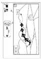
図4は、実施の形態に係る操縦装置1の表示部12に表示される操作画面の別の例を模式的に示す図であり、仮想の視点と飛行装置2との位置関係を示す図である。図4に示す例では、操作画面は品質情報インジケータ301、電池残量インジケータ302、情報パネル303、飛行装置アイコン305、位置関係表示領域307、仮想視点アイコン308、ユーザアイコン309、及び経路マップ310を含む。 FIG. 4 is a diagram schematically showing another example of the operation screen displayed on the
位置関係表示領域307は、操縦装置1、飛行装置2、及び仮想の視点の位置関係を示す領域である。位置関係表示領域307には、飛行装置2の位置を示す飛行装置アイコン305、仮想の視点を示す仮想視点アイコン308、及びユーザ(すなわち操縦装置1)の位置を示すユーザアイコン309が配置されている。位置関係表示領域307にはさらに、飛行装置アイコン305を原点として東西方向を示す軸、南北方向を示す軸、及び高低方向を示す軸による3次元座標系が設定されている。 The positional
図4に示す例では、ユーザは飛行装置2の南西において飛行装置2よりも低い位置に存在しており、仮想の視点は飛行装置2の南において飛行装置2と同じ高さに設定されていることが示されている。この場合、ユーザがスティックを「右」に傾倒すると、飛行装置2は仮想視点アイコン308から見て右側、すなわち東の方向に旋回する。位置関係表示領域307を確認することにより、ユーザは飛行装置2と仮想の視点との位置関係を把握することができる。 In the example shown in FIG. 4, the user exists at a position lower than the
飛行装置2は一般にユーザから離れた上空を飛行するため、操縦装置1と飛行装置2との距離は、視点設定部152が設定した仮想の視点と飛行装置2との距離よりも十分に長いといえる。したがって、位置関係表示領域307は飛行装置2を起点とした場合におけるユーザ(すなわち操縦装置1)が存在する方向を示す情報であるが、これはすなわち仮想の視点を起点とした場合におけるユーザが存在する方向を示す情報ともいえる。表示制御部153が位置関係表示領域307を表示部12に表示させることにより、ユーザは自分自身と仮想の視点との位置関係も容易に把握することができる。 Since the
表示制御部153はまた、飛行装置2のスタート地点と、飛行装置2の到達目標地点とを含む2次元の地図である経路マップ310も表示部12に表示させる。図4に示す経路マップ310の例では、飛行装置2のスタート地点は黒丸で示され、飛行装置2の到達目標地点は白抜きの星形で示されている。また、経路マップ310における飛行装置2の現在位置は黒の三角形で示されており、飛行装置2のスタート地点から飛行装置2の現在位置に至るまでにたどった経路も示されている。 The
経路マップ310は操縦装置1を起点とした場合における飛行装置2の飛行方向を示す情報ともいえる。表示制御部153は経路マップ310を表示部12に表示させることにより、ユーザは、飛行装置2のスタート地点(すなわち、ユーザが存在する地点)、飛行装置2の現在位置、及び飛行装置2の到達目標地点との関係を把握することができる。 The
図2の説明に戻る。経路受付部154は、操縦装置1のユーザから、飛行装置2を飛行させる経路上に存在する1又は複数の地点の入力を受け付ける。具体的には、ユーザは表示部12に表示された地図(不図示)を見ながら、操作部13を操作して飛行装置2の経路を入力する。経路受付部154はユーザによる操作部13の操作を経路情報に変換し、表示制御部153に出力する。表示制御部153は、1又は複数の地点に対応する飛行画像の領域を、他の領域とは異なる態様として表示部12に表示させる。 Returning to the description of FIG. The
なお、実施の形態に係る通信システムSが、第2無線通信回線W2により操縦装置1と接続されたサーバ(不図示)を更に備えており、そのサーバが1又は複数の経路情報を格納している場合には、操縦装置1はサーバから経路情報を受信してもよい。このようにすることで、操縦装置1は、多数の経路情報を記憶させるための記憶部11の記憶容量を増大させる必要がない。 The communication system S according to the embodiment further includes a server (not shown) connected to the control device 1 by the second wireless communication line W2, and the server stores one or a plurality of route information. If so, the control device 1 may receive route information from the server. By doing so, the control device 1 does not need to increase the storage capacity of the storage unit 11 for storing a large amount of route information.
図5は、実施の形態に係る操縦装置1の表示部12に表示される飛行経路が表示された表示画面の一例を模式的に示す図である。図5に示す飛行経路が表示された表示画面の例は、品質情報インジケータ301、電池残量インジケータ302、情報パネル303、鳥瞰図表示領域304、飛行装置アイコン305、及び経路インジケータ311を含む。 FIG. 5 is a diagram schematically showing an example of a display screen on which a flight path displayed on the
図5において、鳥瞰図表示領域304内の符号311で示す矢印は、ユーザによって入力された飛行経路を示す経路インジケータ311である。煩雑となることを防ぐためにすべての矢印に符号を付していないが、図5において符号311が付された矢印と同様の形状の矢印は経路インジケータ311である。図5に示すように、表示制御部153は、ユーザによって入力された飛行経路に対応する箇所を立体的な矢印である経路インジケータ311を表示することにより、他の飛行画像と区別して表示部12に表示させている。ユーザは飛行装置アイコン305と経路インジケータ311とを見ることにより、飛行装置2が設定した飛行経路に沿って飛行しているか否かを一見して把握することができる。 In FIG. 5, the arrow indicated by
ここで通知部155は、飛行装置2が飛行装置2を飛行させる経路から外れたことを操縦装置1のユーザに通知する。通知部155は、飛行装置2が飛行経路から外れた場合、そのことを示すメッセージを表示制御部153を介して表示部12に表示させることによりユーザに通知する。これに替えて、あるいはこれに加えて、通知部155は操縦装置1が備える図示しないスピーカに警告音を再生させたり、バイブレータを振動させたりすることにより、飛行装置2が飛行経路から外れたことをユーザに通知してもよい。これにより、ユーザは飛行装置2が設定した飛行経路から外れたことを迅速に認識することができる。 Here, the
また視点設定部152は、飛行装置2が飛行装置2を飛行させる経路から外れた場合、飛行経路を示す経路インジケータ311と飛行装置2を示す飛行装置アイコン305とが飛行画像に含まれるように、仮想の視点を設定する。これにより、表示制御部153が表示部12に表示させる鳥瞰図表示領域304に飛行経路を示す経路インジケータ311と飛行装置2を示す飛行装置アイコン305とが含まれることになる。鳥瞰図表示領域304を見ることにより、ユーザは飛行装置2を飛行経路に戻すために飛行装置2を移動させるべき方向を把握することができる。 Further, when the
以上は、操縦装置1が飛行装置2から無線ネットワークNを介して飛行装置2の位置情報や飛行装置2が撮像した画像等の情報を受信できることを前提とした。ここで操縦装置1が飛行装置2から遠く離れた場合にはWi−Fiを用いた通信が困難となるため、操縦装置1は、第2無線通信回線W2を介して飛行装置2の位置情報や飛行装置2が撮像した画像等の情報を飛行装置2から受信する。このため、飛行装置2が飛行している領域における第2無線通信回線W2の通信品質は、操縦装置1と飛行装置2との間で情報をやり取りする際に重要となる。 The above is based on the premise that the control device 1 can receive information such as the position information of the
そこで品質情報受信部1012は、第2無線通信回線W2を介して、飛行装置2が存在する場所における第2無線通信回線W2の通信品質を示す品質情報を、飛行装置2から受信する。表示制御部153は、飛行装置2から取得した第2無線通信回線W2の品質情報を、飛行画像に重畳して表示部12に表示させる。 Therefore, the quality
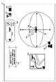
図6は、表示部12に表示される電波強度マップ312の一例を示す図である。図6においては、第2無線通信回線W2の通信品質のエリア毎の分布を示す分布情報を電波強度マップ312として表示している。この電波強度マップ312は、ハッチングラベル313に示すように、第2無線通信回線の電波強度の異なる領域に対し、異なるハッチングを付して区分している。 FIG. 6 is a diagram showing an example of the radio
なお、電波強度マップ312は通信品質の3次元的な分布情報を含むものである。このため、表示制御部153は、地上からの飛行装置2の高度に対応付けて電波強度マップ312を表示させる。この表示画面では、高度35m付近における電波強度マップ312が示されている。ユーザがアップアイコン314を選択する毎に、表示制御部153は高度を5m増加させた電波強度マップを表示させる。また、ユーザがダウンアイコン315を選択する毎に、表示制御部153は高度を5m減少させた電波強度マップを表示させる。 The radio
表示制御部153は、電波強度マップ312の中央に、飛行装置アイコン305を表示させる。この表示画面では、飛行装置2が地上から高度34.2mに位置している場合の例を示している。このように、表示制御部153は、飛行装置2が存在する場所を含む電波強度マップ312に飛行装置2が存在する場所を重畳して表示部12に表示させる。これにより、ユーザは通信品質の良い領域を選んで飛行装置2を飛行させることができる。なお、表示制御部153は、飛行装置2から受信した品質情報を表示部12に表示させることに替えて、記憶部11にあらかじめ格納してある電波強度マップ312を読み出して表示部12に表示させてもよい。 The
飛行装置2が存在する場所の電波強度マップ312が取得できない場合には、表示制御部153は電波強度マップ312に替えて、エリアマップを表示部12に表示させてもよい。ここで「エリアマップ」とは、第2無線通信回線W2の通信が可能か否かを示す通信可能エリアマップであり、既存のスマートフォンの通信状況から作成される既知のマップである。 When the radio
ここで表示制御部153は、飛行装置2が存在する場所において品質情報に含まれる第2無線通信回線W2の通信品質が所定の品質よりも低くなった場合、例えば第2無線通信回線W2の電波強度が所定の閾値以下となった場合には、電波強度が所定の閾値よりも大きくなる領域(すなわち、通信品質が所定の品質よりも向上する領域)が存在する方向を示す情報を表示部12に表示させる。なお、「所定の閾値」とは、操縦装置1から飛行装置2への操作情報の送信に耐えうる通信品質を維持できているか否かを決定するために、表示制御部153が参照する電波強度の判別基準閾値である。判別基準閾値の具体的な値は、操縦装置1及び飛行装置2が備えるアンテナの性能等を考慮して実験により定めればよい。 Here, when the communication quality of the second wireless communication line W2 included in the quality information becomes lower than the predetermined quality in the place where the
図7は、飛行装置2の周辺の電波強度が所定の閾値以下となった場合に表示部12に表示される表示画面を模式的に示す図である。図7に示すように、飛行装置2の周辺の電波強度が所定の閾値以下となった場合、表示部12は電波強度低下メッセージ316を表示する。これにより、ユーザは飛行装置2との通信が途絶える前に、飛行装置2を通信品質の良い環境下に移動させることができる。 FIG. 7 is a diagram schematically showing a display screen displayed on the
ここで、飛行装置2をどの方向に移動させれば通信環境が改善するかを知ることができれば、ユーザにとって有用である。そこで表示制御部153は、飛行装置2が移動した場合に第2無線通信回線W2の通信品質がよくなる方向を、表示部12に表示させる。 Here, it is useful for the user if it is possible to know in which direction the
図7において、方向インジケータ317は飛行装置2が移動した場合に無線ネットワークNの通信品質がよくなる方向を示しており、ユーザアイコン309は飛行装置2の位置を基準とした場合におけるユーザの存在方向を示している。図7に示す例では、ユーザは飛行装置2を北西の方向に上昇させるように操作すれば、無線ネットワークNの通信品質がよくなることを示している。 In FIG. 7, the
なお、図7に示す方向インジケータ317は、飛行装置2が実際に移動することができる方向を示している。表示制御部153は、第2無線通信回線W2の通信品質がよくなる方向であっても、障害物がある等の理由によって飛行装置2が移動できない方向には方向インジケータ317を表示部12に表示させないか、移動できないことを示すアイコン(不図示)を表示させる。 The
ここで飛行装置2は、飛行装置2の周辺の電波強度が所定の閾値以下となった場合、操縦装置1から新たな操作情報が送信されるまでの間その場で空中停止(ホバリング)するようにしてもよい。これにより、飛行装置2がさらに電波強度の低い領域に移動することを防ぐことができる。 Here, when the radio wave intensity around the
<実施の形態に係る操縦装置1が実行する情報処理の処理フロー>
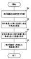
図8は、実施の形態に係る操縦装置1が実行する情報処理の流れを説明するためのフローチャートである。本フローチャートにおける処理は、例えば操縦装置1の電源が投入されたときに開始する。<Processing flow of information processing executed by the control device 1 according to the embodiment>
FIG. 8 is a flowchart for explaining the flow of information processing executed by the control device 1 according to the embodiment. The process in this flowchart starts, for example, when the power of the control device 1 is turned on.
位置情報受信部1010は、無線ネットワークNを介して、飛行装置2の存在位置を示す位置情報を飛行装置2から受信する(S2)。視点設定部152は、飛行装置2の存在位置とは異なる位置に、仮想の視点を設定する(S4)。表示制御部153は、視点設定部152が設定した仮想の視点から飛行装置2を見た場合における飛行装置2が飛行中の領域を示す飛行画像を、操縦装置1の表示部12に表示させる(S6)。表示制御部153は、無線ネットワークNを介して取得した飛行装置2が撮像した実画像を表示部12に表示させる(S8)。表示制御部153が実画像を表示部12に表示させると、本フローチャートにおける処理は終了する。 The position information receiving unit 1010 receives the position information indicating the existence position of the
<実施の形態に係る操縦装置1が奏する効果>
以上説明したように、実施の形態に係る操縦装置1によれば、ユーザの視野から外れている飛行装置2の操作性を向上させることができる。
特に、飛行装置2とは異なる位置に仮想の視点を設定し、その視点から飛行装置2を見た場合における飛行装置2の飛行領域を示す画像が表示部12に表示されるため、ユーザは飛行装置2と他の物体との位置関係や距離関係を容易に把握することができる。<Effects of the control device 1 according to the embodiment>
As described above, according to the control device 1 according to the embodiment, it is possible to improve the operability of the
In particular, since a virtual viewpoint is set at a position different from that of the
また、ユーザが操縦装置1の操作部を操作した場合、飛行装置2の飛行方向は仮想の視点を基準として変更されるので、ユーザは表示部12を見ながら直感的に飛行装置2を操作することができる。さらに、操縦装置1の表示部12には飛行装置2が撮像する実画像もリアルタイムに表示されるので、ユーザは飛行装置2の周辺の現在の状況も確認することができる。 Further, when the user operates the operation unit of the control device 1, the flight direction of the
操縦装置1はあらかじめ入力された飛行装置2を飛行させる予定の飛行経路を表示部12に表示するため、ユーザは飛行経路を確認しながら飛行装置2を操作することができる。また飛行装置2がこの飛行経路から外れた場合、操縦装置1は飛行経路と飛行装置2とを含む飛行画像を表示部12に表示する。これにより、ユーザは飛行装置2を飛行経路に容易に復帰させることができる。 Since the control device 1 displays the flight path to be flown by the
以上、本発明を実施の形態を用いて説明したが、本発明の技術的範囲は上記実施の形態に記載の範囲には限定されない。上記実施の形態に、多様な変更又は改良を加えることが可能であることが当業者に明らかである。特に、装置の分散・統合の具体的な実施形態は以上に図示するものに限られず、その全部又は一部について、種々の付加等に応じて、又は、機能負荷に応じて、任意の単位で機能的又は物理的に分散・統合して構成することができる。以下そのような変形例を記載する。 Although the present invention has been described above using the embodiments, the technical scope of the present invention is not limited to the scope described in the above embodiments. It will be apparent to those skilled in the art that various changes or improvements can be made to the above embodiments. In particular, the specific embodiments of the distribution / integration of the devices are not limited to those shown above, and all or a part thereof may be in arbitrary units according to various additions or the like, or according to the functional load. It can be functionally or physically distributed and integrated. An example of such a modification will be described below.
<第1の変形例>
上記では、飛行装置2がカメラ等の撮像装置を用いて周囲の状況を撮像する場合について説明した。ここで飛行装置2は、撮像装置が撮像した画像の被写体を認識する画像認識部(不図示)を備えてもよい。画像認識部は、撮像装置が撮像した画像中に他の飛行体を認識した場合、そのことをユーザが所持する操縦装置1に通知するとともに、その場でホバリングしてもよい。操縦装置1の表示制御部153は、飛行装置2から他の飛行体を認識したことの通知を受信した場合、表示部12に実画像のみを表示させるようにしてもよい。これにより、飛行装置2が他の飛行体と衝突することを抑制できる。<First modification>
In the above, the case where the
なお、画像認識部は、例えばニューラルネットワーク、SVM(Support Vector Machine)、ブースティング等の既知の機械学習技術を用いて生成した検出器を用いて実現できる。 The image recognition unit can be realized by using a detector generated by using a known machine learning technique such as a neural network, SVM (Support Vector Machine), or boosting.
<第2の変形例>
上記では、経路受付部154は、操縦装置1のユーザから、飛行装置2を飛行させる経路上に存在する1又は複数の地点の入力を受け付ける場合について説明した。これに替えて、あるいはこれに加えて、経路受付部154は、外部のサーバ(不図示)から、複数の推奨経路が含まれた3次元地図をダウンロードしてもよい。表示制御部153は、操作部13を介してユーザから切り替え指示を受け付け、表示部12に表示させる推奨経路を切り替えさせてもよい。これにより、ユーザは複数の推奨経路の中から実際に飛行装置2を飛行させる経路を選択することができる。<Second modification>
In the above, the
<第3の変形例>
上記では、操作受付部151は視点設定部152が設定した仮想の視点を基準として、飛行装置2の飛行方向を示す操作命令を決定する場合について説明した。これは、表示部12に鳥瞰図表示領域304が表示されている場合には有用である。しかしながら、表示部12に鳥瞰図表示領域304が表示されておらず、代わりに位置関係表示領域307や経路マップ310が表示されている場合には、操作受付部151は、位置関係表示領域307や経路マップ310における操縦装置1と飛行装置2との位置関係(すなわち、表示部12に表示された地図上の位置関係)に基づいて飛行装置2の飛行方向を示す操作命令を決定することが好ましい。<Third modification example>
In the above, the case where the
そこで第3の変形例に係る操縦装置1は、図示しないGUI又は物理的なスイッチで実現された切り替えスイッチを備える。ユーザは切り替えスイッチを操作することにより、操作受付部151が視点設定部152が設定した仮想の視点を基準として、飛行装置2の飛行方向を示す操作命令を決定するか、あるいは表示部12に表示された地図上の位置関係に基づいて飛行方向を示す操作命令を決定するかを切り替えることができる。これにより、第3の変形例に係る操縦装置1は、表示部12の表示内容に適した操作用のユーザインタフェースをユーザに提供することができる。 Therefore, the control device 1 according to the third modification includes a changeover switch realized by a GUI or a physical switch (not shown). By operating the changeover switch, the user determines an operation command indicating the flight direction of the
なお、上記の変形例を任意に組み合わせることで生じる新たな変形例も、本発明の実施の形態に含まれる。組み合わせによって新たに生じた変形例の効果は、元となる各変形例の効果をあわせ持つ。 In addition, a new modification generated by arbitrarily combining the above modifications is also included in the embodiment of the present invention. The effect of the modified example newly generated by the combination has the effect of each original modified example.
1・・・操縦装置
2・・・飛行装置
3・・・基地局
10・・・通信部
11・・・記憶部
12・・・表示部
13・・・操作部
14・・・品質情報取得部
15・・・制御部
100・・・送信部
101・・・受信部
151・・・操作受付部
152・・・視点設定部
153・・・表示制御部
154・・・経路受付部
155・・・通知部
1010・・・位置情報受信部
1011・・・実映像受信部
1012・・・品質情報受信部
N・・・無線ネットワーク
S・・・通信システム1 ...
Claims (13)
Translated fromJapanese前記無線ネットワークを介して、前記飛行装置の飛行方向を示す操作命令を前記飛行装置に送信する送信部と、
前記無線ネットワークを介して、前記飛行装置の存在位置を示す位置情報を前記飛行装置から受信する位置情報受信部と、
前記飛行装置の存在位置とは異なる位置に、仮想の視点を設定する視点設定部と、
前記仮想の視点から前記飛行装置を見た場合における前記飛行装置が飛行中の領域を示す飛行画像を、前記操縦装置の表示部に表示させる表示制御部と、
を備え、
前記表示制御部は、あらかじめ作成された画像データに基づいて、前記仮想の視点から前記飛行装置を見た場合のCG(Computer Graphics)を前記飛行画像として前記表示部に表示させる、
操縦装置。A maneuvering device for maneuvering a flight device over a wireless network.
A transmission unit that transmits an operation command indicating the flight direction of the flight device to the flight device via the wireless network.
A position information receiving unit that receives position information indicating the existence position of the flight device from the flight device via the wireless network.
A viewpoint setting unit that sets a virtual viewpoint at a position different from the existing position of the flight device,
A display control unit that displays a flight image showing a region in which the flight device is in flight when the flight device is viewed from the virtual viewpoint on the display unit of the control device.
With
Wherein the display control unit based on the image data created in advance, the virtual viewpoint when viewed the flying device CG and (Computer Graphics) Ruis displayed on the display unit as the flight image,
Control device.
前記表示制御部は、前記1又は複数の地点に対応する前記飛行画像の領域を、他の領域とは異なる態様として前記表示部に表示させる、
請求項1に記載の操縦装置。Further, a route reception unit that receives input from one or a plurality of points existing on the route on which the flight device is to be flown from the user of the control device is provided.
The display control unit causes the display unit to display a region of the flight image corresponding to the one or a plurality of points as a mode different from other regions.
The control device according to claim 1.
請求項2に記載の操縦装置。A notification unit is further provided to notify the user of the control device that the flight device has deviated from the path through which the flight device is flown.
The control device according to claim 2.
請求項2又は3に記載の操縦装置。The route reception unit downloads and acquires a three-dimensional map including a plurality of routes from an external server different from the control device.
The control device according to claim 2 or 3.
請求項1から4のいずれか一項に記載の操縦装置。The display control unit causes the display unit to display the direction in which the control device exists when the virtual viewpoint is the starting point.
The control device according to any one of claims 1 to 4.
請求項1から5のいずれか一項に記載の操縦装置。The viewpoint setting unit changes the position for setting the virtual viewpoint according to the flight speed of the flight device.
The control device according to any one of claims 1 to 5.
請求項1から6のいずれか一項に記載の操縦装置。The display control unit changes the display area of the flight image so that the flight device becomes the center of the flight image following the movement of the flight device, and when the flight speed of the flight device is high, the display control unit changes the display area of the flight image. The flight image showing a wider range of images is displayed on the display unit than when it is slow.
The control device according to any one of claims 1 to 6.
請求項1から7のいずれか一項に記載の操縦装置。When receiving a notification to the recognition of other aircraft from theprevious SL flying device, wherein the flight device to display an actual image captured on the display unit,
The control device according to any one of claims 1 to 7.
請求項1から8のいずれか一項に記載の操縦装置。The display control unit superimposes quality information indicating the communication quality at the place where the flight device exists on the flight image and displays it on the display unit in association with the altitude of the flight device from the ground.
The control device according to any one of claims 1 to 8.
前記無線ネットワークを介して、前記飛行装置の飛行方向を示す操作命令を前記飛行装置に送信する送信部と、
前記無線ネットワークを介して、前記飛行装置の存在位置を示す位置情報を前記飛行装置から受信する位置情報受信部と、
前記飛行装置の存在位置とは異なる位置に、仮想の視点を設定する視点設定部と、
前記仮想の視点から前記飛行装置を見た場合における前記飛行装置が飛行中の領域を示す飛行画像を、前記操縦装置の表示部に表示させる表示制御部と、
を備え、
前記視点設定部は、前記飛行装置の飛行速度が速い場合には、遅い場合よりも、前記飛行装置から離れた位置に前記仮想の視点を設定する、
操縦装置。A maneuvering device for maneuvering a flight device over a wireless network.
A transmission unit that transmits an operation command indicating the flight direction of the flight device to the flight device via the wireless network.
A position information receiving unit that receives position information indicating the existence position of the flight device from the flight device via the wireless network.
A viewpoint setting unit that sets a virtual viewpoint at a position different from the existing position of the flight device,
A display control unit that displays a flight image showing a region in which the flight device is in flight when the flight device is viewed from the virtual viewpoint on the display unit of the control device.
With
When the flight speed of the flight device is high, the viewpoint setting unit sets the virtual viewpoint at a position farther from the flight device than when the flight speed is slow.
Control device.
請求項1から10のいずれか1項に記載の操縦装置。 The control device according to any one of claims 1 to 10.
前記無線ネットワークを介して、前記飛行装置の飛行方向を示す操作命令を前記飛行装置に送信するステップと、
前記無線ネットワークを介して、前記飛行装置の存在位置を示す位置情報を前記飛行装置から受信するステップと、
前記飛行装置の存在位置とは異なる位置に、仮想の視点を設定するステップと、
前記仮想の視点から前記飛行装置を見た場合における前記飛行装置が飛行中の領域を示す飛行画像であってあらかじめ作成された画像データに基づいて、前記仮想の視点から前記飛行装置を見た場合のCG(Computer Graphics)の飛行画像を、前記操縦装置の表示部に表示させるステップと、
を実行する情報処理方法。The processor provided by the control device for maneuvering the flight device over the wireless network
A step of transmitting an operation command indicating the flight direction of the flight device to the flight device via the wireless network, and
A step of receiving position information indicating the existence position of the flight device from the flight device via the wireless network, and
A step of setting a virtual viewpoint at a position different from the existing position of the flight device,
When the flight device is viewed from the virtual viewpoint based on a flight image showing a region in which the flight device is in flight andimage data created in advance when the flight device is viewed from the virtual viewpoint. flight image of the CG (Computer Graphics), a step of displaying on the display unit of the steeringdevice,
Information processing method to execute.
前記無線ネットワークを介して、前記飛行装置の飛行方向を示す操作命令を前記飛行装置に送信する機能と、
前記無線ネットワークを介して、前記飛行装置の存在位置を示す位置情報を前記飛行装置から受信する機能と、
前記飛行装置の存在位置とは異なる位置に、仮想の視点を設定する機能と、
前記仮想の視点から前記飛行装置を見た場合における前記飛行装置が飛行中の領域を示す飛行画像であってあらかじめ作成された画像データに基づいて、前記仮想の視点から前記飛行装置を見た場合のCG(Computer Graphics)の飛行画像を、前記操縦装置の表示部に表示させる機能と、
を実現させるプログラム。To the computer provided by the maneuver for maneuvering the flight device over the wireless network,
A function of transmitting an operation command indicating the flight direction of the flight device to the flight device via the wireless network, and
A function of receiving position information indicating the existence position of the flight device from the flight device via the wireless network, and
A function to set a virtual viewpoint at a position different from the existing position of the flight device,
When the flight device is viewed from the virtual viewpoint based on a flight image showing a region in which the flight device is in flight andimage data created in advance when the flight device is viewed from the virtual viewpoint. The function to display the flight image of CG (Computer Graphics) on the display unit of the control device,
A program that realizes.
Priority Applications (2)
| Application Number | Priority Date | Filing Date | Title |
|---|---|---|---|
| JP2019162846AJP6883628B2 (en) | 2019-09-06 | 2019-09-06 | Control device, information processing method, and program |
| JP2021079995AJP7029565B2 (en) | 2019-09-06 | 2021-05-10 | Maneuvering equipment, information processing methods, and programs |
Applications Claiming Priority (1)
| Application Number | Priority Date | Filing Date | Title |
|---|---|---|---|
| JP2019162846AJP6883628B2 (en) | 2019-09-06 | 2019-09-06 | Control device, information processing method, and program |
Related Parent Applications (1)
| Application Number | Title | Priority Date | Filing Date |
|---|---|---|---|
| JP2017000702ADivisionJP6586109B2 (en) | 2017-01-05 | 2017-01-05 | Control device, information processing method, program, and flight system |
Related Child Applications (1)
| Application Number | Title | Priority Date | Filing Date |
|---|---|---|---|
| JP2021079995ADivisionJP7029565B2 (en) | 2019-09-06 | 2021-05-10 | Maneuvering equipment, information processing methods, and programs |
Publications (2)
| Publication Number | Publication Date |
|---|---|
| JP2019220990A JP2019220990A (en) | 2019-12-26 |
| JP6883628B2true JP6883628B2 (en) | 2021-06-09 |
Family
ID=69097243
Family Applications (2)
| Application Number | Title | Priority Date | Filing Date |
|---|---|---|---|
| JP2019162846AActiveJP6883628B2 (en) | 2019-09-06 | 2019-09-06 | Control device, information processing method, and program |
| JP2021079995AActiveJP7029565B2 (en) | 2019-09-06 | 2021-05-10 | Maneuvering equipment, information processing methods, and programs |
Family Applications After (1)
| Application Number | Title | Priority Date | Filing Date |
|---|---|---|---|
| JP2021079995AActiveJP7029565B2 (en) | 2019-09-06 | 2021-05-10 | Maneuvering equipment, information processing methods, and programs |
Country Status (1)
| Country | Link |
|---|---|
| JP (2) | JP6883628B2 (en) |
Families Citing this family (4)
| Publication number | Priority date | Publication date | Assignee | Title |
|---|---|---|---|---|
| JP6883628B2 (en)* | 2019-09-06 | 2021-06-09 | Kddi株式会社 | Control device, information processing method, and program |
| JP7651870B2 (en)* | 2021-01-29 | 2025-03-27 | 沖電気工業株式会社 | Remote control device, remote control method, and program |
| JP7432783B1 (en) | 2023-03-20 | 2024-02-16 | Kddi株式会社 | Information processing device, information processing method, and program |
| JP7466025B1 (en) | 2023-03-20 | 2024-04-11 | Kddi株式会社 | Information processing device, information processing method, and program |
Family Cites Families (15)
| Publication number | Priority date | Publication date | Assignee | Title |
|---|---|---|---|---|
| JPH06329098A (en)* | 1993-05-20 | 1994-11-29 | Mitsubishi Heavy Ind Ltd | Monitoring device for remote control of moving body |
| JP2000352584A (en)* | 1999-06-10 | 2000-12-19 | Toshiba Corp | Navigation support device, navigation support method, and recording medium |
| JP2002372432A (en)* | 2001-06-13 | 2002-12-26 | Aisin Aw Co Ltd | Display device of navigation equipment |
| US7376494B2 (en)* | 2003-06-26 | 2008-05-20 | Michael Arnouse | Apparatus, system and method for aircraft security and anti-hijacking intervention |
| JP4348468B2 (en)* | 2004-01-21 | 2009-10-21 | 株式会社キャンパスクリエイト | Image generation method |
| US8301318B2 (en)* | 2008-03-05 | 2012-10-30 | Robotic Research Llc | Robotic vehicle remote control system having a virtual operator environment |
| JP2012143447A (en)* | 2011-01-13 | 2012-08-02 | Sharp Corp | Network system, control method, controller, and control program |
| JP2012179682A (en)* | 2011-03-01 | 2012-09-20 | Nec Corp | Mobile robot system, mobile robot control device, and moving control method and moving control program to be used for the control device |
| CN103412575B (en)* | 2013-08-23 | 2017-03-01 | 无锡汉和航空技术有限公司 | A kind of depopulated helicopter flight course control device |
| JP6475411B2 (en)* | 2014-01-08 | 2019-02-27 | 株式会社Subaru | Maneuvering support apparatus and maneuvering support program |
| CN107077113B (en)* | 2014-10-27 | 2020-10-20 | 深圳市大疆创新科技有限公司 | Unmanned aerial vehicle flight display |
| FR3035523B1 (en)* | 2015-04-23 | 2017-04-21 | Parrot | IMMERSION DRONE DRIVING SYSTEM |
| JP6586109B2 (en)* | 2017-01-05 | 2019-10-02 | Kddi株式会社 | Control device, information processing method, program, and flight system |
| EP3926976B1 (en)* | 2019-02-15 | 2024-05-08 | Panasonic Intellectual Property Corporation of America | Information processing device, information processing method, and program |
| JP6883628B2 (en)* | 2019-09-06 | 2021-06-09 | Kddi株式会社 | Control device, information processing method, and program |
- 2019
- 2019-09-06JPJP2019162846Apatent/JP6883628B2/enactiveActive
- 2021
- 2021-05-10JPJP2021079995Apatent/JP7029565B2/enactiveActive
Also Published As
| Publication number | Publication date |
|---|---|
| JP2021119714A (en) | 2021-08-12 |
| JP2019220990A (en) | 2019-12-26 |
| JP7029565B2 (en) | 2022-03-03 |
Similar Documents
| Publication | Publication Date | Title |
|---|---|---|
| JP6586109B2 (en) | Control device, information processing method, program, and flight system | |
| JP7029565B2 (en) | Maneuvering equipment, information processing methods, and programs | |
| US11217112B2 (en) | System and method for supporting simulated movement | |
| CN110325939B (en) | System and method for operating an unmanned aerial vehicle | |
| CN114397903B (en) | Navigation processing method and control device | |
| CN108780325B (en) | System and method for adjusting unmanned aerial vehicle trajectory | |
| CN108496134A (en) | UAV return path planning method and device | |
| CN112097789A (en) | Unmanned aerial vehicle flight display | |
| CN107077144B (en) | Method, system and control device for displaying state of movable device | |
| JP2021162572A (en) | Position calculation method and information processing system | |
| WO2020107454A1 (en) | Method and apparatus for accurately locating obstacle, and computer readable storage medium | |
| CN112639651A (en) | Information processing method, information processing apparatus, and portable device | |
| US20210034052A1 (en) | Information processing device, instruction method for prompting information, program, and recording medium | |
| US11586225B2 (en) | Mobile device, mobile body control system, mobile body control method, and program | |
| JP6934962B2 (en) | Communication equipment, information processing methods, and programs | |
| CN110470302A (en) | Course line display methods, device and system, earth station and computer readable storage medium | |
| JP6452664B2 (en) | Flight apparatus and communication control method | |
| JP6453836B2 (en) | Communication apparatus, information processing method, program, and flight system | |
| CN111061298B (en) | Flight control method and device and unmanned aerial vehicle | |
| WO2018045654A1 (en) | Method and system for displaying state of mobile device and control device | |
| CN113574487A (en) | Unmanned aerial vehicle control method and device and unmanned aerial vehicle | |
| CN116433853A (en) | Navigation survey navigation point generation method and device based on live-action model | |
| JP2022146887A (en) | Display system, communication system, display control method and program | |
| JP6684012B1 (en) | Information processing apparatus and information processing method | |
| US20240053746A1 (en) | Display system, communications system, display control method, and program |
Legal Events
| Date | Code | Title | Description |
|---|---|---|---|
| A521 | Request for written amendment filed | Free format text:JAPANESE INTERMEDIATE CODE: A523 Effective date:20191023 | |
| A621 | Written request for application examination | Free format text:JAPANESE INTERMEDIATE CODE: A621 Effective date:20191023 | |
| A977 | Report on retrieval | Free format text:JAPANESE INTERMEDIATE CODE: A971007 Effective date:20200824 | |
| A131 | Notification of reasons for refusal | Free format text:JAPANESE INTERMEDIATE CODE: A131 Effective date:20200929 | |
| A521 | Request for written amendment filed | Free format text:JAPANESE INTERMEDIATE CODE: A523 Effective date:20201124 | |
| TRDD | Decision of grant or rejection written | ||
| A01 | Written decision to grant a patent or to grant a registration (utility model) | Free format text:JAPANESE INTERMEDIATE CODE: A01 Effective date:20210427 | |
| A61 | First payment of annual fees (during grant procedure) | Free format text:JAPANESE INTERMEDIATE CODE: A61 Effective date:20210510 | |
| R150 | Certificate of patent or registration of utility model | Ref document number:6883628 Country of ref document:JP Free format text:JAPANESE INTERMEDIATE CODE: R150 |