JP6883341B2 - Biometric information measurement sheet and biometric information measuring device - Google Patents
Biometric information measurement sheet and biometric information measuring deviceDownload PDFInfo
- Publication number
- JP6883341B2 JP6883341B2JP2018533491AJP2018533491AJP6883341B2JP 6883341 B2JP6883341 B2JP 6883341B2JP 2018533491 AJP2018533491 AJP 2018533491AJP 2018533491 AJP2018533491 AJP 2018533491AJP 6883341 B2JP6883341 B2JP 6883341B2
- Authority
- JP
- Japan
- Prior art keywords
- insulating film
- pulse wave
- electrode film
- film
- upper back
- Prior art date
- Legal status (The legal status is an assumption and is not a legal conclusion. Google has not performed a legal analysis and makes no representation as to the accuracy of the status listed.)
- Active
Links
Images


Classifications
- A—HUMAN NECESSITIES
- A61—MEDICAL OR VETERINARY SCIENCE; HYGIENE
- A61B—DIAGNOSIS; SURGERY; IDENTIFICATION
- A61B5/00—Measuring for diagnostic purposes; Identification of persons
- A61B5/02—Detecting, measuring or recording for evaluating the cardiovascular system, e.g. pulse, heart rate, blood pressure or blood flow
- A—HUMAN NECESSITIES
- A61—MEDICAL OR VETERINARY SCIENCE; HYGIENE
- A61B—DIAGNOSIS; SURGERY; IDENTIFICATION
- A61B5/00—Measuring for diagnostic purposes; Identification of persons
- A61B5/08—Measuring devices for evaluating the respiratory organs
- A—HUMAN NECESSITIES
- A61—MEDICAL OR VETERINARY SCIENCE; HYGIENE
- A61B—DIAGNOSIS; SURGERY; IDENTIFICATION
- A61B5/00—Measuring for diagnostic purposes; Identification of persons
- A61B5/103—Measuring devices for testing the shape, pattern, colour, size or movement of the body or parts thereof, for diagnostic purposes
- A61B5/11—Measuring movement of the entire body or parts thereof, e.g. head or hand tremor or mobility of a limb
- A61B5/113—Measuring movement of the entire body or parts thereof, e.g. head or hand tremor or mobility of a limb occurring during breathing
- A—HUMAN NECESSITIES
- A61—MEDICAL OR VETERINARY SCIENCE; HYGIENE
- A61B—DIAGNOSIS; SURGERY; IDENTIFICATION
- A61B5/00—Measuring for diagnostic purposes; Identification of persons
- A61B5/24—Detecting, measuring or recording bioelectric or biomagnetic signals of the body or parts thereof
- A61B5/25—Bioelectric electrodes therefor
- A61B5/279—Bioelectric electrodes therefor specially adapted for particular uses
- A61B5/291—Bioelectric electrodes therefor specially adapted for particular uses for electroencephalography [EEG]
- A—HUMAN NECESSITIES
- A61—MEDICAL OR VETERINARY SCIENCE; HYGIENE
- A61B—DIAGNOSIS; SURGERY; IDENTIFICATION
- A61B5/00—Measuring for diagnostic purposes; Identification of persons
- A61B5/24—Detecting, measuring or recording bioelectric or biomagnetic signals of the body or parts thereof
- A61B5/25—Bioelectric electrodes therefor
- A61B5/279—Bioelectric electrodes therefor specially adapted for particular uses
- A61B5/296—Bioelectric electrodes therefor specially adapted for particular uses for electromyography [EMG]
- A—HUMAN NECESSITIES
- A61—MEDICAL OR VETERINARY SCIENCE; HYGIENE
- A61B—DIAGNOSIS; SURGERY; IDENTIFICATION
- A61B5/00—Measuring for diagnostic purposes; Identification of persons
- A61B5/24—Detecting, measuring or recording bioelectric or biomagnetic signals of the body or parts thereof
- A61B5/30—Input circuits therefor
Landscapes
- Health & Medical Sciences (AREA)
- Life Sciences & Earth Sciences (AREA)
- Medical Informatics (AREA)
- Animal Behavior & Ethology (AREA)
- Veterinary Medicine (AREA)
- Biophysics (AREA)
- Pathology (AREA)
- Engineering & Computer Science (AREA)
- Biomedical Technology (AREA)
- Heart & Thoracic Surgery (AREA)
- Public Health (AREA)
- Molecular Biology (AREA)
- Surgery (AREA)
- Physics & Mathematics (AREA)
- General Health & Medical Sciences (AREA)
- Physiology (AREA)
- Dentistry (AREA)
- Oral & Maxillofacial Surgery (AREA)
- Pulmonology (AREA)
- Cardiology (AREA)
- Measurement And Recording Of Electrical Phenomena And Electrical Characteristics Of The Living Body (AREA)
- Measuring Pulse, Heart Rate, Blood Pressure Or Blood Flow (AREA)
- Measurement Of The Respiration, Hearing Ability, Form, And Blood Characteristics Of Living Organisms (AREA)
Description
Translated fromJapanese本発明は、生体情報測定シートおよび生体情報測定装置に関するものであり、詳しくは心電図、呼吸運動、体位の変化、脈動を非装着型の電極により同時に測定できる生体情報測定シートおよび生体情報測定装置に係る。 The present invention relates to a biometric information measuring sheet and a biometric information measuring device. Specifically, the present invention is a biometric information measuring sheet and a biometric information measuring device capable of simultaneously measuring an electrocardiogram, respiratory movement, change in body position, and pulsation by a non-wearable electrode. Related.
日頃の生活のなかで生体情報を取得することは、疾病の早期検出・予防、健康維持管理、治療・手術後の経過確認・評価をする上で、極めて有効である。そのため、近年ベッドのシーツやマットに生体電極を備えて、ベッドに横たわる人体の生体情報を、電極・センサ類を装着させずに取得する技術が提案されている(特許文献1参照)。 Acquiring biological information in daily life is extremely effective in early detection / prevention of diseases, health maintenance, and confirmation / evaluation of progress after treatment / surgery. Therefore, in recent years, a technique has been proposed in which bioelectrodes are provided on bed sheets and mats to acquire biometric information of the human body lying on the bed without attaching electrodes and sensors (see Patent Document 1).
常時計測することが好ましい生体情報には、血圧、心電図、呼吸運動、脈動、酸素飽和度、体位情報、離床・着床行動、脈動等がある。この中で、酸素飽和度血圧については手指に嵌めるだけで容易に測定できる技術が既に商品化されており、非装着式計測へのニーズは必ずしも高くない。その他の生体情報である血圧、心電図、呼吸運動、脈動、体位情報、離床・着床行動、脈動のいずれかの測定項目について、前記したシーツやマットに備えた生体電極による非装着式の計測が試みられている(特許文献1参照)。 Biological information that is preferable to be constantly measured includes blood pressure, electrocardiogram, respiratory movement, pulsation, oxygen saturation, position information, bed-leaving / implantation behavior, and pulsation. Among these, a technology that can easily measure oxygen saturation and blood pressure by simply fitting it on a finger has already been commercialized, and the need for non-wearable measurement is not necessarily high. For any of the other biological information such as blood pressure, electrocardiogram, respiratory movement, pulsation, position information, bed leaving / implantation behavior, and pulsation, non-wearable measurement using bioelectrodes provided on the sheets and mats is possible. Attempts have been made (see Patent Document 1).
しかしながら、非装着式の生体電極による計測の場合、心電図計測装置の初段回路が高感度であるため、呼吸運動、脈動、体位情報、離床・着床行動を計測するための交流信号が心電図計測信号に混入し波形歪を生じさせ、同時に計測することが困難であった。その結果、血圧との関係が報告されている心電図-脈動の時間差情報と2か所の脈動の時間差情報と脈動伝播速度情報を、非装着式の生体電極で計測した信号のみから算出することも困難であった。 However, in the case of measurement using non-wearable bioelectrodes, the first-stage circuit of the electrocardiogram measuring device has high sensitivity, so the AC signal for measuring respiratory movement, pulsation, body position information, and bed-leaving / implantation behavior is the electrocardiogram measurement signal. It was difficult to measure at the same time because it was mixed in and caused waveform distortion. As a result, the electrocardiogram-pulsation time difference information, the pulsation time difference information at two locations, and the pulsation propagation velocity information, which have been reported to be related to blood pressure, can be calculated only from the signals measured by the non-wearable bioelectrode. It was difficult.
本発明は、前記背景におけるこれらの実情に鑑みてなされたものであり、心電図、呼吸運動、脈動、体位情報、離床・着床行動を同時に計測でき、かつ、心電図-脈動時間差情報と2か所の脈動の時間差情報と脈動伝播速度情報を提供できる生体情報測定シートおよび生体情報測定装置を提供することをその目的とする。 The present invention has been made in view of these circumstances in the background, and can simultaneously measure electrocardiogram, respiratory movement, pulsation, position information, bed leaving / implantation behavior, and electrocardiogram-pulsation time difference information at two locations. An object of the present invention is to provide a biometric information measurement sheet and a biometric information measuring device capable of providing pulsation time difference information and pulsation propagation velocity information.
本発明の一態様は、寝具・ベッド等に使用されるシート状の生体情報測定シートであり、以下の構成からなる。
この生体情報測定シートは、人体の肩部から臀部にかけて延在するシート状の第1絶縁膜と、前記延在方向の先端部および終端部付近に、前記延在方向と直交するように前記第1絶縁膜に載置された帯状の二つの第1電極膜と、前記第1絶縁膜の前記二つの第1電極膜の間に載置されたシート状のグランド電極膜と、前記グランド電極膜の先端側と終端側を一部露出させるように前記グランド電極膜に載置されたシート状の第2絶縁膜と、からなる第1生体情報測定部を備える。
さらに、前記第2絶縁膜の前記延在方向と直交する帯状の導電性シールド膜と、前記導電性シールド膜の先端側と終端側を一部露出させるように前記導電性シールド膜に載置された帯状の第3絶縁膜と、前記第3絶縁膜の先端側と終端側を一部露出させるように前記第3絶縁膜に載置された帯状の第2電極膜と、からなる第2生体情報測定部を備える。
そして、前記第2生体情報測定部が、前記第2絶縁膜上の前記延在方向に並行して二以上載置される構成としている。One aspect of the present invention is a sheet-shaped biological information measurement sheet used for bedding, beds, etc., and has the following configuration.
This biometric information measurement sheet includes a sheet-like first insulating film extending from the shoulder to the buttocks of the human body, and the first insulating film in the vicinity of the tip and the end in the extending direction so as to be orthogonal to the extending direction. One band-shaped first electrode film placed on one insulating film, a sheet-shaped ground electrode film placed between the two first electrode films of the first insulating film, and the ground electrode film. A first biometric information measuring unit including a sheet-shaped second insulating film placed on the ground electrode film so as to partially expose the tip end side and the end end side of the surface is provided.
Further, a strip-shaped conductive shield film orthogonal to the extending direction of the second insulating film and a conductive shield film placed on the conductive shield film so as to partially expose the front end side and the end side of the conductive shield film. A second living body composed of a strip-shaped third insulating film and a strip-shaped second electrode film placed on the third insulating film so as to partially expose the distal end side and the distal end side of the third insulating film. It is equipped with an information measuring unit.
Then, two or more of the second biological information measuring units are placed in parallel on the second insulating film in the extending direction.
この態様によれば、第1生体情報測定部の第1絶縁膜を測定対象である人体の肩部から臀部にかけて延在させ、延在方向の先端部および終端部付近に、延在方向と直交するように第1絶縁膜に載置された帯状の二つの第1電極膜と、前記第1絶縁膜の前記二つの第1電極膜の間に載置されたシート状のグランド電極膜を備えることで、二つの第1電極膜とグランド電極膜から、人体の肩部付近と臀部付近の変化が測定できるため、第1生体情報測定部が備えられたベッド上にいる被験者の離床・着床行動を検出することができる。 According to this aspect, the first insulating film of the first biometric information measuring unit is extended from the shoulder to the buttocks of the human body to be measured, and is orthogonal to the extending direction near the tip and the end in the extending direction. It is provided with two strip-shaped first electrode films placed on the first insulating film and a sheet-shaped ground electrode film placed between the two first electrode films of the first insulating film. As a result, changes in the vicinity of the shoulder and the vicinity of the buttocks of the human body can be measured from the two first electrode membranes and the ground electrode membrane, so that the subject on the bed equipped with the first biometric information measuring unit can get out of bed and land on the ground. Behavior can be detected.
この態様によれば、大面積の絶縁膜の上に、生体情報を検出する電極等の測定部が載置されることで、裏側へのリークする電流を抑制することができる。また、
二つの第1電極膜の間にグランド電極膜を配置し、かつ三つの電極膜全てが臥位の人体に対して並行になるように備えることで、互いの干渉を抑制できるため、信号/雑音比の高い計測をすることができる。更に、グランド電極膜の面積に比して第1電極膜の面積を十分小さくすることで、各第一電極膜近傍の局所的な生体情報を検出しやすくしている。According to this aspect, a measuring unit such as an electrode for detecting biological information is placed on a large-area insulating film, so that a current leaking to the back side can be suppressed. Also,
By arranging the ground electrode film between the two first electrode films and preparing all three electrode films so as to be parallel to the human body in the recumbent position, mutual interference can be suppressed, and thus signal / noise. It is possible to measure with a high ratio. Further, by making the area of the first electrode film sufficiently smaller than the area of the ground electrode film, it is easy to detect local biological information in the vicinity of each first electrode film.
この態様によれば、第2絶縁膜の延在方向と直交する帯状の導電性シールド膜と、この導電性シールド膜の先端側と終端側を一部露出させるように導電性シールド膜に載置された帯状の第3絶縁膜と、この第3絶縁膜の先端側と終端側を一部露出させるように第3絶縁膜に載置された帯状の第2電極膜と、からなる第2生体情報測定部を備えて、この第2生体情報測定部が、第2絶縁膜上の延在方向に並行して2以上載置されていることで、二つの第2電極膜から、電極間の差動電圧(電位差)が測定できるため、外部からの雑音が少ない被験者の心電図を取得することができる。 According to this aspect, a strip-shaped conductive shield film orthogonal to the extending direction of the second insulating film and placed on the conductive shield film so as to partially expose the front end side and the end side of the conductive shield film. A second living body composed of a strip-shaped third insulating film and a strip-shaped second electrode film placed on the third insulating film so as to partially expose the distal end side and the distal end side of the third insulating film. An information measuring unit is provided, and two or more of the second biometric information measuring units are placed in parallel in the extending direction on the second insulating film, so that the two second electrode films are placed between the electrodes. Since the differential voltage (potential difference) can be measured, it is possible to acquire an electrocardiogram of the subject with less external noise.
この態様によれば、第2生体情報測定部が、大面積の第2絶縁膜上で、かつシールドとして作用するグランド電極膜上に載置されることで、裏側から混入する雑音を抑制することができるとともに、表面からのアーチファクトを除去することができるため、雑音の少ない計測をすることができる。 According to this aspect, the second biometric information measuring unit is placed on the large-area second insulating film and on the ground electrode film acting as a shield to suppress noise mixed from the back side. At the same time, artifacts can be removed from the surface, so that measurement with less noise can be performed.
加えて、第2電極膜が、第3絶縁膜上で、かつドリブンシールドとして作用する導電性シールド膜上に載置されることで、裏側へのリークする電流と表面からリークする電流とを抑制することができるため、更に雑音の少ない計測をすることができる。 In addition, by placing the second electrode film on the third insulating film and on the conductive shield film that acts as a driven shield, the current that leaks to the back side and the current that leaks from the surface are suppressed. Therefore, it is possible to perform measurement with less noise.
なお、ドリブンシールドとは、高入力インピーダンスを持つオペアンプ等の増幅器の入力安定性を高めるために、ガード電極として採用される技術であり、増幅器の入力部と入力部周辺の基準電位との間に発生するストレー容量やリーク電流を防止する回路技術である。 Driven shield is a technology adopted as a guard electrode in order to improve the input stability of an amplifier such as an operational amplifier with high input impedance, and is between the input part of the amplifier and the reference potential around the input part. It is a circuit technology that prevents the generated stray capacitance and leakage current.
この態様によれば、絶縁シート、導電性シート、電極を積層することで、生体情報測定シートを製作することができることから、高生産性、低コストにて生産することができる。 According to this aspect, since the biometric information measurement sheet can be produced by laminating the insulating sheet, the conductive sheet, and the electrode, it can be produced with high productivity and low cost.
この態様によれば、離床・着床等の体位情報、心電図を、互いの干渉を抑制して、独立に計測することができる。そして、この計測結果は、特定の周波数の信号を抽出・分析されることで、従来技術では困難であった心電図、呼吸運動、脈動、体位の変化、離床・着床行動を同時に計測することができる。 According to this aspect, body position information such as getting out of bed and landing, and an electrocardiogram can be independently measured while suppressing mutual interference. Then, by extracting and analyzing a signal of a specific frequency, this measurement result can simultaneously measure an electrocardiogram, respiratory movement, pulsation, change in body position, and getting out of bed / implantation behavior, which was difficult with conventional technology. it can.
前記態様において、前記第1電極膜に第4絶縁膜を載置するように構成することができる。この態様によれば、発汗時の感度の劣化を抑制することができる。 In the above aspect, the fourth insulating film can be placed on the first electrode film. According to this aspect, deterioration of sensitivity at the time of sweating can be suppressed.
本発明の他の態様は、前記した生体情報測定シートの態様において、前記第2絶縁膜が、前記グランド電極膜の前記延在方向と直交する方向の両端部の一部を露出させるように載置されている構成とすることができる。 In another aspect of the present invention, in the aspect of the biometric information measurement sheet described above, the second insulating film is mounted so as to expose a part of both ends in a direction orthogonal to the extending direction of the ground electrode film. It can be configured to be installed.
この態様によれば、グランド電極が第2絶縁膜および第2絶縁膜に載置される第2生体情報測定部を包み込むようにすることで、外部から第2生体情報測定部へ混入する雑音を除去することができるため、雑音の少ない計測をすることができる。 According to this aspect, by making the ground electrode wrap around the second insulating film and the second biometric information measuring unit mounted on the second insulating film, noise mixed from the outside into the second biometric information measuring unit is generated. Since it can be removed, it is possible to perform measurement with less noise.
本発明の他の態様は、前記した生体情報測定シートの態様において、前記第3絶縁膜が、前記導電性シールド膜の前記延在方向と直交する方向の両端部の一部を露出させるように載置する構成にすることができる。 In another aspect of the present invention, in the aspect of the biometric information measurement sheet described above, the third insulating film exposes a part of both ends in a direction orthogonal to the extending direction of the conductive shield film. It can be configured to be mounted.
この態様によれば、導電性シールド膜が第3絶縁膜および第2電極膜を包み込むようにすることで、外部から第2電極膜へ混入する雑音を除去することができるため、雑音の少ない計測をすることができる。 According to this aspect, by wrapping the third insulating film and the second electrode film with the conductive shield film, noise mixed from the outside into the second electrode film can be removed, so that the measurement with less noise is possible. Can be done.
本発明の他の態様は、前記した生体情報測定シートの態様において、前記第2電極が、前記第3絶縁膜の前記延在方向と直交する方向の両端部の一部を露出させるように載置する構成とすることができる。 In another aspect of the present invention, in the aspect of the biological information measurement sheet described above, the second electrode is mounted so as to expose a part of both ends in a direction orthogonal to the extending direction of the third insulating film. It can be configured to be placed.
この態様によれば、第3絶縁膜が第2電極膜を包み込むようにすることで、外部から第2電極膜へ混入する雑音を除去することができるため、雑音の少ない計測をすることができる。 According to this aspect, by making the third insulating film wrap around the second electrode film, noise mixed from the outside into the second electrode film can be removed, so that measurement with less noise can be performed. ..
本発明の他の態様は前記した生体情報測定シートと、前記第1電極膜と前記グランド電極膜もしくは前記グランドとから検出された生体情報によって、人体の呼吸運動、脈動、体位情報、離床・着床行動に関する情報を取得する第1生体情報取得部と、前記第2電極膜と前記導電性シールド膜とから検出された生体情報によって、心電図、呼吸位相差に関する情報を取得する第2生体情報取得部と、を備えた生体情報測定装置として構成することができる。 Another aspect of the present invention is the respiratory movement, pulsation, position information, getting out of bed / landing of the human body based on the biological information measurement sheet and the biological information detected from the first electrode film and the ground electrode film or the ground. Second biometric information acquisition that acquires information on electrocardiogram and respiratory phase difference from the biological information detected from the first biometric information acquisition unit that acquires information on floor behavior and the second electrode film and the conductive shield film. It can be configured as a biological information measuring device including a unit.
この態様によれば互いの干渉を抑制して独立に計測することができる第1生体情報測定部と第2生体情報測定部に対応した、呼吸運動、脈動、体位情報、離床・着床行動に関する情報を取得する第1生体情報取得部と、心電図、呼吸位相差に関する情報を取得する第2生体情報取得部と、をそれぞれ独立に備えることで、心電図、呼吸運動、脈動、体位情報、離床・着床行動を同時に計測できる。 According to this aspect, it relates to respiratory movement, pulsation, body position information, and getting out / landing behavior corresponding to the first biological information measuring unit and the second biological information measuring unit, which can suppress mutual interference and measure independently. By independently providing a first biological information acquisition unit for acquiring information and a second biological information acquisition unit for acquiring information on an electrocardiogram and respiratory phase difference, an electrocardiogram, respiratory movement, pulsation, position information, getting out of bed, etc. Landing behavior can be measured at the same time.
本発明の他の態様は、前記した生体情報測定装置の態様において、前記第2電極膜からバッファを介して前記第2生体情報取得部に入力された二以上の心電図用生体電気信号の電位差から心電図を生成するように構成することができる。 Another aspect of the present invention is, in the aspect of the biometric information measuring device described above, from the potential difference of two or more electrocardiographic bioelectric signals input from the second electrode membrane to the second biometric information acquisition unit via a buffer. It can be configured to generate an electrocardiogram.
この態様によれば、第2電極膜からの信号をバッファによって出力波形の整形や出力インピーダンスを変換するとともに、ドリブンシールドとなる導電性シールドによって雑音を減少させることで、質の高い心電図を生成することができる。なお、ドリブンシールドは、バッファからの出力波形を各第2電極膜に隣接する導電性シールド膜に帰還し実現する場合と、二つのバッファからの信号の中間電位を反転増幅して両導電性シールド膜に帰還し実現する場合がある。 According to this aspect, a high-quality electrocardiogram is generated by shaping the output waveform and converting the output impedance of the signal from the second electrode film by a buffer and reducing noise by a conductive shield serving as a driven shield. be able to. The driven shield is realized by returning the output waveform from the buffer to the conductive shield film adjacent to each second electrode film, and inverting and amplifying the intermediate potential of the signals from the two buffers to achieve both conductive shields. It may be realized by returning to the membrane.
本発明の他の態様は、前記した生体情報測定装置の態様において、前記第2電極膜からバッファを介して前記第2生体情報取得部に入力された二以上の心電図用生体電気信号を前記心電図成分と前記呼吸成分とに分離する分離フィルタを備え、前記第2電極膜ごとに分離された前記呼吸成分を算出し、それぞれの前記呼吸成分の位相差を算出するように構成することができる。 In another aspect of the present invention, in the embodiment of the biometric information measuring device, two or more electrocardiographic bioelectric signals input from the second electrode membrane to the second biometric information acquisition unit via a buffer are transmitted to the electrocardiogram. A separation filter for separating the component and the respiratory component can be provided, the respiratory component separated for each of the second electrode membranes can be calculated, and the phase difference of each respiratory component can be calculated.
この態様によれば、心電図用の第2生体情報測定部が第2絶縁膜上の延在方向に並行して人体の胸部および腹部付近に2以上載置されていることを利用して、心電図と周波数成分が異なる呼吸成分を分離することで、胸部と腹部の呼吸運動の位相差を検出することができる。この呼吸運動の位相差は、被験者の上気道の閉塞発生等を検出することができるため、睡眠時無呼吸症候群の早期発見や治療効果の確認に寄与することができる。 According to this aspect, the electrocardiogram utilizes the fact that two or more second biometric information measuring units for the electrocardiogram are placed near the chest and abdomen of the human body in parallel with the extending direction on the second insulating film. By separating the respiratory components with different frequency components, the phase difference between the respiratory movements of the chest and abdomen can be detected. Since this phase difference in respiratory movement can detect the occurrence of obstruction of the upper respiratory tract of the subject, it can contribute to early detection of sleep apnea syndrome and confirmation of therapeutic effect.
本発明の他の態様は、前記した生体情報測定装置の態様において、前記第2絶縁膜に第3電極膜を載置し、該第3電極膜を囲うように前記第2絶縁膜に第5絶縁膜を載置し、該第3電極膜と前記バッファとがドリブン・シート・グラウンド回路を介して電気的に繋がれているように構成することができる。 In another aspect of the present invention, in the aspect of the biometric information measuring device described above, a third electrode film is placed on the second insulating film, and a fifth electrode film is placed on the second insulating film so as to surround the third electrode film. An insulating film can be placed, and the third electrode film and the buffer can be configured to be electrically connected via a driven sheet ground circuit.
非接触で心電計側を行う場合、そのインピーダンスは大きく減じられないことから取得された信号を飽和させるほど、同相雑音(コモンモードノイズ)が高い場合がある。この高い同相雑音は、ローパスフィルターやハイカットオフフィルターを使っても減じることは難しく、心電計側をする上で障害となる。 When the electrocardiograph side is operated in a non-contact manner, the impedance is not significantly reduced, so that the common mode noise may be high enough to saturate the acquired signal. This high common mode noise is difficult to reduce even with a low-pass filter or a high-cut-off filter, and is an obstacle to the electrocardiograph side.
一方、ドリブン・シート・グラウンド回路(Driven-Seat-Ground circuit:以下「DSG回路」と言う場合がある)は、心電図計測において信号ラインと接地間にノイズ源が存在するとき、信号ラインに伝達される同相雑音を減少させるために用いられている。 On the other hand, the Driven-Seat-Ground circuit (hereinafter sometimes referred to as "DSG circuit") is transmitted to the signal line when there is a noise source between the signal line and the ground in the electrocardiogram measurement. It is used to reduce in-phase noise.
この態様によれば、DSG回路を第3電極膜と前記バッファとの間に配することで、心電図計測のための増幅器に入力される同相信号の位相を反転させることでき、同相雑音を低減することができる。 According to this aspect, by arranging the DSG circuit between the third electrode film and the buffer, the phase of the in-phase signal input to the amplifier for electrocardiogram measurement can be inverted, and the in-phase noise is reduced. can do.
本発明の他の態様は、前記した生体情報測定装置の態様において、前記第1電極膜であって、前記延在方向の先端部に、前記延在方向と直交するように前記第1絶縁膜に載置された上背部用電極膜から入力された上背部体位用電気信号と、前記グランド電極膜もしくは前記グランドから入力されたグランド電気信号と、から人体の上背部と前記上背部用電極膜との結合状態を計測するように構成することができる。 Another aspect of the present invention is the first electrode film, which is the first electrode film, and the first insulating film at the tip of the extending direction so as to be orthogonal to the extending direction in the aspect of the biometric information measuring device. The upper back position electric signal input from the upper back electrode film placed on the ground, the ground electrode film or the ground electric signal input from the ground, and the upper back and the upper back electrode film of the human body. It can be configured to measure the coupling state with.
この態様によれば、第1電極膜とグランド電極膜もしくはグランドから、人体の肩部付近の変化が測定できるため、第1生体情報測定部が備えられたベッド上にいる被験者の離床・着床行動、仰(腹)臥位・側臥位の体位情報を検出することができる。また、離床行動情報は入院患者や高齢者の転倒リスクや徘徊の警報信号として利用できるほか、着床行動情報と組み合わせて頻尿や夜間の異常行動の検知に使用できる。仰(腹)臥位・側臥位の情報は、睡眠時無呼吸患者の睡眠姿勢の評価や指導に利用できるほか、持続時間を計測することで褥瘡予防に使用することができる。 According to this aspect, since the change in the vicinity of the shoulder of the human body can be measured from the first electrode film and the ground electrode film or the ground, the subject who is on the bed provided with the first biometric information measuring unit gets out of bed and implants. It is possible to detect behavior and position information of the back (prone) decubitus position and lateral decubitus position. In addition, the out-of-bed behavior information can be used as an alarm signal for falling risk and wandering of inpatients and the elderly, and can be used in combination with the landing behavior information to detect frequent urination and abnormal behavior at night. Information on the supine (prone) and lateral decubitus positions can be used to evaluate and guide the sleeping posture of sleep apnea patients, and can also be used to prevent pressure ulcers by measuring the duration.
本発明の他の態様は、前記した生体情報測定装置の態様において、前記第1電極膜であって、前記延在方向の終端部に、前記延在方向と直交するように前記第1絶縁膜に載置された腰部用電極膜から入力された腰部体位用電気信号と、前記グランド電極膜もしくは前記グランドから入力されたグランド電気信号と、から人体の腰部と前記腰部用電極膜との結合状態を計測するように構成することができる。 Another aspect of the present invention is the first electrode film in the aspect of the biometric information measuring device, wherein the first insulating film is orthogonal to the extending direction at the end portion in the extending direction. The state of connection between the lumbar region of the human body and the lumbar electrode membrane from the lumbar position electrical signal input from the lumbar electrode membrane placed on the ground and the ground electrical signal input from the gland electrode membrane or the gland. Can be configured to measure.
この態様によれば、第1電極膜とグランド電極膜もしくはグランドから、人体の腰部付近の変化が測定できるため、第1生体情報測定部が備えられたベッド上にいる被験者の離床・着床行動、仰(腹)臥位・側臥位の体位情報を検出することができる。離床行動情報は入院患者や高齢者の転倒リスクや徘徊の警報信号として利用できるほか、着床行動情報と組み合わせて頻尿や夜間の異常行動の検知に使用できる。仰(腹)臥位・側臥位の情報は、睡眠時無呼吸患者の睡眠姿勢の評価や指導に利用できるほか、持続時間を計測することで褥瘡予防に使用することができる。また、前記した肩部(上背部)付近の情報と組み合わせることで、情報の信頼度の向上に利用できる。 According to this aspect, since the change in the vicinity of the waist of the human body can be measured from the first electrode film and the ground electrode film or the ground, the subject's bed-leaving / implantation behavior on the bed provided with the first biometric information measuring unit is provided. , It is possible to detect the position information of the back (prone) decubitus position and the lateral decubitus position. The out-of-bed behavior information can be used as an alarm signal for falling risk and wandering of inpatients and the elderly, and can be used in combination with the landing behavior information to detect frequent urination and abnormal behavior at night. Information on the supine (prone) and lateral decubitus positions can be used to evaluate and guide the sleeping posture of sleep apnea patients, and can also be used to prevent pressure ulcers by measuring the duration. Further, by combining with the above-mentioned information near the shoulder (upper back), it can be used to improve the reliability of the information.
本発明の他の態様は、前記した生体情報測定装置の態様において、前記第1電極膜であって、前記延在方向の先端部に、前記延在方向と直交するように前記第1絶縁膜に載置された上背部用電極膜から入力された上背部体位用電気信号と、前記グランド電極膜もしくは前記グランドから入力されたグランド電気信号と、から胸部呼吸成分と上背部脈波成分とを分離する分離フィルタを備え、分離された前記胸部呼吸成分と前記上背部脈波成分とから、胸部呼吸運動信号と上背部脈波信号を計測するように構成することができる。 Another aspect of the present invention is the first electrode film, which is the first insulating film at the tip of the extending direction so as to be orthogonal to the extending direction in the aspect of the biometric information measuring device. The thoracic respiratory component and the upper back pulse wave component are obtained from the upper back position electric signal input from the upper back electrode film placed on the ground, the ground electrode film or the ground electric signal input from the ground, and the chest respiratory component and the upper back pulse wave component. It is provided with a separation filter for separation, and can be configured to measure a chest respiratory movement signal and an upper back pulse wave signal from the separated chest respiratory component and the upper back pulse wave component.
この態様によれば、周波数帯の異なる呼吸成分と脈波成分を分離することで、呼吸運動と脈波を計測することができる。分離フィルタは、例えば、入力された信号を、第1の周波数帯と第2の周波数帯に分離する。安静時の呼吸成分は0.15〜0.5Hzであり、一方、脈波成分は0.7〜30Hzであることから、当該分離フィルタでは、例えば、0.5Hz以上0.7Hz以下の間の所定値を境目とし、所定位置以上の帯域を第1の周波数帯(脈波成分)、所定値未満の帯域を第2の周波数帯(呼吸成分)として分離することができる。 According to this aspect, the respiratory movement and the pulse wave can be measured by separating the respiratory component and the pulse wave component having different frequency bands. The separation filter, for example, separates the input signal into a first frequency band and a second frequency band. Since the respiratory component at rest is 0.15 to 0.5 Hz, while the pulse wave component is 0.7 to 30 Hz, the separation filter can be used, for example, between 0.5 Hz and 0.7 Hz or less. With the predetermined value as the boundary, the band above the predetermined position can be separated as the first frequency band (pulse wave component), and the band below the predetermined value can be separated as the second frequency band (respiratory component).
なお、態様にて用いられる生体情報測定シートは、下層の絶縁膜から中間層にグランド電極膜を備えた、包み込むような積層状態としており、雑音の混入やリークを防止できることから、質の高い信号が取得されるために、信号成分の分離によって信頼性の高い胸部呼吸運動信号と上背部脈波信号を計測することができる。 The biometric information measurement sheet used in the embodiment has a laminated state in which a ground electrode film is provided in the intermediate layer from the insulating film in the lower layer so as to wrap around the sheet, and noise mixing and leakage can be prevented, so that a high-quality signal can be obtained. Therefore, it is possible to measure the chest respiratory movement signal and the upper back pulse wave signal with high reliability by separating the signal components.
また、前記態様において、前記心電図のR波発生時刻と前記上背部脈波信号のピーク値もしくはボトム値、あるいはゼロ公差が発生する時刻との差分によって上背部脈波到達時間を計測するように構成することができる。なお、R波は心電図において心臓が収縮するときの電気信号を表すものである。 Further, in the above aspect, the upper back pulse wave arrival time is measured by the difference between the R wave generation time of the electrocardiogram and the peak value or bottom value of the upper back pulse wave signal, or the time when the zero tolerance occurs. can do. The R wave represents an electric signal when the heart contracts in the electrocardiogram.
この態様によれば心電図および脈波信号を同時に計測することで、それぞれのピーク値もしくはボトム値、あるいはゼロ交差の発生時間が容易に取得できるため、脈波到達時間を計測することができる。脈波到達時間は血圧などの血行動態指標の推定に使用することができる。 According to this aspect, by simultaneously measuring the electrocardiogram and the pulse wave signal, the peak value or the bottom value of each, or the occurrence time of the zero intersection can be easily obtained, so that the pulse wave arrival time can be measured. The pulse wave arrival time can be used to estimate hemodynamic indicators such as blood pressure.
本発明の他の態様は、前記した生体情報測定装置の態様において、前記第1電極膜であって、前記延在方向の終端部に、前記延在方向と直交するように前記第1絶縁膜に載置された腰部用電極膜から入力された腰部体位用電気信号と、前記グランド電極膜もしくは前記グランドから入力されたグランド電気信号と、から腹部呼吸成分と腰部脈波成分とを分離する分離フィルタを備え、分離された前記腹部呼吸成分と前記腰部脈波成分とから、腹部呼吸運動信号と腰部脈波信号を計測するように構成することができる。 Another aspect of the present invention is the first electrode film in the aspect of the biometric information measuring device, wherein the first insulating film is orthogonal to the extending direction at the terminal portion in the extending direction. Separation of the abdominal respiratory component and the lumbar pulse wave component from the lumbar position electrical signal input from the lumbar electrode membrane placed on the ground and the ground electrical signal input from the ground electrode membrane or the ground. A filter may be provided to measure the abdominal respiratory movement signal and the lumbar pulse wave signal from the separated abdominal respiratory component and the lumbar pulse wave component.
この態様によれば、周波数帯の異なる呼吸成分と脈波成分を分離することで、呼吸運動と脈波を計測することができる。分離フィルタは、例えば、入力された信号を、第1の周波数帯と第2の周波数帯に分離する。安静時の呼吸成分は0.15〜0.5Hzであり、一方、脈波成分は0.7〜30Hzであることから、当該分離フィルタでは、例えば、0.5Hz以上0.7Hz以下の間の所定値を境目とし、所定位置以上の帯域を第1の周波数帯(脈波成分)、所定値未満の帯域を第2の周波数帯(呼吸成分)として分離することができる。
なお、態様にて用いられる生体情報測定シートは、下層の絶縁膜から中間層にグランド電極膜を備えた、包み込むような積層状態としており、雑音の混入やリークを防止できることから、質の高い信号が取得されるために、信号成分の分離によって信頼性の高い胸部呼吸運動信号と上背部脈波信号を計測することができる。According to this aspect, the respiratory movement and the pulse wave can be measured by separating the respiratory component and the pulse wave component having different frequency bands. The separation filter, for example, separates the input signal into a first frequency band and a second frequency band. Since the respiratory component at rest is 0.15 to 0.5 Hz, while the pulse wave component is 0.7 to 30 Hz, the separation filter can be used, for example, between 0.5 Hz and 0.7 Hz or less. With the predetermined value as the boundary, the band above the predetermined position can be separated as the first frequency band (pulse wave component), and the band below the predetermined value can be separated as the second frequency band (respiratory component).
The biometric information measurement sheet used in the embodiment has a laminated state in which a ground electrode film is provided in the intermediate layer from the insulating film in the lower layer so as to wrap around the sheet, and noise mixing and leakage can be prevented, so that a high-quality signal can be obtained. Therefore, it is possible to measure the chest respiratory movement signal and the upper back pulse wave signal with high reliability by separating the signal components.
本発明の他の態様は、前記心電図のR波発生時刻と前記腰部脈波信号のピーク値もしくはボトム値、あるいはゼロ公差が発生する時刻との差分によって腰部脈波到達時間を算出するように構成することができる。 Another aspect of the present invention is configured to calculate the lumbar pulse wave arrival time by the difference between the R wave generation time of the electrocardiogram and the peak value or bottom value of the lumbar pulse wave signal, or the time when the zero tolerance occurs. can do.
この態様によれば心電図および脈波信号を同時に計測することで、それぞれのピーク値もしくはボトム値、あるいはゼロ交差の発生時間が容易に取得できるため、脈波到達時間を計測することができる。脈波到達時間は血圧などの血行動態指標の推定に使用することができる。 According to this aspect, by simultaneously measuring the electrocardiogram and the pulse wave signal, the peak value or the bottom value of each, or the occurrence time of the zero intersection can be easily obtained, so that the pulse wave arrival time can be measured. The pulse wave arrival time can be used to estimate hemodynamic indicators such as blood pressure.
本発明の他の態様は、前記した生体情報測定装置の態様において、前記上背部脈波到達時間と前記腰部脈波到達時間によって、上背部と腰部との間の脈波伝播時間および上背部と腰部との間の脈波伝播速度を算出するように構成することができる。 In another aspect of the present invention, in the above-described biological information measuring device, the pulse wave velocity between the upper back and the lumbar region and the upper back are determined by the upper back pulse wave arrival time and the lumbar pulse wave arrival time. It can be configured to calculate the pulse wave velocity to and from the lumbar region.
この態様によれば心電図および脈波信号を同時に計測することで、それぞれのピーク値もしくはボトム値の発生時間が容易に取得できるため、脈波伝播速度を算出することができる。 According to this aspect, by simultaneously measuring the electrocardiogram and the pulse wave signal, the generation time of each peak value or bottom value can be easily obtained, so that the pulse wave velocity can be calculated.
本発明は、心電図、呼吸運動、脈動、体位情報、離床・着床行動を同時に計測できる生体情報測定シートおよび生体情報測定装置を提供することができる。詳しくは、(1)モニタ用心電図、(2)胸部の呼吸運動、(3)腹部の呼吸運動、(4)胸部−腹部間の呼吸運動位相差、(5)上背部の脈波、(6)腰部の脈波、(7)上背部の脈波到達時間、(8)腰部の脈波到達時間、(9)上背部−腰部間の脈波伝播時間、(10)上背部−腰部間の脈波伝播速度、(11)上背部の電極結合状態、(12)腰部の電極結合状態について、全項目もしくは一部項目を同時に計測できる生体情報測定シートおよび生体情報測定装置を提供することができる。 The present invention can provide a biometric information measuring sheet and a biometric information measuring device capable of simultaneously measuring an electrocardiogram, respiratory movement, pulsation, body position information, bed leaving / implantation behavior. For details, (1) ECG for monitoring, (2) Chest respiratory movement, (3) Abdominal respiratory movement, (4) Chest-abdominal respiratory movement phase difference, (5) Upper back pulse wave, (6) ) Lumbar pulse wave, (7) Upper back pulse wave arrival time, (8) Lumbar pulse wave arrival time, (9) Upper back-lumbar pulse wave velocity, (10) Upper back-lumbar interval It is possible to provide a biometric information measuring sheet and a biometric information measuring device capable of simultaneously measuring all or some items regarding the pulse wave velocity, (11) upper back electrode coupling state, and (12) lumbar electrode coupling state. ..
以下、図面を参照しながら、本発明の生体情報測定シートおよびこの生体情報測定シートを用いた生体情報測定装置に係る好適な実施の形態について説明する。以下の説明において、異なる図面においても同じ符号を付した構成は同様のものであるとして、その説明を省略する場合がある。また、以下の説明の中で、肩部と上背部、臀部と腰部を同義に使う場合がある。 Hereinafter, a preferred embodiment of the biometric information measuring sheet of the present invention and the biometric information measuring device using the biometric information measuring sheet will be described with reference to the drawings. In the following description, it may be assumed that the configurations with the same reference numerals are the same in different drawings, and the description thereof may be omitted. In addition, in the following explanation, the shoulder and upper back, buttocks and lumbar region may be used synonymously.
本発明の一態様は、寝具・ベッド等に使用されるシート状の生体情報測定シートであり、この生体情報測定シートは、人体の肩部から臀部にかけて延在するシート状の第1絶縁膜と、前記延在方向の先端部および終端部付近に、前記延在方向と直交するように前記第1絶縁膜に載置された帯状の二つの第1電極膜と、前記第1絶縁膜の前記二つの第1電極膜の間に載置されたシート状のグランド電極膜と、前記グランド電極膜の先端側と終端側を一部露出させるように前記グランド電極膜に載置されたシート状の第2絶縁膜と、からなる第1生体情報測定部を備え、さらに、前記第2絶縁膜の前記延在方向と直交する帯状の導電性シールド膜と、前記導電性シールド膜の先端側と終端側を一部露出させるように前記導電性シールド膜に載置された帯状の第3絶縁膜と、前記第3絶縁膜の先端側と終端側を一部露出させるように前記第3絶縁膜に載置された帯状の第2電極膜と、からなる第2生体情報測定部を備え、そして、前記第2生体情報測定部が、前記第2絶縁膜上の前記延在方向に並行して二以上載置されているものであれば、その具体的態様は、いかなるものであっても構わない。 One aspect of the present invention is a sheet-shaped biometric information measuring sheet used for bedding, beds, etc., and the biometric information measuring sheet has a sheet-shaped first insulating film extending from the shoulder to the buttocks of the human body. , Two strip-shaped first electrode films placed on the first insulating film so as to be orthogonal to the extending direction near the tip and the end in the extending direction, and the first insulating film. A sheet-shaped ground electrode film placed between the two first electrode films and a sheet-shaped ground electrode film placed on the ground electrode film so as to partially expose the front end side and the end side of the ground electrode film. A first biometric information measuring unit including a second insulating film, a strip-shaped conductive shield film orthogonal to the extending direction of the second insulating film, and a tip end side and an end of the conductive shield film. A strip-shaped third insulating film placed on the conductive shield film so as to partially expose the side, and the third insulating film so as to partially expose the front end side and the end side of the third insulating film. A second biometric information measuring unit including a strip-shaped second electrode film placed therein is provided, and the second biometric information measuring unit is parallel to the extending direction on the second insulating film. As long as it is placed above, the specific embodiment may be any.
(生体情報測定シートの説明)
はじめに、本発明に係る第1実施形態の生体情報測定シートについて、図1〜図3に基づいて説明する。図1は、本発明の第1実施形態に係る生体情報測定シートの(A)分解斜視図および(B)全体斜視図であり、図2は平面図であり、図3は、図2のA−A断面図である。なお、以下の説明において、図2に示すように、人体BODYの肩部から臀部(もしくは、頭部から足部)にかけて延在する方向をX方向、このX方向に直交する方向をY方向とする。(Explanation of biological information measurement sheet)
First, the biological information measurement sheet of the first embodiment according to the present invention will be described with reference to FIGS. 1 to 3. FIG. 1 is an exploded perspective view (A) and an overall perspective view (B) of the biological information measurement sheet according to the first embodiment of the present invention, FIG. 2 is a plan view, and FIG. 3 is A of FIG. −A sectional view. In the following description, as shown in FIG. 2, the direction extending from the shoulder to the buttocks (or head to foot) of the human body BODY is defined as the X direction, and the direction orthogonal to the X direction is defined as the Y direction. To do.
図1を参照すると、生体情報測定シート100は、主にシートに対する人体の結合状況を検出する第1生体情報測定部10と、主に心電図を検出する第2生体情報測定部20と、からなる。以下、第1生体情報測定部10と第2生体情報測定部20についてそれぞれ説明する。 Referring to FIG. 1, the biometric
なお、本実施形態における測定は被験者である人体BODYが電極に直接接触することのない静電容量結合による接触を測定原理としている。従って、人体BODYは、絶縁物としての薄地の布等を介して、生体情報測定シート100に密着され、被験者の体表面に生ずる生体電気信号の変化を検出する。 The measurement in the present embodiment is based on the principle of contact by capacitance coupling in which the human body BODY, which is the subject, does not come into direct contact with the electrodes. Therefore, the human body BODY is brought into close contact with the biometric
(第1生体情報測定部の説明)
第1生体情報測定部10は、最下層にシート状の第1絶縁膜11と、その上の層に二つの帯状の第1電極膜13およびシート状のグランド電極膜12と、グランド電極膜12の上の層に第2絶縁膜14が載置された多層のシートである。(Explanation of the 1st biological information measurement unit)
The first biometric
図2も合わせて参照すると、第1絶縁膜11は、X方向に対して人体BODYの肩部から臀部を被い、Y方向に対して仰臥位において両肩、両腕を被うようにサイズが設定される。このように被験者の体格に応じて第1絶縁膜11のサイズを選択することができる。第1絶縁膜11は、絶縁フィルムや、シート材への絶縁材の塗布、印刷等による積層材を用いることができる。 With reference to FIG. 2, the first insulating
次に、二つの帯状の第1電極膜13が人体BODYに対して肩部付近と臀部付近に位置し、互いに平行となるように第1絶縁膜11上にそれぞれ載置される。ここで、それぞれの第1電極膜13は、それぞれ肩部付近を上背部用電極膜13A、臀部付近を腰部用電極膜13Bとしている。このように生体信号を検出する電極を離れた位置に並行に配置し、さらに大面積の第1絶縁膜11に包み込むようにすることで、漏れ電流を防ぐとともに外部からの雑音の影響を抑制することができる。 Next, the two strip-shaped
第1電極膜13およびグランド電極膜12は、金、銀、銅やニクロム等の金属、もしくは、カーボン、グラファイト等の炭素系材料、金属、金属酸化物等の半導体からなる粒子、アセチレン系、複素5員環系、フェニレン系、アニリン系などの導電性高分子等を選択することができる。 The
上背部用電極膜13Aと腰部用電極膜13Bとの間にグランド電極膜12が配置され、グランド電極膜12上には、グランド電極膜12のX方向およびY方向の両端の面の一部が露出するように第2絶縁膜14が載置される。第2絶縁膜14は、第1絶縁膜11と同様に、絶縁フィルムや、シート材への絶縁材の塗布、印刷等による積層材を用いることができる。なお、グランド電極膜12は、グランドGNDに繋がれ零電位とされている。 The
図2を参照すると、上面からは第2絶縁膜14を囲むようにグランド電極膜12が配置されているように見える。グランド電極膜12の露出した部分が第2絶縁膜14の外縁を取り囲むことによって、第1生体情報測定部10と、主に心電図を検出する第2生体情報測定部20とを交流的に分離して、それぞれの測定部が検出する信号が互いに影響することを避けることができる。 With reference to FIG. 2, it seems that the
このように構成された第1生体情報測定部10は、図2、3に示すように、生体情報測定装置200に検出した信号を送信する。すなわち、上背部用電極膜13Aから上背部用結合状態計測モジュール210へ、腰部用電極膜13Bから腰部結合状態モジュール230へ、信号が送られる。なお、上背部用結合状態計測モジュール210と腰部結合状態モジュール230は、それぞれグランドGNDに繋がっており、このグランドGNDから混入する雑音によって、第1生体情報測定部10が受信した信号から同相雑音を除去するようにしている。 As shown in FIGS. 2 and 3, the first biological
なお、図2では上背部用結合状態計測モジュール210と腰部結合状態モジュール230は、それぞれ独立して直接グランドGNDに繋がれているが、配線のスペースや取り回しの都合から、グランド電極膜12に繋ぐ構成とすることもできる。 In FIG. 2, the upper back coupling
また、本実施形態では第2絶縁膜14を囲むようにグランド電極膜12が配置されている構成としているが、Y方向の外縁側については取り囲まずに、上面側からX方向の積層だけが見えるように構成しても良い。この構成では囲む場合と比べて外部からの雑音の混入は多くなる可能性があるが、製作が容易となる。 Further, in the present embodiment, the
第1生体情報測定部10の製作は、導電性糸もしくは絶縁性糸によるそれぞれの膜の縫合、または導電性接着剤もしくは絶縁性接着剤によるそれぞれの膜の接着等によって行うことができるが、それぞれの膜間の導電もしくは絶縁状態が確保されれば、特に限定はされない。ただし、被験者である人体BODYの動作によらず、確実に生体信号が検出できるように適宜選択することが好ましい。 The first biometric
(第2生体情報測定部の説明)
第2生体情報測定部20は、最下層にシート状の導電性シールド膜21、25と、その上の層に帯状の第3絶縁膜22、26と、第3絶縁膜22、26の上の層に帯状の第2電極膜23、27が載置された多層のシートである。(Explanation of the second biological information measurement unit)
The second biological
図2も合わせて参照して上面から見ると、第2電極膜23、27を囲むように第3絶縁膜22、26が配置され、さらに第3絶縁膜22、26を囲むように導電性シールド膜21、25が配置されている。このようにそれぞれの膜が積層されるとともに外縁を取り囲むように構成することで、漏れ電流を抑制し、外部からの雑音の混入を防止することができる。 When viewed from above with reference to FIG. 2, the third insulating
この第2生体情報測定部20は、第2絶縁膜14上のX方向の人体BODYの胸付近に並行して2つ配置されている。なお、第2生体情報測定部20の正確な位置やサイズは、人体BODYの体格・身長等によって適宜選択することができる。このように並行に2以上載置されていることで、二つの第2電極膜23、27と導電性シールド膜21、25から、電極間の差動電圧(電位差)が測定できるため、外部からの雑音が少ない被験者の心電図を取得することができる。 Two second biological
第2生体情報測定部20が、大面積の第2絶縁膜14上で、かつドリブンシールドとして作用する導電性シールド膜21、25上に載置されることで、裏側へのリークする電流を抑制することができるとともに、表面からのアーチファクトを除去することができるため、雑音の少ない計測をすることができる。 The second biological
なお、ドリブンシールドとは、高入力インピーダンスを持つオペアンプ等の増幅器の入力安定性を高めるために、ガード電極として採用される技術であり、増幅器の入力部と入力部周辺の基準電位との間に発生するストレー容量やリーク電流を防止する回路技術である。 Driven shield is a technology adopted as a guard electrode in order to improve the input stability of an amplifier such as an operational amplifier with high input impedance, and is between the input part of the amplifier and the reference potential around the input part. It is a circuit technology that prevents the generated stray capacitance and leakage current.
ここで、第2電極膜23、27および導電性シールド膜21、25は、第1電極膜13およびグランド電極膜12と同様に、金、銀、銅やニクロム等の金属、もしくは、カーボン、グラファイト等の炭素系材料、金属、金属酸化物等の半導体からなる粒子、アセチレン系、複素5員環系、フェニレン系、アニリン系などの導電性高分子等を選択することができる。また、第3絶縁膜22、26は、第1絶縁膜11、第2絶縁膜14と同様に、絶縁フィルムや、シート材への絶縁材の塗布、印刷等による積層材を用いることができる。 Here, the
このように構成された第2生体情報測定部20は、図3に示すように、生体情報測定装置200に検出した信号を送信する。詳しくは、第2電極膜23、27からバッファ31、41を介して心電図計測モジュール220へ信号が送られる。また心電図計測モジュール220は、抵抗32、42を介して導電性シールド膜21と繋ぐ構成としている。 As shown in FIG. 3, the second biometric
この構成では、第2電極膜23、27からの信号をバッファ31、41によって出力波形の整形や出力インピーダンスを変換するとともに、ドリブンシールドとなる導電性シールド膜21、25によって雑音を減少させることで、質の高い心電図を生成することができる。抵抗32、42は、第2電極膜23、27と導電性シールド膜21、25との間で発生するおそれがある発振を抑制するために備えている。 In this configuration, the signals from the
なお、心電図計測モジュール220は、グランドGNDに繋がっており、このグランドGNDから混入する雑音によって、第2生体情報測定部20が受信した信号から同相雑音を除去するようにしている。 The
第2生体情報測定部20の製作は、第1生体情報測定部10と同様に、導電性糸もしくは絶縁性糸によるそれぞれの膜の縫合、または導電性接着剤もしくは絶縁性接着剤によるそれぞれの膜の接着等によって行うことができるが、それぞれの膜間の導電もしくは絶縁状態が確保されれば、特に限定はされない。また、第2生体情報測定部20の第2絶縁膜14への載置においても同様としている。 The second biometric
以上のように構成された生体情報測定シートは、下層側に大面積の絶縁体、グランド導体を載置して、その上に導体もしくは絶縁体を積層する構造としたことから、シートの下側への漏れ電流を防止する。また、包み込むような構成とすることで、外部からの雑音を防止する。さらに、図2に示すように人体に対して導体が並行して配置されることで、生体情報を検出する電極相互の干渉を抑制することができる。そして、この生体情報測定シートは、簡単な構成であるため、特殊な素材や組み立て、製造を必要とせず、容易に製作することができる。 The biometric information measurement sheet configured as described above has a structure in which a large-area insulator and ground conductor are placed on the lower layer side, and the conductor or insulator is laminated on the insulator, so that the lower side of the sheet is formed. Prevent leakage current to. In addition, by configuring it to wrap around, noise from the outside is prevented. Further, as shown in FIG. 2, by arranging the conductors in parallel with the human body, it is possible to suppress the interference between the electrodes for detecting biological information. Since this biometric information measurement sheet has a simple structure, it can be easily manufactured without requiring special materials, assembly, or manufacturing.
(生体情報測定シート変形例の説明)
ここで、図4を参照して、生体情報測定シートの変形例を説明する。本変形例は、図1〜3にて説明した生体情報測定シート100の第1電極膜13A,13Bの上に第4絶縁膜51,52が載置されている。この態様によって、第2電極膜23,27への外部からの雑音をさらに抑制することができる。この変形例のように使用環境に応じて絶縁体を適宜追加・配置することで、より良好な信号を取得することができることは言うまでも無い。(Explanation of modified example of biological information measurement sheet)
Here, a modified example of the biological information measurement sheet will be described with reference to FIG. In this modification, the fourth insulating
このように本実施形態は、心電図、呼吸運動、体位の変化、脈動を同時に計測でき、信頼性の高い検出を行えるとともに、低コストで生産性が高い生体情報測定シートを提供することができる。 As described above, the present embodiment can simultaneously measure the electrocardiogram, respiratory movement, change in body position, and pulsation, can perform highly reliable detection, and can provide a low-cost and highly productive biometric information measurement sheet.
(生体情報測定装置の説明)
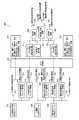
次に図5〜11を参照して、本実施形態に係る生体情報測定装置について説明する。図5は、本発明の第1実施形態に係る生体情報測定装置の概要を示すブロック図である。図6は、本発明の第1実施形態に係る生体情報測定装置のモニタ用心電図の出力例である。図7は、本発明の第1実施形態に係る生体情報測定装置の胸部の呼吸運動と腹部の呼吸運動の出力例である。図8は、本発明の第1実施形態に係る生体情報測定装置のモニタ用心電図に対する上背部の脈波と腰部の脈波の出力例である。図9は、本発明の第1実施形態に係る生体情報測定装置の上背部の脈波到達時間、腰部の脈波到達時間、上背部−腰部の脈波伝播時間、上背部−腰部の脈波伝播速度の出力例である。図10は、本発明の第1実施形態に係る生体情報測定装置の上背部の電極結合状態と腰部の電極結合状態の出力例である。図11は、本発明の第1実施形態に係る生体情報測定装置の胸部−腹部間の呼吸運動位相差の出力例である。(Explanation of biological information measuring device)
Next, the biological information measuring device according to the present embodiment will be described with reference to FIGS. 5 to 11. FIG. 5 is a block diagram showing an outline of the biological information measuring device according to the first embodiment of the present invention. FIG. 6 is an output example of an electrocardiogram for monitoring of the biological information measuring device according to the first embodiment of the present invention. FIG. 7 is an output example of the chest respiratory movement and the abdominal respiratory movement of the biological information measuring device according to the first embodiment of the present invention. FIG. 8 is an output example of a pulse wave in the upper back and a pulse wave in the lumbar region with respect to an electrocardiogram for monitoring of the biological information measuring device according to the first embodiment of the present invention. FIG. 9 shows the pulse wave arrival time of the upper back, the pulse wave arrival time of the lumbar region, the pulse wave velocity of the upper back-lumbar region, and the pulse wave of the upper back region-lumbar region of the biological information measuring device according to the first embodiment of the present invention. This is an output example of the propagation velocity. FIG. 10 is an output example of the electrode-coupled state of the upper back portion and the electrode-coupled state of the lumbar region of the biological information measuring device according to the first embodiment of the present invention. FIG. 11 is an output example of the respiratory movement phase difference between the chest and the abdomen of the biological information measuring device according to the first embodiment of the present invention.
初めに図5を参照して、本実施形態に係る生体情報測定装置200の全体概要について説明する。なお、以下では、生体情報測定装置200が計測もしくは算出する項目を、次のような番号を付して説明する。すなわち、(1)モニタ用心電図、(2)胸部の呼吸運動、(3)腹部の呼吸運動、(4)胸部−腹部間の呼吸運動位相差、(5)上背部の脈波、(6)腰部の脈波、(7)上背部の脈波到達時間、(8)腰部の脈波到達時間、(9)上背部−腰部間の脈波到達時間、(10)上背部−腰部間の脈波伝搬速度、(11)上背部の電極結合状態、(12)腰部の電極結合状態、とする。 First, with reference to FIG. 5, the overall outline of the biological
図2,3において説明したように、生体情報測定シート100によって検出された生体電気信号は、生体情報測定装置200の入力インタフェースとなる上背部結合状態計測モジュール210,心電図計測モジュール220、腰部結合状態計測モジュール230に入力される。 As described in FIGS. 2 and 3, the bioelectric signal detected by the biometric
上背部結合状態計測モジュール210からは、(11)上背部の電極結合状態211、胸部呼吸運動用フィルタ・増幅部212を介して(2)胸部の呼吸運動213、および、上背部脈波用フィルタ・増幅部214を介して(5)上背部の脈波215が検出・計測される。 From the upper back coupling
心電図計測モジュール220からは、(1)モニタ用心電図221、および、呼吸運動位相差用フィルタ・増幅部222を介して(4)胸部−腹部間の呼吸運動位相差223が検出・計測される。 From the
腰部結合状態計測モジュール230からは、腰部脈波用フィルタ・増幅部231を介して(6)腰部の脈波232、腹部呼吸運動用フィルタ・増幅部233を介して(3)腹部の呼吸運動234、および、(12)腰部の電極結合状態235が検出・計測される。 From the lumbar coupling
さらに、(11)上背部の電極結合状態211の信号はA/D変換器270を介してディジタル信号となり、A/D変換の算出例を示すブロック216のように離床/着床の判別、仰・腹臥位/側臥位の判別、結合安定度の判別、体位持続時間の係数算出等の処理を行うことができる。 Further, (11) the signal of the electrode coupling state 211 on the upper back becomes a digital signal via the A /
さらに、(5)上背部の脈波215、(1)モニタ用心電図221、(6)腰部の脈波232をA/D変換器270を介してディジタル化して、(5)上背部の脈波215と(6)腰部の脈波232からはピーク/ボトム/ゼロ公差時刻検出器217,236によってピーク/ボトム/ゼロ公差の時刻を検出し、(1)モニタ用心電図221からはR波時刻検出器224によってR波の発生時刻を検出する。なお、R波は心臓が収縮するときの電気の流れをいう。 Further, (5) upper back pulse wave 215, (1) monitor electrocardiogram 221 and (6) lumbar pulse wave 232 are digitized via an A /
上背部脈波のピーク/ボトム/ゼロ公差時刻とR波時刻とは時間差演算240によって発生時刻の差分をとることで(7)上背部の脈波到達時間241が算出される。同様に、腰部脈波のピーク/ボトム/ゼロ公差時刻とR波時刻とは時間差演算260によって発生時刻の差分をとることで(8)上背部の脈波到達時間261が算出される。 (7) The pulse wave arrival time 241 of the upper back is calculated by taking the difference between the peak / bottom / zero tolerance time of the upper back pulse wave and the R wave time by the
また、上背部脈波のピーク/ボトム/ゼロ公差時刻と腰部脈波のピーク/ボトム/ゼロ公差時刻とから時間差・速度演算250による演算を行うことで、(9)上背部−腰部間の脈波到達時間251、(10)上背部−腰部間の脈波伝播速度252が算出される。 Further, by performing the calculation by the time difference /
そして、(12)腰部の電極結合状態235の信号はA/D変換器270を介してディジタル信号となり、A/D変換の算出例を示すブロック237のように離床/着床の判別、仰・腹臥位/側臥位の判別、結合安定度の判別、体位持続時間の係数算出等の処理を行うことができる。 Then, (12) the signal of the
このように、本実施形態に係る生体情報測定装置200は、少なくとも(1)〜(12)の計測もしくは算出する項目を備えており、さらにこれらの検出信号についてディジタル変換を行うことで種々の判定・評価を可能としている。 As described above, the biological
例えば、体位(側臥位か仰臥位・腹臥位か)を判別して、閉塞型の睡眠時無呼吸症候群(SAS)が発症したときに本人が仰臥位/腹臥位で寝ていたら、警報を出して、病院の看護師や自宅にいる家族に体位変換を促すように報知することができる。また、閉塞型SASの患者は50%近くが夜間に不整脈を合併しているため、この不整脈異常は心電図計測によって検知できる。前記した体位変化の異常と不整脈との合併状況を検知することで、心疾患の治療を先に行うなどの治療方針を適切に設定することができる。 For example, if the body position (supine position or supine / prone position) is determined and the person is sleeping in the supine / prone position when obstructive sleep apnea syndrome (SAS) develops, an alarm is given. Can be issued to notify hospital nurses and family members at home to encourage them to change their positions. In addition, since nearly 50% of patients with obstructive SAS have arrhythmia at night, this arrhythmia abnormality can be detected by electrocardiogram measurement. By detecting the complication status of the above-mentioned abnormal position change and arrhythmia, it is possible to appropriately set a treatment policy such as first treating a heart disease.
次に、生体情報測定装置200が計測もしくは算出する項目の実施例を説明する。 Next, examples of items measured or calculated by the biological
((1)モニタ用心電図の出力例)
以下で説明する本実施形態における測定は、被験者である人体BODYが電極に直接接触することのない静電容量結合による接触を測定原理としていることから、人体BODYは、絶縁物としての薄地の布等を介して、生体情報測定シート100に密着され、被験者の体表面に生ずる生体電気信号の変化を検出している。((1) Output example of ECG for monitor)
Since the measurement in the present embodiment described below is based on the measurement principle of contact by capacitance coupling in which the human body BODY, which is the subject, does not come into direct contact with the electrodes, the human body BODY is a thin cloth as an insulating material. The change in the bioelectric signal generated on the body surface of the subject is detected by being brought into close contact with the biometric
二つの第2電極膜23、27から、心電図計測モジュール220へ入力された信号によって、二つの電極間の差動電圧(電位差)が測定されて、図6に示すモニタ用心電図が出力される。 The differential voltage (potential difference) between the two electrodes is measured by the signals input from the two
図6に示すように、本実施形態は、外部からの雑音や、シート下面からの漏れ電流を極力防止するように構成された生体情報測定シートを適用することで、安定した心電図を取得することができる As shown in FIG. 6, in the present embodiment, a stable electrocardiogram is acquired by applying a biometric information measurement sheet configured to prevent external noise and leakage current from the lower surface of the sheet as much as possible. Can
((2)胸部の呼吸運動、(3)腹部の呼吸運動の出力例)
上背部用電極膜13Aから上背部結合状態計測モジュール210へ、そして腰部用電極膜13Bから腰部結合状態計測モジュール230へ入力された信号は、フィルタによって呼吸成分が抽出され、増幅されて、図7に示す(2)胸部の呼吸運動と(3)腹部の呼吸運動が出力される。((2) Chest respiratory movement, (3) Abdominal respiratory movement output example)
The signals input from the upper
この実施例では、呼吸運動は呼吸運動を停止すると、出力振幅が0に近づき小さくなることから、呼吸停止区間を設けて、計測の妥当性を確認している。図7に示すように(2)胸部の呼吸運動、(3)腹部の呼吸運動とも、平常時の呼吸運動の区間と呼吸停止区間の出力振幅が0に近づく区間とが明確に現れている。 In this embodiment, when the respiratory movement is stopped, the output amplitude approaches 0 and becomes smaller. Therefore, a respiratory arrest section is provided to confirm the validity of the measurement. As shown in FIG. 7, in both (2) chest respiratory movement and (3) abdominal respiratory movement, a section of normal respiratory movement and a section in which the output amplitude of the respiratory arrest section approaches 0 clearly appear.
このように、本実施形態は、上背部結合状態計測モジュール210および腰部結合状態計測モジュール230からの信号をフィルタによって分離し、増幅することで良好な呼吸運動のチャートを出力することができる。 As described above, in this embodiment, the signals from the upper back coupling
((5)上背部の脈波、(6)腰部の脈波の出力例)
上背部用電極膜13Aから上背部結合状態計測モジュール210へ、そして腰部用電極膜13Bから腰部結合状態計測モジュール230へ入力された信号は、フィルタによって脈波成分が抽出され、増幅されて、図8に示す(5)上背部の脈波と(6)腰部の脈波が出力される。((5) Upper back pulse wave, (6) Lumbar pulse wave output example)
The signals input from the upper
図8に示す実施例では、図6に示した心臓の電気的な活動の様子である(1)モニタ用心電図の出力例も合わせて掲載した。図8に示すように(1)モニタ用心電図のR波発生に伴い、(5)上背部の脈波から(6)腰部の脈波へと波形が推移していることが分かる。 In the example shown in FIG. 8, the state of the electrical activity of the heart shown in FIG. 6 (1) An output example of an electrocardiogram for a monitor is also shown. As shown in FIG. 8, it can be seen that the waveform changes from (5) the pulse wave in the upper back to (6) the pulse wave in the lumbar region as the R wave of the monitor electrocardiogram is generated.
このように、本実施形態は、上背部結合状態計測モジュール210および腰部結合状態計測モジュール230からの信号をフィルタによって分離し、増幅することで良好な脈波のチャートを出力することができる。また、心電図と併記する処理をすることで、血流の異常を検出することができる。 As described above, in this embodiment, a good pulse wave chart can be output by separating and amplifying the signals from the upper back coupling
((7)上背部の脈波到達時間、(8)腰部の脈波到達時間、(9)上背部−腰部の脈波伝播時間、(10)上背部−腰部の脈波伝播速度の出力例)
図9は、図8の時間スケールを大きくして、(1)モニタ用心電図、(5)上背部脈波、(6)腰部脈波の関係を表している。(7) Upper back pulse wave arrival time, (8) Lumbar pulse wave arrival time, (9) Upper back-lumbar pulse wave velocity, (10) Upper back-lumbar pulse wave velocity output example )
FIG. 9 shows the relationship between (1) an electrocardiogram for a monitor, (5) an upper back pulse wave, and (6) a lumbar pulse wave by enlarging the time scale of FIG.
まず、(7)上背部の脈波到達時間は、(1)モニタ用心電図のR波発生時刻と上背部脈波信号のボトム値が発生する時刻との差分によって計測される。本実施例ではボトム値としているが、ピーク値発生時刻との差分でも良く、ピーク値発生時刻の場合には、取得した波形に基づいて、(7)上背部の脈波到達時間を算出することができる。 First, (7) the pulse wave arrival time of the upper back is measured by the difference between (1) the time when the R wave is generated on the monitor electrocardiogram and the time when the bottom value of the upper back pulse wave signal is generated. In this embodiment, the bottom value is used, but the difference from the peak value occurrence time may be used. In the case of the peak value occurrence time, (7) the pulse wave arrival time of the upper back is calculated based on the acquired waveform. Can be done.
次に、(8)腰部の脈波到達時間も、(7)上背部の脈波到達時間と同様に、(1)モニタ用心電図のR波発生時刻と要部脈波信号のボトム値が発生する時刻との差分によって計測される。本実施例ではボトム値としているが、ピーク値発生時刻との差分でも良く、ピーク値発生時刻の場合には、取得した波形に基づいて、(8)腰部の脈波到達時間を算出することができる。 Next, (8) the pulse wave arrival time in the lumbar region is similar to (7) the pulse wave arrival time in the upper back, and (1) the R wave generation time of the monitor electrocardiogram and the bottom value of the main pulse wave signal are generated. It is measured by the difference from the time of day. In this embodiment, the bottom value is used, but the difference from the peak value occurrence time may be used. In the case of the peak value occurrence time, (8) the pulse wave arrival time of the lumbar region can be calculated based on the acquired waveform. it can.
そして、(9)上背部−腰部の脈波伝播時間については、(5)上背部脈波と(6)腰部脈波の近接するボトム値が発生する時刻の差分によって表され、(10)上背部−腰部の脈波伝播速度については、(9)上背部−腰部の脈波伝播時間を電極間の距離で除することで算出することができる。 The (9) upper back-lumbar pulse wave velocity is represented by the difference between (5) the time at which the upper back pulse wave and (6) the adjacent bottom value of the lumbar pulse wave occur, and (10) above. The pulse wave velocity between the back and the lumbar region can be calculated by dividing (9) the pulse wave velocity between the upper back and the lumbar region by the distance between the electrodes.
このように、本実施形態では、互いに影響を受けず、外部からの雑音も抑制された脈波と心電図を同時に測定することができることから、血流の異常等を数値として算出することができるため、例えば、判定・評価等のしきい値を設けることで、異常検出の報知システムを容易に構築することができる。 As described above, in the present embodiment, since the pulse wave and the electrocardiogram, which are not affected by each other and the noise from the outside is suppressed, can be measured at the same time, the abnormality of blood flow and the like can be calculated as a numerical value. For example, by setting a threshold value for determination / evaluation, an abnormality detection notification system can be easily constructed.
((11)上背部の電極結合状態、(12)腰部の電極結合状態の出力例)
上背部用電極膜13Aから上背部結合状態計測モジュール210へ、そして腰部用電極膜13Bから腰部結合状態計測モジュール230へ入力された信号によって、図10に示す(11)上背部の電極結合状態、(12)腰部の電極結合状態が出力される。((11) Output example of the electrode-coupled state of the upper back and (12) Electrode-coupled state of the waist)
According to the signals input from the upper
図10を参照すると、(11)上背部の電極結合状態は、人体BODYが生体情報測定シート100上に臥位の状態のときには低い電位となっており、離床したときには電位が上昇する。そして、人体BODYが寝返り動作等によって生体情報測定シート100上での動きがあったときには電極の結合状態が変化するため、電位にも変化が現れる。 Referring to FIG. 10, (11) the electrode coupling state of the upper back has a low potential when the human body BODY is in the lying position on the biological
次に、(12)腰部の電極結合状態を見ると、前記した(11)上背部の電極結合状態と同様な電位の変化が見られるが、仰臥位と側臥位との電極結合状態の違いから出力される電位に差が生じ、仰臥位に比べて側臥位の方が高い電位となる。 Next, looking at (12) the electrode-coupled state of the lumbar region, the same potential change as (11) the electrode-coupled state of the upper back can be seen, but due to the difference in the electrode-coupled state between the supine position and the lateral decubitus position. There is a difference in the output potential, and the potential is higher in the lateral decubitus position than in the supine position.
そして、(11)上背部の電極結合状態と(12)腰部の電極結合状態の出力を合わせて観測することで、被験者の人体BODYの着床(仰臥位か側臥位)、寝返り、離床等の状況を把握することができる。 Then, by observing the output of (11) the electrode-coupled state of the upper back and (12) the electrode-coupled state of the lumbar region together, the subject's human body BODY can be implanted (supine or laterally), turned over, get out of bed, etc. You can grasp the situation.
このように、本実施形態では、被験者の就寝状態等を上背部と腰部の電極結合状態を出力することにより観測することができるため、異常や徘徊等について早期に検出することができる。例えば、寝返りの頻度を算出して、所定のしきい値よりも少ない場合には、看護師等に報知するシステムを構築することも可能であり、細やかな介護を実現することができる。 As described above, in the present embodiment, since the sleeping state of the subject can be observed by outputting the electrode coupling state of the upper back and the lumbar region, abnormalities, wandering, etc. can be detected at an early stage. For example, it is possible to construct a system for calculating the frequency of turning over and notifying a nurse or the like when the frequency is less than a predetermined threshold value, and it is possible to realize detailed nursing care.
((4)胸部−腹部間の呼吸運動位相差の出力例)
心電図計測モジュール220からは、呼吸運動位相差用フィルタ・増幅部222を介して(4)胸部−腹部間の呼吸運動位相差が出力される。なお、(4)胸部−腹部間の呼吸運動位相差は、(2)胸部の呼吸運動、(3)腹部の呼吸運動の情報からディジタル信号処理で算出して出力することもできるが、図11に示す本実施例のようにアナログ信号として出力することで観測者にとって見やすいチャートとすることができる。((4) Output example of respiratory movement phase difference between chest and abdomen)
From the
(4)胸部−腹部間の呼吸運動位相差の情報は睡眠時無呼吸症候群(SAS)の種類の鑑別に利用できる。SASには閉そく型と中枢型、混合型があり、治療方針が異なることからこれらの医師による鑑別が必要となる。また、SASの閉そく型と混合型では、胸部の呼吸運動と腹部の呼吸運動が逆相になることが知られている。 (4) Information on the respiratory movement phase difference between the chest and abdomen can be used to distinguish the type of sleep apnea syndrome (SAS). There are closed type, central type, and mixed type of SAS, and since the treatment policy is different, it is necessary to distinguish them by doctors. In addition, it is known that the respiratory movements of the chest and the respiratory movements of the abdomen are out of phase in the closed type and the mixed type of SAS.
図11において、右側の「胸部−腹部逆相 呼吸運動(閉そく模擬)指示期間」は、閉そく型睡眠時無呼吸症候群を模擬して、被験者が意図的に気道を閉そくし、かつ、呼吸運動を行った場合の出力結果となる。 In FIG. 11, the “chest-abdominal reverse phase respiratory movement (simulation of closure) instruction period” on the right side simulates the apnea syndrome during sleep apnea, and the subject intentionally closes the airway and performs respiratory movement. It will be the output result when it is done.
図11を参照して、通常の呼吸運動(胸部−腹部同相 呼吸運動指示期間)と、閉そく模擬(腹部−右側の胸部−腹部逆相 呼吸運動指示期間)とを比較すると、振幅に大きな差異を生じており、異常を容易に検出することができる。 With reference to FIG. 11, when comparing normal respiratory movement (chest-abdominal in-phase respiratory movement instruction period) and constriction simulation (abdomen-right chest-abdominal reverse-phase respiratory movement instruction period), there is a large difference in amplitude. It has occurred and the abnormality can be easily detected.
閉塞型SASの患者では50%近くが夜間に不整脈を合併する。不整脈の合併は治療方針に影響し(心疾患の治療を先に行うなど)、不整脈は心電図計測でのみ検知でき、閉塞型のSAS患者に対しては夜間に心電図を計測することが効果的となる。 Nearly 50% of patients with obstructive SAS have arrhythmias at night. The complication of arrhythmia affects the treatment policy (such as treatment of heart disease first), and arrhythmia can be detected only by electrocardiogram measurement, and it is effective to measure electrocardiogram at night for obstructive SAS patients. Become.
図11に示す本実施例では、閉塞型のSASかどうかを、腹部と胸部の呼吸運動(の位相差)の計測にて容易に判定できることから、(4)胸部−腹部間の呼吸運動位相差の出力と(1)モニタ用心電図の出力と、を同時計測できる本実施形態は、閉塞型SASの検知と検知後の治療方針の決定に有用となる。 In this embodiment shown in FIG. 11, it can be easily determined whether or not the SAS is obstructive by measuring the respiratory movement (phase difference) between the abdomen and the chest. Therefore, (4) the respiratory movement phase difference between the chest and the abdomen. This embodiment, which can simultaneously measure the output of (1) the output of the electrocardiogram for monitoring, is useful for detecting the obstructive SAS and determining the treatment policy after the detection.
さらに軽度の閉塞型SASでは、側臥位をとることでAHI(睡眠時無呼吸の重症度の指標)が50%程度の症例で改善することから、(4)胸部−腹部間の呼吸運動位相差の出力と(11)上背部の電極結合状態、(12)腰部の電極結合状態の出力と、を同時計測することで、閉塞型SASが発症したときに本人が仰臥位/腹臥位で寝ていたら、病院の看護師や自宅の家族に向けて警報を出して、被験者の体位変換を促すシステムを構築することもできる。 In milder obstructive SAS, AHI (an index of the severity of sleep apnea) improves in about 50% of cases by taking the lateral decubitus position. Therefore, (4) Respiratory movement phase difference between chest and abdomen By simultaneously measuring the output of (11) the electrode-coupled state of the upper back and (12) the output of the electrode-coupled state of the waist, the person sleeps in the supine / prone position when obstructive SAS develops. If so, it is possible to build a system that prompts the subject to change his / her position by issuing an alarm to the nurse in the hospital or his / her family at home.
また、(4)胸部−腹部間の呼吸運動位相差の出力情報からAHIを算出できるため、体位によるAHIへの影響の評価を行うことができる。 Further, since (4) AHI can be calculated from the output information of the respiratory movement phase difference between the chest and the abdomen, the influence of the body position on AHI can be evaluated.
このように、本実施形態では、(4)胸部−腹部間の呼吸運動位相差の情報だけで無く、心電図や体位の状態等と併せて観測することで、看護師等に報知するシステムを構築することも可能であり、細やかな介護を実現することができる。 As described above, in the present embodiment, (4) a system for notifying nurses and the like is constructed by observing not only the information on the respiratory movement phase difference between the chest and the abdomen but also the electrocardiogram and the state of the body position. It is also possible to provide detailed nursing care.
(第2実施形態)
次に、図12を参照して、本発明の第2実施形態について説明する。図12は、本発明の第2実施形態に係る生体情報測定シートの一例の説明図である。本発明の第2実施形態は、計測時の同相雑音を抑制するための構成を第1実施形態に付加した実施形態であり、その他の構成については第1実施形態と同じであるため、以下の説明において、第1実施形態と重複する構成についてはその説明を省略する。(Second Embodiment)
Next, a second embodiment of the present invention will be described with reference to FIG. FIG. 12 is an explanatory diagram of an example of a biological information measurement sheet according to a second embodiment of the present invention. The second embodiment of the present invention is an embodiment in which a configuration for suppressing in-phase noise at the time of measurement is added to the first embodiment, and other configurations are the same as those of the first embodiment. In the description, the description of the configuration overlapping with the first embodiment will be omitted.
図12を参照すると、本実施形態に係る生体情報測定シート300は、第1実施形態で説明した生体情報測定シート100の二つの第2生体情報測定部20、20の間の第2絶縁膜14の上にさらに第3電極膜61を載置し、この第3電極膜61を囲うように第2絶縁膜14の上に第5絶縁膜71を載置している。第3電極膜61とバッファ31,41はDSG(ドリブン・シート・グラウンド)回路75を介して電気的に繋がれている。ここで、DSG回路75の配置は二つの第2生体情報測定部20、20の間の第2電極膜14の上に限定されることはない。 Referring to FIG. 12, the biometric
DSG回路75は、心電図計測において信号ラインと接地間にノイズ源が存在するとき、信号ラインに伝達される同相雑音を減少させるために用いられるフィードバック回路である。図12の矢印Xで示すように、バッファ31,41からの信号がDSG回路75に送られる。これらの信号はDSG回路75にて加算されて、第3電極膜61へ矢印Yで示すように負帰還されている。 The
非接触で心電計側を行う場合、そのインピーダンスは大きく減じられないことから取得された信号を飽和させるほど、同相雑音(コモンモードノイズ)が高くなるときがある。この高い同相雑音は、ローパスフィルターやハイカットオフフィルターを付加しても減じることは難しく、心電計側をする上で障害となる。しかしながら、本実施形態によれば、DSG回路75を第3電極膜61とバッファ31,41との間に配して、第3電極膜61をフィードバック電極とすることで、心電図計測のための増幅器に入力される同相信号の位相を反転させることでき、同相雑音を低減することができる。 When the electrocardiograph side is operated in a non-contact manner, the impedance is not significantly reduced. Therefore, the common mode noise may increase as the acquired signal is saturated. This high common mode noise is difficult to reduce even if a low-pass filter or a high-cut-off filter is added, which is an obstacle to the electrocardiograph side. However, according to the present embodiment, the
ここで、バッファ31,41は、入力インピーダンスが高く利得が1であるボルテージフォロアを適用することが好ましい。ボルテージフォロアは、アンプの入出力インピーダンスを利用してインピーダンス変換を行う回路である。例えば、高いインピーダンスのセンサから出力されている電圧を集録するときに、入力側と出力側で分圧・分流が生じて正しい電圧を取得できないことがある。このような場合にボルテージフォロア回路を使用することで、入力回路のインピーダンスを抑えることができる。 Here, it is preferable to apply a voltage follower having a high input impedance and a gain of 1 to the
また、本実施形態では第2絶縁膜14の上に第3電極膜61を囲うようにさらに第5絶縁膜71を載置する構成としているが、ノイズ等を抑制する効果は多少低下するが、第5絶縁膜71を載置せずに、第2絶縁膜14の上に直接第3電極膜61のみを載置する構成とすることもできる。 Further, in the present embodiment, the fifth insulating
次に図13,14を参照して、本実施形態の構成を適用した一例について説明する。図13は、本実施形態に係る生体情報測定装置のモニタ用心電図にて計測波形の出力例である。図14は、本実施形態に係る生体情報測定装置のモニタ用心電図の出力例である。 Next, an example in which the configuration of the present embodiment is applied will be described with reference to FIGS. 13 and 14. FIG. 13 is an output example of the measurement waveform in the monitor electrocardiogram of the biological information measuring device according to the present embodiment. FIG. 14 is an output example of an electrocardiogram for monitoring of the biological information measuring device according to the present embodiment.
図13は、本実施形態のDSG回路75を付加した場合における同相雑音に対する影響を確認した結果を、DSG回路75が無い第1実施形態の結果と比較したものである。以下ではDSG回路75が付加された本実施形態を実施例、DSG回路75を有さない実施形態を参考例として説明する。 FIG. 13 compares the result of confirming the influence on the common mode noise when the
図13は、モニタ用心電図にて計測波形の出力について、心電図の波形が基線(一般にP波の始まりから次の始まりまでを結んだ線をいう)へ復帰する時間について、(A)参考例と(B)実施例とを比較したものである。 FIG. 13 shows the output of the measured waveform on the monitor electrocardiogram, and the time for the electrocardiogram waveform to return to the baseline (generally, the line connecting the start of the P wave to the next start) with reference to (A) a reference example. (B) This is a comparison with the examples.
試験は、3名の被験者の両肩が寝具についたタイミングSから、安定時の基線電圧の±5%に基線が収まった時間Eを基線復帰時間として評価した。図13の縦軸方向の破線は、SとEの位置を示しており、SとEとの間隔が基線復帰時間となる。 In the test, the time E during which the baseline fell within ± 5% of the baseline voltage at the time of stabilization was evaluated as the baseline return time from the timing S when both shoulders of the three subjects were attached to the bedding. The broken line in the vertical axis direction of FIG. 13 indicates the positions of S and E, and the distance between S and E is the baseline return time.
図13に示すように、(A)参考例と(B)実施例とを比べると、明らかに(B)実施例の方が、基線復帰時間が短縮されている。3名の被験者ごとに複数回試験を行って、基線復帰時間をまとめた結果は、以下の通りである。なお、計測時間内に基線が復帰しなかった実験は対象外とした。
第1被験者:参考例(15.94sec)、実施例(13.91sec)、
第2被験者:参考例(22.61sec)、実施例(14.11sec)、
第3被験者:参考例( 8.24sec)、実施例( 6.84sec)、As shown in FIG. 13, when (A) Reference Example and (B) Example are compared, it is clear that (B) Example has a shorter baseline return time. The results of conducting the test multiple times for each of the three subjects and summarizing the baseline return time are as follows. Experiments in which the baseline did not return within the measurement time were excluded.
First subject: Reference example (15.94 sec), Example (13.91 sec),
Second subject: Reference example (22.61 sec), Example (14.11 sec),
Third subject: Reference example (8.24 sec), Example (6.84 sec),
このように、それぞれの被験者においての平均基線復帰時間は、DSG回路導入後のシステムにより短縮されていることが確認された。一つ一つの計測結果を見ると、第1、第2被験者は、全ての実験結果において、DSG回路の導入により、基線復帰時間が短縮された。しかし、第3被験者は、何回かの計測において、DSG回路導入後の基線復帰時間が導入前より延長するという結果となったが、平均としては実施例の基線復帰時間は短縮された。 In this way, it was confirmed that the average baseline return time in each subject was shortened by the system after the introduction of the DSG circuit. Looking at the measurement results one by one, in all the experimental results, the introduction of the DSG circuit shortened the baseline return time for the first and second subjects. However, in some measurements, the third subject found that the baseline return time after the introduction of the DSG circuit was longer than that before the introduction, but on average, the baseline return time in the examples was shortened.
次に図14を参照すると、DSG回路75と第3電極膜61の間にオン/オフスイッチを設けて(図示せず)、このスイッチを切り替えたときの心電図計測波形を示している。すなわち、図13の説明において、オンはDSG回路が付加された実施例、オフはDSG回路を有さない参考例に相当する。 Next, referring to FIG. 14, an on / off switch is provided between the
図14(A)の上段に示した心電図生波形を見ると、スイッチオフからオンへ切り替え後に、大幅に同相雑音が低減している。次に図14(A)の下段に示した移動平均波形を見ると、スイッチ切り替え前後でほぼ波形に変化は現れていない。このことから本実施形態に係る実施例が、同相雑音のみの低減を可能にしていることが示されている。 Looking at the electrocardiogram raw waveform shown in the upper part of FIG. 14A, the common mode noise is significantly reduced after the switch is switched from off to on. Next, looking at the moving average waveform shown in the lower part of FIG. 14A, there is almost no change in the waveform before and after the switch is switched. From this, it is shown that the embodiment according to the present embodiment makes it possible to reduce only the common mode noise.
さらに、図14(B)は、試験中に同相雑音の電圧値制御が上手くいかず、飽和してしまった際の波形であり、(A)と比べてオフ時の同相雑音が大きな状態となっている。スイッチオフの際は、図14(B)の下段に示した移動平均波形である心電図が確認できないのに対し、スイッチオン後は、同相雑音が低減され、心電図を確認することができている。 Further, FIG. 14B shows a waveform when the voltage value control of the common-mode noise does not go well during the test and the common-mode noise becomes saturated, and the common-mode noise at the time of off becomes larger than that of (A). ing. When the switch is turned off, the electrocardiogram which is the moving average waveform shown in the lower part of FIG. 14B cannot be confirmed, whereas after the switch is turned on, the in-phase noise is reduced and the electrocardiogram can be confirmed.
治療・手術後には患者の体温回復や冬季の加温用に電気毛布が使用される。しかしながら,電気毛布は発熱させるため,心電図波形に商用電源とその高調波からなる同相雑音が重畳して、波形が歪むことや信号雑音比(SNR)の低下の問題が生じていた。この状況は、図13の参考例や、図14のオフ時の状態となる。
しかしながら、本実施形態に係る生体情報測定シート300によればDSG回路を付加することで、同相雑音を低減することができ、良好な心電計側を実現できる。After treatment and surgery, electric blankets are used to restore the patient's body temperature and warm the patient in winter. However, since the electric blanket generates heat, in-phase noise consisting of a commercial power supply and its harmonics is superimposed on the electrocardiogram waveform, which causes problems such as distortion of the waveform and reduction of the signal-to-noise ratio (SNR). This situation is the reference example of FIG. 13 and the off state of FIG.
However, according to the biometric
以上で説明を終えるが、本発明の態様は上記実施形態に限られるものではなく、例えば、図5に示すようにA/D変換を行うことで、時間を基準とした種々のディジタル信号処理を行うことができるため、各出力値との関連性の解析を通じて、新たな指標や、その指標に基づく報知システム等の構築に応用することもできる。 Although the description is finished above, the embodiment of the present invention is not limited to the above embodiment. For example, by performing A / D conversion as shown in FIG. 5, various digital signal processing based on time can be performed. Therefore, it can be applied to the construction of a new index or a notification system based on the index through the analysis of the relationship with each output value.
また、静電容量結合は、汗や失禁等の水分等が介在することによっても変化を計測することができる。このような水分量による静電容量結合の変化は一例であって、本発明は、実施行為の蓄積によって、新たな状態量に係る情報を取得することができる。 In addition, the change in the capacitance coupling can be measured by the intervention of moisture such as sweat and incontinence. Such a change in capacitance coupling due to the amount of water is an example, and the present invention can acquire information relating to a new amount of state by accumulating actions.
10・・・第1生体情報測定部
11・・・第1絶縁膜
12・・・グランド電極膜
13・・・第1電極膜
13A・・・上背部用電極膜
13B・・・腰部用電極膜
14・・・第2絶縁膜
20・・・第2生体情報測定部
21,25・・・導電性シールド膜
22,26・・・第3絶縁膜
23,27・・・第2電極膜
31,41・・・バッファ
32,42・・・抵抗
51,52・・・第4絶縁膜
61・・・第3電極膜
71・・・第5絶縁膜
75・・・ドリブン・シート・グラウンド回路(DSG回路)
100、300・・・生体情報測定シート
200・・・生体情報測定装置
210・・・上背部結合状態計測モジュール
211・・・上背部の電極結合状態
212・・・胸部呼吸運動用フィルタ・増幅部
213・・・胸部の呼吸運動
214・・・上背部脈波用フィルタ・増幅部
215・・・上背部の脈波
216・・・A/D変換の算出例
217・・・ピーク/ボトム/ゼロ公差時刻検出器
220・・・心電図計測モジュール
221・・・モニタ用心電図
222・・・呼吸運動位相差用フィルタ・増幅部
223・・・胸部−腹部間の呼吸運動位相差
224・・・R波時刻検出器
230・・・腰部結合状態計測モジュール
231・・・腰部脈波用フィルタ・増幅部
232・・・腰部の脈波
233・・・腹部呼吸運動用フィルタ・増幅部
234・・・腹部の呼吸運動
235・・・腰部の電極結合状態
236・・・ピーク/ボトム/ゼロ公差時刻検出器
237・・・A/D変換の算出例
240・・・時間差演算
241・・・上背部の脈波到達時間
250・・・時間差・速度演算
251・・・上背部−腰部間の脈波伝播時間
252・・・上背部−腰部間の脈波伝播速度
260・・・時間差演算
261・・・腰部の脈波到達時間
270・・・A/D変換器
10 ... 1st biological
100, 300 ... Biological
Claims (16)
Translated fromJapanese前記延在方向の先端部および終端部付近に、前記延在方向と直交するように前記第1絶縁膜に載置された帯状の二つの第1電極膜、
前記第1絶縁膜の前記二つの第1電極膜の間に載置され、グランドと繋がったシート状のグランド電極膜、および、
前記グランド電極膜の先端側と終端側を一部露出させるように前記グランド電極膜に載置されたシート状の第2絶縁膜、からなる第1生体情報測定部と、
前記第2絶縁膜の前記延在方向と直交する帯状の導電性シールド膜、
前記導電性シールド膜の先端側と終端側を一部露出させるように前記導電性シールド膜に載置された帯状の第3絶縁膜、および
前記第3絶縁膜の先端側と終端側を一部露出させるように前記第3絶縁膜に載置された帯状の第2電極膜、からなる第2生体情報測定部と、を備え、
前記第2生体情報測定部が、前記第2絶縁膜上の前記延在方向に並行して二以上載置されていることを特徴とする生体情報測定シート。A sheet-like first insulating film extending from the shoulder to the buttocks of the human body,
Two strip-shaped first electrode films placed on the first insulating film so as to be orthogonal to the extending direction near the tip and the end in the extending direction.
A sheet-shaped ground electrode film placed between the two first electrode films of the first insulating film and connected to the ground, and a ground electrode film, and
A first biometric information measuring unit composed of a sheet-shaped second insulating film placed on the ground electrode film so as to partially expose the front end side and the end side of the ground electrode film.
A strip-shaped conductive shield film orthogonal to the extending direction of the second insulating film,
A band-shaped third insulating film placed on the conductive shield film so as to partially expose the tip side and the terminal side of the conductive shield film, and a part of the tip side and the terminal side of the third insulating film. A second biological information measuring unit including a band-shaped second electrode film placed on the third insulating film so as to be exposed is provided.
A biological information measurement sheet characterized in that two or more of the second biological information measuring units are placed in parallel on the second insulating film in the extending direction.
前記第1生体情報測定部の前記第1電極膜と前記グランド電極膜もしくは前記グランドとから検出された生体情報によって、人体の離床、体動、呼吸に関する情報を取得する第1生体情報取得部と、
二以上の前記第2生体情報測定部の前記第2電極膜と前記導電性シールド膜とから検出された生体情報によって、心電図に関する情報を取得する第2生体情報取得部と、を備えた生体情報測定装置。The biological information measurement sheet according to any one of claims 1 to 5,
With the first biological information acquisition unit that acquires information on getting out of bed, body movement, and respiration of the human body by the biological information detected from the first electrode film and the ground electrode film or the ground of the first biological information measurement unit. ,
Biological information including a second biometric information acquisition unit that acquires information on an electrocardiogram based on biometric information detected from the second electrode film and the conductive shield film of the second or more second biometric information measuring unit. measuring device.
前記第2電極膜ごとに分離された前記呼吸成分を算出し、
それぞれの前記呼吸成分の位相差を算出することを特徴とする請求項6に記載の生体情報測定装置。A separation filter for separating two or more electrocardiographic bioelectric signals input from the second electrode membrane to the second biometric information acquisition unit via a buffer into the electrocardiogram component and the respiratory component is provided.
The respiratory component separated for each of the second electrode membranes was calculated.
The biological information measuring device according to claim 6, wherein the phase difference of each of the respiratory components is calculated.
該第3電極膜を囲うように前記第2絶縁膜に第5絶縁膜を載置し、
該第3電極膜と前記バッファとがドリブン・シート・グラウンド回路を介して電気的に繋がれていることを特徴とする請求項7または8に記載の生体情報測定装置。A third electrode film is placed on the second insulating film, and the third electrode film is placed on the second insulating film.
A fifth insulating film is placed on the second insulating film so as to surround the third electrode film.
The biometric information measuring apparatus according to claim 7 or 8, wherein the third electrode film and the buffer are electrically connected via a driven sheet ground circuit.
分離された前記胸部呼吸成分と前記上背部脈波成分とから、胸部呼吸運動信号と上背部脈波信号を計測することを特徴とする請求項6または7に記載の生体情報測定装置。For the upper back position, which is the first electrode film and is input from the upper back electrode film placed on the first insulating film so as to be orthogonal to the extending direction at the tip of the extending direction. A separation filter for separating the thoracic respiratory component and the upper back pulse wave component from the electric signal and the ground electric signal input from the ground electrode membrane or the ground is provided.
The biometric information measuring device according to claim 6 or 7, wherein a chest respiratory movement signal and an upper back pulse wave signal are measured from the separated chest respiratory component and the upper back pulse wave component.
分離された前記腹部呼吸成分と前記腰部脈波成分とから、腹部呼吸運動信号と腰部脈波信号を計測することを特徴とする請求項6または7に記載の生体情報測定装置。An electrical signal for lumbar position input from a lumbar electrode film placed on the first insulating film so as to be orthogonal to the extending direction at the end of the first electrode film in the extending direction. And a separation filter for separating the abdominal respiratory component and the lumbar pulse wave component from the ground electrode membrane or the ground electric signal input from the ground.
The biometric information measuring device according to claim 6 or 7, wherein the abdominal respiratory movement signal and the lumbar pulse wave signal are measured from the separated abdominal respiratory component and the lumbar pulse wave component.
According to the upper back pulse wave arrival time described in claim 13 and the lumbar pulse wave arrival time described in claim 15, the pulse wave velocity between the upper back and the lumbar region and between the upper back and the lumbar region. A biological information measuring device characterized by calculating the pulse wave velocity of the body.
Applications Claiming Priority (3)
| Application Number | Priority Date | Filing Date | Title |
|---|---|---|---|
| JP2016158892 | 2016-08-12 | ||
| JP2016158892 | 2016-08-12 | ||
| PCT/JP2017/028738WO2018030393A1 (en) | 2016-08-12 | 2017-08-08 | Vital sign measurement sheet and vital sign measurement device |
Publications (2)
| Publication Number | Publication Date |
|---|---|
| JPWO2018030393A1 JPWO2018030393A1 (en) | 2019-06-13 |
| JP6883341B2true JP6883341B2 (en) | 2021-06-09 |
Family
ID=61162289
Family Applications (1)
| Application Number | Title | Priority Date | Filing Date |
|---|---|---|---|
| JP2018533491AActiveJP6883341B2 (en) | 2016-08-12 | 2017-08-08 | Biometric information measurement sheet and biometric information measuring device |
Country Status (2)
| Country | Link |
|---|---|
| JP (1) | JP6883341B2 (en) |
| WO (1) | WO2018030393A1 (en) |
Families Citing this family (5)
| Publication number | Priority date | Publication date | Assignee | Title |
|---|---|---|---|---|
| JP7080482B2 (en)* | 2018-07-25 | 2022-06-06 | 学校法人東京電機大学 | Circuit board |
| JP7425546B2 (en)* | 2019-06-05 | 2024-01-31 | 株式会社東海理化電機製作所 | Vehicle electrocardiogram detection device |
| DE102019216119B4 (en)* | 2019-10-18 | 2024-06-06 | Inomed Medizintechnik Gmbh | Bipolar mapping suction cup |
| CN113440347A (en)* | 2021-01-11 | 2021-09-28 | 宁波市第九医院 | Electric standing bed integrating non-contact cardiopulmonary function real-time monitoring and assessment |
| JP7667013B2 (en)* | 2021-08-02 | 2025-04-22 | マクセル株式会社 | Electrocardiogram signal analyzer |
Family Cites Families (4)
| Publication number | Priority date | Publication date | Assignee | Title |
|---|---|---|---|---|
| JP2010194137A (en)* | 2009-02-26 | 2010-09-09 | Ritsumeikan | Noncontact electrocardiographic sensor |
| JP5820600B2 (en)* | 2011-03-30 | 2015-11-24 | 学校法人東京電機大学 | Biological signal measuring device, biological signal measuring bed, and biological signal measuring method |
| JP6212814B2 (en)* | 2013-05-21 | 2017-10-18 | 国立研究開発法人科学技術振興機構 | Multi-point probe, electronic contact sheet constituting the same, multi-point probe array, and method for manufacturing multi-point probe |
| US9808202B2 (en)* | 2014-11-28 | 2017-11-07 | Shenzhen Novocare Medical Devices Co, INC | Mattress for measuring physiological parameters of heart |
- 2017
- 2017-08-08JPJP2018533491Apatent/JP6883341B2/enactiveActive
- 2017-08-08WOPCT/JP2017/028738patent/WO2018030393A1/ennot_activeCeased
Also Published As
| Publication number | Publication date |
|---|---|
| JPWO2018030393A1 (en) | 2019-06-13 |
| WO2018030393A1 (en) | 2018-02-15 |
Similar Documents
| Publication | Publication Date | Title |
|---|---|---|
| JP6883341B2 (en) | Biometric information measurement sheet and biometric information measuring device | |
| Takano et al. | Noncontact in-bed measurements of physiological and behavioral signals using an integrated fabric-sheet sensing scheme | |
| KR102687254B1 (en) | Sleep state measurement device and method, phase coherence calculation device, biological vibration signal measurement device, stress state measurement device, sleep state measurement device, and heart rate waveform extraction method | |
| CN107743378B (en) | Non-invasive detection of backflow of urine | |
| KR100736721B1 (en) | Electric non-contact apparatus and method for taking electrocardiograms | |
| CN109171702A (en) | A kind of measuring device and measurement method of contactless electrocardiosignal | |
| CN108245144A (en) | A kind of contactless monitoring mattress and monitor system based on Multi-sensor Fusion | |
| EP2429390A1 (en) | System and methods using flexible capacitive electrodes for measuring biosignals | |
| Peng et al. | Flexible electrodes-based smart mattress for monitoring physiological signals of heart and autonomic nerves in a non-contact way | |
| Wu et al. | Contactless and continuous monitoring of heart electric activities through clothes on a sleeping bed | |
| JP2000000214A (en) | Sleeping monitor device | |
| US20150182131A1 (en) | Neonatal health care monitoring system | |
| CN102697488B (en) | Unrestrained sleep physiological information detection device | |
| Młyńczak et al. | Impedance pneumography: Is it possible? | |
| Sadleir et al. | Detection and quantification of intraperitoneal fluid using electrical impedance tomography | |
| Sel et al. | Measurement of chest physiological signals using wirelessly coupled bio-impedance patches | |
| JP5820600B2 (en) | Biological signal measuring device, biological signal measuring bed, and biological signal measuring method | |
| CN105640524A (en) | Device for monitoring breath and heartbeat during sleeping | |
| Liu et al. | Flexible non-contact electrodes for bioelectrical signal monitoring | |
| Lim et al. | Capacitive driven-right-leg grounding in indirect-contact ECG measurement | |
| WO2007094464A1 (en) | Cardiopulmonary function measuring instrument | |
| JP2005253924A (en) | Sleep apnea examining and alarming apparatus | |
| Ueno et al. | Unconstrained monitoring of ECG and respiratory variation in infants with underwear during sleep using a bed-sheet electrode unit | |
| JP2021041026A (en) | Biomedical measurement apparatus | |
| Ishida et al. | Electrocardiogram measurement during sleep with wearing clothes using capacitively-coupled electrodes |
Legal Events
| Date | Code | Title | Description |
|---|---|---|---|
| A521 | Request for written amendment filed | Free format text:JAPANESE INTERMEDIATE CODE: A821 Effective date:20190201 | |
| A621 | Written request for application examination | Free format text:JAPANESE INTERMEDIATE CODE: A621 Effective date:20200807 | |
| TRDD | Decision of grant or rejection written | ||
| A01 | Written decision to grant a patent or to grant a registration (utility model) | Free format text:JAPANESE INTERMEDIATE CODE: A01 Effective date:20210330 | |
| A61 | First payment of annual fees (during grant procedure) | Free format text:JAPANESE INTERMEDIATE CODE: A61 Effective date:20210427 | |
| R150 | Certificate of patent or registration of utility model | Ref document number:6883341 Country of ref document:JP Free format text:JAPANESE INTERMEDIATE CODE: R150 | |
| R250 | Receipt of annual fees | Free format text:JAPANESE INTERMEDIATE CODE: R250 | |
| R250 | Receipt of annual fees | Free format text:JAPANESE INTERMEDIATE CODE: R250 |