JP6880473B2 - Beverage product manufacturing method - Google Patents
Beverage product manufacturing methodDownload PDFInfo
- Publication number
- JP6880473B2 JP6880473B2JP2016125905AJP2016125905AJP6880473B2JP 6880473 B2JP6880473 B2JP 6880473B2JP 2016125905 AJP2016125905 AJP 2016125905AJP 2016125905 AJP2016125905 AJP 2016125905AJP 6880473 B2JP6880473 B2JP 6880473B2
- Authority
- JP
- Japan
- Prior art keywords
- preform
- plastic member
- container
- composite
- resin
- Prior art date
- Legal status (The legal status is an assumption and is not a legal conclusion. Google has not performed a legal analysis and makes no representation as to the accuracy of the status listed.)
- Active
Links
Images


Landscapes
- Packging For Living Organisms, Food Or Medicinal Products That Are Sensitive To Environmental Conditiond (AREA)
- Filling Of Jars Or Cans And Processes For Cleaning And Sealing Jars (AREA)
- Blow-Moulding Or Thermoforming Of Plastics Or The Like (AREA)
Description
Translated fromJapanese本発明は、飲料製品の製造方法に関する。 The present invention relates to a method for producing a beverage product.
近時、飲食品等の内容液を収容するボトルとして、プラスチック製のものが一般化してきており、このようなプラスチックボトルには内容液が収容される。 Recently, plastic bottles have become common as bottles for containing the contents of foods and drinks, and such plastic bottles contain the contents.
このような内容液を収容するプラスチックボトルは、金型内にプリフォームを挿入し、2軸延伸ブロー成形することにより製造される。 A plastic bottle containing such a content liquid is manufactured by inserting a preform into a mold and biaxially stretching blow molding.
ところで、従来の2軸延伸ブロー成形法では、例えばPETやPP等の単層材料、多層材料又はブレンド材料等を含むプリフォームを用いて容器形状に成形している。しかしながら、従来の2軸延伸ブロー成形法においては、単にプリフォームを容器形状に成形するだけであるのが一般的である。このため、容器に対して様々な機能や特性(バリア性や保温性等)を持たせる場合、例えばプリフォームを構成する材料を変更する等、その手段は限定されてしまう。とりわけ、容器の部位(例えば胴部や底部)に応じて、異なる機能や特性を持たせることは難しい。 By the way, in the conventional biaxial stretching blow molding method, a container shape is formed by using a preform containing, for example, a single layer material such as PET or PP, a multilayer material or a blend material. However, in the conventional biaxial stretching blow molding method, it is general that the preform is simply molded into a container shape. Therefore, when the container is to have various functions and properties (barrier property, heat retention property, etc.), the means thereof is limited, for example, changing the material constituting the preform. In particular, it is difficult to give different functions and characteristics depending on the part of the container (for example, the body and the bottom).
本出願人は、先の出願(特開2015−128858号公報)において、容器に対して様々な機能や特性を付与することが可能な複合容器を提案している。これにより、保管に注意が必要である様々な飲料を内容物として充填した飲料製品の製造が可能となった。 In the previous application (Japanese Unexamined Patent Publication No. 2015-128858), the applicant has proposed a composite container capable of imparting various functions and characteristics to the container. This has made it possible to manufacture beverage products filled with various beverages that require careful storage.
本発明者らは、内容物を充填した複合容器に対し、殺菌等を目的として、高圧処理を施すことにより、熱により変性等を起こしてしまう内容物等、より幅広い種類の飲料を内容物として充填することができることを見出した。本発明は、上記知見に基づいてなされたものであり、本発明の解決しようとする課題は、様々な飲料、特には、熱により変性等を生じてしまう飲料に適した飲料製品の製造方法を提供することである。 The present inventors use a wider variety of beverages as contents, such as contents that are denatured by heat by subjecting a composite container filled with the contents to a high-pressure treatment for the purpose of sterilization or the like. It was found that it can be filled. The present invention has been made based on the above findings, and the problem to be solved by the present invention is to obtain a method for producing a beverage product suitable for various beverages, particularly beverages that are denatured by heat. To provide.
本発明の飲料製品の製造方法は、
プリフォームおよび前記プリフォームの外側を取り囲むように設けられたプラスチック製部材を備える複合プリフォームを準備する工程と、
複合プリフォームをブロー成形し、複合容器を得る工程と、
複合容器に内容物を充填する工程と、
内容物を充填した複合容器を高圧処理する工程と、を含むことを特徴とする。The method for producing a beverage product of the present invention
A step of preparing a preform and a composite preform including a plastic member provided so as to surround the outside of the preform, and
The process of blow-molding a composite preform to obtain a composite container,
The process of filling the composite container with the contents and
It is characterized by including a step of high-pressure processing a composite container filled with contents.
上記態様においては、高圧処理における圧力が、10MPa以上、2000MPa以下であることが好ましい。 In the above aspect, the pressure in the high pressure treatment is preferably 10 MPa or more and 2000 MPa or less.
上記態様においては、高圧処理が、80℃以下の内容物温度において行われることが好ましい。 In the above aspect, it is preferable that the high pressure treatment is performed at a content temperature of 80 ° C. or lower.
上記態様においては、内容物の充填が、1mL以上、20mL以下のヘッドスペースができるように行われることが好ましい。 In the above aspect, it is preferable that the contents are filled so as to have a head space of 1 mL or more and 20 mL or less.
本発明によれば、様々な飲料、特には、熱により変性等を生じてしまう飲料に適した飲料製品の製造方法を提供することができる。 According to the present invention, it is possible to provide a method for producing a beverage product suitable for various beverages, particularly beverages that are denatured by heat.
飲料製品の製造方法
本発明に係る飲料製品の製造方法は、
プリフォーム10aおよび前記プリフォーム10aの外側を取り囲むように設けられたプラスチック製部材40aを備える複合プリフォーム70を準備する工程と、
複合プリフォーム70をブロー成形し、複合容器10Aを得る工程と、
複合容器10Aに内容物を充填する工程と、
内容物を充填した複合容器10Aを高圧処理する工程と、を含むことを特徴とする。
以下、各工程について詳細に説明する。Beverage Product Manufacturing Method The beverage product manufacturing method according to the present invention is as follows.
A step of preparing a preform 10a and a
A step of blow molding the
The process of filling the
It is characterized by including a step of high-pressure processing a
Hereinafter, each step will be described in detail.
複合プリフォーム70を準備する工程
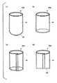
図1に示すように、複合プリフォーム70は、プリフォーム10aと、プリフォーム10aの外側を取り囲むように設けられたプラスチック製部材40aとを備える。Process for Preparing the
プリフォーム10aは、図1に示すように、口部11aと、口部11aに連結された胴部20aと、胴部20aに連結された底部30aとを備えている。このうち口部11aは、後述する容器本体10の口部11に対応するものであり、口部11と略同一の形状を有している(図5参照)。また、胴部20aは、容器本体10の首部13、肩部12および胴部20に対応するものであり、略円筒形状を有している。底部30aは、容器本体10の底部30に対応するものであり、略半球形状を有している。 As shown in FIG. 1, the
プリフォーム10a
プリフォーム10aは、熱可塑性樹脂、特にPE(ポリエチレン)、PP(ポリプロピレン)、PET(ポリエチレンテレフタレート)、PEN(ポリエチレンナフタレート)、PC(ポリカーボネート)やアイオノマー樹脂等の樹脂材料を含むことができる。これらの中でも、熱可塑性樹脂が好ましく、具体的には、PE(ポリエチレン)、PP(ポリプロピレン)、PET(ポリエチレンテレフタレート)、PEN(ポリエチレンナフタレート)、PC(ポリカーボネート)やアイオノマー樹脂が好ましい。また、上述した各種樹脂をブレンドして用いても良い。Preform 10a
The
また、プリフォーム10aは、赤色、青色、黄色、緑色、茶色、黒色、白色等の着色剤を含んでいても良いが、リサイクルのしやすさを考慮した場合、これら着色剤を含まず、無色透明であることが好ましい。 Further, the preform 10a may contain colorants such as red, blue, yellow, green, brown, black, and white, but when consideration is given to ease of recycling, the
一実施形態において、プリフォーム10aは、上記樹脂材料を従来公知の装置を使用して射出成形することにより製造することができる。
また、射出成形により2層以上の多層プリフォーム10aを作製することにより、容器本体10を2層以上の多層成形ボトルとすることができる。
例えば、中間層をMXD6、MXD6+脂肪酸塩、PGA(ポリグリコール酸)、EVOH(エチレンビニルアルコール共重合体)又はPEN(ポリエチレンナフタレート)等のガスバリア性及び遮光性を有する樹脂(中間層)を含んでなる層として、3層以上からなるプリフォーム10aを成形後、ブロー成形することによりガスバリア性及び遮光性などを有する多層成形ボトルを得ることができる。なお、中間層としては、上述した各種樹脂をブレンドした樹脂などを用いても良い。In one embodiment, the preform 10a can be produced by injection molding the resin material using a conventionally known device.
Further, by producing the multi-layer preform 10a having two or more layers by injection molding, the
For example, the intermediate layer contains a resin (intermediate layer) having gas barrier properties and light-shielding properties such as MXD6, MXD6 + fatty acid salt, PGA (polyglycolic acid), EVOH (ethylene vinyl alcohol copolymer) or PEN (polyethylene naphthalate). A multi-layer molded bottle having gas barrier properties, light-shielding properties, and the like can be obtained by molding a
また、熱可塑性樹脂の溶融物に不活性ガス(窒素ガス、アルゴンガス)を混ぜることで、0.5〜100μmの発泡セル径を持つ発泡プリフォームを成形し、この発泡プリフォームをブロー成形することによって、容器本体10を作製しても良い。このような容器本体10は、発泡セルを内蔵しているため、容器本体10全体の遮光性を高めることができる。 Further, by mixing an inert gas (nitrogen gas, argon gas) with the melt of the thermoplastic resin, a foam preform having a foam cell diameter of 0.5 to 100 μm is formed, and this foam preform is blow-molded. By doing so, the
プラスチック製部材40a
図1に示すように、プラスチック製部材40aは、プリフォーム10aの外面に接着されることなく取付けられており、プリフォーム10aに対して移動又は回転しないほどに密着されているか、又は自重で落下しない程度に密着されている。プラスチック製部材40aは、プリフォーム10aの外側を取り囲むようにその周方向全域にわたって設けられており、円形状の水平断面を有している。
図2(a)に示すように、プラスチック製部材40aは、有底円筒形状からなり、円筒状の胴部41と、胴部41に連結された底部42とを有していても良い。この場合、プラスチック製部材40aの底部42がプリフォーム10aの底部30aを覆うので、複合容器10Aの胴部20に加え、底部30に対しても様々な機能や特性を付与することができる。
また、図2(b)に示すように、プラスチック製部材40aは、全体として無底円筒形状からなり、円筒状の胴部41を有していても良い。
また、図2(c)および図2(d)に示すように、プラスチック製部材40aは、フィルムを筒状に形成してその端部を貼り合わせることにより作製されても良い。この場合、図2(c)に示すように、プラスチック製部材40aは、胴部41を有する無底円筒形状に構成されていても良く、図2(d)に示すように、底部42を貼り合わせることにより有底円筒形状に構成されていても良い。
As shown in FIG. 1, the
As shown in FIG. 2A, the
Further, as shown in FIG. 2B, the
Further, as shown in FIGS. 2 (c) and 2 (d), the
プラスチック製部材40aは、プリフォーム10aの口部11a以外の全域又は一部領域に設けられていても良い。例えば、プラスチック製部材40aは、プリフォーム10aの口部11aを除く、胴部20aおよび底部30aの全体を覆うように設けられていても良い。さらに、プラスチック製部材40aは1つに限らず、複数設けても良い。例えば、2つのプラスチック製部材40aをプリフォーム10aの胴部20aの外側2箇所にそれぞれ設けても良い。 The
プラスチック製部材40aは、例えば、PE、PP、PET、PEN、ポリ−4−メチルペンテン−1、ポリスチレン、AS樹脂、ABS樹旨、ポリ塩化ビニル、ポリ塩化ビニリデン、ポリ酢酸ビニル、ポリビニルアルコール、ポリビニルアセタール、ポリビニルブチラール、フタル酸ジアリル樹脂、フッ素系樹脂、ポリメタクリル酸メチル、ポリアクリル酸、ポリアクリル酸メチル、ポリアクリロニトリル、ポリアクリルアミド、ポリブタジエン、ポリブテン−1、ポリイソプレン、ポリクロロプレン、エチレンプロピレンゴム、ブチルゴム、ニトリルゴム、アクリルゴム、シリコーンゴム、フッ素ゴム、ナイロン6、ナイロン6,6、MXD6、芳香族ポリアミド、ポリカーボネート、ポリテレフタル酸エチレン、ポリテレフタル酸ブチレン、ポリナフタレン酸エチレン、Uポリマー、液晶ポリマー、変性ポリフェニレンエーテル、ポリエーテルケトン、ポリエーテルエーテルケトン、不飽和ポリエステル、アルキド樹脂、ポリイミド、ポリスルホン、ポリフェニレンスルフィド、ポリエーテルスルホン、シリコーン樹脂、ポリウレタン、フェノール樹脂、尿素樹脂、ポリエチレンオキシド、ポリプロピレンオキシド、ポリアセタール、エポキシ樹脂、アイオノマー樹脂等の樹脂材料を含むことができる。
これらの中でも、PE、PP、PET、PEN等の熱可塑性非弾性樹脂が特に好ましい。
また、プラスチック製部材40aは、上記した樹脂材料を構成する2以上のモノマー単位が重合した共重合体を含んでいても良い。さらに、上記した樹脂を2種以上を含んでいてもよい。The
Among these, thermoplastic inelastic resins such as PE, PP, PET and PEN are particularly preferable.
Further, the
また、プラスチック製部材40aは、酸素バリア性又は水蒸気バリア性等のガスバリア性を有する材料を含んでいても良い。
この場合、プリフォーム10aとして多層プリフォームやブレンド材料を含むプリフォーム等を用いることなく、複合容器10Aのガスバリア性を高め、容器内への酸素の侵入を防ぎ、内容液が劣化することを防止し、また、容器内から外部への水蒸気の蒸散を防ぎ、内容量が減少することを防止することができる。
例えば、後述する容器本体10のうち、肩部12、首部13および胴部20の全域および底部30の一部にプラスチック製部材40を設け、この部分のガスバリア性を高めても良い。
このような材料としては、PE、PP、MXD−6、PGA、EVOH、PENまたはこれらの材料に脂肪酸塩等の酸素吸収材を混ぜることも考えられる。
なお、プラスチック製部材40aが多層からなる場合は、ガスバリア性を有する材料からなる層を備えていてもよい。Further, the
In this case, without using a multi-layer preform or a preform containing a blended material as the
For example, in the
As such a material, PE, PP, MXD-6, PGA, EVOH, PEN, or an oxygen absorber such as a fatty acid salt may be mixed with these materials.
When the
また、プラスチック製部材40aは、紫外線等の光線バリア性を有する材料を含んでいても良い。
この場合、プリフォーム10aとして多層プリフォームやブレンド材料を含むプリフォーム等を用いることなく、複合容器10Aの光線バリア性を高め、紫外線等により内容液が劣化することを防止することができる。
例えば、容器本体10のうち、肩部12、首部13、胴部20の全域および底部の一部にプラスチック製部材40aを設け、この部分の紫外線バリア性を高めても良い。
このような材料としては、上記した樹脂を2種類以上含んでなる樹脂材料、またはPETやPE、PPに遮光性樹脂を添加した材料が考えられる。また、熱可塑性樹脂の溶融物に不活性ガス(窒素ガス、アルゴンガス)を混ぜることにより作製された、0.5〜100μmの発泡セル径を持つ発泡部材を使用しても良い。
なお、プラスチック製部材40aが多層からなる場合は、光線バリア性を有する材料からなる層を備えていてもよい。Further, the
In this case, it is possible to enhance the light barrier property of the
For example, in the container
As such a material, a resin material containing two or more kinds of the above-mentioned resins, or a material obtained by adding a light-shielding resin to PET, PE, or PP can be considered. Further, a foaming member having a foam cell diameter of 0.5 to 100 μm, which is produced by mixing an inert gas (nitrogen gas, argon gas) with the melt of the thermoplastic resin, may be used.
When the
また、プラスチック製部材40aは、プリフォーム10aを構成するプラスチック材料よりも保温性又は保冷性の高い材料(熱伝導性の低い材料)を含んでいても良い。
この場合、容器本体10そのものの厚みを厚くすることなく、内容液の温度が複合容器10Aの表面まで伝達しにくくすることが可能となる。これにより、複合容器10Aの保温性又は保冷性が高められる。
例えば、容器本体10のうち胴部20の全部又は一部にプラスチック製部材40を設け、胴部20の保温性又は保冷性を高めても良い。また、使用者が複合容器10Aを把持した際、熱すぎたり冷たすぎたりすることにより複合容器10Aを持ちにくくなることが防止される。このような材料としては、発泡化したポリウレタン、ポリスチレン、PE、PP、フェノール樹脂、ポリ塩化ビニル、ユリア樹脂、シリコーン、ポリイミド、メラミン樹脂などが考えられる。
なお、プラスチック製部材40aが多層からなる場合は、保温性又は保冷性の高い材料(熱伝導性の低い材料)からなる層を備えていてもよい。
また、これら樹脂を含んでなる樹脂材料に、中空粒子を混合することが好ましい。中空粒子の平均粒子径は、1〜200μmであることが好ましく、5〜80μmであることがより好ましい。また、中空粒子としては、樹脂などから構成される有機系中空粒子であってもよく、ガラスなどから構成される無機系中空粒子であってもよいが、分散性が優れるという理由から、有機系中空粒子が好ましい。有機系中空粒子を構成する樹脂としては、例えば、架橋スチレン−アクリル樹脂などのスチレン系樹脂、アクリロニトリル−アクリル樹脂などの(メタ)アクリル系樹脂、フェノール系樹脂、フッ素系樹脂、ポリアミド系樹脂、ポリイミド系樹脂、ポリカーボネート系樹脂、ポリエーテル系樹脂などを挙げることができる。また、ローペイクHP−1055、ローペイクHP−91、ローペイクOP−84J、ローペイクウルトラ、ローペイクSE、ローペイクST(ロームアンドハース(株)製)、ニポールMH−5055(日本ゼオン(株)製)、SX8782、SX866(JSR(株)製)などの市販される中空粒子を用いることも出来る。
中空粒子の含有量としては、プラスチック製部材40aが単層からなる場合、プラスチック製部材40aに含有される樹脂材料100質量部に対して、0.01〜50質量部であることが好ましく、1〜20質量部であることがより好ましい。また、プラスチック製部材40aが多層からなる場合、中空粒子が含まれるプラスチック製部材40aの層に含有される樹脂材料100質量部に対して、0.01〜50質量部であることが好ましく、1〜20質量部であることがより好ましい。Further, the
In this case, it is possible to make it difficult for the temperature of the content liquid to be transmitted to the surface of the
For example, the
When the
Further, it is preferable to mix hollow particles with the resin material containing these resins. The average particle size of the hollow particles is preferably 1 to 200 μm, more preferably 5 to 80 μm. Further, the hollow particles may be organic hollow particles composed of a resin or the like, or may be inorganic hollow particles composed of glass or the like, but are organic because of their excellent dispersibility. Hollow particles are preferred. Examples of the resin constituting the organic hollow particles include a styrene resin such as a crosslinked styrene-acrylic resin, a (meth) acrylic resin such as acrylonitrile-acrylic resin, a phenol resin, a fluorine resin, a polyamide resin, and a polyimide. Examples thereof include based resins, polycarbonate resins, and polyether resins. In addition, Low Pay HP-1055, Low Pay HP-91, Low Pay OP-84J, Low Pay Ultra, Low Pay SE, Low Pay ST (manufactured by Roam and Hearth Co., Ltd.), Nipole MH-5055 (manufactured by Nippon Zeon Co., Ltd.), SX8782 , SX866 (manufactured by JSR Corporation) and other commercially available hollow particles can also be used.
When the
また、プラスチック製部材40aは、プリフォーム10aを構成するプラスチック材料よりも滑りにくい材料を含んでいても良い。
この場合、容器本体10の材料を変更することなく、使用者が複合容器10Aを把持しやすくすることができる。例えば、容器本体10のうち胴部20の全部又は一部にプラスチック製部材40を設け、胴部20を持ちやすくしても良い。
なお、プラスチック製部材40aが多層からなる場合は、プリフォーム10aを構成するプラスチック材料よりも滑りにくい材料からなる層を備えていてもよい。この場合、該層は、プラスチック製部材40aの最外の層であることが好ましい。Further, the
In this case, the user can easily grip the
When the
さらに、プラスチック製部材40aには、デザイン又は印字が施されていても良い。この場合、ブロー成形後に容器本体10に対して別途ラベル等を付与することなく、複合容器10Aに画像や文字を表示することが可能となる。
例えば、容器本体10のうち胴部20の全部又は一部にプラスチック製部材40を設け、胴部20に画像や文字を表示しても良い。
印刷は、例えばインクジェット法、グラビア印刷法、オフセット印刷法、フレキソ印刷法等の印刷法により行うことができる。例えば、インクジェット法を用いる場合、プラスチック製部材40a(40)にUV硬化型インクを塗布し、これにUV照射を行い、硬化することにより印刷層を形成させることができる。この印刷は、プリフォーム10aに嵌め込む前のプラスチック製部材40aに対して施されても良く、プリフォーム10aの外側にプラスチック製部材40aを設けた状態で施されても良い。さらに、ブロー成形後の複合容器10Aのプラスチック製部材40に印刷が施されても良い。Further, the
For example, a
Printing can be performed by, for example, a printing method such as an inkjet method, a gravure printing method, an offset printing method, or a flexographic printing method. For example, when the inkjet method is used, a UV curable ink is applied to the
また、プラスチック製部材40aは、単層からなるものであっても、多層からなるものであってもよい。
プラスチック製部材40aが多層からなるものである場合、例えば、最内面と最外面との層構成が同じであっても、異なっていてもよい。
具体的な層構成としては、最内面から、低密度PE/接着層/EVOH/接着層/低密度PEのもの、PP/接着層/EVOH/接着層/PPのものなどを挙げることができる。
この場合の接着層を構成する接着剤としては、例えば、ポリ酢酸ビニル系接着剤、ポリアクリル酸エステル系接着剤、シアノアクリレート系接着剤、エチレン共重合体接着剤、セルロース系接着剤、ポリエステル系接着剤、ポリアミド系接着剤、ポリイミド系接着剤、アミノ樹脂系接着剤、フェノール樹脂系接着剤、エポキシ系接着剤、ポリウレタン系接着剤、ゴム系接着剤、シリコーン系接着剤などが挙げられる。Further, the
When the
Specific layer configurations include low-density PE / adhesive layer / EVOH / adhesive layer / low-density PE, PP / adhesive layer / EVOH / adhesive layer / PP, etc. from the innermost surface.
Examples of the adhesive constituting the adhesive layer in this case include a polyvinyl acetate adhesive, a polyacrylic acid ester adhesive, a cyanoacrylate adhesive, an ethylene copolymer adhesive, a cellulose adhesive, and a polyester adhesive. Examples thereof include adhesives, polyamide-based adhesives, polyimide-based adhesives, amino-resin-based adhesives, phenol-resin-based adhesives, epoxy-based adhesives, polyurethane-based adhesives, rubber-based adhesives, and silicone-based adhesives.
次に、プラスチック製部材40aの製造方法について説明する。 Next, a method of manufacturing the
一実施形態において、プラスチック製部材40aは、上記した樹脂材料などを含んでなる樹脂シートを成形することにより製造することができる。
成形方法としては、例えば、深絞り成形、または樹脂シートをチューブ状に成形し、その端部を融着、または接着する方法などが挙げられる。
また、多層からなるプラスチック製部材40aは、2以上の樹脂シートを、上記した接着剤を介して積層させた積層樹脂シートを成形することにより得ることができる。
上記樹脂シートは、市販品を用いてもよいし、従来公知の方法により製造することができる。本発明においては、押出成形により製造することが好ましく、押出成形が、Tダイ法またはインフレーション法により行われることが好ましい。In one embodiment, the
Examples of the molding method include deep drawing molding, or a method of molding a resin sheet into a tube shape and fusing or adhering its ends.
Further, the
The resin sheet may be a commercially available product, or may be produced by a conventionally known method. In the present invention, it is preferably produced by extrusion molding, and the extrusion molding is preferably carried out by a T-die method or an inflation method.
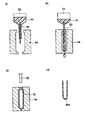
一実施形態において、プラスチック製部材40aは、図3(a)に示すように、
(1)まず樹脂材料51を加熱溶融し、ダイ52からチューブ状に押し出し、チューブ状パリソン53を形成させ、
(2)次いで、図3(b)に示すように、例えば2分割の金型54によりチューブ状パリソン53を挟み込み、
(3)次いで、図3(c)に示すように、吹き込みノズル55よりチューブ状パリソン53内に空気を吹き込み、チューブ状パリソン53を金型54に合わせて成形し、冷却、型開き、取り出しを順次行うことにより、図3(d)に示すような有底円筒形状のプラスチック製部材40aを得ることができる(ダイレクトブロー成形)。
本方法によれば、金型の設計を変更することにより、得られるプラスチック製部材40aの設計を変更することができ、プリフォーム10aとの密着性の高いプラスチック製部材40aを作製することができる。In one embodiment, the
(1) First, the
(2) Next, as shown in FIG. 3 (b), the
(3) Next, as shown in FIG. 3C, air is blown into the
According to this method, the design of the obtained
一実施形態において、熱収縮性のプラスチック製部材40aは、以下のような方法により作製することができる。
まず、上記した樹脂材料等を、押出装置内で加熱溶融し、溶融した樹脂材料等をリングダイより連続的に押し出し、冷却することにより、未延伸の押出チューブ1に成形する(図4(a)参照)。なお、多層からなるプラスチック製部材40aは、2以上の樹脂材料を共押し出しすることにより、作製することができる。
次いで、この未延伸の押出チューブの一端を溶着または接着することによって、押出チューブの一端を閉鎖する。
さらに、この一端が閉鎖された押出チューブ1を、押出チューブ1の外径よりも大きい内径を有する金型2内に配置する(図4(b)参照)。
次いで、押出チューブ1の他端にブロー装置3を配置(装着)する(図4(c)参照)。このとき、ブロー装置3は、押出チューブ1と、これらの間からエアが漏れないよう密着させることが好ましい。
続いて、押出チューブ1、金型2およびブロー装置3を、この配置のまま加熱炉4に送り込み、加熱炉4の内部で70〜150℃に加熱する(図4(d)参照)。加熱炉4としては、その内部を均一な温度にするために、熱風循環式加熱炉を用いても良い。あるいは押出チューブ1、金型2およびブロー装置3を、加熱した液体中を通過させることにより、これらを加熱しても良い。
次に、押出チューブ1、金型2およびブロー装置3を、加熱炉4から取り出し、ブロー装置3から押出チューブ1内にエアを噴出することにより、押出チューブ1の内面を加圧延伸する。これにより、押出チューブ1は、膨張し、金型2の内面形状に沿って拡径される(図4(e)参照)。
その後、ブロー装置3からエアを噴出した状態のまま、押出チューブ1を冷水中で冷却し、押出チューブを金型2から取り出す(図4(f)参照)。これを所望の大きさにカットすることにより熱収縮性のプラスチック製部材40aを得ることができる(図4(g)参照)。In one embodiment, the heat-
First, the above-mentioned resin material or the like is heated and melted in an extruder, and the melted resin material or the like is continuously extruded from a ring die and cooled to form an unstretched extrusion tube 1 (FIG. 4 (a)). )reference). The
One end of the extruded tube is then closed by welding or adhering one end of the unstretched extruded tube.
Further, the extruded tube 1 having one end closed is arranged in a
Next, the blow device 3 is arranged (mounted) on the other end of the extrusion tube 1 (see FIG. 4C). At this time, it is preferable that the blow device 3 is brought into close contact with the extrusion tube 1 so that air does not leak between them.
Subsequently, the extrusion tube 1, the
Next, the extrusion tube 1, the
Then, the extrusion tube 1 is cooled in cold water while the air is ejected from the blow device 3, and the extrusion tube is taken out from the mold 2 (see FIG. 4 (f)). By cutting this into a desired size, a heat-
また、一実施形態において、プラスチック製部材40aは、射出成形法によっても得ることができる。具体的には、まず、上記した樹脂材料などを含む混合物を加熱溶融する。次いで、加熱溶融した混合物を金型内に射出する。これを冷却し、金型内から取り出すことによっても、プラスチック製部材40aを得ることができる。 Further, in one embodiment, the
一実施形態において、複合プリフォーム70は、プラスチック製部材40aへプリフォーム10aを嵌め込むことにより得ることができる。
また、一実施形態において、複合プリフォーム70プラスチック製部材40aへプリフォーム10aを嵌め込んだ後、加熱し、プラスチック製部材40aを熱収縮させることにより得ることができる。
このとき、加熱方法は特に限定されず、赤外線や、温風等を用いて適宜行うことができる。加熱温度は、60℃以上、250℃以下であることが好ましく、80℃以上、150℃以下であることがより好ましい。なお、加熱温度とは加熱時の熱収縮性プラスチック製部材40aの表面温度のことであり、赤外線や、温風等の照射温度のことではない。In one embodiment, the
Further, in one embodiment, it can be obtained by fitting the
At this time, the heating method is not particularly limited, and it can be appropriately performed by using infrared rays, warm air, or the like. The heating temperature is preferably 60 ° C. or higher and 250 ° C. or lower, and more preferably 80 ° C. or higher and 150 ° C. or lower. The heating temperature is the surface temperature of the heat-
ブロー成形工程
複合プリフォーム70に対し、2軸延伸ブロー成形を施し、複合プリフォーム70のプリフォーム10aおよびプラスチック製部材40aを一体として膨張させることにより、図5および図6に示す複合容器10Aを得ることができる。Blow molding process The
以下、図7(a)〜(d)に基づいて、本発明の複合容器10Aの製造方法についてより詳しく説明する。 Hereinafter, the method for producing the
まず、複合プリフォーム70は、加熱装置51によって加熱される(図7(a)参照)。このとき、複合プリフォーム70は、口部11aを下に向けた状態で回転しながら、加熱装置51によって周方向に均等に加熱される。この加熱工程におけるプリフォーム10aおよびプラスチック製部材40aの加熱温度は、例えば90℃乃至130℃としても良い。
また、この加熱は、赤外線や、温風等を用いて適宜行うことができる。First, the
Further, this heating can be appropriately performed using infrared rays, warm air, or the like.
続いて、加熱装置51によって加熱された複合プリフォーム70は、ブロー成形金型50に送られる(図7(b)参照)。 Subsequently, the
複合容器10Aは、このブロー成形金型50を用いて成形される。この場合、ブロー成形金型50は、互いに分割された一対の胴部金型50a、50bと、底部金型50cとからなる(図7(b)参照)。図7(b)において、一対の胴部金型50a、50b間は互いに開いており、底部金型50cは上方に上がっている。この状態で一対の胴部金型50a、50b間に、複合プリフォーム70が挿入される。 The
次に、図7(c)に示すように、底部金型50cが下がったのちに一対の胴部金型50a、50bが閉鎖され、一対の胴部金型50a、50bおよび底部金型50cにより密閉されたブロー成形金型50が構成される。次にプリフォーム10a内に空気が圧入され、複合プリフォーム70に対して2軸延伸ブロー成形が施される。 Next, as shown in FIG. 7C, after the
このことにより、ブロー成形金型50内でプリフォーム10aから容器本体10が得られる。この間、胴部金型50a、50bは30℃乃至80℃まで加熱され、底部金型50cは5℃乃至25℃まで冷却される。この際、ブロー成形金型50内では、複合プリフォーム70のプリフォーム10aおよびプラスチック製部材40aが一体として膨張される。これにより、プリフォーム10aおよびプラスチック製部材40aは、一体となってブロー成形金型50の内面に対応する形状に賦形される。 As a result, the
このようにして、容器本体10と、容器本体10の外面に設けられたプラスチック製部材40とを備えた複合容器10Aが得られる。 In this way, the
次に、図7(d)に示すように、一対の胴部金型50a、50bおよび底部金型50cが互いに離れ、ブロー成形金型50内から複合容器10Aが取出される。 Next, as shown in FIG. 7D, the pair of
複合容器10A
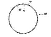
図5に示すように、複合プリフォーム70をブロー成形することにより得られる複合容器10Aは、内側に位置するプラスチック材料製の容器本体10と、容器本体10の外側に密着して設けられたプラスチック製部材40とを備えている。
As shown in FIG. 5, the
容器本体10
容器本体10は、口部11と、口部11下方に設けられた首部13と、首部13下方に設けられた肩部12と、肩部12の下方に設けられた胴部20と、胴部20下方に設けられた底部30とを備えている。なお、本明細書中、「上」および「下」とは、それぞれ複合容器10Aを正立させた状態(図5)における上方および下方のことをいう。
The
口部11は、図示しないキャップに螺着されるねじ部14と、ねじ部14下方に設けられたフランジ部17とを有している。なお、口部11の形状は、従来公知の形状であっても良い。 The
首部13は、フランジ部17と肩部12との間に位置しており、略均一な径をもつ略円筒形状を有している。また、肩部12は、首部13と胴部20との間に位置しており、首部13側から胴部20側に向けて徐々に径が拡大する形状を有している。 The
さらに、胴部20は、全体として略均一な径をもつ円筒形状を有している。しかしながら、これに限られるものではなく、胴部20が四角形筒形状や八角形筒形状等の多角形筒形状を有していても良い。あるいは、胴部20が上方から下方に向けて均一でない水平断面をもつ筒形状を有していても良い。また、本実施の形態において、胴部20は、凹凸が形成されておらず、略平坦な表面を有しているが、これに限られるものではない。例えば、胴部20にパネル又は溝等の凹凸が形成されていても良い。 Further, the
底部30は、中央に位置する凹部31と、この凹部31周囲に設けられた接地部32とを有している。なお、底部30の形状についても特に限定されるものではなく、従来公知の底部形状(例えばペタロイド底形状や丸底形状等)を有していても良い。 The
また、胴部20における容器本体10の厚みは、これに限定されるものではないが、例えば50μm〜250μm程度に薄くすることができる。さらに、容器本体10の重量についても、これに限定されるものではないが、例えば、容器本体10の内容量が500mLである場合は、10g〜20gとすることができる。このように容器本体10の肉厚を薄くすることにより、容器本体10の軽量化を図ることができる。 Further, the thickness of the
一実施形態において、容器本体10は、樹脂材料を射出成形して製作したプリフォーム10aを二軸延伸ブロー成形することにより作製することができる。 In one embodiment, the
容器本体10の内面に、容器のバリア性を高めるために、例えばダイヤモンド状炭素膜や酸化珪素薄膜等の蒸着膜を形成しても良い。 A thin-film film such as a diamond-like carbon film or a silicon oxide thin film may be formed on the inner surface of the
容器本体10は、例えば満注容量が100mL〜2000mLのボトルからなっていても良い。あるいは、容器本体10は、満注容量が例えば10L〜60Lの大型のボトルであっても良い。 The
プラスチック製部材40
プラスチック製部材40は、容器本体10の外面に薄く延ばされた状態で密着されており、容器本体10に対して容易に移動又は回転しない状態で取付けられている。また、図3に示すように、プラスチック製部材40は、容器本体10を取り囲むようにその周方向全域にわたって設けられており、略円形状の水平断面を有している。
The
プラスチック製部材40は、プラスチック製部材40aを、後述するようにプリフォーム10aの外側を取り囲むように設け、プリフォーム10aの外側に密着させた後、プリフォーム10aとともに2軸延伸ブロー成形することにより得ることができる。 The
図5に示すように、プラスチック製部材40は、容器本体10のうち、口部11および首部13を除く、肩部12、胴部20および底部30を覆うように設けることができる。このような構成とすることにより、容器本体10の肩部12、胴部20および底部30に対して所望の機能や特性を付与することができる。 As shown in FIG. 5, the
なお、プラスチック製部材40は、容器本体10のうち口部11以外の全域又は一部領域に設けられていても良い。例えば、プラスチック製部材40は、容器本体10のうち、口部11を除く、首部13、肩部12、胴部20および底部30の全体を覆うように設けられていても良い。さらに、プラスチック製部材40は1つに限らず、複数設けても良い。例えば、2つのプラスチック製部材40を肩部12の外面および底部30の外面にそれぞれ設けても良い。 The
また、プラスチック製部材40の厚みは、これに限定されるものではないが、容器本体10に取り付けられた状態で例えば5μm〜50μm程度とすることができる。 The thickness of the
また、プラスチック製部材40は、容器本体10に対して溶着ないし接着されていないため、容器本体10から分離(剥離)して除去することができる。
プラスチック製部材40の容器本体10からの分離(剥離)の方法としては、例えば刃物等を用いてプラスチック製部材40を切除したり、プラスチック製部材40に予め切断線を設け、この切断線に沿ってプラスチック製部材40を剥離したりすることができる。上記のような方法により、プラスチック製部材40を容器本体10から分離除去することができるので、従来と同様に無色透明な容器本体10をリサイクルすることができる。Further, since the
As a method of separating (peeling) the
充填工程
複合容器10Aに充填する内容物は、特に限定されるものではないが、本発明の方法によれば、加熱工程を経ることなく、内容物および複合容器10Aを殺菌することができるため、熱により変性してしまうもの(例えば、乳製品)や、生酒、野菜ジュース等の加熱処理に適さない飲料を内容物として充填することができる。
複合容器10Aへの内容物の充填は、ヘッドスペース(空寸量)ができるように行われることが好ましく、このヘッドスペースは、1mL以上、20mL以下であることが好ましく、5mL以上、10mL以下であることが好ましい。Filling step The contents to be filled in the
The content in the
高圧処理工程
本発明の方法は、内容物を充填した複合容器10Aを高圧処理する工程を含み、内容物が、熱により変性等を起こしてしまうものであったとしても、殺菌処理を施すことが可能となる。また、内容物によっては、食味の向上や酵素活性の向上等の効果も認められる。
内容物を充填し、キャップを螺着した複合容器10Aの高圧処理は、従来公知の高圧処理装置を用いて行うことができ、例えば、水等の液状圧力媒体が充填されてなる加圧室を有する装置を使用することができる。
市販される高圧処理装置としては、例えば、株式会社神戸製鋼所社製の食品用高圧処理装置が挙げられる。
高圧処理における圧力は、10MPa以上、2000MPa以下であることが好ましく、100MPa以上、1000MPa以下であることがより好ましい。
また、高圧処理の時間は、内容物、使用する装置、圧力の高さ等に応じ適宜変更されることが好ましいが、例えば、10秒以上、30分以下とすることができる。
また、高圧処理は、内容物の温度が80℃以下となるように行われることが好ましく、50℃以下の温度となるように行われることがより好ましい。
また、高圧後の複合容器10A内の圧力は、100kPa以上、150kPa以下となるように行われることが好ましく、100kPa以上、125kPa以下となるように行われることがより好ましい。容器本体10Aの形状は、この圧力に耐えることができるものであれば特に限定されるものではない。High-pressure treatment step The method of the present invention includes a step of high-pressure treatment of the
The high-pressure treatment of the
Examples of commercially available high-pressure processing equipment include food-grade high-pressure processing equipment manufactured by Kobe Steel, Ltd.
The pressure in the high pressure treatment is preferably 10 MPa or more and 2000 MPa or less, and more preferably 100 MPa or more and 1000 MPa or less.
The time of high-pressure treatment is preferably changed as appropriate according to the contents, the apparatus used, the height of pressure, and the like, but can be, for example, 10 seconds or more and 30 minutes or less.
Further, the high pressure treatment is preferably performed so that the temperature of the contents is 80 ° C. or lower, and more preferably 50 ° C. or lower.
Further, the pressure in the
以下、実施例により、本発明をさらに詳細に説明するが、本発明がこれら実施例に限定されるものではない。 Hereinafter, the present invention will be described in more detail with reference to Examples, but the present invention is not limited to these Examples.
(プリフォーム10aを準備する工程)
射出成形機を使用して、図1に示すPET製のプリフォーム10aを作製した。このプリフォーム10aの重量は、23.8gであった。(Step of preparing
Using an injection molding machine, a
(熱収縮性プラスチック製部材40aを準備する工程)
ポリオレフィン樹脂を溶融し、リング状のダイから押出した。次いで、押出されたチューブ内面を加圧、またはチューブ外面を内面より陰圧とし拡径を行い、熱収縮性プラスチック製部材40a作製した。(Step of preparing the heat-
The polyolefin resin was melted and extruded from a ring-shaped die. Next, the inner surface of the extruded tube was pressurized, or the outer surface of the tube was negatively pressured from the inner surface to increase the diameter, and a heat-
(嵌め込み工程)
次いで、手作業により、プリフォーム10aを、熱収縮性プラスチック製部材40aの余白部80aとは反対の端から嵌め込みを行った。(Matching process)
Then, the
(熱収縮工程)
嵌め込み後、赤外線ヒーターを用いて、プリフォーム10aおよび熱収縮性プラスチック製部材40aを100℃まで加熱し、熱収縮性プラスチック製部材40aを熱収縮させた。(Heat shrinkage process)
After fitting, the
(複合容器の製造)
上記のようにして得られた複合プリフォーム70を赤外線ヒーターを用いて、100℃まで加熱し、図7bに表されるブロー成形金型に搬送した。このブロー成形金型内において、複合プリフォーム70をブロー成形し、満注容量が500mLの複合容器10Aを得た。(Manufacturing of composite container)
The
(内容物の充填工程)
上記のようにして得られた複合容器10Aへ、内容物(水)を、15mLのヘッドスペースができるように充填し、キャップを螺着した。(Content filling process)
The
(高圧処理工程)
内容物を充填した複合容器10Aを、株式会社神戸製鋼所社製の食品用高圧処理装置内へ入れ、500MPa、1分間高圧処理を施した。
高圧処理後の複合容器10A内の圧力を針付き圧力計を用いて測定したところ、110kPaであった。
また、高圧処理時の内容物の温度は、10℃であった。(High pressure processing process)
The
When the pressure in the
The temperature of the contents during the high pressure treatment was 10 ° C.
Claims (2)
Translated fromJapanese前記複合プリフォームをブロー成形し、複合容器を得る工程と、
前記複合容器に内容物を充填する工程と、
前記内容物を充填した複合容器を高圧処理する工程と、を含み、
前記高圧処理が、50℃以下の内容物温度において行われ、
前記高圧処理における圧力が、10MPa以上、2000MPa以下であり、
前記高圧処理後の前記複合容器内の圧力が、100kPa以上、150kPa以下である、飲料製品の製造方法。A step of preparing a preform and a composite preform including a plastic member provided so as to surround the outside of the preform, and
The process of blow-molding the composite preform to obtain a composite container and
The step of filling the composite container with the contents and
Including a step of high-pressure processing a composite container filled with the contents.
The high pressure treatment is performed at a content temperature of 50 ° C. or lower.
The pressure in the high pressure treatment is 10 MPa or more and 2000 MPa or less.
The pressure in the composite container after high pressure treatment, or 100 kPa, Ruder below 150 kPa, a manufacturing method of a beverage product.
Priority Applications (1)
| Application Number | Priority Date | Filing Date | Title |
|---|---|---|---|
| JP2016125905AJP6880473B2 (en) | 2016-06-24 | 2016-06-24 | Beverage product manufacturing method |
Applications Claiming Priority (1)
| Application Number | Priority Date | Filing Date | Title |
|---|---|---|---|
| JP2016125905AJP6880473B2 (en) | 2016-06-24 | 2016-06-24 | Beverage product manufacturing method |
Publications (2)
| Publication Number | Publication Date |
|---|---|
| JP2017226473A JP2017226473A (en) | 2017-12-28 |
| JP6880473B2true JP6880473B2 (en) | 2021-06-02 |
Family
ID=60890830
Family Applications (1)
| Application Number | Title | Priority Date | Filing Date |
|---|---|---|---|
| JP2016125905AActiveJP6880473B2 (en) | 2016-06-24 | 2016-06-24 | Beverage product manufacturing method |
Country Status (1)
| Country | Link |
|---|---|
| JP (1) | JP6880473B2 (en) |
Family Cites Families (10)
| Publication number | Priority date | Publication date | Assignee | Title |
|---|---|---|---|---|
| JPH03219855A (en)* | 1990-01-23 | 1991-09-27 | Toppan Printing Co Ltd | High pressure treatment |
| JP2655963B2 (en)* | 1991-03-07 | 1997-09-24 | 株式会社神戸製鋼所 | High pressure processing method and processing equipment for food etc. |
| JPH05328950A (en)* | 1992-06-02 | 1993-12-14 | Kobe Steel Ltd | High-pressure bactericidal method at low temperature |
| HUT74962A (en)* | 1993-09-24 | 1997-03-28 | Unilever Nv | Shelf stable product |
| ES2304803T3 (en)* | 1999-04-29 | 2008-10-16 | Sidel S.P.A. | CONTINUOUS METHOD AND APPLIANCE FOR THE STERILIZATION OF BOTTLED BEVERAGES. |
| JP2006137463A (en)* | 2004-11-12 | 2006-06-01 | Toyo Seikan Kaisha Ltd | Manufacturing method and apparatus for plastic bottled beverage |
| JP5299891B2 (en)* | 2008-08-29 | 2013-09-25 | 大和製罐株式会社 | Method for producing chilled food in a container |
| WO2013147065A1 (en)* | 2012-03-30 | 2013-10-03 | 株式会社吉野工業所 | Method for manufacturing container containing content fluid, method for pressurizing interior of container, filled container, blow-molding method, and blow-molding device |
| JP2015147612A (en)* | 2014-02-07 | 2015-08-20 | 東洋製罐株式会社 | Method of producing packed acid beverage |
| JP6413571B2 (en)* | 2014-09-30 | 2018-10-31 | 大日本印刷株式会社 | Composite container manufacturing method, composite container filling method, and composite container filling apparatus |
- 2016
- 2016-06-24JPJP2016125905Apatent/JP6880473B2/enactiveActive
Also Published As
| Publication number | Publication date |
|---|---|
| JP2017226473A (en) | 2017-12-28 |
Similar Documents
| Publication | Publication Date | Title |
|---|---|---|
| JP2021151796A (en) | Composite preform, manufacturing method thereof, composite container, and manufacturing method thereof | |
| JP7446701B2 (en) | Composite container, manufacturing method thereof, and mold used in the manufacturing method of composite container | |
| JP6853945B2 (en) | Composite preforms, composite containers and plastic components | |
| JP6814402B2 (en) | Manufacturing method of composite preform, composite container and composite preform | |
| JP6686273B2 (en) | Blow molding method | |
| JP6880473B2 (en) | Beverage product manufacturing method | |
| JP6907717B2 (en) | Manufacturing method of composite preform and manufacturing method of composite container | |
| JP6935838B2 (en) | Manufacturing method of composite container | |
| JP7001988B2 (en) | Composite container | |
| JP2021080027A (en) | Composite container, manufacturing method of the same, composite preform, and plastic member | |
| JP6701780B2 (en) | Method for manufacturing composite preform and method for manufacturing composite container | |
| JP6681036B2 (en) | Composite container and method of manufacturing the same, plastic member and composite preform | |
| JP7068667B2 (en) | Manufacturing method of composite preform, composite container and composite preform | |
| JP7148899B2 (en) | Composite container manufacturing method | |
| JP6759810B2 (en) | Manufacturing method of composite container | |
| JP6895107B2 (en) | Composite preforms and composite containers | |
| JP2020152421A (en) | Composite container | |
| JP7130915B2 (en) | Composite container | |
| JP6722395B2 (en) | Manufacturing method of composite preform and manufacturing method of composite container | |
| JP6850443B2 (en) | Composite containers and their manufacturing methods, composite preforms, and plastic components | |
| JP6921479B2 (en) | Composite containers, composite preforms and plastic components | |
| JP7070742B2 (en) | Composite preforms, composite containers and plastic components | |
| JP7037772B2 (en) | Composite containers and their manufacturing methods, composite preforms, and plastic components | |
| JP7242398B2 (en) | Composite container manufacturing method and manufacturing device, composite preform manufacturing method and manufacturing device | |
| JP6951690B2 (en) | Blow molding methods, composite preforms, composite containers and plastic components |
Legal Events
| Date | Code | Title | Description |
|---|---|---|---|
| A621 | Written request for application examination | Free format text:JAPANESE INTERMEDIATE CODE: A621 Effective date:20190425 | |
| A977 | Report on retrieval | Free format text:JAPANESE INTERMEDIATE CODE: A971007 Effective date:20200207 | |
| A131 | Notification of reasons for refusal | Free format text:JAPANESE INTERMEDIATE CODE: A131 Effective date:20200214 | |
| A521 | Written amendment | Free format text:JAPANESE INTERMEDIATE CODE: A523 Effective date:20200407 | |
| A02 | Decision of refusal | Free format text:JAPANESE INTERMEDIATE CODE: A02 Effective date:20201002 | |
| A521 | Written amendment | Free format text:JAPANESE INTERMEDIATE CODE: A523 Effective date:20201211 | |
| C60 | Trial request (containing other claim documents, opposition documents) | Free format text:JAPANESE INTERMEDIATE CODE: C60 Effective date:20201211 | |
| A911 | Transfer of reconsideration by examiner before appeal (zenchi) | Free format text:JAPANESE INTERMEDIATE CODE: A911 Effective date:20201218 | |
| C21 | Notice of transfer of a case for reconsideration by examiners before appeal proceedings | Free format text:JAPANESE INTERMEDIATE CODE: C21 Effective date:20201222 | |
| TRDD | Decision of grant or rejection written | ||
| A01 | Written decision to grant a patent or to grant a registration (utility model) | Free format text:JAPANESE INTERMEDIATE CODE: A01 Effective date:20210402 | |
| A61 | First payment of annual fees (during grant procedure) | Free format text:JAPANESE INTERMEDIATE CODE: A61 Effective date:20210415 | |
| R150 | Certificate of patent or registration of utility model | Ref document number:6880473 Country of ref document:JP Free format text:JAPANESE INTERMEDIATE CODE: R150 |