JP6879957B2 - Reference station equipment - Google Patents
Reference station equipmentDownload PDFInfo
- Publication number
- JP6879957B2 JP6879957B2JP2018020903AJP2018020903AJP6879957B2JP 6879957 B2JP6879957 B2JP 6879957B2JP 2018020903 AJP2018020903 AJP 2018020903AJP 2018020903 AJP2018020903 AJP 2018020903AJP 6879957 B2JP6879957 B2JP 6879957B2
- Authority
- JP
- Japan
- Prior art keywords
- reference station
- positioning
- communication antenna
- antenna
- main body
- Prior art date
- Legal status (The legal status is an assumption and is not a legal conclusion. Google has not performed a legal analysis and makes no representation as to the accuracy of the status listed.)
- Active
Links
- 238000004891communicationMethods0.000claimsdescription93
- 238000000034methodMethods0.000description53
- 238000009434installationMethods0.000description14
- 230000036544postureEffects0.000description14
- 238000012937correctionMethods0.000description13
- 238000003780insertionMethods0.000description4
- 230000037431insertionEffects0.000description4
- 238000012545processingMethods0.000description4
- 238000010586diagramMethods0.000description3
- 230000005540biological transmissionEffects0.000description2
- 230000006866deteriorationEffects0.000description2
- 239000000428dustSubstances0.000description2
- 239000000945fillerSubstances0.000description2
- 238000004804windingMethods0.000description2
- 240000007594Oryza sativaSpecies0.000description1
- 235000007164Oryza sativaNutrition0.000description1
- 238000010276constructionMethods0.000description1
- 230000005484gravityEffects0.000description1
- 239000004973liquid crystal related substanceSubstances0.000description1
- 230000005389magnetismEffects0.000description1
- 238000005259measurementMethods0.000description1
- 235000009566riceNutrition0.000description1
- 230000000007visual effectEffects0.000description1
Images


Classifications
- G—PHYSICS
- G01—MEASURING; TESTING
- G01S—RADIO DIRECTION-FINDING; RADIO NAVIGATION; DETERMINING DISTANCE OR VELOCITY BY USE OF RADIO WAVES; LOCATING OR PRESENCE-DETECTING BY USE OF THE REFLECTION OR RERADIATION OF RADIO WAVES; ANALOGOUS ARRANGEMENTS USING OTHER WAVES
- G01S19/00—Satellite radio beacon positioning systems; Determining position, velocity or attitude using signals transmitted by such systems
- G01S19/01—Satellite radio beacon positioning systems transmitting time-stamped messages, e.g. GPS [Global Positioning System], GLONASS [Global Orbiting Navigation Satellite System] or GALILEO
- G01S19/03—Cooperating elements; Interaction or communication between different cooperating elements or between cooperating elements and receivers
- G01S19/07—Cooperating elements; Interaction or communication between different cooperating elements or between cooperating elements and receivers providing data for correcting measured positioning data, e.g. DGPS [differential GPS] or ionosphere corrections
- G—PHYSICS
- G01—MEASURING; TESTING
- G01S—RADIO DIRECTION-FINDING; RADIO NAVIGATION; DETERMINING DISTANCE OR VELOCITY BY USE OF RADIO WAVES; LOCATING OR PRESENCE-DETECTING BY USE OF THE REFLECTION OR RERADIATION OF RADIO WAVES; ANALOGOUS ARRANGEMENTS USING OTHER WAVES
- G01S19/00—Satellite radio beacon positioning systems; Determining position, velocity or attitude using signals transmitted by such systems
- G01S19/01—Satellite radio beacon positioning systems transmitting time-stamped messages, e.g. GPS [Global Positioning System], GLONASS [Global Orbiting Navigation Satellite System] or GALILEO
- G01S19/13—Receivers
- G01S19/35—Constructional details or hardware or software details of the signal processing chain
- H—ELECTRICITY
- H01—ELECTRIC ELEMENTS
- H01Q—ANTENNAS, i.e. RADIO AERIALS
- H01Q1/00—Details of, or arrangements associated with, antennas
- H01Q1/12—Supports; Mounting means
- H01Q1/1207—Supports; Mounting means for fastening a rigid aerial element
- G—PHYSICS
- G01—MEASURING; TESTING
- G01S—RADIO DIRECTION-FINDING; RADIO NAVIGATION; DETERMINING DISTANCE OR VELOCITY BY USE OF RADIO WAVES; LOCATING OR PRESENCE-DETECTING BY USE OF THE REFLECTION OR RERADIATION OF RADIO WAVES; ANALOGOUS ARRANGEMENTS USING OTHER WAVES
- G01S19/00—Satellite radio beacon positioning systems; Determining position, velocity or attitude using signals transmitted by such systems
- G01S19/01—Satellite radio beacon positioning systems transmitting time-stamped messages, e.g. GPS [Global Positioning System], GLONASS [Global Orbiting Navigation Satellite System] or GALILEO
- G01S19/03—Cooperating elements; Interaction or communication between different cooperating elements or between cooperating elements and receivers
- G01S19/04—Cooperating elements; Interaction or communication between different cooperating elements or between cooperating elements and receivers providing carrier phase data
- G—PHYSICS
- G01—MEASURING; TESTING
- G01S—RADIO DIRECTION-FINDING; RADIO NAVIGATION; DETERMINING DISTANCE OR VELOCITY BY USE OF RADIO WAVES; LOCATING OR PRESENCE-DETECTING BY USE OF THE REFLECTION OR RERADIATION OF RADIO WAVES; ANALOGOUS ARRANGEMENTS USING OTHER WAVES
- G01S19/00—Satellite radio beacon positioning systems; Determining position, velocity or attitude using signals transmitted by such systems
- G01S19/01—Satellite radio beacon positioning systems transmitting time-stamped messages, e.g. GPS [Global Positioning System], GLONASS [Global Orbiting Navigation Satellite System] or GALILEO
- G01S19/03—Cooperating elements; Interaction or communication between different cooperating elements or between cooperating elements and receivers
- G01S19/07—Cooperating elements; Interaction or communication between different cooperating elements or between cooperating elements and receivers providing data for correcting measured positioning data, e.g. DGPS [differential GPS] or ionosphere corrections
- G01S19/071—DGPS corrections
- G—PHYSICS
- G01—MEASURING; TESTING
- G01S—RADIO DIRECTION-FINDING; RADIO NAVIGATION; DETERMINING DISTANCE OR VELOCITY BY USE OF RADIO WAVES; LOCATING OR PRESENCE-DETECTING BY USE OF THE REFLECTION OR RERADIATION OF RADIO WAVES; ANALOGOUS ARRANGEMENTS USING OTHER WAVES
- G01S19/00—Satellite radio beacon positioning systems; Determining position, velocity or attitude using signals transmitted by such systems
- G01S19/38—Determining a navigation solution using signals transmitted by a satellite radio beacon positioning system
- G01S19/39—Determining a navigation solution using signals transmitted by a satellite radio beacon positioning system the satellite radio beacon positioning system transmitting time-stamped messages, e.g. GPS [Global Positioning System], GLONASS [Global Orbiting Navigation Satellite System] or GALILEO
- G01S19/40—Correcting position, velocity or attitude
- G01S19/41—Differential correction, e.g. DGPS [differential GPS]
- H—ELECTRICITY
- H01—ELECTRIC ELEMENTS
- H01Q—ANTENNAS, i.e. RADIO AERIALS
- H01Q1/00—Details of, or arrangements associated with, antennas
- H01Q1/12—Supports; Mounting means
- H—ELECTRICITY
- H01—ELECTRIC ELEMENTS
- H01Q—ANTENNAS, i.e. RADIO AERIALS
- H01Q1/00—Details of, or arrangements associated with, antennas
- H01Q1/12—Supports; Mounting means
- H01Q1/22—Supports; Mounting means by structural association with other equipment or articles
- H01Q1/2291—Supports; Mounting means by structural association with other equipment or articles used in bluetooth or WI-FI devices of Wireless Local Area Networks [WLAN]
- H—ELECTRICITY
- H01—ELECTRIC ELEMENTS
- H01Q—ANTENNAS, i.e. RADIO AERIALS
- H01Q1/00—Details of, or arrangements associated with, antennas
- H01Q1/12—Supports; Mounting means
- H01Q1/22—Supports; Mounting means by structural association with other equipment or articles
- H01Q1/24—Supports; Mounting means by structural association with other equipment or articles with receiving set
- H01Q1/241—Supports; Mounting means by structural association with other equipment or articles with receiving set used in mobile communications, e.g. GSM
- H—ELECTRICITY
- H01—ELECTRIC ELEMENTS
- H01Q—ANTENNAS, i.e. RADIO AERIALS
- H01Q21/00—Antenna arrays or systems
- H01Q21/28—Combinations of substantially independent non-interacting antenna units or systems
- H—ELECTRICITY
- H01—ELECTRIC ELEMENTS
- H01Q—ANTENNAS, i.e. RADIO AERIALS
- H01Q5/00—Arrangements for simultaneous operation of antennas on two or more different wavebands, e.g. dual-band or multi-band arrangements
- H01Q5/30—Arrangements for providing operation on different wavebands
- H01Q5/307—Individual or coupled radiating elements, each element being fed in an unspecified way
- H—ELECTRICITY
- H01—ELECTRIC ELEMENTS
- H01Q—ANTENNAS, i.e. RADIO AERIALS
- H01Q9/00—Electrically-short antennas having dimensions not more than twice the operating wavelength and consisting of conductive active radiating elements
- H01Q9/04—Resonant antennas
- H01Q9/30—Resonant antennas with feed to end of elongated active element, e.g. unipole
- H01Q9/32—Vertical arrangement of element
- H01Q9/34—Mast, tower, or like self-supporting or stay-supported antennas
Landscapes
- Engineering & Computer Science (AREA)
- Radar, Positioning & Navigation (AREA)
- Remote Sensing (AREA)
- Computer Networks & Wireless Communication (AREA)
- Physics & Mathematics (AREA)
- General Physics & Mathematics (AREA)
- Signal Processing (AREA)
- Position Fixing By Use Of Radio Waves (AREA)
- Support Of Aerials (AREA)
Description
Translated fromJapanese本発明は、移動局との間で無線通信を行う通信用アンテナと、測位衛星から測位信号を受信する測位用アンテナと、前記測位用アンテナ及び前記通信用アンテナの作動を制御する制御ユニットと、を備えた基準局装置に関する。 The present invention includes a communication antenna for wireless communication with a mobile station, a positioning antenna for receiving a positioning signal from a positioning satellite, a positioning antenna, and a control unit for controlling the operation of the communication antenna. With respect to a reference station device equipped with.
近年、作業地での作業車両による農作業等を効率よく行うために、当該作業車両を自動走行させるための自動走行システムが開発されている(例えば、特許文献1を参照。)。このような自動走行システムでは、測位衛星からの測位信号を受信する測位用アンテナを、作業地を走行する移動局としての作業車両と、当該作業地近傍に設置された基準局としての基準局装置との双方に設置し、これら移動局と基準局の双方の測位用アンテナにて受信した測位信号を用いて、移動局である作業車両の現在位置を精度良く測位する。
また、このような自動走行システムで利用される基準局装置は、作業車両の走行領域に併せて適切な位置に設置することが望ましいため、可搬型として構成することが求められている。In recent years, an automatic traveling system for automatically traveling the working vehicle has been developed in order to efficiently perform agricultural work or the like by the working vehicle in the work area (see, for example, Patent Document 1). In such an automatic traveling system, a positioning antenna for receiving a positioning signal from a positioning satellite is provided by a work vehicle as a mobile station traveling on a work site and a reference station device as a reference station installed near the work site. It is installed on both sides, and the current position of the work vehicle, which is a mobile station, is accurately positioned using the positioning signals received by the positioning antennas of both the mobile station and the reference station.
Further, since it is desirable that the reference station device used in such an automatic traveling system be installed at an appropriate position according to the traveling area of the work vehicle, it is required to be configured as a portable type.
尚、携帯端末用の通信ネットワークの分野においては、簡易に設置可能な可搬型基地局装置(アクセスポイント)が提供されている(例えば、特許文献2を参照。)。しかしながら、この特許文献2の可搬型の基地局装置は、端末装置との通信を目的とするものであって、作業車両の自動走行システムに利用される基準局装置のように、測位衛星との通信を行うものではない。 In the field of communication networks for mobile terminals, portable base station devices (access points) that can be easily installed are provided (see, for example, Patent Document 2). However, the portable base station device of
自動走行システムに利用される基準局装置では、移動局となる作業車両との通信状態を良好なものとするために、移動局との間で無線通信を行う通信用アンテナについては、高い位置に設置することが好ましい。一方、測位用アンテナについては、比較的重量があるため、高い位置に設置した場合には、不安定となって転倒し易くなる上に、測位のずれが生じ易くなる。 In the reference station equipment used in the autonomous driving system, the communication antenna that performs wireless communication with the mobile station is installed at a high position in order to improve the communication status with the work vehicle that is the mobile station. It is preferable to do so. On the other hand, since the positioning antenna is relatively heavy, when it is installed at a high position, it becomes unstable and easily falls, and the positioning is likely to be displaced.
この実情に鑑み、本発明の主たる課題は、可搬型に構成した場合でも安定姿勢を維持しつつ、高精度な測位が可能となる基準局装置を提供する点にある。 In view of this situation, a main object of the present invention is to provide a reference station apparatus capable of highly accurate positioning while maintaining a stable posture even when configured in a portable type.
本発明の第1特徴構成は、移動局との間で無線通信を行う通信用アンテナと、
測位衛星から測位信号を受信する測位用アンテナと、
前記測位用アンテナ及び前記通信用アンテナの作動を制御する制御ユニットと、を備えた基準局装置であって、
前記制御ユニット及び前記測位用アンテナが取り付けられて地表面に支持される基準局本体と、
前記通信用アンテナを前記基準局本体よりも上方に支持する通信用アンテナ支持部と、
前記基準局本体に対して前記通信用アンテナ支持部を着脱自在に取り付ける通信用アンテナ取付部と、を備えた点にある。The first characteristic configuration of the present invention includes a communication antenna for wireless communication with a mobile station and a communication antenna.
A positioning antenna that receives positioning signals from positioning satellites, and
A reference station device including the positioning antenna and a control unit that controls the operation of the communication antenna.
A reference station body to which the control unit and the positioning antenna are attached and supported on the ground surface,
A communication antenna support portion that supports the communication antenna above the reference station body, and a communication antenna support portion.
The point is that the communication antenna support portion is detachably attached to the reference station main body, and the communication antenna mounting portion is provided.
本構成によれば、測位衛星から測位信号を受信する測位用アンテナについては、制御ユニットと共に、地表面に安定して支持される基準局本体に直接取り付けられている。よって、測位用アンテナの安定化を図り、高精度な測位を実現することができる。一方、移動局との間で無線通信を行う通信用アンテナについては、基準局本体に対して取り付けられる通信用アンテナ支持部により支持されている。よって、基準局本体を低い位置に配置しながらも、通信用アンテナを基準局本体よりも上方のできるだけ高い位置に配置して、移動局側との間で良好な通信を実現することができる。
更に、通信用アンテナ取付部により、通信用アンテナを支持するための通信用アンテナ支持部を基準局本体から取り外して、コンパクトな状態で容易に搬送することができる。
従って、本発明により、可搬型に構成した場合でも安定姿勢を維持しつつ、高精度な測位が可能となる基準局装置を提供することができる。According to this configuration, the positioning antenna that receives the positioning signal from the positioning satellite is directly attached to the reference station main body that is stably supported on the ground surface together with the control unit. Therefore, the positioning antenna can be stabilized and highly accurate positioning can be realized. On the other hand, the communication antenna for wireless communication with the mobile station is supported by the communication antenna support portion attached to the reference station main body. Therefore, while the reference station main body is arranged at a low position, the communication antenna can be arranged at a position as high as possible above the reference station main body, and good communication with the mobile station side can be realized.
Further, the communication antenna mounting portion allows the communication antenna support portion for supporting the communication antenna to be removed from the reference station main body and easily transported in a compact state.
Therefore, according to the present invention, it is possible to provide a reference station apparatus capable of highly accurate positioning while maintaining a stable posture even when configured in a portable type.
本発明の第2特徴構成は、前記基準局本体が、前記制御ユニットを内部に収容すると共に、当該制御ユニットの前面側を開閉自在な開閉扉を有する点にある。 The second characteristic configuration of the present invention is that the reference station main body accommodates the control unit inside and has an opening / closing door that can open / close the front side of the control unit.
本構成によれば、基準局本体に制御ユニットを収容した状態において、当該制御ユニットの前面側を開閉扉により開閉することができる。よって、開閉扉を開状態とすれば、制御ユニットの前面側の操作部に対する操作等を容易に行うことができ、一方、開閉扉を閉状態とすれば、誤操作を防止しつつ、当該制御ユニットの太陽光による劣化や雨や埃等による故障等を好適に抑制することができる。 According to this configuration, in a state where the control unit is housed in the reference station main body, the front side of the control unit can be opened and closed by the opening / closing door. Therefore, when the opening / closing door is opened, the operation unit on the front side of the control unit can be easily operated, while when the opening / closing door is closed, the control unit can be prevented from erroneous operation. Deterioration due to sunlight and failure due to rain, dust, etc. can be suitably suppressed.
本発明の第3特徴構成は、前記通信用アンテナ支持部が、上下に延びる支持棒で構成されていると共に、当該支持棒の上端部に、前記通信用アンテナが着脱自在に取り付けられ、
前記通信用アンテナ取付部が、前記基準局本体の側方に設けられた前記支持棒を当該支持棒の下端部を地表面に当接させた状態で保持可能に構成されている点にある。In the third characteristic configuration of the present invention, the communication antenna support portion is composed of a support rod extending vertically, and the communication antenna is detachably attached to the upper end portion of the support rod.
The point is that the communication antenna mounting portion is configured to be able to hold the support rod provided on the side of the reference station main body in a state where the lower end portion of the support rod is in contact with the ground surface.
本構成によれば、通信用アンテナ取付部により、上端部に通信用アンテナが取り付けられた支持棒を、下端部を地表面に当接させた状態で基準局本体の側方に設けて保持することができる。よって、通信用アンテナを適切な高さに支持しながら、支持棒の下端部が地表面に当接することにより、支持棒及びその上端部に取り付けられた通信用アンテナの姿勢を安定化させることができる。更に、支持棒の下端部が地表面に当接するので、支持棒及び通信用アンテナの荷重を地表面で支持することができ、その荷重が基準局本体側にかかることを防止できる。よって、基準局本体及びそれに取り付けられる測位用アンテナの姿勢についても安定化させて、基準局本体の転倒を抑制しながら、測位用アンテナによる測位の精度を一層向上することができる。 According to this configuration, the communication antenna mounting portion provides and holds a support rod having a communication antenna mounted on the upper end portion on the side of the reference station main body with the lower end portion in contact with the ground surface. Can be done. Therefore, while supporting the communication antenna at an appropriate height, the lower end of the support rod abuts on the ground surface to stabilize the posture of the support rod and the communication antenna attached to the upper end thereof. it can. Further, since the lower end of the support rod comes into contact with the ground surface, the load of the support rod and the communication antenna can be supported on the ground surface, and the load can be prevented from being applied to the reference station main body side. Therefore, the posture of the reference station main body and the positioning antenna attached to the reference station main body can be stabilized, and the accuracy of positioning by the positioning antenna can be further improved while suppressing the reference station main body from tipping over.
本発明の第4特徴構成は、前記基準局本体が、地表面に立設される支持脚体に対して着脱自在に取り付けられる支持脚体取付部を有する点にある。 The fourth characteristic configuration of the present invention is that the reference station main body has a support leg body attachment portion that is detachably attached to a support leg body erected on the ground surface.
本構成によれば、支持脚体取付部により、基準局本体を地表面に立設される支持脚体から取り外して、一層容易に搬送することができる。更に、基準局本体が支持脚体取付部を有することで、三脚や杭など複数種の支持脚体に対して適宜基準局本体を取り付けることができる。 According to this configuration, the reference station main body can be removed from the support leg body erected on the ground surface by the support leg body mounting portion, and can be transported more easily. Further, since the reference station main body has the support leg attachment portion, the reference station main body can be appropriately attached to a plurality of types of support legs such as a tripod and a pile.
本発明に係る基準局装置の実施形態について図面に基づいて説明する。
図1及び図2に示すように、本実施形態の基準局装置10は、移動局としての作業車両1を予め定められた経路に沿って自動走行させるための自動走行システムにおいて基準局として利用されものとして構成されている。
尚、本実施形態では、作業車両1としてトラクタを例示しているが、トラクタの他、田植機、コンバイン、土木・建築作業装置、除雪車等、乗用型作業車両に加え、歩行型作業車両も適用可能である。An embodiment of the reference station apparatus according to the present invention will be described with reference to the drawings.
As shown in FIGS. 1 and 2, the
In the present embodiment, the tractor is illustrated as the
(自動走行システム)
先ず、本実施形態の基準局装置10を利用した自動走行システムの構成について説明する。
自動走行システムでは、作業地を走行する作業車両1の例えばキャビンのルーフ上面に、衛星測位システム(NSS:Navigation Satellite System)を構成する測位衛星7からの測位信号を受信する測位用アンテナ2を設置して、当該作業車両1を移動局としている。一方、作業車両1の自動走行を行う作業地の近傍には、作業車両1側と同じ測位衛星7からの測位信号を受信する測位用アンテナ19を有する基準局装置10を設置して、当該基準局装置10を基準局としている。
自動走行システムは、これら基準局装置10と作業車両1との夫々にて受信した測位信号を用いて、作業車両1の現在位置を測位するものとして構成されている。(Automatic driving system)
First, the configuration of the automatic traveling system using the
In the automatic traveling system, a
The automatic traveling system is configured to determine the current position of the
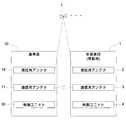
図2に示すように、作業車両1には、CPUや記憶装置等で構成された制御ユニット4と、基準局装置10の通信用アンテナ11との間で無線通信を行う通信用アンテナ3とが設けられている。一方、基準局装置10には、CPUや記憶装置等で構成された制御ユニット30と、作業車両1の通信用アンテナ3との間で無線通信を行う通信用アンテナ11とが設けられている。これら通信用アンテナ3,11の夫々は、ユーザが利用するタブレット型パーソナルコンピュータ等の携帯情報端末5(図1参照)との間でも、WiFi等を通じた無線通信が可能に構成されている。 As shown in FIG. 2, the
各無線通信に用いられる周波数帯域は、共通の周波数帯域であってもよいし、互いに異なる周波数帯域であってもよい。また、携帯情報端末5は、例えば、タッチパネルを有するタブレット型のパーソナルコンピュータ等から構成され、各種情報をタッチパネルに表示可能であり、タッチパネルを操作することで、各種の情報も入力可能となっている。携帯情報端末5は、ユーザが作業車両1の外部にて携帯して使用することが可能であると共に、作業車両1の運転席の側脇等に装着して使用することもできる。 The frequency band used for each wireless communication may be a common frequency band or may be a different frequency band from each other. Further, the
通信用アンテナ3,11により、作業車両1と基準局装置10との間でリアルタイムの情報の送受信が可能となる。更には、所定のアプリケーションソフトウェアを実行した携帯情報端末5を用いて、作業車両1を遠隔で操作することが可能となる。 The
作業車両1に設けられた制御ユニット4は、所定のコンピュータソフトウェアを実行することで、以下に説明する移動局測位処理、方位角特定処理、及び、自動走行制御等を実行する。 The
作業車両1側の制御ユニット4が実行する移動局測位処理は、作業車両1に設置された測位用アンテナ2にて測位衛星7から受信した測位信号と基準局装置10から受信した補正情報とに基づく測位を実行して、移動局である作業車両1の現在位置の緯度・経度等を示す移動局測位情報を求める処理として構成されている。 The mobile station positioning process executed by the
例えば、移動局測位処理により行われる測位としては、ディファレンシャル測位方式(DGPS測位方式)、リアルタイムキネマティック測位方式(RTK−GPS測位方式)等の各種の測位方法が適用される。
制御ユニット4は、例えば数秒毎に移動局測位処理による測位を繰り返し実行し、その測位により得られた移動局測位情報を、測位時の時間情報と関連付けて逐次保存する。For example, as the positioning performed by the mobile station positioning process, various positioning methods such as a differential positioning method (DGPS positioning method) and a real-time kinematic positioning method (RTK-GPS positioning method) are applied.
The
作業車両1側の制御ユニット4が実行する方位角特定処理は、作業車両1の移動に伴って移動局測位処理での測位により得られた移動局測位情報の変化状態から、作業車両1の方位角を求める処理として構成されている。 The azimuth angle identification process executed by the
例えば、方位角特定処理では、移動局測位処理により現在の移動局測位情報が得られた時点で、既に保存された直前の移動局測位情報を参照し、その直前の移動局測位情報から現在の移動局測位情報に向かう速度ベクトルの向きを、作業車両1の方位角として特定することができる。
尚、上記直前の移動局測位情報としては、保存された直前の移動局測位処理での測位により得られた移動局測位情報を用いることができるが、例えば作業車両1の走行開始時においては、単独測位又はユーザが入力して得られた移動局測位情報を用いることもできる。For example, in the azimuth identification process, when the current mobile station positioning information is obtained by the mobile station positioning process, the immediately preceding mobile station positioning information that has already been saved is referred to, and the current mobile station positioning information is used from the immediately preceding mobile station positioning information. The direction of the velocity vector toward the mobile station positioning information can be specified as the azimuth angle of the
As the mobile station positioning information immediately before the above, the mobile station positioning information obtained by the positioning in the mobile station positioning process immediately before being saved can be used, but for example, at the start of traveling of the
制御ユニット4は、例えば移動局測位処理による測位が実行される毎に作業車両1の方位角を逐次特定し、それにより得られた作業車両1の方位角を、特定時の時間情報と関連付けて逐次保存する。 The
作業車両1側の制御ユニット4が実行する自動走行制御は、移動局測位処理での測位により得られた移動局測位情報を用いて、予め定められた目標走行経路に沿った作業車両1の自動走行を実行する処理として構成されている。 The automatic driving control executed by the
例えば、携帯情報端末5において、作業車両1の自動走行に必要な目標走行経路などの情報がユーザにより生成され、その情報が、作業車両1側に送信されて保存される。そして、自動走行制御では、方位角特定処理で特定された作業車両1の方位角や、3軸のジャイロと3方向の加速度計等を有するIMU(Inertial Measurement Unit:慣性計測装置)で計測される作業車両1の姿勢等を適時参照しながら、作業車両1に装備されたエンジン制御装置、変速装置及び操舵装置等の各種装置を自動制御する。この自動制御により、移動局測位処理での測位により得られた移動局測位情報が示す作業車両1の現在位置が携帯情報端末5から受信した目標走行経路に沿ったものになるように、作業車両1の自動走行が実行される。 For example, in the
基準局装置10に設けられた制御ユニット30は、所定のコンピュータソフトウェアを実行することで、以下に説明する基準局測位処理、基準局登録処理、補正情報生成処理等を実行する。 The
基準局装置10側の制御ユニット30が実行する基準局測位処理は、基準局装置10に設置された測位用アンテナ19にて測位衛星7から受信した測位信号に基づく測位を実行して、基準局である基準局装置10の現在位置の緯度経度等を示す基準局測位情報を求める処理として構成されている。 The reference station positioning process executed by the
具体的に、基準局測位処理により行われる測位では、1つの測位用アンテナ19で受信した複数の測位衛星7から測位信号を解析して、それら夫々の測位信号の伝搬時間から、測位用アンテナ19の夫々の測位衛星7からの距離が求められる。このようにして得られた夫々の測位衛星7からの距離を解析することにより、測位用アンテナ19が設けられた基準局装置10の現在位置を示す基準局測位情報を求めることができる。例えば、基準局測位処理により行われる測位としては、1つの測位用アンテナ19で受信した複数の測位衛星7から測位信号を解析して、それら夫々の測位信号の伝搬時間から測位用アンテナ19の夫々の測位衛星7からの距離を求める単独測位方法が適用される。 Specifically, in the positioning performed by the reference station positioning process, the positioning signals are analyzed from the plurality of
基準局装置10側の制御ユニット30が実行する基準局登録処理は、固定位置に設置された基準局装置10の設置位置の緯度・経度等を示す基準局設置位置情報を登録するものとして構成されている。例えば、新規に基準局装置10を設置したり、基準局装置10の設置位置を変更した場合において、基準局登録処理により基準局設置情報の登録が実行される。
更に、基準局登録処理は、手動入力作業を省略しながら、正確な基準局設置位置情報を確実に登録するために、基準局装置10側で基準局装置10の設置位置を求めて自動的に登録する自動登録処理を実行可能に構成されている。The reference station registration process executed by the
Further, in the reference station registration process, in order to surely register accurate reference station installation position information while omitting the manual input work, the
基準局装置10側の制御ユニット30が実行する補正情報生成処理は、基準局装置10に設置された測位用アンテナ19にて測位衛星7から受信した測位信号と、基準局登録処理で予め登録された基準局設置位置情報とに基づいて、測位衛星7から受信される測位信号に対する補正情報を生成する処理として構成されている。 The correction information generation process executed by the
また、基準局装置10側の制御ユニット30は、例えば数秒毎に繰り返して補正情報生成処理により補正情報を生成し、その生成した補正情報を、通信用アンテナ3,11を通じてリアルタイムに作業車両1側に送信する。そして、作業車両1側の制御ユニット4では、基準局装置10側から受信した補正情報を、移動局測位処理におけるディファレンシャル測位方式又はリアルタイムキネマティック測位方式での測位に利用する。 Further, the
例えば、作業車両1側の移動局測位処理において、ディファレンシャル測位方式で測位を行う場合には、補正情報の取得対象となる基準局装置10の補正情報生成処理では、基準局登録処理で予め登録された基準局設置位置情報が示す基準局装置10の設置位置に対し、基準局測位処理での測位により得られた基準局測位情報が示す基準局装置10の設置位置の差分データを、補正情報として生成して、作業車両1側に送信する。 For example, in the mobile station positioning process on the
そして、作業車両1側の移動局測位処理において、ディファレンシャル測位方式で測位を行うにあたり、単独測位を実行して作業車両1の現在位置を求め、その単独測位により得られた現在位置を基準局装置10側から受信した差分データにより補正することで、作業車両1の正確な現在位置の緯度・経度等を示す移動局測位情報を求める。 Then, in the mobile station positioning process on the
また、作業車両1側の移動局測位処理において、リアルタイムキネマティック測位方式で測位を行う場合には、補正情報の取得対象となる基準局装置10の補正情報生成処理では、基準局登録処理で予め登録された基準局設置位置情報と、基準局装置10側の測位用アンテナ19で受信した測位信号の位相データとを、補正情報として生成して、作業車両1側に送信する。 Further, in the mobile station positioning process on the
そして、作業車両1側の移動局測位処理において、リアルタイムキネマティック測位方式で測位を行うにあたり、作業車両1側の測位用アンテナ2で受信した測位信号の位相データと、基準局装置10側の測位用アンテナ19で受信した測位信号の位相データとをリアルタイムで解析する。この解析により、基準局装置10の設置位置に対する作業車両1の現在位置の相対位置関係を求め、その相対位置関係と基準局設置位置情報とから、作業車両1の正確な現在位置の緯度・経度等を示す移動局測位情報を求める。 Then, in the mobile station positioning process on the
尚、本実施形態では、本発明に係る基準局装置10を自動走行システムに利用する例を説明したが、当該基準局装置10の用途は、これに限るものではない。また、自動走行システムにおいて実施される測位処理等の各種処理内容についても、適宜変更しても構わない。 In the present embodiment, an example of using the
(基準局装置)
次に、本実施形態の基準局装置10の構成について説明する。
図3に示すように、基準局装置10は、移動局としての作業車両1との間で無線通信を行う通信用アンテナ11と、測位衛星7から測位信号を受信する測位用アンテナ19と、測位用アンテナ19及び通信用アンテナ11の作動を制御する制御ユニット30とを備える。(Reference station equipment)
Next, the configuration of the
As shown in FIG. 3, the
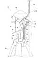
基準局装置10には、図5〜図8に示すように、地表面に立設される三脚等からなる支持脚体40により支持された基準局本体20が設けられている。この基準局本体20に制御ユニット30及び測位用アンテナ19が取り付けられている。
測位用アンテナ19については、約2Kgと比較的重量があるため、高所に設置すると安定しないという問題がある。そこで、本実施形態では、測位用アンテナ19は、制御ユニット30と共に基準局本体20に直接取り付けられて、支持脚体40の重心軸線上であって約1mと比較的低所に安定して設置されることになる。よって、高精度な測位が可能となる。As shown in FIGS. 5 to 8, the
Since the
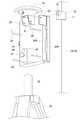
基準局本体20は、図7及び図8に示すように、制御ユニット30を内部に収容すると共に、当該制御ユニット30の前面側を開閉自在な開閉扉20Aを有する略箱状の筐体で構成されている。基準局本体20を構成する筐体は、支持脚体40により支持されて前面に制御ユニット30が固定されるベースプレート20Bと、その前面側に配置された箱状の開閉扉20Aとを有して構成されている。測位用アンテナ19は、図5に示すように、ベースプレート20Bの背面上端部側に固定されたブラケット21に対してネジにより取り付けられている。 As shown in FIGS. 7 and 8, the reference station
開閉扉20Aとベースプレート20Bとは、図8に示すように、側縁部同士が上下に配置された蝶番20Cを介して連結されている。そして、開閉扉20Aは、ベースプレート20Bの前面に対して側方に揺動して離間する開状態(図8参照)と、ベースプレート20Bの前面に近接する閉状態(図7参照)との間で、姿勢を変更して開閉自在となる。
よって、開閉扉20Aを開状態とすれば、図8に示すように、制御ユニット30の前面に設けられたキースイッチや電源スイッチなどの操作部30aに対する操作や液晶ディスプレイなどの表示部30bに対する視認を容易に行うことができる。一方、開閉扉20Aを閉状態とすれば、制御ユニット30の前面が箱状の開閉扉20Aにより覆われた状態となって、当該制御ユニット30への誤操作を防止しつつ、当該制御ユニット30の太陽光による劣化や雨や埃等による故障等を好適に抑制できる。As shown in FIG. 8, the opening /
Therefore, when the opening /
制御ユニット30の側面には、電源用のバッテリ30cが取り付けられている。開閉扉20Aを開状態とすれば、このバッテリ30cの交換が可能となる。
また、制御ユニット30の底面には、測位用アンテナ19や通信用アンテナ11等との間の配線Wを接続するためのコネクタ30d等が設けられている。そして、開閉扉20Aの底部が開放されていることから、開閉扉20Aの開閉操作において、このコネクタ30dに接続された配線Wが邪魔になることはない。
また、コネクタ30dの前方側には、閉状態とされた開閉扉20Aの下端部が存在し、コネクタ30dの後方側には、ベースプレート20Bの下端部が存在することになる。このことにより、基準局本体20が転倒した際でも、コネクタ30dから配線Wが外れ難くなる。A
Further, on the bottom surface of the
Further, the lower end portion of the open /
図6に示すように、基準局本体20のベースプレート20Bの背面には、測位用アンテナ19や通信用アンテナ11に接続される配線Wを巻き付け可能な棒状体からなる配線巻き付け部24が設けられている。よって、搬送時に測位用アンテナ19や通信用アンテナ11から取り外した配線Wや余剰の配線Wを邪魔にならないように配線巻き付け部24に巻き付けておくことができる。 As shown in FIG. 6, on the back surface of the
基準局本体20には、図5及び図6に示すように、支持脚体40に対して着脱自在に取り付けられる支持脚体取付部25が設けられている。支持脚体取付部25は、基準局本体20のベースプレート20Bの背面側に固定された角筒状のスリーブ部26を有する。このスリーブ部26が、支持脚体40の上端部に固定された円柱状の本体取付柱部42に対して上方から外嵌される状態で、基準局本体20が支持脚体40の上端部に取り付けられる。更に、スリーブ部26には、当該スリーブ部26に内挿される本体取付柱部42を固定するための固定用ネジ27が設けられている。この固定用ネジ27を緩めることで、基準局本体20を支持脚体40から取り外して搬送することができる。更に、本実施形態では、支持脚体40として三脚を用いているが、上記本体取付柱部42を有するものであれば、三脚の代わりに杭などの別の支持脚体を利用することもできる。 As shown in FIGS. 5 and 6, the reference station
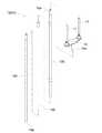
基準局装置10には、図3及び図4に示すように、通信用アンテナ11を基準局本体20よりも上方に支持する通信用アンテナ支持部12として、上下に延びる棒状の支持棒13が設けられている。この支持棒13により通信用アンテナ11を少なくとも基準局本体20よりも上方の約3mの高さに保持することで、作業車両1側の通信用アンテナ3との間の無線通信が、遮蔽物による通信障害が抑制された良好なものとなる。 As shown in FIGS. 3 and 4, the
支持棒13の上端部には、略T字形状のブラケット14が取り付けられている。一方、通信用アンテナ11の底部には比較的強力な磁石が取り付けられている。そして、一対の通信用アンテナ11が、支持棒13の上端部に取り付けられているブラケット14の上面の両端部に磁着により固定されている。
ブラケット14の下面の中央部にはスリーブ部14aが設けられている。このスリーブ部14aが支持棒13の上端部に形成された柱状の差込部13aに対して外嵌する状態で、通信用アンテナ11が支持棒13の上端部に対して着脱自在に取り付けられることになる。A substantially T-shaped
A
支持棒13は、図4に示すように、約1mの長さの3つの棒状の支持棒部材13A,13B,13Cを嵌め込み式で連結して構成されている。よって、支持棒13は、夫々の支持棒部材13A,13B,13Cに分割してコンパクトな状態で搬送することができる。 As shown in FIG. 4, the
基準局装置10には、図3、図5、及び図6に示すように、基準局本体20に対して通信用アンテナ支持部12を構成する支持棒13を着脱自在に取り付ける通信用アンテナ取付部16が設けられている。そして、通信用アンテナ取付部16は、基準局本体20の側方に設けられた支持棒13を当該支持棒13の下端部13bを地表面に当接させた状態で保持可能に構成されている。 As shown in FIGS. 3, 5, and 6, the
具体的に、通信用アンテナ取付部16は、基準局本体20のベースプレート20Bの側縁部に固定されたベースプレート22と、当該ベースプレート22と対向配置される押え部材17と、当該押え部材17をベースプレート22に対して近接させる状態で締結する固定用ネジ18とで構成されている。そして、下端部13bが地表面に当接した支持棒13をベースプレート22と押え部材17との間に配置した状態で、固定用ネジ18を締め付けることで、下端部13bが地表面に当接した支持棒13が基準局本体20の側面部に沿った状態で固定される。即ち、この構成では、ベースプレート22とそれに対して固定用ネジ18により固定された押え部材17との間には、基準局本体20に設けられて上下方向に延びる筒状空間が形成されることになる。そして、その基準局本体20側の筒状空間に対して、支持棒13を立ち姿勢で挿入して貫通させる状態で、当該支持棒13が、基準局本体20の側方において下端部13bを地表面に当接させた状態で保持されることになる。このように支持棒13を保持することで、通信用アンテナ11を適切な高さに支持しながら、支持棒13及びその上端部に取り付けられた通信用アンテナ11の姿勢を安定化させることができる。 Specifically, the communication
更に、支持棒13の下端部13bが地表面に当接しているので、支持棒13及び通信用アンテナ11の荷重は、基準局本体20ではなく、地表面に伝達される。よって、基準局本体20及びそれに取り付けられる測位用アンテナ19の姿勢についても安定化し、基準局本体20の転倒が抑制されつつ、測位用アンテナ19による測位の精度が一層向上することになる。
また、固定用ネジ18を緩めれば、支持棒13を基準局本体20から簡単に取り外して、基準局本体20とは別体で搬送することができる。Further, since the
Further, if the fixing
これまで説明したように基準局装置10は、制御ユニット30及び測位用アンテナ19が取り付けられた基準局本体20は、支持脚体40から取り外すと共に、通信用アンテナ11が取り付けられた通信用アンテナ支持部12としての支持棒13を取り外した状態で搬送可能となる。また、通信用アンテナ11についても、支持棒13から取り外した状態で搬送可能となる。
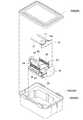
そして、これら基準局本体20と、通信用アンテナ11及びそれが固定されるブラケット14については、図9及び図10に示すように、所定の収納ボックス50に収納した状態で搬送することができる。
かかる収納ボックス50は、角容器状のボックス本体50Aと、その上面開口部を封鎖可能な蓋部材50Bと、ボックス本体50Aの内部を所望の形状の空間に規定するための充填材50Cとで構成されている。
そして、ボックス本体50Aの内部において充填材50Cで規定された空間に、基準局本体20を倒伏状態で収納し、その基準局本体20と重なる状態でブラケット14及びそれに固定された通信用アンテナ11を収納することができる。
また、このようなボックス本体50Aへの収納時では、ブラケット14においてスリーブ部14aが突出形成された面の両端部に通信用アンテナ11を磁着している。このことで、使用時のように、ブラケット14においてスリーブ部14aが突出形成された面とは反対側の面の両端部に通信用アンテナ11を磁着する場合と比較して、必要となる収納スペースをコンパクトにすることができる。As described above, in the
Then, the reference station
The
Then, the reference station
Further, when the
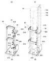
また、図11及び図12に示すように、基準局本体20が取り外された支持脚体40や通信用アンテナ11を支持するための支持棒13については、作業車両1に設けられたステップSに取り付けられた収納用枠体60に収納した状態で搬送することができる。
かかる収納用枠体60は、支持脚体40を直立姿勢で収納可能な支持脚体収納部61と、支持棒13を3つの支持棒部材13A,13B,13Cに分割した状態で夫々を直立姿勢で収納可能な支持棒部材収納部62とを有する。Further, as shown in FIGS. 11 and 12, the
The
支持脚体収納部61は、背面側に固定された固定枠61Aと、その固定枠61Aの前面側において開閉自在に支持された開閉枠61Bと、それらの下方側に設けられた筒状の先端支持部61Cとを有して構成されている。そして、この支持脚体収納部61に支持脚体40を収納する際には、先ずは、図11(a)示すように、開閉枠61Bを開状態とし、支持脚体40の下端部を先端支持部61Cに挿入する状態で、当該支持脚体40を直立姿勢で固定枠61Aの前面に立て掛け、次に、図11(b)に示すように、開閉枠61Bを閉状態とする。この状態にて、支持脚体40が直立姿勢で安定して保持されることになる。 The support
一方、支持棒部材収納部62は、上下方向に離間して配置された2つの支持プレート部62A、62Bを有し、これら支持プレート部62A、62Bには、夫々の支持棒部材13A,13B,13Cが上下方向に挿入される3つの挿通穴部62aが形成されている。また、下方側の支持プレート部62Bの下方側には、上記挿通穴部62aに挿入された支持棒部材13A,13B,13Cの下端部が当接する先端支持プレート部62Cが設けられている。そして、この支持棒部材収納部62に支持棒部材13A,13B,13Cを収納する際には、図11(b)示すように、支持棒部材13A,13B,13Cを上下の支持プレート部62A、62Bの各挿通穴部62aに上方から挿入し、その支持棒部材13A,13B,13Cの下端部を先端支持プレート部62Cに当接させる。この状態にて、支持棒部材13A,13B,13Cが直立姿勢で安定して保持されることになる。尚、下方側の支持プレート部62Bと先端支持プレート部62Cとは、コの字状の断面を有する板状部材にて一体的に構成されている。 On the other hand, the support rod
この収納用枠体60は、図12に示すように、支持脚体収納部61の先端支持部61Cが上面に設けられた底プレート部63とその下面側にボルト70及びナット71により固定可能な挟持プレート64との間でステップSを挟持する状態で、作業車両1のステップSに固定されている。よって、ステップSに対する収納用枠体60の着脱を容易に行うことができる。 As shown in FIG. 12, the
〔別実施形態〕
本発明の他の実施形態について説明する。尚、以下に説明する各実施形態の構成は、それぞれ単独で適用することに限らず、他の実施形態の構成と組み合わせて適用することも可能である。[Another Embodiment]
Other embodiments of the present invention will be described. It should be noted that the configurations of the respective embodiments described below are not limited to being applied independently, but can also be applied in combination with the configurations of other embodiments.
(1)上記実施形態では、基準局本体20を、制御ユニット30の前面側を開閉自在な開閉扉20Aを有する略箱状の筐体で構成したが、当該基準局本体20の構成については適宜改変可能であり、例えば、開閉扉20Aを省略し、制御ユニット30の前面側を開放するように構成しても構わない。(1) In the above embodiment, the reference station
(2)上記実施形態では、通信用アンテナ11を基準局本体20よりも上方に支持する通信用アンテナ支持部12としての支持棒13を、基準局本体20に対して、下端部13bが地表面に当接する状態で保持するように構成したが、例えば、支持棒13の下端部13bを、地表面に当接させずに浮かせた状態としたり、支持脚体40に保持させるように構成しても構わない。(2) In the above embodiment, the
(3)上記実施形態では、基準局本体20を、地表面に立設される支持脚体40に対して着脱自在に取り付けられる支持脚体取付部25を有するように構成したが、例えば、基準局本体20と支持脚体40とを分離不能に一体化しても構わない。また、この構成を採用する場合には、支持脚体40を折り畳み可能なものとして構成すれば、コンパクト化して容易に搬送することができる。(3) In the above embodiment, the reference station
1 作業車両(移動局)
7 測位衛星
10 基準局装置
11 通信用アンテナ
12 通信用アンテナ支持部
13 支持棒
13A 支持棒部材
13b 下端部
16 通信用アンテナ取付部
19 測位用アンテナ
20 基準局本体
20A 開閉扉
25 支持脚体取付部
30 制御ユニット
40 支持脚体
1 Work vehicle (mobile station)
7 Positioning
Claims (3)
Translated fromJapanese測位衛星から測位信号を受信する測位用アンテナと、
前記測位用アンテナ及び前記通信用アンテナの作動を制御する制御ユニットと、を備えた基準局装置であって、
前記制御ユニット及び前記測位用アンテナが取り付けられて地表面に支持される基準局本体と、
前記通信用アンテナを前記測位用アンテナよりも上方位置に支持する通信用アンテナ支持部と、
前記基準局本体に対して前記通信用アンテナ支持部を着脱自在に取り付ける通信用アンテナ取付部と、を備え、
前記基準局本体が、前記制御ユニットを内部に収容すると共に、
当該制御ユニットが前面に固定されるベースプレートと、
当該制御ユニットの前面側を開閉自在な開閉扉と、を有し、
前記測位用アンテナが、前記ベースプレートの背面側に取り付けられる基準局装置。A communication antenna for wireless communication with a mobile station,
A positioning antenna that receives positioning signals from positioning satellites, and
A reference station device including the positioning antenna and a control unit that controls the operation of the communication antenna.
A reference station body to which the control unit and the positioning antenna are attached and supported on the ground surface,
A communication antenna support portion that supports the communication antenna at a position above the positioning antenna, and a communication antenna support portion.
A communication antenna attachment portion for detachably attaching the communication antenna support portion to the reference station main body is provided.
The reference station main body accommodates the control unit inside and at the same time.
The base plate on which the control unit is fixed to the front and
It has an open / close door that can open and close the front side of the control unit.
A reference station device in which thepositioning antenna is attached to the back side of the base plate.
前記通信用アンテナ取付部が、前記基準局本体の側方に設けられた前記支持棒を当該支持棒の下端部を地表面に当接させた状態で保持可能に構成されている請求項1に記載の基準局装置。The communication antenna support portion is composed of a support rod extending vertically, and the communication antenna is detachably attached to the upper end portion of the support rod.
The communication antenna mounting portion, according toclaim 1 which is configured to be hold the support rod that is provided on the side of the reference station body being in contact with the lower end of the support bar on the ground surface Reference station equipment.
Priority Applications (7)
| Application Number | Priority Date | Filing Date | Title |
|---|---|---|---|
| JP2018020903AJP6879957B2 (en) | 2018-02-08 | 2018-02-08 | Reference station equipment |
| CN201980006915.4ACN111670386A (en) | 2018-02-08 | 2019-01-09 | base station device |
| KR1020207007873AKR20200119228A (en) | 2018-02-08 | 2019-01-09 | Reference station device |
| US16/968,163US20210041575A1 (en) | 2018-02-08 | 2019-01-09 | Reference Station Device |
| PCT/JP2019/000352WO2019155812A1 (en) | 2018-02-08 | 2019-01-09 | Reference station device |
| EP19750694.2AEP3751314A4 (en) | 2018-02-08 | 2019-01-09 | Reference station device |
| JP2021076988AJP2021119353A (en) | 2018-02-08 | 2021-04-30 | Reference station device |
Applications Claiming Priority (1)
| Application Number | Priority Date | Filing Date | Title |
|---|---|---|---|
| JP2018020903AJP6879957B2 (en) | 2018-02-08 | 2018-02-08 | Reference station equipment |
Related Child Applications (1)
| Application Number | Title | Priority Date | Filing Date |
|---|---|---|---|
| JP2021076988ADivisionJP2021119353A (en) | 2018-02-08 | 2021-04-30 | Reference station device |
Publications (2)
| Publication Number | Publication Date |
|---|---|
| JP2019138727A JP2019138727A (en) | 2019-08-22 |
| JP6879957B2true JP6879957B2 (en) | 2021-06-02 |
Family
ID=67548426
Family Applications (2)
| Application Number | Title | Priority Date | Filing Date |
|---|---|---|---|
| JP2018020903AActiveJP6879957B2 (en) | 2018-02-08 | 2018-02-08 | Reference station equipment |
| JP2021076988APendingJP2021119353A (en) | 2018-02-08 | 2021-04-30 | Reference station device |
Family Applications After (1)
| Application Number | Title | Priority Date | Filing Date |
|---|---|---|---|
| JP2021076988APendingJP2021119353A (en) | 2018-02-08 | 2021-04-30 | Reference station device |
Country Status (6)
| Country | Link |
|---|---|
| US (1) | US20210041575A1 (en) |
| EP (1) | EP3751314A4 (en) |
| JP (2) | JP6879957B2 (en) |
| KR (1) | KR20200119228A (en) |
| CN (1) | CN111670386A (en) |
| WO (1) | WO2019155812A1 (en) |
Families Citing this family (4)
| Publication number | Priority date | Publication date | Assignee | Title |
|---|---|---|---|---|
| JP7507566B2 (en)* | 2020-01-30 | 2024-06-28 | 日本無線株式会社 | Wireless communication unit |
| JP7514083B2 (en)* | 2020-01-30 | 2024-07-10 | 日本無線株式会社 | Wireless communication unit |
| CN113840397A (en)* | 2021-11-15 | 2021-12-24 | 南京苏美达智能技术有限公司 | Self-walking equipment base station capable of automatically adjusting height of antenna based on signal intensity |
| WO2024224952A1 (en)* | 2023-04-28 | 2024-10-31 | ソニーグループ株式会社 | Information processing method, fixed station, and program |
Family Cites Families (19)
| Publication number | Priority date | Publication date | Assignee | Title |
|---|---|---|---|---|
| JPH05217570A (en)* | 1992-02-04 | 1993-08-27 | Topcon Corp | Electronic equipment power supply |
| JPH0793530B2 (en)* | 1992-04-20 | 1995-10-09 | 三井建設株式会社 | GPS antenna holder |
| JP3273823B2 (en)* | 1993-03-22 | 2002-04-15 | 株式会社ソキア | GPS receiver for surveying |
| JPH1020013A (en)* | 1996-07-09 | 1998-01-23 | Harada Ind Co Ltd | Portable DGPS receiver |
| US6072429A (en)* | 1997-01-31 | 2000-06-06 | Trimble Navigation Limited | Integrated position determination system and radio transceiver incorporating common components |
| JPH11177323A (en)* | 1997-12-05 | 1999-07-02 | Mitsui Constr Co Ltd | Gps antenna support pole and pole unit used to the pole |
| JP2001188082A (en)* | 1998-08-20 | 2001-07-10 | Trimble Navigation Ltd | Integral position determination system provided with radio relay device |
| JP3875443B2 (en)* | 2000-02-15 | 2007-01-31 | 株式会社和光測機 | Surveying pole and GPS surveying mobile station antenna holding device |
| JP3641582B2 (en)* | 2000-10-27 | 2005-04-20 | 日本無線株式会社 | ADE unit for AIS |
| CN2777572Y (en)* | 2005-01-20 | 2006-05-03 | 北京合众思壮科技有限责任公司 | Satellite positioning apparatus |
| JP2006299532A (en)* | 2005-04-15 | 2006-11-02 | Kg Mark Co Ltd | Emergency box |
| JP4772551B2 (en) | 2006-03-24 | 2011-09-14 | 株式会社エヌ・ティ・ティ・ドコモ | Portable base station apparatus and billing method |
| US8686899B2 (en)* | 2010-08-26 | 2014-04-01 | Hemisphere GNSS, Inc. | GNSS smart antenna and receiver system with weatherproof enclosure |
| JP2013005300A (en)* | 2011-06-17 | 2013-01-07 | Cosmo System Kk | Communication instrument frame and radio base station |
| JP2014085168A (en) | 2012-10-22 | 2014-05-12 | Nagata Denki Kk | Position measurement system |
| JP2016095660A (en)* | 2014-11-13 | 2016-05-26 | ヤンマー株式会社 | Unmanned operation system |
| US10478668B2 (en)* | 2014-11-24 | 2019-11-19 | Adidas Ag | Activity monitoring base station |
| WO2017148438A1 (en)* | 2016-03-03 | 2017-09-08 | 苏州宝时得电动工具有限公司 | Precise positioning system, and base station and self-movable robot system thereof |
| JP6679508B2 (en)* | 2017-01-18 | 2020-04-15 | ヤンマー株式会社 | Base station |
- 2018
- 2018-02-08JPJP2018020903Apatent/JP6879957B2/enactiveActive
- 2019
- 2019-01-09USUS16/968,163patent/US20210041575A1/ennot_activeAbandoned
- 2019-01-09CNCN201980006915.4Apatent/CN111670386A/enactivePending
- 2019-01-09WOPCT/JP2019/000352patent/WO2019155812A1/ennot_activeCeased
- 2019-01-09EPEP19750694.2Apatent/EP3751314A4/ennot_activeWithdrawn
- 2019-01-09KRKR1020207007873Apatent/KR20200119228A/ennot_activeCeased
- 2021
- 2021-04-30JPJP2021076988Apatent/JP2021119353A/enactivePending
Also Published As
| Publication number | Publication date |
|---|---|
| JP2019138727A (en) | 2019-08-22 |
| EP3751314A1 (en) | 2020-12-16 |
| WO2019155812A1 (en) | 2019-08-15 |
| CN111670386A (en) | 2020-09-15 |
| EP3751314A4 (en) | 2021-11-10 |
| US20210041575A1 (en) | 2021-02-11 |
| KR20200119228A (en) | 2020-10-19 |
| JP2021119353A (en) | 2021-08-12 |
Similar Documents
| Publication | Publication Date | Title |
|---|---|---|
| JP2021119353A (en) | Reference station device | |
| US20230127868A1 (en) | Antenna Unit for Work Vehicle and Work Vehicle | |
| JP7422909B2 (en) | work vehicle | |
| JP7736854B2 (en) | Work vehicles | |
| US20210199438A1 (en) | Heading initialization method for tilt rtk | |
| JP7596469B2 (en) | Work vehicles | |
| KR102688700B1 (en) | Work vehicle antenna unit and work vehicle | |
| JP7727048B2 (en) | Work vehicles | |
| JP2006056280A (en) | Working vehicle | |
| US20250042469A1 (en) | Vehicle Control Method and Apparatus, Controller, System, and Storage Medium | |
| EP4246273B1 (en) | Modular sensor kit for the collection of vehicle-related data | |
| JP6866235B2 (en) | Positioning device | |
| JP2025157616A (en) | Work vehicles |
Legal Events
| Date | Code | Title | Description |
|---|---|---|---|
| A621 | Written request for application examination | Free format text:JAPANESE INTERMEDIATE CODE: A621 Effective date:20200130 | |
| A131 | Notification of reasons for refusal | Free format text:JAPANESE INTERMEDIATE CODE: A131 Effective date:20200701 | |
| RD03 | Notification of appointment of power of attorney | Free format text:JAPANESE INTERMEDIATE CODE: A7423 Effective date:20200713 | |
| RD03 | Notification of appointment of power of attorney | Free format text:JAPANESE INTERMEDIATE CODE: A7423 Effective date:20200814 | |
| A521 | Written amendment | Free format text:JAPANESE INTERMEDIATE CODE: A523 Effective date:20200826 | |
| A131 | Notification of reasons for refusal | Free format text:JAPANESE INTERMEDIATE CODE: A131 Effective date:20210112 | |
| A521 | Written amendment | Free format text:JAPANESE INTERMEDIATE CODE: A523 Effective date:20210311 | |
| TRDD | Decision of grant or rejection written | ||
| A01 | Written decision to grant a patent or to grant a registration (utility model) | Free format text:JAPANESE INTERMEDIATE CODE: A01 Effective date:20210330 | |
| A61 | First payment of annual fees (during grant procedure) | Free format text:JAPANESE INTERMEDIATE CODE: A61 Effective date:20210430 | |
| R150 | Certificate of patent or registration of utility model | Ref document number:6879957 Country of ref document:JP Free format text:JAPANESE INTERMEDIATE CODE: R150 |