JP6879792B2 - Metal detector for detecting the insertion of surgical instruments into hollow tubes - Google Patents
Metal detector for detecting the insertion of surgical instruments into hollow tubesDownload PDFInfo
- Publication number
- JP6879792B2 JP6879792B2JP2017048213AJP2017048213AJP6879792B2JP 6879792 B2JP6879792 B2JP 6879792B2JP 2017048213 AJP2017048213 AJP 2017048213AJP 2017048213 AJP2017048213 AJP 2017048213AJP 6879792 B2JP6879792 B2JP 6879792B2
- Authority
- JP
- Japan
- Prior art keywords
- pat
- metal
- patent publication
- robot
- waveform
- Prior art date
- Legal status (The legal status is an assumption and is not a legal conclusion. Google has not performed a legal analysis and makes no representation as to the accuracy of the status listed.)
- Active
Links
- 229910052751metalInorganic materials0.000titleclaimsdescription110
- 239000002184metalSubstances0.000titleclaimsdescription110
- 238000003780insertionMethods0.000titleclaimsdescription23
- 230000037431insertionEffects0.000titleclaimsdescription23
- 239000003990capacitorSubstances0.000claimsdescription21
- 238000013016dampingMethods0.000claimsdescription4
- 230000000630rising effectEffects0.000claims1
- 239000012636effectorSubstances0.000description68
- 238000000034methodMethods0.000description41
- 238000003384imaging methodMethods0.000description20
- 238000001514detection methodMethods0.000description19
- 239000000463materialSubstances0.000description18
- 230000005484gravityEffects0.000description15
- 230000006870functionEffects0.000description12
- 229920000049Carbon (fiber)Polymers0.000description9
- 239000004033plasticSubstances0.000description9
- 229920003023plasticPolymers0.000description9
- RTAQQCXQSZGOHL-UHFFFAOYSA-NTitaniumChemical compound[Ti]RTAQQCXQSZGOHL-UHFFFAOYSA-N0.000description8
- 239000004917carbon fiberSubstances0.000description8
- 238000004891communicationMethods0.000description8
- 150000002739metalsChemical class0.000description8
- VNWKTOKETHGBQD-UHFFFAOYSA-NmethaneChemical compoundCVNWKTOKETHGBQD-UHFFFAOYSA-N0.000description8
- 229910001220stainless steelInorganic materials0.000description8
- 239000010935stainless steelSubstances0.000description8
- 239000010936titaniumSubstances0.000description8
- 229910052719titaniumInorganic materials0.000description8
- 229910052782aluminiumInorganic materials0.000description7
- XAGFODPZIPBFFR-UHFFFAOYSA-NaluminiumChemical compound[Al]XAGFODPZIPBFFR-UHFFFAOYSA-N0.000description7
- 230000008859changeEffects0.000description6
- 239000011152fibreglassSubstances0.000description6
- 230000005291magnetic effectEffects0.000description6
- 238000001356surgical procedureMethods0.000description6
- 238000003825pressingMethods0.000description5
- 238000002591computed tomographyMethods0.000description4
- 238000010586diagramMethods0.000description4
- 238000012986modificationMethods0.000description4
- 230000004048modificationEffects0.000description4
- 230000005855radiationEffects0.000description4
- 230000001953sensory effectEffects0.000description4
- 230000004913activationEffects0.000description3
- 238000013500data storageMethods0.000description3
- 230000004907fluxEffects0.000description3
- 239000003292glueSubstances0.000description3
- 230000008569processEffects0.000description3
- 230000035945sensitivityEffects0.000description3
- 239000000853adhesiveSubstances0.000description2
- 230000001070adhesive effectEffects0.000description2
- -1but not limited toSubstances0.000description2
- 230000006698inductionEffects0.000description2
- 230000010354integrationEffects0.000description2
- 239000003550markerSubstances0.000description2
- 229920001084poly(chloroprene)Polymers0.000description2
- 241001631457CannulaSpecies0.000description1
- 210000003484anatomyAnatomy0.000description1
- 238000003491arrayMethods0.000description1
- 230000009286beneficial effectEffects0.000description1
- 210000000988bone and boneAnatomy0.000description1
- 238000004364calculation methodMethods0.000description1
- 238000012512characterization methodMethods0.000description1
- 238000006243chemical reactionMethods0.000description1
- 238000012790confirmationMethods0.000description1
- 230000008602contractionEffects0.000description1
- 238000007796conventional methodMethods0.000description1
- 230000000994depressogenic effectEffects0.000description1
- 230000000694effectsEffects0.000description1
- 229920001971elastomerPolymers0.000description1
- 230000005284excitationEffects0.000description1
- 238000002474experimental methodMethods0.000description1
- 239000004744fabricSubstances0.000description1
- 239000000499gelSubstances0.000description1
- 239000003365glass fiberSubstances0.000description1
- 238000013152interventional procedureMethods0.000description1
- 238000012423maintenanceMethods0.000description1
- 230000007246mechanismEffects0.000description1
- 230000005055memory storageEffects0.000description1
- 230000003287optical effectEffects0.000description1
- 210000000056organAnatomy0.000description1
- 230000002980postoperative effectEffects0.000description1
- 238000012545processingMethods0.000description1
- 230000010349pulsationEffects0.000description1
- 229920005989resinPolymers0.000description1
- 239000011347resinSubstances0.000description1
- 230000006641stabilisationEffects0.000description1
- 238000011105stabilizationMethods0.000description1
- 239000012780transparent materialSubstances0.000description1
- 239000002699waste materialSubstances0.000description1
- 229910000859α-FeInorganic materials0.000description1
Images


Classifications
- A—HUMAN NECESSITIES
- A61—MEDICAL OR VETERINARY SCIENCE; HYGIENE
- A61B—DIAGNOSIS; SURGERY; IDENTIFICATION
- A61B34/00—Computer-aided surgery; Manipulators or robots specially adapted for use in surgery
- A61B34/20—Surgical navigation systems; Devices for tracking or guiding surgical instruments, e.g. for frameless stereotaxis
- G—PHYSICS
- G01—MEASURING; TESTING
- G01D—MEASURING NOT SPECIALLY ADAPTED FOR A SPECIFIC VARIABLE; ARRANGEMENTS FOR MEASURING TWO OR MORE VARIABLES NOT COVERED IN A SINGLE OTHER SUBCLASS; TARIFF METERING APPARATUS; MEASURING OR TESTING NOT OTHERWISE PROVIDED FOR
- G01D5/00—Mechanical means for transferring the output of a sensing member; Means for converting the output of a sensing member to another variable where the form or nature of the sensing member does not constrain the means for converting; Transducers not specially adapted for a specific variable
- G01D5/12—Mechanical means for transferring the output of a sensing member; Means for converting the output of a sensing member to another variable where the form or nature of the sensing member does not constrain the means for converting; Transducers not specially adapted for a specific variable using electric or magnetic means
- G01D5/14—Mechanical means for transferring the output of a sensing member; Means for converting the output of a sensing member to another variable where the form or nature of the sensing member does not constrain the means for converting; Transducers not specially adapted for a specific variable using electric or magnetic means influencing the magnitude of a current or voltage
- G01D5/20—Mechanical means for transferring the output of a sensing member; Means for converting the output of a sensing member to another variable where the form or nature of the sensing member does not constrain the means for converting; Transducers not specially adapted for a specific variable using electric or magnetic means influencing the magnitude of a current or voltage by varying inductance, e.g. by a movable armature
- A—HUMAN NECESSITIES
- A61—MEDICAL OR VETERINARY SCIENCE; HYGIENE
- A61B—DIAGNOSIS; SURGERY; IDENTIFICATION
- A61B17/00—Surgical instruments, devices or methods
- A61B17/16—Instruments for performing osteoclasis; Drills or chisels for bones; Trepans
- A61B17/17—Guides or aligning means for drills, mills, pins or wires
- A61B17/1703—Guides or aligning means for drills, mills, pins or wires using imaging means, e.g. by X-rays
- A—HUMAN NECESSITIES
- A61—MEDICAL OR VETERINARY SCIENCE; HYGIENE
- A61B—DIAGNOSIS; SURGERY; IDENTIFICATION
- A61B34/00—Computer-aided surgery; Manipulators or robots specially adapted for use in surgery
- A61B34/70—Manipulators specially adapted for use in surgery
- A—HUMAN NECESSITIES
- A61—MEDICAL OR VETERINARY SCIENCE; HYGIENE
- A61B—DIAGNOSIS; SURGERY; IDENTIFICATION
- A61B6/00—Apparatus or devices for radiation diagnosis; Apparatus or devices for radiation diagnosis combined with radiation therapy equipment
- A61B6/02—Arrangements for diagnosis sequentially in different planes; Stereoscopic radiation diagnosis
- A61B6/03—Computed tomography [CT]
- A61B6/032—Transmission computed tomography [CT]
- A—HUMAN NECESSITIES
- A61—MEDICAL OR VETERINARY SCIENCE; HYGIENE
- A61B—DIAGNOSIS; SURGERY; IDENTIFICATION
- A61B34/00—Computer-aided surgery; Manipulators or robots specially adapted for use in surgery
- A61B34/20—Surgical navigation systems; Devices for tracking or guiding surgical instruments, e.g. for frameless stereotaxis
- A61B2034/2046—Tracking techniques
- A61B2034/2051—Electromagnetic tracking systems
- A—HUMAN NECESSITIES
- A61—MEDICAL OR VETERINARY SCIENCE; HYGIENE
- A61B—DIAGNOSIS; SURGERY; IDENTIFICATION
- A61B34/00—Computer-aided surgery; Manipulators or robots specially adapted for use in surgery
- A61B34/20—Surgical navigation systems; Devices for tracking or guiding surgical instruments, e.g. for frameless stereotaxis
- A61B2034/2046—Tracking techniques
- A61B2034/2055—Optical tracking systems
- A61B2034/2057—Details of tracking cameras
- A—HUMAN NECESSITIES
- A61—MEDICAL OR VETERINARY SCIENCE; HYGIENE
- A61B—DIAGNOSIS; SURGERY; IDENTIFICATION
- A61B34/00—Computer-aided surgery; Manipulators or robots specially adapted for use in surgery
- A61B34/20—Surgical navigation systems; Devices for tracking or guiding surgical instruments, e.g. for frameless stereotaxis
- A61B2034/2046—Tracking techniques
- A61B2034/2065—Tracking using image or pattern recognition
- A—HUMAN NECESSITIES
- A61—MEDICAL OR VETERINARY SCIENCE; HYGIENE
- A61B—DIAGNOSIS; SURGERY; IDENTIFICATION
- A61B34/00—Computer-aided surgery; Manipulators or robots specially adapted for use in surgery
- A61B34/30—Surgical robots
- A61B2034/301—Surgical robots for introducing or steering flexible instruments inserted into the body, e.g. catheters or endoscopes
- A—HUMAN NECESSITIES
- A61—MEDICAL OR VETERINARY SCIENCE; HYGIENE
- A61B—DIAGNOSIS; SURGERY; IDENTIFICATION
- A61B34/00—Computer-aided surgery; Manipulators or robots specially adapted for use in surgery
- A61B34/30—Surgical robots
- A61B2034/305—Details of wrist mechanisms at distal ends of robotic arms
- A—HUMAN NECESSITIES
- A61—MEDICAL OR VETERINARY SCIENCE; HYGIENE
- A61B—DIAGNOSIS; SURGERY; IDENTIFICATION
- A61B90/00—Instruments, implements or accessories specially adapted for surgery or diagnosis and not covered by any of the groups A61B1/00 - A61B50/00, e.g. for luxation treatment or for protecting wound edges
- A61B90/06—Measuring instruments not otherwise provided for
- A61B2090/062—Measuring instruments not otherwise provided for penetration depth
- A—HUMAN NECESSITIES
- A61—MEDICAL OR VETERINARY SCIENCE; HYGIENE
- A61B—DIAGNOSIS; SURGERY; IDENTIFICATION
- A61B90/00—Instruments, implements or accessories specially adapted for surgery or diagnosis and not covered by any of the groups A61B1/00 - A61B50/00, e.g. for luxation treatment or for protecting wound edges
- A61B90/08—Accessories or related features not otherwise provided for
- A61B2090/0804—Counting number of instruments used; Instrument detectors
- A—HUMAN NECESSITIES
- A61—MEDICAL OR VETERINARY SCIENCE; HYGIENE
- A61B—DIAGNOSIS; SURGERY; IDENTIFICATION
- A61B90/00—Instruments, implements or accessories specially adapted for surgery or diagnosis and not covered by any of the groups A61B1/00 - A61B50/00, e.g. for luxation treatment or for protecting wound edges
- A61B90/36—Image-producing devices or illumination devices not otherwise provided for
- A61B90/37—Surgical systems with images on a monitor during operation
- A61B2090/376—Surgical systems with images on a monitor during operation using X-rays, e.g. fluoroscopy
- A—HUMAN NECESSITIES
- A61—MEDICAL OR VETERINARY SCIENCE; HYGIENE
- A61B—DIAGNOSIS; SURGERY; IDENTIFICATION
- A61B90/00—Instruments, implements or accessories specially adapted for surgery or diagnosis and not covered by any of the groups A61B1/00 - A61B50/00, e.g. for luxation treatment or for protecting wound edges
- A61B90/39—Markers, e.g. radio-opaque or breast lesions markers
- A61B2090/3966—Radiopaque markers visible in an X-ray image
- A—HUMAN NECESSITIES
- A61—MEDICAL OR VETERINARY SCIENCE; HYGIENE
- A61B—DIAGNOSIS; SURGERY; IDENTIFICATION
- A61B34/00—Computer-aided surgery; Manipulators or robots specially adapted for use in surgery
- A61B34/30—Surgical robots
Landscapes
- Health & Medical Sciences (AREA)
- Life Sciences & Earth Sciences (AREA)
- Engineering & Computer Science (AREA)
- Surgery (AREA)
- Medical Informatics (AREA)
- Nuclear Medicine, Radiotherapy & Molecular Imaging (AREA)
- Public Health (AREA)
- Heart & Thoracic Surgery (AREA)
- Biomedical Technology (AREA)
- Molecular Biology (AREA)
- Animal Behavior & Ethology (AREA)
- General Health & Medical Sciences (AREA)
- Veterinary Medicine (AREA)
- Robotics (AREA)
- Pathology (AREA)
- Radiology & Medical Imaging (AREA)
- Physics & Mathematics (AREA)
- Oral & Maxillofacial Surgery (AREA)
- Orthopedic Medicine & Surgery (AREA)
- Pulmonology (AREA)
- Theoretical Computer Science (AREA)
- Dentistry (AREA)
- Biophysics (AREA)
- High Energy & Nuclear Physics (AREA)
- Optics & Photonics (AREA)
- General Physics & Mathematics (AREA)
- Manipulator (AREA)
Description
Translated fromJapanese本発明は、金属検出器、システム、及び方法に関し、具体的には、金属手術器械を検出するための金属検出器に関する。 The present invention relates to metal detectors, systems, and methods, specifically metal detectors for detecting metal surgical instruments.
従来の金属検出器は、常にオンにされ、共振回路内のインダクタの電磁気特性、例えばQ値の変化を検出する電力消費型共振回路を使用する。金属片が共振回路の近くにあるとき、金属検出器はQ値の変化を検出して金属が見つかったかどうかを判断する。 Conventional metal detectors use a power-consuming resonant circuit that is always on and detects changes in the electromagnetic properties of the inductor in the resonant circuit, such as the Q value. When a piece of metal is near the resonant circuit, the metal detector detects a change in the Q value to determine if metal has been found.
このような従来の金属検出器の1つの問題は、共振回路が常にオンであるため、検出器が相当量の電力を無駄にする可能性があることである。携帯型ロボットを使用して医療処置を実行するというコンテキストでは、可能な限り小さな電力を使用することが重要である。したがって、金属の存在をより効率的に検出するための器具及び方法を提供する必要がある。 One problem with such conventional metal detectors is that the resonator can waste a significant amount of power because the resonant circuit is always on. In the context of performing medical procedures using portable robots, it is important to use as little power as possible. Therefore, it is necessary to provide an instrument and a method for more efficiently detecting the presence of a metal.
本発明の一態様によれば、中空管への金属手術器具の挿入を検出するための金属検出器が提供される。金属検出器は、スイッチ、共振回路、及び制御器を含む。共振回路は、コンデンサと、コンデンサに並列に接続されたコイルとを含む。コイルは、中空管に取り付けられている。制御器は、共振回路に一時的に電流を供給するために予め選択された時間の間、スイッチをオンにするように適合され、スイッチがオフにされたときに共振回路から生じる、結果として生じる減衰電圧波形を解析して、中空管内の金属手術器具の存在を決定する。 According to one aspect of the invention, there is provided a metal detector for detecting the insertion of a metal surgical instrument into a hollow tube. Metal detectors include switches, resonant circuits, and controllers. The resonant circuit includes a capacitor and a coil connected in parallel to the capacitor. The coil is attached to a hollow tube. The controller is adapted to switch on for a preselected amount of time to temporarily supply current to the resonant circuit and results from the resonant circuit when the switch is turned off. The decay voltage waveform is analyzed to determine the presence of metal surgical instruments in the hollow tube.
本発明の別の態様によれば、中空管への金属手術器具の挿入を検出する方法が提供される。最初に、コンデンサ及び中空管に取り付けられたインダクタを有する共振回路に電源が接続される。予め選択された時間間隔の後、電源は共振回路から切断される。電源が切断されると、共振回路は減衰波形を生成する。減衰波形は、金属手術器具が中空管に挿入されたか否かによって異なる形状を有する。生成された減衰波形に基づいて、中空管内の金属手術器具の存在が次に決定される。 According to another aspect of the invention, there is provided a method of detecting the insertion of a metal surgical instrument into a hollow tube. First, the power supply is connected to a resonant circuit with a capacitor and an inductor mounted in a hollow tube. After a preselected time interval, the power supply is disconnected from the resonant circuit. When the power is turned off, the resonant circuit produces an attenuation waveform. The decay waveform has a different shape depending on whether the metal surgical instrument is inserted into the hollow tube. Based on the generated decay waveform, the presence of metal surgical instruments in the hollow tube is then determined.
短い時間間隔の間だけ共振回路に電流を供給することにより、本発明は電力を有利に節約する。さらに、スイッチオン期間を調整するこの能力は、インダクタの種々のプリチャージレベル、またはボルト秒の積、または磁束を可能にする。 By supplying current to the resonant circuit only for short time intervals, the present invention advantageously saves power. In addition, this ability to adjust the switch-on period allows for various precharge levels of inductors, or products of volt seconds, or magnetic flux.
簡潔には、本発明の金属検出システムは、中空管の周りに位置決めされたインダクタに電流を供給するために非常に短い時間間隔の間共振回路をオンに切り替え、インダクタへの電流が遮断されると結果として生じる減衰波形を次に解析する。自然に振動する減衰波形を解析して、金属物体が中空管内にあるかどうかを検出することができる。さらに、減衰波形は、中空管内の金属物体の挿入深さを決定するためにも使用することができる。 Briefly, the metal detection system of the present invention turns on the resonant circuit for a very short time interval to supply current to the inductor positioned around the hollow tube, interrupting the current to the inductor. Then, the resulting attenuation waveform is analyzed next. It is possible to analyze the naturally oscillating damping waveform to detect whether a metal object is inside a hollow tube. In addition, the damping waveform can also be used to determine the insertion depth of metal objects in the hollow tube.
本技術は、従来の方法に比べていくつかの利点を有する。第1に、比較的高い信号対雑音比(SNR)及びインダクタンス感度を得るためには小さな初期エネルギーが必要とされるので、エネルギーはほとんど必要ない。第2に、スイッチSW1のオン時間を調整することによって、初期エネルギーが容易に調整される。これはインダクタLの初期磁束を設定し、これにより可変感度を可能にする。これは、共振回路が電気的に過酷な環境にある場合、必要な誘導感度を動的に変更することができる。励振の周波数またはコイルのリンギングは、より多くのサンプルを取ることができるように動的に調節することもできる。これらの値は、より良いSNRを得るために平均化することができる。 This technique has several advantages over conventional methods. First, little energy is required because a small initial energy is required to obtain a relatively high signal-to-noise ratio (SNR) and inductance sensitivity. Secondly, the initial energy is easily adjusted by adjusting the on time of the switch SW1. This sets the initial magnetic flux of the inductor L, which allows variable sensitivity. This allows the required induction sensitivity to be dynamically changed when the resonant circuit is in an electrically harsh environment. The excitation frequency or coil ringing can also be dynamically adjusted to allow more samples to be taken. These values can be averaged to get a better SNR.
図1〜図14は、図15〜図22を参照して説明する本金属検出器を組み込むことができるロボットシステムを説明する。 1 to 14 describe a robot system to which the metal detector described with reference to FIGS. 15 to 22 can be incorporated.
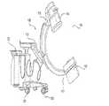
図1は、自動医療システム2の実施形態を示す。侵襲的医療処置の実施に先立って、患者の所望の手術領域の3次元(「3D」)画像スキャンを行い、自動医療システム2と通信するコンピュータプラットフォームに送信することができる。いくつかの実施形態では、医師は、患者の体内または体の上の所望の解剖学的標的に手術器械が到達するための所望の挿入点及び軌跡を次にプログラムすることができる。いくつかの実施形態では、3D画像スキャン上に所望の挿入点及び軌跡を計画することができ、いくつかの実施形態で、これをディスプレイ上に表示することができる。いくつかの実施形態では、医師は、患者のコンピュータ断層撮影スキャン(以下、「CTスキャン」と呼ぶ)上に軌道及び所望の挿入点(もしあれば)を計画することができる。いくつかの実施形態では、CTスキャンは、同心円Cアーム型スキャン、または任意の他の同様のタイプのスキャン、または当技術分野で知られている術中CTスキャンであってもよい。しかし、いくつかの実施形態では、自動医療システム2の実施形態に従って、任意の既知の3D画像スキャンを使用することができる。 FIG. 1 shows an embodiment of the automatic
医療処置は、医療ストレージから医療処置室に自動医療システム2を移動することから始めることができる。自動医療システム2は、出入口、ホール、及びエレベータを介して医療処置室に到達するように操作することができる。部屋の中で、自動医療システム2は、2つの別々の異なるシステム、ロボット支持システム4及びカメラ追跡システム6に物理的に別々にされてもよい。ロボット支持システム4は、医療従事者を適切に支援するために、任意の適切な位置で患者に隣接して位置決めされてもよい。カメラ追跡システム6は、ロボット支持システム4及び患者の移動を追跡するのに適した患者の基部または任意の他の位置に位置決めすることができる。ロボット支持システム4及びカメラ追跡システム6は、車載電源によって電力供給されてもよく、及び/または外壁コンセントに差し込まれてもよい。 The medical procedure can be started by moving the automated
図1に示すように、自動医療システム2は、医療処置中に外科医及び医師を支援することができる。自動医療システム2は、ツールを保持し、ツールを整列させ、ツールを使用し、ツールを案内し、及び/または使用するためにツールを位置決めし、外科医及び医師を支援することができる。実施形態では、図1に示すように、自動医療システム2は、ロボット支持システム4とカメラ追跡システム6とを備えることができる。両方のシステムは、任意の適切な手段によって一緒に結合されてもよい。適切な手段は、機械的ラッチ、タイ、クランプ、バットレス、磁気、及び/または磁気面であってもよいが、これらに限定されない。ロボット支持システム4とカメラ追跡システム6とを組み合わせる能力は、自動医療システム2が単一のユニットとして操縦し移動することを可能にする。この組み合わせによって、自動医療システム2は、領域内で小さな装置床面積を有し、狭い通路や回り道を容易に移動でき、より小さな領域内での格納が可能になる。 As shown in FIG. 1, the automated
ロボット支持システム4は、医療処置中にツールを配向し、位置決めし、保持し、及び/または使用することによって外科医を支援するために使用され得る。ツールを適切に使用、位置決め、及び/または保持するために、ロボット支持システム4は、適切に機能するために複数のモータ、コンピュータ、及び/またはアクチュエータに依存し得る。図1に示すように、ロボット本体8は、ロボット支持システム4内に複数のモータ、コンピュータ、及び/またはアクチュエータを固定することができる構造として機能し得る。ロボット本体8はまた、ロボット伸縮支持アーム16の支持を提供することができる。実施形態では、ロボット本体8は、任意の適切な材料から作製することができる。適切な材料は、チタン、アルミニウム、またはステンレス鋼のような金属、炭素繊維、ガラス繊維、または頑丈なプラスチックであり得るが、これらに限定されない。ロボット本体8のサイズは、他の構成要素が接続し動作することができる頑丈なプラットフォームを提供することができる。ロボット本体8は、複数のモータ、コンピュータ、及び/または、取り付けられた構成要素を作動させることができるアクチュエータを収容し、隠し、保護することができる。 The robot support system 4 can be used to assist the surgeon by orienting, positioning, holding and / or using the tool during a medical procedure. To properly use, position, and / or hold the tool, the robot support system 4 may rely on multiple motors, computers, and / or actuators for proper functioning. As shown in FIG. 1, the robot body 8 can function as a structure capable of fixing a plurality of motors, computers, and / or actuators in the robot support system 4. The robot body 8 can also provide support for the robot telescopic support arm 16. In the embodiment, the robot body 8 can be made of any suitable material. Suitable materials can be, but are not limited to, metals such as titanium, aluminum, or stainless steel, carbon fiber, fiberglass, or tough plastic. The size of the robot body 8 can provide a rugged platform on which other components can be connected and operated. The robot body 8 can accommodate, conceal, and protect a plurality of motors, computers, and / or actuators capable of actuating attached components.
ロボット基部10は、ロボット支持システム4の下部支持体として作用することができる。実施形態では、ロボット基部10は、ロボット本体8を支持し、ロボット本体8を複数の動力付き車輪12に取り付けることができる。車輪へのこの取り付けは、ロボット本体8が空間内を効率的に移動することを可能にする。ロボット基部10は、ロボット本体8の長さ及び幅を走らせることができる。ロボット基部10は、約2インチ〜約10インチの高さであってもよい。ロボット基部10は、任意の適切な材料で作ることができる。適切な材料は、チタン、アルミニウム、またはステンレス鋼のような金属、炭素繊維、ガラス繊維、または頑丈なプラスチックもしくは樹脂であり得るが、これらに限定されない。ロボット基部10は、動力付き車輪12を覆い、保護し、支持することができる。 The robot base 10 can act as a lower support of the robot support system 4. In the embodiment, the robot base 10 supports the robot body 8 and the robot body 8 can be attached to a plurality of
実施形態では、図1に示すように、少なくとも1つの動力付き車輪12をロボット基部10に取り付けることができる。動力付き車輪12は、任意の場所でロボット基部10に取り付けることができる。個々の動力付き車輪12は、任意の方向に垂直軸の周りを回転することができる。モータは、動力付き車輪12の上方、内側、またはそれに隣接して配置されてもよい。このモータは、自動医療システム2が任意の場所に移動し、自動医療システム2を安定化及び/または水平化することを可能にし得る。動力付き車輪12の内部またはその近傍に配置されたロッドは、モータによって面に押し付けられてもよい。図示されていないロッドは、自動医療システム2を持ち上げるのに適した金属製であってもよい。適切な金属は、ステンレス鋼、アルミニウム、またはチタンであり得るが、これらに限定されない。さらに、ロッドは、接触面側の端部に、図示されていない緩衝剤を備えていてもよく、ロッドが滑ることを防止し、及び/または適切な接触面を生成してもよい。材料は、緩衝剤として作用する任意の適切な材料であり得る。適切な材料は、プラスチック、ネオプレン、ゴム、またはテクスチャー加工された金属であってもよいが、これらに限定されない。ロッドは、患者に対して自動医療システム2の配向を水平にするか固定するために必要な任意の高さまで、自動医療システム2を持ち上げることができる動力付き車輪10を持ち上げることができる。各車輪のロッドによって小さな接触領域を介して支持された、自動医療システム2の重量は、自動医療システム2が医療処置中に動くことを防止する。この堅い位置決めは、物体及び/または人が自動医療システム2を偶然に動かすのを防ぐことができる。 In the embodiment, as shown in FIG. 1, at least one
自動医療システム2の移動は、ロボットレール14を使用して容易にすることができる。ロボットレール14は、ロボット本体8を握ることなく、自動医療システム2を動かす能力を人に提供する。図1に示すように、ロボットレール14は、ロボット本体8の長さが、ロボット本体8よりも短く走り、及び/またはロボット本体8の長さより長く走ることができる。ロボットレール14は、チタン、アルミニウム、またはステンレス鋼のような金属、炭素繊維、ガラス繊維、または頑丈なプラスチックなど、任意の適切な材料からなり得るが、これらに限定されない。ロボットレール14は、さらに、ロボット本体8に保護を提供し、物体及び/または従事者がロボット本体8に触れたり、ぶつかったり、衝突したりすることを防止することができる。 The movement of the automatic
ロボット本体8は、以下では「SCARA」と呼ばれる選択的コンプライアンス多関節ロボットアームのための支持を提供し得る。SCARA24は、ロボットアームの再現性及びコンパクトさのために、自動医療システム内で使用するのに有益であり得る。SCARAのコンパクトさは、医療専門家が余分な乱雑さと閉じ込め領域のない医療処置を行うことを可能にする、医療処置内に追加のスペースを提供し得る。SCARA24は、ロボット伸縮支持部16、ロボット支持アーム18、及び/またはロボットアーム20を備えることができる。ロボット伸縮支持部16は、ロボット本体8に沿って配置されてもよい。図1に示すように、ロボット伸縮支持部16は、SCARA24及びディスプレイ34を支持することができる。実施形態では、ロボット伸縮支持部16は、垂直方向に伸縮することができる。ロボット伸縮支持部16は、チタン、またはステンレス鋼のような金属、炭素繊維、ガラス繊維、または頑丈なプラスチックなど、任意の適切な材料からなり得るが、これらに限定されない。ロボット伸縮支持部16の本体は、その上に置かれる応力及び重量を支持するための任意の幅及び/または高さであり得る。実施形態では、医療従事者は、医療従事者によって提出されたコマンドを介してSCARA24を移動させることができる。このコマンドは、ディスプレイ34及び/またはタブレット上で受信された入力から発することができる。このコマンドは、スイッチの押下及び/または複数のスイッチの押下から生じ得る。図4及び図5に最もよく示されているように、作動アセンブリ60は、スイッチ及び/または複数のスイッチを備えることができる。作動アセンブリ60は、操作者がSCARA24を手動で操作することを可能にする、移動コマンドをSCARA24に送信するように動作可能であり得る。スイッチまたは複数のスイッチが押し下げられると、医療従事者はSCARA24を容易に動かす能力を有し得る。さらに、SCARA24が移動するコマンドを受信していないとき、SCARA24は、従事者及び/または他の物体による偶発的な移動を防止するために所定位置にロックすることができる。SCARA24は、所定位置にロックすることにより、医療操作中にエンドエフェクタ22及びエンドエフェクタツール26を使用することができる頑丈なプラットフォームを提供する。 The robot body 8 may provide support for a selective compliance articulated robotic arm, hereinafter referred to as "SCARA". SCARA24 may be useful for use in automated medical systems due to the reproducibility and compactness of the robot arm. The compactness of SCARA may provide additional space within a medical procedure that allows healthcare professionals to perform medical procedures without extra clutter and confinement areas. The
ロボット支持アーム18は、任意の適切な手段によってロボット伸縮支持部16上に配置することができる。適切な手段は、ナット及びボルト、ボール及びソケット継手、圧入継手、溶接、接着、ねじ、リベット、クランプ、ラッチ、ならびに/またはそれらの任意の組合せであり得るが、これらに限定されない。図1及び図2に最もよく示される実施形態では、ロボット支持アーム18は、ロボット伸縮支持部16に関して任意の方向に回転することができる。ロボット支持アーム18は、ロボット伸縮支持部16の周りで360度回転することができる。ロボットアーム20は、任意の適切な位置でロボット支持アーム18に接続することができる。ロボットアーム20は、任意の適切な手段によってロボット支持アーム16に取り付けることができる。適切な手段は、ナット及びボルト、ボール及びソケット継手、圧入継手、溶接、接着、ねじ、リベット、クランプ、ラッチ、ならびに/またはそれらの任意の組合せであり得るが、これらに限定されない。ロボットアーム20は、ロボット支持アーム18に関して任意の方向に回転することができ、実施形態では、ロボットアーム20は、ロボット支持アーム18に関して360度回転することができる。これにより、操作者はロボットアーム20を所望の位置に位置決めすることができる。 The robot support arm 18 can be placed on the robot telescopic support portion 16 by any suitable means. Suitable means may be, but are not limited to, nuts and bolts, ball and socket fittings, press-fit fittings, welds, glues, screws, rivets, clamps, latches, and / or any combination thereof. In the embodiment best shown in FIGS. 1 and 2, the robot support arm 18 can rotate in any direction with respect to the robot telescopic support portion 16. The robot support arm 18 can rotate 360 degrees around the robot telescopic support portion 16. The
エンドエフェクタ22は、任意の適切な位置でロボットアーム20に取り付けることができる。エンドエフェクタ22は、任意の適切な手段によってロボットアーム20に取り付けることができる。適切な手段は、ラッチ、クランプ、ナット及びボルト、ボール及びソケット継手、圧入継手、溶接、ねじ、ならびに/またはそれらの任意の組み合わせであり得るが、これらに限定されない。エンドエフェクタ22は、ロボットアーム20に対して任意の方向に移動することができる。これにより、ユーザは、エンドエフェクタ22を所望の領域に移動させることができる。図4に示すように、エンドエフェクタツール26は、エンドエフェクタ22に取り付けることができる。エンドエフェクタツール26は、医療処置のために選択された任意のツールとすることができる。いくつかの実施形態では、エンドエフェクタツール26は、管部分を含み、管部分は、その中を通って延びる中空の管27を有する。中空管27は、手術器械の少なくとも一部を受容するようにサイズ決めされ、構成される。中空管27は、手術器械の挿入及び軌道が患者の体の上または体内の所望の解剖学的標的に到達できるように、ロボットアーム20によって配向されるように構成される。手術器械は、ほぼ円筒の器械の少なくとも一部を含むことができる。一例として、手術器械は、ガイドワイヤ、カニューレ、リトラクター、ドリル、リーマ、スクリュードライバ、挿入ツール、除去ツールなどのうちの1つ以上を含み得る。中空管27は一般に円筒の構成を有するものとして示されているが、中空管27は、手術器械を収容し、手術部位にアクセスするのに所望される任意の適切な形状、サイズ、及び構成を有し得ることが当業者には理解されよう。エンドエフェクタツール26は、エンドエフェクタ22に配置され、そこから取り外されてもよい。実施形態では、エンドエフェクタツール26は、動的基準アレイ52を有することができる。本明細書において「DRA」と呼ばれる動的基準アレイ52は、ナビゲートされた手術処置において患者及び/またはツール上に配置され得る剛体である。それらの目的は、3D位置特定システムがDRA52に埋め込まれた追跡マーカの位置を追跡し、それによって関連する解剖学的構造のリアルタイム位置を追跡することを可能にすることである。放射線不透過性マーカは、カメラ46によって見られ、記録され、及び/または処理され得る。トラッキングマーカの3D座標のこの追跡により、自動医療システム2は、患者50に対する任意の空間でDRA52を見つけることができる。 The
図1に示すように、光インジケータ28をSCARA24の上部に配置することができる。光インジケータ28は、自動医療システム2が現在動作している「状態」を示すために、任意のタイプの光として照射することができる。例えば、緑の照明は、すべてのシステムが正常であることを示すことができる。赤色を照らすことは、自動医療システム2が正常に動作していないことを示すことができる。脈動光は、自動医療システム2が機能を果たしていることを意味してもよい。光と脈動との組み合わせは、現在の動作する「条件」を伝達するためのほぼ無限の量の組み合わせを作り出すことができる。実施形態では、光は、LEDバルブによって生成されてもよく、LEDバルブは、光インジケータ28の周りにリングを形成してもよい。光インジケータ28は、光インジケータ28全体を通して光を照らすことができる完全に透過性の材料を備えることができる。実施形態では、光インジケータ28は、光インジケータ28の指定されたセクション及び/またはリングのみが光を通過させることを可能にすることができる。 As shown in FIG. 1, the
光インジケータ28は、下部ディスプレイ支持部30に取り付けられてもよい。図2に示すように、下部ディスプレイ支持部30は、操作者がディスプレイ34を任意の適切な位置に移動させることができる。下部ディスプレイ支持部30は、任意の適切な手段によって光インジケータ28に取り付けることができる。適切な手段は、ラッチ、クランプ、ナット及びボルト、ボール及びソケット継手、圧入継手、溶接、接着、ねじ、リベット、ならびに/またはそれらの任意の組み合わせであり得るが、これらに限定されない。実施形態では、下部ディスプレイ支持部30は、光インジケータ28の周りを回転することができる。実施形態では、下部ディスプレイ支持部30は、光インジケータ28に強固に取り付けることができる。次いで、光インジケータ28は、ロボット支持アーム18に関して360度回転することができる。下部ディスプレイ支持部30は、任意の適切な長さとすることができ、適切な長さは、約8インチ〜約34インチとすることができる。下部ディスプレイ支持部30は、上部ディスプレイ支持部32の基部として作用することができる。 The
上部ディスプレイ支持部32は、任意の適切な手段によって下部ディスプレイ支持部30に取り付けることができる。適切な手段は、ラッチ、クランプ、ナット及びボルト、ボール及びソケット継手、圧入継手、溶接、接着、ねじ、リベット、ならびに/またはそれらの任意の組み合わせであり得るが、これらに限定されない。上部ディスプレイ支持部32は任意の適切な長さとすることができ、適切な長さは約8インチ〜約34インチとすることができる。実施形態では、図1に示すように、上部ディスプレイ支持部32は、ディスプレイ34を上部ディスプレイ支持部32に対して360度回転させることができる。同様に、上部ディスプレイ支持部32は、下部ディスプレイ支持部30に対して360度回転することができる。 The upper display support 32 can be attached to the lower display support 30 by any suitable means. Suitable means may be, but are not limited to, latches, clamps, nuts and bolts, ball and socket fittings, press-fit fittings, welds, adhesives, screws, rivets, and / or any combination thereof. The upper display support 32 can be of any suitable length, which can be from about 8 inches to about 34 inches. In an embodiment, as shown in FIG. 1, the upper display support 32 can rotate the display 34 360 degrees with respect to the upper display support 32. Similarly, the upper display support 32 can rotate 360 degrees with respect to the lower display support 30.
ディスプレイ34は、上部ディスプレイ支持部32によって支持され得る任意の装置であり得る。実施形態では、図2に示すように、ディスプレイ34は、カラー画像及び/または白黒画像を生成することができる。ディスプレイ34の幅は、約8インチ〜約30インチの幅であってもよい。ディスプレイ34の高さは、約6インチ〜約22インチであってもよい。ディスプレイ34の深さは、約0.5インチ〜約4インチであってもよい。 The display 34 can be any device that can be supported by the upper display support 32. In an embodiment, as shown in FIG. 2, the display 34 can generate a color image and / or a black and white image. The width of the display 34 may be from about 8 inches to about 30 inches. The height of the display 34 may be from about 6 inches to about 22 inches. The depth of the display 34 may be from about 0.5 inches to about 4 inches.
実施形態では、タブレットをディスプレイ34及び/またはディスプレイ34なしで使用することができる。実施形態では、テーブルは、ディスプレイ34の代わりに上部ディスプレイ支持部32上に配置されてもよく、医療操作中に上部ディスプレイ支持部32から取り外し可能であってもよい。さらに、タブレットはディスプレイ34と通信することができる。テーブルは、任意の適切な無線及び/または有線接続によってロボット支持システム4に接続することができる。実施形態では、錠剤は、医療操作中に自動医療システム2をプログラム及び/または制御することができる。タブレットで自動医療システム2を制御する場合、すべての入力及び出力コマンドをディスプレイ34に複製することができる。タブレットの使用により、操作者は、患者50及び/またはロボット支持システム4の周りを移動する必要なく、ロボット支持システム4を操作することができる。 In embodiments, the tablet can be used with the display 34 and / or without the display 34. In embodiments, the table may be placed on the upper display support 32 instead of the display 34 and may be removable from the upper display support 32 during medical operation. In addition, the tablet can communicate with the display 34. The table can be connected to the robot support system 4 by any suitable wireless and / or wired connection. In embodiments, the tablets can program and / or control the automated
図5に示すように、カメラ追跡システム6は、ロボット支持システム4と連携して動作することができる。上述したように、カメラ追跡システム6及びロボット支持システム4は、互いに取り付けることができる。カメラ追跡システム6は、ここで図1を参照し、ロボット支持システム4の同様の構成要素を備えることができる。例えば、カメラ本体36は、ロボット本体8に見られる機能性を提供することができる。ロボット本体8は、カメラ46を搭載することができる構造を提供することができる。ロボット本体8内の構造はまた、カメラ追跡システム6を動作させるために使用される電子機器、通信装置、及び電源を支持することができる。カメラ本体36は、ロボット本体8と同じ材質で作られてもよい。カメラ追跡システム6はまた、任意の適切な手段によってロボット支持システム4と通信することができる。適切な手段は、有線または無線接続であってもよいが、これに限定されない。さらに、カメラ追跡システム6は、無線及び/または有線接続によってテーブルに直接通信してもよい。この通信により、タブレットはカメラ追跡システム6の機能を制御することができる。 As shown in FIG. 5, the camera tracking system 6 can operate in cooperation with the robot support system 4. As described above, the camera tracking system 6 and the robot support system 4 can be attached to each other. The camera tracking system 6 can now include a similar component of the robot support system 4, with reference to FIG. For example, the camera body 36 can provide the functionality found in the robot body 8. The robot body 8 can provide a structure in which the camera 46 can be mounted. The structure within the robot body 8 can also support the electronics, communication devices, and power supplies used to operate the camera tracking system 6. The camera body 36 may be made of the same material as the robot body 8. The camera tracking system 6 can also communicate with the robot support system 4 by any suitable means. Suitable means may be, but are not limited to, a wired or wireless connection. In addition, the camera tracking system 6 may communicate directly with the table via wireless and / or wired connections. Through this communication, the tablet can control the functions of the camera tracking system 6.
カメラ本体36は、カメラ基部38上に置かれてもよい。カメラ基部38は、ロボット基部10として機能することができる。実施形態では、図1に示すように、カメラ基部38は、ロボット基部10よりも広い。カメラ基部38の幅は、カメラ追跡システム6がロボット支持システム4に接続することを可能にすることができる。図1に示すように、カメラ基部38の幅は、ロボット基部10の外側に嵌合するのに十分な大きさであってもよい。カメラ追跡システム6及びロボット支持システム4が接続されているとき、カメラ基部38の追加の幅により、自動医療システム2は、追加の操作性及び自動医療システム2の支持を可能にすることができる。 The camera body 36 may be placed on the camera base 38. The camera base 38 can function as the robot base 10. In the embodiment, as shown in FIG. 1, the camera base 38 is wider than the robot base 10. The width of the camera base 38 can allow the camera tracking system 6 to connect to the robot support system 4. As shown in FIG. 1, the width of the camera base 38 may be large enough to fit outside the robot base 10. When the camera tracking system 6 and the robot support system 4 are connected, the additional width of the camera base 38 allows the automatic
ロボット基部10と同様に、複数の動力付き車輪12をカメラ基部38に取り付けることができる。動力付き車輪12は、ロボット基部10及び動力付き車輪12の操作と同様に、カメラ追跡システム6が患者50に関して安定し、固定された配向を定めるかまたは設定することを可能にする。この安定化は、医療処置中にカメラ追跡システム6が動くのを防止し、カメラ46が指定領域内でDRA52の軌跡を失うのを防ぐことができる。このような追跡の安定性及び維持は、ロボット支持システム4がカメラ追跡システム6で効果的に動作することを可能にする。さらに、ワイドカメラ基部38は、カメラ追跡システム6に追加の支持を提供することができる。具体的には、ワイドカメラ基部38は、図5に示すように、カメラ46が患者の上に配置されたときに、カメラ追跡システム6が転倒するのを防止することができる。ワイドカメラ基部38がなければ、延伸カメラ46は、カメラ追跡システム6を不均衡にする可能性があり、それによりカメラ追跡システム6が転倒する可能性がある。 Similar to the robot base 10, a plurality of
カメラ伸縮支持部40は、カメラ46を支持することができる。実施形態では、伸縮支持部40は、カメラ46を垂直方向に高くまたは低く動かすことができる。伸縮支持部40は、カメラ46を支持するための任意の適切な材料で作ることができる。適切な材料は、チタン、アルミニウム、またはステンレス鋼のような金属、炭素繊維、ガラス繊維、または頑丈なプラスチックであり得るが、これらに限定されない。カメラハンドル48は、任意の適切な位置でカメラ伸縮支持部40に取り付けることができる。カメラハンドル48は、任意の適切なハンドル構成とすることができる。適切な構成は、棒状、円形、三角形、四角形、及び/またはそれらの任意の組み合わせであり得るが、これらに限定されない。図1に示すように、カメラハンドル48は三角形であってもよく、操作者は医療操作の前にカメラ追跡システム6を所望の位置に動かすことができる。実施形態では、カメラハンドル48を使用して、カメラ伸縮支持部40を下降させ、上昇させることができる。カメラハンドル48は、ボタン、スイッチ、レバー、及び/またはそれらの任意の組み合わせの押下により、カメラ伸縮支持部40の上昇及び下降を行うことができる。 The camera telescopic support portion 40 can support the camera 46. In embodiments, the telescopic support 40 can move the camera 46 vertically high or low. The telescopic support 40 can be made of any suitable material for supporting the camera 46. Suitable materials can be, but are not limited to, metals such as titanium, aluminum, or stainless steel, carbon fiber, fiberglass, or tough plastic. The camera handle 48 can be attached to the camera telescopic support 40 at any suitable position. The camera handle 48 can have any suitable handle configuration. Suitable configurations can be, but are not limited to, rods, circles, triangles, squares, and / or any combination thereof. As shown in FIG. 1, the camera handle 48 may be triangular, allowing the operator to move the camera tracking system 6 to a desired position prior to medical operation. In the embodiment, the camera handle 48 can be used to lower and raise the camera telescopic support portion 40. The camera handle 48 can raise and lower the camera telescopic support portion 40 by pressing a button, a switch, a lever, and / or any combination thereof.
下部カメラ支持アーム42は、任意の適切な位置でカメラ伸縮支持部40に取り付けることができ、実施形態では、図1に示すように、下部カメラ支持アーム42は、伸縮支持部40の周りで360度回転することができる。この自由な回転により、操作者はカメラ46を任意の適切な位置に配置することができる。下部カメラ支持アーム42は、カメラ46を支持する任意の適切な材料で作ることができる。適切な材料は、チタン、アルミニウム、またはステンレス鋼のような金属、炭素繊維、ガラス繊維、または頑丈なプラスチックであり得るが、これらに限定されない。下部カメラ支持アーム42の断面は、任意の適切な形状とすることができる。適切な断面形状は、円形、正方形、長方形、六角形、八角形、またはi−ビームであり得るが、これらに限定されない。断面の長さ及び幅は、約1〜10インチであってもよい。下部カメラ支持アームの長さは約4インチ〜約36インチであってもよい。下部カメラ支持アーム42は、任意の適切な手段によって伸縮支持部40に接続することができる。適切な手段は、ナット及びボルト、ボール及びソケット継手、圧入継手、溶接、ねじ、ならびに/またはそれらの任意の組み合わせであり得るが、これらに限定されない。下部カメラ支持アーム42は、カメラ46の支持を提供するために使用されてもよい。カメラ46は、任意の適切な手段によって下部カメラ支持アーム42に取り付けることができる。適切な手段は、ナット及びボルト、ボール及びソケット継手、圧入継手、溶接、ねじ、ならびに/またはそれらの任意の組み合わせであり得るが、これらに限定されない。カメラ46は、カメラ46と下部カメラ支持アーム42との間の取り付け領域において、任意の方向に旋回することができる。いくつかの実施形態では、湾曲レール44を下部カメラ支持アーム42に配置することができる。 The lower camera support arm 42 can be attached to the camera telescopic support 40 at any suitable position, and in the embodiment, as shown in FIG. 1, the lower camera support arm 42 is 360 around the telescopic support 40. Can rotate degrees. This free rotation allows the operator to position the camera 46 at any suitable position. The lower camera support arm 42 can be made of any suitable material that supports the camera 46. Suitable materials can be, but are not limited to, metals such as titanium, aluminum, or stainless steel, carbon fiber, fiberglass, or tough plastic. The cross section of the lower camera support arm 42 can have any suitable shape. Suitable cross-sectional shapes can be, but are not limited to, circular, square, rectangular, hexagonal, octagonal, or i-beam. The length and width of the cross section may be about 1-10 inches. The length of the lower camera support arm may be from about 4 inches to about 36 inches. The lower camera support arm 42 can be connected to the telescopic support portion 40 by any suitable means. Suitable means may be, but are not limited to, nuts and bolts, ball and socket fittings, press-fit fittings, welds, screws, and / or any combination thereof. The lower camera support arm 42 may be used to provide support for the camera 46. The camera 46 can be attached to the lower camera support arm 42 by any suitable means. Suitable means may be, but are not limited to, nuts and bolts, ball and socket fittings, press-fit fittings, welds, screws, and / or any combination thereof. The camera 46 can swivel in any direction in the mounting area between the camera 46 and the lower camera support arm 42. In some embodiments, the curved rail 44 can be placed on the lower camera support arm 42.
湾曲レール44は、下部カメラ支持アーム42上の任意の適切な位置に配置することができる。図3に示すように、湾曲レール44は、任意の適切な手段によって下部カメラ支持アーム42に取り付けることができる。適切な手段は、ナット及びボルト、ボール及びソケット継手、圧入継手、溶接、接着、ねじ、リベット、クランプ、ラッチ、ならびに/またはそれらの任意の組合せであり得るが、これらに限定されない。湾曲レール44は、任意の適切な形状とすることができ、適切な形状は、三日月形、円形、長円形、楕円形、及び/またはそれらの任意の組み合わせとすることができる。実施形態では、湾曲レール44は任意の適切な長さであってもよい。適切な長さは、約1フィート〜約6フィートであってもよい。カメラ46は、湾曲レール44に沿って移動可能に配置されてもよい。カメラ46は、任意の適切な手段によって湾曲レール44に取り付けることができる。適切な手段は、ローラ、ブラケット、ブレース、モータ、及び/またはそれらの任意の組み合わせであり得るが、これらに限定されない。カメラ46を湾曲レール44に沿って移動させるために、図示されていないモータ及びローラを使用することができる。図3に示すように、医療処置中に、対象物が、カメラ46が1つ以上のDRA52を見ることを妨げる場合、モータはローラを使用して湾曲レール44に沿ってカメラ46を移動させ得る。この電動移動により、カメラ追跡システム6を移動させることなく、もはや物体によって遮られていない新しい位置にカメラ46を移動させることができる。カメラ46がDRA52の視聴を妨げられている間、カメラ追跡システム6は、ロボット支持システム4、ディスプレイ34、及び/またはタブレットに停止信号を送信することができる。停止信号は、カメラ46がDRA52を再取得するまで、SCARA24が移動するのを防止することができる。この停止は、SCARA24及び/またはエンドエフェクタ22が自動医療システム2によって追跡されずに移動及び/または医療ツールを使用することを防止することができる。 The curved rail 44 can be placed at any suitable position on the lower camera support arm 42. As shown in FIG. 3, the curved rail 44 can be attached to the lower camera support arm 42 by any suitable means. Suitable means may be, but are not limited to, nuts and bolts, ball and socket fittings, press-fit fittings, welds, glues, screws, rivets, clamps, latches, and / or any combination thereof. The curved rail 44 can be of any suitable shape, which can be crescent, circular, oval, oval, and / or any combination thereof. In embodiments, the curved rail 44 may have any suitable length. Suitable lengths may be from about 1 foot to about 6 feet. The camera 46 may be movably arranged along the curved rail 44. The camera 46 can be attached to the curved rail 44 by any suitable means. Suitable means may be, but are not limited to, rollers, brackets, braces, motors, and / or any combination thereof. Motors and rollers (not shown) can be used to move the camera 46 along the curved rail 44. As shown in FIG. 3, during a medical procedure, if an object prevents the camera 46 from seeing one or more DRA 52s, the motor may use rollers to move the camera 46 along the curved rail 44. .. This electric movement allows the camera 46 to be moved to a new position that is no longer obstructed by an object without moving the camera tracking system 6. The camera tracking system 6 can transmit a stop signal to the robot support system 4, the display 34, and / or the tablet while the camera 46 is blocked from viewing the DRA 52. The stop signal can prevent the
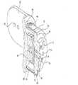
エンドエフェクタ22は、図6に示すように、ロボット支持システム4に手術ツールを接続するために使用されてもよい。エンドエフェクタ22は、サドルジョイント62、作動アセンブリ60、ロードセル64、及びツール接続部66を備えることができる。サドルジョイント62は、エンドエフェクタ22をSCARA24に取り付けることができる。サドルジョイント62は、任意の適切な材料で作ることができる。適切な材料は、チタン、アルミニウム、またはステンレス鋼のような金属、炭素繊維、ガラス繊維、または頑丈なプラスチックであり得るが、これらに限定されない。サドルジョイント62は、エンドエフェクタに追加の強度及び耐久性を提供することができる単一の金属片で作ることができる。実施例では、サドルジョイント62は、取り付け点68によってSCARA24に取り付けることができる。サドルジョイント62の周りに配置された複数の取り付け点68があってもよい。取り付け点68は、サドルジョイント62上に沈められ、揃えられ、及び/または配置され得る。実施例では、ねじ、ナット及びボルト、及び/またはそれらの任意の組み合わせが、取り付け点68を通過して、サドルジョイント62をSCARA24に固定することができる。ナット及びボルトは、サドルジョイント62をSCARA24内の図示しないモータに接続することができる。モータは、サドルジョイント62を任意の方向に動かすことができる。モータはさらに、現場で能動的にサーボ制御することによって、またはばね作動式ブレーキを適用することによって受動的に、サドルジョイント62が偶発的なバンプ及び/または偶然の接触から動くことを防止することができる。サドルジョイント62は、ロードセル64及びツール接続部66が配置される基部を提供することができる。 The
図7及び図8に示すように、ロードセル64は、任意の適切な手段によってサドルジョイント62に取り付けることができる。適切な手段は、ねじ、ナット及びボルト、ねじ込み、圧入継手、ならびに/またはそれらの任意の組合せであり得るが、これらに限定されない。ロードセル64は、移動を検出して測定するために使用される任意の適切な器械であってもよい。実施例では、ロードセル64は、6軸ロードセル、3軸ロードセル、または1軸ロードセルであってもよい。ロードセル64を使用して、エンドエフェクタ22に加えられる力を追跡することができる。図17に示すように、概略図は、ロードセル64とモータ120との間の通信を示す。実施形態では、ロードセル64は、複数のモータ120と通信することができる。ロードセル64が圧力を感知すると、加えられる力の量に関する情報は、スイッチアレイ122及び/または複数のスイッチアレイからマイクロコントローラユニット122に分配され得る。マイクロコントローラユニット124は、ロードセル64から力情報を取得し、それをスイッチアルゴリズムで処理することができる。スイッチアルゴリズムは、マイクロコントローラユニット124がモータドライバ126と通信することを可能にすることができる。モータドライバ126は、モータドライバ126が通信できるモータ120の機能を制御することができる。モータドライバ126は、モータ120を介してロードセル64によって測定された等しい量の力を生成するように、特定のモータ120を誘導することができる。実施形態において、生成される力は、マイクロコントローラユニット124によって指示されるように、複数のモータ120から生じ得る。さらに、モータドライバ126は、モーションコントローラ128からの入力を受け取ることができる。モーションコントローラ128は、ロードセル64によって感知された力の方向に関する情報をロードセル64から受け取ることができる。モーションコントローラ128は、モーションコントローラアルゴリズムを使用してこの情報を処理することができる。このアルゴリズムは、特定のモータドライバ126に情報を提供するために使用することができる。力の方向を複製するために、モーションコントローラ128は、特定のモータドライバ126を作動及び/または停止することができる。一元的に及び/または別々に作業し、マイクロコントローラユニット124及びモーションコントローラ128は、モータ120(または複数のモータ120)を制御して、ロードセル64によって感知される力の運動及び方向を、その方向に誘導することができる。この力制御運動は、操作者がSCARA24及びエンドエフェクタ22を容易に及び/またはほとんど抵抗なく移動させることを可能にする。エンドエフェクタ22の移動は、医療従事者による使用のための任意の適切な位置にツール接続部66を配置することができる。 As shown in FIGS. 7 and 8, the
ツール接続部66は、ロードセル64に取り付けることができる。ツール接続部66は、取り付け点68、感覚ボタン70、ツールガイド72、及び/またはツール接続部74を備えることができる。図6及び図8に示すように、複数の取り付け点68があってもよい。取り付け点68は、ツール接続部66をロードセル64に接続することができる。取り付け点68は、ツール接続部66に沈められ、揃えられ、及び/または配置されてもよい。コネクタ76は、取り付け点68を使用してツール接続部66をロードセル64に取り付けることができる。実施例では、コネクタ76は、ねじ、ナット及びボルト、圧入継手、ならびに/またはそれらの任意の組み合わせであってもよい。 The
図6に示すように、ツール接続部66の中心の周りに感覚ボタン70を配置することができる。感覚ボタン70は、図4に最もよく示されているエンドエフェクタツール26が、エンドエフェクタ22に接続されているときに、押し下げることができる。感覚ボタン70の押下は、エンドエフェクタツール26がエンドエフェクタ22に取り付けられていることを、ロボット支持システム4、さらには医療従事者に警告することができる。図6に示すように、ツールガイド72を使用して、エンドエフェクタツール26のエンドエフェクタ22への適切な取り付けを容易にすることができる。ツールガイド72は、ツール接続部66上に沈められ、揃えられ、及び/または配置され得る。実施例では、複数のツールガイド72があり、任意の適切なパターンを有し、任意の適切な方向に向けることができる。ツールガイド72は、エンドエフェクタツール26のエンドエフェクタ22への取り付けを容易にするための任意の適切な形状とすることができる。適切な形状は、円形、長円形、正方形、多面体、及び/またはそれらの任意の組み合わせであり得るが、これらに限定されない。さらに、ツールガイド72は、面取り、直線、及び/またはそれらの任意の組み合わせで切断することができる。 As shown in FIG. 6, the sensory button 70 can be arranged around the center of the
ツール接続部66は、取り付け点74を有してもよい。図6に示すように、取り付け点74は、棚部及び/または複数の棚部を形成することができる。取り付け点74は、エンドエフェクタツール26に、エンドエフェクタツール26がクランプし得る面を提供することができる。実施例では、取り付け点74は、ツール接続部66の任意の面の周りに配置され、ツール接続部66に対して任意の適切な方法で配向されてもよい。 The
ツール接続部66は、作動アセンブリ60のためのプラットフォームとしてさらに機能することができる。図6及び図8に最もよく示されている作動アセンブリ60は、ツール接続部66を取り囲むことができる。実施形態では、作動アセンブリ60は、ブレスレットの形態をとってもよい。ブレスレットとして、作動アセンブリ60は、ツール接続部66を包んでもよい。実施形態では、作動アセンブリ60は、自動医療システム2内の任意の適切な領域に配置されてもよい。実施例では、作動アセンブリ60は、SCARA24の任意の部分に配置することができ、エンドエフェクタ22の任意の部分は、医療従事者(及び無線で通信する)及び/またはそれらの任意の組み合わせによって装着することができる。作動アセンブリ60は、任意の適切な材料から作製することができる。適切な材料は、ネオプレン、プラスチック、ラガー、ゲル、炭素繊維、布地及び/またはそれらの任意の組み合わせであり得るが、これらに限定されない。作動アセンブリ60は、一次ボタン78及び二次ボタン80を備えることができる。一次ボタン78及び二次ボタン80は、ツール接続部66の全体を囲むことができる。図6に示すように、一次ボタン78は、ツール接続部66を囲むことができる単一の隆起部であってもよい。例では、サドルジョイント62から最も離れた端部に沿って作動アセンブリ60の上に一次ボタン78を配置することができる。一次ボタン78は、図7に最もよく示されている、一次作動スイッチ82の上に配置されてもよい。一次作動スイッチ82は、ツール接続部66と作動アセンブリ60との間に配置されてもよい。実施例では、一次ボタン78の全長に沿って一次ボタン78の下に隣接して配置することができる複数の一次作動スイッチ82があってもよい。一次作動スイッチ82上の一次ボタン78を押し下げることにより、操作者はSCARA24及びエンドエフェクタ22を移動させることができる。上述したように、一旦所定位置に設定されると、SCARA24及びエンドエフェクタ22は、操作者がSCARA24及びエンドエフェクタ22を動かすためにロボット支持システム4をプログラムするか、または一次ボタン78及び一次作動スイッチ82を使用して移動するまで動くことができない。実施例では、SCARA24及びエンドエフェクタ22がコマンドに応答する前に、少なくとも2つの隣接していない一次作動スイッチ82の押下を必要とすることがある。少なくとも2つの一次作動スイッチ82の押下は、医療処置中のSCARA24及びエンドエフェクタ22の偶発的な移動を防ぐことができる。 The
一次ボタン78及び一次作動スイッチ82によって作動されると、ロードセル64は、力の大きさ、及び/または医療従事者によってエンドエフェクタ22に及ぼされる力の方向を測定することができる。この情報は、SCARA24及びエンドエフェクタ22を動かすために使用され得るSCARA24内のモータに転送され得る。ロードセル64によって測定された力の大きさ及び方向に関する情報は、モータが、ロードセル64によって感知されるのと同じ方向にSCARA24及びエンドエフェクタ22を移動させ得る。この力制御された動きは、操作者がSCARA24及びエンドエフェクタ22を動かすと同時に、モータがSCARA24及びエンドエフェクタ22を動かすことにより、SCARA24及びエンドエフェクタ22を容易にかつ大量の労力なしに動かすことを可能にする。 When activated by the
図6に示すように、二次ボタン80は、サドルジョイント62に最も近い作動アセンブリ60の端部に配置することができる。実施例では、二次ボタン80は、複数の隆起部を備えてもよい。複数の隆起部は、互いに隣接して配置されてもよく、ツール接続部66を取り囲んでもよい。さらに、二次作動スイッチ84の上に二次ボタン80を配置することができる。図7に示すように、二次作動スイッチ84は、二次ボタン80とツール接続部66との間に配置することができる。実施例では、二次ボタン80は、「選択」装置として操作者によって使用されてもよい。医療操作中、ロボット支持システム4は、ディスプレイ34及び/または光インジケータ28によって医療従事者に特定の状態を通知することができる。医療従事者は、機能、モードを選択するためにロボット支持システム4によって促され、及び/または自動医療システム2の状態を検査することができる。二次作動スイッチ84上の二次ボタン80を一回押し下げすると、ディスプレイ34及び/または光インジケータ28を介して医療従事者に伝達される特定の機能、モード、及び/または確認情報を起動することができる。さらに、二次作動スイッチ84上の二次ボタン80が急速に連続して複数回押し下げられると、ディスプレイ34及び/または光インジケータ28を介して医療従事者に伝達される追加の機能、モード、及び/または選択情報を起動できる。実施例では、二次ボタン80が適切に機能する前に、少なくとも2つの隣接しない二次ボタン作動スイッチ84を押し下げることができる。この必要条件は、二次ボタン80が意図せず使用されて、作動アセンブリ60の医療関係者による偶発的な衝突を防止することができる。一次ボタン78及び二次ボタン80は、医療従事者のコマンドを自動医療システム2に通信するためにソフトウェアアーキテクチャ86を使用することができる。 As shown in FIG. 6, the
図9は、自動医療システム2内で使用され得るソフトウェアアーキテクチャ86のフローチャートを示す。ソフトウェアアーキテクチャ86は、自動ロボット支持システム4及びカメラ追跡システム6に使用されてもよい。さらに、ソフトウェアアーキテクチャ86は、操作者が操作者から与えられたコマンドに基づいて自動医療システム2を操作することを可能にすることができる。実施例では、操作者コマンドは、PACS(Picture Archival and Communication Systems)88(以下に説明する自動イメージングシステム104と通信することができる)、USB装置90、及びタブレット54からのコマンドを備えることができる。これらの操作者コマンドは、コンピュータプロセッサ92によって自動医療システム2を通して受信され、転送されてもよい。コンピュータプロセッサ92は、全てのコマンドを受信し、それに応じて自動医療システム2を操作することができる。実施例では、コンピュータプロセッサ92は、自動医療システム2を備える個々の部品の位置を制御及び識別することができる。カメラ追跡システム6及びディスプレイ34と通信することにより、コンピュータプロセッサ92は、患者、エンドエフェクタ22、及びロボット支持システム4を所定の空間(例えば、図5に示す)に配置することができる。さらに、コンピュータプロセッサ92は、ディスプレイ34及びカメラ追跡システム6からのコマンドを使用して、SCARA24の位置を変更することができる。測定された力の大きさ及び方向に基づいて、ロードセル64からの情報は、コンピュータプロセッサ92によって処理され、上述したようにSACARA24内のモータに送られる。一般代数モデリングシステム(GAMS)94は、ロードセル64からの力の大きさに関する情報を、コンピュータプロセッサ92によって使用可能な電子信号に変換することができる。この変換によって、コンピュータプロセッサ92は、SCARA24及びエンドエフェクタ22が動いているときの定義された空間内のロボット支持システム4の位置及び動きを追跡することができる。コンピュータプロセッサ92はさらに、ファームウェア96を使用して、ロボット本体8からのコマンド及び信号を制御することができる。ファームウェア96は、自動医療システム2に配線されたコマンドを備えることができる。例えば、コンピュータプロセッサ92は、動作するために電源98からの電力を必要とすることがある。ファームウェア96は、電源98から自動医療システム2への電力の分配を制御することができる。さらに、コンピュータプロセッサ92は、操作者コマンドに基づいてファームウェア96及び電力分配を制御することができる。実施例では、ファームウェア96は、光インジケータ28、電動車輪12、及びプラットフォームインタフェース100と通信することができる。プラットフォームインタフェース100は、自動医療システム2を直接制御する一連のハードワイヤードボタンコマンドであってもよい。ボタンコマンドは、限定はされないが、自動医療システム2を任意の方向に動かし、緊急停止を開始し、SCARA24の動きを開始し、及び/または現在のシステム機能を医療従事者に伝える機能を備えていてもよい。コンピュータプロセッサ92は、医療従事者によるプログラムされたタスクを実行するために、全ての操作者コマンドを処理し分配することができる。 FIG. 9 shows a flowchart of software architecture 86 that can be used within the automated
自動イメージングシステム104は、患者50の術前、手術中、術後、及び/またはリアルタイムの画像データを取得するために、自動医療システム2と併せて使用されてもよい。任意の適切な主題は、自動イメージングシステム104を用いて任意の適切な手順のためにイメージング化することができる。実施形態では、自動イメージングシステム104は、イメージング装置106及び/またはCアーム108装置などの任意のイメージング装置であってもよい。X線システムで必要とされる患者50を頻繁に手動で再位置決めする必要なしに、多数の異なる位置から患者50のX線を取得することが望ましい場合がある。Cアーム108のX線診断装置は、頻繁な手動再位置決めの問題を解決することができ、手術及び他の介入処置の医療技術において周知である。図10に示すように、Cアーム108は、「C」字形の対向する遠位端112で終端する細長いC字形部材110を備えることができる。C字形部材110は、それぞれ、反対方向のCアーム108の遠位端112に、またはその近くに、Cアーム108が懸架位置に支持された状態で取り付けられ得る、X線源114及び画像受容器116をさらに備えることができる。アームのCアーム108内の空間は、医師がX線支持構造118からの干渉が実質的にない患者に付き添うための余地を提供することができる。X線支持構造118は車輪120に載ることができ、医療処置中にCアーム108を部屋から部屋に、さらに患者50の長さに沿って回転させることができる。Cアーム108から生成されたX線画像は、自動医療システム2が医療処置中に適切に配置されることを確実にするのに役立つように、手術室環境で使用されてもよい。 The
Cアーム108は、アームの2つの自由度(すなわち、球面運動における2つの垂直軸の周り)の回転運動を可能にするように取り付けられてもよい。Cアーム108は、その曲率の中心についてCアーム108の回転運動を公転させることができ、X線源114及び画像受容器116の垂直方向及び/または水平方向の選択的な配向を可能にし得る、X線支持構造118に摺動可能に取り付けられてもよい。Cアーム108は、横方向に回転可能であってもよく、(すなわち、患者50の幅及び長さの両方に対するX線源114及び画像受容器116の選択的調整可能な位置決めを可能にするために、旋回方向に対して垂直な方向に)。Cアーム108装置の球面的な回転態様により、医師は、イメージング化される特定の解剖学的状態に関して決定される最適な角度で患者50のX線を撮影することができる。実施形態では、Cアーム108は、車輪付き支持カート120に支持されてもよい。実施形態では、イメージング装置106は、Cアーム108と別々に、及び/またはCアーム108と共に使用されてもよい。 The C-
図11に示すように、イメージング装置106は、図示されていない画像取得部を囲むことができるガントリハウジング124を含み得る。画像取得部は、互いに約180度に配置され、画像取得部の追跡と関連してロータ(図示せず)に取り付けられ得る、X線源及び/または放出部と、X線受信及び/または画像受信部とを含み得る。画像取得部は、画像取得中に360度回転するように動作可能であってもよい。画像取得部は、中心点及び/または軸の周りを回転し得、患者50の画像データが複数の方向または複数の平面から取得されることを可能にする。 As shown in FIG. 11, the imaging apparatus 106 may include a
実施形態では、イメージング装置106は、イメージング化対象の周りに位置決めするための中心開口126を有するガントリハウジング124と、ガントリハウジング124の内部周りで回転可能な放射線源とを備え、複数の異なる投影角度から放射線を投影するように適合されてもよい。検出器システムは、複数の投影面から対象画像を擬似的に取得するために、各投影角度で放射線を検出するように適合されてもよい。いくつかの実施形態では、ガントリは、車輪132を有する車輪付き移動式カート130のような支持構造イメージング装置支持構造128に片持ち式で取り付けられてもよい。位置決めユニット134は、好ましくはコンピュータ化された動作制御システムの制御下で、ガントリを所望の位置及び配向に並進及び/または傾斜させることができる。ガントリは、ガントリ上に互いに対向して配置された電源及び検出器を含むことができる。電源及び検出器は、互いに協調してガントリの内部周りで源及び検出器を回転させることができる電動ロータに固定されてもよい。電源は、ガントリ内部に位置する標的物体の多平面イメージングのために、部分的及び/または完全な360度の回転にわたって複数の位置及び配向でパルスされてもよい。ガントリは、ロータが回転するときにロータを案内するためのレール及び軸受システムをさらに備え、ロータは、電源及び検出器を担持することができる。イメージング装置106及びCアーム108の両方及び/またはいずれかを自動イメージングシステム104として使用して患者50をスキャンし、情報を自動医療システム2に送信することができる。 In an embodiment, the imaging apparatus 106 comprises a
自動イメージングシステム104は、イメージングが行われる前、その間、及び/または後に、自動医療システム2と通信することができる。通信は、ハードワイヤ接続及び/またはワイヤレス接続を介して実行されてもよい。イメージングが生成され、リアルタイムで自動医療システム2に送ることができる。自動イメージングシステム104によって捕捉された画像は、ディスプレイ34に表示することができ、これにより医療従事者は患者内の骨及び器官の位置を特定することができる。これにより、医療従事者は、自動医療システム2を医療操作中に支援するようにプログラムすることができる。 The
医療操作中、医療従事者は、ロボット支持システム4を定義された仕様内で動作させるようにプログラムすることができる。例えば、図12に示すように、患者50は、脊椎に対して行われる医療処置を有することができる。医療従事者は、上記したように、画像機器を使用して脊椎を見つけ、位置を特定することができる。画像を用いて、操作者は、脊柱の位置に関する情報を自動医療システム2にアップロードすることができる。次いで、自動医療システム2は、エンドエフェクタツール26を追跡し、位置決めし、操作者によって指定された領域に移動させることができる。一実施例では、重力ウェル102及び/または複数の重力ウェル102は、図12に示すように、患者50の脊椎にマッピングすることができる。重力ウェル102は、エンドエフェクタツール26を引き付けるために、操作者によってプログラムされた領域であってもよい。これらの領域は、SCARA24及びエンドエフェクタ22を医療従事者によってプログラムされた方向、角度、及び位置に向かって動かすことができる。 During medical operation, the healthcare professional can program the robot support system 4 to operate within defined specifications. For example, as shown in FIG. 12,
図13に示すように、重力ウェル102は、仮想空間において角度及び位置エンドエフェクタツール26が医療処置のために配置される必要があることを示す。図示されているように、エンドエフェクタツール26は、上述した作動アセンブリ60を使用して操作者によって移動させることができる。エンドエフェクタツール26が重力ウェル102の領域内を移動すると、操作者はSCARA24内のモータがエンドエフェクタツール26を重力ウェル102のプログラムされた位置に移動させることを感じ得る。図14に示すように、重力ウェル102は、エンドエフェクタツール26をプログラムされた位置に移動させることができる。一実施例では、操作者が起動アセンブリ60を使用してエンドエフェクタツール26を移動させ始めると、操作者はモータがその動きに対して抵抗を提供すると感じ得る。モータからの抵抗は、エンドエフェクタツール26を重力ウェル102内に保持するのに十分な抵抗力ではない。これは、操作者がエンドエフェクタツール26を追加の重力ウェル102に操作することを可能にするので有益であり得る。重力ウェル102は、医療操作の前及び/または医療操作中に、自動医療システム2にプログラムされてもよい。これにより、医療従事者は、医療処置の変化する条件に基づいて重力ウェル102を移動させることができる。重力ウェル102は、自動医療システム2がエンドエフェクタツール26を必要な領域に迅速かつ容易に正確に配置することを可能にする。 As shown in FIG. 13, the gravity well 102 indicates that the angle and position
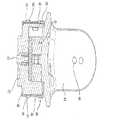
図15は、中空管202を画定するツール部分26を含むロボットのエンドエフェクタ22の一部を示す。ロボット支援手術では、金属手術器械204のような金属物体が中空管202内に挿入される。中空管202は、金属手術器械204の少なくとも一部を受け入れるようにサイズ決めされ及び構成されている。金属物体は、ガイドワイヤ、カニューレ、リトラクター、ドリル、リーマ、ドライバ、挿入ツール、除去ツールなどを含むが、これらに限定されない、当技術分野で知られている任意の適切な手術器械204を含むことができる。中空管202は一般に円筒の構成を有するものとして示されているが、中空管202は、手術器械204を収容し、手術部位にアクセスするのに望ましい任意の適切な形状、サイズ、及び構成を有し得ることが当業者には理解されよう。 FIG. 15 shows a portion of a
手術処置が行われる前に、中空管202は、手術器械204の挿入及び/または軌道が患者の上または体内の所望の解剖学的標的に到達できるように、ロボットアーム20によって整列及び/または配向されるように構成される。したがって、手術器械204は、ロボット4を操作した後に中空管202内に挿入され、所望の手術処置のためのこの所望の整列及び/または配向を達成することができる。好ましくは、金属手術器械204が中空管202の一部を通って挿入されるか、中空管202全体を通って挿入されると、ロボットシステムはシャットダウンされることが好ましい。したがって、金属手術器械204が管202内に挿入されたとき、器械204の存在及び/または器械204の挿入は、安全上の理由から、カメラ、赤外線検出器などのロボット4の1つ以上の電子部品を遮断するために検出されるべきである。この安全機構は、金属手術器械204がエンドエフェクタ22内に存在するとき、ロボット4、特にロボットアーム20、特にエンドエフェクタ22が動かないことを確実にする。したがって、この自動遮断システムは、管202を通って位置決めされた手術器械204の軌道及び向きが操作中に変化しないので、患者の安全を確保する。 Prior to the surgical procedure, the hollow tube 202 is aligned and / or by the
管202内に金属手術器械204が存在することを検出するために、センサを使用することができる。例えば、センサは、インダクタコイル206の形態であってもよい。図15に示すように、インダクタコイル206が中空管204の周囲に配置される。インダクタコイル206は、管204の内側または外側のいずれかに配置することができる。加えて、誘導コイル206は、管202の長さに沿った適切な位置に配置することができる。例えば、コイル206は、実質的に管202の長手方向中心に配置されてもよい。コイル206は、管202の長さに沿った他の位置、例えば、遠位端または近位端に近接して配置されてもよいことが理解されよう。 A sensor can be used to detect the presence of the metal surgical instrument 204 in the tube 202. For example, the sensor may be in the form of an inductor coil 206. As shown in FIG. 15, the inductor coil 206 is arranged around the hollow tube 204. The inductor coil 206 can be located either inside or outside the tube 204. In addition, the induction coil 206 can be placed at an appropriate position along the length of the tube 202. For example, the coil 206 may be substantially centered in the longitudinal direction of the tube 202. It will be appreciated that the coil 206 may be placed in other positions along the length of the tube 202, eg, in close proximity to the distal or proximal end.
図16は、本発明の態様による減衰波形生成器208の概略図である。インダクタ206と並列に接続されたコンデンサ210は、発電機208の共振回路を形成する。電圧源Vsは、スイッチSW1と直列に接続された電流制限抵抗R1を介して共振回路に電流を供給する。二次抵抗R2は、共振回路と出力端子Voutとの間に接続されている。 FIG. 16 is a schematic view of an attenuation waveform generator 208 according to an aspect of the present invention. The
第1のクランプダイオードD1は、アノードが接地に接続され、カソードが出力端子Voutに接続されている。第2のクランプダイオードD2は、アノードが出力端子Voutに接続され、カソードが基準電圧源Vcmpに接続されている。スイッチSW1は、図17に示すようにコントローラ240の制御下にある。 In the first clamp diode D1, the anode is connected to the ground and the cathode is connected to the output terminal Vout. In the second clamp diode D2, the anode is connected to the output terminal Vout and the cathode is connected to the reference voltage source Vcmp. The switch SW1 is under the control of the
簡潔には、操作中、コントローラ240がスイッチSW1を所定時間間隔τの間オンにすると、スイッチSW1は電圧源Vsを共振回路(206、210)に接続し、電圧源Vsからの電流をコイル206に流し、コンデンサ210の両端に初期電圧Vcを印加する。この動作は、インダクタLの初期チャージを値(Vs・τ)に設定し、ここで、τはスイッチオン時間である。 Briefly, during operation, when the
コントローラ240がスイッチSW1をオフにすると、電圧源Vsは共振回路(206、210)から切断され、コンデンサ210の両端の電圧は減衰的に振動し始める。抵抗R2は、出力端子Voに供給される電流を設定する。クランプダイオードD1は、出力端子Voutにおける電圧が実質的に接地より下に落ちないように確実にする。コンデンサ210が出力電圧をゼロより下に引っ張ろうとすると、ダイオードD1がオンになり、例えば出力端子Voutの最小電圧が−0.3ボルトとなるように、出力端子Voutをダイオードの順方向バイアス電圧(例えば、0.3V)よりも低い接地電圧に強制する。事実上、クランプダイオードD1は整流器として作用し、出力端子Voutに正の電圧のみを供給する。 When the
一方、出力端子Voutの電圧が基準電圧Vcmpを超えようとすると、クランプダイオードD2がオンになり、出力電圧をVcmpプラスダイオードの順方向バイアス電圧(例えば、0.3V)にクランプする。基準電圧Vcmpは、コントローラ240に対して許容される最大電圧(例えば、5V)に設定され、波形生成器208を市場にある任意の数のマイクロコントローラユニットに適合させることができる。したがって、出力端子Voutの最大電圧は5.3ボルトである。 On the other hand, when the voltage of the output terminal Vout tries to exceed the reference voltage Vcmp, the clamp diode D2 is turned on and the output voltage is clamped to the forward bias voltage (for example, 0.3V) of the Vcmp plus diode. The reference voltage Vcmp is set to the maximum voltage allowed for the controller 240 (eg, 5V) and the waveform generator 208 can be adapted to any number of microcontroller units on the market. Therefore, the maximum voltage of the output terminal Vout is 5.3 volts.
コントローラ240がスイッチSW1をオフにしない場合、例えばコントローラ240がフリーズした場合、電流制限抵抗R1(例えば330オーム)が、コイル206が損傷しないことを確実にする。 If the
スイッチSW1がオフにされた直後に、出力端子Voutにおいて結果として生じる減衰波形がコントローラ240に記憶される。次いで、記憶された減衰波形を解析して、共振回路の実効Q値を決定することができる。本構成では、回路のQ値は Immediately after the switch SW1 is turned off, the resulting attenuation waveform at the output terminal Vout is stored in the

であり、式中、ESRはコイル「実効直列抵抗」である。Q値は、コイルのインダクタンス及びそのESRの両方に応じて変化する可能性があり、波形の減衰の変化に関与するのはこのQの変化である。有効なQ値を使用して、中空管202内の金属物体204の存在及び挿入の深さを決定し、例えば、以下でより詳細に説明されるように、金属物体が完全に挿入されたかどうかを決定することができる。In the equation, ESR is the coil "effective series resistance". The Q value can change depending on both the inductance of the coil and its ESR, and it is this change in Q that contributes to the change in waveform attenuation. A valid Q value was used to determine the presence and insertion depth of the metal object 204 in the hollow tube 202, eg, was the metal object fully inserted, as described in more detail below. You can decide whether or not.
図17は、本発明の一態様による管202内の金属物体204の存在または挿入を検出するためのコントローラ240の概略図である。 FIG. 17 is a schematic diagram of a
本発明のコントローラ240は、通信リンク252から情報を受信し、通信リンク252を介して情報を送信する、I/Oインタフェース242に接続された通信リンク252を介して出力端子Vout及びスイッチSW1に接続される。コントローラ240は、RAM(ランダムアクセスメモリ)などのメモリ記憶装置244、プロセッサ(CPU)246、FPGA、ROM、またはEEPROMなどのプログラム記憶装置248、及びハードディスクなどのデータ記憶装置250などを含み、全てが共通にバス253を介して互いに接続されている。プログラム記憶装置248は、とりわけ、プロセッサ246によって実行されるソフトウェアを含む金属検出モジュール254を記憶する。 The
プロセッサ246によって実行される金属検出モジュール254は、スイッチSW1を制御する。モジュール254は、減衰波形の周波数を制御するために可変インダクタまたはコンデンサが使用された場合に、インダクタ206及びコンデンサ210を制御することもできる。 The metal detection module 254 executed by the
金属検出モジュール254は、ディスプレイ装置211を介してユーザと対話するユーザインタフェースモジュールと、キーボード212などの入力装置と、矢印キー、マウス、またはトラックボールなどのポインティング装置214とを含む。ユーザインタフェースモジュールは、波形生成器208内のプログラム可能な構成要素をプログラムし、本明細書でより詳細に説明するデータの較正を行う際にユーザを支援する。プログラム記憶装置248内のソフトウェアプログラムモジュール及びデータ記憶装置250からのデータのいずれも、必要に応じてメモリ244に転送され、CPU246によって実行される。 The metal detection module 254 includes a user interface module that interacts with the user via the
アナログ−デジタル(A/D)変換器243が、I/Oインタフェース242に接続されている。A/D変換器243は、出力端子Voutのアナログ減衰波形をデジタルデータに変換し、プロセッサ246により記憶装置250に記憶する。 An analog-to-digital (A / D) converter 243 is connected to the I /
1つの例示的なコントローラ240は、Santa Clara,CAのIntel Corporationの8051マイクロコントローラであってもよい。しかし、A/D変換器を提供する任意のプロセッサまたはマイクロコントローラを使用することができる。 One
一実施形態では、入力装置212、214、及びディスプレイ装置211を含むコントローラ240の一部または全部を、図1の自動医療システム2に組み込むことができる。例えば、ディスプレイ211は、ディスプレイ34と同じであってもよい。 In one embodiment, some or all of the
次に、金属検出モジュール254による(例えば、手術器械204の)金属検出及び/または深さ決定を行う方法を、図21を参照して説明する。ステップ256において、金属検出モジュール254のユーザインタフェースは、データ記憶装置250に記憶されたスイッチオン時間τ、金属検出計算方法、及び較正モードを選択する際にユーザと対話する。ユーザまたはモジュール254自体が較正モードを選択した場合、その後、すべてのステップが使用され、中空管202内の金属物体204の存在及び深さを決定する際に後で使用するために、記憶装置250に記憶するためのいずれの金属物体も伴わないで初期Q値(及び初期インダクタンス値)を決定する。 Next, a method of performing metal detection and / or depth determination by the metal detection module 254 (eg, surgical instrument 204) will be described with reference to FIG. In
ステップ258において、コントローラ240は、リンク252を介して予め選択された時間(例えば、100マイクロ秒)の間スイッチSW1をオンにする信号を送る。スイッチSW1は、電圧源Vsを共振回路(6、10)に接続し、電流IeがR1を流れる。これにより、コンデンサ210の両端に初期電圧Vsが印加され、コイル206は(Vs・τ)の初期磁束レベルにプリチャージされる。次いで、この磁気電荷は、スイッチSW1がオフになるまで、コイル206に蓄積される。スイッチSW1がオフになると、共振回路の共振電流は減衰波形を出力する。In
ステップ260において、出力端子Voutにおける減衰波形はデジタルデータに変換され、記憶装置250に記憶される。 In
ステップ262において、インダクタ206のQ値は、以下の方法により算出される。 In step 262, the Q value of the inductor 206 is calculated by the following method.
コイル206の初期電流は、2つの異なる方法によって設定することができる。第1の方法は、十分長い時間スイッチSW1を閉じたままにし、Ieをv/(R1+ESR)に安定させることである。The initial current of coil 206 can be set by two different methods. The first method is to keep the switch SW1 closed for a sufficiently long timeto stabilize Ie to v / (R1 + ESR).
他の方法は、初期電流をv/L・τに設定する「短時間」τの間スイッチSW1をオンに維持することであり、式中、Lはコイル206のインダクタンスである。 Another method is to keep the switch SW1 on for a "short time" τ that sets the initial current to v / L · τ, where L is the inductance of the coil 206.
このような初期電流がコイル206に確立され、コンデンサ210の両端間の初期電圧の後、SW1が開き、回路はコンデンサ210における減衰電圧波形としてそれ自体の固有周波数で共振することが可能になる。コンデンサ210の両端の電圧は、コイル206のQ値が何であるかを計算するためにモニタされてもよい。コンデンサ両端の時間領域電圧(V_c (t))とコイルのインダクタンスLとの関係は、方程式1で実現される。 Such an initial current is established in the coil 206, and after the initial voltage between both ends of the
式中、 During the ceremony
v=電源電圧Vs、
ω0=コイル206及びコンデンサ210の自然な非減衰共鳴周波数、
γ=コイルのESR(実効直列抵抗)を含むコイル206及びコンデンサ210の減衰係数、
τ=スイッチSW1のオン時間、そして
ωn=固有共振周波数。
上で定義したγはESRとコイルのインダクタンスLの両方を含んでおり、したがってQ値に直接関係していることに留意されたい。その関係は次のとおりである。v = power supply voltage Vs,
ω0 = natural non-attenuation resonance frequency of coil 206 and
γ = Attenuation coefficient of coil 206 and
τ = switch SW1 on time, and ωn = natural resonance frequency.
Note that the γ defined above contains both the ESR and the coil inductance L and is therefore directly related to the Q value. The relationship is as follows.
コンデンサ210の両端の電圧はR2に電流を生成し、出力端子Voutで生成される典型的な波形は図18に示される。t=0では、スイッチSW1がオフになる。図18に示すように、波形の最初の3波(t2〜t4、t5〜t7、及びt8〜t10)のみが示されている。波形は、t=t3に第1のピーク電圧を、t=t6に第2のピークを、t=t9に第3のピークを有する。 The voltage across the
減衰波形は、コイル206のQ値が何であるかを計算するために多くの方法で使用することができる。Q値を決定する第1の方法は、波形の「平均値」を測定することである。平均値は、波形の下の面積の積分を所定の波数または時間周期にわたって計算し、次に電圧が存在する時間間隔で除算することによって実現することができる。平均値とQ値との間の関係は、経験的にまたは方程式(1)によって決定することができる。 The decay waveform can be used in many ways to calculate what the Q value of coil 206 is. The first method of determining the Q value is to measure the "average value" of the waveform. The mean value can be achieved by calculating the integral of the area under the waveform over a given wavenumber or time period and then dividing by the time interval in which the voltage is present. The relationship between the mean and the Q value can be determined empirically or by equation (1).
Q値を決定する別の方法は、ピーク電圧Vout1、Vout2及びVout3及びそれらの対応する時間t3、t6及びt9のうちの1つ以上を測定することである。例えば、第1のピークにおける電圧値(すなわち、図17のVout1)及びt=t3を決定することができる。これらの値から、方程式(1)からQ値を計算することができる。 Another method of determining the Q value is to measure one or more of the peak voltages Vout1, Vout2 and Vout3 and their corresponding times t3, t6 and t9. For example, the voltage value at the first peak (ie, Vout1 in FIG. 17) and t = t3 can be determined. From these values, the Q value can be calculated from the equation (1).
Q値を決定するもう1つの方法は、時間t2、t4、t5、t7、t8、及びt10で生成するゼロ交差電圧を測定することである。これらの値から、方程式(1)からQ値を計算することができる。 Another way to determine the Q value is to measure the zero crossover voltage generated at time t2, t4, t5, t7, t8, and t10. From these values, the Q value can be calculated from the equation (1).
Q値を決定するさらに別の方法は、tn>3τのように(τが共振回路の時定数である)、時間t0〜tnにおける波形の積分を計算することによって、時間「窓」にわたって波形の信号エネルギーを測定することである。これらの値から、方程式(1)からQ値を計算することができる。Yet another method of determining the Q value, as tn> 3τ (τ is the time constant of the resonant circuit), by calculating the integral of the waveform at time t0 ~tn, the time "window" It is to measure the signal energy of the waveform over. From these values, the Q value can be calculated from the equation (1).
これらのうち、1つの例示的な実施形態は、時間窓にわたる第4の統合方法を使用する。波形信号は、ある時間tにわたってA/D変換器243によってサンプリングされるので、コントローラ240の金属検出モジュール254は、信号を積分する方法としてサンプリングされた信号の和を計算することができる。その合計は、上記の方程式(1)または経験的によって異なるQの値と比較または特徴づけることができる。この特徴付けは、探索表として記憶装置に格納することができ、この探索表は、金属検出モジュール254によって補間によって検索され使用されることができる。 Of these, one exemplary embodiment uses a fourth integration method over a time window. Since the waveform signal is sampled by the A / D converter 243 over a period of time t, the metal detection module 254 of the
ステップ264において、金属検出モジュール254は、金属物体204が中空管202内に存在するか否かを判定する。一実施例として、一実施形態では、ステップ256において、ユーザが第1のピーク電圧決定を、Q値を得る方法として選択したと仮定する。Q値が第1のピーク電圧値及びt3値から得られると、金属検出モジュール254は、それを予め選択された閾値と比較する。 In step 264, the metal detection module 254 determines if the metal object 204 is present in the hollow tube 202. As an embodiment, in one embodiment, it is assumed that in
場合によっては、ESRはそれほど変化しない。この場合、Q値は純粋にインダクタンスのみの関数である。図20は、一度t=0における初期電圧が接地に落ちる、計算されたインダクタンス値対第1のピーク値の電圧値(すなわち、図17のt=t3におけるVout1)のグラフを示す。このグラフに基づいて、閾値インダクタンス値は、金属検出モジュール254が、金属物体が存在するとみなす(例えば、金属物体が管202内に実質的に完全に挿入されている)50μHに設定することができる。あるいは、図20のグラフは、Q値対第1のピーク電圧のグラフに変換することができ、L=50μHに相当するQ値の閾値を閾値Q値として記憶することができる。 In some cases, the ESR does not change much. In this case, the Q value is purely a function of inductance only. FIG. 20 shows a graph of the calculated inductance value vs. the voltage value of the first peak value (that is, Vout1 at t = t3 in FIG. 17) once the initial voltage at t = 0 drops to ground. Based on this graph, the threshold inductance value can be set to 50 μH, where the metal detection module 254 considers a metal object to be present (eg, the metal object is substantially completely inserted into the tube 202). .. Alternatively, the graph of FIG. 20 can be converted into a graph of Q value vs. first peak voltage, and the threshold value of Q value corresponding to L = 50 μH can be stored as the threshold Q value.
存在を検出する別の方法は、モジュール254が、金属物体204が中空管202内に存在すると決定する閾値Q値(またはインダクタンス値)を経験的に得ることである。これは、金属物体204をユーザが選択した深さで中空管202に挿入し、減衰波形に基づいてQ値(またはインダクタンス値)を決定することによって行うことができる。 Another way to detect the presence is for the module 254 to empirically obtain a threshold Q value (or inductance value) that determines that the metal object 204 is present in the hollow tube 202. This can be done by inserting the metal object 204 into the hollow tube 202 at a depth selected by the user and determining the Q value (or inductance value) based on the damping waveform.
ステップ266において、金属検出モジュール254は、金属物体204が中空管202内にどれだけ深くあるかを決定する。深さを決定する1つの方法は、所与の金属物体204について様々な深さでQ値(またはインダクタンス値)の探索表を経験的に得ることである。 In step 266, the metal detection module 254 determines how deep the metal object 204 is in the hollow tube 202. One way to determine the depth is to empirically obtain a Q value (or inductance value) search table at various depths for a given metal object 204.
図19は、中空管202への金属物体204の挿入の深さを表す波形生成器208からのいくつかの減衰波形を示す。波形270は、金属物体が存在しない波形を表す。波形270は、いずれの金属物体挿入も伴わないQ1の元のQ値に等しい。波形272は、金属物体204が途中まで挿入された、すなわち金属物体204の遠位端が管202の中心と管の近位端の中間点にあるものを表す。波形72はQ1より小さいQ2のQ値に等しい。波形274は、金属物体204が完全に挿入された、すなわち金属物体204の遠位端がコイル206の中心にあるものを表す。波形274はQ2より小さいQ3のQ値に等しい。したがって、金属物体204の挿入深さは、Q値と負の相関がある。 FIG. 19 shows some decay waveforms from the waveform generator 208 that represent the depth of insertion of the metal object 204 into the hollow tube 202.
このような経験的データに基づいて、探索表を作成することができる。表は、様々なQ値をそれぞれの距離Δx(すなわち、深さ)と等しくする。表が得られると、それは記憶装置250に記憶され、ステップ262からのQ値に基づいて金属物体204の挿入深さを得るために金属検出モジュール254によって使用される。 A search table can be created based on such empirical data. The table equalizes the various Q values to their respective distances Δx (ie, depth). Once the table is obtained, it is stored in storage 250 and used by the metal detection module 254 to obtain the insertion depth of the metal object 204 based on the Q value from step 262.
探索表の別の例を図22に示す。図22は、中空管への金属物体の挿入の深さ(距離Δx)の関数としてのQ値のグラフを示す。この実験は、直径6mmのフェライト金属物体(円筒)及び直径15mm×長さ8mmのコイルで行った。距離Δxは、金属円筒の遠位端からコイルの中心までの距離を表す。図から分かるように、金属円筒204が中空管202内に挿入されると、Q値が変化する。図22のグラフは、金属検出モジュール254による検索のための探索表として記憶装置250に記憶される。探索表が方程式ではなく離散点のセットとして記憶される場合、補間を使用する必要がある。 Another example of the search table is shown in FIG. FIG. 22 shows a graph of the Q value as a function of the insertion depth (distance Δx) of the metal object into the hollow tube. This experiment was carried out with a ferrite metal object (cylinder) having a diameter of 6 mm and a coil having a diameter of 15 mm and a length of 8 mm. The distance Δx represents the distance from the distal end of the metal cylinder to the center of the coil. As can be seen from the figure, when the metal cylinder 204 is inserted into the hollow tube 202, the Q value changes. The graph of FIG. 22 is stored in the storage device 250 as a search table for searching by the metal detection module 254. If the search table is stored as a set of discrete points rather than an equation, then interpolation should be used.
ステップ266において、金属検出モジュール254は、ステップ262で見つかった所与のQ値について、記憶装置250に記憶された探索表から深さ値を探索する。探索表からの深さ値は、金属検出モジュール254からの出力として生成される。 In step 266, the metal detection module 254 searches the depth value from the search table stored in the storage device 250 for the given Q value found in step 262. The depth value from the search table is generated as an output from the metal detection module 254.
図示の実施形態では、波形上で積分するのが比較的簡単であるために、整流された減衰波形が使用されている。完全な整流されていない減衰波形が使用されると、波形の対称性のために単純な積分方法が機能しないため、より多くの構成要素が必要になる。 In the illustrated embodiment, a rectified decay waveform is used because it is relatively easy to integrate on the waveform. When a fully unrectified decay waveform is used, more components are needed because the simple integration method does not work due to the symmetry of the waveform.
本発明は、管202の中心に配置されたコイルを用いて上述したが、近位端、遠位端、または管に沿った任意の位置にコイルを配置することが可能である。また、離間した複数のコイルを使用することも可能である。例えば、互いに均一に離間している3つのコイル(近位端、中心、及び遠位端にそれぞれ配置されている)を使用して、中空管202内の金属物体の存在及び深さを検出することができる。理解され得るように、この実施形態は、中空管202内の金属物体(例えば、手術器械204)の深さを決定するときに特に有用であり得る。複数のコイルが使用される場合、1つの共振回路が別の共振回路に干渉しないように、各インダクタコイルに対してスイッチSW1のオン時間を別々にすることが好ましい(例えば、共振回路をオン及びオフにし、次の共振回路をオンにする前にインダクタンス値を測定する)。 Although the present invention has been described above with a coil located in the center of the tube 202, it is possible to place the coil at the proximal end, the distal end, or at any position along the tube. It is also possible to use a plurality of separated coils. For example, three coils (located at the proximal, central, and distal ends, respectively) that are evenly spaced from each other are used to detect the presence and depth of metal objects within the hollow tube 202. can do. As can be understood, this embodiment can be particularly useful in determining the depth of a metal object (eg, surgical instrument 204) within the hollow tube 202. When a plurality of coils are used, it is preferable to set the ON time of the switch SW1 separately for each inductor coil so that one resonant circuit does not interfere with another (for example, the resonant circuit is turned on and Turn it off and measure the inductance value before turning on the next resonant circuit).
有利なことに、本発明は、波形の処理のためのマイクロコントローラのようなプロセッサの電力を利用することによって最小数の構成要素を使用する。波形生成器208の形態の回路は、スイッチSW1、コンデンサ210、及びインダクタ206のみを必要とする。 Advantageously, the present invention uses a minimum number of components by harnessing the power of a processor, such as a microcontroller, for processing waveforms. The circuit in the form of waveform generator 208 requires only switch SW1,
したがって、手術処置が行われる前に、手術器械204の所望の挿入角度及び/または軌道を得るために、中空管202はロボット4によって整列及び/または配向される。適切に配置された後、手術器械204は、中空管202内に挿入され得る。所望の整列を確保するために、ロボットシステムは、手術器械204が管202内に存在するか、またはその中の一定の深さでシャットダウンされる。したがって、手術器械204が管202内に挿入されると、器械204の単なる存在は、特定のロボット構成要素(例えば、ロボットアーム20の制御または移動を可能にするもの)の自動遮断を引き起こす。この自動的な遮断は、手術器械204の軌道及び配向を確実にし、したがって、操作中に変更はできない。移動させるためには、ロボットアーム20、器械204を管202から取り外さなければならず、それによって患者の安全を確保する。 Therefore, before the surgical procedure is performed, the hollow tube 202 is aligned and / or oriented by the robot 4 in order to obtain the desired insertion angle and / or trajectory of the surgical instrument 204. After being properly placed, the surgical instrument 204 can be inserted into the hollow tube 202. To ensure the desired alignment, the robot system is shut down with the surgical instrument 204 present in or at a certain depth within the tube 202. Thus, when the surgical instrument 204 is inserted into the tube 202, the mere presence of the instrument 204 causes an automatic shutoff of a particular robot component (eg, one that allows control or movement of the robot arm 20). This automatic shutoff ensures the trajectory and orientation of the surgical instrument 204 and therefore cannot be changed during operation. In order to move, the
本発明を詳細にまた特定の実施形態を参照して説明したが、本発明の趣旨及び範囲から逸脱することなく様々な変更及び修正を行うことができることは当業者には明らかであろう。したがって、本発明は、添付の特許請求の範囲及びそれらの等価物の範囲内に入るならば、本発明の修正及び変形を包含することが意図される。例えば、本明細書において広く引用されている全ての範囲は、そのより広い範囲に含まれる全てのより狭い範囲をその範囲内に含むことが明示的に意図されている。上に開示した様々な装置の構成要素は、いずれの適切な構成で組み合わせられてもまたは修正されてもよいことが意図されている。 Although the present invention has been described in detail and with reference to specific embodiments, it will be apparent to those skilled in the art that various modifications and modifications can be made without departing from the spirit and scope of the invention. Therefore, the present invention is intended to include modifications and modifications of the present invention, provided that they fall within the scope of the appended claims and their equivalents. For example, all ranges widely cited herein are expressly intended to include all narrower ranges within that range. It is intended that the components of the various devices disclosed above may be combined or modified in any suitable configuration.
Claims (10)
Translated fromJapanese前記中空管に取り付けられたコイルと、
前記コイルと結合され、共振回路を形成するコンデンサと、
前記共振回路に電圧源を結合するように適合されたスイッチと、
前記スイッチ及び前記共振回路に接続され、前記共振回路に電流を一時的に供給するために予め選択された時間間隔の間前記スイッチをオンにするように動作可能であり、前記スイッチがオフにされたときに、前記共振回路から生じる減衰電圧波形を解析して、前記中空管内の前記金属手術器具の存在を決定する、制御器と、を備え、
前記コンデンサの電圧が実質的に接地より低く落ちるのを防止するために、接地接続されたアノードと、前記出力端子に接続されたカソードとを有する第1クランプダイオードをさらに備える、金属検出器。A metal detector for detecting the insertion of metal surgical instruments into a hollow tube.
The coil attached to the hollow tube and
A capacitor that is coupled to the coil to form a resonant circuit,
A switch adapted to couple a voltage source to the resonant circuit,
Connected to the switch and the resonant circuit, it can be operated to turn the switch on for a preselected time interval to temporarily supply current to the resonant circuit, and the switch is turned off.A controller is provided, which analyzes the attenuation voltage waveform generated from the resonance circuit to determine the presence of the metal surgical instrument in the hollow tube.
For the voltage of the capacitor is prevented from falling below the substantially grounded, the anode connected to ground, further Rucomprising a first clamp diode having a cathode connected to said output terminal, a metal detector.
Applications Claiming Priority (2)
| Application Number | Priority Date | Filing Date | Title |
|---|---|---|---|
| US15/068,845 | 2016-03-14 | ||
| US15/068,845US10866119B2 (en) | 2016-03-14 | 2016-03-14 | Metal detector for detecting insertion of a surgical device into a hollow tube |
Publications (2)
| Publication Number | Publication Date |
|---|---|
| JP2017185211A JP2017185211A (en) | 2017-10-12 |
| JP6879792B2true JP6879792B2 (en) | 2021-06-02 |
Family
ID=58277180
Family Applications (1)
| Application Number | Title | Priority Date | Filing Date |
|---|---|---|---|
| JP2017048213AActiveJP6879792B2 (en) | 2016-03-14 | 2017-03-14 | Metal detector for detecting the insertion of surgical instruments into hollow tubes |
Country Status (3)
| Country | Link |
|---|---|
| US (5) | US10866119B2 (en) |
| EP (1) | EP3219282B1 (en) |
| JP (1) | JP6879792B2 (en) |
Families Citing this family (6)
| Publication number | Priority date | Publication date | Assignee | Title |
|---|---|---|---|---|
| US10751551B2 (en)* | 2010-04-16 | 2020-08-25 | James P. Bennett | Integrated imaging-cancer treatment apparatus and method of use thereof |
| US11135024B2 (en)* | 2017-05-09 | 2021-10-05 | Asensus Surgical Us, Inc. | System and method for verifying end effector/instrument engagement to a robotic manipulator |
| WO2018209042A2 (en) | 2017-05-10 | 2018-11-15 | Mako Surgical Corp. | Robotic spine surgery system and methods |
| US11033341B2 (en) | 2017-05-10 | 2021-06-15 | Mako Surgical Corp. | Robotic spine surgery system and methods |
| CN118662240A (en) | 2018-01-26 | 2024-09-20 | 马科外科公司 | End effector, system, and method for impacting a prosthesis guided by a surgical robot |
| CN109884443B (en)* | 2019-01-21 | 2021-05-11 | 海宁联丰东进电子有限公司 | Common mode inductance test mechanism |
Family Cites Families (568)
| Publication number | Priority date | Publication date | Assignee | Title |
|---|---|---|---|---|
| US3035685A (en) | 1960-03-28 | 1962-05-22 | Mathews Conveyer Co | Conveyer roller support assembly |
| US3820605A (en) | 1971-02-16 | 1974-06-28 | Upjohn Co | Apparatus and method for thermally insulating an oil well |
| DE2614083B2 (en) | 1976-04-01 | 1979-02-08 | Siemens Ag, 1000 Berlin Und 8000 Muenchen | X-ray film device for the production of transverse slice images |
| DE2940201A1 (en)* | 1979-10-04 | 1981-05-07 | Claas Ohg, 4834 Harsewinkel | FIELD CHOPPER WITH METAL DETECTOR |
| DE3741734C2 (en)* | 1987-12-09 | 1996-09-26 | Herion Werke Kg | Device for measuring the inductance of a coil, in particular for measuring the armature position of a coil / armature magnet system |
| JPH0250521A (en)* | 1988-08-10 | 1990-02-20 | Asutetsukusu Kk | Contactless switch |
| US5354314A (en) | 1988-12-23 | 1994-10-11 | Medical Instrumentation And Diagnostics Corporation | Three-dimensional beam localization apparatus and microscope for stereotactic diagnoses or surgery mounted on robotic type arm |
| JPH03252191A (en) | 1990-03-01 | 1991-11-11 | Matsushita Electric Ind Co Ltd | Metal base material insulating board |
| US5246010A (en) | 1990-12-11 | 1993-09-21 | Biotrine Corporation | Method and apparatus for exhalation analysis |
| US5417210A (en) | 1992-05-27 | 1995-05-23 | International Business Machines Corporation | System and method for augmentation of endoscopic surgery |
| US6963792B1 (en) | 1992-01-21 | 2005-11-08 | Sri International | Surgical method |
| US5631973A (en) | 1994-05-05 | 1997-05-20 | Sri International | Method for telemanipulation with telepresence |
| US5657429A (en) | 1992-08-10 | 1997-08-12 | Computer Motion, Inc. | Automated endoscope system optimal positioning |
| US5397323A (en) | 1992-10-30 | 1995-03-14 | International Business Machines Corporation | Remote center-of-motion robot for surgery |
| EP0699053B1 (en) | 1993-05-14 | 1999-03-17 | Sri International | Surgical apparatus |
| JP3378401B2 (en) | 1994-08-30 | 2003-02-17 | 株式会社日立メディコ | X-ray equipment |
| US6646541B1 (en) | 1996-06-24 | 2003-11-11 | Computer Motion, Inc. | General purpose distributed operating room control system |
| ATE228338T1 (en) | 1994-10-07 | 2002-12-15 | Univ St Louis | SURGICAL NAVIGATION ARRANGEMENT INCLUDING REFERENCE AND LOCATION SYSTEMS |
| US6978166B2 (en) | 1994-10-07 | 2005-12-20 | Saint Louis University | System for use in displaying images of a body part |
| US5882206A (en) | 1995-03-29 | 1999-03-16 | Gillio; Robert G. | Virtual surgery system |
| US5887121A (en) | 1995-04-21 | 1999-03-23 | International Business Machines Corporation | Method of constrained Cartesian control of robotic mechanisms with active and passive joints |
| US6122541A (en) | 1995-05-04 | 2000-09-19 | Radionics, Inc. | Head band for frameless stereotactic registration |
| US5649956A (en) | 1995-06-07 | 1997-07-22 | Sri International | System and method for releasably holding a surgical instrument |
| US5825982A (en) | 1995-09-15 | 1998-10-20 | Wright; James | Head cursor control interface for an automated endoscope system for optimal positioning |
| US5772594A (en) | 1995-10-17 | 1998-06-30 | Barrick; Earl F. | Fluoroscopic image guided orthopaedic surgery system with intraoperative registration |
| US5855583A (en) | 1996-02-20 | 1999-01-05 | Computer Motion, Inc. | Method and apparatus for performing minimally invasive cardiac procedures |
| SG64340A1 (en) | 1996-02-27 | 1999-04-27 | Inst Of Systems Science Nation | Curved surgical instruments and methods of mapping a curved path for stereotactic surgery |
| US6167145A (en) | 1996-03-29 | 2000-12-26 | Surgical Navigation Technologies, Inc. | Bone navigation system |
| US5792135A (en) | 1996-05-20 | 1998-08-11 | Intuitive Surgical, Inc. | Articulated surgical instrument for performing minimally invasive surgery with enhanced dexterity and sensitivity |
| US6167296A (en) | 1996-06-28 | 2000-12-26 | The Board Of Trustees Of The Leland Stanford Junior University | Method for volumetric image navigation |
| US7302288B1 (en) | 1996-11-25 | 2007-11-27 | Z-Kat, Inc. | Tool position indicator |
| US7727244B2 (en) | 1997-11-21 | 2010-06-01 | Intuitive Surgical Operation, Inc. | Sterile surgical drape |
| US9050119B2 (en) | 2005-12-20 | 2015-06-09 | Intuitive Surgical Operations, Inc. | Cable tensioning in a robotic surgical system |
| US8529582B2 (en) | 1996-12-12 | 2013-09-10 | Intuitive Surgical Operations, Inc. | Instrument interface of a robotic surgical system |
| US6205411B1 (en) | 1997-02-21 | 2001-03-20 | Carnegie Mellon University | Computer-assisted surgery planner and intra-operative guidance system |
| US6012216A (en) | 1997-04-30 | 2000-01-11 | Ethicon, Inc. | Stand alone swage apparatus |
| US5820559A (en) | 1997-03-20 | 1998-10-13 | Ng; Wan Sing | Computerized boundary estimation in medical images |
| US5911449A (en) | 1997-04-30 | 1999-06-15 | Ethicon, Inc. | Semi-automated needle feed method and apparatus |
| US6231565B1 (en) | 1997-06-18 | 2001-05-15 | United States Surgical Corporation | Robotic arm DLUs for performing surgical tasks |
| EP2362286B1 (en) | 1997-09-19 | 2015-09-02 | Massachusetts Institute Of Technology | Robotic apparatus |
| US6226548B1 (en) | 1997-09-24 | 2001-05-01 | Surgical Navigation Technologies, Inc. | Percutaneous registration apparatus and method for use in computer-assisted surgical navigation |
| US5951475A (en) | 1997-09-25 | 1999-09-14 | International Business Machines Corporation | Methods and apparatus for registering CT-scan data to multiple fluoroscopic images |
| US5987960A (en) | 1997-09-26 | 1999-11-23 | Picker International, Inc. | Tool calibrator |
| US6157853A (en) | 1997-11-12 | 2000-12-05 | Stereotaxis, Inc. | Method and apparatus using shaped field of repositionable magnet to guide implant |
| US6212419B1 (en) | 1997-11-12 | 2001-04-03 | Walter M. Blume | Method and apparatus using shaped field of repositionable magnet to guide implant |
| US6031888A (en) | 1997-11-26 | 2000-02-29 | Picker International, Inc. | Fluoro-assist feature for a diagnostic imaging device |
| US6165170A (en) | 1998-01-29 | 2000-12-26 | International Business Machines Corporation | Laser dermablator and dermablation |
| US6949106B2 (en) | 1998-02-24 | 2005-09-27 | Endovia Medical, Inc. | Surgical instrument |
| FR2779339B1 (en) | 1998-06-09 | 2000-10-13 | Integrated Surgical Systems Sa | MATCHING METHOD AND APPARATUS FOR ROBOTIC SURGERY, AND MATCHING DEVICE COMPRISING APPLICATION |
| US6477400B1 (en) | 1998-08-20 | 2002-11-05 | Sofamor Danek Holdings, Inc. | Fluoroscopic image guided orthopaedic surgery system with intraoperative registration |
| DE19839825C1 (en) | 1998-09-01 | 1999-10-07 | Siemens Ag | Diagnostic X=ray device |
| US6033415A (en) | 1998-09-14 | 2000-03-07 | Integrated Surgical Systems | System and method for performing image directed robotic orthopaedic procedures without a fiducial reference system |
| DE19842798C1 (en) | 1998-09-18 | 2000-05-04 | Howmedica Leibinger Gmbh & Co | Calibration device |
| WO2000021442A1 (en) | 1998-10-09 | 2000-04-20 | Surgical Navigation Technologies, Inc. | Image guided vertebral distractor |
| US6659939B2 (en) | 1998-11-20 | 2003-12-09 | Intuitive Surgical, Inc. | Cooperative minimally invasive telesurgical system |
| US8527094B2 (en) | 1998-11-20 | 2013-09-03 | Intuitive Surgical Operations, Inc. | Multi-user medical robotic system for collaboration or training in minimally invasive surgical procedures |
| US6325808B1 (en) | 1998-12-08 | 2001-12-04 | Advanced Realtime Control Systems, Inc. | Robotic system, docking station, and surgical tool for collaborative control in minimally invasive surgery |
| US7125403B2 (en) | 1998-12-08 | 2006-10-24 | Intuitive Surgical | In vivo accessories for minimally invasive robotic surgery |
| US6322567B1 (en) | 1998-12-14 | 2001-11-27 | Integrated Surgical Systems, Inc. | Bone motion tracking system |
| US6451027B1 (en) | 1998-12-16 | 2002-09-17 | Intuitive Surgical, Inc. | Devices and methods for moving an image capture device in telesurgical systems |
| US7016457B1 (en) | 1998-12-31 | 2006-03-21 | General Electric Company | Multimode imaging system for generating high quality images |
| DE19905974A1 (en) | 1999-02-12 | 2000-09-07 | Siemens Ag | Computer tomography scanning method using multi-line detector |
| US6560354B1 (en) | 1999-02-16 | 2003-05-06 | University Of Rochester | Apparatus and method for registration of images to physical space using a weighted combination of points and surfaces |
| US6778850B1 (en) | 1999-03-16 | 2004-08-17 | Accuray, Inc. | Frameless radiosurgery treatment system and method |
| US6501981B1 (en) | 1999-03-16 | 2002-12-31 | Accuray, Inc. | Apparatus and method for compensating for respiratory and patient motions during treatment |
| US6144875A (en) | 1999-03-16 | 2000-11-07 | Accuray Incorporated | Apparatus and method for compensating for respiratory and patient motion during treatment |
| US6470207B1 (en) | 1999-03-23 | 2002-10-22 | Surgical Navigation Technologies, Inc. | Navigational guidance via computer-assisted fluoroscopic imaging |
| JP2000271110A (en) | 1999-03-26 | 2000-10-03 | Hitachi Medical Corp | Medical x-ray system |
| US6424885B1 (en) | 1999-04-07 | 2002-07-23 | Intuitive Surgical, Inc. | Camera referenced control in a minimally invasive surgical apparatus |
| US6565554B1 (en) | 1999-04-07 | 2003-05-20 | Intuitive Surgical, Inc. | Friction compensation in a minimally invasive surgical apparatus |
| US6594552B1 (en) | 1999-04-07 | 2003-07-15 | Intuitive Surgical, Inc. | Grip strength with tactile feedback for robotic surgery |
| US6301495B1 (en) | 1999-04-27 | 2001-10-09 | International Business Machines Corporation | System and method for intra-operative, image-based, interactive verification of a pre-operative surgical plan |
| DE19927953A1 (en) | 1999-06-18 | 2001-01-11 | Siemens Ag | X=ray diagnostic apparatus |
| US6314311B1 (en) | 1999-07-28 | 2001-11-06 | Picker International, Inc. | Movable mirror laser registration system |
| US6788018B1 (en) | 1999-08-03 | 2004-09-07 | Intuitive Surgical, Inc. | Ceiling and floor mounted surgical robot set-up arms |
| US8271130B2 (en) | 2009-03-09 | 2012-09-18 | Intuitive Surgical Operations, Inc. | Master controller having redundant degrees of freedom and added forces to create internal motion |
| US7594912B2 (en) | 2004-09-30 | 2009-09-29 | Intuitive Surgical, Inc. | Offset remote center manipulator for robotic surgery |
| US8004229B2 (en) | 2005-05-19 | 2011-08-23 | Intuitive Surgical Operations, Inc. | Software center and highly configurable robotic systems for surgery and other uses |
| US6312435B1 (en) | 1999-10-08 | 2001-11-06 | Intuitive Surgical, Inc. | Surgical instrument with extended reach for use in minimally invasive surgery |
| US7366562B2 (en) | 2003-10-17 | 2008-04-29 | Medtronic Navigation, Inc. | Method and apparatus for surgical navigation |
| US8644907B2 (en) | 1999-10-28 | 2014-02-04 | Medtronic Navigaton, Inc. | Method and apparatus for surgical navigation |
| US6379302B1 (en) | 1999-10-28 | 2002-04-30 | Surgical Navigation Technologies Inc. | Navigation information overlay onto ultrasound imagery |
| US6235038B1 (en) | 1999-10-28 | 2001-05-22 | Medtronic Surgical Navigation Technologies | System for translation of electromagnetic and optical localization systems |
| US8239001B2 (en) | 2003-10-17 | 2012-08-07 | Medtronic Navigation, Inc. | Method and apparatus for surgical navigation |
| US6499488B1 (en) | 1999-10-28 | 2002-12-31 | Winchester Development Associates | Surgical sensor |
| US20010036302A1 (en) | 1999-12-10 | 2001-11-01 | Miller Michael I. | Method and apparatus for cross modality image registration |
| US7635390B1 (en) | 2000-01-14 | 2009-12-22 | Marctec, Llc | Joint replacement component having a modular articulating surface |
| US6377011B1 (en) | 2000-01-26 | 2002-04-23 | Massachusetts Institute Of Technology | Force feedback user interface for minimally invasive surgical simulator and teleoperator and other similar apparatus |
| AU2001233019A1 (en) | 2000-01-28 | 2001-08-07 | Intersense, Inc. | Self-referenced tracking |
| US6725080B2 (en) | 2000-03-01 | 2004-04-20 | Surgical Navigation Technologies, Inc. | Multiple cannula image guided tool for image guided procedures |
| JP2003534035A (en) | 2000-03-15 | 2003-11-18 | オーソソフト インコーポレイテッド | Automatic calibration system for computer assisted surgical instruments |
| US6535756B1 (en) | 2000-04-07 | 2003-03-18 | Surgical Navigation Technologies, Inc. | Trajectory storage apparatus and method for surgical navigation system |
| US6856826B2 (en) | 2000-04-28 | 2005-02-15 | Ge Medical Systems Global Technology Company, Llc | Fluoroscopic tracking and visualization system |
| US6484049B1 (en) | 2000-04-28 | 2002-11-19 | Ge Medical Systems Global Technology Company, Llc | Fluoroscopic tracking and visualization system |
| US6856827B2 (en) | 2000-04-28 | 2005-02-15 | Ge Medical Systems Global Technology Company, Llc | Fluoroscopic tracking and visualization system |
| US6614453B1 (en) | 2000-05-05 | 2003-09-02 | Koninklijke Philips Electronics, N.V. | Method and apparatus for medical image display for surgical tool planning and navigation in clinical environments |
| US6645196B1 (en) | 2000-06-16 | 2003-11-11 | Intuitive Surgical, Inc. | Guided tool change |
| US6782287B2 (en) | 2000-06-27 | 2004-08-24 | The Board Of Trustees Of The Leland Stanford Junior University | Method and apparatus for tracking a medical instrument based on image registration |
| US6837892B2 (en) | 2000-07-24 | 2005-01-04 | Mazor Surgical Technologies Ltd. | Miniature bone-mounted surgical robot |
| US6902560B1 (en) | 2000-07-27 | 2005-06-07 | Intuitive Surgical, Inc. | Roll-pitch-roll surgical tool |
| DE10037491A1 (en) | 2000-08-01 | 2002-02-14 | Stryker Leibinger Gmbh & Co Kg | Process for three-dimensional visualization of structures inside the body |
| US6823207B1 (en) | 2000-08-26 | 2004-11-23 | Ge Medical Systems Global Technology Company, Llc | Integrated fluoroscopic surgical navigation and imaging workstation with command protocol |
| US7139418B2 (en) | 2000-09-25 | 2006-11-21 | Z-Kat, Inc. | Fluoroscopic registration artifact with optical and/or magnetic markers |
| WO2002034152A1 (en) | 2000-10-23 | 2002-05-02 | Deutsches Krebsforschungszentrum Stiftung des öffentlichen Rechts | Method, device and navigation aid for navigation during medical interventions |
| US6718194B2 (en) | 2000-11-17 | 2004-04-06 | Ge Medical Systems Global Technology Company, Llc | Computer assisted intramedullary rod surgery system with enhanced features |
| US6666579B2 (en) | 2000-12-28 | 2003-12-23 | Ge Medical Systems Global Technology Company, Llc | Method and apparatus for obtaining and displaying computed tomography images using a fluoroscopy imaging system |
| US6840938B1 (en) | 2000-12-29 | 2005-01-11 | Intuitive Surgical, Inc. | Bipolar cauterizing instrument |
| EP1364183B1 (en) | 2001-01-30 | 2013-11-06 | Mako Surgical Corp. | Tool calibrator and tracker system |
| US7220262B1 (en) | 2001-03-16 | 2007-05-22 | Sdgi Holdings, Inc. | Spinal fixation system and related methods |
| FR2822674B1 (en) | 2001-04-03 | 2003-06-27 | Scient X | STABILIZED INTERSOMATIC MELTING SYSTEM FOR VERTEBERS |
| US8046057B2 (en) | 2001-04-11 | 2011-10-25 | Clarke Dana S | Tissue structure identification in advance of instrument |
| US6783524B2 (en) | 2001-04-19 | 2004-08-31 | Intuitive Surgical, Inc. | Robotic surgical tool with ultrasound cauterizing and cutting instrument |
| US7824401B2 (en) | 2004-10-08 | 2010-11-02 | Intuitive Surgical Operations, Inc. | Robotic tool with wristed monopolar electrosurgical end effectors |
| US8398634B2 (en) | 2002-04-18 | 2013-03-19 | Intuitive Surgical Operations, Inc. | Wristed robotic surgical tool for pluggable end-effectors |
| US6994708B2 (en) | 2001-04-19 | 2006-02-07 | Intuitive Surgical | Robotic tool with monopolar electro-surgical scissors |
| US6636757B1 (en) | 2001-06-04 | 2003-10-21 | Surgical Navigation Technologies, Inc. | Method and apparatus for electromagnetic navigation of a surgical probe near a metal object |
| US7607440B2 (en) | 2001-06-07 | 2009-10-27 | Intuitive Surgical, Inc. | Methods and apparatus for surgical planning |
| ES2292593T3 (en) | 2001-06-13 | 2008-03-16 | Volume Interactions Pte. Ltd. | GUIDING SYSTEM |
| US6584339B2 (en) | 2001-06-27 | 2003-06-24 | Vanderbilt University | Method and apparatus for collecting and processing physical space data for use while performing image-guided surgery |
| AU2002322374B2 (en) | 2001-06-29 | 2006-10-26 | Intuitive Surgical, Inc. | Platform link wrist mechanism |
| US7063705B2 (en) | 2001-06-29 | 2006-06-20 | Sdgi Holdings, Inc. | Fluoroscopic locator and registration device |
| US20040243147A1 (en) | 2001-07-03 | 2004-12-02 | Lipow Kenneth I. | Surgical robot and robotic controller |
| ITMI20011759A1 (en) | 2001-08-09 | 2003-02-09 | Nuovo Pignone Spa | SCRAPER DEVICE FOR PISTON ROD OF ALTERNATIVE COMPRESSORS |
| US7708741B1 (en) | 2001-08-28 | 2010-05-04 | Marctec, Llc | Method of preparing bones for knee replacement surgery |
| US6728599B2 (en) | 2001-09-07 | 2004-04-27 | Computer Motion, Inc. | Modularity system for computer assisted surgery |
| US6587750B2 (en) | 2001-09-25 | 2003-07-01 | Intuitive Surgical, Inc. | Removable infinite roll master grip handle and touch sensor for robotic surgery |
| US6619840B2 (en) | 2001-10-15 | 2003-09-16 | Koninklijke Philips Electronics N.V. | Interventional volume scanner |
| US6839612B2 (en) | 2001-12-07 | 2005-01-04 | Institute Surgical, Inc. | Microwrist system for surgical procedures |
| US6947786B2 (en) | 2002-02-28 | 2005-09-20 | Surgical Navigation Technologies, Inc. | Method and apparatus for perspective inversion |
| TW200304608A (en)* | 2002-03-06 | 2003-10-01 | Z Kat Inc | System and method for using a haptic device in combination with a computer-assisted surgery system |
| US8996169B2 (en) | 2011-12-29 | 2015-03-31 | Mako Surgical Corp. | Neural monitor-based dynamic haptics |
| AU2003224711A1 (en) | 2002-03-19 | 2003-10-08 | Breakaway Imaging, Llc | Computer tomograph with a detector following the movement of a pivotable x-ray source |
| AU2003224882A1 (en) | 2002-04-05 | 2003-10-27 | The Trustees Of Columbia University In The City Of New York | Robotic scrub nurse |
| US7099428B2 (en) | 2002-06-25 | 2006-08-29 | The Regents Of The University Of Michigan | High spatial resolution X-ray computed tomography (CT) system |
| US7248914B2 (en) | 2002-06-28 | 2007-07-24 | Stereotaxis, Inc. | Method of navigating medical devices in the presence of radiopaque material |
| US7630752B2 (en) | 2002-08-06 | 2009-12-08 | Stereotaxis, Inc. | Remote control of medical devices using a virtual device interface |
| US6922632B2 (en) | 2002-08-09 | 2005-07-26 | Intersense, Inc. | Tracking, auto-calibration, and map-building system |
| US7231063B2 (en) | 2002-08-09 | 2007-06-12 | Intersense, Inc. | Fiducial detection system |
| AU2003257309A1 (en) | 2002-08-13 | 2004-02-25 | Microbotics Corporation | Microsurgical robot system |
| US6892090B2 (en) | 2002-08-19 | 2005-05-10 | Surgical Navigation Technologies, Inc. | Method and apparatus for virtual endoscopy |
| US7331967B2 (en) | 2002-09-09 | 2008-02-19 | Hansen Medical, Inc. | Surgical instrument coupling mechanism |
| ES2204322B1 (en) | 2002-10-01 | 2005-07-16 | Consejo Sup. De Invest. Cientificas | FUNCTIONAL BROWSER. |
| JP3821435B2 (en) | 2002-10-18 | 2006-09-13 | 松下電器産業株式会社 | Ultrasonic probe |
| US7319897B2 (en) | 2002-12-02 | 2008-01-15 | Aesculap Ag & Co. Kg | Localization device display method and apparatus |
| US7318827B2 (en) | 2002-12-02 | 2008-01-15 | Aesculap Ag & Co. Kg | Osteotomy procedure |
| US8814793B2 (en) | 2002-12-03 | 2014-08-26 | Neorad As | Respiration monitor |
| US7386365B2 (en) | 2004-05-04 | 2008-06-10 | Intuitive Surgical, Inc. | Tool grip calibration for robotic surgery |
| US7945021B2 (en) | 2002-12-18 | 2011-05-17 | Varian Medical Systems, Inc. | Multi-mode cone beam CT radiotherapy simulator and treatment machine with a flat panel imager |
| US7505809B2 (en) | 2003-01-13 | 2009-03-17 | Mediguide Ltd. | Method and system for registering a first image with a second image relative to the body of a patient |
| US7660623B2 (en) | 2003-01-30 | 2010-02-09 | Medtronic Navigation, Inc. | Six degree of freedom alignment display for medical procedures |
| US7542791B2 (en) | 2003-01-30 | 2009-06-02 | Medtronic Navigation, Inc. | Method and apparatus for preplanning a surgical procedure |
| WO2004069040A2 (en) | 2003-02-04 | 2004-08-19 | Z-Kat, Inc. | Method and apparatus for computer assistance with intramedullary nail procedure |
| US6988009B2 (en) | 2003-02-04 | 2006-01-17 | Zimmer Technology, Inc. | Implant registration device for surgical navigation system |
| US7083615B2 (en) | 2003-02-24 | 2006-08-01 | Intuitive Surgical Inc | Surgical tool having electrocautery energy supply conductor with inhibited current leakage |
| JP4163991B2 (en) | 2003-04-30 | 2008-10-08 | 株式会社モリタ製作所 | X-ray CT imaging apparatus and imaging method |
| US9060770B2 (en) | 2003-05-20 | 2015-06-23 | Ethicon Endo-Surgery, Inc. | Robotically-driven surgical instrument with E-beam driver |
| US7194120B2 (en) | 2003-05-29 | 2007-03-20 | Board Of Regents, The University Of Texas System | Methods and systems for image-guided placement of implants |
| US7171257B2 (en) | 2003-06-11 | 2007-01-30 | Accuray Incorporated | Apparatus and method for radiosurgery |
| US9002518B2 (en) | 2003-06-30 | 2015-04-07 | Intuitive Surgical Operations, Inc. | Maximum torque driving of robotic surgical tools in robotic surgical systems |
| US7960935B2 (en) | 2003-07-08 | 2011-06-14 | The Board Of Regents Of The University Of Nebraska | Robotic devices with agent delivery components and related methods |
| US7042184B2 (en) | 2003-07-08 | 2006-05-09 | Board Of Regents Of The University Of Nebraska | Microrobot for surgical applications |
| WO2005004722A2 (en) | 2003-07-15 | 2005-01-20 | Koninklijke Philips Electronics N.V. | Computed tomography scanner with large gantry bore |
| US7313430B2 (en) | 2003-08-28 | 2007-12-25 | Medtronic Navigation, Inc. | Method and apparatus for performing stereotactic surgery |
| US7835778B2 (en) | 2003-10-16 | 2010-11-16 | Medtronic Navigation, Inc. | Method and apparatus for surgical navigation of a multiple piece construct for implantation |
| US20050171558A1 (en) | 2003-10-17 | 2005-08-04 | Abovitz Rony A. | Neurosurgery targeting and delivery system for brain structures |
| US7840253B2 (en) | 2003-10-17 | 2010-11-23 | Medtronic Navigation, Inc. | Method and apparatus for surgical navigation |
| US20050096502A1 (en) | 2003-10-29 | 2005-05-05 | Khalili Theodore M. | Robotic surgical device |
| US9393039B2 (en) | 2003-12-17 | 2016-07-19 | Brainlab Ag | Universal instrument or instrument set for computer guided surgery |
| US7466303B2 (en) | 2004-02-10 | 2008-12-16 | Sunnybrook Health Sciences Center | Device and process for manipulating real and virtual objects in three-dimensional space |
| US20060100610A1 (en) | 2004-03-05 | 2006-05-11 | Wallace Daniel T | Methods using a robotic catheter system |
| WO2005086062A2 (en) | 2004-03-05 | 2005-09-15 | Depuy International Limited | Registration methods and apparatus |
| US20080269596A1 (en) | 2004-03-10 | 2008-10-30 | Ian Revie | Orthpaedic Monitoring Systems, Methods, Implants and Instruments |
| US7657298B2 (en) | 2004-03-11 | 2010-02-02 | Stryker Leibinger Gmbh & Co. Kg | System, device, and method for determining a position of an object |
| US8475495B2 (en) | 2004-04-08 | 2013-07-02 | Globus Medical | Polyaxial screw |
| WO2005112563A2 (en) | 2004-04-13 | 2005-12-01 | The University Of Georgia Research Foundation, Inc. | Virtual surgical system and methods |
| KR100617974B1 (en) | 2004-04-22 | 2006-08-31 | 한국과학기술원 | Laparoscopic device capable of command following |
| US7567834B2 (en) | 2004-05-03 | 2009-07-28 | Medtronic Navigation, Inc. | Method and apparatus for implantation between two vertebral bodies |
| US7379790B2 (en) | 2004-05-04 | 2008-05-27 | Intuitive Surgical, Inc. | Tool memory-based software upgrades for robotic surgery |
| US8528565B2 (en) | 2004-05-28 | 2013-09-10 | St. Jude Medical, Atrial Fibrillation Division, Inc. | Robotic surgical system and method for automated therapy delivery |
| US7974674B2 (en) | 2004-05-28 | 2011-07-05 | St. Jude Medical, Atrial Fibrillation Division, Inc. | Robotic surgical system and method for surface modeling |
| FR2871363B1 (en) | 2004-06-15 | 2006-09-01 | Medtech Sa | ROBOTIZED GUIDING DEVICE FOR SURGICAL TOOL |
| US7327865B2 (en) | 2004-06-30 | 2008-02-05 | Accuray, Inc. | Fiducial-less tracking with non-rigid image registration |
| ITMI20041448A1 (en) | 2004-07-20 | 2004-10-20 | Milano Politecnico | APPARATUS FOR THE MERGER AND NAVIGATION OF ECOGRAPHIC AND VOLUMETRIC IMAGES OF A PATIENT USING A COMBINATION OF ACTIVE AND PASSIVE OPTICAL MARKERS FOR THE LOCALIZATION OF ECHOGRAPHIC PROBES AND SURGICAL INSTRUMENTS COMPARED TO THE PATIENT |
| US7440793B2 (en) | 2004-07-22 | 2008-10-21 | Sunita Chauhan | Apparatus and method for removing abnormal tissue |
| CA2513202C (en) | 2004-07-23 | 2015-03-31 | Mehran Anvari | Multi-purpose robotic operating system and method |
| US9072535B2 (en) | 2011-05-27 | 2015-07-07 | Ethicon Endo-Surgery, Inc. | Surgical stapling instruments with rotatable staple deployment arrangements |
| GB2422759B (en) | 2004-08-05 | 2008-07-16 | Elekta Ab | Rotatable X-ray scan apparatus with cone beam offset |
| US8182491B2 (en)* | 2004-08-06 | 2012-05-22 | Depuy Spine, Inc. | Rigidly guided implant placement |
| US7702379B2 (en) | 2004-08-25 | 2010-04-20 | General Electric Company | System and method for hybrid tracking in surgical navigation |
| US7555331B2 (en) | 2004-08-26 | 2009-06-30 | Stereotaxis, Inc. | Method for surgical navigation utilizing scale-invariant registration between a navigation system and a localization system |
| DE102004042489B4 (en) | 2004-08-31 | 2012-03-29 | Siemens Ag | Medical examination or treatment facility with associated method |
| US7726171B2 (en) | 2004-09-15 | 2010-06-01 | Ao Technology Ag | Device and process for calibrating geometrical measurements of surgical tools and orienting the same in space |
| WO2006038145A1 (en) | 2004-10-06 | 2006-04-13 | Philips Intellectual Property & Standards Gmbh | Computed tomography method |
| US7831294B2 (en) | 2004-10-07 | 2010-11-09 | Stereotaxis, Inc. | System and method of surgical imagining with anatomical overlay for navigation of surgical devices |
| US7983733B2 (en) | 2004-10-26 | 2011-07-19 | Stereotaxis, Inc. | Surgical navigation using a three-dimensional user interface |
| US7062006B1 (en) | 2005-01-19 | 2006-06-13 | The Board Of Trustees Of The Leland Stanford Junior University | Computed tomography with increased field of view |
| US7763015B2 (en) | 2005-01-24 | 2010-07-27 | Intuitive Surgical Operations, Inc. | Modular manipulator support for robotic surgery |
| US7837674B2 (en) | 2005-01-24 | 2010-11-23 | Intuitive Surgical Operations, Inc. | Compact counter balance for robotic surgical systems |
| US20060184396A1 (en) | 2005-01-28 | 2006-08-17 | Dennis Charles L | System and method for surgical navigation |
| US20060241399A1 (en)* | 2005-02-10 | 2006-10-26 | Fabian Carl E | Multiplex system for the detection of surgical implements within the wound cavity |
| US7231014B2 (en) | 2005-02-14 | 2007-06-12 | Varian Medical Systems Technologies, Inc. | Multiple mode flat panel X-ray imaging system |
| US7623902B2 (en) | 2005-03-07 | 2009-11-24 | Leucadia 6, Llc | System and methods for improved access to vertebral bodies for kyphoplasty, vertebroplasty, vertebral body biopsy or screw placement |
| US8496647B2 (en) | 2007-12-18 | 2013-07-30 | Intuitive Surgical Operations, Inc. | Ribbed force sensor |
| US8465771B2 (en) | 2005-03-30 | 2013-06-18 | The University Of Western Ontario | Anisotropic hydrogels |
| US8375808B2 (en) | 2005-12-30 | 2013-02-19 | Intuitive Surgical Operations, Inc. | Force sensing for surgical instruments |
| US7720523B2 (en) | 2005-04-20 | 2010-05-18 | General Electric Company | System and method for managing power deactivation within a medical imaging system |
| US8208988B2 (en) | 2005-05-13 | 2012-06-26 | General Electric Company | System and method for controlling a medical imaging device |
| US8398541B2 (en) | 2006-06-06 | 2013-03-19 | Intuitive Surgical Operations, Inc. | Interactive user interfaces for robotic minimally invasive surgical systems |
| JP4999012B2 (en) | 2005-06-06 | 2012-08-15 | インチュイティブ サージカル,インコーポレイテッド | Laparoscopic ultrasonic robotic surgical system |
| JP2007000406A (en) | 2005-06-24 | 2007-01-11 | Ge Medical Systems Global Technology Co Llc | X-ray ct method and x-ray ct apparatus |
| US7840256B2 (en) | 2005-06-27 | 2010-11-23 | Biomet Manufacturing Corporation | Image guided tracking array and method |
| US20070005002A1 (en) | 2005-06-30 | 2007-01-04 | Intuitive Surgical Inc. | Robotic surgical instruments for irrigation, aspiration, and blowing |
| US20070038059A1 (en) | 2005-07-07 | 2007-02-15 | Garrett Sheffer | Implant and instrument morphing |
| US20080302950A1 (en) | 2005-08-11 | 2008-12-11 | The Brigham And Women's Hospital, Inc. | System and Method for Performing Single Photon Emission Computed Tomography (Spect) with a Focal-Length Cone-Beam Collimation |
| US7787699B2 (en) | 2005-08-17 | 2010-08-31 | General Electric Company | Real-time integration and recording of surgical image data |
| US8800838B2 (en) | 2005-08-31 | 2014-08-12 | Ethicon Endo-Surgery, Inc. | Robotically-controlled cable-based surgical end effectors |
| US20070073133A1 (en) | 2005-09-15 | 2007-03-29 | Schoenefeld Ryan J | Virtual mouse for use in surgical navigation |
| US7643862B2 (en) | 2005-09-15 | 2010-01-05 | Biomet Manufacturing Corporation | Virtual mouse for use in surgical navigation |
| US7835784B2 (en) | 2005-09-21 | 2010-11-16 | Medtronic Navigation, Inc. | Method and apparatus for positioning a reference frame |
| US8079950B2 (en) | 2005-09-29 | 2011-12-20 | Intuitive Surgical Operations, Inc. | Autofocus and/or autoscaling in telesurgery |
| EP1946243A2 (en) | 2005-10-04 | 2008-07-23 | Intersense, Inc. | Tracking objects with markers |
| WO2007061890A2 (en) | 2005-11-17 | 2007-05-31 | Calypso Medical Technologies, Inc. | Apparatus and methods for using an electromagnetic transponder in orthopedic procedures |
| US7711406B2 (en) | 2005-11-23 | 2010-05-04 | General Electric Company | System and method for detection of electromagnetic radiation by amorphous silicon x-ray detector for metal detection in x-ray imaging |
| DE602005007509D1 (en) | 2005-11-24 | 2008-07-24 | Brainlab Ag | Medical referencing system with gamma camera |
| US8672922B2 (en) | 2005-12-20 | 2014-03-18 | Intuitive Surgical Operations, Inc. | Wireless communication in a robotic surgical system |
| US8182470B2 (en) | 2005-12-20 | 2012-05-22 | Intuitive Surgical Operations, Inc. | Telescoping insertion axis of a robotic surgical system |
| US7762825B2 (en) | 2005-12-20 | 2010-07-27 | Intuitive Surgical Operations, Inc. | Electro-mechanical interfaces to mount robotic surgical arms |
| US7819859B2 (en) | 2005-12-20 | 2010-10-26 | Intuitive Surgical Operations, Inc. | Control system for reducing internally generated frictional and inertial resistance to manual positioning of a surgical manipulator |
| US7689320B2 (en) | 2005-12-20 | 2010-03-30 | Intuitive Surgical Operations, Inc. | Robotic surgical system with joint motion controller adapted to reduce instrument tip vibrations |
| US8054752B2 (en) | 2005-12-22 | 2011-11-08 | Intuitive Surgical Operations, Inc. | Synchronous data communication |
| ES2292327B1 (en) | 2005-12-26 | 2009-04-01 | Consejo Superior Investigaciones Cientificas | MINI CAMERA GAMMA AUTONOMA AND WITH LOCATION SYSTEM, FOR INTRACHIRURGICAL USE. |
| US7930065B2 (en) | 2005-12-30 | 2011-04-19 | Intuitive Surgical Operations, Inc. | Robotic surgery system including position sensors using fiber bragg gratings |
| US7907166B2 (en) | 2005-12-30 | 2011-03-15 | Intuitive Surgical Operations, Inc. | Stereo telestration for robotic surgery |
| EP2289455B1 (en) | 2005-12-30 | 2019-11-13 | Intuitive Surgical Operations, Inc. | Modular force sensor |
| US7533892B2 (en) | 2006-01-05 | 2009-05-19 | Intuitive Surgical, Inc. | Steering system for heavy mobile medical equipment |
| DE102006001677B3 (en)* | 2006-01-12 | 2007-05-03 | Gebr. Brasseler Gmbh & Co. Kg | Surgical connection device e.g. for removable connection of hand piece to surgical instrument, has recess in which coupling part of instrument can be inserted and at wall on inside of recess resting recess is provided |
| KR100731052B1 (en) | 2006-01-23 | 2007-06-22 | 한양대학교 산학협력단 | Computer Integrated Surgery Support System for Microinvasive Surgery |
| US8162926B2 (en) | 2006-01-25 | 2012-04-24 | Intuitive Surgical Operations Inc. | Robotic arm with five-bar spherical linkage |
| US8142420B2 (en) | 2006-01-25 | 2012-03-27 | Intuitive Surgical Operations Inc. | Robotic arm with five-bar spherical linkage |
| US20110295295A1 (en) | 2006-01-31 | 2011-12-01 | Ethicon Endo-Surgery, Inc. | Robotically-controlled surgical instrument having recording capabilities |
| US7845537B2 (en) | 2006-01-31 | 2010-12-07 | Ethicon Endo-Surgery, Inc. | Surgical instrument having recording capabilities |
| EP1815950A1 (en) | 2006-02-03 | 2007-08-08 | The European Atomic Energy Community (EURATOM), represented by the European Commission | Robotic surgical system for performing minimally invasive medical procedures |
| US8219178B2 (en) | 2007-02-16 | 2012-07-10 | Catholic Healthcare West | Method and system for performing invasive medical procedures using a surgical robot |
| US8219177B2 (en) | 2006-02-16 | 2012-07-10 | Catholic Healthcare West | Method and system for performing invasive medical procedures using a surgical robot |
| US10357184B2 (en)* | 2012-06-21 | 2019-07-23 | Globus Medical, Inc. | Surgical tool systems and method |
| US8526688B2 (en) | 2006-03-09 | 2013-09-03 | General Electric Company | Methods and systems for registration of surgical navigation data and image data |
| WO2007113703A2 (en) | 2006-03-30 | 2007-10-11 | Koninklijke Philips Electronics N. V. | Targeting method, targeting device, computer readable medium and program element |
| US20070233238A1 (en) | 2006-03-31 | 2007-10-04 | Medtronic Vascular, Inc. | Devices for Imaging and Navigation During Minimally Invasive Non-Bypass Cardiac Procedures |
| WO2007120744A2 (en) | 2006-04-14 | 2007-10-25 | William Beaumont Hospital | Scanning slot cone-beam computed tomography and scanning focus spot cone-beam computed tomography |
| US8112292B2 (en) | 2006-04-21 | 2012-02-07 | Medtronic Navigation, Inc. | Method and apparatus for optimizing a therapy |
| US8021310B2 (en) | 2006-04-21 | 2011-09-20 | Nellcor Puritan Bennett Llc | Work of breathing display for a ventilation system |
| US7940999B2 (en) | 2006-04-24 | 2011-05-10 | Siemens Medical Solutions Usa, Inc. | System and method for learning-based 2D/3D rigid registration for image-guided surgery using Jensen-Shannon divergence |
| US20090259123A1 (en) | 2006-05-16 | 2009-10-15 | Surgiceye Gmbh | Method and device for 3d acquisition, 3d visualization and computer guided surgery using nuclear probes |
| US20080004523A1 (en) | 2006-06-29 | 2008-01-03 | General Electric Company | Surgical tool guide |
| DE102006032127B4 (en) | 2006-07-05 | 2008-04-30 | Aesculap Ag & Co. Kg | Calibration method and calibration device for a surgical referencing unit |
| US20080013809A1 (en) | 2006-07-14 | 2008-01-17 | Bracco Imaging, Spa | Methods and apparatuses for registration in image guided surgery |
| DE502006005408D1 (en) | 2006-08-08 | 2009-12-31 | Brainlab Ag | Planning procedure and system for free-form implant adaptation |
| RU2452385C2 (en) | 2006-08-17 | 2012-06-10 | Конинклейке Филипс Электроникс Н.В. | Obtaining computer-tomographic images |
| DE102006041033B4 (en) | 2006-09-01 | 2017-01-19 | Siemens Healthcare Gmbh | Method for reconstructing a three-dimensional image volume |
| US8231610B2 (en) | 2006-09-06 | 2012-07-31 | National Cancer Center | Robotic surgical system for laparoscopic surgery |
| US8150498B2 (en) | 2006-09-08 | 2012-04-03 | Medtronic, Inc. | System for identification of anatomical landmarks |
| US8532741B2 (en) | 2006-09-08 | 2013-09-10 | Medtronic, Inc. | Method and apparatus to optimize electrode placement for neurological stimulation |
| WO2008031077A2 (en) | 2006-09-08 | 2008-03-13 | Hansen Medical, Inc. | Robotic surgical system with forward-oriented field of view guide instrument navigation |
| US8150497B2 (en) | 2006-09-08 | 2012-04-03 | Medtronic, Inc. | System for navigating a planned procedure within a body |
| US8248413B2 (en) | 2006-09-18 | 2012-08-21 | Stryker Corporation | Visual navigation system for endoscopic surgery |
| JP5609112B2 (en) | 2006-09-25 | 2014-10-22 | メイザー ロボティックス リミテッド | How to create 3D image data |
| US8660635B2 (en) | 2006-09-29 | 2014-02-25 | Medtronic, Inc. | Method and apparatus for optimizing a computer assisted surgical procedure |
| US8052688B2 (en) | 2006-10-06 | 2011-11-08 | Wolf Ii Erich | Electromagnetic apparatus and method for nerve localization during spinal surgery |
| US20080144906A1 (en) | 2006-10-09 | 2008-06-19 | General Electric Company | System and method for video capture for fluoroscopy and navigation |
| US20080109012A1 (en) | 2006-11-03 | 2008-05-08 | General Electric Company | System, method and apparatus for tableside remote connections of medical instruments and systems using wireless communications |
| US8551114B2 (en) | 2006-11-06 | 2013-10-08 | Human Robotics S.A. De C.V. | Robotic surgical device |
| US20080108912A1 (en) | 2006-11-07 | 2008-05-08 | General Electric Company | System and method for measurement of clinical parameters of the knee for use during knee replacement surgery |
| US20080108991A1 (en) | 2006-11-08 | 2008-05-08 | General Electric Company | Method and apparatus for performing pedicle screw fusion surgery |
| US8682413B2 (en) | 2006-11-15 | 2014-03-25 | General Electric Company | Systems and methods for automated tracker-driven image selection |
| EP2081494B1 (en) | 2006-11-16 | 2018-07-11 | Vanderbilt University | System and method of compensating for organ deformation |
| US7935130B2 (en) | 2006-11-16 | 2011-05-03 | Intuitive Surgical Operations, Inc. | Two-piece end-effectors for robotic surgical tools |
| US8727618B2 (en) | 2006-11-22 | 2014-05-20 | Siemens Aktiengesellschaft | Robotic device and method for trauma patient diagnosis and therapy |
| US7835557B2 (en) | 2006-11-28 | 2010-11-16 | Medtronic Navigation, Inc. | System and method for detecting status of imaging device |
| US8320991B2 (en) | 2006-12-01 | 2012-11-27 | Medtronic Navigation Inc. | Portable electromagnetic navigation system |
| US7683332B2 (en) | 2006-12-08 | 2010-03-23 | Rush University Medical Center | Integrated single photon emission computed tomography (SPECT)/transmission computed tomography (TCT) system for cardiac imaging |
| US7683331B2 (en) | 2006-12-08 | 2010-03-23 | Rush University Medical Center | Single photon emission computed tomography (SPECT) system for cardiac imaging |
| US8556807B2 (en) | 2006-12-21 | 2013-10-15 | Intuitive Surgical Operations, Inc. | Hermetically sealed distal sensor endoscope |
| US20080177203A1 (en) | 2006-12-22 | 2008-07-24 | General Electric Company | Surgical navigation planning system and method for placement of percutaneous instrumentation and implants |
| DE102006061178A1 (en) | 2006-12-22 | 2008-06-26 | Siemens Ag | Medical system for carrying out and monitoring a minimal invasive intrusion, especially for treating electro-physiological diseases, has X-ray equipment and a control/evaluation unit |
| US20080161680A1 (en) | 2006-12-29 | 2008-07-03 | General Electric Company | System and method for surgical navigation of motion preservation prosthesis |
| US9220573B2 (en) | 2007-01-02 | 2015-12-29 | Medtronic Navigation, Inc. | System and method for tracking positions of uniform marker geometries |
| US8684253B2 (en) | 2007-01-10 | 2014-04-01 | Ethicon Endo-Surgery, Inc. | Surgical instrument with wireless communication between a control unit of a robotic system and remote sensor |
| US8374673B2 (en) | 2007-01-25 | 2013-02-12 | Warsaw Orthopedic, Inc. | Integrated surgical navigational and neuromonitoring system having automated surgical assistance and control |
| CA2920567C (en) | 2007-02-01 | 2019-03-05 | Ravish V. Patwardhan | Surgical navigation system for guiding an access member |
| US20090036900A1 (en) | 2007-02-02 | 2009-02-05 | Hansen Medical, Inc. | Surgery methods using a robotic instrument system |
| US8600478B2 (en) | 2007-02-19 | 2013-12-03 | Medtronic Navigation, Inc. | Automatic identification of instruments used with a surgical navigation system |
| US8233963B2 (en) | 2007-02-19 | 2012-07-31 | Medtronic Navigation, Inc. | Automatic identification of tracked surgical devices using an electromagnetic localization system |
| DE102007009017B3 (en) | 2007-02-23 | 2008-09-25 | Siemens Ag | Arrangement for supporting a percutaneous procedure |
| US10039613B2 (en) | 2007-03-01 | 2018-08-07 | Surgical Navigation Technologies, Inc. | Method for localizing an imaging device with a surgical navigation system |
| US8098914B2 (en) | 2007-03-05 | 2012-01-17 | Siemens Aktiengesellschaft | Registration of CT volumes with fluoroscopic images |
| US20080228068A1 (en) | 2007-03-13 | 2008-09-18 | Viswanathan Raju R | Automated Surgical Navigation with Electro-Anatomical and Pre-Operative Image Data |
| US8821511B2 (en) | 2007-03-15 | 2014-09-02 | General Electric Company | Instrument guide for use with a surgical navigation system |
| US20080235052A1 (en) | 2007-03-19 | 2008-09-25 | General Electric Company | System and method for sharing medical information between image-guided surgery systems |
| US8150494B2 (en) | 2007-03-29 | 2012-04-03 | Medtronic Navigation, Inc. | Apparatus for registering a physical space to image space |
| US7879045B2 (en) | 2007-04-10 | 2011-02-01 | Medtronic, Inc. | System for guiding instruments having different sizes |
| US8560118B2 (en) | 2007-04-16 | 2013-10-15 | Neuroarm Surgical Ltd. | Methods, devices, and systems for non-mechanically restricting and/or programming movement of a tool of a manipulator along a single axis |
| WO2009044287A2 (en) | 2007-04-16 | 2009-04-09 | The Governors Of The University Of Calgary | Methods, devices, and systems for automated movements involving medical robots |
| US8301226B2 (en) | 2007-04-24 | 2012-10-30 | Medtronic, Inc. | Method and apparatus for performing a navigated procedure |
| US8108025B2 (en) | 2007-04-24 | 2012-01-31 | Medtronic, Inc. | Flexible array for use in navigated surgery |
| US8311611B2 (en) | 2007-04-24 | 2012-11-13 | Medtronic, Inc. | Method for performing multiple registrations in a navigated procedure |
| US20090012509A1 (en) | 2007-04-24 | 2009-01-08 | Medtronic, Inc. | Navigated Soft Tissue Penetrating Laser System |
| US8010177B2 (en) | 2007-04-24 | 2011-08-30 | Medtronic, Inc. | Intraoperative image registration |
| US8062364B1 (en) | 2007-04-27 | 2011-11-22 | Knee Creations, Llc | Osteoarthritis treatment and device |
| DE102007022122B4 (en) | 2007-05-11 | 2019-07-11 | Deutsches Zentrum für Luft- und Raumfahrt e.V. | Gripping device for a surgery robot arrangement |
| US8057397B2 (en) | 2007-05-16 | 2011-11-15 | General Electric Company | Navigation and imaging system sychronized with respiratory and/or cardiac activity |
| US20080287771A1 (en) | 2007-05-17 | 2008-11-20 | General Electric Company | Surgical navigation system with electrostatic shield |
| US8934961B2 (en) | 2007-05-18 | 2015-01-13 | Biomet Manufacturing, Llc | Trackable diagnostic scope apparatus and methods of use |
| US20080300478A1 (en) | 2007-05-30 | 2008-12-04 | General Electric Company | System and method for displaying real-time state of imaged anatomy during a surgical procedure |
| US20080300477A1 (en) | 2007-05-30 | 2008-12-04 | General Electric Company | System and method for correction of automated image registration |
| US9096033B2 (en) | 2007-06-13 | 2015-08-04 | Intuitive Surgical Operations, Inc. | Surgical system instrument sterile adapter |
| US9468412B2 (en) | 2007-06-22 | 2016-10-18 | General Electric Company | System and method for accuracy verification for image based surgical navigation |
| US8343171B2 (en) | 2007-07-12 | 2013-01-01 | Board Of Regents Of The University Of Nebraska | Methods and systems of actuation in robotic devices |
| US7834484B2 (en) | 2007-07-16 | 2010-11-16 | Tyco Healthcare Group Lp | Connection cable and method for activating a voltage-controlled generator |
| JP2009045428A (en) | 2007-07-25 | 2009-03-05 | Terumo Corp | Operating mechanism, medical manipulator and surgical robot system |
| WO2009018086A2 (en) | 2007-07-27 | 2009-02-05 | The Cleveland Clinic Foundation | Oblique lumbar interbody fusion |
| US8035685B2 (en) | 2007-07-30 | 2011-10-11 | General Electric Company | Systems and methods for communicating video data between a mobile imaging system and a fixed monitor system |
| US8328818B1 (en) | 2007-08-31 | 2012-12-11 | Globus Medical, Inc. | Devices and methods for treating bone |
| CA2737938C (en) | 2007-09-19 | 2016-09-13 | Walter A. Roberts | Direct visualization robotic intra-operative radiation therapy applicator device |
| US20090080737A1 (en) | 2007-09-25 | 2009-03-26 | General Electric Company | System and Method for Use of Fluoroscope and Computed Tomography Registration for Sinuplasty Navigation |
| US9050120B2 (en) | 2007-09-30 | 2015-06-09 | Intuitive Surgical Operations, Inc. | Apparatus and method of user interface with alternate tool mode for robotic surgical tools |
| US9522046B2 (en) | 2010-08-23 | 2016-12-20 | Gip | Robotic surgery system |
| JP2011502567A (en) | 2007-11-06 | 2011-01-27 | コーニンクレッカ フィリップス エレクトロニクス エヌ ヴィ | Nuclear medicine SPECT-CT apparatus with integrated asymmetric flat panel cone beam CT and SPECT system |
| DE102007055203A1 (en) | 2007-11-19 | 2009-05-20 | Kuka Roboter Gmbh | A robotic device, medical workstation and method for registering an object |
| US8561473B2 (en) | 2007-12-18 | 2013-10-22 | Intuitive Surgical Operations, Inc. | Force sensor temperature compensation |
| US8400094B2 (en) | 2007-12-21 | 2013-03-19 | Intuitive Surgical Operations, Inc. | Robotic surgical system with patient support |
| JP2011507581A (en) | 2007-12-21 | 2011-03-10 | コーニンクレッカ フィリップス エレクトロニクス エヌ ヴィ | Synchronous interventional scanner |
| US8864798B2 (en) | 2008-01-18 | 2014-10-21 | Globus Medical, Inc. | Transverse connector |
| EP2244784A2 (en) | 2008-01-30 | 2010-11-03 | The Trustees of Columbia University in the City of New York | Systems, devices, and methods for robot-assisted micro-surgical stenting |
| US20090198121A1 (en) | 2008-02-01 | 2009-08-06 | Martin Hoheisel | Method and apparatus for coordinating contrast agent injection and image acquisition in c-arm computed tomography |
| US8573465B2 (en) | 2008-02-14 | 2013-11-05 | Ethicon Endo-Surgery, Inc. | Robotically-controlled surgical end effector system with rotary actuated closure systems |
| US8696458B2 (en) | 2008-02-15 | 2014-04-15 | Thales Visionix, Inc. | Motion tracking system and method using camera and non-camera sensors |
| US7925653B2 (en) | 2008-02-27 | 2011-04-12 | General Electric Company | Method and system for accessing a group of objects in an electronic document |
| US20090228019A1 (en) | 2008-03-10 | 2009-09-10 | Yosef Gross | Robotic surgical system |
| US8282653B2 (en) | 2008-03-24 | 2012-10-09 | Board Of Regents Of The University Of Nebraska | System and methods for controlling surgical tool elements |
| DK2255560T3 (en) | 2008-03-28 | 2016-06-06 | ERICSSON TELEFON AB L M (publ) | Identification of a manipulated or defect base station during a handover |
| US8808164B2 (en) | 2008-03-28 | 2014-08-19 | Intuitive Surgical Operations, Inc. | Controlling a robotic surgical tool with a display monitor |
| US7886743B2 (en) | 2008-03-31 | 2011-02-15 | Intuitive Surgical Operations, Inc. | Sterile drape interface for robotic surgical instrument |
| US7843158B2 (en) | 2008-03-31 | 2010-11-30 | Intuitive Surgical Operations, Inc. | Medical robotic system adapted to inhibit motions resulting in excessive end effector forces |
| US8333755B2 (en) | 2008-03-31 | 2012-12-18 | Intuitive Surgical Operations, Inc. | Coupler to transfer controller motion from a robotic manipulator to an attached instrument |
| US9002076B2 (en) | 2008-04-15 | 2015-04-07 | Medtronic, Inc. | Method and apparatus for optimal trajectory planning |
| US9345875B2 (en) | 2008-04-17 | 2016-05-24 | Medtronic, Inc. | Method and apparatus for cannula fixation for an array insertion tube set |
| US8169468B2 (en) | 2008-04-26 | 2012-05-01 | Intuitive Surgical Operations, Inc. | Augmented stereoscopic visualization for a surgical robot |
| US8364243B2 (en) | 2008-04-30 | 2013-01-29 | Nanosys, Inc. | Non-fouling surfaces for reflective spheres |
| US9579161B2 (en) | 2008-05-06 | 2017-02-28 | Medtronic Navigation, Inc. | Method and apparatus for tracking a patient |
| WO2009151206A1 (en) | 2008-06-09 | 2009-12-17 | (주)미래컴퍼니 | Master interface for surgical robot and control method |
| WO2011156870A1 (en)* | 2010-06-18 | 2011-12-22 | Minelab Electronics Pty Limited | A metal detector with at least one transmit-receive switch |
| TW201004607A (en) | 2008-07-25 | 2010-02-01 | Been-Der Yang | Image guided navigation system and method thereof |
| US8054184B2 (en) | 2008-07-31 | 2011-11-08 | Intuitive Surgical Operations, Inc. | Identification of surgical instrument attached to surgical robot |
| US8771170B2 (en) | 2008-08-01 | 2014-07-08 | Microaccess, Inc. | Methods and apparatus for transesophageal microaccess surgery |
| JP2010035984A (en) | 2008-08-08 | 2010-02-18 | Canon Inc | X-ray imaging apparatus |
| ES2608820T3 (en) | 2008-08-15 | 2017-04-17 | Stryker European Holdings I, Llc | System and method of visualization of the inside of a body |
| US8500728B2 (en) | 2008-08-18 | 2013-08-06 | Encision, Inc. | Enhanced control systems including flexible shielding and support systems for electrosurgical applications |
| DE102008041813B4 (en) | 2008-09-04 | 2013-06-20 | Carl Zeiss Microscopy Gmbh | Method for the depth analysis of an organic sample |
| US7900524B2 (en) | 2008-09-09 | 2011-03-08 | Intersense, Inc. | Monitoring tools |
| US8165658B2 (en) | 2008-09-26 | 2012-04-24 | Medtronic, Inc. | Method and apparatus for positioning a guide relative to a base |
| US8073335B2 (en) | 2008-09-30 | 2011-12-06 | Intuitive Surgical Operations, Inc. | Operator input device for a robotic surgical system |
| WO2010041193A2 (en) | 2008-10-10 | 2010-04-15 | Koninklijke Philips Electronics N.V. | Method and apparatus to improve ct image acquisition using a displaced geometry |
| KR100944412B1 (en) | 2008-10-13 | 2010-02-25 | (주)미래컴퍼니 | Surgical slave robot |
| WO2010044852A2 (en) | 2008-10-14 | 2010-04-22 | University Of Florida Research Foundation, Inc. | Imaging platform to provide integrated navigation capabilities for surgical guidance |
| WO2010048160A2 (en) | 2008-10-20 | 2010-04-29 | The Johns Hopkins University | Environment property estimation and graphical display |
| EP2179703B1 (en) | 2008-10-21 | 2012-03-28 | BrainLAB AG | Integration of surgical instrument and display device for supporting image-based surgery |
| KR101075363B1 (en) | 2008-10-31 | 2011-10-19 | 정창욱 | Surgical Robot System Having Tool for Minimally Invasive Surgery |
| US8784385B2 (en) | 2008-10-31 | 2014-07-22 | The Invention Science Fund I, Llc | Frozen piercing implements and methods for piercing a substrate |
| US9033958B2 (en) | 2008-11-11 | 2015-05-19 | Perception Raisonnement Action En Medecine | Surgical robotic system |
| TWI435705B (en) | 2008-11-20 | 2014-05-01 | Been Der Yang | Surgical position device and image guided navigation system using the same |
| US8787520B2 (en) | 2008-11-27 | 2014-07-22 | Hitachi Medical Corporation | Radiation imaging device |
| US8483800B2 (en) | 2008-11-29 | 2013-07-09 | General Electric Company | Surgical navigation enabled imaging table environment |
| US8992580B2 (en) | 2008-12-01 | 2015-03-31 | Mazor Robotics Ltd. | Robot guided oblique spinal stabilization |
| ES2341079B1 (en) | 2008-12-11 | 2011-07-13 | Fundacio Clinic Per A La Recerca Biomedica | EQUIPMENT FOR IMPROVED VISION BY INFRARED VASCULAR STRUCTURES, APPLICABLE TO ASSIST PHYTOSCOPIC, LAPAROSCOPIC AND ENDOSCOPIC INTERVENTIONS AND SIGNAL TREATMENT PROCESS TO IMPROVE SUCH VISION. |
| US8021393B2 (en) | 2008-12-12 | 2011-09-20 | Globus Medical, Inc. | Lateral spinous process spacer with deployable wings |
| US8830224B2 (en) | 2008-12-31 | 2014-09-09 | Intuitive Surgical Operations, Inc. | Efficient 3-D telestration for local robotic proctoring |
| US8184880B2 (en) | 2008-12-31 | 2012-05-22 | Intuitive Surgical Operations, Inc. | Robust sparse image matching for robotic surgery |
| US8374723B2 (en) | 2008-12-31 | 2013-02-12 | Intuitive Surgical Operations, Inc. | Obtaining force information in a minimally invasive surgical procedure |
| US8594841B2 (en) | 2008-12-31 | 2013-11-26 | Intuitive Surgical Operations, Inc. | Visual force feedback in a minimally invasive surgical procedure |
| EP2389114A1 (en) | 2009-01-21 | 2011-11-30 | Koninklijke Philips Electronics N.V. | Method and apparatus for large field of view imaging and detection and compensation of motion artifacts |
| US8611985B2 (en) | 2009-01-29 | 2013-12-17 | Imactis | Method and device for navigation of a surgical tool |
| KR101038417B1 (en) | 2009-02-11 | 2011-06-01 | 주식회사 이턴 | Surgical Robot System and Its Control Method |
| US8918207B2 (en) | 2009-03-09 | 2014-12-23 | Intuitive Surgical Operations, Inc. | Operator input device for a robotic surgical system |
| US9737235B2 (en) | 2009-03-09 | 2017-08-22 | Medtronic Navigation, Inc. | System and method for image-guided navigation |
| US8418073B2 (en) | 2009-03-09 | 2013-04-09 | Intuitive Surgical Operations, Inc. | User interfaces for electrosurgical tools in robotic surgical systems |
| US8120301B2 (en) | 2009-03-09 | 2012-02-21 | Intuitive Surgical Operations, Inc. | Ergonomic surgeon control console in robotic surgical systems |
| US20120053597A1 (en) | 2009-03-10 | 2012-03-01 | Mcmaster University | Mobile robotic surgical system |
| US8335552B2 (en) | 2009-03-20 | 2012-12-18 | Medtronic, Inc. | Method and apparatus for instrument placement |
| CN107510506A (en) | 2009-03-24 | 2017-12-26 | 伊顿株式会社 | Utilize the surgical robot system and its control method of augmented reality |
| US20100249571A1 (en) | 2009-03-31 | 2010-09-30 | General Electric Company | Surgical navigation system with wireless magnetoresistance tracking sensors |
| US8882803B2 (en) | 2009-04-01 | 2014-11-11 | Globus Medical, Inc. | Orthopedic clamp and extension rod |
| EP2429438A1 (en) | 2009-04-24 | 2012-03-21 | Medtronic, Inc. | Electromagnetic navigation of medical instruments for cardiothoracic surgery |
| CA2876807C (en) | 2009-05-18 | 2016-07-12 | Teleflex Medical Incorporated | Method and devices for performing minimally invasive surgery |
| ES2388029B1 (en) | 2009-05-22 | 2013-08-13 | Universitat Politècnica De Catalunya | ROBOTIC SYSTEM FOR LAPAROSCOPIC SURGERY. |
| CN101897593B (en) | 2009-05-26 | 2014-08-13 | 清华大学 | A computer tomography device and method |
| US8121249B2 (en) | 2009-06-04 | 2012-02-21 | Virginia Tech Intellectual Properties, Inc. | Multi-parameter X-ray computed tomography |
| WO2011013164A1 (en) | 2009-07-27 | 2011-02-03 | 株式会社島津製作所 | Radiographic apparatus |
| WO2011015957A1 (en) | 2009-08-06 | 2011-02-10 | Koninklijke Philips Electronics N.V. | Method and apparatus for generating computed tomography images with offset detector geometries |
| EP2467798B1 (en) | 2009-08-17 | 2020-04-15 | Mazor Robotics Ltd. | Device for improving the accuracy of manual operations |
| US9844414B2 (en) | 2009-08-31 | 2017-12-19 | Gregory S. Fischer | System and method for robotic surgical intervention in a magnetic resonance imager |
| EP2298223A1 (en) | 2009-09-21 | 2011-03-23 | Stryker Leibinger GmbH & Co. KG | Technique for registering image data of an object |
| US8465476B2 (en) | 2009-09-23 | 2013-06-18 | Intuitive Surgical Operations, Inc. | Cannula mounting fixture |
| WO2011038759A1 (en) | 2009-09-30 | 2011-04-07 | Brainlab Ag | Two-part medical tracking marker |
| NL1037348C2 (en) | 2009-10-02 | 2011-04-05 | Univ Eindhoven Tech | Surgical robot, instrument manipulator, combination of an operating table and a surgical robot, and master-slave operating system. |
| US8062375B2 (en) | 2009-10-15 | 2011-11-22 | Globus Medical, Inc. | Expandable fusion device and method of installation thereof |
| US8679183B2 (en) | 2010-06-25 | 2014-03-25 | Globus Medical | Expandable fusion device and method of installation thereof |
| US8685098B2 (en) | 2010-06-25 | 2014-04-01 | Globus Medical, Inc. | Expandable fusion device and method of installation thereof |
| US8556979B2 (en) | 2009-10-15 | 2013-10-15 | Globus Medical, Inc. | Expandable fusion device and method of installation thereof |
| US20110098553A1 (en) | 2009-10-28 | 2011-04-28 | Steven Robbins | Automatic registration of images for image guided surgery |
| USD631966S1 (en) | 2009-11-10 | 2011-02-01 | Globus Medical, Inc. | Basilar invagination implant |
| US8521331B2 (en) | 2009-11-13 | 2013-08-27 | Intuitive Surgical Operations, Inc. | Patient-side surgeon interface for a minimally invasive, teleoperated surgical instrument |
| US20110137152A1 (en) | 2009-12-03 | 2011-06-09 | General Electric Company | System and method for cooling components of a surgical navigation system |
| US8277509B2 (en) | 2009-12-07 | 2012-10-02 | Globus Medical, Inc. | Transforaminal prosthetic spinal disc apparatus |
| US9750465B2 (en) | 2009-12-10 | 2017-09-05 | Koninklijke Philips N.V. | Scanning system for differential phase contrast imaging |
| US8694075B2 (en) | 2009-12-21 | 2014-04-08 | General Electric Company | Intra-operative registration for navigated surgical procedures |
| US8353963B2 (en) | 2010-01-12 | 2013-01-15 | Globus Medical | Expandable spacer and method for use thereof |
| US9381045B2 (en) | 2010-01-13 | 2016-07-05 | Jcbd, Llc | Sacroiliac joint implant and sacroiliac joint instrument for fusing a sacroiliac joint |
| CN102711650B (en) | 2010-01-13 | 2015-04-01 | 皇家飞利浦电子股份有限公司 | Image integration based registration and navigation for endoscopic surgery |
| WO2011085814A1 (en) | 2010-01-14 | 2011-07-21 | Brainlab Ag | Controlling and/or operating a medical device by means of a light pointer |
| US9039769B2 (en) | 2010-03-17 | 2015-05-26 | Globus Medical, Inc. | Intervertebral nucleus and annulus implants and method of use thereof |
| US20140330288A1 (en) | 2010-03-25 | 2014-11-06 | Precision Automation And Robotics India Ltd. | Articulating Arm for a Robotic Surgical Instrument System |
| US20110238080A1 (en) | 2010-03-25 | 2011-09-29 | Date Ranjit | Robotic Surgical Instrument System |
| IT1401669B1 (en) | 2010-04-07 | 2013-08-02 | Sofar Spa | ROBOTIC SURGERY SYSTEM WITH PERFECT CONTROL. |
| US8870880B2 (en) | 2010-04-12 | 2014-10-28 | Globus Medical, Inc. | Angling inserter tool for expandable vertebral implant |
| US8717430B2 (en) | 2010-04-26 | 2014-05-06 | Medtronic Navigation, Inc. | System and method for radio-frequency imaging, registration, and localization |
| IT1399603B1 (en) | 2010-04-26 | 2013-04-26 | Scuola Superiore Di Studi Universitari E Di Perfez | ROBOTIC SYSTEM FOR MINIMUM INVASIVE SURGERY INTERVENTIONS |
| CA2797302C (en) | 2010-04-28 | 2019-01-15 | Ryerson University | System and methods for intraoperative guidance feedback |
| JP2013530028A (en) | 2010-05-04 | 2013-07-25 | パスファインダー セラピューティクス,インコーポレイテッド | System and method for abdominal surface matching using pseudo features |
| US8738115B2 (en) | 2010-05-11 | 2014-05-27 | Siemens Aktiengesellschaft | Method and apparatus for selective internal radiation therapy planning and implementation |
| DE102010020284A1 (en) | 2010-05-12 | 2011-11-17 | Siemens Aktiengesellschaft | Determination of 3D positions and orientations of surgical objects from 2D X-ray images |
| US8883210B1 (en) | 2010-05-14 | 2014-11-11 | Musculoskeletal Transplant Foundation | Tissue-derived tissuegenic implants, and methods of fabricating and using same |
| US8603077B2 (en) | 2010-05-14 | 2013-12-10 | Intuitive Surgical Operations, Inc. | Force transmission for robotic surgical instrument |
| KR101181569B1 (en) | 2010-05-25 | 2012-09-10 | 정창욱 | Surgical robot system capable of implementing both of single port surgery mode and multi-port surgery mode and method for controlling same |
| US20110295370A1 (en) | 2010-06-01 | 2011-12-01 | Sean Suh | Spinal Implants and Methods of Use Thereof |
| DE102010026674B4 (en) | 2010-07-09 | 2012-09-27 | Siemens Aktiengesellschaft | Imaging device and radiotherapy device |
| US8675939B2 (en) | 2010-07-13 | 2014-03-18 | Stryker Leibinger Gmbh & Co. Kg | Registration of anatomical data sets |
| EP2593922A1 (en) | 2010-07-14 | 2013-05-22 | BrainLAB AG | Method and system for determining an imaging direction and calibration of an imaging apparatus |
| US20120035507A1 (en) | 2010-07-22 | 2012-02-09 | Ivan George | Device and method for measuring anatomic geometries |
| US8740882B2 (en) | 2010-07-30 | 2014-06-03 | Lg Electronics Inc. | Medical robotic system and method of controlling the same |
| EP3659490B1 (en) | 2010-08-20 | 2025-10-01 | Veran Medical Technologies, Inc. | Apparatus and method for four dimensional soft tissue navigation |
| JP2012045278A (en) | 2010-08-30 | 2012-03-08 | Fujifilm Corp | X-ray imaging apparatus and x-ray imaging method |
| WO2012030304A1 (en) | 2010-09-01 | 2012-03-08 | Agency For Science, Technology And Research | A robotic device for use in image-guided robot assisted surgical training |
| KR20120030174A (en) | 2010-09-17 | 2012-03-28 | 삼성전자주식회사 | Surgery robot system and surgery apparatus and method for providing tactile feedback |
| EP2431003B1 (en) | 2010-09-21 | 2018-03-21 | Medizinische Universität Innsbruck | Registration device, system, kit and method for a patient registration |
| US8679125B2 (en) | 2010-09-22 | 2014-03-25 | Biomet Manufacturing, Llc | Robotic guided femoral head reshaping |
| US8657809B2 (en) | 2010-09-29 | 2014-02-25 | Stryker Leibinger Gmbh & Co., Kg | Surgical navigation system |
| US8718346B2 (en) | 2011-10-05 | 2014-05-06 | Saferay Spine Llc | Imaging system and method for use in surgical and interventional medical procedures |
| US8526700B2 (en) | 2010-10-06 | 2013-09-03 | Robert E. Isaacs | Imaging system and method for surgical and interventional medical procedures |
| US9913693B2 (en) | 2010-10-29 | 2018-03-13 | Medtronic, Inc. | Error correction techniques in surgical navigation |
| US8876866B2 (en) | 2010-12-13 | 2014-11-04 | Globus Medical, Inc. | Spinous process fusion devices and methods thereof |
| CA2821110A1 (en) | 2010-12-13 | 2012-06-21 | Ortho Kinematics, Inc. | Methods, systems and devices for clinical data reporting and surgical navigation |
| EP3266381B1 (en) | 2010-12-22 | 2022-01-05 | ViewRay Technologies, Inc. | System and method for image guidance during medical procedures |
| EP2663252A1 (en) | 2011-01-13 | 2013-11-20 | Koninklijke Philips N.V. | Intraoperative camera calibration for endoscopic surgery |
| KR101181613B1 (en) | 2011-02-21 | 2012-09-10 | 윤상진 | Surgical robot system for performing surgery based on displacement information determined by user designation and control method therefor |
| US20120226145A1 (en) | 2011-03-03 | 2012-09-06 | National University Of Singapore | Transcutaneous robot-assisted ablation-device insertion navigation system |
| US9026247B2 (en) | 2011-03-30 | 2015-05-05 | University of Washington through its Center for Communication | Motion and video capture for tracking and evaluating robotic surgery and associated systems and methods |
| US9308050B2 (en) | 2011-04-01 | 2016-04-12 | Ecole Polytechnique Federale De Lausanne (Epfl) | Robotic system and method for spinal and other surgeries |
| US20120256092A1 (en) | 2011-04-06 | 2012-10-11 | General Electric Company | Ct system for use in multi-modality imaging system |
| US20150213633A1 (en) | 2011-04-06 | 2015-07-30 | The Trustees Of Columbia University In The City Of New York | System, method and computer-accessible medium for providing a panoramic cone beam computed tomography (cbct) |
| JP4902001B2 (en)* | 2011-04-07 | 2012-03-21 | 株式会社マコメ研究所 | Inductance change detection circuit, displacement detection device, and metal detection device |
| WO2012149548A2 (en) | 2011-04-29 | 2012-11-01 | The Johns Hopkins University | System and method for tracking and navigation |
| US20140096369A1 (en) | 2011-06-06 | 2014-04-10 | Ono & Co., Ltd. | Method for manufacturing registration template |
| US8498744B2 (en) | 2011-06-30 | 2013-07-30 | Mako Surgical Corporation | Surgical robotic systems with manual and haptic and/or active control modes |
| WO2013009887A1 (en) | 2011-07-11 | 2013-01-17 | Board Of Regents Of The University Of Nebraska | Robotic surgical devices, systems and related methods |
| US8818105B2 (en) | 2011-07-14 | 2014-08-26 | Accuray Incorporated | Image registration for image-guided surgery |
| KR20130015146A (en) | 2011-08-02 | 2013-02-13 | 삼성전자주식회사 | Method and apparatus for processing medical image, robotic surgery system using image guidance |
| US10866783B2 (en) | 2011-08-21 | 2020-12-15 | Transenterix Europe S.A.R.L. | Vocally activated surgical control system |
| US9427330B2 (en) | 2011-09-06 | 2016-08-30 | Globus Medical, Inc. | Spinal plate |
| US8864833B2 (en) | 2011-09-30 | 2014-10-21 | Globus Medical, Inc. | Expandable fusion device and method of installation thereof |
| US9060794B2 (en) | 2011-10-18 | 2015-06-23 | Mako Surgical Corp. | System and method for robotic surgery |
| US8894688B2 (en) | 2011-10-27 | 2014-11-25 | Globus Medical Inc. | Adjustable rod devices and methods of using the same |
| DE102011054910B4 (en) | 2011-10-28 | 2013-10-10 | Ovesco Endoscopy Ag | Magnetic end effector and means for guiding and positioning same |
| US8693730B2 (en) | 2011-11-15 | 2014-04-08 | Macdonald Dettwiler & Associates Inc. | Method of real-time tracking of moving/flexible surfaces |
| FR2983059B1 (en) | 2011-11-30 | 2014-11-28 | Medtech | ROBOTIC-ASSISTED METHOD OF POSITIONING A SURGICAL INSTRUMENT IN RELATION TO THE BODY OF A PATIENT AND DEVICE FOR CARRYING OUT SAID METHOD |
| WO2013084221A1 (en) | 2011-12-05 | 2013-06-13 | Mazor Robotics Ltd. | Active bed mount for surgical robot |
| KR101901580B1 (en) | 2011-12-23 | 2018-09-28 | 삼성전자주식회사 | Surgical robot and control method thereof |
| FR2985167A1 (en) | 2011-12-30 | 2013-07-05 | Medtech | ROBOTISE MEDICAL METHOD FOR MONITORING PATIENT BREATHING AND CORRECTION OF ROBOTIC TRAJECTORY. |
| US9265583B2 (en) | 2011-12-30 | 2016-02-23 | Mako Surgical Corp. | Method for image-based robotic surgery |
| CN106923903B (en) | 2011-12-30 | 2020-09-29 | 玛口外科股份有限公司 | System for image-based robotic surgery |
| KR20130080909A (en) | 2012-01-06 | 2013-07-16 | 삼성전자주식회사 | Surgical robot and method for controlling the same |
| US9138297B2 (en) | 2012-02-02 | 2015-09-22 | Intuitive Surgical Operations, Inc. | Systems and methods for controlling a robotic surgical system |
| EP2816966B1 (en) | 2012-02-22 | 2023-10-25 | Veran Medical Technologies, Inc. | Steerable surgical catheter comprising a biopsy device at the distal end portion thereof |
| US11207132B2 (en) | 2012-03-12 | 2021-12-28 | Nuvasive, Inc. | Systems and methods for performing spinal surgery |
| US8855822B2 (en) | 2012-03-23 | 2014-10-07 | Innovative Surgical Solutions, Llc | Robotic surgical system with mechanomyography feedback |
| KR101946000B1 (en) | 2012-03-28 | 2019-02-08 | 삼성전자주식회사 | Robot system and Control Method thereof for surgery |
| US8888821B2 (en) | 2012-04-05 | 2014-11-18 | Warsaw Orthopedic, Inc. | Spinal implant measuring system and method |
| JP6338570B2 (en) | 2012-04-16 | 2018-06-06 | ニューロロジカ・コーポレーション | Imaging system with fixedly mounted reference markers |
| WO2013158640A1 (en) | 2012-04-16 | 2013-10-24 | Neurologica Corp. | Wireless imaging system |
| US20140142591A1 (en) | 2012-04-24 | 2014-05-22 | Auris Surgical Robotics, Inc. | Method, apparatus and a system for robotic assisted surgery |
| US10383765B2 (en) | 2012-04-24 | 2019-08-20 | Auris Health, Inc. | Apparatus and method for a global coordinate system for use in robotic surgery |
| WO2013166098A1 (en) | 2012-05-01 | 2013-11-07 | The Johns Hopkins University | Improved method and apparatus for robotically assisted cochlear implant surgery |
| JP2015519108A (en) | 2012-05-02 | 2015-07-09 | 医百科技股▲ふん▼有限公司 | Auxiliary guide method during intraoral surgery |
| US9125556B2 (en) | 2012-05-14 | 2015-09-08 | Mazor Robotics Ltd. | Robotic guided endoscope |
| WO2013173666A1 (en) | 2012-05-18 | 2013-11-21 | Carestream Health, Inc. | Cone beam computed tomography volumetric imaging system |
| KR20130132109A (en) | 2012-05-25 | 2013-12-04 | 삼성전자주식회사 | Supporting device and surgical robot system adopting the same |
| EP4070755A1 (en) | 2012-06-01 | 2022-10-12 | Intuitive Surgical Operations, Inc. | Multi-port surgical robotic system architecture |
| CN107595392B (en) | 2012-06-01 | 2020-11-27 | 直观外科手术操作公司 | Avoidance of manipulator arm collisions with patient using null space |
| EP3189948B1 (en) | 2012-06-22 | 2018-10-17 | Board of Regents of the University of Nebraska | Local control robotic surgical devices |
| US20130345757A1 (en) | 2012-06-22 | 2013-12-26 | Shawn D. Stad | Image Guided Intra-Operative Contouring Aid |
| US9408606B2 (en) | 2012-06-28 | 2016-08-09 | Ethicon Endo-Surgery, Llc | Robotically powered surgical device with manually-actuatable reversing system |
| US8880223B2 (en) | 2012-07-16 | 2014-11-04 | Florida Institute for Human & Maching Cognition | Anthro-centric multisensory interface for sensory augmentation of telesurgery |
| US20140031664A1 (en) | 2012-07-30 | 2014-01-30 | Mako Surgical Corp. | Radiographic imaging device |
| KR101997566B1 (en) | 2012-08-07 | 2019-07-08 | 삼성전자주식회사 | Surgical robot system and control method thereof |
| US9770305B2 (en) | 2012-08-08 | 2017-09-26 | Board Of Regents Of The University Of Nebraska | Robotic surgical devices, systems, and related methods |
| EP2882331A4 (en) | 2012-08-08 | 2016-03-23 | Univ Nebraska | ROBOTIC SURGICAL SYSTEMS AND DEVICES, AND ASSOCIATED METHODS |
| US10110785B2 (en) | 2012-08-10 | 2018-10-23 | Karl Storz Imaging, Inc. | Deployable imaging system equipped with solid state imager |
| KR102109594B1 (en) | 2012-08-15 | 2020-05-12 | 인튜어티브 서지컬 오퍼레이션즈 인코포레이티드 | Systems and methods for cancellation of joint motion using the null-space |
| HK1211820A1 (en) | 2012-08-24 | 2016-06-03 | University Of Houston | Robotic device and systems for image-guided and robot-assisted surgery |
| US20140080086A1 (en) | 2012-09-20 | 2014-03-20 | Roger Chen | Image Navigation Integrated Dental Implant System |
| US8892259B2 (en) | 2012-09-26 | 2014-11-18 | Innovative Surgical Solutions, LLC. | Robotic surgical system with mechanomyography feedback |
| US9757160B2 (en) | 2012-09-28 | 2017-09-12 | Globus Medical, Inc. | Device and method for treatment of spinal deformity |
| KR102038632B1 (en) | 2012-11-06 | 2019-10-30 | 삼성전자주식회사 | surgical instrument, supporting device, and surgical robot system adopting the same |
| WO2014078425A1 (en) | 2012-11-14 | 2014-05-22 | Intuitive Surgical Operations, Inc. | Smart drapes for collision avoidance |
| KR102079945B1 (en) | 2012-11-22 | 2020-02-21 | 삼성전자주식회사 | Surgical robot and method for controlling the surgical robot |
| US9393361B2 (en) | 2012-12-14 | 2016-07-19 | Medtronic, Inc. | Method to determine a material distribution |
| US9008752B2 (en) | 2012-12-14 | 2015-04-14 | Medtronic, Inc. | Method to determine distribution of a material by an infused magnetic resonance image contrast agent |
| DE102012025101A1 (en) | 2012-12-20 | 2014-06-26 | avateramedical GmBH | Active positioning device of a surgical instrument and a surgical robotic system comprising it |
| US9001962B2 (en) | 2012-12-20 | 2015-04-07 | Triple Ring Technologies, Inc. | Method and apparatus for multiple X-ray imaging applications |
| US20150005784A2 (en) | 2012-12-20 | 2015-01-01 | avateramedical GmBH | Device for Supporting and Positioning of a Surgical Instrument and/or an Endoscope for Use in Minimal-Invasive Surgery and a Surgical Robotic System |
| US9002437B2 (en) | 2012-12-27 | 2015-04-07 | General Electric Company | Method and system for position orientation correction in navigation |
| US10028788B2 (en) | 2012-12-31 | 2018-07-24 | Mako Surgical Corp. | System for image-based robotic surgery |
| KR20140090374A (en) | 2013-01-08 | 2014-07-17 | 삼성전자주식회사 | Single port surgical robot and control method thereof |
| CN103969269B (en) | 2013-01-31 | 2018-09-18 | Ge医疗系统环球技术有限公司 | Method and apparatus for geometric calibration CT scanner |
| US20140221819A1 (en) | 2013-02-01 | 2014-08-07 | David SARMENT | Apparatus, system and method for surgical navigation |
| EP2951743B1 (en) | 2013-02-04 | 2020-04-29 | Children's National Medical Center | Hybrid control surgical robotic system |
| KR20140102465A (en) | 2013-02-14 | 2014-08-22 | 삼성전자주식회사 | Surgical robot and method for controlling the same |
| KR102117270B1 (en) | 2013-03-06 | 2020-06-01 | 삼성전자주식회사 | Surgical robot system and method for controlling the same |
| KR20140110620A (en) | 2013-03-08 | 2014-09-17 | 삼성전자주식회사 | surgical robot system and operating method thereof |
| KR20140110685A (en) | 2013-03-08 | 2014-09-17 | 삼성전자주식회사 | Method for controlling of single port surgical robot |
| KR102119534B1 (en) | 2013-03-13 | 2020-06-05 | 삼성전자주식회사 | Surgical robot and method for controlling the same |
| US9314308B2 (en) | 2013-03-13 | 2016-04-19 | Ethicon Endo-Surgery, Llc | Robotic ultrasonic surgical device with articulating end effector |
| KR20140112207A (en) | 2013-03-13 | 2014-09-23 | 삼성전자주식회사 | Augmented reality imaging display system and surgical robot system comprising the same |
| CA2905948C (en) | 2013-03-14 | 2022-01-11 | Board Of Regents Of The University Of Nebraska | Methods, systems, and devices relating to robotic surgical devices, end effectors, and controllers |
| CA2906772C (en) | 2013-03-15 | 2021-09-21 | Board Of Regents Of The University Of Nebraska | Robotic surgical devices, systems and related methods |
| US9629595B2 (en) | 2013-03-15 | 2017-04-25 | Hansen Medical, Inc. | Systems and methods for localizing, tracking and/or controlling medical instruments |
| KR102117273B1 (en) | 2013-03-21 | 2020-06-01 | 삼성전자주식회사 | Surgical robot system and method for controlling the same |
| KR20140121581A (en) | 2013-04-08 | 2014-10-16 | 삼성전자주식회사 | Surgical robot system |
| KR20140123122A (en) | 2013-04-10 | 2014-10-22 | 삼성전자주식회사 | Surgical Robot and controlling method of thereof |
| US9414859B2 (en) | 2013-04-19 | 2016-08-16 | Warsaw Orthopedic, Inc. | Surgical rod measuring system and method |
| US8964934B2 (en) | 2013-04-25 | 2015-02-24 | Moshe Ein-Gal | Cone beam CT scanning |
| KR20140129702A (en) | 2013-04-30 | 2014-11-07 | 삼성전자주식회사 | Surgical robot system and method for controlling the same |
| US20140364720A1 (en) | 2013-06-10 | 2014-12-11 | General Electric Company | Systems and methods for interactive magnetic resonance imaging |
| DE102013012397B4 (en) | 2013-07-26 | 2018-05-24 | Rg Mechatronics Gmbh | Surgical robot system |
| US10786283B2 (en) | 2013-08-01 | 2020-09-29 | Musc Foundation For Research Development | Skeletal bone fixation mechanism |
| US20150085970A1 (en) | 2013-09-23 | 2015-03-26 | General Electric Company | Systems and methods for hybrid scanning |
| CN105813585B (en) | 2013-10-07 | 2020-01-10 | 泰克尼恩研究和发展基金有限公司 | Needle steering by lever manipulation |
| US9848922B2 (en) | 2013-10-09 | 2017-12-26 | Nuvasive, Inc. | Systems and methods for performing spine surgery |
| US10561465B2 (en) | 2013-10-09 | 2020-02-18 | Nuvasive, Inc. | Surgical spinal correction |
| ITBO20130599A1 (en) | 2013-10-31 | 2015-05-01 | Cefla Coop | METHOD AND APPARATUS TO INCREASE THE FIELD OF VIEW IN A COMPUTERIZED TOMOGRAPHIC ACQUISITION WITH CONE-BEAM TECHNIQUE |
| US20150146847A1 (en) | 2013-11-26 | 2015-05-28 | General Electric Company | Systems and methods for providing an x-ray imaging system with nearly continuous zooming capability |
| AU2014274608B2 (en)* | 2013-12-12 | 2016-07-07 | Minelab Electronics Pty Limited | Improvements to a metal detector |
| US9241771B2 (en)* | 2014-01-15 | 2016-01-26 | KB Medical SA | Notched apparatus for guidance of an insertable instrument along an axis during spinal surgery |
| EP4248901A3 (en) | 2014-03-17 | 2023-11-29 | Intuitive Surgical Operations, Inc. | System and method for breakaway clutching in an articulated arm |
| US10709509B2 (en) | 2014-06-17 | 2020-07-14 | Nuvasive, Inc. | Systems and methods for planning, performing, and assessing spinal correction during surgery |
| JP2016007275A (en)* | 2014-06-23 | 2016-01-18 | オリンパス株式会社 | Surgical system, medical device, and control method for surgical system |
| CN106687062B (en) | 2014-09-17 | 2019-11-22 | 直观外科手术操作公司 | System and method for controlling movement of manipulator joints using augmented Jacobian matrix |
| WO2016088130A1 (en) | 2014-12-04 | 2016-06-09 | Mazor Robotics Ltd. | Shaper for vertebral fixation rods |
| US20160166329A1 (en) | 2014-12-15 | 2016-06-16 | General Electric Company | Tomographic imaging for interventional tool guidance |
| US10959783B2 (en) | 2015-04-15 | 2021-03-30 | Mobius Imaging, Llc | Integrated medical imaging and surgical robotic system |
| US10180404B2 (en) | 2015-04-30 | 2019-01-15 | Shimadzu Corporation | X-ray analysis device |
| US20170143284A1 (en) | 2015-11-25 | 2017-05-25 | Carestream Health, Inc. | Method to detect a retained surgical object |
| US10070939B2 (en) | 2015-12-04 | 2018-09-11 | Zaki G. Ibrahim | Methods for performing minimally invasive transforaminal lumbar interbody fusion using guidance |
| WO2017127838A1 (en) | 2016-01-22 | 2017-07-27 | Nuvasive, Inc. | Systems and methods for facilitating spine surgery |
| US10448910B2 (en) | 2016-02-03 | 2019-10-22 | Globus Medical, Inc. | Portable medical imaging system |
| US10842453B2 (en) | 2016-02-03 | 2020-11-24 | Globus Medical, Inc. | Portable medical imaging system |
| US11058378B2 (en) | 2016-02-03 | 2021-07-13 | Globus Medical, Inc. | Portable medical imaging system |
| US9962133B2 (en) | 2016-03-09 | 2018-05-08 | Medtronic Navigation, Inc. | Transformable imaging system |
| US9931025B1 (en) | 2016-09-30 | 2018-04-03 | Auris Surgical Robotics, Inc. | Automated calibration of endoscopes with pull wires |
- 2016
- 2016-03-14USUS15/068,845patent/US10866119B2/enactiveActive
- 2017
- 2017-03-10EPEP17160304.6Apatent/EP3219282B1/enactiveActive
- 2017-03-14JPJP2017048213Apatent/JP6879792B2/enactiveActive
- 2020
- 2020-11-11USUS17/095,143patent/US11668588B2/enactiveActive
- 2023
- 2023-03-24USUS18/189,635patent/US11920957B2/enactiveActive
- 2023-04-27USUS18/308,281patent/US12044552B2/enactiveActive
- 2024
- 2024-06-27USUS18/756,457patent/US20240344853A1/enactivePending
Also Published As
| Publication number | Publication date |
|---|---|
| US20230228596A1 (en) | 2023-07-20 |
| EP3219282B1 (en) | 2019-11-20 |
| US11668588B2 (en) | 2023-06-06 |
| EP3219282A1 (en) | 2017-09-20 |
| JP2017185211A (en) | 2017-10-12 |
| US20240344853A1 (en) | 2024-10-17 |
| US20170261348A1 (en) | 2017-09-14 |
| US20230258475A1 (en) | 2023-08-17 |
| US20210063205A1 (en) | 2021-03-04 |
| US12044552B2 (en) | 2024-07-23 |
| US11920957B2 (en) | 2024-03-05 |
| US10866119B2 (en) | 2020-12-15 |
Similar Documents
| Publication | Publication Date | Title |
|---|---|---|
| US12364562B2 (en) | Robot arm and methods of use | |
| JP6879792B2 (en) | Metal detector for detecting the insertion of surgical instruments into hollow tubes | |
| JP6790065B2 (en) | Robot arm and how to use | |
| US20210228288A1 (en) | Surgical robotic systems and methods thereof | |
| JP7094660B2 (en) | Infrared signal-based position recognition system for use with robot-assisted surgery | |
| JP7025134B2 (en) | Surgical tool system | |
| JP7112224B2 (en) | Robotic Surgical Automation Using Tracking Markers | |
| JP7019658B2 (en) | Surgical robot automation with tracking markers | |
| CN110090077A (en) | Surgical operation robot system | |
| JP6704034B2 (en) | Surgical robot system with retractor | |
| JP2018202156A (en) | Surgical robotic automation with tracking markers | |
| HK1254283B (en) | Robot arm |
Legal Events
| Date | Code | Title | Description |
|---|---|---|---|
| A621 | Written request for application examination | Free format text:JAPANESE INTERMEDIATE CODE: A621 Effective date:20200117 | |
| A977 | Report on retrieval | Free format text:JAPANESE INTERMEDIATE CODE: A971007 Effective date:20201224 | |
| A131 | Notification of reasons for refusal | Free format text:JAPANESE INTERMEDIATE CODE: A131 Effective date:20210106 | |
| A521 | Request for written amendment filed | Free format text:JAPANESE INTERMEDIATE CODE: A523 Effective date:20210326 | |
| TRDD | Decision of grant or rejection written | ||
| A01 | Written decision to grant a patent or to grant a registration (utility model) | Free format text:JAPANESE INTERMEDIATE CODE: A01 Effective date:20210420 | |
| A61 | First payment of annual fees (during grant procedure) | Free format text:JAPANESE INTERMEDIATE CODE: A61 Effective date:20210430 | |
| R150 | Certificate of patent or registration of utility model | Ref document number:6879792 Country of ref document:JP Free format text:JAPANESE INTERMEDIATE CODE: R150 | |
| R250 | Receipt of annual fees | Free format text:JAPANESE INTERMEDIATE CODE: R250 | |
| R250 | Receipt of annual fees | Free format text:JAPANESE INTERMEDIATE CODE: R250 |