JP6879271B2 - Security medium - Google Patents
Security mediumDownload PDFInfo
- Publication number
- JP6879271B2 JP6879271B2JP2018137090AJP2018137090AJP6879271B2JP 6879271 B2JP6879271 B2JP 6879271B2JP 2018137090 AJP2018137090 AJP 2018137090AJP 2018137090 AJP2018137090 AJP 2018137090AJP 6879271 B2JP6879271 B2JP 6879271B2
- Authority
- JP
- Japan
- Prior art keywords
- layer
- hologram
- print layer
- adherend
- Prior art date
- Legal status (The legal status is an assumption and is not a legal conclusion. Google has not performed a legal analysis and makes no representation as to the accuracy of the status listed.)
- Active
Links
Images


Landscapes
- Credit Cards Or The Like (AREA)
- Holo Graphy (AREA)
Description
Translated fromJapanese本発明は、物品等に貼付又は転写することで、物品の偽造を防止するセキュリティ媒体に関するものである。 The present invention relates to a security medium that prevents counterfeiting of an article by attaching or transferring it to an article or the like.
従来から、キャッシュカード、クレジットカード、小切手カード等のカード類、金券類、身分証明書、重要書類等のような認証とともに偽造防止を必要とする物品に対して、各種の偽造防止手段が図られている。例えば、ホログラムを用いて、コピー機等による複製を防止する技術が開示されている(特許文献1)。 Conventionally, various anti-counterfeiting measures have been taken for items that require forgery prevention as well as authentication such as cash cards, credit cards, check cards and other cards, cash vouchers, identification cards, important documents, etc. ing. For example, a technique for preventing duplication by a copier or the like using a hologram is disclosed (Patent Document 1).
図9は、エンボスホログラム単体をコピーした場合を示す図である。 FIG. 9 is a diagram showing a case where a single embossed hologram is copied.
エンボスホログラム101を単体でコピーした場合、エンボスホログラム101は単体では無色透明であるため、着色印刷物と比較して撮像部30の焦点をあわせることが困難である。したがって、コピーされた複製品111は、複製性が低くなる。 When the embossed
図10は、ホログラムのコピーを防止する構造を示す図である。 FIG. 10 is a diagram showing a structure that prevents copying of the hologram.
ホログラム層102のコピーを防止するためには、印刷層103に撮像部30の焦点が合った際に、ホログラム層102が撮像部30の被写界深度外になるようにすることが好ましい。また、ホログラム層102が撮像部30の被写界深度外になることで、撮像部30の焦点はホログラム層102からずれる。したがって、コピーされた複製品112は、印刷層103のみを複製したものとなり、ホログラム層20は複製されない。 In order to prevent copying of the
しかしながら、特許文献1に開示されたようにコピー機等による複製を防止するのではなく、カードの真贋を記録に残すため、あえてコピー機等で複製を可能とすることを望む場合がある。例えば、任意の会の入会時に求められる身分証明書等のコピーを保管する場合、身分証明書に存在する絵柄がある程度コピー機等で複製されることで、その身分証明書が真正であることが判別できる場合がある。 However, instead of preventing duplication by a copier or the like as disclosed in Patent Document 1, in order to record the authenticity of the card, it may be desired to dare to enable duplication by a copier or the like. For example, when storing a copy of the ID card, etc. required at the time of admission to any association, the design on the ID card is duplicated to some extent by a copy machine, etc., so that the ID card is authentic. It may be possible to determine.
本発明は、複写機等によって複製できることで、真正であることを判定するセキュリティ媒体を提供する。
The present invention is the ability to replicate by copying machines, provides a determiningsecurity medium that is authentic.
本発明は、以下の各態様により上記の課題を解決するものである。 The present invention solves the above problems by the following aspects.
本発明にかかるセキュリティ媒体は、被着体と、前記被着体上に設けられ、少なくとも絵柄及び文字のいずれかが形成された印刷層と、少なくとも絵柄及び文字のいずれかが再生されるホログラム層と、を有するセキュリティ媒体において、表面からの層順は、前記印刷層、前記ホログラム層、前記被着体となっており、前記印刷層の厚さは1μm以上5μm以下、前記ホログラム層の厚さは0.5μm以上25μm以下、そして、前記ホログラム層と前記印刷層の間の距離は50μm以下にそれぞれなっており、前記ホログラム層の少なくとも向かい合う辺のどちらか一つの端縁に前記印刷層を形成することで、複写機等で複写した場合に当該複写機等の撮影部が焦点を合わせることができる層として前記印刷層を配置し、かつ、前記焦点に対する前記撮影部の被写界深度内に前記ホログラム層を配置し、当該複写機等による複写により、前記ホログラム層の上層に形成した前記印刷層からの複製と、前記印刷層が上層に形成された前記ホログラム層からの複製の両方がそれぞれ真正を判定できる状態で複製されるようにしたことを特徴とする。
The security medium according to the present invention includes an adherend, a print layer provided on the adherend on which at least one of a pattern and characters is formed, and a hologram layer on which at least one of the patterns and characters is reproduced. In the security medium having the above, the layer order from the surface is the print layer, the hologram layer, and the adherend, and the thickness of the print layer is 1 μm or more and 5 μm or less, and the thickness of the hologram layer. Is 0.5 μm or more and 25 μm or less, and the distance between the hologram layer and the print layer is 50 μm or less, respectively, and theprint layer is formed on at least one edge of at least one of the opposite sides of the hologram layer. By doing so, the print layer is arranged as a layer that the photographing unit of the copying machine or the like can focus on when copying is performed by a copying machine or the like, and the printing layer is within the depth of view of the photographing unit with respect to the focus. placingthe hologram layer by copying by the copier, and replication from said printinglayer formed on an upper layer of the hologram layer, replication both fromthe printed layer the hologramlayer formed in the upper layer,respectively It is characterized in that it is duplicated in astate where the authenticity can be determined.
本発明にかかるセキュリティ媒体は、前記ホログラム層と前記印刷層の間に透明なカバー層を有するものとすることができる。 The security medium according to the present invention may have a transparent cover layer between the hologram layer and the printing layer.
本発明にかかるセキュリティ媒体は、前記印刷層は、絵柄の面積が全体の15%以上となる連続地紋とすることができる。 In the security medium according to the present invention, the print layer can be a continuous tint block in which the area of the pattern is 15% or more of the whole.
本発明にかかるセキュリティ媒体は、前記印刷層は、少なくとも向かい合う辺のどちらか一つの端縁に形成されるものとすることができる。 In the security medium according to the present invention, the print layer may be formed on at least one of the edges of the opposite sides.
本発明にかかるセキュリティ媒体は、前記ホログラム層と前記印刷層は隣接して形成されるホログラム構造体であって、前記ホログラム構造体を接着する被着体を備えたものとすることができる。 The security medium according to the present invention may be a hologram structure in which the hologram layer and the printing layer are formed adjacent to each other, and may include an adherend that adheres the hologram structure.
本発明によれば、複写機等によって複製できることで、真正であることを判定することのできるセキュリティ媒体を提供することが可能となる。 According to the present invention, it is possible to provide a security medium capable of determining authenticity by being able to reproduce by a copying machine or the like.
以下、図面を参照にして本発明にかかるホログラム構造体について説明する。 Hereinafter, the hologram structure according to the present invention will be described with reference to the drawings.
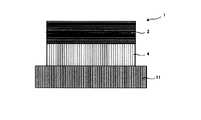
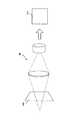
図1は、本実施形態のホログラム構造体1の原理を示す図である。 FIG. 1 is a diagram showing the principle of the hologram structure 1 of the present embodiment.
本実施形態では、ホログラム構造体1は、カード等の被着体11に接着され、セキュリティ媒体10を構成する。ホログラム構造体1は、絵柄及び文字等が形成された印刷層3に撮像部30の焦点が合った際に、ホログラム層2が撮像部30の被写界深度内になるように、ホログラム層2と印刷層3が近接して形成される。このように、撮像部30の焦点が印刷層3にあうと、撮像部30の被写界深度内にホログラム層2が配置されているので、ホログラム層2と印刷層3の両方が複製された複製品12を作製することが可能となる。 In the present embodiment, the hologram structure 1 is adhered to an
一般に複写機に適用される撮像部30の被写界深度は、50μmより大きく設定されているものが多い。
したがって、本実施形態では、ホログラム層2と印刷層3の間の距離を50μm以下とすることが好ましい。In many cases, the depth of field of the
Therefore, in the present embodiment, the distance between the
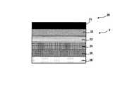
図2は、本実施形態のホログラム層2に用いるホログラム転写箔20の一例を示す図である。 FIG. 2 is a diagram showing an example of the
本実施形態のホログラム層2に用いるホログラム転写箔20は、基材フィルム21に、剥離層22、保護層23、及びホログラム形成層24を、それぞれ順に塗布及び乾燥させて形成し、ホログラム効果層25を蒸着した後、接着層26を塗布及び乾燥させて形成する。 The
基材フィルム21は、通常厚み約12〜100μm程度の透明または不透明のポリエチレンテレフタレートフィルム、またはポリエチレンナフタレートフィルムである。剥離層(離型層)22は、必要に応じて適当な離型剤を含むアクリル系樹脂などから厚み約0.5〜4μm程度に形成する。保護層(プライマー層)23はポリエステル樹脂やアクリル樹脂などの溶液から厚み約0.2〜1.0μm程度に形成する。ホログラム形成層24は、好ましくは紫外線硬化性または電子線硬化性樹脂から厚み約1〜10μm程度に形成し、ホログラムの凹凸形状(回折格子)を、原版を用いてエンボスなどで表面に形成し、その後に完全硬化させる。ホログラム効果層25は、アルミニウムの蒸着、金属酸化物や金属硫化物などのスパッタリングや蒸着などにより厚み約100〜2,000Å(=10〜200nm)程度に形成する。 The
上記ホログラム転写箔20に用いる接着層26としては、ポリイソシアネート、ポリオールおよび触媒を使用直前に混合して使用する2液硬化型のウレタン系接着剤やエポキシ系接着剤などの2液硬化型接着剤の使用が望ましい。ウレタン系などの2液硬化型の接着層26を用いる場合には、使用直前に決められた処方に従ってA液、B液および触媒を混合して厚み約3〜8μm(固形分)程度に接着層6を形成し、所定時間内にホログラム転写箔20からラミネーターを用いて被着体11にラミネートしてホログラム層2を転写する。なお、基材フィルム21は、転写後剥離される。 The
図3は、第1実施形態のホログラム構造体1の一例を示す図である。 FIG. 3 is a diagram showing an example of the hologram structure 1 of the first embodiment.
第1実施形態のホログラム構造体1は、被着体11の表面に印刷層3を形成し、その上にホログラム層2を形成する。したがって、表面からの層の順は、ホログラム層2、印刷層3、被着体11となる。ホログラム層2の厚さt2は、0.5μm≦t2≦25μmが好ましい。また、印刷層3の厚さt3は、1μm≦t3≦5μmが好ましい。 In the hologram structure 1 of the first embodiment, the
第1実施形態のホログラム構造体1を、図1に示したようにコピー機等で複製した場合、撮像部30の焦点が印刷層3に合うと、撮像部30の被写界深度内にホログラム層2が配置されているので、ホログラム層2と印刷層3の両方を複製することが可能となる。 When the hologram structure 1 of the first embodiment is duplicated by a copier or the like as shown in FIG. 1, when the focus of the
図4は、第2実施形態のホログラム構造体1の一例を示す図である。 FIG. 4 is a diagram showing an example of the hologram structure 1 of the second embodiment.
第2実施形態のホログラム構造体1は、被着体11の表面にホログラム層2を形成し、その上に印刷層3を形成する。したがって、表面からの層の順は、印刷層3、ホログラム層2、被着体11となる。ホログラム層2の厚さt2は0.5μm≦t2≦25μmが好ましい。また、印刷層3の厚さt3は、1μm≦t3≦5μmが好ましい。 In the hologram structure 1 of the second embodiment, the
第2実施形態のホログラム構造体1を、図1に示したようにコピー機等で複製した場合、撮像部30の焦点が印刷層3に合うと、撮像部30の被写界深度内にホログラム層2が配置されているので、ホログラム層2と印刷層3の両方を複製することが可能となる。 When the hologram structure 1 of the second embodiment is duplicated by a copier or the like as shown in FIG. 1, when the focus of the
図5は、第3実施形態のホログラム構造体1の一例を示す図である。 FIG. 5 is a diagram showing an example of the hologram structure 1 of the third embodiment.
第3実施形態のホログラム構造体1は、被着体11の表面に印刷層として、感熱発色層4を形成し、その上にホログラム層2を形成する。したがって、表面からの層の順は、ホログラム層2、感熱発色層4、被着体11となる。
ホログラム層2の厚さt2は0.5μm≦t2≦25μmが好ましい。
また、感熱発色層4の厚さt4は、1μm≦t4≦5μmが好ましい。In the hologram structure 1 of the third embodiment, a heat-sensitive color-developing layer 4 is formed as a printing layer on the surface of the
The thickness t2 of the
Further, the thickness t4 of the heat-sensitive color-developing layer 4 is preferably 1 μm ≦ t4 ≦ 5 μm.
第1実施形態のホログラム構造体1を、図1に示したようにコピー機等で複製した場合、撮像部30の焦点が感熱発色層4に合うと、撮像部30の被写界深度内にホログラム層2が配置されているので、ホログラム層2と感熱発色層4の両方を複製することが可能となる。 When the hologram structure 1 of the first embodiment is duplicated by a copier or the like as shown in FIG. 1, when the focus of the
図6は、第4実施形態のホログラム構造体1の一例を示す図である。 FIG. 6 is a diagram showing an example of the hologram structure 1 of the fourth embodiment.
第4実施形態のホログラム構造体1は、被着体11の表面に印刷層3を形成し、その上に透明なカバー層5を形成し、その上にホログラム層2を形成する。したがって、表面からの層の順は、ホログラム層2、カバー層5、印刷層3、被着体11となる。
ホログラム層2の厚さt2は0.5μm≦t2≦25μmが好ましい。
また、印刷層3の厚さt3は、1μm≦t3≦5μmが好ましい。
さらに、カバー層5の厚さは、50μm以下が好ましい。In the hologram structure 1 of the fourth embodiment, the
The thickness t2 of the
The thickness t3 of the
Further, the thickness of the
第4実施形態のホログラム構造体1を、図1に示したようにコピー機等で複製した場合、撮像部30の焦点が印刷層3に合うと、撮像部30の被写界深度内にホログラム層2が配置されているので、ホログラム層2と印刷層3の両方を複製することが可能となる。また、ホログラム層2及び印刷層3を的確に保持することが可能となる。 When the hologram structure 1 of the fourth embodiment is duplicated by a copier or the like as shown in FIG. 1, when the focus of the
次に、印刷層3の分布について説明する。 Next, the distribution of the
図7は、本実施形態のホログラム構造体1の印刷層3の一例を示す。 FIG. 7 shows an example of the
本実施形態の印刷層3は、ホログラム構造体1の全面を印刷する必要はない。例えば、図7に示すように、印刷層3の絵柄の面積が全体の15%以上となる連続地紋であればよい。このように、印刷層3の絵柄の面積が全体の15%以上となる連続地紋であれば、複写機の焦点を印刷層3にあわせることが可能となる。 The
図8は、本実施形態のホログラム構造体1の印刷層3の他の例を示す。 FIG. 8 shows another example of the
本実施形態の他の例は、ホログラム構造体1の端縁に印刷層3を形成したものである。このように印刷層3を形成することで、複写機の走査方向が縦、横、又は斜めのいずれであっても印刷層3に焦点をあわせることが可能となる。なお、ホログラム構造体1の端縁全てに印刷層3を形成する必要はなく、少なくとも向かい合う辺のどちらか一つに形成すればよい。例えば、隣り合う端縁に沿ってL字状に形成してもよい。 In another example of this embodiment, the
なお、印刷層3は、プリンタ等によって印刷したもの、自筆のもの、感熱発色したもの等のいずれでもよい。 The
このように、本実施形態のホログラム構造体1は、少なくとも絵柄及び文字のいずれかが再生されるホログラム層2と、少なくとも絵柄及び文字のいずれかが形成された印刷層3と、を有し、印刷層3とホログラム層2は、隣接して形成されるので、デザイン性に優れ、複写機等によって複製できることで、真正であることを判定することが可能となる。 As described above, the hologram structure 1 of the present embodiment has a
また、本発明にかかるホログラム構造体1では、
ホログラム層2の厚さt2は、0.5μm≦t2≦25μmであり、
印刷層3の厚さt3は、1μm≦t3≦5μmであるので、
撮像部30の焦点が印刷層3にあうと、撮像部30の被写界深度内にホログラム層2が配置されているので、ホログラム層2と印刷層3の両方を複製することが可能となる。Further, in the hologram structure 1 according to the present invention,
The thickness t2 of the
Since the thickness t3 of the
When the focus of the
また、本発明にかかるホログラム構造体1では、ホログラム層2と印刷層3の間の距離は、50μm以下であるので、撮像部30の焦点が印刷層3にあうと、一般の複写機の撮像部30の被写界深度内にホログラム層2が配置されることとなり、ホログラム層2と印刷層3の両方を複製することが可能となる。 Further, in the hologram structure 1 according to the present invention, the distance between the
また、本発明にかかるホログラム構造体1は、ホログラム層2と印刷層3の間に透明なカバー層5を有するので、ホログラム層2及び印刷層3を的確に保持することが可能となる。 Further, since the hologram structure 1 according to the present invention has a
また、本発明にかかるホログラム構造体1では、印刷層3は、絵柄の面積が全体の
15%以上となる連続地紋であるので、複写機の焦点を容易に印刷層3にあわせることが可能となる。Further, in the hologram structure 1 according to the present invention, since the
また、本発明にかかるホログラム構造体1では、印刷層3は、少なくとも向かい合う辺のどちらか一つの端縁に形成されるので、複写機の走査方向が縦、横、又は斜めのいずれであっても印刷層3に焦点をあわせることが可能となる。 Further, in the hologram structure 1 according to the present invention, since the
また、本発明にかかるセキュリティ媒体10は、前記ホログラム構造体1と、ホログラム構造体1を接着する被着体11と、を備えるので、デザイン性に優れ、複写機等によって複製できることで、真正であることを判定することが可能となる。 Further, since the
以上、ホログラム構造体及びセキュリティ媒体をいくつかの実施例に基づいて説明してきたが、本発明はこれら実施例に限定されず種々の組み合わせ又は変形が可能である。 Although the hologram structure and the security medium have been described above based on some examples, the present invention is not limited to these examples, and various combinations or modifications are possible.
1…ホログラム構造体
2…ホログラム層
3…印刷層
4…感熱発色層
5…カバー層
10…セキュリティ媒体
11…被着体
12…複製品
30…撮像部
1 ...
Claims (1)
Translated fromJapanese表面からの層順は、前記印刷層、前記ホログラム層、前記被着体となっており、前記印刷層の厚さは1μm以上5μm以下、前記ホログラム層の厚さは0.5μm以上25μm以下、そして、前記ホログラム層と前記印刷層の間の距離は50μm以下にそれぞれなっており、
前記ホログラム層の少なくとも向かい合う辺のどちらか一つの端縁に前記印刷層を形成することで、複写機等で複写した場合に当該複写機等の撮影部が焦点を合わせることができる層として前記印刷層を配置し、かつ、前記焦点に対する前記撮影部の被写界深度内に前記ホログラム層を配置し、当該複写機等による複写により、前記ホログラム層の上層に形成した前記印刷層からの複製と、前記印刷層が上層に形成された前記ホログラム層からの複製の両方がそれぞれ真正を判定できる状態で複製されるようにした、
ことを特徴とするセキュリティ媒体。
In a security medium having an adherend, a print layer provided on the adherend on which at least one of a pattern and characters is formed, and a hologram layer on which at least one of the patterns and characters is reproduced.
The layer order from the surface is the print layer, the hologram layer, and the adherend. The thickness of the print layer is 1 μm or more and 5 μm or less, and the thickness of the hologram layer is 0.5 μm or more and 25 μm or less. The distance between the hologram layer and the printing layer is 50 μm or less, respectively.
By forming the printing layer on the edge of at least one of the opposite sides of the hologram layer, the printing is performed as a layer on which the photographing unit of the copying machine or the like can focus when copying is performed by the copying machine or the like. the layers were arranged, and the hologram layeris arranged within the depth of field of the imaging unit with respect to the focal point, the copying by the copier, and replication from said printinglayer formed on an upper layer of the hologram layer , Both of the duplicates from the hologram layerin which the print layer is formed on the upper layer are duplicated in astate where the authenticity can be determined.
A security medium characterized by that.
Priority Applications (1)
| Application Number | Priority Date | Filing Date | Title |
|---|---|---|---|
| JP2018137090AJP6879271B2 (en) | 2018-07-20 | 2018-07-20 | Security medium |
Applications Claiming Priority (1)
| Application Number | Priority Date | Filing Date | Title |
|---|---|---|---|
| JP2018137090AJP6879271B2 (en) | 2018-07-20 | 2018-07-20 | Security medium |
Related Parent Applications (1)
| Application Number | Title | Priority Date | Filing Date |
|---|---|---|---|
| JP2014040607ADivisionJP2015166760A (en) | 2014-03-03 | 2014-03-03 | Hologram structure and security medium |
Publications (2)
| Publication Number | Publication Date |
|---|---|
| JP2018165058A JP2018165058A (en) | 2018-10-25 |
| JP6879271B2true JP6879271B2 (en) | 2021-06-02 |
Family
ID=63922640
Family Applications (1)
| Application Number | Title | Priority Date | Filing Date |
|---|---|---|---|
| JP2018137090AActiveJP6879271B2 (en) | 2018-07-20 | 2018-07-20 | Security medium |
Country Status (1)
| Country | Link |
|---|---|
| JP (1) | JP6879271B2 (en) |
Family Cites Families (11)
| Publication number | Priority date | Publication date | Assignee | Title |
|---|---|---|---|---|
| JPS59120491A (en)* | 1982-12-28 | 1984-07-12 | Dainippon Printing Co Ltd | Prevention of forgery by copying |
| JPH0679195B2 (en)* | 1985-12-04 | 1994-10-05 | 大日本印刷株式会社 | Hologram transfer sheet with picture |
| JP3458470B2 (en)* | 1994-08-22 | 2003-10-20 | 凸版印刷株式会社 | Diffraction grating pattern |
| JPH09220892A (en)* | 1996-02-19 | 1997-08-26 | Toppan Printing Co Ltd | Diffraction grating pattern with copy protection and article to which it is applied |
| JPH10278462A (en)* | 1997-04-10 | 1998-10-20 | Dainippon Printing Co Ltd | Counterfeit prevention ticket |
| JP3075238U (en)* | 2000-07-28 | 2001-02-16 | 小林記録紙株式会社 | Imprint duplication prevention form |
| JP4662643B2 (en)* | 2001-01-29 | 2011-03-30 | 共同印刷株式会社 | Ticket and ticket manufacturing method |
| JP4587809B2 (en)* | 2002-08-13 | 2010-11-24 | ギーゼッケ ウント デフリエント ゲーエムベーハー | Data carrier with optically variable element |
| JP4915199B2 (en)* | 2006-10-11 | 2012-04-11 | 大日本印刷株式会社 | Forgery prevention medium using intermediate transfer recording medium with hologram |
| JP2010197666A (en)* | 2009-02-25 | 2010-09-09 | Toppan Printing Co Ltd | Hologram sheet |
| JP5806103B2 (en)* | 2011-12-20 | 2015-11-10 | 三菱電機株式会社 | Image reading device |
- 2018
- 2018-07-20JPJP2018137090Apatent/JP6879271B2/enactiveActive
Also Published As
| Publication number | Publication date |
|---|---|
| JP2018165058A (en) | 2018-10-25 |
Similar Documents
| Publication | Publication Date | Title |
|---|---|---|
| JP4478346B2 (en) | Image forming method and intermediate transfer recording medium | |
| US8505979B2 (en) | Method for producing a data carrier and data carrier produced therefrom | |
| JP2001315472A (en) | Information recording medium and card having light diffraction structure, and light diffraction structure | |
| JP7115473B2 (en) | INFORMATION RECORDING MEDIUM, LABEL, CARD, AND AUTHENTICITY DETERMINATION METHOD | |
| JP5521475B2 (en) | Image forming body manufacturing method, image forming body, personal authentication medium manufacturing method, and personal authentication medium | |
| CN1193299A (en) | Fake document with writable transparent hologram | |
| JP2013092746A (en) | Image display body and information medium | |
| US3967400A (en) | Identification card | |
| JP6879271B2 (en) | Security medium | |
| JP2011039336A (en) | Personal authentication medium | |
| EP2612763B2 (en) | Identity document with secure image | |
| JP5609070B2 (en) | Image forming body manufacturing method, image forming body, personal authentication medium manufacturing method, and personal authentication medium | |
| JP2012173464A (en) | Production method for image forming body, image forming body, and personal authentication medium | |
| JP7009794B2 (en) | Volumetric hologram laminate, manufacturing method of volume hologram laminate, and information recording medium | |
| JP5282514B2 (en) | Authenticity identifier | |
| CA2226029A1 (en) | Data storage medium | |
| JP3710963B2 (en) | Magnetic recording medium | |
| JP4686042B2 (en) | Anti-counterfeit magnetic transfer foil | |
| JP2002215010A (en) | Authenticator | |
| JP4170618B2 (en) | Authenticity identification method | |
| JP2001293982A (en) | Information recording medium and information recording card | |
| JP2015166760A (en) | Hologram structure and security medium | |
| KR102278913B1 (en) | Secure printed matter | |
| JP7697232B2 (en) | Anti-counterfeiting media | |
| JP7409111B2 (en) | shaped magnetic card |
Legal Events
| Date | Code | Title | Description |
|---|---|---|---|
| A621 | Written request for application examination | Free format text:JAPANESE INTERMEDIATE CODE: A621 Effective date:20180720 | |
| A977 | Report on retrieval | Free format text:JAPANESE INTERMEDIATE CODE: A971007 Effective date:20190726 | |
| A131 | Notification of reasons for refusal | Free format text:JAPANESE INTERMEDIATE CODE: A131 Effective date:20190820 | |
| A521 | Written amendment | Free format text:JAPANESE INTERMEDIATE CODE: A523 Effective date:20191008 | |
| A131 | Notification of reasons for refusal | Free format text:JAPANESE INTERMEDIATE CODE: A131 Effective date:20200317 | |
| A521 | Written amendment | Free format text:JAPANESE INTERMEDIATE CODE: A523 Effective date:20200507 | |
| A131 | Notification of reasons for refusal | Free format text:JAPANESE INTERMEDIATE CODE: A131 Effective date:20201020 | |
| A521 | Written amendment | Free format text:JAPANESE INTERMEDIATE CODE: A523 Effective date:20201208 | |
| TRDD | Decision of grant or rejection written | ||
| A01 | Written decision to grant a patent or to grant a registration (utility model) | Free format text:JAPANESE INTERMEDIATE CODE: A01 Effective date:20210330 | |
| A61 | First payment of annual fees (during grant procedure) | Free format text:JAPANESE INTERMEDIATE CODE: A61 Effective date:20210412 | |
| R150 | Certificate of patent or registration of utility model | Ref document number:6879271 Country of ref document:JP Free format text:JAPANESE INTERMEDIATE CODE: R150 |