JP6878028B2 - Medical image diagnostic system and mixed reality image generator - Google Patents
Medical image diagnostic system and mixed reality image generatorDownload PDFInfo
- Publication number
- JP6878028B2 JP6878028B2JP2017020315AJP2017020315AJP6878028B2JP 6878028 B2JP6878028 B2JP 6878028B2JP 2017020315 AJP2017020315 AJP 2017020315AJP 2017020315 AJP2017020315 AJP 2017020315AJP 6878028 B2JP6878028 B2JP 6878028B2
- Authority
- JP
- Japan
- Prior art keywords
- image
- interest
- ray
- mixed reality
- region
- Prior art date
- Legal status (The legal status is an assumption and is not a legal conclusion. Google has not performed a legal analysis and makes no representation as to the accuracy of the status listed.)
- Active
Links
Images


Landscapes
- Apparatus For Radiation Diagnosis (AREA)
Description
Translated fromJapanese本発明の実施形態は、医用画像診断システム及び複合現実画像生成装置に関する。 Embodiments of the present invention relate to a medical diagnostic imaging system and a mixed reality image generator.
モダリティや画像処理技術の革新により、被検体の内部を詳細に撮像することが可能となった。それに伴い、医用画像を用いた診断や手術計画は、医療において重要な役割を占めるようになった。例えば、医用画像から被検体内の治療対象が特定され、医用画像上で特定された治療対象が手術されることで、病気が治療される。患者を切開する手術の場合、医師は、医用画像上で確認される治療対象位置と、患者の体内にある実際の治療対象位置とを照合し、患者の切開位置や範囲などを特定する。 Innovations in modality and image processing technology have made it possible to take detailed images of the inside of a subject. Along with this, diagnosis and surgical planning using medical images have come to play an important role in medical treatment. For example, a disease is treated by identifying a treatment target in a subject from a medical image and performing an operation on the treatment target specified on the medical image. In the case of surgery to make an incision in a patient, the doctor collates the position of the treatment target confirmed on the medical image with the actual position of the treatment target in the patient's body, and identifies the incision position and range of the patient.
しかしながら、患者の体内を撮像した医用画像において観察される治療対象位置を、患者を体外から観察して正確に特定するには、熟練の技術や解剖学的な知識が無ければ困難である。 However, it is difficult to accurately identify the position of the treatment target observed in the medical image of the inside of the patient by observing the patient from outside the body without skill and anatomical knowledge.
近年、拡張現実(Augmented Reality)や複合現実(Mixed Reality)といった画像の表現方法に関する新しい技術が開発され、医用画像の診断や治療計画の支援への応用が期待されている。 In recent years, new technologies related to image representation methods such as Augmented Reality and Mixed Reality have been developed, and are expected to be applied to the diagnosis of medical images and the support of treatment planning.
本発明が解決しようとする課題は、医用画像上で特定された被検体の治療対象位置を従来とは異なる方法で認識可能な医用画像診断システム及び複合現実画像生成装置を提供することである。 An object to be solved by the present invention is to provide a medical image diagnosis system and a mixed reality image generation device capable of recognizing a treatment target position of a subject specified on a medical image by a method different from the conventional method.
一実施形態に係る医用画像診断システムは、照射機構から照射されて被検体を透過したX線を検出器によって検出することで前記被検体のX線画像を生成する撮像部と、ディスプレイ及び位置姿勢センサを有し、前記ディスプレイがユーザの視野に含まれるように前記ユーザの頭部に対して装着される表示部と、前記撮像部により生成された前記X線画像に対して設定された関心領域の位置と、前記X線画像の生成時の前記照射機構及び前記検出器の配置状態とに応じて、前記撮像部の設置室における前記関心領域の3次元位置を特定する特定部と、前記位置姿勢センサによって検出される前記表示部の位置及び姿勢を前記表示部から順次取得し、前記表示部の位置及び姿勢と、前記関心領域の3次元位置とに応じて、前記ディスプレイと前記関心領域との位置関係に整合するように、前記関心領域の3次元位置を前記ディスプレイ上で示す画像データを順次生成し、前記画像データを前記表示部に順次送信する処理部と、を備える。 The medical diagnostic imaging system according to the embodiment includes an imaging unit that generates an X-ray image of the subject by detecting X-rays that have been irradiated from the irradiation mechanism and transmitted through the subject by a detector, a display, and a position / orientation. A display unit having a sensor and mounted on the user's head so that the display is included in the user's field of view, and a region of interest set for the X-ray image generated by the imaging unit. A specific portion that specifies a three-dimensional position of the region of interest in the installation room of the imaging unit, and the position according to the position of the above and the arrangement state of the irradiation mechanism and the detector at the time of generating the X-ray image. The position and orientation of the display unit detected by the attitude sensor are sequentially acquired from the display unit, and the display and the region of interest are obtained according to the position and orientation of the display unit and the three-dimensional position of the region of interest. A processing unit that sequentially generates image data indicating the three-dimensional position of the region of interest on the display and sequentially transmits the image data to the display unit is provided so as to match the positional relationship of the above.
以下、医用画像診断システム及び複合現実画像生成装置の各実施形態について図面を参照して説明する。 Hereinafter, each embodiment of the medical image diagnosis system and the mixed reality image generator will be described with reference to the drawings.
[第1の実施形態]
(1)構成
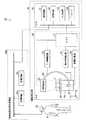
図1は、第1の実施形態に係る医用画像診断システムの一例を示す概念的な構成図である。図1に示すように医用画像診断システム1Aは、X線診断装置10、複合現実画像生成装置40a、及び複合現実画像表示装置50を備える。[First Embodiment]
(1) Configuration FIG. 1 is a conceptual configuration diagram showing an example of a medical image diagnosis system according to the first embodiment. As shown in FIG. 1, the medical
ここで、複合現実画像とは、複合現実空間内の物体を描出した画像である。なお、複合現実空間とは、現実空間と仮想空間とを融合させて、現実空間の物体と仮想空間の物体とがリアルタイムで影響しあう新たな空間のことである。例えば、被検体の治療対象を被検体の医用画像から特定された仮想空間上の物体とし、検査室に存在する被検体を現実空間における物体とする。この場合、複合現実空間は、現実空間の被検体と仮想空間上の治療対象との関係をリアルタイムに示す空間である。従って、複合現実画像とは、例えば、リアルタイムで順次生成されて更新される被検体画像に対して、被検体の治療対象位置が重畳された画像である。 Here, the mixed reality image is an image depicting an object in the mixed reality space. The mixed reality space is a new space in which an object in the real space and an object in the virtual space influence each other in real time by fusing the real space and the virtual space. For example, the treatment target of the subject is an object in the virtual space specified from the medical image of the subject, and the subject existing in the laboratory is an object in the real space. In this case, the mixed reality space is a space that shows the relationship between the subject in the real space and the treatment target in the virtual space in real time. Therefore, the mixed reality image is, for example, an image in which the treatment target position of the subject is superimposed on the subject image that is sequentially generated and updated in real time.
複合現実画像生成装置40aは、検査室に設置されてもよいし、検査室に隣接する制御室に設置されてもよい。複合現実画像表示装置50は、例えば、医師等のユーザQが頭部に装着して使用される。 The mixed reality
X線診断装置10は、スキャナ20及びコンソール30を備える。スキャナ20は、検査室に設置される。コンソール30は、検査室又は制御室に設置される。 The X-ray
スキャナ20は、コントローラ21、アーム制御回路22、寝台制御回路23、高電圧電源24、X線検出器25、Cアーム26、X線管27、天板28、及び寝台29を備える。 The
コントローラ21は、不図示のCPU(Central Processing Unit)などのプロセッサ及びメモリを備える。コントローラ21は、アーム制御回路22、寝台制御回路23、高電圧電源24、及びX線検出器25を制御し、撮像動作を統括する。 The
また、コントローラ21は、アーム制御回路22及び寝台制御回路23を介して、X線検出器25、Cアーム26、X線管27、天板28、及び寝台29などのスキャナ20を構成する各装置の配置状態を制御する。 Further, the
ここで配置状態とは、スキャナ20を構成する各装置のモダリティ座標系における位置のことである。コントローラ21は、スキャナ20を構成する各装置の撮像時におけるモダリティ座標を記憶する。 Here, the arrangement state is a position in the modality coordinate system of each device constituting the
ここでモダリティ座標系とは、X線診断装置10の装置座標系のことである。ここでは一例としてモダリティ座標系のx軸、y軸、z軸を以下のように定義する。即ち、鉛直方向をy軸方向とし、y軸方向に垂直であって、天板28の長軸方向に平行な方向をz軸方向とし、これらy軸方向及びz軸方向に垂直な方向をx軸方向とする。 Here, the modality coordinate system is the device coordinate system of the X-ray
アーム制御回路22は、コントローラ21の制御の下、被検体Pの撮像領域に応じてCアーム26を移動及び回転させる。 The
寝台制御回路23は、コントローラ21の制御の下、天板28及び寝台29を移動させる。 The
高電圧電源24は、コントローラ21の制御の下、X線の照射に必要な電力をX線管27に供給する。 The high-
X線検出器25は、天板28上に載置された被検体Pを間に挟んでCアーム26の一端に設けられたX線管27に対向するように、Cアーム26の他端に設けられる。X線検出器25及びX線管27は、アーム制御回路22からの指令によるCアーム26の動作により一体的に移動及び回転する。 The
X線検出器25は、例えば、不図示のマトリクス状に配列された多数のX線検出素子によって、被検体Pを透過したX線を検出する。各X線検出素子で検出されたX線信号は、電気信号に変換され投影データとしてコントローラ21を介してコンソール30に送信される。 The
なお、図1では、Cアーム26がX線管27を天板28の下方、即ち、床面側に位置するように支持するアンダーチューブタイプの場合を例示したが、これは一例に過ぎない。Cアーム16は、X線管27を天板28の上方、即ち、天井側に位置するよう支持するオーバーチューブタイプであってもよい。 Note that FIG. 1 illustrates a case of an undertube type in which the C-
また、図1では、撮像系がCアーム26のみであるシングルプレーンシステムのX線診断装置10を示すが、これは一例に過ぎない。X線診断装置10は、2つの撮像系を備えるバイプレーンシステムで構成されてもよい。バイプレーンシステムは、例えば、撮像系としてCアームを2つ備え、被検体Pを2方向から同時に撮像できる。 Further, FIG. 1 shows an X-ray
X線管27は、高電圧電源24から供給される高電圧によりX線を発生させる。X線管27から放射されるX線は、被検体Pの所定部位に向かって照射される。X線管27のX線の出射側には、例えば、複数枚の鉛羽で構成されるX線照射野絞りや、シリコンゴム等で形成された補償フィルタ等の照射調整機構が設けられる(図示せず)。 The
寝台29は、床面に設置され天板28を支持する。天板28は、寝台制御回路23の制御の下、鉛直方向であるy軸に垂直なxz面内方向を水平移動し、y軸方向に上下移動する。なお、医用画像診断システム1Aにおいて、天板28は、手術台としての機能も有する。 The
コンソール30は、コントローラ21から入力された投影データを再構成処理してX線画像を生成する。コンソール30は、処理回路31、記憶回路32、入力回路33、及びディスプレイ34を備える。 The
処理回路31は、共通信号伝送路としてのバスを介して、コンソール30を構成する各ハードウェア構成要素に相互接続されている。なお、コンソール30は、記憶媒体ドライブを具備する場合もある。 The
処理回路31は、専用のハードウェアで構成してもよいし、内蔵のプロセッサによるソフトウェア処理で後述する各種機能を実現するように構成してもよい。ここでは一例として、処理回路31がプロセッサによるソフトウェア処理によって各種機能を実現する場合について説明する。 The
なお、上記説明におけるプロセッサとは、専用又は汎用のCPU(Central Processing Unit)、GPU(Graphics Processing Unit)、特定用途向け集積回路(ASIC:Application Specific Integrated Circuit)、プログラマブル論理デバイス、及びフィールドプログラマブルゲートアレイ(FPGA:Field Programmable Gate Array)などの回路を意味する。上記プログラマブル論理デバイスとしては、例えば、単純プログラマブル論理デバイス(SPLD:Simple Programmable Logic Device)、複合プログラマブル論理デバイス(CPLD:Complex Programmable Logic Device)などが挙げられる。処理回路31は、記憶回路32に記憶されたプログラム又は処理回路31のプロセッサ内に直接組み込まれたプログラムを読み出し実行することで、各機能を実現する。 The processors in the above description include a dedicated or general-purpose CPU (Central Processing Unit), a GPU (Graphics Processing Unit), an application specific integrated circuit (ASIC), a programmable logic device, and a field programmable gate array. It means a circuit such as (FPGA: Field Programmable Gate Array). Examples of the programmable logic device include a simple programmable logic device (SPLD: Simple Programmable Logic Device) and a compound programmable logic device (CPLD: Complex Programmable Logic Device). The
また、処理回路31は、単一のプロセッサによって構成されてもよいし、複数の独立したプロセッサの組み合わせによって構成されてもよい。後者の場合、複数のプロセッサに夫々対応する複数の記憶回路32が設けられると共に、各プロセッサにより実行されるプログラムが当該プロセッサに対応する記憶回路に記憶される構成でもよい。別の例としては、1個の記憶回路32が複数のプロセッサの各機能に対応するプログラムを一括的に記憶する構成でもよい。 Further, the
記憶回路32は、例えば、RAM(Random Access Memory)、フラッシュメモリ(Flash Memory)などの半導体メモリ素子、ハードディスク、光ディスクなどによって構成される。記憶回路32は、USB(Universal Serial Bus)メモリ及びDVD(Digital Video Disk)などの可搬型メディアを着脱自在な回路として構成されてもよい。記憶回路32は、処理回路31において実行される各種プログラムの他、OS(Operating System)等のプログラムの実行に必要なデータ及び画像データを記憶する。また、記憶回路32は、OSを制御するための各種コマンドや、入力回路33からの入力を支援するGUI(Graphical User Interface)のプログラムを記憶してもよい。 The
入力回路33は、例えば、キーボード、マウス、ジョイスティック又はトラックボール等の入力デバイスを含む。入力回路33は、入力デバイスを介して操作者により入力された入力信号を処理回路31に出力する。ユーザQは、入力回路33を介してX線画像に関心領域(Region Of Interest:以下、ROIと略記する)を設定する。ROIは、異常が観察される部位や治療対象位置を含む医用画像上の領域のことである。 The
ディスプレイ34は、液晶ディスプレイパネル、プラズマディスプレイパネル、及び有機EL(Electro Luminescence)パネル等の表示デバイスである。ディスプレイ34は、処理回路31の制御に従ってX線画像を表示する。 The
複合現実画像生成装置40aは、コンソール30及び複合現実画像表示装置50に有線又は無線で接続される。複合現実画像生成装置40aは、コンソール30及び複合現実画像表示装置50からの入力内容に応じて複合現実画像を生成する。 The mixed reality
複合現実画像生成装置40aは、処理回路41a及び記憶回路42を備える。処理回路41a及び記憶回路42のハードウェア構成は、コンソール30の処理回路31及び記憶回路32と同様でよいので詳細な説明を省略する。 The mixed reality
なお、図1では、複合現実画像表示装置50とは別体として複合現実画像生成装置40aが設けられる例を示したが、複合現実画像生成装置40aは、複合現実画像表示装置50と一体的に構成されてもよい。例えば、複合現実画像生成装置40aの機能を全て搭載した集積回路(IC:integrated circuit)チップを複合現実画像表示装置50が備えてもよい。この場合、複合現実画像表示装置50は、コンソール30に無線又は有線で接続される。 Although FIG. 1 shows an example in which the mixed reality
複合現実画像表示装置50は、複合現実画像生成装置40aで生成された複合現実画像を表示する。 The mixed reality
以下、複合現実画像表示装置50がビデオシースルータイプのヘッドマウントディスプレイ(Head Mounted Display:以下、HMDと略記する)である場合を例として説明する。 Hereinafter, a case where the mixed reality
図2は、第1の実施形態に係る医用画像診断システム1Aの機能構成例を示すブロック図である。図2に示すように、複合現実画像表示装置50は、位置姿勢センサ51、カメラ52、及びディスプレイ53を備えるHMDである。複合現実画像表示装置50は、例えば、メガネ、ゴーグル又はヘルメットのようにユーザQの頭部に装着可能に構成されている。 FIG. 2 is a block diagram showing a functional configuration example of the medical
位置姿勢センサ51は、磁気センサ、ジャイロセンサ又は超音波センサのうち少なくとも1つで構成される。位置姿勢センサ51は、複合現実画像表示装置50の位置及び姿勢をリアルタイムに検出する。ここでの姿勢とは、複合現実画像表示装置50の傾きであり、例えば、複合現実画像表示装置50の第1の基準点、第2の基準点とを結ぶ直線の方向で規定することができる。ここでは一例として、後述の表示装置座標系におけるRXd軸周りの角度と、RYd軸周りの角度と、RZd軸周りの角度とで、複合現実画像表示装置50の姿勢が規定されるものとする。なお、位置姿勢センサ51は、複合現実画像表示装置50の位置及び姿勢をリアルタイムで検出可能であれば、位置及び姿勢の検出方法は特定の方法に限定されるものではない。 The position /
位置姿勢センサ51が磁気センサで構成される場合、磁気センサは、検査室内に設置されたトランスミッタが発生させた磁界の変化を検出する。トランスミッタ及び磁気センサは、夫々3方向の直交コイルで構成されており、トランスミッタの3つのコイルが順に励磁されると、磁気センサの3つのコイルには起電力が順次発生する。この磁気センサの各コイルの起電力を計測することで、複合現実画像表示装置50の検査室内における位置と姿勢(向き)が検出される。即ち、磁気センサの3つのコイルに対応する3軸により複合現実画像表示装置50の位置が検出され、当該3軸を夫々中心とした回転方向によって現実画像表示装置50の姿勢が検出される。 When the position /
カメラ52は、ユーザQの視点から見た被検体Pのカメラ画像をリアルタイムで取得する。カメラ52は、カメラの光軸とユーザQの視線方向とが一致するように設けられる。また、カメラ52は、1対で構成され、ユーザQの左右の目の視野を夫々別々に取得してもよい。 The
ディスプレイ53は、複合現実画像表示装置50がユーザQの頭部に装着されたときにユーザQの眼前に位置し、ユーザQの視野を覆うように構成されている。例えば、ユーザの目を完全に覆う没入型のHMDでは、眼前だけではなく、目の横や上下にもディスプレイが設けられる場合がある。また、HMDには、片方の目にディスプレイが設けられた単眼型の場合もある。このように、ディスプレイ53は、ユーザQの視野を含む位置に配置される。ディスプレイ53は、液晶ディスプレイなどの表示デバイスで構成される。ディスプレイ53は、左右の目に夫々対応するディスプレイに夫々異なる画像を表示し、視差効果により奥行方向が表現された視差画像を表示する。 The
HMDには、光学シースルータイプとカメラシースルータイプとがある。光学シースルータイプは、ディスプレイが透明又は半透明で、ユーザQは、ディスプレイを介して直接的に前方を観察できる。一方、ビデオシースルータイプは、ディスプレイが不透明で、カメラ52により取得されたカメラ画像をディスプレイに表示する。ユーザQは、ディスプレイに表示されたカメラ画像を介して間接的に前方を観察できる。ここでの前方とは、ディスプレイを基準としてユーザQの両目とは反対側であるディスプレイの前方のことである。 There are two types of HMDs, an optical see-through type and a camera see-through type. In the optical see-through type, the display is transparent or translucent, and the user Q can directly observe the front through the display. On the other hand, in the video see-through type, the display is opaque, and the camera image acquired by the
コンソール30の処理回路31は、画像再構成機能311及びROI設定機能312を実現する。画像再構成機能311及びROI設定機能312は、記憶回路32に格納されているプログラムを処理回路31のプロセッサが実行することによって実現される機能である。 The
画像再構成機能311は、スキャナ20のコントローラ21から入力された投影データに基づいてX線画像を再構成する。再構成されたX線画像は、ディスプレイ34に表示される。 The
また、画像再構成機能311は、被検体PのX線画像を撮像した時のスキャナ20を構成する各装置の配置状態を取得する。なお、配置状態は、投影データの付帯情報として投影データと共に画像再構成機能311に入力されてもよいし、投影データと関連付けされた別のデータとして投影データと共に画像再構成機能311に入力されてもよい。 In addition, the
更に、画像再構成機能311は、再構成されたX線画像の付帯情報に配置状態を付与してもよい。即ち、再構成されたX線画像は、付帯情報として当該X線画像の撮像時におけるスキャナ20を構成する各装置のモダリティ座標を有する。 Further, the
ROI設定機能312は、X線画像にROIを設定する。ROIは、例えば、ディスプレイ34に表示されたX線画像に基づいてユーザQにより入力される。ROI設定機能312は、入力回路33を介してユーザQによるROIの入力を受け付け、当該ROIをX線画像に設定する。 The
なお、ROIの設定は、ユーザQの入力には限定されない。例えば、ROI設定機能312は、画像処理技術を用いてX線画像上の異常領域を自動抽出してもよい。また、1つの画像に複数のROIが設定されてもよい。ROI設定機能312は、ROIが設定されたX線画像を記憶回路32に格納する。 The ROI setting is not limited to the input of the user Q. For example, the
複合現実画像生成装置40aの処理回路41aは、ROI位置特定機能411a、位置姿勢特定機能412a、変換機能413a、及び複合現実画像生成機能414aを実現する。ROI位置特定機能411a、位置姿勢特定機能412a、変換機能413a、及び複合現実画像生成機能414aは、記憶回路42に格納されているプログラムを処理回路41aのプロセッサが実行することによって実現される機能である。 The
ROI位置特定機能411aは、ROIが設定されたX線画像をコンソール30から取得する。X線画像は、当該X線画像が撮像された時のスキャナ20を構成する各装置のモダリティ座標を有する。ROI位置特定機能411aは、X線画像が撮像された時のスキャナ20を構成する各装置のモダリティ座標に基づいて、モダリティ座標系におけるROIの3次元位置を特定する。ROI位置特定機能411aにおけるROIの3次元位置の特定方法の詳細については後述の図4で説明する。 The ROI
位置姿勢特定機能412aは、位置姿勢センサ51で検出された検出信号に基づいて、検査室内における複合現実画像表示装置50の位置及び姿勢(方向)を特定する。位置姿勢特定機能412aにより特定される複合現実画像表示装置50の位置及び姿勢の詳細については後述の図5で説明する。 The position /
変換機能413aは、ROI位置特定機能411aにより特定されたモダリティ座標系におけるROIの3次元位置を、複合現実画像表示装置50の位置及び姿勢に基づいてスクリーン座標系における位置に変換する。 The
ここでスクリーン座標系とは、3次元の座標系で示された座標を2次元の表示装置に表示するための2次元座標系のことである。スクリーン座標系のXs軸、Ys軸は、例えば、ディスプレイ53の表示面と平行であって、ディスプレイ53の中心位置を原点とした直交座標系で表される。変換機能413aでのモダリティ座標系におけるROIの3次元位置のスクリーン座標系への変換方法の詳細については、後述の図5で説明する。 Here, the screen coordinate system is a two-dimensional coordinate system for displaying the coordinates indicated by the three-dimensional coordinate system on the two-dimensional display device. The Xs and Ys axes of the screen coordinate system are represented by, for example, a Cartesian coordinate system parallel to the display surface of the
複合現実画像生成機能414aは、スクリーン座標系における位置に変換されたROIの位置をカメラ52で取得されたカメラ画像に重畳することで、複合現実画像を生成する。複合現実画像生成機能414aで生成される複合現実画像の詳細については、後述の図6及び図7で説明する。 The mixed reality
(2)動作
図3は、第1の実施形態に係る医用画像診断システム1Aの動作の一例を示すフローチャートである。以下、図3のフローチャートのステップ番号に従って、第1の実施形態に係る医用画像診断システム1Aの動作について図4を適宜参照しつつ説明する。(2) Operation FIG. 3 is a flowchart showing an example of the operation of the medical
図3のフローチャートでは、医用画像診断システム1Aが導入された手術室において、医師であるユーザQが被検体Pの心臓を手術する場合を例として説明する。例えば、ユーザQは、複合現実画像に表示された被検体PのROIの位置に基づいて被検体Pの切開位置を特定する。 In the flowchart of FIG. 3, a case where a user Q, who is a doctor, operates on the heart of a subject P in an operating room in which a medical
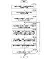
ステップST101において、X線診断装置10のスキャナ20は、天板28に載置された被検体Pを互いに異なる2方向から撮像し、第1のX線画像及び第2のX線画像の各投影データを生成する。画像再構成機能311は、スキャナ20で生成された投影データに基づいて、第1のX線画像の画像データ及び第2のX線画像の画像データを生成する。夫々のX線画像は、同一被検体の同一部位を互いに異なる方向から撮像した画像である。即ち、夫々のX線画像が付帯するスキャナ20を構成する各装置の配置状態は、第1のX線画像と第2のX線画像とで夫々異なる。 In step ST101, the
ステップST102において、ユーザQは、第1のX線画像及び第2のX線画像の夫々にROIを設定する。 In step ST102, the user Q sets the ROI for each of the first X-ray image and the second X-ray image.
ステップST103において、ROI位置特定機能411aは、第1のX線画像及び第2のX線画像に設定されたROIと、第1のX線画像及び第2のX線画像が撮像された時のスキャナ20を構成する各装置の配置状態とに基づいて、モダリティ座標系におけるROIの3次元位置を特定する。ROIの3次元位置は、例えば、ROIの中心位置のモダリティ座標系における3次元的な座標で示される。以下、モダリティ座標系におけるROIの中心位置を示す3次元座標を、ROIの3次元位置と称する。 In step ST103, the ROI
図4は、ROIの3次元位置を特定する方法を説明する模式図である。図4は、被検体Pの心臓をスキャナ20で2方向から撮像した場合におけるモダリティ座標系でのROIの3次元位置を特定する方法を模式的に示した図である。図4は、心臓の冠動脈血管の一部に閉塞が生じ、閉塞した冠動脈血管の一部がROIに含まれる場合を例として示している。図4の左側は、第1のX線画像を示しており、図4の下部は、第2のX線画像を示している。 FIG. 4 is a schematic diagram illustrating a method of identifying a three-dimensional position of the ROI. FIG. 4 is a diagram schematically showing a method of specifying the three-dimensional position of the ROI in the modality coordinate system when the heart of the subject P is imaged from two directions by the
第1のX線画像には、当該第1のX線画像上に観察される閉塞した冠動脈血管の一部を含むROI1が設定される。同様に第2のX線画像には、当該第2のX線画像上に観察される閉塞した冠動脈血管の一部を含むROI2が設定される。 In the first X-ray image, ROI1 including a part of the occluded coronary blood vessel observed on the first X-ray image is set. Similarly, in the second X-ray image, ROI2 including a part of the occluded coronary blood vessel observed on the second X-ray image is set.
第1のX線画像の付帯情報には、第1のX線画像の撮像時におけるX線管27及びX線検出器25のモダリティ座標が夫々含まれる。同様に、第2のX線画像の付帯情報には、当該第2のX線画像の撮像時におけるX線管27及びX線検出器25のモダリティ座標が夫々含まれる。スキャナ20を構成する各装置のモダリティ座標は、例えば、各装置の重心の位置を示す。 The incidental information of the first X-ray image includes the modality coordinates of the
モダリティ座標系におけるROIの中心位置の3次元的な座標は、第1のX線画像及び第2のX線画像から、例えば、以下のように特定される。ROI位置特定機能411aは、第1の撮像時におけるX線検出器25のモダリティ座標に基づいて、第1のX線画像に設定されたROIの中心位置のモダリティ座標を特定する。同様に、ROI位置特定機能411aは、第2の撮像時におけるX線検出器25のモダリティ座標に基づいて、第2のX線画像に設定されたROIの中心位置のモダリティ座標を特定する。 The three-dimensional coordinates of the center position of the ROI in the modality coordinate system are specified from the first X-ray image and the second X-ray image, for example, as follows. The ROI
第1のX線画像に設定されたROI1の中心位置を示すモダリティ座標と、第1の撮像時のX線管27の重心位置を示すモダリティ座標とを結んだ直線を直線L1とする。第2のX線画像に設定されたROI2の中心位置を示すモダリティ座標と、第2の撮像時のX線管27の重心位置を示すモダリティ座標とを結んだ直線を直線L2とする。この場合、直線L1と直線L2との交点であるROIの中心位置CRがROIの3次元位置として特定される。 The straight line L1 is a straight line connecting the modality coordinates indicating the center position of ROI1 set in the first X-ray image and the modality coordinates indicating the position of the center of gravity of the
このように、モダリティ座標系におけるROIの3次元位置は、X線画像が撮像された時のスキャナ20を構成する各装置のモダリティ座標から幾何学的に特定できる。 In this way, the three-dimensional position of the ROI in the modality coordinate system can be geometrically specified from the modality coordinates of each device constituting the
なお、図4では、説明を簡略化するためX線画像のサイズがX線検出器25の検出面のサイズと同じである場合を例として説明したが、X線画像のサイズについては図4の態様には限定されない。X線画像のサイズがX線検出器25の検出面のサイズより小さい場合であってもROI位置特定機能411aは、ROIの3次元位置を特定できる。 In FIG. 4, for simplification of the explanation, the case where the size of the X-ray image is the same as the size of the detection surface of the
例えば、X線検出器25の検出面の一部をX線の検出範囲とする撮像条件が設定される場合がある。撮像条件は、X線画像の画像データの付帯情報に含まれる。また、X線画像撮像時のX線検出器25の中心位置を示すモダリティ座標は、X線画像の画像データの付帯情報に含まれる。ROI位置特定機能411aは、X線検出器25の中心位置とX線検出器25の検出範囲とからX線画像に設定されたROIの中心位置のモダリティ座標を算出できる。特定された第1のX線画像及び第2のX線画像のROIの夫々の中心位置と、夫々の撮像時のX線管27の重心位置とを結ぶ直線L1、L2に基づいて、モダリティ座標系におけるROIの中心位置CRを特定できる。 For example, an imaging condition may be set in which a part of the detection surface of the
図3に戻って、フローチャートの説明を続ける。 Returning to FIG. 3, the explanation of the flowchart will be continued.
ステップST104において、位置姿勢特定機能412aは、位置姿勢センサ51で検出された検出信号に基づいて、カメラ画像撮像時の複合現実画像表示装置50の位置及び姿勢を特定する。 In step ST104, the position /
ステップST105において、変換機能413aは、複合現実画像表示装置50の位置及び姿勢に基づいて、モダリティ座標系におけるROIの3次元位置をスクリーン座標系における位置に変換する。 In step ST105, the
ステップST106において、複合現実画像生成機能414aは、カメラ52から取得されたカメラ画像に対してスクリーン座標系での位置に変換されたROIの位置が重畳された複合現実画像を生成する。なお、カメラ画像は、位置姿勢センサ51により複合現実画像表示装置50の位置及び姿勢が検出された時の画像である。複合現実画像表示装置50は、カメラ52のフレームレートと位置姿勢センサ51からの検出信号の測定間隔とを同期させるよう構成されてもよいし、カメラ画像と検出信号とを時間で関連付けて記録するように構成されてもよい。 In step ST106, the mixed reality
ステップST107において、ディスプレイ53は、複合現実画像を表示する。 In step ST107, the
ステップST108において、複合現実画像表示装置50は、複合現実画像の表示を終了するか否かを判定する。複合現実画像の表示を終了する場合、YESの方向に分岐し、表示終了処理が実行される。一方、複合現実画像の表示を継続する場合、NOの方向に分岐し、ステップST104に戻ってステップST104〜ST107の処理が再実行される。 In step ST108, the mixed reality
このように、複合現実画像の表示が終了されない限り、ステップST104〜ST107の処理が繰り返し実行され、複合現実画像表示装置50の位置及び姿勢に応じて複合現実画像が更新表示され続ける。なお、複合現実画像の更新タイミングは、一定間隔であってもよいし、カメラ画像のフレームレートや位置姿勢センサ51の検出間隔に同期していてもよい。また、複合現実画像表示装置50の位置及び姿勢が変化する度に複合現実画像が更新されるよう複合現実画像生成装置40aを構成してもよい。 In this way, unless the display of the mixed reality image is completed, the processes of steps ST104 to ST107 are repeatedly executed, and the mixed reality image is continuously updated and displayed according to the position and orientation of the mixed reality
以上がフローチャートの説明である。以下、複合現実画像の生成方法について図5を用いて補足する。 The above is the explanation of the flowchart. Hereinafter, the method of generating a mixed reality image will be supplemented with reference to FIG.
図5は、複合現実画像を生成する方法を説明する模式図である。図5の上段左側は、複合現実画像表示装置50の座標系である表示装置座標系を示している。図5の上段中央は、検査室座標系を示している。図5の上段右側は、モダリティ座標系を示している。図5の中段左側は、カメラ52で取得されたカメラ画像IMG1を示している。図5の中段右側は、スクリーン座標系を示している。図5の下段は、カメラ画像IMG1にROIの中心位置CRを重畳した複合現実画像IMG2を示している。 FIG. 5 is a schematic diagram illustrating a method of generating a mixed reality image. The upper left side of FIG. 5 shows the display device coordinate system, which is the coordinate system of the mixed reality
表示装置座標系は、位置姿勢センサ51の検出信号に基づいて特定された複合現実画像表示装置50の位置及び姿勢を示す座標系である。表示装置座標系のXd軸、Yd軸、Zd軸は、例えば、位置姿勢センサ51を構成する磁気センサの直交コイルの各軸に夫々対応し、複合現実画像表示装置50の重心を原点とした直交座標系で表される。また、位置姿勢センサ51は、Xd軸、Yd軸、Zd軸に加えて、Xd軸を中心とした回転方向RXd、Yd軸を中心とした回転方向RYd、Zd軸を中心とした回転方向RZdを検出する。 The display device coordinate system is a coordinate system that indicates the position and orientation of the mixed reality
検査室座標系は、例えば、検査室内の所定位置を原点とする3次元座標系であり、その3軸をXe軸、Ye軸、Ze軸とする。ここで、位置姿勢センサ51が例えば磁気センサで構成される場合、検査室内には、不図示の磁場発生装置(トランスミッタ)が配置される。ここでは一例として、トランスミッタの位置を検査室座標系の原点とする。また、ここでは説明の簡略化のため、検査室座標系と表示装置座標系とは、原点位置の違いを除き、3軸の方向が同じであるものとする。即ち、Ye軸は鉛直下方向である。Ze軸は、検査室に設置された寝台29の天板28の基準位置(電源オフ時の位置)における長手方向である。Xe軸は、これらYe軸及びZe軸に垂直な方向である。 The examination room coordinate system is, for example, a three-dimensional coordinate system whose origin is a predetermined position in the examination room, and the three axes are the Xe axis, the Ye axis, and the Ze axis. Here, when the position /
表示装置座標系、検査室座標系、及びモダリティ座標系は、3次元座標系である。それに対して、スクリーン座標系は、2次元座標系である。変換機能413aは、モダリティ座標系により3次元座標で表されるROIの中心位置CRを、カメラ画像IMG1に重畳するため、2次元座標であるスクリーン座標系における位置に変換する。 The display device coordinate system, the laboratory coordinate system, and the modality coordinate system are three-dimensional coordinate systems. On the other hand, the screen coordinate system is a two-dimensional coordinate system. The
モダリティ座標系で示されたROIの中心位置CRをスクリーン座標系における位置に変換する方法は、例えば、以下の通りである。変換機能413aは、モダリティ座標系におけるROIの中心位置CRと、表示装置座標系における複合現実画像表示装置50の位置とを、検査室空間全体を示す検査室座標系に夫々変換する。モダリティ座標系又は表示装置座標系から検査室座標系への変換には、例えば、アフィン変換などの公知の幾何学的な変換処理を適用すればよい。 The method of converting the center position CR of the ROI shown in the modality coordinate system to the position in the screen coordinate system is, for example, as follows. The
表示装置座標系における複合現実画像表示装置50の位置は、位置姿勢センサ51で検出された検出信号に基づいて位置姿勢特定機能412aにより特定される。複合現実画像表示装置50の位置は、トランスミッタと位置姿勢センサ51との相対的な位置関係に基づいて特定される。 The position of the mixed reality
また、複合現実画像表示装置50の使用開始時に、ユーザQが複合現実画像表示装置50の検査室座標系における初期位置を登録できるように医用画像診断システム1Aを構成してもよい。また、複合現実画像生成装置40aの記憶回路42は、例えば、検査室座標系におけるモダリティ座標系の原点の位置を予め記憶していてもよい。 Further, the medical
位置姿勢特定機能412aは、位置姿勢センサ51からの検出信号に基づいて複合現実画像表示装置50の姿勢を特定する。変換機能413aは、検査室座標系における複合現実画像表示装置50の位置を視点位置とし、複合現実画像表示装置50の姿勢からユーザQの視線方向を特定する。変換機能413aは、特定された視点位置及び視線方向に基づいて、検査室座標系におけるROIの中心位置CRをスクリーン座標系に投影する。スクリーン座標系への投影処理により、3次元座標で表されたROIの中心位置CRは、2次元座標であるスクリーン座標系における位置に変換される。 The position /
複合現実画像生成機能414aは、変換機能413aによりスクリーン座標系に変換されたROIの中心位置CRをカメラ画像IMG1に重畳することで、複合現実画像IMG2を生成する。カメラ画像IMG1は、検査室内の天板28に対して仰臥位で載置された被検体Pをリアルタイムに撮像した画像である。複合現実画像生成機能414aは、スクリーン座標系で示されたROIの中心位置CRをディスプレイ53の描画領域のサイズに適合させてカメラ画像IMG1に重畳し、複合現実画像IMG2を生成する。 The mixed reality
図6は、第1の実施形態に係る複合現実画像の第1の表示例を示す模式図である。図6は、天板28に対して仰臥位で載置された被検体Pを観察するユーザQに装着された複合現実画像表示装置50に表示される複合現実画像を夫々示している。図6では、図4と同様に、被検体PのROIは、心臓の冠動脈血管の一部である。 FIG. 6 is a schematic view showing a first display example of the mixed reality image according to the first embodiment. FIG. 6 shows each of the mixed reality images displayed on the mixed reality
図6の上段の複合現実画像IMG2は、ユーザQの視線方向が検査室座標系のYe軸方向に一致する場合の表示である。図6の下段の複合現実画像IMG3は、ユーザQの視線方向が検査室座標系のXe軸方向に一致する場合の表示である。即ち、複合現実画像IMG2は、天板28に対して仰臥位で載置された被検体Pを腹側から見た場合であり、複合現実画像IMG3は、ユーザQが当該被検体Pを脇腹側から見た場合の複合現実画像を夫々示している。 The mixed reality image IMG2 in the upper part of FIG. 6 is a display when the line-of-sight direction of the user Q coincides with the Ye-axis direction of the examination room coordinate system. The mixed reality image IMG3 in the lower part of FIG. 6 is a display when the line-of-sight direction of the user Q coincides with the Xe-axis direction of the examination room coordinate system. That is, the mixed reality image IMG2 is a case where the subject P placed in a recumbent position with respect to the
複合現実画像IMG2は、天板28の横に位置するユーザQが天板28に対して仰臥位で載置された被検体Pの腹側を見下ろすように観察した場合の複合現実画像である。複合現実画像IMG2上の丸印は、被検体Pの体内にあるROIの中心位置CRを示すマークである。ROIの中心位置CRを示すマークは、被検体Pをリアルタイムに撮像したカメラ画像に重畳されて表示される。 The mixed reality image IMG2 is a mixed reality image when the user Q located beside the
複合現実画像生成装置40aは、ディスプレイ53に表示する複合現実画像をユーザQの位置及び姿勢に応じて更新する。例えば、天板28に対して仰臥位で載置された被検体Pをその脇腹側からユーザQが観察した場合、複合現実画像IMG3のように、ディスプレイ53に表示される複合現実画像もユーザQの位置姿勢の変化に合わせて更新される。複合現実画像IMG3には、ROIの中心位置CRを示すマークとして所定形状のシンボル画像がカメラ画像に重畳して表示される。このROIの中心位置CRを示すマークは、被検体Pの体内におけるROIの中心位置CRと一致する位置に表示される。 The mixed reality
ROIの中心位置CRを示すマークは、例えば、視差効果などにより、奥行方向の位置が分かるようにディスプレイ53に表示される。ROIの中心位置CRの奥行方向の位置が分かるように、そのマークをディスプレイ53に画像表示する処理としては、例えば、視差効果を利用した公知の画像処理を用いればよいので、詳細な説明を省略する。そのため、ROIの中心位置CRは、被検体Pの体内に当該ROIの中心位置CRが実際に存在するかのような感覚でユーザQに認識される。 The mark indicating the center position CR of the ROI is displayed on the
このように、X線画像から特定された被検体Pの体内における3次元的なROIの位置が表示された複合現実画像により、ユーザQは、被検体Pの治療対象位置を正確に認識できる。また、ユーザQは、天板28に載置された被検体PとX線画像上のROIの位置とを解剖学的知識などに基づいて脳裏で照合することなく、治療対象位置を視覚的に認識できる。ユーザQは、複合現実画像上に表示されたROIの位置に基づいて、例えば、手術において適切な術野を確保しつつ、切開範囲を最小限に抑えることができる。 In this way, the user Q can accurately recognize the treatment target position of the subject P by the mixed reality image in which the three-dimensional ROI position in the body of the subject P identified from the X-ray image is displayed. In addition, the user Q does not visually collate the subject P placed on the
なお、図6の例では、ROIの中心位置CRを示すマークを丸印で示したが、ROIの中心位置CRを示すマークは、丸印には限定されない。ROIの中心位置CRを示すマークは、十字や四角などのその他の図形であってもよい。また、複合現実画像生成機能414aは、検査室内におけるユーザQの位置とROIの中心位置CRとの距離に応じてROIの中心位置CRを示すマークの大きさを変化させてもよい。 In the example of FIG. 6, the mark indicating the center position CR of the ROI is indicated by a circle, but the mark indicating the center position CR of the ROI is not limited to the circle mark. The mark indicating the center position CR of the ROI may be another figure such as a cross or a square. Further, the mixed reality
例えば、複合現実画像IMG2が被検体Pの腹部より上の部分を示しているのに対し、複合現実画像IMG3は、被検体Pの胸部より上の部分を示している。即ち、複合現実画像IMG3が表示される場合、ユーザQと被検体Pとの距離は、複合現実画像IMG2が表示される場合よりも短い。この場合、ROIの中心位置CRを示すマークは、複合現実画像IMG2の場合よりも大きく表示される。即ち、被検体Pの大きさとROIの中心位置CRを示すマークの大きさとの関係が一定に保たれるように、ROIの中心位置CRを示すマークを表示してもよい。 For example, the mixed reality image IMG2 shows the part above the abdomen of the subject P, while the mixed reality image IMG3 shows the part above the chest of the subject P. That is, when the mixed reality image IMG3 is displayed, the distance between the user Q and the subject P is shorter than when the mixed reality image IMG2 is displayed. In this case, the mark indicating the center position CR of the ROI is displayed larger than that in the case of the mixed reality image IMG2. That is, the mark indicating the center position CR of the ROI may be displayed so that the relationship between the size of the subject P and the size of the mark indicating the center position CR of the ROI is kept constant.
また、図6の例では、複合現実画像上にROIの中心位置CRを表示する例を示したが、複合現実画像におけるROIの表示は、図6の態様には限定されない。 Further, in the example of FIG. 6, an example of displaying the center position CR of the ROI on the mixed reality image is shown, but the display of the ROI in the mixed reality image is not limited to the aspect of FIG.
図7は、第1の実施形態に係る複合現実画像の第2の表示例を示す模式図である。図7の複合現実画像IMG4は、複合現実画像IMG2が表示された場合と同じ位置及び同じ方向からユーザQが被検体Pを観察した場合に表示される複合現実画像を示している。即ち、複合現実画像IMG4は、ROIの表示のみ複合現実画像IMG2とは異なる。 FIG. 7 is a schematic view showing a second display example of the mixed reality image according to the first embodiment. The mixed reality image IMG4 of FIG. 7 shows a mixed reality image displayed when the user Q observes the subject P from the same position and direction as when the mixed reality image IMG2 is displayed. That is, the mixed reality image IMG4 is different from the mixed reality image IMG2 only in displaying the ROI.
複合現実画像IMG4には、ROIの中心位置CRに加えて、ROIの範囲を示すROIの枠FRが表示される。また、複合現実画像IMG4のROIの枠FR内には、X線画像上のROIの枠内の画像が示されている。なお、複合現実画像生成機能414aは、ユーザPの視線方向と、当該X線画像を撮像した時のX線管27からのX線の照射方向とが一致する場合のみ、ROIの枠FR内にX線画像を重畳した複合現実画像を生成してもよい。 In the mixed reality image IMG4, in addition to the center position CR of the ROI, the frame FR of the ROI indicating the range of the ROI is displayed. Further, in the frame FR of the ROI of the mixed reality image IMG4, the image in the frame of the ROI on the X-ray image is shown. The composite reality
また、例えば、複合現実画像生成機能414aは、血管の閉塞領域の両端が識別可能なROIを複合現実画像上に表示してもよい。例えば、血管の閉塞領域の両端を示すマークや閉塞血管領域の輪郭線等のアノテーションを、ROIの枠FRと共にカメラ画像に重畳して表示してもよい。 Further, for example, the mixed reality
更に、複合現実画像には、ROIの位置に加えて、手術で使用される器具や手術により被検体内に留置される器具の設置位置が表示されてもよい。例えば、複合現実画像生成機能414aは、動脈瘤や閉塞部位を示すROIに加えて、動脈瘤や閉塞部位を治療するためのクリップや人工弁などの医療器具の留置予定位置が重畳された複合現実画像(の画像データ)を生成してもよい。また、人工心肺を利用せず、心拍動下で冠動脈を手術する際に用いられるスタビライザーなどの手術器具の配置位置が重畳されるように、複合現実画像生成機能414aは、複合現実画像を生成してもよい。 Further, in addition to the position of the ROI, the mixed reality image may display the installation position of the instrument used in the operation or the instrument placed in the subject by the operation. For example, the mixed reality
このように、第1の実施形態によれば、被検体Pを切開する外科手術において、手術前や手術の進行中に被検体の治療対象の臓器や部位が露出していない場合でも、医師等のユーザQは、複合現実画像により被検体Pの治療対象位置を視覚的に把握できる。ここでの「視覚的に」とは、被検体P側に視線を向けながら、メガネのように装着された複合現実画像表示装置50のディスプレイ53上の画像により確認できる、という意味である。 As described above, according to the first embodiment, in the surgical operation of incising the subject P, even if the organ or site to be treated of the subject is not exposed before or during the operation, a doctor or the like User Q can visually grasp the position of the subject P to be treated by the mixed reality image. Here, "visually" means that the image can be confirmed by the image on the
また、血管の閉塞などのように、切開しても治療対象の部位が外側からは認識できない場合でも、複合現実画像により治療対象位置を正確に認識できる。即ち、ユーザQは、X線画像上の血管像と手術中の被検体の実際の血管とを解剖学的な知識に基づいて脳裏で照合せずとも、複合現実画像により、実際に被検体P側に目を向けながら、被検体P体内にある閉塞血管の位置を視覚的に認識できる。 In addition, even when the site to be treated cannot be recognized from the outside even after incision such as obstruction of a blood vessel, the position of the treatment target can be accurately recognized by the mixed reality image. That is, the user Q does not have to collate the blood vessel image on the X-ray image with the actual blood vessel of the subject during the operation in the brain based on anatomical knowledge, but actually uses the mixed reality image to actually match the subject P. The position of the occluded blood vessel in the subject P can be visually recognized while looking to the side.
また、図1では、1つの複合現実画像表示装置50を示したが、医用画像診断システム1Aは、複数の複合現実画像表示装置50を備えてもよい。夫々の複合現実画像表示装置50に表示される複合現実画像は、複合現実画像表示装置50の位置及び姿勢に応じて異なる。即ち、複合現実画像生成装置40aは、被検体PのROIの位置を示した複合現実画像を複合現実画像表示装置50を装着したユーザの位置及び姿勢に応じて夫々生成する。 Further, although FIG. 1 shows one mixed reality
手術には複数の医師や医療従事者が携わる。手術の参加者が複合現実画像表示装置50を夫々装着することで、被検体PのROIの位置を共有することができる。それにより、手術を円滑かつ効率的に進行することができる。 Surgery involves multiple doctors and healthcare professionals. By each of the participants in the surgery wearing the mixed reality
図6及び図7では、複合現実画像上に1つのROIを表示する例を示したが、複合現実画像上に表示されるROIは複数であってもよい。例えば、ガンの手術では、ガン化した組織を完全に除去することで再発率を下げることができる。ガンが多臓器に転移している場合や、まばらに転移している場合、被検体PのX線画像には複数のROIが設定される。 Although FIGS. 6 and 7 show an example of displaying one ROI on the mixed reality image, the number of ROIs displayed on the mixed reality image may be plural. For example, in cancer surgery, the recurrence rate can be reduced by completely removing the cancerous tissue. When the cancer has spread to multiple organs or has spread sparsely, a plurality of ROIs are set in the X-ray image of the subject P.
例えば、ガンの切除が終わる度に切除したガンに一致するROIを複合現実画像上から削除する、或いは切除済みを示すマークを付与することで、切除漏れを回避しつつ、切除の度にガンの位置を医用画像上で確認する手間を省くことができる。 For example, by deleting the ROI that matches the excised cancer from the mixed reality image after each excision of the cancer, or by adding a mark indicating that it has been excised, the cancer can be removed at each excision while avoiding omission of excision. It is possible to save the trouble of confirming the position on the medical image.
また、心臓は、拍動性がある臓器である。従って、被検体Pの体内において、心臓に設定されたROIに一致する治療対象位置は、心臓の拍動に応じて周期的に移動する。そこで、心電図計などの心臓の拍動を計測する計測機器を医用画像診断システム1Aに対して設け、ROIの位置を心臓の拍動に同期させて複合現実画像上に表示するように複合現実画像生成装置40aを構成してもよい。このように、複合現実画像生成装置40aは、ROIが設定された臓器の性質に応じて、被検体Pの体内に実際にROIが存在するように見える複合現実画像を生成する。 The heart is also a pulsatile organ. Therefore, in the body of the subject P, the treatment target position corresponding to the ROI set in the heart moves periodically according to the heartbeat. Therefore, a measuring device such as an electrocardiograph for measuring the heartbeat is provided for the medical
第1の実施形態では、複合現実画像表示装置50がビデオシースルータイプの場合を例として説明したが、複合現実画像表示装置50は、光学シースルータイプであってもよい。光学シースルータイプの場合、ユーザQは、透明なディスプレイ53を介して被検体Pを観察する。ディスプレイ53上にはROIの位置を示す画像が表示され、ユーザQは、ROIの位置と被検体Pとを脳裏で重畳して見ることができる。 In the first embodiment, the case where the mixed reality
また、複合現実画像表示装置50は、被検体Pを撮像するカメラ52に代えて、ユーザQの眼球運動を記録するカメラを備えてもよい。複合現実画像生成装置40aは、ユーザQの眼球運動に基づいて左右の目で異なる画像を生成し、ROIの3次元位置の奥行方向の位置が視差効果により表現できるように構成されてもよい。 Further, the mixed reality
[第2の実施形態]
第1の実施形態では、X線診断装置10を備えるX線診断システム1Aの例を説明したが、X線診断システムが備えるモダリティは、X線診断装置10には限定されない。以下、第2の実施形態として、X線CT(Computed Tomography)装置60を備えるX線診断システム1Bについて説明する。なお、第1の実施形態と同様の構成については同一の符号を付し、重複する説明を省略する。[Second Embodiment]
In the first embodiment, an example of the X-ray
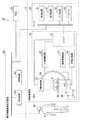
図8は、第2の実施形態に係る医用画像診断システム1Bの一例を示す概念的な構成図である。図8に示すように、医用画像診断システム1Bは、X線CT装置60を備える。 FIG. 8 is a conceptual configuration diagram showing an example of the medical
X線CT装置60は、スキャナ70及びコンソール80を備える。スキャナ70は、検査室に設置され、例えば、被検体PのX線の投影データを収集する。一方、コンソール80は、検査室に隣接する制御室に設置され、投影データから再構成画像を生成する。 The
X線CT装置60は、1回(又は半回転+α)の回転撮像で被検体Pの3次元領域のスキャンを実行することができる。このスキャンは、ボリュームスキャンと呼ばれ、ボリュームスキャンでは3次元画像データ(ボリュームデータ)を収集できる。 The
スキャナ70は、コントローラ71、回転制御回路72、寝台制御回路73、高電圧電源74、及び回転架台76を備える。 The
コントローラ71は、不図示のCPU(Central Processing Unit)などのプロセッサ及びメモリなどを備える。コントローラ71は、回転制御回路72、寝台制御回路73、及び高電圧電源74を制御し撮像動作を統括する。コントローラ71は、回転制御回路72、寝台制御回路73、及び高電圧電源74を夫々制御することにより、回転架台76を回転させつつ、被検体Pが載置された天板78をz軸方向に進退させるヘリカルスキャンを実行する。 The
また、コントローラ71は、回転制御回路72及び寝台制御回路73を介して、X線検出器75、回転架台76、X線管77、天板78、及び寝台79などのスキャナ70を構成する各装置の配置状態を制御する。更に、コントローラ71は、スキャナ70を構成する各装置の撮像時におけるモダリティ座標を記憶する。 Further, the
ここでは一例としてX線CT装置60のモダリティ座標系のx軸、y軸、z軸を以下のように定義する。即ち、鉛直方向をy軸方向とし、y軸方向に垂直であって、天板78の長軸方向に平行な方向をz軸方向とし、これらy軸方向及びz軸方向に垂直な方向をx軸方向とする。 Here, as an example, the x-axis, y-axis, and z-axis of the modality coordinate system of the
回転制御回路72は、コントローラ71の制御の下、回転架台76を不図示の固定架台に対して回転させる。 The
寝台制御回路73は、コントローラ71の制御の下、天板78及び寝台79を移動させる。 The
高電圧電源74は、コントローラ71の制御の下、X線の照射に必要な電力をX線管77に供給する。 The high-
回転架台76は、開口部を有する。また、回転架台76は、X線検出器75やX線管77を一体として保持し、X線検出器75とX線管77とを対向させた状態で開口部内に存在する被検体Pの周りを一体的に回転させる。 The
X線管77は、高電圧電源74から供給された管電圧に応じて金属製のターゲットに電子線を衝突させることでX線を発生させ、X線をX線検出器75に向かって照射する。X線管77から照射されるX線によって、ファンビームX線やコーンビームX線が形成される。 The
X線検出器75は、X線管77から照射されたX線を検出する検出素子を複数備える。X線検出器75は、例えば、多数の検出素子をチャネル方向及び列方向に沿ってマトリクス状に配列した2次元アレイ型の検出器である。2次元アレイ型の検出器は、マルチスライス型検出器とも呼ばれる。 The
寝台79は、床面に設置され天板78を支持する。天板78は、コントローラ71の制御の下、鉛直方向であるy軸に垂直なxz面内方向を水平移動し、y軸方向に上下移動する。 The
コンソール80は、コントローラ71から入力された投影データを再構成してCT画像を生成する。スキャナ70で収集された投影データがボリュームデータの場合、コンソール80は、3次元画像データを再構成する。コンソール80は、処理回路81、記憶回路82、入力回路83、及びディスプレイ84を備える。なお、処理回路81、記憶回路82、入力回路83、及びディスプレイ84のハードウェア構成は、第1の実施形態のコンソール30の処理回路31、記憶回路32、入力回路33、及びディスプレイ34と同様でよいので詳細な説明を省略する。 The
第2の実施形態に係る医用画像診断システム1Bは、第1の実施形態の場合と同様の方法で複合現実画像を生成する。第1の実施形態において、処理回路41a(のROI位置特定機能411a)は、2つのX線画像に設定されたROIに基づいて、モダリティ座標系におけるROIの3次元位置を特定した。第2の実施形態では、X線CT装置60で収集されるCT画像が3次元画像データであるため、CT画像からROIの3次元位置が特定される。 The medical
CT画像の場合、ROIは、例えば、スライス画像(断層像)上で設定される。X線CT装置60の撮像条件としてスライス厚が設定されており、ROIが設定されたスライス画像のスライス番号に基づいて3次元画像データ上のROIの位置を特定できる。3次元画像データ上のROIの位置は、例えば、3次元画像データのボクセルとして特定される。 In the case of CT images, the ROI is set, for example, on a slice image (tomographic image). The slice thickness is set as an imaging condition of the
また、X線CT装置60にもモダリティ座標系が規定されており、処理回路41a(のROI位置特定機能411a)は、CT画像撮像時の回転架台76の位置や天板78の位置などのスキャナ70を構成する各装置の配置状態に基づいて、モダリティ座標系におけるROIの3次元位置を特定できる。 Further, the modality coordinate system is also defined in the
例えば、天板78及び回転架台76の位置から被検体Pのモダリティ座標系における撮像開始位置が特定される。ROIが設定されたスライス画像のスライス番号とスライス厚とから、撮像開始位置からROIが設定されたスライス画像までの距離が特定できる。 For example, the imaging start position of the subject P in the modality coordinate system is specified from the positions of the
図9は、第2の実施形態に係る複合現実画像の表示例を示す模式図である。図9の複合現実画像IMG5は、図6の上段の複合現実画像IMG2に示された被検体Pの体内にあるROIの位置を、ユーザQが同じ位置及び同じ方向から観察した場合を示している。複合現実画像IMG5は、ROIの表示のみ複合現実画像IMG2と異なる。 FIG. 9 is a schematic view showing a display example of a mixed reality image according to the second embodiment. The mixed reality image IMG5 of FIG. 9 shows a case where the user Q observes the position of the ROI in the body of the subject P shown in the mixed reality image IMG2 in the upper part of FIG. 6 from the same position and the same direction. .. The mixed reality image IMG5 differs from the mixed reality image IMG2 only in the display of the ROI.
複合現実画像IMG4には、ROIの中心位置CRに加えて、ROIを含む心臓HERの画像が表示される。処理回路41a(の複合現実画像生成機能414a)は、第1の実施形態と同様にして、複合現実画像IMG4のようにCT画像上で設定されたROIの周辺画像をカメラ画像に重畳してもよい。処理回路41a(の複合現実画像生成機能414a)は、例えば、複合現実画像表示装置50の位置及び姿勢に合わせてROIの周辺の画像を回転させてカメラ画像に重畳することで、複合現実画像を生成してもよい。 In the mixed reality image IMG4, an image of the heart HER including the ROI is displayed in addition to the center position CR of the ROI. The
図9では、心臓HERの表面に存在する冠動脈血管にROIの中心位置CRが設定される場合を示したが、ROIは、臓器の内部に存在する場合もある。ROIが臓器の内部に位置する場合、処理回路41a(の複合現実画像生成機能414a)は、ROI内の臓器が所定の透過度で重畳された複合現実画像を生成してもよい。 FIG. 9 shows a case where the central position CR of the ROI is set in the coronary artery blood vessel existing on the surface of the heart HER, but the ROI may be present inside the organ. When the ROI is located inside an organ, the
また、処理回路41a(の複合現実画像生成機能414a)は、例えば、腫瘍や動脈瘤などの治療対象部位の3次元的な形状をカメラ画像に重畳することで、複合現実画像を生成してもよい。例えば、腫瘍や動脈瘤などの治療対象部位は、CT画像において立体的な形状で特定される。処理回路41a(の複合現実画像生成機能414a)は、特定された立体的な形状を、例えば、所定の透過度で被検体Pのカメラ画像に重畳し、複合現実画像を生成してもよい。 Further, the
複合現実画像には、複合現実画像表示装置50の位置及び姿勢に応じて腫瘍や動脈瘤などの治療対象部位の立体的な形状が表示される。そのため、治療対象部位が血管や他の臓器や組織の後ろに存在し、実際に見えない位置にある場合でも、ユーザQは、複合現実画像により治療対象部位の立体的形状を視覚的に認識することができる。 In the mixed reality image, the three-dimensional shape of the treatment target site such as a tumor or an aneurysm is displayed according to the position and posture of the mixed reality
このように、第2の実施形態においても、第1の実施形態と同様の効果が得られる。更に、第2の実施形態では、ROIやROIの周辺にある臓器の立体的な形状が複合現実画像上に描出されることで、ユーザは、ROIとROIを含む臓器との位置関係から適切な切開位置を特定することができる。 As described above, the same effect as that of the first embodiment can be obtained in the second embodiment. Further, in the second embodiment, the three-dimensional shape of the ROI and the organs around the ROI is drawn on the mixed reality image, so that the user can appropriately consider the positional relationship between the ROI and the organ including the ROI. The incision position can be specified.
[第3の実施形態]
第1の実施形態及び第2の実施形態では、医用画像診断システムで撮像された医用画像にROIを設定し、当該ROIの位置をカメラ画像に重畳した複合現実画像の例を説明したが、複合現実画像上でのROIの位置の示し方は、この態様には限定されない。例えば、医用画像診断システムは、医用画像診断システム以外で撮像された医用画像に設定されたROIを利用して複合現実画像を生成してもよい。[Third Embodiment]
In the first embodiment and the second embodiment, an example of a mixed reality image in which an ROI is set in a medical image captured by a medical image diagnosis system and the position of the ROI is superimposed on a camera image has been described. The method of indicating the position of the ROI on the real image is not limited to this aspect. For example, the medical image diagnosis system may generate a mixed reality image by using the ROI set in the medical image captured by a medical image diagnosis system other than the medical image diagnosis system.
第3の実施形態では、医用画像診断システムで撮像された医用画像と、医用画像診断システム以外の他の装置で撮像され、ROIが設定された医用画像とを位置合わせし、ROIの位置を複合現実画像上に表示する医用画像診断システム1Cの例を説明する。なお、第1の実施形態と同様の構成については同一の符号を付し、重複する説明を省略する。 In the third embodiment, the medical image captured by the medical image diagnosis system and the medical image captured by a device other than the medical image diagnosis system and the ROI is set are aligned, and the position of the ROI is combined. An example of the medical image diagnosis system 1C displayed on a real image will be described. The same components as those in the first embodiment are designated by the same reference numerals, and duplicate description will be omitted.
(1)構成
図10は、第3の実施形態に係る医用画像診断システム1Cの一例を示す概念的な構成図である。図10に示すように、医用画像診断システム1Cは、第1の実施形態の医用画像診断システム1Aの構成に加えて、画像保管通信システム(Picture Archiving and Communication Systems:以下、PACSと略記する)90を更に備える。(1) Configuration FIG. 10 is a conceptual configuration diagram showing an example of the medical image diagnosis system 1C according to the third embodiment. As shown in FIG. 10, the medical image diagnosis system 1C includes a picture archiving and communication system (hereinafter abbreviated as PACS) 90 in addition to the configuration of the medical
PACS90は、モダリティにより得られた画像データを蓄積し、表示装置などの参照端末からの要求に応じて画像データを参照端末に送信するシステムである。PACS90には、過去に撮像された被検体Pの医用画像が保存されている。 The
PACS90は、複合現実画像生成装置40cに、例えば、電子ネットワーク経由で接続され、複合現実画像生成装置40cの要求に応じて画像データを送信する。 The
ここで、電子ネットワークとは、電気通信技術を利用した情報通信網全体を意味し、病院基幹LAN、無線/有線LANやインターネット網の他、電話通信回線網、光ファイバー通信ネットワーク、ケーブル通信ネットワーク、及び衛星通信ネットワークなどを含む。 Here, the electronic network means the entire information communication network using telecommunications technology, and in addition to the hospital backbone LAN, wireless / wired LAN, and Internet network, telephone communication line network, optical fiber communication network, cable communication network, and so on. Includes satellite communication networks, etc.
図11は、第3実施形態に係る医用画像診断システム1Cの機能構成例を示す機能ブロック図である。 FIG. 11 is a functional block diagram showing a functional configuration example of the medical image diagnosis system 1C according to the third embodiment.
複合現実画像生成装置40cの処理回路41cは、位置合わせ機能415cを実現する。位置合わせ機能415cは、記憶回路42に格納されているプログラムを処理回路41cのプロセッサが実行することによって実現される機能である。 The
位置合わせ機能415cは、X線診断装置10のコンソール30から被検体PのX線画像を取得する。また、位置合わせ機能415cは、PACS90から被検体PのROI設定済みの医用画像を取得する。位置合わせ機能415cは、PACS90から被検体Pの画像診断や手術計画に利用された医用画像を取得する。画像診断や手術計画に利用された医用画像は、ROIが設定済みの3次元画像である。 The
被検体PのX線画像は、被検体Pを少なくとも1方向から撮像した画像データである。位置合わせ機能415cは、X線画像とROI設定済みの医用画像とを位置合わせする。位置合わせは、例えば、パターンマッチングなどの画像処理により行われる。また、位置合わせの目印となるアルミなどの人工物を被検体Pに付着させた状態で、夫々の医用画像の撮像を行い、当該人工物に基づいて位置合わせを行ってもよい。 The X-ray image of the subject P is image data obtained by capturing the subject P from at least one direction. The
更に、ROIが設定済みの3次元画像は、被検体Pの撮像時の体位及び天板28からROIの位置までの垂直方向の距離に関する情報項目を含んでもよい。医用画像診断システム1Cは、ROIが設定済みの3次元画像に含まれる体位から、天板28とROIの位置とを結ぶ方向をモダリティ座標系の1つの軸方向に一致させてX線画像を撮像してもよい。 Further, the three-dimensional image in which the ROI has been set may include information items regarding the body position of the subject P at the time of imaging and the vertical distance from the
例えば、医用画像診断システム1C以外のモダリティにおいて、天板に対して仰臥位で載置された被検体Pを撮像した場合、医用画像診断システム1Cにおいても、被検体Pを天板28に対して仰臥位で載置してX線画像を撮像する。この場合、天板28とROIの位置とを結ぶ直線はy軸方向に一致するため、X線管27とX線検出器25とを結ぶ直線をy軸方向に一致させ、xz平面の画像を撮像する。これにより、1方向からのX線画像を取得するだけでよく、被曝量を低減できる。 For example, when a subject P placed in a supine position with respect to a top plate is imaged in a modality other than the medical image diagnosis system 1C, the subject P is also mounted on the
なお、X線画像とROI設定済みの医用画像との位置合わせは、従来技術と同様で良いため、詳細な説明を省略する。 Since the alignment between the X-ray image and the medical image for which the ROI has been set may be the same as in the prior art, detailed description thereof will be omitted.
(2)動作
図12は、第3の実施形態に係る医用画像診断システムの動作の一例を示すフローチャートである。以下、図12のフローチャートのステップ番号に従って、第3の実施形態に係る医用画像診断システム1Cの動作について説明する。なお、図3のフローチャートと同一の処理には同一の符号を付し、説明を省略する。(2) Operation FIG. 12 is a flowchart showing an example of the operation of the medical image diagnosis system according to the third embodiment. Hereinafter, the operation of the medical image diagnosis system 1C according to the third embodiment will be described according to the step numbers in the flowchart of FIG. The same processes as those in the flowchart of FIG. 3 are designated by the same reference numerals, and the description thereof will be omitted.
ステップST201において、X線診断装置10は、天板28に載置された被検体Pを所定の方向から撮像し、X線画像を取得する。 In step ST201, the X-ray
ステップST202において、位置合わせ機能415cは、PACS90からROI設定済みの医用画像を取得する。 In step ST202, the
ステップST203において、位置合わせ機能415cは、X線画像とROI設定済みの医用画像とを位置合わせする。ROI位置特定機能411aは、X線画像とROI設定済みの医用画像とが位置合わせされた画像からROIの3次元位置を特定する。 In step ST203, the
ステップST104〜ST107における各処理により、ステップST204で特定されたROIの3次元位置をカメラ画像に重畳した複合現実画像が生成され、複合現実画像表示装置50に表示される。 By each process in steps ST104 to ST107, a mixed reality image in which the three-dimensional position of the ROI specified in step ST204 is superimposed on the camera image is generated and displayed on the mixed reality
このように第3の実施形態においても、第1の実施形態と同様の効果が得られる。更に、第3の実施形態では、診断時に設定されたROIを利用するため、医用画像診断システム1Cで取得したX線画像にROIを設定する処理を省略できる。また、PET(Positron Emission Tomography)装置などの被検体の機能異常を画像化することで病巣を特定するモダリティで取得された医用画像を利用することもできる。 As described above, the same effect as that of the first embodiment can be obtained in the third embodiment. Further, in the third embodiment, since the ROI set at the time of diagnosis is used, the process of setting the ROI in the X-ray image acquired by the medical image diagnosis system 1C can be omitted. It is also possible to use a medical image acquired by a modality for identifying a lesion by imaging a functional abnormality of a subject such as a PET (Positron Emission Tomography) device.
以上述べた少なくとも一つの実施形態の医用画像診断システム及び複合現実画像生成装置によれば、医用画像上で特定された被検体の治療対象位置を従来とは異なる方法で認識可能となる。 According to the medical image diagnosis system and the mixed reality image generation device of at least one embodiment described above, the treatment target position of the subject specified on the medical image can be recognized by a method different from the conventional method.
なお、請求項の用語と実施形態との対応関係は、例えば以下の通りである。実施形態のX線診断装置10及びX線CT装置60は、請求項記載の撮像部の一例である。また、実施形態のROI位置特定機能411aは、請求項記載の特定部の一例である。また、実施形態の複合現実画像生成機能414aは、請求項記載の処理部の一例である。また、実施形態の位置合わせ機能415cは、請求項記載の位置合わせ部の一例である。 The correspondence between the terms of the claims and the embodiments is as follows, for example. The X-ray
本発明のいくつかの実施形態を説明したが、これらの実施形態は、例として提示したものであり、発明の範囲を限定することは意図していない。これら実施形態は、その他の様々な形態で実施されることが可能であり、発明の要旨を逸脱しない範囲で、種々の省略、置き換え、変更を行うことができる。これら実施形態やその変形は、発明の範囲や要旨に含まれると同様に、特許請求の範囲に記載された発明とその均等の範囲に含まれるものである。 Although some embodiments of the present invention have been described, these embodiments are presented as examples and are not intended to limit the scope of the invention. These embodiments can be implemented in various other forms, and various omissions, replacements, and changes can be made without departing from the gist of the invention. These embodiments and modifications thereof are included in the scope and gist of the invention, as well as in the scope of the invention described in the claims and the equivalent scope thereof.
1A、1B、1C…医用画像診断システム
40a、40c…複合現実画像生成装置
50…複合現実画像表示装置1A, 1B, 1C ... Medical
Claims (12)
Translated fromJapaneseディスプレイ及び位置姿勢センサを有し、前記ディスプレイがユーザの視野に含まれるように前記ユーザの頭部に対して装着される表示部と、
前記撮像部により生成された前記X線画像に対して設定された関心領域の位置と、前記X線画像の生成時の前記照射機構及び前記検出器の配置状態とに応じて、前記撮像部の設置室における前記関心領域の実際の3次元位置を特定する特定部と、
前記位置姿勢センサによって検出される前記表示部の位置及び姿勢を前記表示部からリアルタイムで順次取得し、前記設置室における前記表示部の位置及び姿勢と、前記設置室における前記関心領域の実際の3次元位置とに応じて、前記ディスプレイと前記関心領域との位置関係に整合するように、前記設置室における前記関心領域の実際の3次元位置を前記ディスプレイ上で示す画像データを順次生成し、前記画像データを前記表示部に順次送信する処理部と、
を備える医用画像診断システム。An imaging unit that generates an X-ray image of the subject by detecting the X-rays that have been irradiated from the irradiation mechanism and passed through the subject with a detector.
A display unit having a display and a position / orientation sensor, which is attached to the user's head so that the display is included in the user's field of view.
Depending on the position of the region of interest set for the X-ray image generated by the imaging unit and the arrangement state of the irradiation mechanism and the detector at the time of generation of the X-ray image, the imaging unitA specific part that identifies the actual three-dimensional position of the region of interest in the installation room, and
The position and orientation of the display unit detected by the position / orientation sensor are sequentially acquired from the display unit in real time, and the position and orientation of the display unit in theinstallation room andthe actual 3 of the area of interestin the installation room are obtained.Image data indicating the actual three-dimensional position of the area of interestin the installation room on the display is sequentially generated so as to match the positional relationship between the display and the area of interest according to the dimensional position. A processing unit that sequentially transmits image data to the display unit, and
Medical diagnostic imaging system equipped with.
前記処理部は、前記カメラ画像を前記表示部から順次取得し、前記位置姿勢センサによって検出される前記表示部の位置及び姿勢に基づいて、前記設置室における前記関心領域の実際の3次元位置が前記カメラ画像に重畳された前記画像データを順次生成する、
請求項1に記載の医用画像診断システム。The display unit further includes a camera that sequentially generates camera images by capturing an image of the front region of the display, which is opposite to both eyes of the user with respect to the display.
The processing unit sequentially acquires the camera images from the display unit, and based on the position and orientation of the display unit detected by the position / orientation sensor,the actual three-dimensional position of the area of interestin the installation room is determined. The image data superimposed on the camera image is sequentially generated.
The medical diagnostic imaging system according to claim 1.
請求項1又は請求項2に記載の医用画像診断システム。The processing unit generates the image data in which the position in the depth direction ofthe actual three-dimensional position of the region of interestin the installation room is depicted by the parallax effect.
The medical diagnostic imaging system according to claim 1 or 2.
前記特定部は、同一の前記被検体の同一領域が含まれるように前記X線管からのX線照射角度が互いに異なる少なくとも2つのX線画像に対して夫々設定された関心領域から、前記設置室における前記関心領域の実際の3次元位置を特定する、
請求項1乃至3のいずれか1項に記載の医用画像診断システム。The imaging unit has an X-ray tube as the irradiation mechanism.
The specific portion is installed from a region of interest set for at least two X-ray images having different X-ray irradiation angles from the X-ray tube so as to include the same region of the same subject.Identifying the actual three-dimensional position of the region of interest in thechamber,
The medical diagnostic imaging system according to any one of claims 1 to 3.
請求項4に記載の医用画像診断システム。The identification unit identifies the actual three-dimensional position of the region of interestin the installation room based on the intersection of each straight line connecting the X-ray tube and the region of interest set in the two X-ray images. ,
The medical diagnostic imaging system according to claim 4.
前記特定部は、前記位置合わせ部により位置合わせされた画像に基づいて前記設置室における前記関心領域の実際の3次元位置を特定する、
請求項1乃至3のいずれか1項に記載の医用画像診断システム。Further comprising an alignment section for aligning at least one of the X-ray images with a three-dimensional medical image generated by another device and set with a region of interest.
The identification unit identifies the actual three-dimensional position of the region of interestin the installation room based on the image aligned by the alignment unit.
The medical diagnostic imaging system according to any one of claims 1 to 3.
請求項6に記載の医用画像診断システム。The specific portion is based on the distance in the direction perpendicular to the top plate from the top plate on which the subject is placed at the time of capturing the three-dimensional medical image to the region of interest set in the three-dimensional medical image. Identifying the actual three-dimensional position of the region of interest in theinstallation room in the X-ray image.
The medical diagnostic imaging system according to claim 6.
請求項2乃至7のいずれか1項に記載の医用画像診断システム。The processing unit sequentially generates image data of a symbol image having a predetermined shape indicating the center position of the region of interest or the range of the region of interest as the image data.
The medical diagnostic imaging system according to any one of claims 2 to 7.
請求項2乃至7のいずれか1項に記載の医用画像診断システム。The processing unit extracts an image within the range of the region of interest or an image of the periphery including the region of interest from the X-ray image, and the extracted image and an image indicating the position of the region of interest are superimposed. Generate image data,
The medical diagnostic imaging system according to any one of claims 2 to 7.
請求項1乃至9のいずれか1項に記載の医用画像診断システム。The imaging unit includes an X-ray tube as a part of the irradiation mechanism and the detector with respect to one end side and the other end side of the C arm that can rotate around the top plate on which the subject is placed. Is configured as an X-ray diagnostic device provided with each
The medical diagnostic imaging system according to any one of claims 1 to 9.
請求項1乃至9のいずれか1項に記載の医用画像診断システム。The imaging unit is arranged such that an X-ray tube as a part of the irradiation mechanism and the detector face each other in a gantry that can rotate around a top plate on which the subject is placed. Configured as a line CT device,
The medical diagnostic imaging system according to any one of claims 1 to 9.
前記X線画像に対して設定された関心領域の位置と、前記X線画像の生成時の前記照射機構及び前記検出器の配置状態とを前記撮像装置から取得し、前記関心領域の位置と、前記配置状態とに応じて、前記撮像装置の設置室における前記関心領域の実際の3次元位置を特定する特定部と、
前記ヘッドマウントディスプレイに内蔵された位置姿勢センサによって検出される前記ヘッドマウントディスプレイの位置及び姿勢を前記ヘッドマウントディスプレイから順次取得し、前記設置室における前記ヘッドマウントディスプレイの位置及び姿勢と、前記設置室における前記関心領域の実際の3次元位置とに応じて、前記ヘッドマウントディスプレイと前記関心領域との位置関係に整合するように、前記設置室における前記関心領域の実際の3次元位置を前記ヘッドマウントディスプレイの画面上で示す位置情報データを順次生成し、前記位置情報データを前記ヘッドマウントディスプレイに順次送信する処理部と、
を備える複合現実画像生成装置。Communication with an imaging device that generates an X-ray image of the subject by detecting X-rays that have been irradiated from the irradiation mechanism and transmitted through the subject with a detector, and with a head-mounted display that is worn on the user's head. A mixed reality image generator that executes communication
The position of the region of interest set with respect to the X-ray image and the arrangement state of the irradiation mechanism and the detector at the time of generating the X-ray image are acquired from the image pickup apparatus, and the position of the region of interest and the position of the region of interest are obtained.A specific unit that specifies the actual three-dimensional position of the region of interest in the installation room of the imaging device according to the arrangement state, and
The head-mounted display sequentially acquires the position and orientation of the head mounted display is detected by the built-in position and orientation sensor from the head-mounted display, the position and orientation of the head mounted displayin the installation room,the installation chamber Theactualthree-dimensional position of the area of interest in the installation room is head-mounted so as to match the positional relationship between the head-mounted display and the area of interest according to theactual three-dimensional position of the area of interest in. A processing unit that sequentially generates position information data shown on the screen of the display and sequentially transmits the position information data to the head-mounted display.
A mixed reality image generator.
Priority Applications (1)
| Application Number | Priority Date | Filing Date | Title |
|---|---|---|---|
| JP2017020315AJP6878028B2 (en) | 2017-02-07 | 2017-02-07 | Medical image diagnostic system and mixed reality image generator |
Applications Claiming Priority (1)
| Application Number | Priority Date | Filing Date | Title |
|---|---|---|---|
| JP2017020315AJP6878028B2 (en) | 2017-02-07 | 2017-02-07 | Medical image diagnostic system and mixed reality image generator |
Publications (2)
| Publication Number | Publication Date |
|---|---|
| JP2018126251A JP2018126251A (en) | 2018-08-16 |
| JP6878028B2true JP6878028B2 (en) | 2021-05-26 |
Family
ID=63172578
Family Applications (1)
| Application Number | Title | Priority Date | Filing Date |
|---|---|---|---|
| JP2017020315AActiveJP6878028B2 (en) | 2017-02-07 | 2017-02-07 | Medical image diagnostic system and mixed reality image generator |
Country Status (1)
| Country | Link |
|---|---|
| JP (1) | JP6878028B2 (en) |
Families Citing this family (4)
| Publication number | Priority date | Publication date | Assignee | Title |
|---|---|---|---|---|
| WO2020041615A1 (en)* | 2018-08-22 | 2020-02-27 | Magic Leap, Inc. | Patient viewing system |
| CN109674532A (en)* | 2019-01-25 | 2019-04-26 | 上海交通大学医学院附属第九人民医院 | Operation guiding system and its equipment, method and storage medium based on MR |
| EP3725231B1 (en)* | 2019-04-17 | 2021-07-21 | Sirona Dental Systems GmbH | Apparatus for real-time visualizing a movement of a lower jaw versus an upper jaw in a craniomaxillofacial area of a patient in dental diagnostics |
| JP7563324B2 (en)* | 2021-07-29 | 2024-10-08 | 株式会社島津製作所 | X-ray imaging device |
Family Cites Families (5)
| Publication number | Priority date | Publication date | Assignee | Title |
|---|---|---|---|---|
| JP2000084096A (en)* | 1998-09-14 | 2000-03-28 | Sumitomo Heavy Ind Ltd | Positioning method and device |
| US20040254454A1 (en)* | 2001-06-13 | 2004-12-16 | Kockro Ralf Alfons | Guide system and a probe therefor |
| JP5335201B2 (en)* | 2007-05-08 | 2013-11-06 | キヤノン株式会社 | Diagnostic imaging equipment |
| JP6437286B2 (en)* | 2014-11-26 | 2018-12-12 | 株式会社東芝 | Image processing apparatus, image processing program, image processing method, and treatment system |
| JP6687393B2 (en)* | 2015-04-14 | 2020-04-22 | キヤノンメディカルシステムズ株式会社 | Medical image diagnostic equipment |
- 2017
- 2017-02-07JPJP2017020315Apatent/JP6878028B2/enactiveActive
Also Published As
| Publication number | Publication date |
|---|---|
| JP2018126251A (en) | 2018-08-16 |
Similar Documents
| Publication | Publication Date | Title |
|---|---|---|
| JP7051307B2 (en) | Medical image diagnostic equipment | |
| KR101572487B1 (en) | System and Method For Non-Invasive Patient-Image Registration | |
| CN104244831B (en) | Medical X-ray Devices | |
| ES2674433T3 (en) | Analysis of corresponding radiographs | |
| JP7181298B2 (en) | Systems and methods for detecting abnormal tissue using vascular features | |
| KR101458585B1 (en) | Radiopaque Hemisphere Shape Maker for Cardiovascular Diagnosis and Procedure Guiding Image Real Time Registration | |
| IL293233A (en) | Image registration with a tracking system | |
| US20120293511A1 (en) | Method for displaying an area to be medically examined and/or treated | |
| JP2003290192A (en) | Image delineation method of medical instruments introduced to patient's examination area | |
| JP2003305032A (en) | Method for detecting and rendering a medical catheter introduced in an examination area of a patient | |
| CN110584782B (en) | Medical image processing method, medical image processing apparatus, medical system, computer, and storage medium | |
| JP6349278B2 (en) | Radiation imaging apparatus, image processing method, and program | |
| CN117677358A (en) | Augmented reality system and method for stereoscopic projection and cross-referencing of in-situ X-ray fluoroscopy and C-arm computed tomography imaging during surgery | |
| JP6878028B2 (en) | Medical image diagnostic system and mixed reality image generator | |
| JP6809851B2 (en) | Medical image diagnostic equipment and medical image processing equipment | |
| CN114727845A (en) | Method and system for reconstructing a puncture point of a medical instrument | |
| EP3838159A1 (en) | Navigating bronchial pathways | |
| JP5405010B2 (en) | Image display device and image display method | |
| KR101485900B1 (en) | Image matching method between computed tomography angiography image and X-Ray angiography image based on hemisphere shaped radiopaque 3D Marker | |
| US8934604B2 (en) | Image display apparatus and X-ray diagnostic apparatus | |
| US12108993B2 (en) | Methods and system for guided device insertion during medical imaging | |
| JP6918443B2 (en) | Medical information processing device | |
| JP6871007B2 (en) | Medical image processing equipment and medical diagnostic imaging system | |
| JP6824641B2 (en) | X-ray CT device | |
| CN107260305A (en) | Area of computer aided minimally invasive surgery system |
Legal Events
| Date | Code | Title | Description |
|---|---|---|---|
| A621 | Written request for application examination | Free format text:JAPANESE INTERMEDIATE CODE: A621 Effective date:20191210 | |
| A977 | Report on retrieval | Free format text:JAPANESE INTERMEDIATE CODE: A971007 Effective date:20201026 | |
| A131 | Notification of reasons for refusal | Free format text:JAPANESE INTERMEDIATE CODE: A131 Effective date:20201110 | |
| A521 | Request for written amendment filed | Free format text:JAPANESE INTERMEDIATE CODE: A523 Effective date:20210112 | |
| TRDD | Decision of grant or rejection written | ||
| A01 | Written decision to grant a patent or to grant a registration (utility model) | Free format text:JAPANESE INTERMEDIATE CODE: A01 Effective date:20210406 | |
| A61 | First payment of annual fees (during grant procedure) | Free format text:JAPANESE INTERMEDIATE CODE: A61 Effective date:20210428 | |
| R150 | Certificate of patent or registration of utility model | Ref document number:6878028 Country of ref document:JP Free format text:JAPANESE INTERMEDIATE CODE: R150 |