JP6877491B2 - Systems and methods for adjusting the proximal tibia - Google Patents
Systems and methods for adjusting the proximal tibiaDownload PDFInfo
- Publication number
- JP6877491B2 JP6877491B2JP2019123347AJP2019123347AJP6877491B2JP 6877491 B2JP6877491 B2JP 6877491B2JP 2019123347 AJP2019123347 AJP 2019123347AJP 2019123347 AJP2019123347 AJP 2019123347AJP 6877491 B2JP6877491 B2JP 6877491B2
- Authority
- JP
- Japan
- Prior art keywords
- cutting
- surgical
- tool
- bone
- boundary surface
- Prior art date
- Legal status (The legal status is an assumption and is not a legal conclusion. Google has not performed a legal analysis and makes no representation as to the accuracy of the status listed.)
- Active
Links
- 238000000034methodMethods0.000titleclaimsdescription90
- 210000002303tibiaAnatomy0.000titledescription65
- 238000005520cutting processMethods0.000claimsdescription116
- 239000007943implantSubstances0.000claimsdescription60
- 210000000988bone and boneAnatomy0.000claimsdescription41
- 238000001356surgical procedureMethods0.000claimsdescription26
- 230000008569processEffects0.000claimsdescription25
- 230000033001locomotionEffects0.000claimsdescription18
- 230000008713feedback mechanismEffects0.000claimsdescription17
- 210000003484anatomyAnatomy0.000description22
- 210000003041ligamentAnatomy0.000description21
- 210000000629knee jointAnatomy0.000description19
- 210000000689upper legAnatomy0.000description17
- 210000001519tissueAnatomy0.000description13
- 230000006870functionEffects0.000description9
- 239000003550markerSubstances0.000description9
- 238000001514detection methodMethods0.000description8
- 238000004891communicationMethods0.000description7
- 238000003780insertionMethods0.000description7
- 230000037431insertionEffects0.000description7
- 238000004590computer programMethods0.000description6
- 210000003127kneeAnatomy0.000description6
- 238000013150knee replacementMethods0.000description6
- 230000003287optical effectEffects0.000description6
- 210000001264anterior cruciate ligamentAnatomy0.000description5
- 238000007796conventional methodMethods0.000description5
- 238000012545processingMethods0.000description5
- 230000000007visual effectEffects0.000description5
- 230000006378damageEffects0.000description4
- 229910052751metalInorganic materials0.000description4
- 239000002184metalSubstances0.000description4
- 238000012986modificationMethods0.000description4
- 230000004048modificationEffects0.000description4
- 230000000399orthopedic effectEffects0.000description4
- 230000009466transformationEffects0.000description4
- 238000011426transformation methodMethods0.000description4
- 229910001069Ti alloyInorganic materials0.000description3
- RTAQQCXQSZGOHL-UHFFFAOYSA-NTitaniumChemical compound[Ti]RTAQQCXQSZGOHL-UHFFFAOYSA-N0.000description3
- 208000027418Wounds and injuryDiseases0.000description3
- 210000000845cartilageAnatomy0.000description3
- 238000003384imaging methodMethods0.000description3
- 208000014674injuryDiseases0.000description3
- 230000001902propagating effectEffects0.000description3
- 238000013515scriptMethods0.000description3
- 239000010936titaniumSubstances0.000description3
- 229910000831SteelInorganic materials0.000description2
- 229910001093Zr alloyInorganic materials0.000description2
- WAIPAZQMEIHHTJ-UHFFFAOYSA-N[Cr].[Co]Chemical class[Cr].[Co]WAIPAZQMEIHHTJ-UHFFFAOYSA-N0.000description2
- 239000000853adhesiveSubstances0.000description2
- 230000001070adhesive effectEffects0.000description2
- 239000000956alloySubstances0.000description2
- 230000005540biological transmissionEffects0.000description2
- 230000008859changeEffects0.000description2
- 239000000788chromium alloySubstances0.000description2
- 230000004064dysfunctionEffects0.000description2
- 230000000694effectsEffects0.000description2
- 230000003993interactionEffects0.000description2
- 230000007246mechanismEffects0.000description2
- 230000005499meniscusEffects0.000description2
- 229910001092metal group alloyInorganic materials0.000description2
- 230000003278mimic effectEffects0.000description2
- 229920001610polycaprolactonePolymers0.000description2
- 210000002967posterior cruciate ligamentAnatomy0.000description2
- 238000002271resectionMethods0.000description2
- 230000004044responseEffects0.000description2
- 239000000523sampleSubstances0.000description2
- 210000004872soft tissueAnatomy0.000description2
- 239000010959steelSubstances0.000description2
- 229910052715tantalumInorganic materials0.000description2
- GUVRBAGPIYLISA-UHFFFAOYSA-Ntantalum atomChemical compound[Ta]GUVRBAGPIYLISA-UHFFFAOYSA-N0.000description2
- 229910052719titaniumInorganic materials0.000description2
- PXFBZOLANLWPMH-UHFFFAOYSA-N16-EpiaffinineNatural productsC1C(C2=CC=CC=C2N2)=C2C(=O)CC2C(=CC)CN(C)C1C2COPXFBZOLANLWPMH-UHFFFAOYSA-N0.000description1
- 208000006820ArthralgiaDiseases0.000description1
- 208000036487ArthropathiesDiseases0.000description1
- 208000037408Device failureDiseases0.000description1
- 241000567769Isurus oxyrinchusSpecies0.000description1
- 208000003947Knee OsteoarthritisDiseases0.000description1
- 241000699670Mus sp.Species0.000description1
- 208000002193PainDiseases0.000description1
- 238000013459approachMethods0.000description1
- 238000003491arrayMethods0.000description1
- 230000008901benefitEffects0.000description1
- 239000003086colorantSubstances0.000description1
- 230000003750conditioning effectEffects0.000description1
- 238000013461designMethods0.000description1
- 238000010586diagramMethods0.000description1
- 239000012636effectorSubstances0.000description1
- 238000005516engineering processMethods0.000description1
- 239000000835fiberSubstances0.000description1
- 239000011521glassSubstances0.000description1
- 238000002513implantationMethods0.000description1
- 230000002452interceptive effectEffects0.000description1
- 230000008407joint functionEffects0.000description1
- 238000013507mappingMethods0.000description1
- 239000000463materialSubstances0.000description1
- 238000005259measurementMethods0.000description1
- 238000003801millingMethods0.000description1
- 201000008482osteoarthritisDiseases0.000description1
- 210000004417patellaAnatomy0.000description1
- 230000000149penetrating effectEffects0.000description1
- 229920003023plasticPolymers0.000description1
- 239000004033plasticSubstances0.000description1
- 230000002980postoperative effectEffects0.000description1
- 230000009023proprioceptive sensationEffects0.000description1
- 230000008439repair processEffects0.000description1
- 230000000717retained effectEffects0.000description1
- 239000004065semiconductorSubstances0.000description1
- 230000001953sensory effectEffects0.000description1
- 210000000323shoulder jointAnatomy0.000description1
- 238000006467substitution reactionMethods0.000description1
- 238000011883total knee arthroplastyMethods0.000description1
- 238000012546transferMethods0.000description1
- 230000001131transforming effectEffects0.000description1
- 230000001755vocal effectEffects0.000description1
Images


Classifications
- A—HUMAN NECESSITIES
- A61—MEDICAL OR VETERINARY SCIENCE; HYGIENE
- A61B—DIAGNOSIS; SURGERY; IDENTIFICATION
- A61B17/00—Surgical instruments, devices or methods
- A61B17/14—Surgical saws
- A61B17/15—Guides therefor
- A61B17/154—Guides therefor for preparing bone for knee prosthesis
- A61B17/157—Cutting tibia
- A—HUMAN NECESSITIES
- A61—MEDICAL OR VETERINARY SCIENCE; HYGIENE
- A61F—FILTERS IMPLANTABLE INTO BLOOD VESSELS; PROSTHESES; DEVICES PROVIDING PATENCY TO, OR PREVENTING COLLAPSING OF, TUBULAR STRUCTURES OF THE BODY, e.g. STENTS; ORTHOPAEDIC, NURSING OR CONTRACEPTIVE DEVICES; FOMENTATION; TREATMENT OR PROTECTION OF EYES OR EARS; BANDAGES, DRESSINGS OR ABSORBENT PADS; FIRST-AID KITS
- A61F2/00—Filters implantable into blood vessels; Prostheses, i.e. artificial substitutes or replacements for parts of the body; Appliances for connecting them with the body; Devices providing patency to, or preventing collapsing of, tubular structures of the body, e.g. stents
- A61F2/02—Prostheses implantable into the body
- A61F2/30—Joints
- A61F2/46—Special tools for implanting artificial joints
- A61F2/4603—Special tools for implanting artificial joints for insertion or extraction of endoprosthetic joints or of accessories thereof
- A61F2/461—Special tools for implanting artificial joints for insertion or extraction of endoprosthetic joints or of accessories thereof of knees
- A—HUMAN NECESSITIES
- A61—MEDICAL OR VETERINARY SCIENCE; HYGIENE
- A61B—DIAGNOSIS; SURGERY; IDENTIFICATION
- A61B17/00—Surgical instruments, devices or methods
- A61B17/16—Instruments for performing osteoclasis; Drills or chisels for bones; Trepans
- A61B17/1662—Instruments for performing osteoclasis; Drills or chisels for bones; Trepans for particular parts of the body
- A61B17/1675—Instruments for performing osteoclasis; Drills or chisels for bones; Trepans for particular parts of the body for the knee
- A—HUMAN NECESSITIES
- A61—MEDICAL OR VETERINARY SCIENCE; HYGIENE
- A61B—DIAGNOSIS; SURGERY; IDENTIFICATION
- A61B17/00—Surgical instruments, devices or methods
- A61B17/16—Instruments for performing osteoclasis; Drills or chisels for bones; Trepans
- A61B17/17—Guides or aligning means for drills, mills, pins or wires
- A61B17/1739—Guides or aligning means for drills, mills, pins or wires specially adapted for particular parts of the body
- A61B17/1764—Guides or aligning means for drills, mills, pins or wires specially adapted for particular parts of the body for the knee
- A—HUMAN NECESSITIES
- A61—MEDICAL OR VETERINARY SCIENCE; HYGIENE
- A61B—DIAGNOSIS; SURGERY; IDENTIFICATION
- A61B34/00—Computer-aided surgery; Manipulators or robots specially adapted for use in surgery
- A61B34/30—Surgical robots
- A—HUMAN NECESSITIES
- A61—MEDICAL OR VETERINARY SCIENCE; HYGIENE
- A61F—FILTERS IMPLANTABLE INTO BLOOD VESSELS; PROSTHESES; DEVICES PROVIDING PATENCY TO, OR PREVENTING COLLAPSING OF, TUBULAR STRUCTURES OF THE BODY, e.g. STENTS; ORTHOPAEDIC, NURSING OR CONTRACEPTIVE DEVICES; FOMENTATION; TREATMENT OR PROTECTION OF EYES OR EARS; BANDAGES, DRESSINGS OR ABSORBENT PADS; FIRST-AID KITS
- A61F2/00—Filters implantable into blood vessels; Prostheses, i.e. artificial substitutes or replacements for parts of the body; Appliances for connecting them with the body; Devices providing patency to, or preventing collapsing of, tubular structures of the body, e.g. stents
- A61F2/50—Prostheses not implantable in the body
- A61F2/68—Operating or control means
- A61F2002/6827—Feedback system for providing user sensation, e.g. by force, contact or position
Landscapes
- Health & Medical Sciences (AREA)
- Life Sciences & Earth Sciences (AREA)
- Surgery (AREA)
- Engineering & Computer Science (AREA)
- Orthopedic Medicine & Surgery (AREA)
- Veterinary Medicine (AREA)
- Animal Behavior & Ethology (AREA)
- Biomedical Technology (AREA)
- Heart & Thoracic Surgery (AREA)
- Public Health (AREA)
- General Health & Medical Sciences (AREA)
- Oral & Maxillofacial Surgery (AREA)
- Medical Informatics (AREA)
- Molecular Biology (AREA)
- Nuclear Medicine, Radiotherapy & Molecular Imaging (AREA)
- Transplantation (AREA)
- Dentistry (AREA)
- Physical Education & Sports Medicine (AREA)
- Cardiology (AREA)
- Vascular Medicine (AREA)
- Robotics (AREA)
- Surgical Instruments (AREA)
- Prostheses (AREA)
Description
Translated fromJapanese関連出願の相互参照
本願は、2013年12月31日に出願された米国仮特許出願第61/922,723号の恩典および優先権を主張するものであり、その開示内容は、参照により全体として本明細書に組み入れられる。Cross-reference to related applications This application claims the benefits and priority of US Provisional Patent Application No. 61 / 922,723 filed on December 31, 2013, the disclosure of which is hereby incorporated by reference in its entirety. Incorporated into the book.
背景
本開示は、全般的に、骨の切除を実施するためのシステムおよび方法に関し、より具体的には、脛骨プロテーゼインプラント部品を受け入れるように近位脛骨を調整するためのシステムおよび方法に関する。Background The present disclosure relates generally to systems and methods for performing bone resection, and more specifically to systems and methods for adjusting the proximal tibia to accept a tibial prosthesis implant component.
膝関節は、大腿骨の遠位端と脛骨の近位端との間の境界面を含む。適切に機能している膝関節では、大腿骨の内側顆および外側顆は、それぞれの脛骨の内側顆および外側顆に付着している半月板に沿って滑らかに旋回する。膝関節が損傷を受けると、関節を形成する天然の骨および軟骨は、適切に関節接合ができない場合があり、それは、関節痛をもたらす可能性があり、場合によっては、関節の正常な使用を妨げる可能性がある。 The knee joint includes the interface between the distal end of the femur and the proximal end of the tibia. In a properly functioning knee joint, the medial and lateral condyles of the femur swivel smoothly along the meniscus attached to the medial and lateral condyles of the tibia, respectively. When the knee joint is damaged, the natural bone and cartilage that forms the joint may not be able to join properly, which can lead to joint pain and, in some cases, normal use of the joint. May interfere.
状況によっては、関節の正常な使用を回復させ、疼痛を減少するために、手術が必要とされる。損傷の重症度次第で、手術は、関節をプロテーゼ部品で部分的または完全に置き換えることを含み得る。そのような膝置換術の間、外科医は、健常組織を無傷のままにしようと試みながら、骨および軟骨の損傷を受けた部分を切除する。外科医は次に、健常組織に切除された組織を再現するように設計された人工プロテーゼ部品を嵌め込み、適切な膝関節動作を回復させる。 In some situations, surgery is required to restore normal joint use and reduce pain. Depending on the severity of the injury, surgery may involve replacing the joint partially or completely with a prosthesis component. During such knee replacement, the surgeon removes the damaged part of the bone and cartilage while attempting to leave healthy tissue intact. The surgeon then inserts an artificial prosthesis component designed to recreate the resected tissue into healthy tissue to restore proper knee joint movement.
一つの膝置換術−膝関節全置換術(「TKA」)−は、大腿骨および脛骨の両方の内側顆および外側顆の各々のいくつかまたはすべての切除、ならびに大腿脛骨境界面に位置する線維軟骨半月板の除去を含む。典型的にはコバルトクロム合金または他の強固な手術グレードの金属から作られる、プロテーゼ大腿骨部品は、大腿骨の遠位端に嵌め込まれ、固定されて、大腿骨の切除された部分と置き換える。同様に、プロテーゼ脛骨部品(その基部も典型的にはコバルトクロム合金、チタン、または他の適切な金属から作られる)は、脛骨の近位端に嵌め込まれ、固定されて、脛骨の切除された部分と置き換える。 One knee replacement-total knee arthroplasty ("TKA")-is a resection of some or all of the medial and lateral condyles of both the femur and tibia, as well as fibers located at the femoral tibial interface. Includes removal of cartilage meniscus. Prosthesis femoral parts, typically made of cobalt-chromium alloy or other robust surgical grade metal, are fitted and fixed to the distal end of the femur to replace the excised portion of the femur. Similarly, the prosthesis tibial component, whose base is also typically made of cobalt-chromium alloy, titanium, or other suitable metal, was fitted and fixed to the proximal end of the tibia and the tibia was resected. Replace with part.
状況によっては、患者の膝関節の骨が、TKA手術を必要とする段階まで悪化している場合でも、1つまたは複数の患者の十字靭帯(例えば、前十字靭帯(ACL)および/または後十字靭帯(PCL))は、適切な関節安定性を提供するのに十分な状態にある。生得の十字靭帯を維持することは、しばしば有利であり、そうすると一般に固有受容性感覚(身体の何処の部分が互いに関連しているかを感知する能力)に役立つと考えられており、階段を上ることのような活動をより安定または自然に感じさせることもできる。十字靭帯を保存することはまた、より正常な前から後への膝運動を促進することができ、それは術前の可動域を維持する患者の能力を高めることができる(特にそれが深屈曲に関する場合)。靭帯はまた、関節安定性に役立つ。 In some situations, one or more patients' cruciate ligaments (eg, anterior cruciate ligament (ACL) and / or posterior cruciate), even if the patient's knee bone has deteriorated to the point where TKA surgery is required. The ligaments (PCLs) are in sufficient condition to provide adequate joint stability. Maintaining the innate cruciate ligament is often advantageous, and is generally thought to help with proprioceptive sensations (the ability to sense where parts of the body are related to each other) and climb stairs. You can also make activities like this feel more stable or natural. Preserving the cruciate ligament can also promote more normal anterior-posterior knee movement, which can enhance the patient's ability to maintain preoperative range of motion (especially when it comes to deep flexion). If). Ligaments also help with joint stability.
生得の十字靭帯の各々は、大腿顆の1つに結合し、大腿骨の顆間領域内部を通過して、脛骨隆起と呼ばれる脛骨の中央上部部分に結合する。十字靭帯の通路を提供するために、十字保持手技に使用される大腿骨および脛骨インプラント部品は、典型的には、大腿骨の顆間窩と脛骨隆起との間の垂直方向の通路を画定する顆間切取部を含む。大腿骨および脛骨プロテーゼ部品の各々の内側および外側部品は、深い顆間通路(または「切欠き」)によって分離されており、それは当該切欠きを垂直に通る十字靭帯の通過を可能にする。 Each of the innate cruciate ligaments connects to one of the femoral condyles, passes through the intercondylar region of the femur, and connects to the central upper part of the tibia called the tibial ridge. The femoral and tibial implant parts used in the cruciate ligament procedure to provide a passage for the cruciate ligament typically define a vertical passage between the intercondylar fossa of the femur and the tibial ridge. Includes intercondylar cuts. The medial and lateral parts of the femoral and tibial prosthesis parts are separated by a deep intercondylar passage (or "notch"), which allows the passage of the cruciate ligament through the notch vertically.
膝関節の正常な動作の間、十字靭帯は、脛骨隆起と呼ばれる脛骨の付着部位でかなりの張力を発揮しうる。健常な膝関節においては、脛骨の表面を横切るこの力の分配に役立つ十分な組織が脛骨隆起を取り囲んでいる。十字保持脛骨プロテーゼ部品の設置は、脛骨隆起での付着部位を保存することを目標としながら、典型的には、脛骨インプラントの設置のための道を作るために、脛骨の取り囲んでいる生得組織のかなりの除去を必要とする。この取り囲んでいる組織は、十字靭帯によって加えられる張力を打ち消す付着強度の多くを提供しており、この組織の除去は、脛骨隆起の付着強度を弱める可能性がある。 During normal movement of the knee joint, the cruciate ligament can exert considerable tension at the site of attachment of the tibia called the tibial ridge. In a healthy knee joint, sufficient tissue surrounds the tibial ridge to help distribute this force across the surface of the tibia. The placement of the cross-holding tibial prosthesis component aims to preserve the site of attachment at the tibial ridge, but typically of the innate tissue surrounding the tibia to create a path for the placement of the tibial implant. Requires considerable removal. This surrounding tissue provides much of the adhesive strength that counteracts the tension applied by the cruciate ligament, and removal of this tissue can weaken the adhesive strength of the tibial ridge.
脛骨調整の現在の方法(すなわち、脛骨インプラントを受け入れるための骨の除去)は、脛骨インプラントの設置に必要な組織よりもさらにいっそう多くの組織の不注意な除去をもたらす可能性があり、それはさらに脛骨隆起の強度を弱め、インプラントの失敗をもたらす可能性がある。特に、現在の方法は、手動振動矢状鋸を使用して、平面切削を行う。水平切削を行う手動鋸は、隆起内へ切り過ぎる可能性があり、垂直切削を行う手動鋸は、脛骨骨内に深く切削しすぎる可能性がある。これらの切り過ぎは、脛骨隆起および十字靭帯付着部を弱める。加えて、従来の平面鋸は、鋭い角、および高応力集中部(high stress risers)を作り出す可能性があり、それは脛骨隆起にさらなる応力をかける。アンダーカット問題、特に外側の切り過ぎを改良し、応力集中部を減少させる試みは、切り過ぎを阻止するために、切除される部分と残りの脛骨隆起部分との交差部に置かれるドリルピンを加えることに至った。しかしながら、鋸刃はしばしば過剰に除去し、依然として切り過ぎることおよび応力集中部をもたらす可能性がある。 Current methods of tibial adjustment (ie, removal of bone to receive a tibial implant) can result in inadvertent removal of even more tissue than is required to place a tibial implant, which in addition It weakens the strength of the tibial ridge and can lead to implant failure. In particular, the current method uses a manual vibrating sagittal saw to perform planar cutting. A manual saw that cuts horizontally can cut too deep into the ridge, and a manual saw that cuts vertically can cut too deep into the tibia. These overcuts weaken the tibial ridge and the cruciate ligament attachment. In addition, conventional flat saws can create sharp angles and high stress risers, which put additional stress on the tibial ridges. Attempts to improve the undercut problem, especially the lateral overcut and reduce stress concentration, add a drill pin placed at the intersection of the excised area and the remaining tibial ridge to prevent overcutting. I came to that. However, saw blades often remove too much and can still result in overcutting and stress concentration.
概要
本発明の一つの態様は、脛骨インプラント部品を受け入れるように脛骨を調整する方法に関する。本方法は、脛骨上の床境界表面を調整するために第一のセットの切削を実施する工程を含み、ここで、床境界表面は、脛骨上の床境界表面より上に延びる脛骨隆起の各側部に部分を成している。本方法はさらに、脛骨隆起壁境界表面を調整するために第二のセットの切削を実施する工程を含み、ここで、壁境界表面は、床境界表面と脛骨隆起の上面との間で床境界表面に対して実質的に垂直に延びる。本方法はさらに、床境界表面と壁境界表面との間に丸みをつけた交差部を調整するために第三のセットの切削を実施する工程を含む。これらのセットの切削は、切削制限ガイドの影響下で実施される。Overview One aspect of the invention relates to a method of adjusting the tibia to accept a tibial implant component. The method comprises performing a first set of cuts to adjust the floor boundary surface on the tibia, where the floor boundary surface is each of the tibial ridges extending above the floor boundary surface on the tibia. It has a part on the side. The method further comprises performing a second set of cuttings to adjust the tibial ridge wall boundary surface, where the wall boundary surface is the floor boundary between the floor boundary surface and the upper surface of the tibial ridge. It extends substantially perpendicular to the surface. The method further comprises performing a third set of cuts to adjust the rounded intersection between the floor boundary surface and the wall boundary surface. Cutting of these sets is carried out under the influence of the cutting limit guide.
別の態様によれば、脛骨インプラント部品を受け入れるように脛骨を調整するための手術計画方法は、脛骨の近位端の表示を獲得する工程、および脛骨インプラントの表示を獲得する工程を含む。計画方法はさらに、脛骨インプラントの表示を脛骨の近位端の表示上に位置付ける工程および脛骨インプラントに基づいて脛骨の近位端の調整を計画する工程を含む。脛骨の近位端の調整を計画する工程は、脛骨上の床境界表面を調整するために第一のセットの切削を計画する工程であって、ここで、床境界表面は、脛骨上の床境界面部分より上に延びる脛骨隆起の各側部に部分を成している、工程;床境界表面と脛骨隆起の上面との間で床境界表面に対して実質的に垂直に延びる脛骨隆起壁境界表面を調整するために第二のセットの切削を計画する工程;および床境界表面と壁境界表面との間に丸みをつけた交差部を調整するために第三のセットの切削を計画する工程を含む。本方法はさらに、第一、第二、および第三のセットの切削のうち少なくとも1つの計画に基づいて切削制限ガイドを提供する工程を含む。According to another aspect, the surgical planning method for adjusting the tibia to accept the tibial implant component comprises obtaining a display of the proximal end of the tibia and obtaining a display of the tibial implant. The planning method further includes positioning the tibial implant indication on the tibial proximal end indication and planning the adjustment of the tibial proximal end based on the tibial implant. The step of planning the adjustment of the proximal end of the tibia is the step of planning the first set of cuts to adjust the floor boundary surface on the tibia, where the floor boundary surface is the floor on the tibia. It forms a portion on each side of the tibial ridge extending above the interface portion, the process; extend substantially perpendicular tibial raised relative to the floor boundarytable surface with the upper surface of the floor boundary surface and the tibial ridge The process of planning a second set of cuts to adjust the wall boundary surface; and planning a third set of cuts to adjust the rounded intersection between the floor boundary surface and the wall boundary surface. Including the step of The method further comprises providing a cutting limit guide based on at least one plan of the first, second, and third sets of cutting.
別の態様によれば、手術システムは、手術ツールを保持し、かつインプラント部品を受け入れるように脛骨の調整を実施するためにユーザによって操作されるように構成された手術デバイス、および手術ツールの動きに制約を与えるように構成された切削制限ガイドを含む。切削制限ガイドは、ユーザが、脛骨上の床境界表面を調整するための第一のセットの切削(ここで、床境界表面は、脛骨隆起の各側部に部分を成しており、脛骨隆起は脛骨上の床境界面部分よりも上に延びる);脛骨隆起壁境界表面を調整するための第二のセットの切削(ここで、壁境界表面は、床境界表面と脛骨隆起の上面との間で床境界表面に対して実質的に垂直に延びる);および床境界表面と壁境界表面との間に丸みをつけた交差部を調整するための第三のセットの切削を含む、複数の切削を実施することを可能にするように構成される。According to another aspect, the surgical system is a surgical device configured to be operated by the user to hold the surgical tool and perform tibial adjustments to accept the implant part, and the movement of the surgical tool. Includes a cutting limit guide configured to constrain. The cutting restriction guide is a first set of cuts for the user to adjust the floor boundary surface on the tibial bone (where the floor boundary surface is made up of parts on each side of the tibial ridge and the tibial ridge. Extends above the floor interface portion on the tibia); a second set of cuts to adjust the tibial ridge wall boundary surface (where the wall boundary surface is between the floor boundary surface and the upper surface of the tibial ridge) during extend substantially perpendicularly) with respect to the floor boundarytable surface in; and a third set cutting for adjusting the cross section rounded between the floor boundary surface and the wall boundary surface, a plurality It is configured to make it possible to carry out cutting.
[本発明1001]
脛骨上の床境界表面を調整するために第一のセットの切削を実施する工程であって、該床境界表面が、脛骨上の該床境界表面より上に延びる脛骨隆起の各側部に部分を成している、工程;
該床境界表面と脛骨隆起の上面との間で該床境界表面に対して実質的に垂直に延びる脛骨隆起壁境界表面を調整するために第二のセットの切削を実施する工程;
該床境界表面と該壁境界表面との間に丸みをつけた交差部を調整するために第三のセットの切削を実施する工程
を含み、該セットの切削が切削制限ガイドの影響下で実施される、脛骨インプラント部品を受け入れるように脛骨を調整する方法。
[本発明1002]
第三のセットの切削が回転式手術切削ツールによって実施される、本発明1001の方法。
[本発明1003]
第一のセットおよび第二のセットの切削の少なくとも一方が回転式手術切削ツールによって実施される、本発明1002の方法。
[本発明1004]
脛骨隆起の前端で床境界表面部分の間に脛骨ブリッジを調整するために第四のセットの切削を実施する工程をさらに含む、本発明1001の方法。
[本発明1005]
第四のセットの切削が回転式切削ツールを用いて実施される、本発明1004の方法。
[本発明1006]
切削制限ガイドが機械式切削ガイドである、本発明1001の方法。
[本発明1007]
手術ツールを保持し、かつ脛骨の調整を実施するためにユーザによって操作されるように構成された、手術デバイスと、
切削制限ガイドを提供し、該脛骨と該手術デバイスとの間の関係に基づいて該手術デバイスを操作する該ユーザにフィードバックを供給するように構成された、フィードバック機構と、
仮想物体を該脛骨と関連付けるようにプログラムされ、さらに、該ユーザが該手術デバイスを操作する間、該ユーザにガイダンスを提供するよう該フィードバック機構を制御するようにプログラムされた、コンピューターシステムと
を含む手術システムを使用して実施される、本発明1001の方法。
[本発明1008]
コンピューターシステムがさらに、触覚境界線を生成するように構成されており、フィードバック機構が、該触覚境界線の侵入に対して手術ツールを制約するために、該ツールに加えられる触覚力を提供する、本発明1007の方法。
[本発明1009]
第一のセットの切削に適用される切削制限ガイドが、床境界表面と脛骨隆起の壁境界表面との間の交差部でのアンダーカットを防ぐために、手術ツールの動きを該脛骨隆起から所定の距離の範囲内で動くことから制限するように構成されている、本発明1001の方法。
[本発明1010]
脛骨の近位端の表示を獲得する工程;
脛骨インプラントの表示を獲得する工程;
脛骨の近位端の該表示上に脛骨インプラントの該表示を位置付ける工程;
床境界表面を該脛骨上に調整するために第一のセットの切削を計画する段階であって、該床境界表面が脛骨隆起の各側部に部分を成しており、該脛骨隆起が該脛骨上の床境界面部分より上に延びている、段階;
該床境界表面と該脛骨隆起の上面との間で該床境界表面に対して実質的に垂直に延びる脛骨隆起壁境界表面を調整するために第二のセットの切削を計画する段階;および
該床境界表面と該壁境界表面との間に丸みをつけた交差部を調整するために第三のセットの切削を計画する段階を含む、
該脛骨インプラントに基づいて脛骨の該近位端の調整を計画する工程;ならびに
該第一、第二、および第三のセットの切削のうち少なくとも1つの計画に基づいて、切削制限ガイドを提供する工程
を含む、脛骨インプラント部品を受け入れるように脛骨を調整するための手術計画方法。
[本発明1011]
切削制限ガイドを提供する工程が、計画されたセットの切削を実行するように構成された機械式切削ガイドを提供する工程を含む、本発明1010の方法。
[本発明1012]
切削制限ガイドを提供する工程が、手術ツールに適用されるように構成された触覚境界線を生成して、該ツールを該触覚境界線の侵入に対して制約する工程を含む、本発明1010の方法。
[本発明1013]
第三のセットの切削が、回転式手術切削ツールによって実施される、本発明1010の方法。
[本発明1014]
第一のセットおよび第二のセットの切削の少なくとも一方が、回転式手術切削ツールによって実施される、本発明1013の方法。
[本発明1015]
手術ツールを保持し、かつ脛骨の調整を実施するためにユーザによって操作されるように構成された、手術デバイスと、
切削制限ガイドを提供し、該骨と該手術デバイスとの間の関係に基づいて手術デバイスを操作する該ユーザにフィードバックを供給するように構成された、フィードバック機構と、
仮想物体を該脛骨の表示と関連付けるようにプログラムされ、さらに、該ユーザが該手術デバイスを操作する間、該ユーザにガイダンスを提供するよう該フィードバック機構を制御するようにプログラムされた、コンピューターシステムと
を含む、手術計画を実施するように構成された手術システムを提供する工程をさらに含む、本発明1010の方法。
[本発明1016]
コンピューターシステムがさらに、触覚境界線を生成するように構成されており、フィードバック機構が、該触覚境界線の侵入に対して手術ツールを制約するために、該ツールに加えられる触覚力を提供する、本発明1015の方法。
[本発明1017]
手術ツールを保持し、かつインプラント部品を受け入れるように脛骨の調整を実施するためにユーザによって操作されるように構成された、手術デバイスと、
該手術ツールの動きに制約を与えるように構成された、切削制限ガイドと
を含む、手術システムであって、該切削制限ガイドが、
該脛骨上の床境界面部分よりも上に延びる脛骨隆起の各側部に部分を成す床境界表面を該脛骨上に調整するための第一のセットの切削と、
該床境界表面と該脛骨隆起の上面との間で該床境界表面に対して実質的に垂直に延びる脛骨隆起壁境界表面を調整するための第二のセットの切削と、
該床境界表面と該壁境界表面との間に丸みをつけた交差部を調整するための第三のセットの切削と
を含む複数の切削をユーザが実施することを可能にするように構成されている、
手術システム。
[本発明1018]
仮想物体を脛骨と関連付けるようにプログラムされたコンピューターシステムと、切削制限ガイドを提供するためのフィードバック機構とをさらに含み、該コンピューターシステムがさらに、ユーザが手術デバイスを操作する間、該ユーザにガイダンスを提供するよう該フィードバック機構を制御するようにプログラムされている、本発明1017のシステム。
[本発明1019]
手術ツールが第三のセットの切削を実施するための第一の手術切削ツールであり、該第一の手術切削ツールが回転式切削ツールである、本発明1017のシステム。
[本発明1020]
第一のセットおよび第二のセットの切削のうちの1つまたは複数を実施するための第二の切削ツールをさらに含む、本発明1019のシステム。
[本発明1021]
コンピューターシステムがさらに、触覚境界線を生成するように構成されており、力フィードバック機構が、手術ツールを該触覚境界線の侵入に対して制約するために、該ツールに加えられる触覚力を提供する、本発明1018のシステム。
[本発明1022]
切削制限ガイドが、第一、第二、または第三のセットの切削のうち少なくとも1つをガイドするように構成された機械式切削ガイドである、本発明1017のシステム。
上述の概要および以下の詳細な説明は双方とも、単に例示的かつ説明的なものであり、主張されているように本発明を限定するものではないということが理解されるべきである。[Invention 1001]
A step of performing a first set of cuts to adjust the floor boundary surface on the tibia, wherein the floor boundary surface is portion of each side of a tibial ridge that extends above the floor boundary surface on the tibia. The process;
A step of performing a second set of cutting to adjust the tibial ridge wall boundary surface extending substantially perpendicular to the floor boundary surface between the floor boundary surface and the upper surface of the tibial ridge;
A third set of cutting is performed to adjust the rounded intersection between the floor boundary surface and the wall boundary surface, and the set cutting is performed under the influence of a cutting limit guide. A method of adjusting the tibia to accept tibial implant parts.
[Invention 1002]
The method of the present invention 1001 in which a third set of cutting is performed by a rotary surgical cutting tool.
[Invention 1003]
The method of the present invention 1002, wherein at least one of the first set and the second set of cutting is performed by a rotary surgical cutting tool.
[Invention 1004]
The method of the present invention 1001 further comprises the step of performing a fourth set of cuttings to adjust the tibial bridge between the floor boundary surface portions at the anterior end of the tibial ridge.
[Invention 1005]
The method of the present invention 1004, wherein a fourth set of cutting is performed using a rotary cutting tool.
[Invention 1006]
The method of the present invention 1001 in which the cutting limit guide is a mechanical cutting guide.
[Invention 1007]
With surgical devices configured to hold surgical tools and be manipulated by the user to perform tibial adjustments,
A feedback mechanism configured to provide a cutting restriction guide and provide feedback to the user operating the surgical device based on the relationship between the tibia and the surgical device.
Includes a computer system programmed to associate a virtual object with the tibia and further control the feedback mechanism to provide guidance to the user while the user operates the surgical device. The method of the present invention 1001 performed using a surgical system.
[Invention 1008]
The computer system is further configured to generate a tactile border, and a feedback mechanism provides the tactile force applied to the tool to constrain the surgical tool to intrusion of the tactile border. The method of the present invention 1007.
[Invention 1009]
A cutting limit guide applied to the first set of cuts determines the movement of the surgical tool from the tibial ridge to prevent undercuts at the intersection between the floor boundary surface and the wall boundary surface of the tibial ridge. The method of the present invention 1001 configured to limit movement from within a range of distances.
[Invention 1010]
The process of obtaining a display of the proximal end of the tibia;
The process of obtaining a tibial implant label;
The step of positioning the indication of the tibial implant on the indication at the proximal end of the tibia;
At the stage of planning the first set of cuts to adjust the floor boundary surface onto the tibia, the floor boundary surface forms a portion on each side of the tibial ridge, which is the tibial ridge. Stages extendingabove the floor interface on the tibia;
Step Plan for cutting of the second set in order to adjust the substantially vertically extending tibial raised wall boundary surface with respect to the floor boundarytable surface with the floor boundary surface and the upper surface of the該脛bone ridges; and Including the step of planning a third set of cutting to adjust the rounded intersection between the floor boundary surface and the wall boundary surface.
A step of planning the adjustment of the proximal end of the tibia based on the tibial implant; and providing a cutting restriction guide based on at least one plan of the first, second, and third sets of cutting. A surgical planning method for adjusting the tibia to accept tibial implant parts, including steps.
[Invention 1011]
The method of the invention 1010, wherein the process of providing a cutting limit guide comprises providing a mechanical cutting guide configured to perform a planned set of cuttings.
[Invention 1012]
A step of providing a cutting restriction guide comprises the steps of generating a tactile border configured to be applied to a surgical tool and constraining the tool to entry of the tactile border, according to the invention 1010. Method.
[Invention 1013]
The method of the present invention 1010, wherein a third set of cutting is performed by a rotary surgical cutting tool.
[Invention 1014]
The method of the present invention 1013, wherein at least one of the first set and the second set of cutting is performed by a rotary surgical cutting tool.
[Invention 1015]
With surgical devices configured to hold surgical tools and be manipulated by the user to perform tibial adjustments,
A feedback mechanism configured to provide a cutting restriction guide and provide feedback to the user operating the surgical device based on the relationship between the bone and the surgical device.
With a computer system programmed to associate a virtual object with the display of the tibia and further control the feedback mechanism to provide guidance to the user while the user operates the surgical device. The method of the present invention 1010, further comprising the steps of providing a surgical system configured to carry out a surgical plan, including.
[Invention 1016]
The computer system is further configured to generate a tactile border, and a feedback mechanism provides the tactile force applied to the tool to constrain the surgical tool to intrusion of the tactile border. The method of the present invention 1015.
[Invention 1017]
With a surgical device configured to be operated by the user to hold the surgical tools and perform tibial adjustments to accept the implant part,
A surgical system that includes a cutting limit guide configured to constrain the movement of the surgical tool.
A first set of cutting to adjust the floor boundary surface, which forms a portion on each side of the tibial ridge extending above the floor boundary surface portion on the tibia, on the tibia.
And cutting the second set to adjust the substantially vertically extending tibial raised wall boundary surface with respect to the floor boundarytable surface with the floor boundary surface and the upper surface of the該脛bone ridges,
It is configured to allow the user to perform multiple cuts, including a third set of cuts to adjust the rounded intersection between the floor boundary surface and the wall boundary surface. ing,
Surgical system.
[Invention 1018]
It further includes a computer system programmed to associate the virtual object with the tibia and a feedback mechanism to provide a cutting limit guide, which further provides guidance to the user while the user operates the surgical device. The system of the invention 1017, programmed to control the feedback mechanism to provide.
[Invention 1019]
The system of the present invention 1017, wherein the surgical tool is a first surgical cutting tool for performing a third set of cutting, and the first surgical cutting tool is a rotary cutting tool.
[Invention 1020]
The system of the present invention 1019 further comprising a second cutting tool for performing one or more of the first set and the second set of cutting.
[Invention 1021]
The computer system is further configured to generate a tactile border, and a force feedback mechanism provides the tactile force applied to the surgical tool in order to constrain it to the entry of the tactile border. , The system of the present invention 1018.
[Invention 1022]
The system of the present invention 1017, wherein the cutting limit guide is a mechanical cutting guide configured to guide at least one of a first, second, or third set of cutting.
It should be understood that both the above overview and the detailed description below are merely exemplary and descriptive and are not intended to limit the invention as claimed.
本明細書に組み入れられ、かつその一部を構成する添付の図面は、詳細な説明と一緒になって本開示の原理および特徴を説明するために役立つ幾つかの態様を図示する。
詳細な説明
ここで、本開示の例示的態様を詳細に言及し、それらの例は、添付の図面に図示されている。Detailed Description Here, exemplary embodiments of the present disclosure are referred to in detail, examples of which are illustrated in the accompanying drawings.
健常な膝関節は、大腿骨の遠位端と脛骨の近位端との間の境界面を含む。健常な膝関節が、例えば傷害または疾患に起因して損傷された場合、膝手術は、関節の正常な構造および機能を回復させるために必要とされる場合がある。膝に対する損傷が重症である場合、膝関節全置換術(「TKA」)が必要とされる場合がある。TKAは、典型的には、関節の損傷された部分の除去、および関節の損傷された部分の、1つまたは複数のプロテーゼ部品との置換を含む。 A healthy knee joint includes the interface between the distal end of the femur and the proximal end of the tibia. If a healthy knee joint is damaged, for example due to injury or illness, knee surgery may be required to restore the normal structure and function of the joint. Total knee osteoarthritis (“TKA”) may be required if the injury to the knee is severe. TKA typically involves removing the damaged part of the joint and replacing the damaged part of the joint with one or more prosthesis parts.
幾つかのTKA手技において、1つまたは複数の十字靭帯(前十字靭帯および/または後十字靭帯を含む)は、無処置のままにされ、プロテーゼインプラントと共に再使用されて、新しい膝関節を形成する場合がある。これらの「十字保持」適用において、プロテーゼインプラント部品は、保持された十字靭帯への干渉または衝突を避けて、膝関節の顆間領域を通過するように構成され得る。例えば、大腿骨および脛骨プロテーゼ部品の各々は、プロテーゼ部品の後部からプロテーゼ部品の前部に向かって延びる顆間「切欠き」と共に設計され得る。大腿骨および脛骨顆間切欠きは、垂直方向に重なり、十字靭帯が大腿顆間窩から脛骨隆起まで下方に通ることを可能にする通路を提供する。 In some TKA procedures, one or more cruciate ligaments (including the anterior cruciate ligament and / or posterior cruciate ligament) are left untreated and reused with the prosthesis implant to form a new knee joint. In some cases. In these "cross-holding" applications, the prosthesis implant component may be configured to pass through the intercondylar region of the knee joint, avoiding interference or collision with the held cruciate ligament. For example, each of the femoral and tibial prosthesis parts can be designed with an intercondylar "notch" that extends from the posterior part of the prosthesis part to the anterior part of the prosthesis part. The intercondylar notches of the femur and tibia overlap vertically and provide a passage that allows the cruciate ligament to pass downward from the intercondylar fossa of the femur to the tibial ridge.
十字靭帯は、正常な膝関節使用の間、かなりの引張力に曝されるので、十字靭帯が大腿骨および脛骨に付着している付着部位が、十字靭帯を骨に適切に固定するのに十分な強度を有することが重要である。さもないと、十字靭帯によって加えられた力は、付着部位周りの組織を歪ませ、ことによると関節の機能不全につながり、それは修復のために矯正手術を必要とし得る。そのような機能不全の可能性を制限する一つの方法は、付着部位(すなわち、大腿骨の顆間窩および脛骨の脛骨隆起101a)でまたはその近くで切除される骨の量を制限し、注意深く制御することである。付着部位で生得組織の妨害の量を制限することは、組織の天然の固定機構を保存するのを助け、それは、付着部位での機能不全の可能性を減少させる。 The cruciate ligament is exposed to significant tensile force during normal knee joint use, so the site of attachment of the cruciate ligament to the femur and tibia is sufficient to properly secure the cruciate ligament to the bone. It is important to have a strong strength. Otherwise, the force applied by the cruciate ligament distorts the tissue around the attachment site, possibly leading to joint dysfunction, which may require orthodontic surgery for repair. One way to limit the likelihood of such dysfunction is to limit the amount of bone resected at or near the site of attachment (ie, the intercondylar fossa of the femur and the
図1に例示されている態様において、プロテーゼインプラントシステム110は、生得の膝関節の切除された部分と置き換えるように構成された多くの部品を含む。一つの態様によれば、プロテーゼインプラントシステム110は、生得の脛骨101の切除された部分と置き換えるように構成された脛骨インプラントシステム120を含む。プロテーゼインプラントシステム110はまた、生得の大腿骨102の切除された部分と置き換えるように構成された大腿骨部品130を含む。埋め込み後、膝置換手術の間、脛骨インプラントシステム120および大腿骨部品130は、生得の膝関節の形態および機能を再現するように協働する。 In the embodiment illustrated in FIG. 1, the
大腿骨部品130は、大腿骨102の遠位端に固定され、膝関節100の生得の大腿部分の構造および機能と置き換わるように構成されている。そういうものとして、大腿骨部品130は、膝関節に要求される力を支持するのに十分な強度を提供するために実質的に剛性である、手術グレードの金属または金属合金材料(手術グレードの鋼、チタンもしくはチタン合金、コバルトクロム合金、ジルコニウム合金、またはタンタルのような)から製造され得る。一つの態様によれば、大腿骨部品130は、各々膝関節100と関連付けられた特定の機能を実施するように構成されている、複数の異なる構造的特徴を有する単一の部品を具現化し得る。例えば、大腿骨部品130は、一対の顆状突起132を含み得、その各々は、膝蓋骨ガイド部分133に結合される。一対の顆状突起132は、顆間切欠き138によって互いから分離されており、顆間切欠き138は、1つまたは複数の十字靭帯103、例えば、前十字靭帯(ACL)103aおよび/または後十字靭帯(PCL)103bが通過し得るチャネルを提供する。 The
脛骨インプラントシステム120は、大腿骨部品130と共に関節をなす安定した表面を提供して適切な膝関節機能を回復させるために協働する複数の部品を含み得る。図1に図示されているように、脛骨インプラントシステム120は、基部部分121、および1つまたは複数の挿入部分123を含む。膝置換術の間、基部部分121は、損傷された骨および組織を除去し、基部部分121を受け入れるように健常な骨を再成形することによって外科的に調整された、脛骨101の近位端に固定される。ひとたび基部部分121が脛骨101に固定されたら、外科医は、基部部分121内部に挿入部分123を係合させ、固定することによって、脛骨インプラントシステム120の組み立てを完了する。脛骨プロテーゼシステムの基部部分121は、保持された十字靭帯103と脛骨隆起101aとの間の接続を可能にするため、中央を通る通路とともに構成され得る。 The
基部部分121は、脛骨101の上面の構造および機能を模倣するように構成され得る。したがって、大腿骨部品130と同様に、基部部分121は、プロテーゼ関節の残部を再構築するために安定な基部を提供するために実質的に剛性である、手術グレードの金属または金属合金材料(手術グレードの鋼、チタンまたはチタン合金、コバルトクロム合金、ジルコニウム合金、またはタンタルのような)から製造され得る。 The
挿入部分123は、とりわけ膝関節の内側および外側半月板を含む、天然の大腿脛骨境界面の特定の要素の形態および機能を模倣するように設計され得る。そういうものとして、挿入部分123は、滑らかで半剛性の合成または半合成のプラスチック、ゴム、またはポリマー材料から構築され得る。挿入部分123は、正常な膝動作の間、大腿骨部品130と共に関節をなすように設計されている滑らかな表面を提供するように構成され得る。一つの態様によれば、挿入部分123は、基部部分121と取り外し可能に係合するように構成される。したがって、挿入部分123は、挿入部分123が、例えば過剰な摩耗に起因して、時間の経過と共に劣化する場合、定期的に置換されるように構成される。
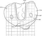
図2は、従来方法にしたがって調整された、脛骨インプラントシステム、例えば、脛骨インプラントシステム120の基部部分121を受け入れるように調整された脛骨101の近位端を示す。示されているように、調整された脛骨101は、脛骨隆起101aの各側部に床境界表面部分151a、151bを有する、床境界表面151を有する。脛骨101はまた、床境界表面151と脛骨隆起101aの上面102との間に床境界表面151に対して実質的に垂直に延びる壁境界表面153を有する。従来方法に従う、図2に示されているような脛骨の調整は、従来の鋸、例えば、振動式矢状鋸または往復式鋸を使用して、水平(床境界表面を形成するため)および垂直(壁境界表面を形成するため)両方の切削を行う。これら2セットの切削を実施する工程は、調整された骨において脛骨隆起部分101aを維持するために、非常に制御された輪郭描写を必要とする。しばしば、これらの切削は、水平または垂直のどちらの方向への切り過ぎももたらし、したがって脛骨隆起101aの強度を損なう。この従来方法のいくつかの実践において、ドリルピンが、切り過ぎを阻止し、応力集中部を減少させるのを助けるために、床境界表面151と脛骨隆起101aとの間の交差部に加えられ得る。それにもかかわらず、鋸刃は過剰に除去する傾向があり、脛骨101において水平または垂直切削を行う間、依然として切り過ぎる可能性がある。さらに、この追加の骨の破損は、追加の骨の妨害を作り出す。 FIG. 2 shows the proximal end of a tibial implant system, eg, a tibial implant system adjusted according to conventional methods, adapted to accept the
さらに、図2に示されているように、矢状鋸の使用は、鋭い角を作り出す。例えば、床境界面部分151と壁境界面部分153との間の交差部、ならびに壁境界面部分153と脛骨境界面101aの上面102との間の交差部は、脛骨隆起に対して応力を引き起こすのを減らし、その全体的な強度を減少させうる、鋭い縁を形成する。 In addition, the use of a sagittal saw creates sharp corners, as shown in Figure 2. For example, the intersection between the
図3および4は、本明細書において開示される例示的態様にしたがって調整された、脛骨インプラントシステム、例えば脛骨インプラントシステム120の基部部分121を受け入れるように調整された脛骨101の近位端を示す。示されているように、調整された脛骨101は、脛骨隆起101aの各側部に床境界表面部分151a、151bを有する、床境界表面151を有する。脛骨101はまた、床境界表面151と脛骨隆起101aの上面102との間に床境界表面151に対して実質的に垂直に延びる壁境界表面153を有する。脛骨101はまた、脛骨隆起101aの前端において、床境界表面部分151a、151bの間にブリッジ部分154を有する。最後に、脛骨101は、床境界表面151と壁境界表面153との間に湾曲した、または丸みをつけた交差部152を有する。 FIGS. 3 and 4 show the proximal end of a tibial implant system, eg, a
図3および4に示されているような脛骨の調整は、数多くの異なる手術切削ツールを使用して実施され得る。従来方法と同様に、第一のセットの切削において、床境界表面151は、振動式手術用鋸を使用して調整され得る。第二のセットの切削において、壁境界表面153はまた、矢状鋸または往復式鋸を使用して調整され得る。図3および4に示されているように、例示的態様によれば、第三のセットの切削(それぞれ床境界表面151または壁境界表面153を調整するための第一または第二のセットの切削と組み合わせて調整され得る)は、床境界表面151と壁境界表面153との間に丸みをつけた交差部152を形成するように調整される。丸みをつけた交差部152は、好ましくは、バードリル穿子またはやすりのような回転式切削ツールを使用して形成される。交差部152は、大きい半径を有する回転式カッターによって実施され得、ここで、単一通路が、丸みをつけた交差部を作り出すために必要とされるか、あるいはより小さい幾何学的形状を有するツールが、丸みをつけた交差部を形成するために彫刻ミーリング技術を実施するために使用され得る。好ましい態様において、壁境界表面153はまた、バードリル穿子または円筒形やすりのような回転式カッターを使用して調整される。このように、交差部152および壁境界表面153と脛骨隆起101aの上面102との間の上角の両方は、曲線的である。また、他の鋭い縁および応力集中部は、壁境界表面153に対する回転式カッターの使用を通して最小にされて、丸みをつけた交差部152を形成することを含むことができる。他の態様において、床境界表面151の調整はまた、バードリル穿子または円筒形やすりのような回転式切削ツールを使用して実施され得る。こうして、第一、第二または第三のセットの切削のいずれも、本開示に従って、回転式カッターを使用して実施され得る。前側ブリッジ154は、穴があけられるか、または骨鉗子で取り除かれていてもよい。好ましい態様において、前側ブリッジ154もまた、回転式カッターを使用して形成される。Tibial adjustments as shown in Figures 3 and 4 can be performed using a number of different surgical cutting tools. As in the conventional method, in the first set of cutting, the
図3および4に示された脛骨101はまた、そこに釘穴157が調整されており、それは、回転式カッターを使用して床境界表面151内に穿孔されるか、またはばり取りされ得る。釘穴157は、さらにインプラントを骨に固定し、インプラントと骨との間の動きに抵抗するために、脛骨インプラントシステム120からの細長い突出部を受け入れるように構成される。同様に、骨は、脛骨インプラントシステム120上のキールと協調し、また骨とインプラントとの間の安全性を改善する、キール(図示せず)と共に調整され得る。 The
脛骨インプラントシステムを受け入れるように脛骨を調整する方法はまた、脛骨隆起101aの強度を損なう可能性のある切り過ぎの量を制限するように、正確な切削用境界線を利用することを含む。図5は、本開示の例示的方法において使用される切削制限ガイドの一つの態様を示す。この図は、骨の調整の間になされる切削を制御するために、手術システム(以下でより詳細に説明される)と関連して提供される、触覚境界線501の実施を示す。図8に示されたシステム200のような手術システムは、計画されたプロテーゼインプラント部品と関連付けられ、かつ患者の解剖学的構造の1つまたは複数の特徴と関連付けられるかまたはそれと相対的な、仮想触覚幾何学的形状を確立するように構成され得る。手術システム200は、例えば、患者の解剖学的構造、外科手技の間に使用されるべき手術器具、手術部位内で他の物体を位置決めするためのプローブツール、および手術部位と関連付けられる任意の他のそのような物体の仮想表示を含む、手術部位の仮想表示を作り出すように構成され得る。 Methods of adjusting the tibia to accept the tibial implant system also include utilizing accurate cutting boundaries to limit the amount of overcuts that can impair the strength of the
物理的対象に加えて、手術システム200は、ソフトウェアにおいて存在し、かつ外科手技の実施の間、有用であり得る、仮想物体を生成するように構成され得る。例えば、手術システム200は、外科医が切削するか、除去するか、または他の方法で変化させる計画を立てた骨の領域を画定する境界線のような、骨を調整するための外科医の計画に対応する仮想境界線、例えば触覚境界線501を生成するように構成され得る。代替的にまたは付加的に、手術システム200は、手術ツール210の一部分が、特定の課題を実施するために進むべき、所望の通路または進路に対応する仮想物体を画定し得る。 In addition to physical objects, the
仮想境界線および他の仮想物体は、手術器具の追跡された位置が仮想境界線または物体と接触すると、触覚フィードバックが手術器具に与えられる境界線として役立つ、仮想座標空間内部の点、線または表面を画定し得る(典型的には、患者の解剖学的構造に相対的に画定される)。例えば、外科医が骨切削動作を実施しているとき、手術システム200の追跡システムは、切削ツールの位置を追跡し、大抵の場合は、外科医が作業空間内でツールを自由に動かすことを可能にする。しかしながら、ツールが、仮想触覚境界線(患者の解剖学的構造に対して位置決めされている)に近接している場合、手術システム200は、力フィードバックシステムを制御して、外科医が切削ツールで仮想触覚境界線に侵入することを妨げるのに役立つ触覚ガイダンスを提供する。例えば、仮想触覚境界線は、プロテーゼインプラントの仮想モデルの幾何学的形状と関連付けら得、触覚ガイダンスは、ツールの動きが仮想境界線に侵入することを妨げるために、仮想境界線に対してマッピングされ、かつ外科医によって抵抗として経験される、力および/またはトルクを含み得る。したがって、外科医は、切削ツールが物理的物体、例えば壁に遭遇したかのように感じ得る。したがって、手術システム200の力フィードバックシステムは、仮想境界線に対するツールの位置に関して情報を外科医に伝達し、物理的力フィードバックを提供して、実際の切削プロセスの間、切削ツールをガイドする。このようにして、仮想境界線は、仮想切削ガイドとして機能する。手術システム200の力フィードバックシステムはまた、手術ツールを操作する使用者の能力を制限するように構成され得る。 Virtual boundaries and other virtual objects are points, lines or surfaces within the virtual coordinate space where tactile feedback serves as the boundary given to the surgical instrument when the tracked position of the surgical instrument comes into contact with the virtual boundary or object. Can be defined (typically defined relative to the patient's anatomical structure). For example, when a surgeon is performing a bone cutting motion, the tracking system of the
図5に示されているように、例示的触覚境界線501は、作業領域502内での手術ツールの操作を可能にするように生成される。触覚境界線501は、所望の脛骨隆起領域101a周りに位置される。このようにして、外科医は、切り過ぎて脛骨隆起101aの強度を損なうことなく、床境界表面151および前側ブリッジ部分154を作り出すように脛骨101に切削を行うことができる。示されているように、触覚境界線501は、ツールが接近しすぎた切削をしないように、計画された脛骨隆起101aから所望のずれたところに作り出される。触覚境界線501は、使用されるべき脛骨インプラントシステムに基づいて自動的に生成され得、また外科医によってカスタマイズもされ得る。例えば、外科医は、触覚境界線501の大きさを増大するかまたは縮小することを望み得るか、計画された脛骨隆起101aからの境界線のずれを変更することを望み得るか、あるいは患者の解剖学的構造上の計画されたインプラントシステムの再位置付けを、したがって触覚境界線501の再位置付けを望み得る。手術システム200は、ユーザーインターフェースを通して外科医によってこれらの入力を可能にするように構成され得る。開示された態様に従う骨調整を完了するために、追加の触覚境界線が生成されて、その他のセットの切削のために、例えば、壁境界表面を切削するために、手術ツールに適用され得る。 As shown in FIG. 5, the exemplary
手術システムを通して生成され、適用される触覚境界線の使用は、本方法を実施するための切削制限ガイドを作り出すための一つの機構である。切削制限ガイドの他の態様は、切削ツールまたは切削ツールを保持するアームに適用され得る機械的制限を含むか、あるいは外科医が手術計画に従ってツールを操作することを可能にするために手術計画に特有に作り出される切削ブロックであり得る。 The use of tactile boundaries generated and applied through the surgical system is one mechanism for creating cutting restriction guides for carrying out the method. Other aspects of the cutting limit guide include mechanical limits that may be applied to the cutting tool or the arm holding the cutting tool, or are specific to the surgical plan to allow the surgeon to operate the tool according to the surgical plan. It can be a cutting block produced in.
先に記載されたとおりの関節の調整は、図6に示されている例示的態様に従って実施され得る。骨を調整する方法は、脛骨上の床境界表面151を調整するために第一のセットの切削を実施する工程を含む(工程601)。床境界表面151は、脛骨101上の床境界表面151より上に延びる脛骨隆起101aの各側部に部分151a、151bを含む。本方法はさらに、脛骨隆起壁境界表面153を調整するために第二のセットの切削を実施する工程を含む(工程602)。壁境界表面153は、床境界表面151と脛骨隆起101aの上面102との間に床境界表面151に対して実質的に垂直に延びる。本方法はさらに、床境界表面と壁境界表面との間に丸みをつけた交差部を調整するために第三のセットの切削を実施する工程を含む(工程603)。先に説明されたように、これらのセットの切削は、切削制限ガイドの影響下で実施される。他の態様において、工程601、602、および603は、図6に示されているものとは異なる順番で実施され得る。同様に、第三のセットの切削(工程603)は、工程601または工程602と連動して実施されることができる(これらの工程が回転式カッターを使用した切削を含む場合)。前述されたように、これらのセットの切削のうちの1つまたは複数は、回転式カッターを使用して実施され得る。 Adjustment of the joint as described above can be performed according to the exemplary embodiment shown in FIG. The method of adjusting the bone comprises performing a first set of cuttings to adjust the
先に記載されたような関節の調整のための計画を立てることは、図7に示されている例示的態様に従って実施され得る。手術計画を立てる方法は、脛骨の近位端の表示を獲得する工程を含む(工程701)。解剖学的構造の表示は、撮像システムによって獲得され得るし、CTまたはMRI画像のような画像を含み得る。画像は、手術前に、手術中に、または手術計画を立てる時点で、獲得され得る。画像は、以下に記載される手術システム200を通してロードされて獲得され得る。本方法はまた、脛骨インプラントの表示を獲得する工程を含む(工程702)。モデルインプラントもまた、手術システム200を通してロードされて獲得され得る。外科医は、数多くの様々なインプラントモデルから選択し、患者および患者の解剖学的構造に最も適切なインプラントを選ぶことができ得る。計画を立てる方法はさらに、脛骨の近位端の表示上に脛骨インプラントの表示を位置付ける工程、および脛骨インプラントに基づいて脛骨の近位端の調整を計画する工程を含む(工程703)。外科医は、患者の解剖学的構造上のインプラントの位置を修正することができ得る。骨の表示上にモデルインプラントを位置付ける工程は、脛骨101上の床境界表面151を調整するために第一のセットの切削を計画する工程を含む、脛骨インプラントを受け入れるように骨を調整するのに必要な切除を計画する工程を可能にさせる(工程704)。床境界表面151は、脛骨隆起101aの各側部に部分151a、151bを含み、脛骨隆起101aは脛骨上の床境界面部分より上に延びる。工程705は、脛骨隆起壁境界表面153を調整するために第二のセットの切削を計画する工程を含む。壁境界表面153は、床境界表面151と脛骨隆起101aの上面102との間に床境界表面151に対して実質的に垂直に延びる。工程706は、床境界表面151と壁境界表面153との間に丸みをつけた交差部152を調整するために第三のセットの切削を計画する工程を含む。本方法はさらに、第一、第二、および第三のセットの切削のうち少なくとも1つの計画に基づいて、切削制限ガイドを提供する工程を含む(工程707)。 Planning for joint adjustment as described above can be performed according to the exemplary embodiments shown in FIG. The method of planning surgery involves obtaining an indication of the proximal end of the tibia (step 701). An indication of the anatomical structure can be obtained by an imaging system and can include images such as CT or MRI images. Images can be acquired before, during, or at the time of planning surgery. Images can be loaded and acquired through the
先に記載された例示的態様の方法に従う関節の正確かつ的確な調整を確実にするための例示的アプローチは、外科医が患者の解剖学的構造との接触の前にツールを適切に整列し、骨に的確な切削を実施するのを助ける、コンピューター支援手術(CAS)システムを利用し得る。多くのCASシステムは、ユーザが特定の解剖学的特徴(例えば、骨、軟部組織等)、手術器具、および手術部位と関連付けられる他の標認点を電子的に位置決めすることを可能にするソフトウェアを含む。CASシステムは、解剖学的特徴の位置決めに基づいて、手術部位のグラフィカル表示を生成し得る。CASソフトウェアはまた、ユーザが外科手技の特定の局面を計画し、これらの局面を手術部位のグラフィカル表示と共に表示するために位置決めすることが可能である。例えば、膝関節置換手技において、外科医は、標的ナビゲーション点、骨および組織切削の位置および深さ、触覚力の適用のために対応する参照と関連付けられ得る仮想境界線、および手術の他の局面を位置決めし得る。 An exemplary approach to ensure accurate and precise adjustment of the joint according to the method of the exemplary embodiment described above allows the surgeon to properly align the tool prior to contact with the patient's anatomy. Computer-assisted surgery (CAS) systems can be used to help perform the correct cutting of the bone. Many CAS systems are software that allows the user to electronically position specific anatomical features (eg, bone, soft tissue, etc.), surgical instruments, and other marking points associated with the surgical site. including. The CAS system can generate a graphical representation of the surgical site based on the positioning of anatomical features. CAS software can also allow the user to plan and position specific aspects of the surgical procedure to display with a graphical display of the surgical site. For example, in a knee replacement procedure, the surgeon sees target navigation points, bone and tissue cutting positions and depths, virtual boundaries that can be associated with corresponding references for the application of tactile forces, and other aspects of surgery. Can be positioned.
図8は、例示的コンピューター支援手術(CAS)システム200の概略図を提供しており、ここで、特定の開示された態様と関連付けられるプロセスおよび特徴が、実現され得る。手術システム200は、例えば、部分または全関節置換手術のような様々な整形外科手技を実施するように構成され得る。図2に図示されているように、手術システム200は、追跡システム201、コンピューターシステム202、1つまたは複数の表示デバイス203a、203b、およびロボットシステム204を含む。システム200、ならびに本明細書において記載される方法およびプロセスが、多くの異なるタイプの関節置換術に適用可能であり得ることが認識されるべきである。特定の開示された態様は、膝置換術に関して記載されている場合があるが、本明細書において記載される概念および方法は、股関節部分置換、全または部分股関節面置換(hip resurfacing)、肩関節置換または肩関節面置換術、および他のタイプの整形外科手技のような他のタイプの整形外科手術に適用可能であり得る。 FIG. 8 provides a schematic of an exemplary computer-assisted surgery (CAS)
ロボットシステム204は、患者に膝置換術のような外科手技を実施するために、外科医によって相互作用式に使用されることができる。図2に示されるように、ロボットシステム204は、基部205、関節式アーム206、力システム(図示せず)、およびコントローラー(図示せず)を含む。手術ツール210(例えば、鋸、リーマ、またはバードリル穿子のような作業部材を有するエンドエフェクタ)は、関節式アーム206に結合され得る。外科医は、関節式アーム206および/または手術ツール210を把持し、手動で動かすことによって、手術ツール210を操作することができる。 The
力システムおよびコントローラーは、手術ツールの操作中、制御またはガイダンスを介して外科医へ切削制限ガイドを提供するように構成される。力システムは、関節式アーム206を介して少なくともいくらかの力を手術ツールに提供するように構成されており、コントローラーは、力システムを制御するために制御信号を生成するようにプログラムされている。一つの態様において、例えば、2009年12月22日に出願された米国特許第8,010,180号および/または米国特許出願第12/654,519号(米国特許出願公開第2010/0170362号)(これらの各々は参照により全体として本明細書に組み入れられる)に記載されているように、力システムは、外科医が、触覚物体によって画定されている予め画定された触覚境界線を越えて手術ツールを手動で動かすことを制約するかまたは阻むために触覚(または力)フィードバックを提供する、アクチュエーターおよびバックドライブ可能な伝動装置を含む。一つの態様によれば、手術システム200は、MAKO Surgical Corp. (Fort Lauderdale, Florida)によって製造されているRIO(登録商標)Robotic Arm Interactive Orthopedic Systemである。力システムおよびコントローラーは、ロボットシステム204内部に収容され得る。 The force system and controller are configured to provide the surgeon with a cutting restriction guide through control or guidance during the operation of the surgical tool. The force system is configured to provide at least some force to the surgical tool via the articulated
追跡システム201は、外科手技の間、1つまたは複数の物体の姿勢(すなわち、位置および向き)を決定して物体の動きを検出するように構成される。例えば、追跡システム201は、検出デバイスを含み得、それは、検出デバイスの参照の座標フレームに対する物体の姿勢を得る。物体が、参照の座標フレーム内で動くと、検出デバイスは、物体の姿勢を追跡して、物体の動きを検出する(または手術システム200が決定することができる)。結果として、コンピューターシステム202は、追跡される1つまたは複数の物体の動きに応じてデータを捕獲することができる。追跡される物体は、例えば、ツール/器具、患者の解剖学的構造、インプラント/プロテーゼデバイス、および手術システム200の部品を含み得る。追跡システム201からの姿勢データを使用して、手術システム200はまた、1つの空間内の座標を別の空間内の座標に対して位置決めして(またはマッピングするかまたは関連付ける)、空間アラインメントまたは対応を達成することができる(例えば、周知のような座標変換法を使用して)。物理的空間内の物体は、手術用コントローラー212および/または触覚デバイス204のコンピューターデバイス上で実行するプロセスによって使用されている座標システムのような任意の適切な座標システムに位置決めされ得る。例えば、追跡システム201からの姿勢データを利用して、手術システム200は、患者の脛骨のような物理的な解剖学的構造を、解剖学的構造の表示(例えば、表示デバイス203上に表示された画像)と関連付けることができる。追跡された物体および位置決めデータに基づいて、手術システム200は、例えば、解剖学的構造の画像と関連した解剖学的構造との間の空間的な関係を決定し得る。 The
位置決めは、例えば、画像対画像位置決め(例えば、同じタイプまたはモダリティの画像、例えば、蛍光透視画像またはMR画像が位置決めされる単一モードの位置決め、および/またはMRIおよびCTのような異なるタイプまたはモダリティの画像が位置決めされる多モードの位置決め);画像対物理的空間位置決め(例えば、従来の撮像技術によって得られた患者の解剖学的構造のデジタルデータセットが患者の実際の解剖学的構造と共に位置決めされる、画像対患者位置決め);および/または、画像対画像および画像対物理的空間を組み合わせた位置決め(例えば、術前CTおよびMRI画像の術中の場面に対する位置決め)のような任意の公知の位置決め技術を含み得る。コンピューターシステム202はまた、1つの空間内の座標を別の空間内の座標へマッピングして(変換して)空間アラインメントまたは対応を達成するための座標変換法を含み得る。例えば、手術システム200は、触覚デバイスのコンピューターおよび/または手術用コントローラー212上で実行するプロセスによって使用される座標システムに、追跡された物体(例えば、患者の解剖学的構造など)の位置をマッピングするために、座標変換法を使用し得る。周知のように、座標変換法は、例えば、剛体変換、非剛体変換、アフィン変換などのような任意の適切な変換技術を含み得る。 Positioning is, for example, image-to-image positioning (eg, single-mode positioning in which images of the same type or modality, such as fluorescence fluoroscopic or MR images, are positioned, and / or different types or modalities such as MRI and CT. Image vs. physical spatial positioning (eg, a digital dataset of the patient's anatomical structure obtained by conventional imaging techniques is positioned along with the patient's actual anatomical structure). Image-to-patient positioning); and / or any known positioning such as image-to-image and image-to-physical space combination positioning (eg, positioning of preoperative CT and MRI images for intraoperative scenes). May include technology. The
追跡システム201は、手術システム200が患者の関連する解剖学的構造の姿勢を絶えず決定する(または追跡する)ことができる、任意の追跡システムであり得る。例えば、追跡システム201は、手術環境での使用に適する、非機械的追跡システム、機械的追跡システム、または非機械的および機械的追跡システムの任意の組合せを含み得る。非機械的追跡システムは、光学的(または視覚的)、磁気、無線、または音響追跡システムを含み得る。そのようなシステムは、典型的には、検出デバイスによって検出可能であり、追跡されるべき物体に取り付けられるように構成されるか、または追跡されるべき物体の生来部分であるかのいずれかである、追跡可能な要素(または追跡器)を特に認識可能な、予め画定された座標空間内に定まるように適応された検出デバイスを含む。例えば、追跡可能な要素は、追跡可能な要素が追跡される物体に取り付けられる場合、追跡される物体に対する特有の幾何学的配置および公知の幾何学的関係を有する一連のマーカーを含み得る。公知の幾何学的関係は、例えば、追跡可能な要素と追跡される物体の終点および軸との間の予め定められた幾何学的関係であり得る。したがって、検出デバイスは、マーカーの幾何学的形状(一意的な場合)、軸の向き、およびマーカーの位置から導き出された参照のフレーム内部の終点の位置から、特定の追跡される物体を少なくとも部分的に認識することができる。 The
マーカーは、例えば、外来性マーカー(または基準)および/または追跡される物体の内因性特徴のような任意の公知のマーカーを含み得る。外来性マーカーは、患者に取り付けられる人工物体(例えば、皮膚に張られるマーカー、骨内に埋め込まれるマーカー、定位フレームなど)であり、検出デバイスによって可視で的確に検出可能であるように設計される。内因性特徴は、認識可能なマーカーとして働くのに十分に画定され、かつ識別可能である、追跡される物体の突出し、かつ的確に捜し当てることができる部分である(例えば、標認点、解剖学的構造の輪郭、形状、色、または任意の他の十分に認識可能な可視的指標)。マーカーは、周知であるような、例えば、光学的、電磁、無線、または音響方法のような任意の適切な検出方法を使用して捜し出され得る。例えば、赤外線に感受性がある固定ステレオカメラ対を有する光学的追跡システムが、能動的(例えば、発光ダイオードすなわちLED)か、または受動的(例えば、赤外線を反射する表面を有する球形マーカー)かのいずれかで赤外線を発するマーカーを追跡するために使用され得る。同様に、磁気追跡システムは、追跡される物体内に一体化された小コイルによって感知される空間的に変化する磁場を放出する、定常場発生器を含み得る。 The marker may include any known marker, such as, for example, an exogenous marker (or reference) and / or an intrinsic feature of the object being tracked. An exogenous marker is an artificial object attached to a patient (eg, a marker placed on the skin, a marker embedded in bone, a stereotactic frame, etc.) and is designed to be visible and accurately detectable by a detection device. .. Intrinsic features are prominent and precisely locable parts of a tracked object that are sufficiently defined and identifiable to act as recognizable markers (eg, marking points, anatomy). Anatomical contours, shapes, colors, or any other well-recognizable visible indicator). Markers can be sought using any suitable detection method, such as known, for example, optical, electromagnetic, radio, or acoustic methods. For example, an optical tracking system with a fixed stereo camera pair that is sensitive to infrared light is either active (eg, a light emitting diode or LED) or passive (eg, a spherical marker with a surface that reflects infrared light). It can be used to track markers that emit infrared light. Similarly, a magnetic tracking system may include a stationary field generator that emits a spatially varying magnetic field sensed by a small coil integrated within the tracked object.
コンピューターシステム202は、追跡システム201に通信可能に結合され得、かつ追跡データを追跡システム201から受信するように構成され得る。受信された追跡データに基づいて、コンピューターシステム202は、手術環境の1つまたは複数の位置決めされた特徴、例えば手術ツール210または患者の解剖学的構造の部分と関連付けられた位置および向きを決定し得る。コンピューターシステム202はまた、外科手技の間、外科医または手術サポートスタッフによって使用され得る、手術計画および手術補助ソフトウェアを含み得る。例えば、関節置換術の間、コンピューターシステム202は、表示デバイス203a、203bの一方または両方に、外科手技に関する画像を表示し得る。 The
コンピューターシステム202(および/または手術システム200の1つまたは複数の構成部品)は、手術システム200の動作および制御のためのハードウェアおよびソフトウェアを含み得る。そのようなハードウェアおよび/またはソフトウェアは、システム200が本明細書に記載されている技術を実施することができるように構成されている。図9を参照すると、コンピューターシステム202は、手術用コントローラー212、表示デバイス203、および入力デバイス216を含む。 The computer system 202 (and / or one or more components of the surgical system 200) may include hardware and software for the operation and control of the
手術用コントローラー212は、任意の公知のコンピューターシステムであり得るが、好ましくは、プログラム可能な、プロセッサーベースのシステムである。例えば、手術用コントローラー212は、マイクロプロセッサー、ハードドライブ、ランダムアクセスメモリー(RAM)、読出し専用メモリー(ROM)、入出力(I/O)回路、および任意の他の公知のコンピューター部品を含み得る。手術用コントローラー212は、好ましくは、例えば、携帯用駆動装置、磁気記憶装置、固体記憶装置(例えば、フラッシュメモリカード)、光学式記憶装置、および/またはネットワーク/インターネット記憶装置のような種々のタイプの記憶デバイス(永続的および着脱可能な)と共に使用するように適応される。手術用コントローラー212は、例えば、パーソナルコンピューターまたは適切なオペレーティングシステムの下で動作するワークステーションを含む、1つまたは複数のコンピューターを含み得、好ましくは、グラフィカルユーザーインターフェース(GUI)を含む。 The
再び図9を参照すると、例示的態様において、手術用コントローラー212は、プロセッサー222およびメモリー224を有する処理回路220を含む。プロセッサー222は、1つまたは複数のコンピュータープログラムを実行する汎用プロセッサーとして実現されて、入力データに対して作用して出力を生成することによって機能を果たすことができる。プロセスおよび論理の流れは、専用論理回路、例えば、FPGA(フィールドプログラマブルゲートアレイ)またはASIC(特定用途向け集積回路)、一群の処理部品、または他の適切な電子処理部品によって実施されることもでき、装置は、専用論理回路、例えば、FPGA(フィールドプログラマブルゲートアレイ)またはASIC(特定用途向け集積回路)、一群の処理部品、または他の適切な電子処理部品として実現されることもできる。一般に、プロセッサーは、読出し専用メモリーまたはランダムアクセスメモリーまたは両方から命令およびデータを受信するであろう。メモリー224(例えば、メモリー、メモリーユニット、記憶デバイスなど)は、本願に記載されている種々のプロセスを完了するか、または促進するためのデータおよび/またはコンピューターコードを格納するための1つまたは複数のデバイス(例えば、RAM、ROM、フラッシュメモリー、ハードディスク記憶装置など)を含む。メモリー224は、揮発性メモリーまたは不揮発性メモリーであり得るか、またはそれらを含み得る。メモリー224は、本願に記載されている種々の活動を支持するための、データベース構成要素、オブジェクトコード構成要素、スクリプト構成要素、または任意の他のタイプの情報構造を含み得る。例示的態様によれば、メモリー224は、プロセッサー222に通信可能に接続されており、本明細書に記載されている1つまたは複数のプロセスを実行するためのコンピューターコードを含む。メモリー224は、各々、特定のタイプの機能に関するデータおよび/またはコンピューターコードを格納することができる、種々のモジュールを含み得る。一つの態様において、メモリー224は、外科手技に関する幾つかのモジュール、例えば、計画モジュール224a、ナビゲーションモジュール224b、位置決めモジュール224c、およびロボット制御モジュール224dを含む。 With reference to FIG. 9 again, in an exemplary embodiment, the
代替的に、または加えて、プログラム命令は、データ処理装置による実行のために適した受信装置への送信のために情報を符号化するために生成される、人工的に生成した伝搬信号、例えば、機械が生成した電気、光、または電磁信号に符号化されることができる。コンピューター記憶媒体は、コンピューター可読記憶デバイス、コンピューター可読記憶基板、ランダムまたは逐次アクセスメモリーアレイもしくはデバイス、またはそれらの1つまたは複数の組合せであることができるか、またはそれらに含まれることができる。さらに、コンピューター記憶媒体は、伝搬信号でないが、コンピューター記憶媒体は、人工的に生成した伝搬信号中に符号化されたコンピュータープログラム命令の源または目的地であることができる。コンピューター記憶媒体はまた、1つまたは複数の別個の部品または媒体であることができるか、またはそれらに含まれることができる(例えば、複数のCD、ディスク、または他の記憶デバイス)。したがって、コンピューター記憶媒体は、有形および非一時的であり得る。 Alternatively, or in addition, a program instruction is an artificially generated propagating signal, eg, generated to encode information for transmission to a receiver suitable for execution by a data processor. Can be encoded into a machine-generated electric, optical, or electromagnetic signal. The computer storage medium can be, or can be contained in, a computer-readable storage device, a computer-readable storage board, a random or sequential access memory array or device, or one or a combination thereof. Further, although the computer storage medium is not a propagating signal, the computer storage medium can be the source or destination of computer program instructions encoded in the artificially generated propagating signal. Computer storage media can also be one or more separate parts or media, or can be included in them (eg, multiple CDs, discs, or other storage devices). Therefore, computer storage media can be tangible and non-temporary.
コンピュータープログラム(プログラム、ソフトウェア、ソフトウェアアプリケーション、スクリプト、またはコードとしても知られている)は、コンパイラ型またはインタープリタ型言語、宣言型または手続き型言語を含む、任意の形式のプログラミング言語で書かれることができ、それは、スタンドアローンのプログラムとして、またはモジュール、コンポーネント、サブルーチン、オブジェクト、またはコンピューター環境での使用に適した他のユニットとして挙げられる、任意の形式で配備されることができる。コンピュータープログラムは、ファイルシステム内のファイルに対応し得るが、対応する必要はない。プログラムは、他のプログラムまたはデータ(例えば、マークアップ言語文書内に格納されている1つまたは複数のスクリプト)を保持するファイルの一部分内、問題になっているプログラムのために割り当てられた単一ファイル内、または複数の座標ファイル(例えば、1つまたは複数のモジュール、サブプログラム、またはコードの部分を格納するファイル)内に、格納されることができる。コンピュータープログラムは、1つのコンピューターで、または1つの場所に位置されているか、もしくは複数の場所にわたって分布されて通信ネットワークによって相互接続されている複数のコンピューターで、実行されるように配備されることができる。 Computer programs (also known as programs, software, software applications, scripts, or code) can be written in any form of programming language, including compiler or interpreter languages, declarative or procedural languages. It can be deployed in any form, listed as a stand-alone program or as a module, component, subroutine, object, or other unit suitable for use in a computer environment. Computer programs can, but do not need to, support files in the file system. A program is a single assigned for the program in question, within a portion of a file that holds other programs or data (eg, one or more scripts stored within a markup language document). It can be stored in a file or in multiple coordinate files (eg, a file that contains one or more modules, subprograms, or parts of code). Computer programs may be deployed to run on one computer, or on multiple computers that are located in one location or distributed across multiple locations and interconnected by communication networks. it can.
一般に、コンピューターはまた、データを格納するための1つまたは複数の大容量記憶デバイス、例えば、磁気、光磁気ディスク、または光ディスクを含むか、あるいはそれらからデータを受信するか、またはそれらにデータを転送するか、またはその両方を行うために動作可能なように結合されるであろう。しかしながら、コンピューターは、そのようなデバイスを有する必要はない。さらに、コンピューターは、別のデバイス、例えば数例だけ挙げると、携帯電話、携帯情報端末(PDA)、携帯オーディオまたはビデオプレーヤー、ビデオゲーム機、全地球測位システム(GPS)受信機、または携帯用記憶デバイス(例えば、ユニバーサルシリアルバス(USB)フラッシュドライブ)内に埋め込まれることができる。コンピュータープログラム命令およびデータを格納するために適したデバイスは、例として、半導体メモリーデバイス、例えば、EPROM、EEPROM、およびフラッシュメモリーデバイス;磁気ディスク、例えば、内蔵のハードディスクまたはリムーバブルディスク;光磁気ディスク;およびCD ROMおよびDVD-ROMディスクを含む、不揮発性メモリー、媒体およびメモリーデバイスの全ての形式を含む。プロセッサーおよびメモリーは、専用論理回路によって補われるか、またはそれに組み込まれることができる。 In general, computers also include or receive data from one or more mass storage devices for storing data, such as magnetic, magneto-optical disks, or optical disks, or deliver data to them. It will be combined to be operational to transfer or both. However, the computer does not need to have such a device. In addition, computers can be other devices, such as mobile phones, personal digital assistants (PDAs), portable audio or video players, video game consoles, Global Positioning System (GPS) receivers, or portable storage, to name just a few. It can be embedded within a device (eg, a universal serial bus (USB) flash drive). Suitable devices for storing computer program instructions and data include, for example, semiconductor memory devices such as EPROM, EEPROM, and flash memory devices; magnetic disks such as internal hard disks or removable disks; magneto-optical disks; and Includes all types of non-volatile memory, media and memory devices, including CD ROM and DVD-ROM discs. Processors and memory can be supplemented or incorporated into dedicated logic circuits.
本明細書に記載されている対象の態様は、バックエンド部品を例えばデータサーバーとして含むか、またはミドルウェア部品、例えばアプリケーションサーバーを含むか、またはフロントエンド部品、例えば、ユーザが本明細書に記載されている対象の態様と対話することができるグラフィカルユーザーインターフェースまたはウェブブラウザーを有するクライアントコンピューターを含む、コンピューターシステム、あるいは1つまたは複数のそのようなバックエンド、ミドルウェア、またはフロントエンド部品の任意の組合せで実現されることができる。当該システムの部品は、デジタルデータ通信の任意の形式または媒体、例えば、通信ネットワークによって相互接続されることができる。通信ネットワークの例は、ローカルエリアネットワーク(「LAN」)および広域ネットワーク(「WAN」)、インターネットワーク(例えば、インターネット)、およびピアツーピアネットワーク(例えば、アドホックピアツーピアネットワーク)を含む。 The aspects of interest described herein include a back-end component, eg, as a data server, or a middleware component, eg, an application server, or a front-end component, eg, a user described herein. In a computer system, including a client computer with a graphical user interface or web browser that can interact with the aspect of the subject, or in any combination of one or more such backends, middleware, or frontend components. Can be realized. The components of the system can be interconnected by any form or medium of digital data communication, such as a communication network. Examples of communication networks include local area networks (“LAN”) and wide area networks (“WAN”), internetworks (eg, the Internet), and peer-to-peer networks (eg, ad hoc peer-to-peer networks).
図9に示される手術システム200の態様を参照すると、手術用コントローラー212はさらに、通信インターフェース230を含む。コンピューターシステム202の通信インターフェース230は、インターフェースを介してロボットシステム204のコンピューターデバイス(図示せず)に、およびインターフェースを介して追跡システム201に、結合されている。インターフェースは、物理インターフェースおよびソフトウェアインターフェースを含むことができる。通信インターフェース230の物理インターフェースは、直接接続またはネットワーク接続(例えば、インターネット接続、LAN、WAN、またはWLAN接続など)を介して外部源とデータ通信を行うための、有線または無線のインターフェース(例えば、ジャック、アンテナ、送信機、受信機、トランシーバー、ワイヤー端子など)であるか、またはそれらを含むことができる。ソフトウェアインターフェースは、手術用コントローラー212、ロボットシステム204のコンピューターデバイス(図示せず)、および/または追跡システム201に常駐し得る。いくつかの態様において、手術用コントローラー212およびコンピューターデバイス(図示せず)は、同じコンピューターデバイスである。ソフトウェアはまた、手術システム200と同じ建物内に収容されているか、または外部サーバーサイトにある、リモートサーバー上で動作し得る。 With reference to aspects of the
コンピューターシステム202はまた、表示デバイス203を含む。表示デバイス203は、コンピューターシステム52とユーザとの間のビジュアルインターフェースである。表示デバイス203は、手術用コントローラー212に接続されており、テキスト、画像、グラフィックス、および/または他の視覚的出力を表示するために適した任意のデバイスであり得る。例えば、表示デバイス203は、標準的な表示画面(例えば、LCD、CRT、OLED、TFT、プラズマなど)、タッチスクリーン、ウェアラブルディスプレー(例えば、メガネまたはゴーグルのようなアイウェア)、投写型ディスプレー、ヘッドマウントディスプレー、ホログラフィックディスプレー、および/または任意の他の視覚的出力デバイスを含み得る。表示デバイス203は、手術用コントローラー212上またはその近くに配置され得るか(例えば、図8に示されているようにカート上に)、あるいは手術用コントローラー212から遠隔であり得る(例えば、追跡システム56ともに台上に据え付けられる)。表示デバイス203は、好ましくは、ユーザが外科手技の間、必要に応じて表示デバイス203を位置付ける/再位置付けすることができるように、調節可能である。例えば、表示デバイス203は、調節可能アーム(図示せず)上か、またはユーザが容易に見られるようによく適している任意の他の場所に、配置され得る。図8に示されるように、手術システム200内に1つより多い表示デバイス203があってもよい。 The
表示デバイス203は、医学的手技に有用な任意の情報、例えば、従来の撮像技術を使用して得られた画像データセットから生成された解剖学的構造の画像、グラフィックモデル(例えば、インプラント、器具、解剖学的構造などのCADモデル)、追跡される物体(例えば、解剖学的構造、ツール、インプラントなど)のグラフィカル表示、制約データ(例えば、軸、関節表面など)、インプラント部品の表示、デジタルまたはビデオ画像、位置決め情報、較正情報、患者データ、ユーザデータ、測定データ、ソフトウェアメニュー、選択ボタン、状態情報などを、表示するために使用され得る。 The
表示デバイス203に加えて、コンピューターシステム202は、可聴フィードバックをユーザに提供するために音響デバイス(図示せず)を含み得る。音響デバイスは、手術用コントローラー212に接続されており、音を発するための任意の公知のデバイスであり得る。例えば、音響デバイスは、スピーカーおよびサウンドカード、一体化したオーディオサポートを有するマザーボード、ならびに/または外部サウンドコントローラーを含み得る。動作において、音響デバイスは、情報をユーザに伝達するように適応され得る。例えば、手術用コントローラー212は、音響デバイスに信号を送り、合成音声の言葉による指摘「終了しました」のような音を発生させて、外科手技の工程が完了したことを指摘するようにプログラムされ得る。同様に、音響デバイスは、手術切削ツールが軟部組織の危険な部分に近づいているか、または触覚境界線に接近していることを示すために発信音を発生させるような、繊細な状況に対してユーザに警報を出すために使用され得る。 In addition to the
ユーザとの他の対話を提供するために、本明細書に記載されている主題の態様は、ユーザが手術システム200と通信できるようにする入力デバイス216を有するコンピューターで実現されることができる。入力デバイス216は、手術用コントローラー212に接続されており、ユーザが入力をコンピューターに提供できるようにする任意のデバイスを含み得る。例えば、入力デバイス216は、公知の入力デバイス、例えば、キーボード、マウス、トラックボール、タッチスクリーン、タッチパッド、音声認識ハードウェア、ダイヤル、スイッチ、ボタン、追跡可能なプローブ、足踏みペダル、リモートコントロールデバイス、スキャナー、カメラ、マイクロホン、および/またはジョイスティックであることができる。例えば、入力デバイス216は、先に説明されたようにユーザが触覚境界線を操作することを可能にすることができる。他の種類のデバイスが、ユーザとの対話を提供するために使用されることもでき;例えば、ユーザに提供されるフィードバックは、任意の形態の感覚フィードバック、例えば、視覚フィードバック、聴覚フィードバック、または触覚フィードバックであることができ;ユーザからの入力は、音響、音声、または触覚入力を含む、任意の形態で受けられることができる。加えて、コンピューターは、ユーザによって使用されるデバイスに文書を送信し、そこから文書を受信することによって;例えば、ユーザのクライアントデバイス上のウェブブラウザーから受信した要求に応じて、そのウェブブラウザーにウェブページを送信することによって、ユーザと対話することができる。 To provide other interactions with the user, aspects of the subject matter described herein can be implemented on a computer having an
手術システム200に関連して記載されたような触覚制御およびフィードバックを含む、先に記載された例示的方法を実施するための全体的な手術計画およびナビゲーションは、Quaidらに付与された米国特許第8,010,180号「Haptic Guidance System and Method」(それは、参照により全体として本明細書に組み入れられる)に記載されているもののようなコンピューター化された手術システムによって実施され得る。 The overall surgical plan and navigation for implementing the exemplary methods described above, including tactile control and feedback as described in connection with
種々の例示的態様において示されたとおりのシステムおよび方法の構造および配置は、単に例示である。幾つかの態様のみが、本開示において詳細に記載されたが、多くの修正が可能である。したがって、そのような修正のすべてが、本開示の範囲内に含まれることが意図される。いかなるプロセスまたは方法工程の順番または順序は、代替態様に従って変更されるか、または並べ直され得る。他の置換、修正、変更、および省略が、本開示の範囲から逸脱することなく、例示的態様の設計、動作条件および配置において、なされ得る。 The structures and arrangements of the systems and methods as shown in the various exemplary embodiments are merely exemplary. Only a few aspects have been described in detail in this disclosure, but many modifications are possible. Therefore, all such modifications are intended to be included within the scope of this disclosure. The order or order of any process or method step may be modified or rearranged according to alternative embodiments. Other substitutions, modifications, modifications, and omissions may be made in the design, operating conditions, and arrangement of exemplary embodiments without departing from the scope of the present disclosure.
Claims (13)
Translated fromJapanese骨の表示を獲得する工程;
インプラント部品の表示を獲得する工程;
骨の該表示上にインプラント部品の該表示を位置付ける工程;
床境界表面を該骨上に調整するために第一のセットの切削を計画する段階;
該床境界表面に対して実質的に垂直に延びる壁境界表面を調整するために第二のセットの切削を計画する段階;および
該床境界表面と該壁境界表面との間に丸みをつけた交差部を調整するために第三のセットの切削を計画する段階を含む、
該インプラント部品に基づいて骨の調整を計画する工程;ならびに
該第一、第二、および第三のセットの切削のうち少なくとも1つの計画に特有である仮想物体であって、切削用境界線を定義する該仮想物体を生成し、かつ、該仮想物体を骨の仮想表示と関連付けること、および
該第一、第二、および第三のセットの切削のうち少なくとも1つを実施するために手術ツールが用いられている間、該手術ツールの動きを該切削用境界線に物理的に制約するべく、該フィードバック機構を該仮想物体に基づいて制御すること
による、
切削制限ガイドを提供する工程。A method of operating a computer assisted surgery system which includes a feedback mechanism,comprising the following steps, the following stepsare the computer assisted surgery systemto execute a method:
The process of obtaining a bone display;
The process of obtaining a label for an implant component;
The process of positioning the indication of the implant component on the indication of the bone;
The stage of planning the first set of cuts to adjust the floor boundary surface onto the bone;
Rounded between and floor boundary surface and the wall bounding surface; substantially phase plan the cutting of the second set in order to adjust the vertically extending walls bounding surface against the floor boundarytable surface Including the stage of planning a third set of cutting to adjust the intersection,
The process of planning bone adjustments based on the implant part; and a virtual object that is specific to at least one plan of the first, second, and third sets of cutting and has a cutting boundary. Surgical tools to generate the virtual object to be defined and to associate the virtual object with a virtual representation of the bone and to perform at least one of the first, second, and third sets of cutting. By controlling the feedback mechanism based on the virtual object in order to physically constrain the movement of the surgical tool to the cutting boundary while using.
The process of providing a cutting limit guide.
手術ツールを保持し、かつ骨の調整を実施するためにユーザによって操作されるように構成された、手術デバイスと、
仮想物体を該骨の表示と関連付けるようにプログラムされ、さらに、該ユーザが該手術デバイスを操作する間、該ユーザにガイダンスを提供するよう該フィードバック機構を制御するようにプログラムされた、コンピューターシステムと
を含む、請求項1記載の方法。Computer-assisted surgery system
With surgical devices configured to hold surgical tools and be manipulated by the user to perform bone adjustments,
With a computer system programmed to associate a virtual object with the display of the bone and further to control the feedback mechanism to provide guidance to the user while the user operates the surgical device. The method of claim 1, comprising.
仮想物体を生成しかつ該仮想物体を骨と関連付けるようにプログラムされた、コンピューターシステムと、
該手術ツールの動きに制約を与えるように構成された、フィードバック機構と
を含む、手術システムであって、該フィードバック機構が、
床境界表面を該骨上に調整するための第一のセットの切削と、
該床境界表面に対して実質的に垂直に延びる壁境界表面を調整するための第二のセットの切削と、
該床境界表面と該壁境界表面との間に丸みをつけた交差部を調整するための第三のセットの切削と
を含む複数の切削をユーザが実施することを可能にするように構成されており、
該仮想物体は、該第一、第二、および第三のセットの切削のうちの少なくとも1つの計画に特有であり、かつ、該仮想物体は、該第一、第二、および第三のセットの切削のうち少なくとも1つを実施するために手術ツールが用いられている間、該フィードバック機構によって該手術ツールの動きを切削用境界線に制約するように該切削用境界線を定義する、
手術システム。A surgical device configured to be operated by the user to hold the surgical tool and perform bone adjustments to accept the implant part,
With a computer system programmed to generate a virtual object and associate it with a bone,
A surgical system comprising a feedback mechanism configured to constrain the movement of the surgical tool.
With the first set of cutting to adjust the floor boundary surface onto the bone,
And cutting the second set to adjust the substantially vertically extending walls bounding surface against the floor boundarytable surface,
It is configured to allow the user to perform multiple cuts, including a third set of cuts to adjust the rounded intersection between the floor boundary surface and the wall boundary surface. And
The virtual object is specific to at least one plan of the first, second, and third sets of cutting, and the virtual object is the first, second, and third set. A cutting boundary is defined such that the feedback mechanism constrains the movement of the surgical tool to the cutting boundary while the surgical tool is used to perform at least one of the cuttings.
Surgical system.
Applications Claiming Priority (2)
| Application Number | Priority Date | Filing Date | Title |
|---|---|---|---|
| US201361922723P | 2013-12-31 | 2013-12-31 | |
| US61/922,723 | 2013-12-31 |
Related Parent Applications (1)
| Application Number | Title | Priority Date | Filing Date |
|---|---|---|---|
| JP2016543575ADivisionJP6552505B2 (en) | 2013-12-31 | 2014-12-22 | System and method for adjusting the proximal tibia |
Publications (2)
| Publication Number | Publication Date |
|---|---|
| JP2019155192A JP2019155192A (en) | 2019-09-19 |
| JP6877491B2true JP6877491B2 (en) | 2021-05-26 |
Family
ID=52347459
Family Applications (2)
| Application Number | Title | Priority Date | Filing Date |
|---|---|---|---|
| JP2016543575AActiveJP6552505B2 (en) | 2013-12-31 | 2014-12-22 | System and method for adjusting the proximal tibia |
| JP2019123347AActiveJP6877491B2 (en) | 2013-12-31 | 2019-07-02 | Systems and methods for adjusting the proximal tibia |
Family Applications Before (1)
| Application Number | Title | Priority Date | Filing Date |
|---|---|---|---|
| JP2016543575AActiveJP6552505B2 (en) | 2013-12-31 | 2014-12-22 | System and method for adjusting the proximal tibia |
Country Status (8)
| Country | Link |
|---|---|
| US (4) | US9724109B2 (en) |
| EP (1) | EP3089710B1 (en) |
| JP (2) | JP6552505B2 (en) |
| KR (2) | KR102120259B1 (en) |
| CN (2) | CN109938800B (en) |
| AU (3) | AU2014374084B2 (en) |
| CA (1) | CA2935345A1 (en) |
| WO (1) | WO2015103010A1 (en) |
Families Citing this family (15)
| Publication number | Priority date | Publication date | Assignee | Title |
|---|---|---|---|---|
| KR101973101B1 (en) | 2009-05-29 | 2019-04-26 | 스미스 앤드 네퓨, 인크. | Methods and apparatus for performing knee arthroplasty |
| US9358117B2 (en) | 2013-02-25 | 2016-06-07 | Stryker Corporation | Anatomically guided instrumentation for trochlear groove replacement |
| US9782261B2 (en)* | 2013-02-25 | 2017-10-10 | Stryker Corporation | Anatomically guided instrumentation for trochlear groove replacement |
| US9427334B2 (en) | 2013-03-08 | 2016-08-30 | Stryker Corporation | Bone pads |
| WO2015102962A1 (en) | 2013-12-30 | 2015-07-09 | Mako Surgical Corp. | Femoral component for bone conservation |
| AU2014374130B2 (en) | 2013-12-31 | 2019-10-24 | Mako Surgical Corp. | Systems and methods for generating customized haptic boundaries |
| WO2015103010A1 (en) | 2013-12-31 | 2015-07-09 | Mako Surgical Corp. | Systems and methods for preparing a proximal tibia |
| US9936961B2 (en)* | 2014-09-26 | 2018-04-10 | DePuy Synthes Products, Inc. | Surgical tool with feedback |
| US10045826B2 (en)* | 2015-01-20 | 2018-08-14 | Mako Surgical Corporation | Systems and methods for repairing bone with multiple tools |
| JP7279092B2 (en)* | 2018-04-06 | 2023-05-22 | サイプリス メディカル, インコーポレイテッド | suture system |
| US11547482B2 (en)* | 2018-12-13 | 2023-01-10 | Mako Surgical Corp. | Techniques for patient-specific morphing of virtual boundaries |
| WO2020139711A1 (en)* | 2018-12-27 | 2020-07-02 | Mako Surgical Corp. | Systems and methods for surgical planning using soft tissue attachment points |
| CN111938813A (en)* | 2020-07-21 | 2020-11-17 | 南京市第一医院 | Preoperative planning method for hip revision surgery |
| KR102841596B1 (en)* | 2022-09-23 | 2025-08-04 | 큐렉소 주식회사 | Apparatus for planning cutting path of surgical robot, and mehtod thereof |
| US12154239B2 (en)* | 2023-02-03 | 2024-11-26 | Rayhan Papar | Live surgical aid for brain tumor resection using augmented reality and deep learning |
Family Cites Families (36)
| Publication number | Priority date | Publication date | Assignee | Title |
|---|---|---|---|---|
| US8010180B2 (en) | 2002-03-06 | 2011-08-30 | Mako Surgical Corp. | Haptic guidance system and method |
| FR2871363B1 (en)* | 2004-06-15 | 2006-09-01 | Medtech Sa | ROBOTIZED GUIDING DEVICE FOR SURGICAL TOOL |
| WO2006091494A1 (en)* | 2005-02-22 | 2006-08-31 | Mako Surgical Corp. | Haptic guidance system and method |
| US20070118055A1 (en)* | 2005-11-04 | 2007-05-24 | Smith & Nephew, Inc. | Systems and methods for facilitating surgical procedures involving custom medical implants |
| US8377066B2 (en)* | 2006-02-27 | 2013-02-19 | Biomet Manufacturing Corp. | Patient-specific elbow guides and associated methods |
| AU2007227678A1 (en)* | 2006-03-13 | 2007-09-27 | Mako Surgical Corp. | Prosthetic device and system and method for implanting prosthetic device |
| JP2009529954A (en) | 2006-03-14 | 2009-08-27 | マコ サージカル コーポレーション | Prosthetic device and system and method for implanting a prosthetic device |
| WO2007136769A2 (en)* | 2006-05-19 | 2007-11-29 | Mako Surgical Corp. | Method and apparatus for controlling a haptic device |
| JP5406022B2 (en)* | 2006-06-12 | 2014-02-05 | スミス アンド ネフュー インコーポレーテッド | Tibial resection system, method and apparatus |
| EP2136715B1 (en) | 2007-04-19 | 2014-06-25 | Mako Surgical Corp. | Implant planning using captured joint motion information |
| US20100153081A1 (en) | 2008-12-11 | 2010-06-17 | Mako Surgical Corp. | Implant planning for multiple implant components using constraints |
| ES2649813T3 (en)* | 2008-03-03 | 2018-01-15 | Smith & Nephew, Inc. | Specific low profile patient cutting blocks for a knee joint |
| US8475535B2 (en) | 2008-03-04 | 2013-07-02 | Mako Surgical Corp. | Multi-compartmental prosthetic device with patellar component transition |
| WO2009158318A1 (en)* | 2008-06-27 | 2009-12-30 | Zimmer, Inc. | Acl accommodating tibial design |
| EP2349111B1 (en) | 2008-10-02 | 2019-05-22 | Mako Surgical Corp. | Prosthetic device for knee joint |
| USD625415S1 (en) | 2008-12-19 | 2010-10-12 | Mako Surgical Corp. | Femoral implant |
| USD622854S1 (en) | 2008-12-19 | 2010-08-31 | Mako Surgical Corp. | Patellofemoral implant |
| CN102256555B (en) | 2008-12-23 | 2015-09-09 | 马科外科公司 | End effector with release actuator |
| WO2010099123A2 (en) | 2009-02-24 | 2010-09-02 | Mako Surgical Corp. | Prosthetic device, method of planning bone removal for implantation of prosthetic device, and robotic system |
| US8876830B2 (en)* | 2009-08-13 | 2014-11-04 | Zimmer, Inc. | Virtual implant placement in the OR |
| KR101680132B1 (en)* | 2009-10-01 | 2016-11-28 | 마코 서지컬 코포레이션 | Tool, kit-of-parts for multi-functional tool, and robotic system for same |
| USD626234S1 (en) | 2009-11-24 | 2010-10-26 | Mako Surgical Corp. | Tibial implant |
| EP2706928B1 (en)* | 2011-05-13 | 2015-08-12 | Biomet Manufacturing, LLC | Bi-cruciate knee system |
| USD744103S1 (en) | 2011-12-29 | 2015-11-24 | Mako Surgical Corp. | Tibial baseplate |
| US9649195B2 (en) | 2011-12-29 | 2017-05-16 | Mako Surgical Corp. | Femoral implant for preserving cruciate ligaments |
| USD745158S1 (en) | 2011-12-29 | 2015-12-08 | Mako Surgical Corp. | Tibial implant components |
| US8911501B2 (en) | 2011-12-29 | 2014-12-16 | Mako Surgical Corp. | Cruciate-retaining tibial prosthesis |
| US10314653B2 (en) | 2011-12-29 | 2019-06-11 | Mako Surgical Corp. | Systems and methods for prosthetic component orientation |
| USD744104S1 (en) | 2011-12-29 | 2015-11-24 | Mako Surgical Corp. | Femoral implant component |
| US8702803B2 (en) | 2011-12-29 | 2014-04-22 | Mako Surgical Corp. | Locking assembly for tibial prosthesis component |
| WO2013101753A1 (en) | 2011-12-30 | 2013-07-04 | Mako Surgical Corp. | Systems and methods for customizing interactive haptic boundaries |
| US10398449B2 (en) | 2012-12-21 | 2019-09-03 | Mako Surgical Corp. | Systems and methods for haptic control of a surgical tool |
| US9888967B2 (en) | 2012-12-31 | 2018-02-13 | Mako Surgical Corp. | Systems and methods for guiding a user during surgical planning |
| WO2015102962A1 (en) | 2013-12-30 | 2015-07-09 | Mako Surgical Corp. | Femoral component for bone conservation |
| WO2015103010A1 (en) | 2013-12-31 | 2015-07-09 | Mako Surgical Corp. | Systems and methods for preparing a proximal tibia |
| AU2014374130B2 (en) | 2013-12-31 | 2019-10-24 | Mako Surgical Corp. | Systems and methods for generating customized haptic boundaries |
- 2014
- 2014-12-22WOPCT/US2014/071961patent/WO2015103010A1/enactiveApplication Filing
- 2014-12-22CACA2935345Apatent/CA2935345A1/ennot_activeAbandoned
- 2014-12-22KRKR1020167020776Apatent/KR102120259B1/enactiveActive
- 2014-12-22KRKR1020207015783Apatent/KR102304675B1/enactiveActive
- 2014-12-22CNCN201811569535.5Apatent/CN109938800B/enactiveActive
- 2014-12-22JPJP2016543575Apatent/JP6552505B2/enactiveActive
- 2014-12-22USUS14/579,730patent/US9724109B2/enactiveActive
- 2014-12-22EPEP14827367.5Apatent/EP3089710B1/enactiveActive
- 2014-12-22CNCN201480074522.4Apatent/CN105939692B/enactiveActive
- 2014-12-22AUAU2014374084Apatent/AU2014374084B2/enactiveActive
- 2017
- 2017-08-04USUS15/669,573patent/US10966731B2/enactiveActive
- 2019
- 2019-07-02JPJP2019123347Apatent/JP6877491B2/enactiveActive
- 2019-12-04AUAU2019275574Apatent/AU2019275574B2/enactiveActive
- 2021
- 2021-03-09USUS17/195,896patent/US11937831B2/enactiveActive
- 2021-06-10AUAU2021203849Apatent/AU2021203849B2/enactiveActive
- 2024
- 2024-02-22USUS18/584,093patent/US20240188966A1/enactivePending
Also Published As
| Publication number | Publication date |
|---|---|
| KR102120259B1 (en) | 2020-06-08 |
| CA2935345A1 (en) | 2015-07-09 |
| US11937831B2 (en) | 2024-03-26 |
| US20150182237A1 (en) | 2015-07-02 |
| KR20200066385A (en) | 2020-06-09 |
| US9724109B2 (en) | 2017-08-08 |
| JP2017500964A (en) | 2017-01-12 |
| KR102304675B1 (en) | 2021-09-23 |
| WO2015103010A1 (en) | 2015-07-09 |
| US20210186522A1 (en) | 2021-06-24 |
| CN105939692A (en) | 2016-09-14 |
| AU2021203849B2 (en) | 2023-04-27 |
| EP3089710A1 (en) | 2016-11-09 |
| US20240188966A1 (en) | 2024-06-13 |
| AU2021203849A1 (en) | 2021-07-08 |
| AU2014374084A1 (en) | 2016-07-21 |
| EP3089710B1 (en) | 2018-08-29 |
| CN109938800B (en) | 2021-07-16 |
| JP6552505B2 (en) | 2019-07-31 |
| AU2014374084B2 (en) | 2019-09-12 |
| US20170333051A1 (en) | 2017-11-23 |
| US10966731B2 (en) | 2021-04-06 |
| KR20160104676A (en) | 2016-09-05 |
| AU2019275574A1 (en) | 2020-01-02 |
| JP2019155192A (en) | 2019-09-19 |
| CN109938800A (en) | 2019-06-28 |
| AU2019275574B2 (en) | 2021-05-06 |
| CN105939692B (en) | 2019-01-15 |
Similar Documents
| Publication | Publication Date | Title |
|---|---|---|
| JP6877491B2 (en) | Systems and methods for adjusting the proximal tibia | |
| AU2023282267B2 (en) | Systems for a robotic-assisted revision procedure | |
| JP6970722B2 (en) | Systems and methods for generating customized tactile boundaries | |
| US11793649B2 (en) | Femoral component for bone conservation |
Legal Events
| Date | Code | Title | Description |
|---|---|---|---|
| A521 | Request for written amendment filed | Free format text:JAPANESE INTERMEDIATE CODE: A523 Effective date:20190723 | |
| A621 | Written request for application examination | Free format text:JAPANESE INTERMEDIATE CODE: A621 Effective date:20190723 | |
| A131 | Notification of reasons for refusal | Free format text:JAPANESE INTERMEDIATE CODE: A131 Effective date:20200622 | |
| A601 | Written request for extension of time | Free format text:JAPANESE INTERMEDIATE CODE: A601 Effective date:20200918 | |
| A521 | Request for written amendment filed | Free format text:JAPANESE INTERMEDIATE CODE: A523 Effective date:20201110 | |
| RD04 | Notification of resignation of power of attorney | Free format text:JAPANESE INTERMEDIATE CODE: A7424 Effective date:20210105 | |
| A131 | Notification of reasons for refusal | Free format text:JAPANESE INTERMEDIATE CODE: A131 Effective date:20210127 | |
| A521 | Request for written amendment filed | Free format text:JAPANESE INTERMEDIATE CODE: A523 Effective date:20210302 | |
| TRDD | Decision of grant or rejection written | ||
| A01 | Written decision to grant a patent or to grant a registration (utility model) | Free format text:JAPANESE INTERMEDIATE CODE: A01 Effective date:20210331 | |
| A61 | First payment of annual fees (during grant procedure) | Free format text:JAPANESE INTERMEDIATE CODE: A61 Effective date:20210427 | |
| R150 | Certificate of patent or registration of utility model | Ref document number:6877491 Country of ref document:JP Free format text:JAPANESE INTERMEDIATE CODE Ref document number:6877491 Country of ref document:JP Free format text:JAPANESE INTERMEDIATE CODE: R150 | |
| R250 | Receipt of annual fees | Free format text:JAPANESE INTERMEDIATE CODE: R250 | |
| R250 | Receipt of annual fees | Free format text:JAPANESE INTERMEDIATE CODE: R250 |