JP6876763B2 - Sheet material container - Google Patents
Sheet material containerDownload PDFInfo
- Publication number
- JP6876763B2 JP6876763B2JP2019165998AJP2019165998AJP6876763B2JP 6876763 B2JP6876763 B2JP 6876763B2JP 2019165998 AJP2019165998 AJP 2019165998AJP 2019165998 AJP2019165998 AJP 2019165998AJP 6876763 B2JP6876763 B2JP 6876763B2
- Authority
- JP
- Japan
- Prior art keywords
- sheet
- sheet material
- filler
- container
- adhesive region
- Prior art date
- Legal status (The legal status is an assumption and is not a legal conclusion. Google has not performed a legal analysis and makes no representation as to the accuracy of the status listed.)
- Active
Links
Images


Classifications
- B—PERFORMING OPERATIONS; TRANSPORTING
- B65—CONVEYING; PACKING; STORING; HANDLING THIN OR FILAMENTARY MATERIAL
- B65D—CONTAINERS FOR STORAGE OR TRANSPORT OF ARTICLES OR MATERIALS, e.g. BAGS, BARRELS, BOTTLES, BOXES, CANS, CARTONS, CRATES, DRUMS, JARS, TANKS, HOPPERS, FORWARDING CONTAINERS; ACCESSORIES, CLOSURES, OR FITTINGS THEREFOR; PACKAGING ELEMENTS; PACKAGES
- B65D31/00—Bags or like containers made of paper and having structural provision for thickness of contents
- B65D31/14—Valve bags, i.e. with valves for filling
- B65D31/145—Valve bags, i.e. with valves for filling the filling port being provided in a flat upper sealing-edge
- B—PERFORMING OPERATIONS; TRANSPORTING
- B65—CONVEYING; PACKING; STORING; HANDLING THIN OR FILAMENTARY MATERIAL
- B65D—CONTAINERS FOR STORAGE OR TRANSPORT OF ARTICLES OR MATERIALS, e.g. BAGS, BARRELS, BOTTLES, BOXES, CANS, CARTONS, CRATES, DRUMS, JARS, TANKS, HOPPERS, FORWARDING CONTAINERS; ACCESSORIES, CLOSURES, OR FITTINGS THEREFOR; PACKAGING ELEMENTS; PACKAGES
- B65D31/00—Bags or like containers made of paper and having structural provision for thickness of contents
- B65D31/06—Bags or like containers made of paper and having structural provision for thickness of contents with rigid end walls
- B—PERFORMING OPERATIONS; TRANSPORTING
- B65—CONVEYING; PACKING; STORING; HANDLING THIN OR FILAMENTARY MATERIAL
- B65D—CONTAINERS FOR STORAGE OR TRANSPORT OF ARTICLES OR MATERIALS, e.g. BAGS, BARRELS, BOTTLES, BOXES, CANS, CARTONS, CRATES, DRUMS, JARS, TANKS, HOPPERS, FORWARDING CONTAINERS; ACCESSORIES, CLOSURES, OR FITTINGS THEREFOR; PACKAGING ELEMENTS; PACKAGES
- B65D31/00—Bags or like containers made of paper and having structural provision for thickness of contents
- B65D31/02—Bags or like containers made of paper and having structural provision for thickness of contents with laminated walls
- B—PERFORMING OPERATIONS; TRANSPORTING
- B65—CONVEYING; PACKING; STORING; HANDLING THIN OR FILAMENTARY MATERIAL
- B65D—CONTAINERS FOR STORAGE OR TRANSPORT OF ARTICLES OR MATERIALS, e.g. BAGS, BARRELS, BOTTLES, BOXES, CANS, CARTONS, CRATES, DRUMS, JARS, TANKS, HOPPERS, FORWARDING CONTAINERS; ACCESSORIES, CLOSURES, OR FITTINGS THEREFOR; PACKAGING ELEMENTS; PACKAGES
- B65D33/00—Details of, or accessories for, sacks or bags
- B65D33/02—Local reinforcements or stiffening inserts, e.g. wires, strings, strips or frames
- B—PERFORMING OPERATIONS; TRANSPORTING
- B65—CONVEYING; PACKING; STORING; HANDLING THIN OR FILAMENTARY MATERIAL
- B65D—CONTAINERS FOR STORAGE OR TRANSPORT OF ARTICLES OR MATERIALS, e.g. BAGS, BARRELS, BOTTLES, BOXES, CANS, CARTONS, CRATES, DRUMS, JARS, TANKS, HOPPERS, FORWARDING CONTAINERS; ACCESSORIES, CLOSURES, OR FITTINGS THEREFOR; PACKAGING ELEMENTS; PACKAGES
- B65D37/00—Portable flexible containers not otherwise provided for
- B—PERFORMING OPERATIONS; TRANSPORTING
- B65—CONVEYING; PACKING; STORING; HANDLING THIN OR FILAMENTARY MATERIAL
- B65D—CONTAINERS FOR STORAGE OR TRANSPORT OF ARTICLES OR MATERIALS, e.g. BAGS, BARRELS, BOTTLES, BOXES, CANS, CARTONS, CRATES, DRUMS, JARS, TANKS, HOPPERS, FORWARDING CONTAINERS; ACCESSORIES, CLOSURES, OR FITTINGS THEREFOR; PACKAGING ELEMENTS; PACKAGES
- B65D75/00—Packages comprising articles or materials partially or wholly enclosed in strips, sheets, blanks, tubes or webs of flexible sheet material, e.g. in folded wrappers
- B65D75/008—Standing pouches, i.e. "Standbeutel"
- B—PERFORMING OPERATIONS; TRANSPORTING
- B65—CONVEYING; PACKING; STORING; HANDLING THIN OR FILAMENTARY MATERIAL
- B65D—CONTAINERS FOR STORAGE OR TRANSPORT OF ARTICLES OR MATERIALS, e.g. BAGS, BARRELS, BOTTLES, BOXES, CANS, CARTONS, CRATES, DRUMS, JARS, TANKS, HOPPERS, FORWARDING CONTAINERS; ACCESSORIES, CLOSURES, OR FITTINGS THEREFOR; PACKAGING ELEMENTS; PACKAGES
- B65D75/00—Packages comprising articles or materials partially or wholly enclosed in strips, sheets, blanks, tubes or webs of flexible sheet material, e.g. in folded wrappers
- B65D75/52—Details
- B65D75/58—Opening or contents-removing devices added or incorporated during package manufacture
- B65D75/5816—Opening or contents-removing devices added or incorporated during package manufacture for tearing a corner or other small portion next to the edge, e.g. a U-shaped portion
- B65D75/5822—Opening or contents-removing devices added or incorporated during package manufacture for tearing a corner or other small portion next to the edge, e.g. a U-shaped portion and defining, after tearing, a small dispensing spout, a small orifice or the like
Landscapes
- Engineering & Computer Science (AREA)
- Mechanical Engineering (AREA)
- Bag Frames (AREA)
- Making Paper Articles (AREA)
- Wrappers (AREA)
Description
Translated fromJapanese本発明は、複数のフィルム層を有するシート材を用いて形成されるシート材容器に関する。 The present invention relates to a sheet material container formed by using a sheet material having a plurality of film layers.
近年、各種の液体や、その他の内容物を収容する合成樹脂製の容器についても、環境負荷の低減が図られるようになっており、使用する樹脂量を減らした薄肉の容器が種々開発されている。また、各種の洗剤や食品等を収容する容器として、パウチ等の袋状の容器が多く用いられている。パウチ等の袋状の容器は、可撓性を備える、柔軟性に富んだ合成樹脂製の薄肉のシート材を使用して形成されている。 In recent years, it has become possible to reduce the environmental load on synthetic resin containers that store various liquids and other contents, and various thin-walled containers that use a reduced amount of resin have been developed. There is. Further, as a container for storing various detergents, foods and the like, a bag-shaped container such as a pouch is often used. A bag-shaped container such as a pouch is formed by using a thin sheet material made of a flexible synthetic resin having flexibility.
パウチ等のシート材容器は、柔軟性に富んだ薄肉の容器であるため、ボトル容器と比較して、商品陳列時の自立性や、落下時の耐衝撃性に劣ることから、一対の正面シート部やマチ部シート部の周縁部分の接合部に、独立気室(補強用の充填材封入部)を形成して、空気や水などの流体を充填材として封入することで、自立性や耐衝撃性を向上させたシート材容器(自立袋)も開発されている(例えば、特許文献1参照)。特許文献1のシート材容器では、正面シート部やマチ部シート部を構成するシート材は、最内層として、例えばポリエチレン等からなるシーラント層を備えており、これらのシーラント層を重ね合わせて加熱してヒートシールすることにより、周縁部分に接合部が形成されている。また、独立気室は、正面シート部やマチ部シート部の周縁部分をヒートシールする際に、加熱しない領域を設けることで非接合部を形成し、この非接合部に空気や水を送り込んで封入することにより、接合部に設けられている。 Since sheet material containers such as pouches are thin-walled containers with high flexibility, they are inferior in independence when displaying products and impact resistance when dropped compared to bottle containers, so a pair of front sheets. Independence and resistance by forming an independent air chamber (filler filling part for reinforcement) at the joint part of the peripheral part of the part and the gusset part sheet part and filling it with a fluid such as air or water as a filling material. Sheet material containers (self-supporting bags) with improved impact resistance have also been developed (see, for example, Patent Document 1). In the sheet material container of Patent Document 1, the sheet material constituting the front sheet portion and the gusset portion sheet portion is provided with a sealant layer made of, for example, polyethylene as the innermost layer, and these sealant layers are superposed and heated. By heat-sealing, a joint is formed on the peripheral edge. In addition, the independent air chamber forms a non-joint portion by providing a non-heated region when heat-sealing the peripheral portion of the front seat portion and the gusset seat portion, and air or water is sent to this non-joint portion. By sealing, it is provided at the joint.
また、シート材容器(バッグインボックス用袋体)において、一対の平面部及び2つの側面部のそれぞれに少なくとも1つずつ、袋体の上下方向に延在する帯状の気体充填層を設けることにより、袋体の自立性、クッション性等を向上させる技術も開発されている(例えば、特許文献2参照)。 Further, in the sheet material container (bag-in-box bag body), at least one strip-shaped gas-filled layer extending in the vertical direction of the bag body is provided on each of the pair of flat surface portions and the two side surface portions. , A technique for improving the independence and cushioning property of the bag body has also been developed (see, for example, Patent Document 2).
本発明は、複数のフィルム層を有するシート材で構成されている、胴部と、載置面に対向して配置される底部とを備えるシート材容器であって、前記胴部を構成している胴部シートは、周縁部分にシート材同士が接合されている接合部を備えている。前記底部を構成している底面シートには、前記複数のフィルム層の層間に非接着領域が設けられており、該非接着領域は、充填材が封入されていて、底部充填材封入部を形成している。該底部充填材封入部は、底面シートの非封入部を囲んで環状に延設していると共に、載置面に載置されて容器を自立させる少なくとも3箇所の突出脚部を形成している。前記突出脚部は、前記底部に設けられた脚部形成部によって、前記底部充填材封入部の他の部分よりも載置面側に突出している。 The present invention is a sheet material container including a body portion composed of a sheet material having a plurality of film layers and a bottom portion arranged so as to face the mounting surface, and constitutes the body portion. The body sheet is provided with a joint portion in which the sheet materials are joined to each other at the peripheral edge portion. The bottom sheet constituting the bottom portion is provided with a non-adhesive region between the layers of the plurality of film layers, and the non-adhesive region is filled with a filler to form a bottom filler encapsulation portion. ing. The bottom filler-encapsulated portion surrounds the non-encapsulated portion of the bottom sheet and extends in an annular shape, and forms at least three protruding legs that are placed on the mounting surface to allow the container to stand on its own. .. The protruding leg portion is projected toward the mounting surface side from the other portion of the bottom filler encapsulating portion by the leg portion forming portion provided on the bottom portion.
また、本発明は、前記シート材容器の製造方法であって、前記非接着領域が前記底面シートに設けられた前記シート材の原反を形成する工程、前記原反の個々のシート材容器と対応する部分のシート材同士の周縁部分を接合する工程、接合された前記原反を所定寸法に切断する工程、及び前記非接着領域に充填材を封入して、前記底部充填材封入部を形成する工程を含んでいる。 Further, the present invention is a method for manufacturing the sheet material container, wherein the non-adhesive region is provided on the bottom sheet to form the raw material of the sheet material, and the individual sheet material containers of the raw material. The step of joining the peripheral portions of the sheet materials of the corresponding portions, the step of cutting the joined raw fabric to a predetermined size, and the step of encapsulating the filler in the non-adhesive region to form the bottom filler encapsulation portion. Includes the process of
また、本発明は、前記シート材容器に使用され、複数のフィルム層を有するシート材を用いて形成される容器用シート材料であって、胴部シートと、該胴部シートの周縁部分に形成されている接合部と、底面シートを含んでおり、該底面シートは、折り畳み用の折り目を備えており、該折り畳み用の折り目を介して平坦に重ねて折り畳まれた状態となっている。前記底面シートは、前記複数のフィルム層の層間に、充填材が封入される非接着領域が設けられている。 Further, the present invention is a container sheet material used for the sheet material container and formed by using a sheet material having a plurality of film layers, and is formed on a body sheet and a peripheral portion of the body sheet. It includes a joint portion and a bottom sheet, and the bottom sheet is provided with folds for folding, and is in a state of being flatly stacked and folded through the folds for folding. The bottom sheet is provided with a non-adhesive region in which a filler is sealed between the layers of the plurality of film layers.
特許文献1のシート材容器では、ヒートシールによってシーラント層がシール接合された、正面シート部やマチ部シート部の周縁部分の接合部にしか、補強用の充填材封入部である独立気室を形成することができないため、これらの接合部以外の部分を、独立気室によって補強したり、剛性を高めたりすることは困難である。 In the sheet material container of Patent Document 1, an independent air chamber, which is a filler sealing portion for reinforcement, is provided only at the joint portion of the front sheet portion and the peripheral portion of the gusset portion sheet portion to which the sealant layer is sealed and bonded by heat sealing. Since it cannot be formed, it is difficult to reinforce or increase the rigidity of the parts other than these joints by the independent air chamber.
特許文献2のシート材容器では、一対の平面部及び2つの側面部のそれぞれに少なくとも1つずつ、袋体の上下方向に延在するように帯状の気体充填層を設けているのみであり、底部には気体充填層が設けられておらず、シート材容器の自立安定性や落下強度の向上、あるいは側面方向の圧縮強度を高める等の点に課題がある。 In the sheet material container of Patent Document 2, at least one of each of the pair of flat surface portions and the two side surface portions is provided with a band-shaped gas-filled layer extending in the vertical direction of the bag body. Since the gas-filled layer is not provided on the bottom, there are problems in improving the self-sustaining stability and drop strength of the sheet material container, or increasing the compressive strength in the side surface direction.
本発明は、充填剤封入部によって、収容物の量の大小によらず、容器の立体保形性を向上させ、落下強度を高め、あるいは容器用シート材料からの立体形成性を向上することができるシート材容器、該シート材容器の製造方法、該シート材容器に使用される容器用シート材料に関する。 According to the present invention, the filler-encapsulated portion can improve the three-dimensional shape-retaining property of the container, increase the drop strength, or improve the three-dimensional formability from the container sheet material, regardless of the amount of the container. The present invention relates to a possible sheet material container, a method for manufacturing the sheet material container, and a container sheet material used for the sheet material container.
本発明は、複数のフィルム層を有するシート材で構成されている、胴部と、載置面に対向して配置される底部とを備えるシート材容器であって、前記胴部を構成している胴部シートは、周縁部分にシート材同士が接合されている接合部を備えている。前記底部を構成している底面シートには、前記複数のフィルム層の層間に非接着領域が設けられており、該非接着領域は、充填材が封入されていて、底部充填材封入部を形成している。該底部充填材封入部は、底面シートの非封入部を囲んで環状に延設していると共に、載置面に載置されて容器を自立させる少なくとも3箇所の突出脚部を形成している。前記突出脚部は、前記底部に設けられた脚部形成部によって、前記底部充填材封入部の他の部分よりも載置面側に突出している。 The present invention is a sheet material container including a body portion composed of a sheet material having a plurality of film layers and a bottom portion arranged so as to face the mounting surface, and constitutes the body portion. The body sheet is provided with a joint portion in which the sheet materials are joined to each other at the peripheral edge portion. The bottom sheet constituting the bottom portion is provided with a non-adhesive region between the layers of the plurality of film layers, and the non-adhesive region is filled with a filler to form a bottom filler encapsulation portion. ing. The bottom filler-encapsulated portion surrounds the non-encapsulated portion of the bottom sheet and extends in an annular shape, and forms at least three protruding legs that are placed on the mounting surface to allow the container to stand on its own. .. The protruding leg portion is projected toward the mounting surface side from the other portion of the bottom filler encapsulating portion by the leg portion forming portion provided on the bottom portion.
また、本発明は、前記シート材容器の製造方法であって、前記非接着領域が前記底面シートに設けられた前記シート材の原反を形成する工程、前記原反の個々のシート材容器と対応する部分のシート材同士の周縁部分を接合する工程、接合された前記原反を所定寸法に切断する工程、及び前記非接着領域に充填材を封入して、前記底部充填材封入部を形成する工程を含んでいる。 Further, the present invention is a method for manufacturing the sheet material container, wherein the non-adhesive region is provided on the bottom sheet to form the raw material of the sheet material, and the individual sheet material containers of the raw material. The step of joining the peripheral portions of the sheet materials of the corresponding portions, the step of cutting the joined raw fabric to a predetermined size, and the step of encapsulating the filler in the non-adhesive region to form the bottom filler encapsulation portion. Includes the process of
さらに、本発明は、前記シート材容器を用いた容器製品であって、前記シート材容器の前記胴部と前記底部に囲まれる収容部に、内容物が収容されている。 Further, the present invention is a container product using the sheet material container, and the contents are housed in a storage portion surrounded by the body portion and the bottom portion of the sheet material container.
また、本発明は、前記シート材容器に使用され、複数のフィルム層を有するシート材を用いて形成される容器用シート材料であって、胴部シートと、該胴部シートの周縁部分に形成されている接合部と、底面シートとを含んでおり、該底面シートは、折り畳み用の折り目を備えており、該折り畳み用の折り目を介して平坦に重ねて折り畳まれた状態となっている。前記底面シートは、前記複数のフィルム層の層間に、充填材が封入される非接着領域が設けられている。 Further, the present invention is a container sheet material used for the sheet material container and formed by using a sheet material having a plurality of film layers, and is formed on a body sheet and a peripheral portion of the body sheet. The bottom sheet includes a joint portion and a bottom sheet, and the bottom sheet is provided with folds for folding, and is in a state of being flatly stacked and folded through the folds for folding. The bottom sheet is provided with a non-adhesive region in which a filler is sealed between the layers of the plurality of film layers.
さらにまた、本発明は、容器用シート材料の製造方法であって、前記非接着領域が前記底面シートに設けられた前記シート材の原反を形成する工程、前記原反の個々の容器用シート材料と対応する部分のシート材同士の周縁部分を接合する工程、及び接合された前記原反を所定寸法に切断する工程を含んでいる。 Furthermore, the present invention is a method for producing a sheet material for a container, wherein the non-adhesive region is provided on the bottom sheet to form a raw fabric of the sheet material, and an individual container sheet of the raw fabric. It includes a step of joining peripheral portions of sheet materials of a portion corresponding to the material and a step of cutting the joined raw fabric to a predetermined size.
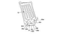
図1〜図3に示す本発明の好ましい一実施形態に係るシート材容器10は、例えば内容液として液体洗剤を内部に収容して、好ましくはスタンディングパウチに類似する袋状の容器製品11として製品化される。本実施形態のシート材容器10は、可撓性を有する、柔軟性に富んだ合成樹脂製の薄肉のシート材20を用いて形成される。また、本実施形態のシート材容器10は、胴部12を構成する胴部シート12(12a、12a)、及び底部25を構成する底面シート12bを備え、胴部シート12a、底面シート12bの、複数のフィルム層を積層したシート材のフィルム層の層間に、充填材が封入されて形成された、好ましくは膨出状の充填材封入部16a,16bが設けられている。充填材封入部16bを底面シート12bに設けることによって、載置面に対向して配置される底部25を効果的に補強し、落下強度を高め、あるいは内容物の量が少ない場合であってもシート材容器10の立体保持性を高め、充填材封入部16bにより容器を自立させる載置部17の剛性を高めて、自立安定性を向上させることができる。さらに、充填材封入部16aを胴部シート12aに設けることによって、底面シート12bに設けられている充填材封入部16bとの併用により、内容物の量が少ない場合であっても、胴部12と底部25に囲まれる収容部12の立体保持性をさらに高め、胴部12を把持した場合の圧縮強度に対しても一定の弾力性や剛性をもたせることが可能となり、さらにシート材容器10の自立安定性を向上することができる。 The
そして、本実施形態のシート材容器10は、複数のフィルム層20a,20b,20c(図4(a)参照)を有するシート材20で構成されている、胴部11と、載置面に対向して配置される底部25とを備える容器であって、胴部11を構成している胴部シート12aは周縁部分にシート材同士が接合されている接合部14を備え、底部25を構成している底面シート12bは、複数のフィルム層20a,20b,20cの層間に非接着領域21が設けられており、非接着領域21に充填材が封入されることで、底部充填材封入部16bが形成されている。 The
すなわち、本実施形態のシート材容器10は、複数のフィルム層20a,20b,20c(図4(a)参照)を積層して形成されたシート材20を用いて形成される、袋状の容器であって、内側に内容液等の内容物を収容できる収容部を形成する、胴部シート12aと、胴部シート12aの周縁部分にシート材同士が接合されて形成されている接合部14と、底面シート12bとを備えている。底面シート12bは、好ましくは折り畳み用の折り目13cが形成されており、折り畳み用の折り目13cを介して平坦に重ねて折り畳まれた状態から、例えば収容部12の内側に内容物が収容されたり、或いは非接着領域21に充填材が封入されて底部充填材封入部16bが形成されることで展開して、載置面に線接触又は面接触して載置されることで容器10を自立させる、載置部17を形成するようになっている。少なくとも底面シート12bにおける、シート材20を構成する複数のフィルム層20a,20b,20cの層間に非接着領域21が設けられており、この非接着領域21に充填材として好ましくは空気や水等の流体が封入されて、図3に示すように、非接着領域21が封入された充填材によって膨らんだことによる、補強用の底部充填材封入部16bが形成されている。 That is, the
また、本実施形態では、収容部12は、図1〜図3に示すように、前後一対の胴部シート12aを備えており、これらの胴部シート12aは、シート材20を構成する複数のフィルム層20a,20b,20cの層間に設けられた非接着領域21に、充填材として好ましくは空気や水等の流体が封入されて、正面部充填材封入部16aが形成されている。正面部充填材封入部16aを形成するための胴部シート12aに設けられた非接着領域21は、底面シート12bにおける底部充填材封入部16bを形成するための非接着領域21と連通している。 Further, in the present embodiment, as shown in FIGS. 1 to 3, the
さらに、本実施形態では、シート材容器10は、シート材20による、前後一対の正面部シート13a,13aの周縁部分と、折り畳み用の折り目13cを介して前後一対の正面部シート13a,13aの内側に二つ折りに折込み可能な、底面マチ部シート13bの周縁部分とを、接合部14として互いに例えばヒートシールすることによって、袋状の容器として形成されている。前後一対の正面部シート13a,13aの、接合部14によって囲まれる部分が、収容部シート部12の前後一対の胴部シート12a,12aとなっており、底面マチ部シート13bの、接合部14によって囲まれる部分が、収容部シート部12の底面シート12bとなっている。 Further, in the present embodiment, the
ここで、本明細書でヒートシールとは、加熱されたヒートシールバーやロールによる熱封緘に限定されず、超音波シール、高周波シール等、接合部を熱封緘することができる全ての熱封緘を意味する。 Here, the heat seal in the present specification is not limited to heat seal by a heated heat seal bar or roll, but includes all heat seals such as ultrasonic seals and high frequency seals that can heat seal joints. means.
また、接合部14は、シート材20の裏面同士をヒートシールして形成されること以外に、例えばシート材20同士を接着剤により接着して形成することができる。 Further, the
本実施形態では、胴部のシート(胴部シート)12a,12a及び底面シート12bに設けられた非接着領域21は、図4に示すように、後述する最内層のシーラントフィルム層20cと、中間層のバリアフィルム層20bとの層間に形成されている。これらのフィルム層20b,20cの層間は、ラミネート接着剤(図示せず)を用いて接着されており、非接着領域21を含む塗布パターンで、ラミネート接着剤をシーラントフィルム層20c又はバリアフィルム層20bの表面に塗布することで、非接着領域21を、所望の形状に形成できる。 In the present embodiment, the
また、非接着領域21は、複数のフィルム層20a,20b,20cの層間をラミネート接着剤を用いて接着する際に、非接着領域21に対応する部分の少なくとも一方のフィルム層20a,20b,20cの表面に、非接着処理を施しておくことで、非接着領域21を所望の形状に形成することもできる。非接着処理は、非接着領域21に対応する部分に、非接着剤(糊殺し剤)を塗布して糊殺し状態とすることによって、容易に行なうことができる。糊殺し剤としては、感圧接着剤層の接着を防止できるものであれば、如何なるものも使用することかできる。例えばオフセット印刷、フレキソ印刷、レタープレス印刷(凸版印刷)のそれぞれに使用する印刷用インキ、メジウムインキ、糊殺し専用インキ等を、好ましく用いることができる。また、熱硬化型や紫外線硬化型のインキを好ましく用いることができる。なお、本明細書において、接着には粘着も含まれるものとする。 Further, the
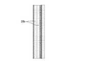
本実施形態では、前後一対の正面部シート13a,13a、及び底面マチ部シート13bを構成するシート材20は、図4(a)に示すように、例えば最外層の基材フィルム層20aと、最内層のシーラントフィルム層20cと、これらの間に挟まれる中間層のバリアフィルム層20bとを積層した、3層構造のシート材となっている。非接着領域21は、最内層のシーラントフィルム層20cと、中間層のバリアフィルム層20bとの間の層間に形成されている。 In the present embodiment, as shown in FIG. 4A, the
前後一対の正面部シート13a,13a、及び底面マチ部シート13bを構成するシート材20は、図4(b)に示すように、中間層のバリアフィルム層20bを複数層で形成することもできる。中間層の複数層のバリアフィルム層20bの層間に、非接着領域21を形成することもできる。このような層構成を備えるシート材20として、例えば外側層からONy15μm/接着層/VM−PET12μm/(非接着領域)/接着層/VM−ONy15μm/接着層/LLDPE40μm(最内層)からなるものを挙げることができる。なお、ONyは延伸ナイロンを意味し、VM−ONyはアルミ蒸着延伸ナイロン等の金属蒸着された延伸ナイロンを意味し、VM−PETはアルミ蒸着ポリエチレンテレフタレート等の金属蒸着されたポリエチレンテレフタレートを意味する。 As shown in FIG. 4B, the
また、前後一対の正面部シート13a,13a、及び底面マチ部シート13bを構成するシート材20は、図4(c)に示すように、基材フィルム20aと中間層バリアフィルム層20bとの層間に、非接着領域21が形成されていても良い。このような層構成を備えるシート材20として、例えば外側層から無機蒸着PET12μm/(非接着領域)/接着層/VM−PET12μm/接着層/LLDPE40μm(最内層)からなるものを挙げることができる。なお、無機蒸着PETは例えばアルミナや酸化ケイ素等が蒸着されたPETである。 Further, as shown in FIG. 4C, the
さらに、前後一対の正面部シート13a,13a、及び底面マチ部シート13bを構成するシート材20は、フィルム間の接着の手段が熱融着、超音波融着等の融着を含む場合には、シート材20は、例えば、図4(d)に示すように、中間層のバリアフィルム層20bが、2層のシーラント層を有し、これらの2層のシーラント層の間に非接着領域21が形成されるようにしても良い。このような層構成を備えるシート材20として、例えば外側層からONy15μm/接着層/VM−PET12μm/接着層/LLDPE40μm/(非接着領域)/LLDPE40μm/接着層/VM−PET12μm/接着層/ONy15μm/接着層/LLDPE40μm(最内層)からなるものを挙げることができる。 Further, in the
以下、接着剤による接着については、図4(a)にしたがって、最内層のシーラントフィルム層20cと中間層のバリアフィルム層20bとの間の層間に非接着領域21を形成する場合を例に説明するが、非接着領域21は、上述のように、中間層のバリアフィルム層20bの層間に設けてもよいし、バリアフィルム層20bと基材フィルム層20aとの層間に設けてもよい。 Hereinafter, adhesion by an adhesive will be described by taking as an example a case where a
最外層の基材フィルム層20aは、例えば、ポリエチレンテレフタレート(PET)、ポリエチレンナフタレ−ト(PEN)、ポリブチレンテレフタレート(PBT)などのポリエステル、ポリエチレン(PE)、ポリプロピレン(PP)、ポリスチレン(PS)などのポリオレフィン、ナイロン−6、ナイロン−66などのポリアミド(PA)等の延伸又は無延伸フィルムを使用して形成することができる。 The outermost
基材フィルム層20aの厚さは、例えば3〜200μmであることが好ましく、3〜100μmであることがより好ましく、6〜30μmであることがさらに好ましい。 The thickness of the
最内層のシーラントフィルム層20cは、例えば、低密度ポリエチレン樹脂(LDPE)、中密度ポリエチレン樹脂(MDPE)、高密度ポリエチレン樹脂(HDPE)、直鎖状低密度ポリエチレン樹脂(L−LDPE)、ポリプロピレン樹脂(PP)等を使用して形成することができる。 The innermost
最内層のシーラントフィルム層20cの厚さは、例えば15〜200μmであることが好ましく、20〜180μmであることがより好ましく、30〜170μmであることがさらに好ましい。 The thickness of the innermost
中間層のバリアフィルム層20bは、例えば、アルミ蒸着フィルム、エチレン−ビニルアルコール共重合体(EVOH)、アルミニウム箔、ポリ塩化ビニリデン(PVDC)、PVDCコートフィルム、セラミックス蒸着フィルム等を使用して形成することができる。中間層のバリアフィルム層20bは、シート材20の非接着領域21の周囲の接着部を形成する手段が融着である場合には、さらに低密度ポリエチレン樹脂(LDPE)層、直鎖状低密度ポリエチレン樹脂(L−LDPE)層から選ばれるシーラント層を2層設けることが好ましい。 The
バリアフィルム層20bの厚さは、例えば3〜100μmであることが好ましく、3〜50μmであることがより好ましく、5〜25μmであることがさらに好ましい。中間層のバリアフィルム層20bは、シート材20の非接着領域21をバリアフィルム層20b内に設ける場合には、バリアフィルム層20bの厚さは、例えば80μm〜200μmであることが好ましく、100〜180μmであることが好ましく、100〜160μmであることが好ましい。 The thickness of the
これらのフィルム層20a,20b,20cは、例えば公知のラミネート接着剤を用いて、例えばドライラミネーション、ノンソルベントドライラミネーション、ホットメルトラミネーション等の公知のラミネーション方法によって、一体として積層した状態で容易に接着されて、シート材20を形成することができる。 These film layers 20a, 20b, and 20c are easily bonded together in a laminated state by using a known lamination adhesive, for example, by a known lamination method such as dry lamination, non-solvent dry lamination, or hot melt lamination. The
なお、2枚のフィルムを熱融着する際に非接着領域を形成する場合、内側および外側のフィルムのシーラント層同士を向かい合わせ、これらのフィルムを凹凸のついた金型でプレスすることによって、非接着領域を形成することができる(凸部によって接着部が、凹部によって非接着領域が形成される)。非接着領域の形状に切り取ったシーラントに溶着されないシート等(PETなど)を、内側と外側のフィルムの間に挟み、平面形状の金型でプレスすることによって、非接着領域を形成することも可能である。 When forming a non-adhesive region when two films are heat-sealed, the sealant layers of the inner and outer films are faced to each other, and these films are pressed with an uneven mold. A non-adhesive region can be formed (convex forms an adhesive portion and concave portions form a non-adhesive region). It is also possible to form a non-adhesive region by sandwiching a sheet or the like (PET, etc.) that is not welded to the sealant cut into the shape of the non-adhesive region between the inner and outer films and pressing it with a flat mold. Is.
また、非接着領域21以外の接着領域の接着は、接着剤による接着以外に、熱融着、あるいは超音波やレーザーを用いた融着、圧着等も含まれる。接着方法は、層構成を薄くする観点及び塗布パターンの自由度の観点からは、接着剤による接着が好ましく、接着剤の材質によらず一定の強度を得る観点からは、融着が好ましい。 Further, the adhesion of the adhesive region other than the
また、本実施形態では、前後一対の正面部シート13a,13a、及び底面マチ部シート13bにおける、最内層のシーラントフィルム層20cと、中間層のバリアフィルム層20bとの間の接着は、上述のように、非接着領域21を含む所定の塗布パターンで、ラミネート接着剤をシーラントフィルム層20cやバリアフィルム層20bの表面に塗布することにより行われる。これによって、一対の正面部シート13a,13aにおける、周縁部分の接合部14によって囲まれる前後一対の胴部シート12a,12aの各々には、図2(a)及び図2(b)に示すように、横方向封入部16c、縦方向封入部16d、及び底辺部湾曲封入部16eを含む補強用の正面部充填材封入部16aを形成するための非接着領域21が、これらのリブ状の封入部16c,16d,16eを連通させた状態で、シーラントフィルム層20cとバリアフィルム層20bとの間の層間に形成される。また、底面マチ部シート13bにおける、周縁部分の接合部14によって囲まれる底面シート部12bには、図3に示すように、交差封入部16g及び連通封入部16hを含む補強用の底部充填材封入部16bを形成するための非接着領域21が、接続部充填材封入部16fを介して前後一対の胴部シート12a,12aの正面部充填材封入部16aと各々連通した状態で、シーラントフィルム層20cとバリアフィルム層20bとの間の層間に形成される。 Further, in the present embodiment, the adhesion between the innermost
なお、本実施形態では、非接着領域21は、最内層のシーラントフィルム層20cと、中間層のバリアフィルム層20bとの間の層間に形成されていることから、前後一対の胴部シート12a,12aに設けられた正面部充填材封入部16aと、底面シート部12bに設けられた底部充填材封入部16bとを各々連通する接続部充填材封入部16fを、シート材容器10の底辺部分に設けられた接合部14を横断させた状態で、容易に設けることができる。 In the present embodiment, since the
さらに、本実施形態では、シート材容器10の上辺部分の接合部14に開口して、非接着領域21の内部に充填材を供給するための外部連通口22が設けられている(図1、図2(a)、図2(b)、図3、図5参照)。外部連通口22は、前後一対の正面部シート13a,13aのうちの、正面側の一方の正面部シート13aの上辺部分の接合部14に開口して形成されている。外部連通口22は、例えば当該外部連通口22の内側壁面を覆って、シール接合片23を接着しておくことで、流体を注入した後に容易に封止できるようになっている。すなわち、外部連通口22は、対向する一方の内壁面が、シーラントフィルム層20cによる壁面となっており、他方の内壁面が、バリアフィルム層20bによる壁面となっていることから(図4参照)、そのままの状態では、非接着領域21に充填材を充填した後に、ヒートシールによって当該外部連通口22を封止することが困難である。このため、バリアフィルム層20bによる他方の内壁面を覆って、一方の内壁面側の面がシーラントフィルム層となっているシール接合片を接着しておくことで、充填材を充填した後に、外部連通口22が設けられた上辺部分をヒートシールすることによって、外部連通口22を容易に封止することが可能になる。シール接合片23は、外部連通口22から上方にはみ出した状態で設けておくことができ、はみ出した部分は、ヒートシールすることによって外部連通口22を封止した後に、除去される。シール接合片23のはみ出した部分は、除去することなくそのまま残しておいても良い。 Further, in the present embodiment, an
また、外部連通口22における、接着したシール接合片23と、シーラントフィルム層20cによる一方の内壁面との間に、好ましくはヒートシールすることが可能な樹脂(例えばポリエチレン樹脂)からなる逆止弁(図示せず)を、密着させた状態で挟み込んでおくこともできる。逆止弁を挟み込んでおくことで、外部連通口22が封止されるまでの間、充填した充填材が、非接着領域21から外部連通口22を介して漏れ出るのを、効果的に回避することが可能になる。逆止弁は、これを挟み込んだ状態のままヒートシールすることにより、押し潰されるように変形して充填材の流路を閉塞することで、外部連通口22を容易に封止することができる。 Further, a check valve made of a resin (for example, polyethylene resin) capable of heat-sealing preferably between the bonded seal
なお、外部連通口22は、ヒートシールによって封緘(封止)できる他、例えばビーチボール用の空気弁などをシール接合片23の代わりに用いて封緘することもできる。また、外部連通口22は、接着剤によって封緘することもできる。 The
ここで、本実施形態では、非接着領域21に充填されて充填材封入部16a,16b,16f(正面部充填材封入部16a、底部充填材封入部16b、及び接続部充填材封入部16f)を形成する充填材としては、窒素、空気等の気体、水、水溶液、油剤から選ばれる流体を好ましく用いることができる。また、粉粒体、樹脂、発泡材等を用いることもできる。発泡材としては、UV硬化性発泡ガスケット等の、紫外線を照射することにより発泡する材料を用いることもできる。UV硬化性発泡ガスケットは、非接着領域21に封入された後に、容器10の外側から紫外線を照射することにより、発泡すると共に硬化して、膨らんだ状態を保持することで、好ましくは様々な形状の膨出状、あるいはリブ状の充填材封入部16a,16b,16fを形成する。なお、上記の流体、粉粒体等を適宜混合して非接着領域21に充填することにより、充填材封入部16a,16b,16fを形成することもできる。これらの充填材としては、軽量化の観点から窒素、空気等の気体がより好ましい。 Here, in the present embodiment, the
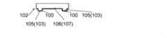
本実施形態のシート材容器10を製造するには、例えば最内層のシーラントフィルム層20cと、中間層のバリアフィルム層20bとの間の層間を、非接着領域21を含む所定の塗布パターンで塗布したラミネート接着剤を介して接着することで、複数のシート材容器10に対応する非接着領域21が原反製造装置の流れ方向(Machine Direction)に連設して配置された、シート材20の原反を形成する。しかる後に、形成したシート材20の原反を、製袋装置において重ね合わせた一対の正面部シート13a,13aの原反部分の間の底部内側に、底面マチ部シート13bの原反部分を、断面がM字形状となるように折り込んだ状態で、製袋装置の流れ方向に送り出す。また、送り出されたシート材20の原反の、個々のシート材容器10と対応する部分において、個々のシート材容器10のシート13a,13a,13bの周縁部分を、内容液の注入口となる部分を残して例えばヒートシールにより接合する。さらに、ヒートシールされた原反を、連設する個々のシート材容器10の間の接合部14で切断する。これによって、図5に示すような、非接着領域21に充填材が封入される前のシート材容器10が、容器用シート材料18として、平坦に畳まれた状態で、矩形(略矩形を含む)の正面形状を備えるように形成される。 In order to manufacture the
したがって、本実施形態のシート材容器10に使用され、複数のフィルム層20a,20b,20cを有するシート材20を用いて形成される容器用シート材料18は、非接着領域21が少なくとも底面シート12b(本実施形態では、一対の胴部シート12a,12a及び底面シート12b)に設けられたシート材20の原反を形成する工程、原反の個々の容器用シート材料18と対応する部分の周縁部分を接合する工程、及び接合された原反を個々の容器用シート材料18になるように所定寸法に切断する工程を含む製造方法によって、製造することができる。 Therefore, in the
製造された容器用シート材料18には、シート材20を構成する複数のフィルム層20a,20b,20cの層間に非接着領域21が設けられており、この非接着領域21に充填材が封入されることで、当該非接着領域21による好ましくは様々な形状の膨出状、あるいはリブ状の充填材封入部16a,16b,16fが形成される。これによって、本実施形態のシート材容器10が製造される。 The manufactured
したがって、本実施形態のシート材容器10は、非接着領域21が少なくとも底面シート12b(本実施形態では、一対の胴部シート12a,12a及び底面シート12b)に設けられたシート材20の原反を形成する工程、原反の個々のシート材容器10と対応する部分の周縁部分を接合する工程、接合された原反を所定寸法に切断する工程、及び非接着領域21に充填材を封入して、補強用の底部充填材封入部16b(本実施形態では、正面部充填材封入部16a、底部充填材封入部16b、及び接続部充填材封入部16f)を形成する工程を含む製造方法によって、製造することができる。 Therefore, in the
本実施形態では、上述の構成を備えるシート材容器10は、非接着領域21に充填材が封入される前の容器用シート材料18として、図5に示す平坦に畳まれた状態で、例えば製品製造工場に搬入される。これによって、内容液をはじめとする内容物が充填される前の多数の容器用シート材料18を、嵩張らせることなく、搬送容積を小さくした状態で、効率良く搬入することが可能になる。製品製造工場では、シート材容器10の収容部に内容物を収容する工程と、非接着領域21に充填材を封入して補強用の底部充填材封入部16b(本実施形態では、正面部充填材封入部16a、底部充填材封入部16b、及び接続部充填材封入部16f)を形成する工程とを含む製造方法によって、袋状の容器製品11を容易に製造することができる。 In the present embodiment, the
容器製品11を製造するには、例えば搬入された容器用シート材料18を、平坦に畳まれた状態から解放すると共に、外部連通口22を介して、非接着領域21に充填材を充填し、封入することによって、好ましくは様々な形状の膨出状、あるいはリブ状の充填材封入部16a,16b,16fを形成することで、底面マチ部シート13bを底部とする立体形状となるようにシート材容器10を形成する。しかる後に、一対の正面部シート13a,13aの上辺部分の、ヒートシールすることなく残した部分を注入口として、内容液である液体洗剤を収容部12内に注入する。さらに、収容部に液体洗剤を注入した後に、注入口の部分を好ましくはヒートシールによって接合すると共に、外部連通口22から上方にはみ出した部分のシール接合片23を、必要に応じて切断して除去する。これらによって、図1に示すような、シート材容器10の内部に液体洗剤を収容した容器製品11が、底面シート12bに形成された載置部17(図3参照)を載置面に載置することで自立可能な状態で、製品化される。 In order to manufacture the
容器製品11は、注入口を介して容器用シート材料18の内部に液体洗剤を注入した後に、外部連通口22を介して非接着領域21に充填材を封入することで、充填材封入部16を形成してシート材容器10とすることによって、容器製品11を製品化することもできる。注入口を介して容器用シート材料18の内部に液体洗剤を注入するのと並行して、外部連通口22を介して非接着領域21に充填材を封入することで、充填材封入部16を形成してシート材容器10とすることによって、容器製品11を製品化することもできる。また、上述のように、外部連通口22を介して非接着領域21に充填材を封入することで充填材封入部16を形成してシート材容器10とした後に、注入口を介してシート材容器10の内部に液体洗剤を注入することによって、シート材容器10に内容液を充填する作業を、より安定した状態で行うことが可能になる。 In the
本実施形態のシート材容器10を用いて形成された容器製品11では、内容液が収容された収容部を内側に形成している胴部シート12a、即ち胴部12の、正面側及び背面側の前後一対の胴部シート12a,12aに、各々、好ましくはリブ状の補強用の正面部充填材封入部16aが、細長い線状に延設して設けられている。また、収容部12を構成する底面シート12bにもまた、好ましくは膨出状、例えばリブ状の補強用の底部充填材封入部16bが、細長い線状に延設して設けられている(図3参照)。これらの胴部シート12a,12aに設けられた正面部充填材封入部16aと、底面シート12bに設けられた底部充填材封入部16bとは、シート材容器10の底辺部分の接合部14に設けられた接続部充填材封入部16fを介して、互いに連通している。 In the
ここで、細長い線状に延設する充填材封入部16a,16b,16fは、例えば3〜50mm程度の幅で連続して設けられる封入部であり、直線状に連続して延設する封入部の他、曲線状、波形形状、クランク形状等の、その他の種々の細長い形状に連続して延設する封入部も含まれる。また、線状の充填材封入部16a,16b,16fの任意の箇所に、必要に応じて例えば充填材封入部16a,16b,16fの線状部分の横幅よりも幅の広い平面をもった形状や、幅が広くドーム状に隆起した円形状、あるいは球形状等の充填材封入部24を単独でまたは適宜組み合わせて、介在させて設けることもできる(図13参照)。なお、シート材容器10は、充填材が封入され、充填材封入部16a,16b,16fが膨出した状態、あるいは内容物が十分に収容された状態で立体形状を成す。立体形状をなす場合の胴部シート12a、12aに形成される横断面における角部に相当する領域に、充填材封入部16aによる膨出領域を備えることが好ましい。胴部シート12a、12aに形成される前記横断面における角部は、胴部シート12a、12aにおいて底部側から起立する稜線、あるいは湾曲した角部により形成され、かかる稜線あるは角部に相当する領域に充填材封入部16aが形成されることが、落下強度、保形性の観点から好ましい。 Here, the
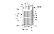
本実施形態では、前後一対の胴部シート12a,12aの各々に設けられた補強用の正面部充填材封入部16aは、図2(a)、(b)に示すように、横方向に延設して間隔をおいて平行に並べて配置された2本の横方向封入部16cと、縦方向に延設して間隔をおいて平行に並べて配置された5本の縦方向封入部16dと、胴部シート12a,12aの底辺部に沿って湾曲した形状に延設して配置された底辺部湾曲封入部16eとを含んで構成されている。これらの封入部16c、16d、16eは、連通した状態で設けられている。5本の縦方向封入部16dのうち、両側部の一対の縦方向封入部16dによって挟まれた3本の縦方向封入部16dは、その下端部が、底辺部湾曲封入部16eに連続(連通)することなく、底辺部湾曲封入部16eと離間した状態で設けられている。このように離間した部分を有していると、容器製品とした際に、内容物の重量によって離間した部分が折れ曲がり、容器製品の底面が更に広がり易くなることで、自立安定性が更に向上する。 In the present embodiment, the reinforcing front
また、前後一対の胴部シート12a,12aのうちの正面側の胴部シート12aには、例えば右から2番目の縦方向封入部16dの上端部から上方に延設させて、連通口接続封入部16iが形成されている。この連通口接続封入部16iの上方部分の、正面部シート13aの上辺部の接合部14と重なる部分が、外部連通口22となっている。この外部連通口22は、上述のように、非接着領域21の内部に充填材として例えば空気や水等の流体を注入して、充填材封入部16a,16b,16fを膨らませた後に、好ましくはヒートシールにより封止されて、充填材封入部16a,16b,16fの内部に流体を容易に封入することが可能になる。外部連通口22の封止は、ヒートシールの他、例えば接着剤、逆止弁等を用いたり、該外部連通口22の折り込み等によって行うこともできる。 Further, of the pair of front and
ここで、胴部シート12a,12aに設けられた補強用の正面部充填材封入部16aが、横方向に延設して形成された横方向封入部16cを含んでいることにより、容器製品11に負荷される横方向の荷重に対する強度や剛性を、効果的に高めることが可能になると共に、胴部12の把持性を向上させることが可能になる。また、縦方向に延設して形成された縦方向封入部16dを含んでいることにより、容器製品11に負荷される縦方向の荷重に対する強度や剛性を、効果的に高めることが可能になると共に、胴部12の把持性を向上させることが可能になる。補強用の正面部充填材封入部16aが、横方向に延設して形成された横方向封入部16c及び縦方向に延設して形成された縦方向封入部16dを含んでいることにより、これらの相乗効果によって、容器製品11に負荷される荷重に対する強度や剛性を、さらに効果的に高めることが可能になると共に、胴部12の把持性をさらに向上させることが可能になる。また、非接着領域21の内部に流体を注入した後に、好ましくはヒ−トシールによって封止される外部連通口22が、正面側の正面部シート13aにおける、上辺部の接合部14と重なる部分に設けられていることにより、容器製品11の製造ラインにおいて、外部連通口22を容易に封止して、充填材を封入することが可能になる。 Here, the front filling
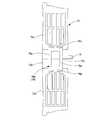
そして、本実施形態では、上述のように、収容部は、底面シート12bを備えており、底面シート12bは、折り畳み用の折り目13cを介して平坦に重ねて折り畳まれた状態から、図3に示すように、例えば収容部に内容物が収容されたり、或いは非接着領域21に充填材が封入されて底部充填材封入部16bが形成されたりすることで展開して、載置部17を形成するようになっている。また、底面シート12bにおける、シート材20を構成する複数のフィルム層20a,20b,20cの層間に、非接着領域21が設けられており(図4参照)、この非接着領域21に充填材が封入されて、非接着領域21による底部充填材封入部16bが形成されるようになっている。 Then, in the present embodiment, as described above, the accommodating portion includes the
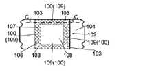
すなわち、本実施形態では、収容部の底部25を構成する底面シート12bには、補強用の底部充填材封入部16bとして、3本の交差封入部16gと、一対の連通リブ部16hとを含んで構成される充填材封入部が設けられている。交差封入部16gは、一対の正面部シート13a,13aの底部内側に断面がM字形状となるように折り込まれた底面マチ部シート13bの、折り畳み用の折り目13cと略垂直に交差して配置されている。連通リブ部16hは、3本の交差リブ部16gの両端部を各々互いに連通させるように配置されている。 That is, in the present embodiment, the
底面シート12bに、底部充填材封入部16bが設けられていることにより、底面シート12bの強度や剛性を、効果的に高めることが可能になる。また、底部充填材封入部16bの交差封入部16gが、底面マチ部シート13bの折り目13cと略垂直に交差して配置されていることにより、交差封入部16gが膨らむことで、折り込まれた底面マチ部シート13bによる底面シート12bを、折り癖に抗して広がるようにスムーズに誘導することが可能になる。さらに、例えば非接着領域21に充填材が封入されて底部充填材封入部16bが形成されることで、底面シート12bが展開して、底面シート12bに形成された載置部17は、3本の交差封入部16gと、一対の連通リブ部16hとによる、相当の大きさの矩形枠状の底部充填材封入部16bを脚部として、載置面に載置することが可能になる。これによって、底面シート12bを載置面に接触させる部分の形状を安定させて、袋状の容器製品11をさらに安定した状態で自立させることが可能になる(図1参照)。 Since the
本実施形態によれば、補強用の充填材封入部16a,16b,16fの形状や配設位置等の選択の自由度を向上させて、容器10の任意の位置に補強用の充填材封入部16a,16b,16fを設けることを可能にすることで、特に底面シート12bを底部充填材封入部16bによって効果的に補強して、載置部17による自立安定性を向上させたり、載置部17の剛性を高めたりすることが可能になる。 According to the present embodiment, the degree of freedom in selecting the shape, arrangement position, etc. of the reinforcing
また、本実施形態によれば、シート材20を構成する複数のフィルム層20a,20b,20cの層間に非接着領域21が設けられており、この非接着領域21に充填材として例えば空気や水等の流体を封入することで、図1〜図3に示すように、封入された充填材によって非接着領域21が膨らんだことによる補強用の充填材封入部16a,16b,16fを、シート材20の複数のフィルム層20a,20b,20cの層間に容易に形成することができる。したがって、例えば複数のフィルム層20a,20b,20cの層間を接着するラミネート接着剤の塗布パターンを、任意の形状や配置で自由に設計することによって、接合部14だけでなく、特に変形し易い収容部を構成する胴部シート12a,12aや底面シート12bにも、所望の形状や配置で非接着領域21を容易に設けることができる。これらの非接着領域21に充填材を封入して充填材封入部16a,16b,16fを所望の形状や配置で形成することによって、シート材容器10及び容器製品11の所望の部分を、効率良く効果的に補強したり、剛性を向上させたりすることが可能になる。 Further, according to the present embodiment, the
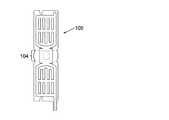
図6(a)及び図6(b)は、本発明の他の実施形態のシート材容器60及び容器製品61を説明するものである。図6(a)及び図6(b)のシート材容器60及び容器製品61は、上記実施形態のシート材容器10及び容器製品11と同様の構成を備えているが、その一方で、底部充填材封入部66b及び外部連通口62の形状や配置が、上記実施形態の底部充填材封入部16b及び外部連通口22の形状や配置と相違している。 6 (a) and 6 (b) explain the
なお、後述する図6(a)〜図12のシート材容器及び容器製品は、底部充填材封入部66b、76b、86b、96bが、胴部12において対向する正面側から背面側に連続する部分を備えており、好ましくは底部充填材封入部66b、76b、86b、96bを形成している非接着領域によって囲まれた、充填材が封入されていない充填材非封入部を備えている。特に、図7(a)、図8(a)、図9(a)のシート材容器70,89,90では、底面シート12bの中央に複数のフィルム層の層間が接着されている接着領域が設けられており、中央の接着領域を囲んで非接着領域79、89、99bが設けられている。さらに好ましくは、底部充填材封入部66b、76b、86b、96bは、載置面に載置される載置部(載置される領域)の周縁に沿って形成されており、より好ましくは周縁に沿って連続して形成されている。底部充填材封入部66b、76b、86b、96bをこのように形成することで、底部の剛性をより高めるとともに、底部による自立安定性、立体形状保持性を向上することができる。 In the sheet material containers and container products of FIGS. 6A to 12 described later, the bottom
また、図6(a)〜図12のシート材容器及び容器製品は、底部充填材封入部66b、76b、86b、96bが、胴部シートと底面シートの間の境界領域に設けられていることが好ましい。即ち、胴部シートと底面シートとの間の境界領域は、シート材容器の角部に該当し、かかる角部において充填材封入部66b、76b、86b、96bが設けられていることにより、シート材容器の脚部が充填材封入部66b、76b、86b、96bによって形成されて、落下強度、自立安定性をさらに向上することができる。 Further, in the sheet material containers and container products of FIGS. 6A to 12, the bottom
ここで、胴部正面シート12aと底面シート12bの間の境界領域は、ヒートシールによる接合部となっている必要は必ずしも無く、正面シート12aと底面シート12は、例えば別フィルムではなく1枚のフィルムを折りたたんで製袋することにより、ヒートシールによる接合部を介することなく形成することができる。 Here, the boundary region between the
図6(a)及び図6(b)のシート材容器60及び容器製品61では、図6(c)の、シート材容器60に使用される容器用シート材料68の展開正面図にも示すように、非接着領域69に充填材を封入して形成される底部充填材封入部66bは、3本の交差封入部66gと、一対の連通リブ部66hとを含んで構成されている。3本の交差封入部66gは、底面シート62bにおいて、底面マチ部シート63bに設けられた折り畳み用の折り目63cと略垂直に交差して、互いに平行に配置されて設けられている。また、これらの3本の交差封入部66gの両端部を各々互いに連通させる一対の連通リブ部66hは、前後一対の正面部シート63a,63aの両側縁の底辺側部分と、底面マチ部シート63bの両側縁とを例えばヒートシールすることによって接合した接合部64に配置されて設けられている。さらに、外部連通口62は、底部充填材封入部66bの交差封入部66gから、底面マチ部シート63bの折り目63cの片側に沿って延設して、底面マチ部シート63bの側辺部から外側に突出した状態で配置されて設けられている。 In the
図6(a)及び図6(b)のシート材容器60及び容器製品61によっても、例えば非接着領域69に充填材が封入されて底部充填材封入部66bが形成されたり、収容部に内容物が収容されたりすることで底面シート62bが展開して、底面シート62bに形成された載置部67は、相当の大きさの矩形枠状の底部充填材封入部66bを脚部として、載置面に載置することができるので、上記実施形態のシート材容器10や容器製品11と、同様の作用効果が奏される。 Also in the
また、図6(a)及び図6(b)のシート材容器60及び容器製品61によれば、底面部充填材封入部66bの連通リブ部66hが、一対の正面部シート63a,63aの底辺部分と、底面マチ部シート63bの両側の周縁部分との接合部64に沿って、相当の長さで設けられている。これによって、これらの両側の連通リブ部66hを、載置面に直接載置させることで、シート材容器60が、収容部に内容液が収容される前の空容器の状態であっても、自立した状態で安定して載置面に載置することが可能になる。さらに、外部連通口62が、底部充填材封入部66bから延設して設けられており、且つ一対の正面部シート63a,63aの底辺部分と、底面マチ部シート63bの両側の周縁部分との接合部64に沿って、底部充填材封入部66bの連通リブ部66hが、相当の長さで設けられている。これによって、これら連通リブ部66hを、底部充填材封入部66bと正面部充填材封入部66aとの接続部として用いて、少ない圧力損失で、簡便な充填材の封入工程によって、底部充填材封入部66bと正面部充填材封入部66aの全体に、充填材をスムーズに行き渡らせて封入することが可能になる。 Further, according to the
図7(a)もまた、本発明の他の実施形態のシート材容器70及び容器製品71を説明するものである。図7(a)のシート材容器70及び容器製品71もまた、上記実施形態のシート材容器10及び容器製品11と同様の構成を備えているが、その一方で、底部充填材封入部76b及び外部連通口72の形状や配置が、上記実施形態の底部充填材封入部16b及び外部連通口22の形状や配置と相違している。 FIG. 7A also illustrates the
すなわち、図7(a)のシート材容器70及び容器製品71では、図7(b)の、シート材容器70に使用される容器用シート材料78の展開正面図にも示すように、非接着領域79に充填材を封入して形成される底部充填材封入部76bは、一対の交差封入部76gと、一対の連通リブ部76hとを含む、矩形枠形状を有するように形成されている。一対の交差封入部76gは、底面シート72bにおいて、底面マチ部シート73bの折り目73cと略垂直に交差して、互いに平行に配置されて設けられている。また、これらの交差封入部76gの両端部を各々互いに連通させる一対の連通リブ部76hは、前後一対の正面部シート73a,73aの両側縁の底辺側部分と、底面マチ部シート73bの両側縁とを例えばヒートシールすることによって接合した、接合部74に配置されて設けられている。さらに、外部連通口72は、底部充填材封入部76bの交差封入部76gから、底面マチ部シート73bの折り目73cの片側に沿って延設して、底面マチ部シート73bの側辺部から外側に突出した状態で配置されて設けられている。 That is, in the
図7(a)のシート材容器70及び容器製品71によっても、例えば非接着領域79に充填材が封入されて底部充填材封入部76bが形成されたり、収容部に内容物が収容されることで底面シート72bが展開して、底面シート72bに形成された載置部77は、相当の大きさの矩形枠形状の底部充填材封入部76bを脚部として、載置面に載置することができるので、上記実施形態のシート材容器10や容器製品11と、同様の作用効果が奏される。 Also in the
また、図7(a)のシート材容器70及び容器製品71によれば、底部充填材封入部76bの連通リブ部76hが、一対の正面部シート73a,73aの両側縁の底辺側部分と、底面マチ部シート73bの両側縁との接合部74に沿って、相当の長さで設けられているので、上記他の実施形態のシート材容器60や容器製品61と、同様の作用効果が奏される。さらに、底部充填材封入部76bは、一対の交差封入部76gと、一対の連通リブ部76hとを含む矩形枠形状を有しているので、非接着領域79に充填材が封入されて底部充填材封入部76bが形成される際に、容易に底面シート部72bを押し広げることが可能になると共に、底部充填材封入部76bによる載置部77の脚部に、より大きな剛性を付与することが可能になる。 Further, according to the
図8(a)もまた、本発明の他の実施形態のシート材容器80及び容器製品81を説明するものである。図8(a)のシート材容器80及び容器製品81もまた、上記実施形態のシート材容器10及び容器製品11と同様の構成を備えているが、その一方で、底部充填材封入部86b及び外部連通口82の形状や配置が、上記実施形態の底部充填材封入部16b及び外部連通口22の形状や配置と相違している。 FIG. 8A also illustrates the
すなわち、図8(a)のシート材容器80及び容器製品81では、図8(b)の、シート材容器80に使用される容器用シート材料88の展開正面図にも示すように、非接着領域89に充填材を封入して形成される底部充填材封入部86bは、前後一対の正面部シート83a,83aの底辺部分と、底面マチ部シート83bの周縁部分とを接合した両側の一対の接合部84に、跨るように連続して配置されて設けられた、中央部分に非封入部86jを有する矩形状の面状封入部86kを含んで形成されている。面状封入部86kは、中央部分に円形の非封入部86jを有している。また、外部連通口82は、矩形状の面状封入部86kの側辺部から、底面マチ部シート83bの折り目83cの片側に沿って延設して、底面マチ部シート83bの側辺部から外側に突出した状態で配置されて設けられている。中央部分の非封入部86jは、複数のフィルム層の層間が接着された接着部からなることが好ましい。 That is, in the
図8(a)のシート材容器80及び容器製品81によっても、例えば非接着領域89に充填材が封入されて底部充填材封入部86bが形成されたり、収容部に内容物が収容されることで底面シート82bが展開して、底面シート82bに形成された載置部87は、相当の大きさの矩形状の面状封入部86kを脚部として、載置面に載置することができるので、上記実施形態のシート材容器10や容器製品11と、同様の作用効果が奏される。 Also in the
また、図8(a)のシート材容器80及び容器製品81によれば、矩形状の面状封入部86kの両側の縁部分が、一対の正面部シート83a,83aの底辺部分と、底面マチ部シート83bの両側の周縁部分との接合部84に沿って、相当の長さで設けられているので、上記他の実施形態のシート材容器60や容器製品61と、同様の作用効果が奏される。さらに、底部充填材封入部86bは、両側の一対の接合部84に跨るように連続して配置されて設けられた、矩形状の面状封入部86kを含んで形成されているので、底部充填材封入部86bを脚部として載置部87を載置面に載置した際の、自立安定性を向上させることが可能になる。 Further, according to the
図9(a)もまた、本発明の他の実施形態のシート材容器90及び容器製品91を説明するものである。図9(a)のシート材容器90及び容器製品91もまた、上記実施形態のシート材容器10及び容器製品11と同様の構成を備えているが、その一方で、底部充填材封入部96b及び外部連通口92の形状や配置が、上記実施形態の底部充填材封入部16b及び外部連通口22の形状や配置と相違している。 FIG. 9A also illustrates the
すなわち、図9(a)のシート材容器90及び容器製品91では、図9(b)の、シート材容器90に使用される容器用シート材料98の展開正面図にも示すように、非接着領域99に充填材を封入して形成される底部充填材封入部96bは、前後一対の正面部シート93a,93aの底辺部分と、底面マチ部シート93bの周縁部分とを接合した両側の一対の接合部94に、跨るように連続して配置されて設けられた、中央部分に非封入部96jを有する矩形状の面状封入部96kを含んで形成されている。面状封入部96kは、中央部分に、菱形形状の非封入部96jを有している。菱形形状の非封入部96jは、これの角部分を、矩形状の面状封入部96kの4方の辺部における、矩形状の4方の角部分から離間した中間部分に向けた状態で配置して、設けられている。また、外部連通口92は、矩形状の面状封入部96kの側辺部から、底面マチ部シート93bの折り目93cの片側に沿って延設して、底面マチ部シート93bの側辺部から外側に突出した状態で配置されて設けられている。 That is, in the
図9(a)のシート材容器90及び容器製品91によっても、例えば非接着領域99に充填材が封入されて底部充填材封入部96bが形成されたり、収容部に内容物が収容されることで底面シート部92bが展開して、底面シート部92bに形成された載置部97は、相当の大きさの矩形状の面状封入部96kを脚部として、載置面に載置することができるので、上記実施形態のシート材容器10や容器製品11と、同様の作用効果が奏される。 Also in the
また、図9(a)のシート材容器90及び容器製品91によれば、矩形状の面状封入部96kの両側の縁部分が、一対の正面部シート93a,93aの底辺部分と、底面マチ部シート93bの両側の周縁部分との接合部94に沿って、相当の長さで設けられているので、上記他の実施形態のシート材容器60や容器製品61と、同様の作用効果が奏される。さらに、底部充填材封入部96bは、両側の一対の接合部94に跨るように連続して配置されて設けられた、矩形状の面状封入部96kを含んで形成されているので、底部充填材封入部96bを脚部として載置部97を載置面に載置した際の、自立安定性を向上させることが可能になる。 Further, according to the
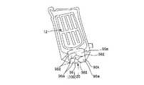
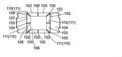
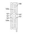
さらに、図9(a)のシート材容器90及び容器製品91によれば、矩形状の面状封入部96kの中央部分に設けられた非封入部96jは、好ましくは菱形形状を有していて、これの角部分を、矩形状の面状封入部96kの4方の辺部における、4方の角部分から離間した中間部分に向けた状態で配置して、設けられている。これによって、非接着領域99に充填材を封入することで底部充填材封入部96bが形成される際に、面状封入部96kには、矩形状の4方の角部分から離間した中間部分において、非封入部96jの角部分から矩形状の4方の辺部に向かう、凹状に折れ曲がった皺状部(シワ)96lが形成される。面状封入部96kの4方の角部分から離間した中間部分に、凹状に折れ曲がった皺状部(シワ)96lが形成されることで、この皺状部96lを挟んだ両側の部分の面状封入部96kが、凸部分(突出脚部)としてより下方に膨出するので、このような膨出した皺状部(シワ)96lの両側の凸部分を突出脚部96mとして、載置部97を載置面に載置することによって、さらに安定した状態で、シート材容器90や容器製品91を自立させることが可能になる。すなわち、非封入部96jは、面状封入部96kにシワが形成されるように誘導することで、脚部形成部100として機能している。 Further, according to the
上述のような、矩形状の面状封入部96kの4方の角部分から離間した中間部分に、凹状に折れ曲がった皺状部(シワ)96lを形成して、突出脚部96mを形成するための、面状封入部96kの4方の辺部の中間部分に角部分を向けた状態で配置して設けられる、脚部形成部100として機能する非封入部96jは、菱形形状を有していている必要は必ずしも無い。例えば図10に示すように、脚部形成部100として機能する非封入部96jは、4方の辺部が内側に向けて凹状に湾曲した、略菱形形状を有していても良い。また、脚部形成部100として機能する非封入部96jは、例えば図11に示すように、角部分が、矩形状の面状封入部96kの4方の辺部のうちの3方の辺部の中間部分に向けて配置された、三角形状を有していても良く、例えば図12に示すように、3方の辺部が内側に向けて凹状に湾曲した、略三角形状を有していても良い。 In order to form a wrinkled portion (wrinkle) 96l bent in a concave shape in an intermediate portion separated from the four corner portions of the rectangular
すなわち、図9(a)のシート材容器90は、複数のフィルム層20a,20b,20c(図4(a)参照)を有するシート材20で構成されている、胴部12と、載置面に対向して配置される底部25とを備える容器であって、胴部12を構成している胴部シート93aは、周縁部分にシート材同士が接合されている接合部94を備えており、底部25を構成している底面シート93bには、複数のフィルム層20a,20b,20cの層間に非接着領域99が設けられている。非接着領域99は、充填材が封入されていて、底部充填材封入部96bを形成しており、底部充填材封入部96bは、底面シート93の非封入部96jを囲んで環状に延設していると共に、載置面に載置されて容器10を自立させる少なくとも3箇所(本実施形態では、4箇所)の突出脚部96mを備える載置部97を形成しており、突出脚部96mは、載置部97の脚部形成部100として機能する非封入部96jによって、底部充填材封入部96bの他の部分(皺状部)よりも載置面側に突出している。 That is, the
載置面に載置される載置部97が、少なくとも3箇所の突出脚部96mを備えていることにより、シート材容器90を載置面に載置した際の、自立安定性をさらに向上させることが可能になる。 Since the mounting
ここで、載置部97に少なくとも3箇所の突出脚部96mを形成する脚部形成部100は、非封入部96jを囲んで環状に延設している底部充填材封入部96bの底面部分に、凹凸を生じさせて、載置面と好ましく点状に当接する少なくとも3箇所の突出脚部96mを、底部充填材封入部96bに形成させる手段を備える部分である。脚部形成部100は、上述のように、底部充填材封入部96bに複数のシワ96lが形成されるように誘導するシワ誘導部によるものの他、後述するように、底部充填材封入部96bに凹凸加工を施すことで設けられた、凸部自体又は凹部自体によるもの等であっても良い。 Here, the
また、底面シート93の非封入部96jを囲んで環状に延設している填材封入部96bは、全体が環状に連続する非接着領域99によって形成されている必要は必ずしも無く、例えば底面視して「C形」形状のように、その一部にフィルム層の層間が接着されている領域を含んでいても良い。 Further, the
本実施形態では、載置部97に少なくとも3箇所の突出脚部96mを形成する脚部形成部100は、図16(a)、(b)に示すように、底面視して、非接着領域99における他の部分よりも延設方向と垂直な方向の幅が大きくなっている、拡幅部分101を備えていても良い。非接着領域99に充填材が封入されている状態で、幅が大きくなっている拡幅部分101は、底部充填材封入部96bの他の部分よりも、断面積が大きくなるように膨出していることにより、非封入部96jを囲んで環状に延設している底部充填材封入部96bの他の部分よりも載置面側に突出していて、突出脚部96mを形成していることになる。拡幅部分101による突出脚部96mは、載置部97において、底面視して、できるだけ外側(底部の外縁方向)に配置される方が、自立安定性が向上することから、底部充填材封入部96bは、突出脚部96mができるだけ外側に配置されるように拡幅部分101が形成されるような形状とすることが好ましい(図16(b)参照)。 In the present embodiment, as shown in FIGS. 16A and 16B, the
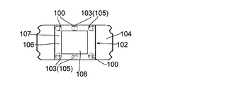
図17〜図20は、載置部102に少なくとも3箇所の突出脚部103を形成する脚部形成部100の、他の形態を例示するものである。なお、図17〜図20に示される、底面シート104の平面図は、図17(c)に示すシート材容器に使用される容器用シート材料105の展開正面図における、底面シート104の部分を拡大して示すものである。 17 to 20 exemplify other forms of the
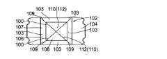
図17(a)に示す形態では、載置部102に突出脚部103を形成する脚部形成部100は、図17(b)にも断面図として示すように、非接着領域106において容器の内側から外側に向けて凸加工が施された部分(凸加工部)105を備えており、非接着領域106に充填材が封入されている状態で、凸加工部105は、非封入部108を囲んで矩形環状に延設している底部充填材封入部107の他の部分よりも載置面側に突出していて、底部充填材封入部107の角部に配置された4箇所の突出脚部103を形成している。凸加工部105は、例えばヒートエンボス加工や、圧空成形、真空成形等によるシート成形によって、底面シート104に容易に設けることができる。 In the form shown in FIG. 17A, the
凸加工部105による突出脚部103は、非封入部108を囲んで環状に延設する底部充填材封入部107による載置部102に、図17(d)に示すように、4箇所以上(図17(d)では6箇所)設けることができ、図17(e)に示すように、3箇所にのみ設けることもできる。環状に延設する底部充填材封入部107による載置部102は、1箇所の非封入部108を囲んで環状に延設するものである必要は必ずしも無く、図17(f)に示すように、2箇所以上の非封入部108を囲んで環状に延設するものであっても良い。 As shown in FIG. 17D, the
図18(a)に示す形態では、載置部102に突出脚部103を形成する脚部形成部100は、図18(b)にも断面図として示すように、非接着領域106において容器の外側から内側に向けて凹加工が施された部分(凹加工部)109を備えており、非接着領域106に充填材が封入されている状態で、凹加工部109は、外側への膨出が抑制されており、底部充填材封入部107における他の部分は、載置面側に突出していて、4箇所の突出脚部103を形成している。突出脚部103は、非封入部108を囲んで矩形環状に延設している底部充填材封入部107の、4箇所の角部に配置されている。凹加工部109は、例えばヒートエンボス加工や、圧空成形、真空成形等によるシート成形によって、底面シート104に容易に設けることができる。 In the form shown in FIG. 18A, the
凹加工部109による脚部形成部100によって形成された突出脚部103は、図18(c)に示すように、非封入部108を囲んで矩形環状に延設する底部充填材封入部107による載置部102の、各辺部の中央部分に配置して4箇所に設けることもでき、図18(d)に示すように、3箇所に設けることもできる。図18(e)に示すように、非接着領域106及び底部充填材封入部107が、非封入部108と比較して広い領域に設けられている場合に、広い領域の底部充填材封入部107に対してバランスの良い大きさで配置して、突出脚部103を、3箇所に設けることもできる。 As shown in FIG. 18C, the
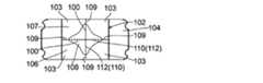
図19(a)に示す形態では、載置部102に突出脚部103を形成する脚部形成部100は、図19(b)にも断面図として示すように、底部充填材封入部107に複数のシワ109が形成されるように誘導するシワ誘導部110を備えており、非接着領域106に充填材が封入されている状態で、形成された隣接する各一対のシワ109の間の部分は、シワ109の部分よりも下方に突出していて、突出脚部103を形成している。図19(a)に示す形態では、シワ誘導部110は、非接着領域106に設けられた、4本の線状凹溝加工部111となっている。4本の線状凹溝加工部111は、非封入部108を囲んで矩形環状に延設している底部充填材封入部107による載置部102の各辺部の中央部分に、4箇所のシワ109を形成できるように設けられている。線状凹溝加工部111は、例えばヒートエンボス加工や、圧空成形、真空成形等によるシート成形によって、底面シート104に容易に設けることができる。線状凹溝加工部111によるシワ誘導部110は、非接着領域106に充填材が封入されている状態において、当該線状凹溝加工部110に応力が集中することで上方に折れ曲がってシワ109を形成し(図19(b)参照)、各一対のシワ109の間の部分を突出脚部103として、シワ109の部分よりも下方に突出させるようになっている。 In the form shown in FIG. 19 (a), the leg
線状凹溝加工部111によるシワ誘導部110は、図19(c)に示すように、非封入部108を囲んで矩形環状に延設している底部充填材封入部107の4箇所の角部にシワ109が形成されるように、非接着領域106の4箇所の角部に形成することもでき、図19(d)に示すように、4箇所の角部及び4辺の中央部分の合計8箇所に形成することもできる。シワ109が形成される環状に延設する底部充填材封入部107による載置部102は、矩形状の非封入部108を囲んで延設するものである必要は必ずしも無く、図19(e)に示すように、円形状の非封入部108を囲んで延設するものであっても良い。 As shown in FIG. 19C, the
図20(a)に示す形態では、載置部102に突出脚部103を形成する脚部形成部100は、図20(b)にも断面図として示すように、図19(a)に示す形態と同様に、底部充填材封入部107に複数のシワ109が形成されるように誘導するシワ誘導部110を備えており、非接着領域106に充填材が封入されている状態で、形成された隣接する各一対のシワ109の間の部分は、シワ109の部分よりも下方に突出していて、突出脚部103を形成している。図20(a)に示す形態では、シワ誘導部110は、非封入部108から非接着領域106に至るまで直線状に延設して設けられた、直交して配置された2本の罫線加工部112となっている。直交する2本の罫線加工部112は、非封入部108を囲んで矩形環状に延設している底部充填材封入部107による載置部102の各辺部の中央部分に、4箇所のシワ109を形成できるように設けられている。罫線加工部112は、例えばナイフのエッジを押し付けること等による罫線加工や、折り目を付けること等による折り加工によって、底面シート104に容易に設けることができる。罫線加工部112によるシワ誘導部110は、非接着領域106に充填材が封入されている状態において、当該罫線加工部112に応力が集中することで上方に折れ曲がってシワ109を形成し(図20(b)参照)、各一対のシワ109の間の部分を突出脚部103として、シワ109の部分よりも下方に突出させるようになっている。 In the form shown in FIG. 20 (a), the leg
罫線加工部112によるシワ誘導部110は、図20(c)に示すように、非封入部108を囲んで矩形環状に延設している底部充填材封入部107の4箇所の角部にシワ109が形成されるように、非接着領域106の角部に向けて2本延設させることもでき、図20(d)に示すように、角部及び各辺の中央部分に向けて延設させて、4本設けることもできる。シワ109が形成された環状に延設する底部充填材封入部107による載置部102は、矩形状の非封入部108を囲んで延設するものである必要は必ずしも無く、図20(e)に示すように、その他の形状の非封入部108を囲んで延設するものであっても良い。 As shown in FIG. 20 (c), the
なお、罫線加工部112によるシワ誘導部110や、線状凹溝加工部111によるシワ誘導部110は、図21(a)に示すように、非接着領域106による底部充填材封入部107と非封入部108の双方に連続して設けることもでき、図21(b)に示すように、非接着領域106による底部充填材封入部107のみに設けることもでき、図21(c)に示すように、非封入部108のみに設けることもできる。図21(d)に示すように、非封入部108のみに設けたものと、非接着領域106による底部充填材封入部107と非封入部108の双方に連続して設けたものとを混在させることもできる。 As shown in FIG. 21A, the
また、脚部形成部100は、図17(a)に示す凸加工部105を備えるものと、図18(a)に示す凹加工部109を備えるものと、図19(a)に示す線状凹溝加工部111によるシワ誘導部110を備えるものと、図20(a)に示す罫線加工部112によるシワ誘導部110を備えるものとを、適宜組み合わせて形成することもできる。図22(a)、(b)には、凸加工部105を突出脚部103とする例として、凸加工部105と、凹加工部109と、線状凹溝加工部111によるシワ誘導部110と、罫線加工部112によるシワ誘導部110とを組み合わせた脚部形成部100が記載されている。図22(c)には、同じく凸加工部105を突出脚部103とする例として、凸加工部105と、罫線加工部112によるシワ誘導部110とを組み合わせた脚部形成部100が記載されている。 Further, the
本実施形態では、上述のような脚部形成部100を構成する、凸加工部105や、凹加工部109や、線状凹溝加工部111によるシワ誘導部110や、罫線加工部112によるシワ誘導部110を設ける方法として、例えば複数のフィルム層を有するシート材で構成されている底面シート104の、非接着領域106を挟んで配置される外側のフィルム層と内側のフィルム層とを、互いに溶着して非接着領域106を形成してから、外側のフィルム層及び内側のフィルム層に対して、ヒートエンボス加工、罫線加工、折り加工等を行う方法を用いることができる。また、外側のフィルム層及び内側のフィルム層の各々に、ヒートエンボス加工、罫線加工、折り加工等を行ってから、これらのフィルム層を溶着することによって、非接着領域106を形成する方法を用いることもできる。さらに、外側のフィルム層のみに、ヒートエンボス加工、罫線加工、折り加工等を行ってから、外側のフィルム層と内側のフィルム層とを溶着することによって、非接着領域106を形成する方法を用いることもできる。 In the present embodiment, the
また、本実施形態では、図23(a)に示すように、前後一対の正面部シート120a,120aの下端部分の両側の側縁部と、これらの正面部シート120a,120aの下端部分の内側に二つ折りにして折込まれた底面シート121の両側の側縁部とを、ヒートシール等により接合して形成された下部接合部122の下端部が、底部充填材封入部123によって底面シート121に設けられた載置部124よりも下方に突出しないようにして、シート材容器125を載置面に載置した際の自立安定性を、さらに向上させることができるようになっている。 Further, in the present embodiment, as shown in FIG. 23A, the side edges on both sides of the lower end portions of the pair of front and rear
すなわち、図23(a)に示す形態では、図23(b)の、シート材容器125に使用される容器用シート材料126の展開正面図に示すように、正面部シート120a,120aと底面シート121との境目部分に、これらのシートの両側の縁部から当該境目部分に沿って内側に食い込むように延設させて、相当の幅を有する境目切欠き127が形成されている。これによって、シート材容器125が形成された際に、図23(c)に示すように、正面部シート120a,120aの下端部分の両側の側縁部と、底面シート121の両側の側縁部とが接合されて形成された下部接合部122の下端部には、下端切欠き128が形成されるので、この下端切欠き128によって、図23(a)に示すように、下部接合部122の下端部を、載置部124よりも一段高く配置することが可能になる。 That is, in the form shown in FIG. 23 (a), as shown in the developed front view of the
またこれによって、図24(a)、(b)に示すように、正面部シート120a,120aの下端部分の両側の側縁部と、底面シート121の両側の側縁部とが接合されて形成された下部接合部122の下端部に下端切欠きが設けられていない場合のように、下部接合部122の下端部が載置面に当たりやすくなって、シート材容器125'が不安定になるのを、効果的に回避することが可能になる。 Further, as shown in FIGS. 24A and 24B, the side edge portions on both sides of the lower end portions of the
なお、本発明は上記実施形態に限定されることなく種々の変更が可能である。例えば、シート材を構成するフィルム層の層間は、ラミネート接着剤を用いたラミネーション方法によって接着されている必要は必ずしも無く、公知のその他の方法によって接着されていても良い。例えば、UV硬化接着剤や瞬間接着剤等の、その他の接着剤を用いた接着方法も採用することができる。非接着領域が設けられた層間もまた、ラミネート接着剤を用いたラミネーション方法によって接着されている必要は必ずしも無く、公知のその他の方法によって、非接着領域を備えるように接着されていても良い。非接着領域は、上述のように、フィルム層の表面に、例えば糊殺し剤を塗布して非接着処理を施すことによって設けることもできる。シート材は、最内層と中間層と最外層とからなる3層のフィルム層を備えている必要は必ずしも無く、2層又は4層以上のフィルム層を備えていても良い。例えばシート材が3層のフィルム層からなる場合に、非接着領域は、最内層のシーラントフィルム層と中間層との間に形成されている必要は必ずしも無く、中間層と最外層との間に形成されていても良い。 The present invention is not limited to the above embodiment, and various modifications can be made. For example, the layers of the film layer constituting the sheet material do not necessarily have to be adhered by a lamination method using a laminate adhesive, and may be adhered by another known method. For example, an adhesive method using other adhesives such as a UV curable adhesive and an instant adhesive can also be adopted. The layers provided with the non-adhesive regions also do not necessarily have to be adhered by a lamination method using a laminate adhesive, and may be adhered so as to include the non-adhesive regions by other known methods. As described above, the non-adhesive region can also be provided by applying, for example, a glue-killing agent to the surface of the film layer and performing a non-adhesive treatment. The sheet material does not necessarily have to include a three-layer film layer composed of an innermost layer, an intermediate layer, and an outermost layer, and may include two or four or more film layers. For example, when the sheet material is composed of three film layers, the non-adhesive region does not necessarily have to be formed between the innermost sealant film layer and the intermediate layer, and is between the intermediate layer and the outermost layer. It may be formed.
また、中間層は、バリアフィルム層とシーラントフィルム層で用いられる、例えばポリエチレン樹脂で形成された層を有して構成することもできる。シーラントフィルム層で用いられる樹脂で形成された層と、最内層であるシーラントフィルム層とを、パターン化された熱板またはヒートシールバー等を用いてヒートシールすることで、非接着領域を、中間層と最内層の間に所望の形状で形成することもできる。この場合、収容部に収容される内容物によっては、中間層を、シーラントフィルム層で用いられる樹脂で形成された単層とすることもできる。また、直線状のヒートシールバーを用いて、シート材の、互いに離間した複数個所をヒートシールすることにより、非接着領域を中間層と最内層間に形成することもできる。なお、前記シーラントフィルム層で用いられる樹脂で形成された層は、隣接するシーラントフィルム層を構成する樹脂と異なった樹脂で形成されても良い。なお、シーラントフィルム層で用いられる樹脂で形成される層は、例えば、低密度ポリエチレン樹脂(LDPE)、中密度ポリエチレン樹脂(MDPE)、高密度ポリエチレン樹脂(HDPE)、直鎖状低密度ポリエチレン樹脂(L−LDPE)、ポリプロピレン樹脂(PP)等を使用して形成することができる。また、本明細書において、前述のように接着には粘着も含まれとともに、ヒートシールも含まれるものとする。また、収容部に収容される内容物は、液体洗剤等の内容液の他、粉粒体等のその他の内容物であってもよく、食料品や医薬品等であっても良い。 Further, the intermediate layer may be configured to have a layer made of, for example, a polyethylene resin, which is used as a barrier film layer and a sealant film layer. The non-adhesive region is intermediated by heat-sealing the layer formed of the resin used in the sealant film layer and the innermost sealant film layer using a patterned hot plate or a heat seal bar or the like. It can also be formed in a desired shape between the layers and the innermost layer. In this case, depending on the contents accommodated in the accommodating portion, the intermediate layer may be a single layer made of the resin used in the sealant film layer. Further, a non-adhesive region can be formed between the intermediate layer and the innermost layer by heat-sealing a plurality of portions of the sheet material separated from each other by using a linear heat seal bar. The layer formed of the resin used in the sealant film layer may be formed of a resin different from the resin constituting the adjacent sealant film layer. The layer formed of the resin used in the sealant film layer is, for example, a low-density polyethylene resin (LDPE), a medium-density polyethylene resin (MDPE), a high-density polyethylene resin (HDPE), or a linear low-density polyethylene resin (a linear low-density polyethylene resin). It can be formed using L-LDPE), polypropylene resin (PP), or the like. Further, in the present specification, as described above, the adhesion includes not only adhesiveness but also heat sealing. Further, the content contained in the storage unit may be a content liquid such as a liquid detergent, or other content such as powder or granular material, or may be a food product, a pharmaceutical product, or the like.
また、非接着領域に充填材を封入して形成される充填材封入部は、上記実施形態の形状に限定されることなく、容器の種類や用途に応じて、種々のパターンの形状となるように形成することができる。充填材封入部は、収容部の胴部シート及び底面シートの両方に形成されている必要は必ずしも無く、底面シートのみに、底部充填材封入部が設けられていれば良い。また、胴部シート及び底面シートのそれぞれに、外部連通口が設けられていても良い。充填材封入部は、その全体が線状に延設して設けられている必要は必ずしも無く、例えば図13に示すように、線状の充填材封入部16"の任意の箇所として、例えば胴部12"の胴部シート12a"の底部角部分に、横幅が広がった円形(略円形を含む)の面状の充填材封入部24を介在させて設けることもできる。落下による破袋の懸念がある胴部シート12a"の底部角部分に、面状の充填材封入部24を設けておくことにより、充填材封入部24による緩衝効果によって、シート材容器の落下強度を向上させることができる。なお、非接着領域に充填材を封入して形成される充填材封入部は、内容物の収容と同時に形成されても良く、予め形成されてから内容物を収容しても良く、内容物を収容した後に形成されても良い。 Further, the filler encapsulating portion formed by enclosing the filler in the non-adhesive region is not limited to the shape of the above embodiment, and may have various patterns depending on the type and application of the container. Can be formed into. The filler encapsulation portion does not necessarily have to be formed on both the body sheet and the bottom sheet of the accommodating portion, and it is sufficient that the bottom filler encapsulation portion is provided only on the bottom sheet. Further, each of the body sheet and the bottom sheet may be provided with an external communication port. The filler encapsulation portion does not necessarily have to be provided so as to extend linearly as a whole, and as shown in FIG. 13, for example, as an arbitrary portion of the linear
さらに、例えば図14に示すように、シート材容器30は、トリガー式の吐出装置31が取り付けられたボトル形状の容器として用いることもできる。シート材容器30をボトル形状の容器として用いる場合には、補強用の充填材封入部32によって、ボトル形状が強固に保持されるように効果的に補強することが可能になる。また例えば図15に示すように、補強用の充填材封入部34と連通する外部連通口35は、横方向に向けて開口するように設けることもできる。 Further, for example, as shown in FIG. 14, the
さらにまた、本発明のシート材容器は、側面に襠部を有するガゼットタイプのシート材容器であっても良い。すなわち、シート材容器を構成する胴部シートは、正面側のシート、背面側のシート及びこれらの間に一対の側面側のシートを備えていても良い。 Furthermore, the sheet material container of the present invention may be a gusset type sheet material container having a gusset on the side surface. That is, the body sheet constituting the sheet material container may include a front side sheet, a back side sheet, and a pair of side side sheets between them.
上述した各実施形態に関し、本発明は更に以下のシート材容器、シート材容器の製造方法、容器製品、容器製品の製造方法、容器用シート材料、容器用シート材料の製造方法を開示する。
<1>複数のフィルム層を積層したシート材で構成されている、胴部と、載置面に対向して配置される底部とを備えるシート材容器であって、
前記胴部を構成している胴部シートは周縁部分にシート材同士が接合されている接合部を備え、前記底部を構成している底面シートは、前記複数のフィルム層の層間に非接着領域が設けられており、該非接着領域に充填材が封入されることで、底部充填材封入部が形成されているシート材容器。With respect to each of the above-described embodiments, the present invention further discloses the following sheet material container, a method for producing a sheet material container, a container product, a method for producing a container product, a container sheet material, and a method for producing a container sheet material.
<1> A sheet material container composed of a sheet material in which a plurality of film layers are laminated, and having a body portion and a bottom portion arranged so as to face the mounting surface.
The body sheet constituting the body portion includes a joint portion in which the sheet materials are bonded to each other at the peripheral edge portion, and the bottom surface sheet constituting the bottom portion has a non-adhesive region between the layers of the plurality of film layers. Is provided, and a filling material is sealed in the non-adhesive region to form a bottom filling material sealing portion.
<2>好ましくは前記底部を構成している底面シートが、載置面に載置されて容器を自立させる載置部(底部)を形成している前記<1>記載のシート材容器。<2> The sheet material container according to <1>, wherein the bottom sheet constituting the bottom portion is preferably placed on the mounting surface to form a mounting portion (bottom portion) that allows the container to stand on its own.
<3>好ましくは前記底部充填材封入部は、前記底面シートに設けられている折り畳み用の折り目と交差して配置される部分を含む前記<1>又は<2>記載のシート材容器。<3> The sheet material container according to <1> or <2>, wherein the bottom filler encapsulating portion preferably includes a portion arranged so as to intersect the folding fold provided on the bottom sheet.
<4>好ましくは前記底部充填材封入部は、前記胴部において対向する正面側から背面側に連続する部分を備えている前記<1>〜<3>のいずれか1記載のシート材容器。<4> The sheet material container according to any one of <1> to <3>, wherein the bottom filler encapsulating portion preferably includes a portion of the body portion that is continuous from the front side to the back side.
<5>好ましくは前記底面シートは、前記底部充填材封入部を形成している非接着領域に囲まれた、前記充填材が封入されていない非封入部を備えている前記<1>〜<4>のいずれか1記載のシート材容器。<5> Preferably, the bottom sheet includes a non-encapsulated portion in which the filler is not sealed, surrounded by a non-adhesive region forming the bottom filler-encapsulated portion. The sheet material container according to any one of 4>.
<6>好ましくは前記底部充填材封入部は、前記底面シートにおいて前記載置部(底部)の周縁に沿って連続して形成されている前記<2>〜<5>のいずれか1記載のシート材容器。<6> The one according to any one of <2> to <5>, wherein the bottom filler encapsulating portion is continuously formed along the peripheral edge of the previously described placing portion (bottom portion) in the bottom sheet. Sheet material container.
<7>好ましくは前記胴部シートは、前後に対向する一対の正面シートを備えており、該正面シートは、前記複数のフィルム層の層間に設けられた非接着領域に充填材が封入されることで、正面部充填材封入部が形成されており、該正面部充填材封入部を構成する非接着領域は、前記底面シートにおける前記底部充填材封入部を形成している非接着領域と連通している前記<1>〜<6>のいずれか1記載のシート材容器。<7> Preferably, the body sheet includes a pair of front and rear facing sheets, and the front sheet is filled with a filler in a non-adhesive region provided between layers of the plurality of film layers. As a result, the front surface filler encapsulation portion is formed, and the non-adhesive region constituting the front surface filler encapsulation portion communicates with the non-adhesive region forming the bottom filler encapsulation portion in the bottom sheet. The sheet material container according to any one of <1> to <6>.
<8>好ましくは前記正面部充填材封入部は、線状に延設する部分を含んで形成されている前記<7>記載のシート材容器。<8> The sheet material container according to <7>, wherein the front filling material sealing portion is preferably formed including a linearly extending portion.
<9>好ましくは前記非接着領域が設けられている前記複数のフィルム層の層間は、接着剤を用いて接着されており、前記非接着領域を含む塗布パターンにより前記接着剤を塗布することによって、前記非接着領域が形成されている前記<1>〜<8>のいずれか1記載のシート材容器。<9> Preferably, the layers of the plurality of film layers provided with the non-adhesive region are adhered using an adhesive, and the adhesive is applied by a coating pattern including the non-adhesive region. The sheet material container according to any one of <1> to <8>, wherein the non-adhesive region is formed.
<10>好ましくは前記非接着領域が設けられている前記複数のフィルム層の層間は、接着剤を用いて接着されており、前非接着領域に対応する部分の少なくとも一方のフィルム層の表面に、非接着処理が施されていることによって、前記非接着領域が形成されている前記<1>〜<8>のいずれか1記載のシート材容器。<10> Preferably, the layers of the plurality of film layers provided with the non-adhesive region are adhered to each other by using an adhesive, and are attached to the surface of at least one film layer of the portion corresponding to the pre-adhesive region. The sheet material container according to any one of <1> to <8>, wherein the non-adhesive region is formed by being subjected to the non-adhesive treatment.
<11>好ましくは前記底面シートの周縁部分にはシート材同士が接合されている接合部を備え、前記底面シート又は前記底面シートの周縁部分の前記接合部に開口して、前記非接着領域に連通する外部連通口が設けられており、前記外部連通口は、前記非接着領域に充填材を供給した後に封止されている前記<1>〜<10>のいずれか1記載のシート材容器。<11> Preferably, the peripheral portion of the bottom sheet is provided with a joint portion in which the sheet materials are joined to each other, and the bottom sheet or the peripheral portion of the bottom sheet is opened to the joint portion in the non-adhesive region. The sheet material container according to any one of <1> to <10>, wherein an external communication port for communication is provided, and the external communication port is sealed after supplying a filler to the non-adhesive region. ..
<12>前記<1>〜<10>のいずれか1記載のシート材容器の製造方法であって、前記非接着領域が前記底面シート部に設けられた前記シート材の原反を形成する工程、前記原反の個々のシート材容器と対応する部分のシート材同士の周縁部分を接合する工程、接合された前記原反を所定寸法に切断する工程、及び前記非接着領域に充填材を封入して、前記底部充填材封入部を形成する工程を含むシート材容器の製造方法。<12> The step of forming the raw fabric of the sheet material in which the non-adhesive region is provided on the bottom sheet portion in the method for manufacturing a sheet material container according to any one of <1> to <10>. , The step of joining the peripheral portions of the sheet materials corresponding to the individual sheet material containers of the raw fabric, the step of cutting the joined raw fabric to a predetermined size, and filling the non-adhesive region with the filler. A method for manufacturing a sheet material container, which comprises a step of forming the bottom filler sealing portion.
<13>前記<1>〜<11>のいずれか1記載のシート材容器を用いた容器製品であって、前記胴部と前記底部に囲まれる収容部に、内容物が収容されている容器製品。<13> A container product using the sheet material container according to any one of <1> to <11>, wherein the contents are stored in a storage portion surrounded by the body portion and the bottom portion. Product.
<14>前記<1>〜<11>のいずれか1記載のシート材容器に使用され、複数のフィルム層を積層したシート材を用いて形成される容器用シート材料であって、
胴部シートと、該胴部シートの周縁部分に形成されているシート材同士の接合部と、底面シートとを含んでおり、
該底面シートは、折り畳み用の折り目を備えており、該折り畳み用の折り目を介して平坦に重ねて折り畳まれた状態となっており、
前記底面シートは、前記複数のフィルム層の層間に、充填材が封入される非接着領域が設けられている容器用シート材料。<14> A container sheet material used for the sheet material container according to any one of <1> to <11>, which is formed by using a sheet material in which a plurality of film layers are laminated.
It includes a body sheet, a joint portion between sheet materials formed on a peripheral portion of the body sheet, and a bottom sheet.
The bottom sheet is provided with folds for folding, and is in a state of being flatly stacked and folded through the folds for folding.
The bottom sheet is a container sheet material in which a non-adhesive region in which a filler is sealed is provided between layers of the plurality of film layers.
<15>前記<13>記載の容器製品の製造方法であって、前記シート材容器の前記胴部と前記底部に囲まれる収容部に内容物を収容する工程を含む容器製品の製造方法。<15> The method for producing a container product according to <13>, which comprises a step of accommodating the contents in an accommodating portion surrounded by the body portion and the bottom portion of the sheet material container.
<16>前記<14>に記載の容器用シート材料の製造方法であって、前記非接着領域が前記底面シートに設けられた前記シート材の原反を形成する工程、前記原反の個々の容器用シート材料と対応する部分の周縁部分を接合する工程、及び接合された前記原反を所定寸法に切断する工程を含む容器用シート材料の製造方法。<16> The method for producing a sheet material for a container according to <14>, wherein the non-adhesive region forms a raw fabric of the sheet material provided on the bottom sheet, and individual of the raw fabric. A method for producing a container sheet material, which comprises a step of joining a peripheral portion of a portion corresponding to the container sheet material and a step of cutting the joined raw fabric to a predetermined size.
<17>好ましくは、前記充填材が流体、粉粒体、樹脂、発泡材の何れか又はこれらから適宜選択された混合物である前記<1>〜<11>のいずれか1記載のシート材容器。<17> The sheet material container according to any one of <1> to <11>, wherein the filler is any one of a fluid, a powder or granular material, a resin, and a foaming material, or a mixture appropriately selected from these. ..
<18>好ましくは前記非接着領域が設けられたフィルム層は、シーラントフィルム層で用いられる樹脂で形成された層を有し、該フィルム層と、該フィルム層に隣接するシーラントフィルム層とがヒートシールにより接着されている前記<1>〜<11>のいずれか1記載のシート材容器。<18> Preferably, the film layer provided with the non-adhesive region has a layer formed of the resin used in the sealant film layer, and the film layer and the sealant film layer adjacent to the film layer are heated. The sheet material container according to any one of <1> to <11>, which is adhered by a seal.
<19>好ましくは前記胴部シートは、前後一対の正面シートを備えており、これらの正面シートは、前記シート材を構成する前記複数のフィルム層の層間に設けられた非接着領域に充填材が封入されて、正面部充填材封入部が形成されており、前記正面部充填材封入部は、横方向封入部、縦方向封入部及び底辺部湾曲封入部を含んで形成されている前記<1>〜<11>のいずれか1記載のシート材容器。<19> Preferably, the body sheet includes a pair of front and rear front sheets, and these front sheets are filled in a non-adhesive region provided between layers of the plurality of film layers constituting the sheet material. Is sealed to form a front filler encapsulation portion, and the front filler encapsulation portion is formed including a lateral encapsulation portion, a vertical encapsulation portion, and a bottom curved encapsulation portion. The sheet material container according to any one of 1> to <11>.
<20>前記縦方向封入部は3本以上設けられており、両端部の一対の縦方向封入部によって挟まれた縦方向封入部は、その下端部が、前記底辺部湾曲封入部に連続することなく、底辺部湾曲封入部と離間して設けられている前記<19>記載のシート材容器。<20> Three or more of the vertical encapsulation portions are provided, and the lower end portion of the vertical encapsulation portion sandwiched between the pair of vertical encapsulation portions at both ends is continuous with the bottom curved encapsulation portion. The sheet material container according to <19>, which is provided separately from the bottom curved sealing portion.
<21>好ましくは前記前後一対の正面シート部のうちの、一方の正面部シートの上辺部分の接合部に開口して、前記非接着領域に充填材を供給するための外部連通口が、前記非接着領域と連通して設けられており、前記外部連通口は、前記非接着領域に充填材を供給した後に封止されている前記<7>〜<11>、<19>及び<20>のいずれか1記載のシート材容器。<21> The external communication port for supplying the filler to the non-adhesive region is preferably opened at the joint portion of the upper side portion of one of the front and rear front sheet portions. The external communication port is provided so as to communicate with the non-adhesive region, and the external communication port is sealed after supplying the filler to the non-adhesive region. The sheet material container according to any one of.
<22>好ましくは前記外部連通口は、対向する一方の内壁面がシーラントフィルム層による壁面となっており、他方の内壁面がバリアフィルム層による壁面となっており、該バリアフィルム層による他方の内壁面を覆って、一方の内壁面側の面がシーラントフィルム層となっているシール接合片が接着されている前記<11>又は<21>記載のシート材容器。<22> Preferably, in the external communication port, one of the inner wall surfaces facing each other is a wall surface made of a sealant film layer, the other inner wall surface is a wall surface made of a barrier film layer, and the other inner wall surface is made of the barrier film layer. The sheet material container according to <11> or <21> above, wherein a seal joint piece covering the inner wall surface and one surface on the inner wall surface side is a sealant film layer is adhered.
<23>好ましくは前記線状の充填材封入部に、線状の充填材封入部の横幅よりも広い面状、円形状、球形状の充填材封入部を単独でまたは適宜組み合わせて、介在させて設けられている前記<8>記載のシート材容器。<23> Preferably, a planar, circular, or spherical filler encapsulation portion wider than the width of the linear filler encapsulation portion is interposed in the linear filler encapsulation portion alone or in combination as appropriate. The sheet material container according to <8>.
<24>好ましくは前記底部充填材封入部が形成されることで、前記底面シートが展開して、前記載置部(底部)が形成される前記<2>記載のシート材容器。<24> The sheet material container according to <2>, wherein the bottom sheet is expanded by forming the bottom filler sealing portion, and the previously described placing portion (bottom portion) is formed.
<25>好ましくは前記底部充填材封入部は、前記底面シート部に設けられた折り畳み用の折り目と略垂直に交差して設けられた交差封入部を含んで構成されている前記<24>記載のシート材容器。<25> The above-described <24>, wherein the bottom filler encapsulation portion preferably includes a cross encapsulation portion provided so as to intersect substantially perpendicularly with a folding fold provided in the bottom sheet portion. Sheet material container.
<26>好ましくは前記底部充填材封入部は、一対の前記交差封入部76gと、一対の連通リブ部とを含む、矩形枠形状を有するように形成されている前記<25>記載のシート材容器。<26> The sheet material according to <25>, wherein the bottom filler encapsulating portion is formed so as to have a rectangular frame shape including a pair of the
<27>好ましくは前記底部充填材封入部は、前後一対の正面部シートの底辺部分と、底面マチ部シートの周縁部分とを接合した両側の一対の接合部に、跨るように連続して配置されて設けられた、中央部分に非封入部を有する矩形状の面状封入部を含んで形成されている前記<24>記載のシート材容器。<27> Preferably, the bottom filler encapsulating portion is continuously arranged so as to straddle the pair of joint portions on both sides where the bottom portion of the pair of front and rear front sheet and the peripheral portion of the bottom gusset sheet are joined. The sheet material container according to <24>, which is provided so as to include a rectangular planar encapsulation portion having a non-encapsulation portion in the central portion.
<28>好ましくは前記非封入部は、円形の非封入部となっている前記<27>記載のシート材容器。<28> The sheet material container according to <27>, wherein the non-encapsulated portion is preferably a circular non-encapsulated portion.
<29>好ましくは前記非封入部は、これの角部分を、矩形状の前記面状封入部の4方の辺部における、矩形状の4方の角部分から離間した中間部分に向けた状態で配置して、設けられている前記<27>記載のシート材容器。<29> Preferably, the non-encapsulated portion is in a state in which the corner portions thereof are directed to the intermediate portions of the four side portions of the rectangular sealed portion, which are separated from the four square portions of the rectangular shape. The sheet material container according to <27>, which is arranged and provided in.
<30>好ましくは前記非封入部は、菱形形状の非封入部となっている前記<29>記載のシート材容器。<30> The sheet material container according to <29>, wherein the non-encapsulated portion is preferably a diamond-shaped non-encapsulated portion.
<31>好ましくは前記非封入部は、三角形状の非封入部となっている前記<29>記載のシート材容器。<31> The sheet material container according to <29>, wherein the non-encapsulated portion is preferably a triangular non-encapsulated portion.
<32>複数のフィルム層を積層したシート材で構成されている、胴部と、載置面に対向して配置される底部を備えるシート材容器であって、
前記胴部を構成している胴部シートは周縁部分にシート材同士が接合されている接合部を備え、前記底部を構成している底面シートと、前記胴部シートとの境界に、前記複数のフィルム層の層間に非接着領域が設けられており、該非接着領域に充填材が封入されることで、底部充填材封入部が形成されているシート材容器。<32> A sheet material container having a body portion and a bottom portion arranged to face the mounting surface, which is composed of a sheet material in which a plurality of film layers are laminated.
The body sheet constituting the body portion includes a joint portion in which the sheet materials are bonded to each other at the peripheral edge portion, and the plurality of the body sheet is formed at the boundary between the bottom sheet forming the bottom portion and the body sheet. A sheet material container in which a non-adhesive region is provided between layers of the film layer, and a filler is sealed in the non-adhesive region to form a bottom filler encapsulation portion.
<33>複数のフィルム層を積層したシート材で構成されている、胴部と、載置面に対向して配置される底部を備えるシート材容器であって、
前記胴部を構成している胴部シートは周縁部分にシート材同士が接合されている接合部を備え、前記胴部シートは、一対の正面と、正面と正面との間の一対の側面とを備え、前記接合部は、前記一対の側面の範囲に位置しており、前記正面と側面との境界に、前記複数のフィルム層の層間に非接着領域が設けられており、該接着領域に充填材が封入されることで、正面部充填材封入部が形成されているシート材容器。<33> A sheet material container composed of a sheet material in which a plurality of film layers are laminated, and having a body portion and a bottom portion arranged so as to face the mounting surface.
The body sheet constituting the body portion includes a joint portion in which the sheet materials are joined to each other on the peripheral edge portion, and the body body sheet has a pair of front surfaces and a pair of side surfaces between the front surfaces and the front surfaces. The joint is located in the range of the pair of side surfaces, and a non-adhesive region is provided between the layers of the plurality of film layers at the boundary between the front surface and the side surface. A sheet material container in which a filling material encapsulation portion is formed in the front portion by encapsulating the filler material.
<34>複数のフィルム層を有するシート材で構成されている、胴部と、載置面に対向して配置される底部とを備えるシート材容器であって、
前記胴部を構成している胴部シートは、周縁部分にシート材同士が接合されている接合部を備えており、
前記底部を構成している底面シートには、前記複数のフィルム層の層間に非接着領域が設けられており、該非接着領域は、充填材が封入されていて、底部充填材封入部を形成しており、
該底部充填材封入部は、底面シートの非封入部を囲んで環状に延設していると共に、載置面に載置されて容器を自立させる少なくとも3箇所の突出脚部を形成しており、前記突出脚部は、前記底部に設けられた脚部形成部によって、前記底部充填材封入部の他の部分よりも載置面側に突出しているシート材容器。<34> A sheet material container including a body portion made of a sheet material having a plurality of film layers and a bottom portion arranged so as to face the mounting surface.
The body sheet constituting the body portion is provided with a joint portion in which the sheet materials are joined to each other at the peripheral edge portion.
The bottom sheet constituting the bottom portion is provided with a non-adhesive region between the layers of the plurality of film layers, and the non-adhesive region is filled with a filler to form a bottom filler encapsulation portion. And
The bottom filler-encapsulated portion surrounds the non-encapsulated portion of the bottom sheet and extends in an annular shape, and forms at least three protruding legs that are placed on the mounting surface to allow the container to stand on its own. The protruding leg portion is a sheet material container that protrudes toward the mounting surface side from the other portion of the bottom filler encapsulation portion by the leg portion forming portion provided on the bottom portion.
<35>好ましくは前記脚部形成部は、前記非接着領域における他の部分よりも延設方向と垂直な方向の幅が大きくなっている部分を備えており、前記非接着領域に充填材が封入されている状態で、前記幅が大きくなっている部分は、他の部分よりも断面積が大きくなるように膨出していることにより、前記底部充填材封入部の他の部分よりも載置面側に突出していて、前記突出脚部を形成している前記<34>記載のシート材容器。<35> Preferably, the leg forming portion includes a portion in the non-adhesive region in a direction perpendicular to the extending direction as compared with other portions, and a filler is provided in the non-adhesive region. In the sealed state, the portion having a large width is bulged so as to have a larger cross-sectional area than the other portion, so that the portion is placed more than the other portion of the bottom filler encapsulation portion. The sheet material container according to <34>, which protrudes toward the surface side and forms the protruding leg portion.
<36>好ましくは前記脚部形成部は、前記非接着領域において容器の内側から外側に向けて凸加工が施された部分を備えており、前記非接着領域に充填材が封入されている状態で、前記凸加工が施された部分は、前記底部充填材封入部の他の部分よりも載置面側に突出していて、前記突出脚部を形成している前記<34>又は<35>記載のシート材容器。<36> Preferably, the leg forming portion includes a portion of the non-adhesive region that has been convexed from the inside to the outside of the container, and a filler is sealed in the non-adhesive region. In the above <34> or <35>, the portion subjected to the convex processing protrudes toward the mounting surface side from the other portion of the bottom filler sealing portion and forms the protruding leg portion. The sheet material container described.
<37>好ましくは前記脚部形成部は、前記非接着領域において容器の外側から内側に向けて凹加工が施された部分を備えており、前記非接着領域に充填材が封入されている状態で、前記凹加工が施された部分は、外側への膨出が抑制されており、前記底部充填材封入部における他の部分は、載置面側に突出していて、前記突出脚部を形成している前記<34>又は<35>記載のシート材容器。<37> Preferably, the leg forming portion includes a portion of the non-adhesive region that has been recessed from the outside to the inside of the container, and a filler is sealed in the non-adhesive region. The recessed portion is suppressed from bulging outward, and the other portion of the bottom filler encapsulating portion protrudes toward the mounting surface side to form the protruding leg portion. The sheet material container according to the above <34> or <35>.
<38>好ましくは前記脚部形成部は、前記底部充填材封入部に複数のシワが形成されるように誘導するシワ誘導部を備えており、前記非接着領域に充填材が封入されている状態で、形成された隣接する各一対のシワの間の部分は、シワの部分よりも下方に突出していて、前記突出脚部を形成している前記<34>〜<37>のいずれか1記載のシート材容器。<38> Preferably, the leg forming portion is provided with a wrinkle guiding portion that induces the formation of a plurality of wrinkles in the bottom filler sealing portion, and the filler is sealed in the non-adhesive region. In the state, the portion between each pair of adjacent wrinkles formed is projected downward from the wrinkled portion, and any one of the above <34> to <37> forming the protruding leg portion. The sheet material container described.
<39>好ましくは前記シワ誘導部は、前記非接着領域に設けられた、線状凹溝加工部及び/又は罫線加工部である前記<38>記載のシート材容器。<39> The sheet material container according to <38>, wherein the wrinkle induction portion is preferably a linear concave groove processed portion and / or a ruled line processed portion provided in the non-adhesive region.
<40>前記<34>〜<39>のいずれか1記載のシート材容器の製造方法であって、前記非接着領域が前記底面シート部に設けられた前記シート材の原反を形成する工程、前記原反の個々のシート材容器と対応する部分のシート材同士の周縁部分を接合する工程、接合された前記原反を所定寸法に切断する工程、及び前記非接着領域に充填材を封入して、前記底部充填材封入部を形成する工程を含むシート材容器の製造方法。<40> The step of forming the raw fabric of the sheet material in which the non-adhesive region is provided on the bottom sheet portion in the method for manufacturing a sheet material container according to any one of <34> to <39>. , The step of joining the peripheral portions of the sheet materials corresponding to the individual sheet material containers of the raw fabric, the step of cutting the joined raw fabric to a predetermined size, and filling the non-adhesive region with the filler. A method for manufacturing a sheet material container, which comprises a step of forming the bottom filler sealing portion.
<41>前記<34>〜<39>のいずれか1記載のシート材容器を用いた容器製品であって、前記胴部と前記底部に囲まれる収容部に、内容物が収容されている容器製品。<41> A container product using the sheet material container according to any one of <34> to <39>, wherein the contents are stored in a storage portion surrounded by the body portion and the bottom portion. Product.
<42>前記<41>記載の容器製品の製造方法であって、前記シート材容器の前記胴部と前記底部に囲まれる収容部に内容物を収容する工程を含む容器製品の製造方法。<42> The method for manufacturing a container product according to <41>, which comprises a step of storing the contents in a storage portion surrounded by the body portion and the bottom portion of the sheet material container.
<43>前記<34>〜<39>のいずれか1記載のシート材容器に使用され、複数のフィルム層を積層したシート材を用いて形成される容器用シート材料であって、
胴部シートと、該胴部シートの周縁部分に形成されているシート材同士の接合部と、底面シートとを含んでおり、
該底面シートは、折り畳み用の折り目を備えており、
該折り畳み用の折り目を介して平坦に重ねて折り畳まれた状態となっており、
前記底面シートは、前記複数のフィルム層の層間に、充填材が封入される非接着領域が設けられている容器用シート材料。<43> A container sheet material used for the sheet material container according to any one of <34> to <39>, which is formed by using a sheet material in which a plurality of film layers are laminated.
It includes a body sheet, a joint portion between sheet materials formed on a peripheral portion of the body sheet, and a bottom sheet.
The bottom sheet is provided with folds for folding.
It is in a state of being folded flat over the folds for folding.
The bottom sheet is a container sheet material in which a non-adhesive region in which a filler is sealed is provided between layers of the plurality of film layers.
<44>前記<43>記載の容器用シート材料の製造方法であって、前記非接着領域が前記底面シートに設けられた前記シート材の原反を形成する工程、前記原反の個々の容器用シート材料と対応する部分の周縁部分を接合する工程、及び接合された前記原反を所定寸法に切断する工程を含む容器用シート材料の製造方法。<44> The method for producing a sheet material for a container according to <43>, wherein the non-adhesive region is provided on the bottom sheet to form a raw fabric of the sheet material, and individual containers of the raw fabric. A method for producing a sheet material for a container, which comprises a step of joining a peripheral portion of a portion corresponding to the sheet material for use and a step of cutting the joined raw fabric to a predetermined size.
本発明のシート材容器、該シート材容器の製造方法、該シート材容器を用いた容器製品、該容器製品の製造方法、該シート材容器に使用される容器用シート材料、又は該容器用シート材料の製造方法によれば、補強用の充填材封入部の形状や配設位置等の選択の自由度を向上させて、容器の任意の位置に充填材封入部を設けることを可能にすることで、特に底面シート部を、充填材封入部によって効果的に補強して、容器の自立安定性を向上させたり、底面シート部の剛性を高めたりすることができる。また、本発明のシート材容器、該シート材容器の製造方法、該シート材容器に使用される容器用シート材料によれば、充填剤封入部によって、収容物の量の大小によらず、容器の立体保形性を向上させ、落下強度を高め、あるいは容器用シート材料からの立体形成性を向上することができる。また、本発明のシート材容器によれば、載置面に載置した際の自立安定性を、さらに向上させることが可能になる。 The sheet material container of the present invention, the method for manufacturing the sheet material container, the container product using the sheet material container, the method for manufacturing the container product, the sheet material for the container used for the sheet material container, or the sheet for the container. According to the material manufacturing method, it is possible to improve the degree of freedom in selecting the shape and arrangement position of the filler encapsulation portion for reinforcement so that the filler encapsulation portion can be provided at an arbitrary position in the container. Therefore, in particular, the bottom sheet portion can be effectively reinforced by the filler encapsulation portion to improve the self-sustaining stability of the container and increase the rigidity of the bottom sheet portion. Further, according to the sheet material container of the present invention, the method for manufacturing the sheet material container, and the sheet material for the container used for the sheet material container, the container regardless of the amount of the contained matter depending on the filler encapsulation portion. It is possible to improve the three-dimensional shape retention property of the container, increase the drop strength, or improve the three-dimensional formability from the container sheet material. Further, according to the sheet material container of the present invention, it is possible to further improve the self-sustaining stability when the container is placed on the mounting surface.
Claims (7)
Translated fromJapanese前記前後一対の正面部シートの周縁部分と、折り畳み用の折り目を介してこれらの正面部シートの内側に二つ折りに折込み可能な、前記底面マチ部シートの周縁部分とが、互いに接合されている接合部を備えており、
前記前後一対の正面部シートの底辺部分に沿った部分及び前記底面マチ部シートには、前記複数のフィルム層の層間に非接着領域が設けられており、該非接着領域は、充填材が封入されていて、底部充填材封入部を形成しており、
前記前後一対の正面部シートの下端部分の両側の側縁部と、これらの正面部シートの下端部分の内側に二つ折りにして折込まれた前記底面マチ部シートの両側の側縁部とを接合して形成された下部接合部の下端部が、前記底部充填材封入部によって前記底面マチ部シートによる底面シートに設けられた載置部よりも下方に突出しないようになっているシート材容器。A self-supporting portion having a body portion and a bottom portion arranged to face the mounting surface, which is composed of a sheet material including a pair of front and rear front sheet and a bottom gusset sheet having a plurality of film layers. It is a sheet material container,and the content liquid can be stored in the storage portion surrounded by the body portion and the bottom portion.
The peripheral portion of the pair of front and rear front sheet and the peripheral portion of the bottom gusset sheet that can be folded in half inside these front sheets via folding folds are joined to each other. It has a joint and
A non-adhesive region is provided between the layers of the plurality of film layers in the portion along the bottom portion of the pair of front and rear front portion sheetsand the bottom gusset portion sheet, and the non-adhesive region is filled with a filler. And forms a bottom filler encapsulation
Join the side edges on both sides of the lower end of the pair of front and rear front sheet and the side edges on both sides of the bottom gusset sheet folded in half inside the lower end of these front sheets. A sheet material container in which the lower end portion of the lower joint portion formed in the above manner does not protrude downward from the mounting portion provided on the bottom sheet by the bottom gusset portion sheet by the bottom filler sealing portion.
前後一対の正面部シートと底面マチ部シートとを有するシート材と、前記前後一対の正面部シートの周縁部分と前記底面マチ部シートの周縁部分とが互いに接合されている接合部とを含んでおり、
前記底面シートは、折り畳み用の折り目を備えており、
該折り畳み用の折り目を介して平坦に重ねて折り畳まれた状態となっており、
前記前後一対の正面部シートの底辺部分に沿った部分には、充填材が封入される非接着領域が設けられている容器用シート材料。A sheet material for a container used for the sheet material container according to claim 1 or 2, which is formed by using a sheet material in which a plurality of film layers are laminated.
Includes a sheet material having a pair of front and rear front sheet and a bottom gusset sheet, and a joint portion in which a peripheral portion of the front and rear pair of front sheet and a peripheral portion of the bottom gusset sheet are joined to each other. Ori,
The bottom sheet has creases for folding.
It is in a state of being folded flat over the folds for folding.
A sheet material for a container in which a non-adhesive region in which a filler is sealed is provided in a portion along the bottom portion of the pair of front and rear front seats.
Applications Claiming Priority (2)
| Application Number | Priority Date | Filing Date | Title |
|---|---|---|---|
| JPPCT/JP2015/075582 | 2015-09-09 | ||
| PCT/JP2015/075582WO2017042905A1 (en) | 2015-09-09 | 2015-09-09 | Sheet material container |
Related Parent Applications (1)
| Application Number | Title | Priority Date | Filing Date |
|---|---|---|---|
| JP2017102163ADivisionJP6588497B2 (en) | 2015-09-09 | 2017-05-23 | Sheet material container |
Publications (2)
| Publication Number | Publication Date |
|---|---|
| JP2019206398A JP2019206398A (en) | 2019-12-05 |
| JP6876763B2true JP6876763B2 (en) | 2021-05-26 |
Family
ID=58239251
Family Applications (3)
| Application Number | Title | Priority Date | Filing Date |
|---|---|---|---|
| JP2016574019AActiveJP6153185B1 (en) | 2015-09-09 | 2016-09-08 | Sheet material container |
| JP2017102163AActiveJP6588497B2 (en) | 2015-09-09 | 2017-05-23 | Sheet material container |
| JP2019165998AActiveJP6876763B2 (en) | 2015-09-09 | 2019-09-12 | Sheet material container |
Family Applications Before (2)
| Application Number | Title | Priority Date | Filing Date |
|---|---|---|---|
| JP2016574019AActiveJP6153185B1 (en) | 2015-09-09 | 2016-09-08 | Sheet material container |
| JP2017102163AActiveJP6588497B2 (en) | 2015-09-09 | 2017-05-23 | Sheet material container |
Country Status (6)
| Country | Link |
|---|---|
| US (3) | US11059626B2 (en) |
| EP (1) | EP3348488A4 (en) |
| JP (3) | JP6153185B1 (en) |
| CN (2) | CN108025836B (en) |
| TW (1) | TWI623467B (en) |
| WO (2) | WO2017042905A1 (en) |
Families Citing this family (23)
| Publication number | Priority date | Publication date | Assignee | Title |
|---|---|---|---|---|
| WO2017042905A1 (en)* | 2015-09-09 | 2017-03-16 | 花王株式会社 | Sheet material container |
| US11332292B2 (en) | 2017-03-07 | 2022-05-17 | Kao Corporation | Container |
| US11267617B2 (en) | 2017-03-07 | 2022-03-08 | Kao Corporation | Sheet material container |
| JP6186546B1 (en) | 2017-03-07 | 2017-08-23 | 花王株式会社 | Sheet material container |
| JP7517787B2 (en)* | 2018-02-26 | 2024-07-17 | 東洋製罐株式会社 | Method for three-dimensionally forming a film, method for producing a film molded body, and film molded body |
| EP3663229B1 (en) | 2018-07-12 | 2021-09-29 | Kao Corporation | Sheet material container |
| EP3663228B1 (en) | 2018-07-12 | 2023-09-06 | Kao Corporation | Sheet material container |
| JP7094835B2 (en)* | 2018-08-27 | 2022-07-04 | 大和製罐株式会社 | Container made of sheet material for container |
| JP6775709B1 (en)* | 2018-11-26 | 2020-10-28 | 花王株式会社 | Sheet material container |
| JP2020083426A (en)* | 2018-11-29 | 2020-06-04 | 花王株式会社 | Sheet material container |
| JP7012147B2 (en) | 2019-04-04 | 2022-01-27 | 花王株式会社 | Sheet for container |
| AR118754A1 (en)* | 2019-05-15 | 2021-10-27 | Dow Global Technologies Llc | FLEXIBLE BAG WITH FLOW CHANNEL |
| WO2021049385A1 (en)* | 2019-09-09 | 2021-03-18 | 株式会社フジシールインターナショナル | Sheet material container |
| CN115298103B (en)* | 2020-03-13 | 2024-04-05 | 花王株式会社 | Sheet container |
| JP7360535B2 (en) | 2020-03-13 | 2023-10-12 | 花王株式会社 | sheet material container |
| JP2021155045A (en)* | 2020-03-25 | 2021-10-07 | 大和製罐株式会社 | Fluid filling type bag-shaped container |
| JP7576925B2 (en)* | 2020-04-15 | 2024-11-01 | 大和製罐株式会社 | Fluid-filled bag-like container with spout |
| US12280559B2 (en)* | 2020-04-23 | 2025-04-22 | Fuji Seal International, Inc. | Method for manufacturing packaging for pouch container, and device for manufacturing packaging for pouch container |
| DE102020113030B4 (en)* | 2020-05-13 | 2022-05-12 | Syster Tjarks | Container for holding a flexible content and foil packaging |
| JP7489835B2 (en)* | 2020-06-18 | 2024-05-24 | 花王株式会社 | Packaging |
| JP7695810B2 (en)* | 2021-03-26 | 2025-06-19 | 大和製罐株式会社 | Fluid-filled bag-like container |
| JP7650761B2 (en) | 2021-09-09 | 2025-03-25 | 花王株式会社 | Sheet material container |
| US11618177B1 (en) | 2022-04-12 | 2023-04-04 | Bradley W Boesel | Orbital knife |
Family Cites Families (68)
| Publication number | Priority date | Publication date | Assignee | Title |
|---|---|---|---|---|
| US4573202A (en)* | 1984-01-20 | 1986-02-25 | Aaron Lee | Container with inflatable, floating liner of uniform thickness |
| US5254073A (en) | 1990-04-27 | 1993-10-19 | Kapak Corporation | Method of making a vented pouch |
| US5059036A (en)* | 1990-04-27 | 1991-10-22 | Kapak Corporation | Vented pouch arrangement and method |
| JP3287939B2 (en) | 1994-02-18 | 2002-06-04 | 株式会社ジェイ・ピー・エム | Plastic container |
| JP3284004B2 (en)* | 1994-06-23 | 2002-05-20 | エアーボックス協同組合 | Cushioning packaging material |
| DK82794A (en) | 1994-07-08 | 1996-01-09 | Danapak Holding As | packaging container |
| JP3709155B2 (en) | 1994-11-18 | 2005-10-19 | 株式会社細川洋行 | Bag body for bag-in-box and bag-in-box |
| TW367297B (en) | 1994-11-18 | 1999-08-21 | Hosokawa Yoko Kk | Bag for bag-in-box and bag-in-box |
| SE9602739D0 (en) | 1996-07-10 | 1996-07-10 | Ingemar Naeslund | Packaging |
| JP3006528B2 (en)* | 1997-01-23 | 2000-02-07 | フジモリプラケミカル株式会社 | Automatic ventilation packaging bag |
| JP2000109095A (en) | 1998-10-09 | 2000-04-18 | Mitsubishi Materials Corp | Baglike packaging container |
| SE0101440L (en)* | 2001-04-25 | 2002-10-08 | Eco Lean Res & Dev As | Packaging and ways of making such packaging |
| EP1575837B1 (en)* | 2002-10-30 | 2010-09-29 | Pouch Pac Innovations, LLC | Flexible pouch and method of forming and filling it |
| SE525952C2 (en)* | 2003-10-02 | 2005-05-31 | Eco Lean Res & Dev As | Method and apparatus for gas filling and sealing of a gas filling channel in a package of collapsing kind, and a packaging material comprising such a channel |
| ES2245207B1 (en) | 2003-12-30 | 2007-02-16 | Volpak, S.A. | FLEXIBLE MATERIAL PACKING. |
| JP4736364B2 (en) | 2004-07-20 | 2011-07-27 | 凸版印刷株式会社 | Self-supporting bag |
| CN2728206Y (en)* | 2004-09-29 | 2005-09-28 | 张斌 | Bag with support for planting flower and grass |
| KR200397141Y1 (en) | 2005-07-13 | 2005-09-28 | (주)에어텍네츄럴 | Air pouring buffering packing structure |
| JP5049537B2 (en)* | 2005-12-14 | 2012-10-17 | 押尾産業株式会社 | Self-supporting bag |
| PL1862189T3 (en) | 2006-06-02 | 2012-01-31 | Fresenius Medical Care Deutschland Gmbh | Container filled with a liquid concentrate for making dialysate |
| SE0700769L (en)* | 2007-03-28 | 2008-09-29 | Ecolean Res & Dev As | Riva Display |
| CA2597807A1 (en)* | 2007-08-14 | 2009-02-14 | Iain N.B. Mackay | Collapsible material containment vessel |
| SE0702170L (en)* | 2007-09-28 | 2009-03-10 | Ecolean Res & Dev As | Method of gas filling a handle portion of a package and method of producing a package |
| US8209995B2 (en) | 2009-04-23 | 2012-07-03 | Packit, Llc | Collapsible insulated container |
| JP5540232B2 (en)* | 2009-05-08 | 2014-07-02 | 株式会社悠心 | Liquid packaging structure |
| CN201745870U (en)* | 2009-12-10 | 2011-02-16 | 刘醇汶 | Novel structure of package bag |
| US20130248540A1 (en) | 2010-11-29 | 2013-09-26 | Ian Darby | Container, container blank, and method of manufacture |
| JP2013010525A (en)* | 2011-06-29 | 2013-01-17 | Kao Corp | Commodity packaging body |
| KR20140146173A (en)* | 2012-05-07 | 2014-12-24 | 더 프록터 앤드 갬블 캄파니 | Flexible containers |
| CA2880644C (en)* | 2012-08-06 | 2017-12-05 | The Procter & Gamble Company | Methods of making flexible containers |
| JP6217155B2 (en)* | 2013-06-13 | 2017-10-25 | 凸版印刷株式会社 | Packaging bag |
| JP6364708B2 (en)* | 2013-06-13 | 2018-08-01 | 凸版印刷株式会社 | Self-supporting packaging bag |
| CN105408218B (en)* | 2013-07-25 | 2017-11-07 | 宝洁公司 | Flexible container with distribution servicing unit |
| EP3027529B1 (en)* | 2013-08-01 | 2017-10-04 | The Procter and Gamble Company | Flexible containers having improved seam and methods of making the same |
| BR112016002169A2 (en)* | 2013-08-01 | 2017-08-01 | Procter & Gamble | method of forming a flexible container |
| US9688459B2 (en)* | 2013-08-01 | 2017-06-27 | The Procter & Gamble Company | Disposable flexible containers having surface elements |
| EP3027530B1 (en)* | 2013-08-01 | 2017-05-24 | The Procter and Gamble Company | Enhancements to tactile interaction with film walled packaging having air filled structural support volumes |
| CA2926868A1 (en)* | 2013-10-11 | 2015-04-16 | The Procter & Gamble Company | Disposable flexible container |
| CN105829211A (en)* | 2013-10-11 | 2016-08-03 | 宝洁公司 | Stand-up flexible container |
| CA2927203A1 (en)* | 2013-11-06 | 2015-05-14 | The Procter & Gamble Company | Flexible containers with vent systems |
| BR112016010210A2 (en)* | 2013-11-06 | 2017-08-08 | Procter & Gamble | flexible containers and methods for producing them |
| US20150122841A1 (en)* | 2013-11-06 | 2015-05-07 | The Procter & Gamble Company | Easy to empty flexible containers |
| US20150125574A1 (en)* | 2013-11-06 | 2015-05-07 | The Procter & Gamble Company | Flexible Containers For Use With Short Shelf-Life Products, and Methods For Accelerating Distribution of Flexible Containers |
| JP2016534949A (en)* | 2013-11-06 | 2016-11-10 | ザ プロクター アンド ギャンブル カンパニー | A container having a product volume and a stand-off structure connected thereto |
| US10131468B2 (en)* | 2013-11-06 | 2018-11-20 | The Procter & Gamble Company | Flexible containers and methods of forming the same |
| CN105705428B (en)* | 2013-11-06 | 2018-06-19 | 宝洁公司 | Flexible container with flexible valve |
| RU2016112352A (en)* | 2013-11-06 | 2017-12-07 | Дзе Проктер Энд Гэмбл Компани | Elastic containers and methods for their manufacture |
| MX2016005516A (en)* | 2013-11-06 | 2016-07-22 | Procter & Gamble | Flexible containers and methods of making the same. |
| USD747195S1 (en)* | 2014-02-14 | 2016-01-12 | Clear Lam Packaging, Inc. | Film for packaging production |
| USD747202S1 (en)* | 2014-02-28 | 2016-01-12 | Clear Lam Packaging, Inc. | Film used to make packages |
| USD753995S1 (en)* | 2014-03-07 | 2016-04-19 | Clear Lam Packaging, Inc. | Film for packaging production |
| US20160176584A1 (en)* | 2014-12-19 | 2016-06-23 | The Procter & Gamble Company | Flexible Containers with Easily Variable Sizing |
| WO2016100760A1 (en)* | 2014-12-19 | 2016-06-23 | The Procter & Gamble Company | Flexible containers with easily variable sizing |
| EP3233661A1 (en)* | 2014-12-19 | 2017-10-25 | The Procter and Gamble Company | A line-up of flexible containers |
| MX2017008211A (en)* | 2014-12-19 | 2017-10-06 | Procter & Gamble | Flexible containers with easily variable sizing. |
| US20160176583A1 (en)* | 2014-12-19 | 2016-06-23 | The Procter & Gamble Company | Flexible Containers with Easily Variable Sizing |
| CN107406184B (en)* | 2015-04-10 | 2019-07-12 | 宝洁公司 | Flexible container with integral dispensing jet pipe |
| CN107635883B (en)* | 2015-04-10 | 2019-06-14 | 宝洁公司 | Flexible container with enhancing sealing element |
| US20160297591A1 (en)* | 2015-04-10 | 2016-10-13 | The Procter & Gamble Company | Flexible Containers with Intermediate Bottom Members |
| BR112017021706A2 (en)* | 2015-04-10 | 2018-07-10 | Procter & Gamble | flexible containers with product dispensing visibility |
| EP3280657B1 (en)* | 2015-04-10 | 2019-09-04 | The Procter and Gamble Company | Flexible containers with puckered corners |
| JP6669775B2 (en)* | 2015-05-06 | 2020-03-18 | ザ プロクター アンド ギャンブル カンパニーThe Procter & Gamble Company | Method of forming flexible container having gusset |
| EP3317198B1 (en)* | 2015-06-30 | 2019-07-24 | The Procter and Gamble Company | Flexible containers with removable portions |
| WO2017042905A1 (en)* | 2015-09-09 | 2017-03-16 | 花王株式会社 | Sheet material container |
| US10457457B2 (en)* | 2016-04-26 | 2019-10-29 | The Procter & Gamble Company | Flexible containers with bottom support structure |
| US11332292B2 (en) | 2017-03-07 | 2022-05-17 | Kao Corporation | Container |
| US11267617B2 (en) | 2017-03-07 | 2022-03-08 | Kao Corporation | Sheet material container |
| JP6186546B1 (en) | 2017-03-07 | 2017-08-23 | 花王株式会社 | Sheet material container |
- 2015
- 2015-09-09WOPCT/JP2015/075582patent/WO2017042905A1/ennot_activeCeased
- 2016
- 2016-09-08EPEP16844459.4Apatent/EP3348488A4/enactivePending
- 2016-09-08USUS15/758,654patent/US11059626B2/enactiveActive
- 2016-09-08CNCN201680052125.6Apatent/CN108025836B/enactiveActive
- 2016-09-08CNCN202110325209.5Apatent/CN112960264B/enactiveActive
- 2016-09-08WOPCT/JP2016/076507patent/WO2017043598A1/ennot_activeCeased
- 2016-09-08JPJP2016574019Apatent/JP6153185B1/enactiveActive
- 2016-09-09TWTW105129378Apatent/TWI623467B/enactive
- 2017
- 2017-05-23JPJP2017102163Apatent/JP6588497B2/enactiveActive
- 2019
- 2019-09-12JPJP2019165998Apatent/JP6876763B2/enactiveActive
- 2021
- 2021-07-02USUS17/366,852patent/US11878841B2/enactiveActive
- 2023
- 2023-12-11USUS18/535,600patent/US20240228119A9/enactivePending
Also Published As
| Publication number | Publication date |
|---|---|
| CN108025836B (en) | 2021-04-16 |
| US20210339915A1 (en) | 2021-11-04 |
| EP3348488A1 (en) | 2018-07-18 |
| WO2017043598A1 (en) | 2017-03-16 |
| TWI623467B (en) | 2018-05-11 |
| US20190248546A1 (en) | 2019-08-15 |
| WO2017042905A1 (en) | 2017-03-16 |
| US11059626B2 (en) | 2021-07-13 |
| US20240228119A9 (en) | 2024-07-11 |
| EP3348488A4 (en) | 2019-03-27 |
| JP6153185B1 (en) | 2017-06-28 |
| CN112960264B (en) | 2023-02-03 |
| JP2019206398A (en) | 2019-12-05 |
| CN112960264A (en) | 2021-06-15 |
| US11878841B2 (en) | 2024-01-23 |
| CN108025836A (en) | 2018-05-11 |
| JP6588497B2 (en) | 2019-10-09 |
| US20240132253A1 (en) | 2024-04-25 |
| JPWO2017043598A1 (en) | 2017-09-07 |
| JP2017141063A (en) | 2017-08-17 |
| TW201718356A (en) | 2017-06-01 |
Similar Documents
| Publication | Publication Date | Title |
|---|---|---|
| JP6876763B2 (en) | Sheet material container | |
| JP6193535B1 (en) | container | |
| ES2432678T3 (en) | Inflatable shipping packing and procedure to do the same | |
| ES2619558T3 (en) | Inflatable wrap and method for manufacturing it | |
| CN109641681B (en) | Sheet material container | |
| JP6822917B2 (en) | Sheet material container | |
| JP6879784B2 (en) | Sheet material container | |
| JP6803306B2 (en) | container | |
| CN109641680B (en) | Sheet material container | |
| JP2018144363A (en) | Method for producing intermediate material for soft packaging material container, method for producing soft packaging material container, and method for producing soft packaging material container / package | |
| JP6817810B2 (en) | Sheet material container | |
| JP2018108842A (en) | Sheet material container | |
| JP2018144856A (en) | Intermediate material for soft wrapping material container, producing method for soft wrapping material container and producing method for soft wrapping material container package | |
| JP2018144857A (en) | Soft packaging material container, soft packaging material container package and soft packaging material organizer | |
| WO2021181689A1 (en) | Sheet material container | |
| CN106081357B (en) | Square fluid packaging device | |
| JP6960515B2 (en) | Sheet material container | |
| JP2003300263A (en) | Manufacturing method for gusseted flat bag | |
| WO2021181690A1 (en) | Container | |
| TW201710158A (en) | Sheet container | |
| JP4985848B2 (en) | Composite container | |
| JPH092531A (en) | Plastic-made simple fluid-containing bag | |
| JP5323046B2 (en) | Composite container | |
| BRPI1013746B1 (en) | INFLATABLE POST PACKING |
Legal Events
| Date | Code | Title | Description |
|---|---|---|---|
| A521 | Request for written amendment filed | Free format text:JAPANESE INTERMEDIATE CODE: A523 Effective date:20191015 | |
| A621 | Written request for application examination | Free format text:JAPANESE INTERMEDIATE CODE: A621 Effective date:20191015 | |
| A977 | Report on retrieval | Free format text:JAPANESE INTERMEDIATE CODE: A971007 Effective date:20200917 | |
| A131 | Notification of reasons for refusal | Free format text:JAPANESE INTERMEDIATE CODE: A131 Effective date:20200929 | |
| A601 | Written request for extension of time | Free format text:JAPANESE INTERMEDIATE CODE: A601 Effective date:20201127 | |
| A521 | Request for written amendment filed | Free format text:JAPANESE INTERMEDIATE CODE: A523 Effective date:20210128 | |
| TRDD | Decision of grant or rejection written | ||
| A01 | Written decision to grant a patent or to grant a registration (utility model) | Free format text:JAPANESE INTERMEDIATE CODE: A01 Effective date:20210330 | |
| A61 | First payment of annual fees (during grant procedure) | Free format text:JAPANESE INTERMEDIATE CODE: A61 Effective date:20210426 | |
| R151 | Written notification of patent or utility model registration | Ref document number:6876763 Country of ref document:JP Free format text:JAPANESE INTERMEDIATE CODE Ref document number:6876763 Country of ref document:JP Free format text:JAPANESE INTERMEDIATE CODE: R151 | |
| R250 | Receipt of annual fees | Free format text:JAPANESE INTERMEDIATE CODE: R250 | |
| R250 | Receipt of annual fees | Free format text:JAPANESE INTERMEDIATE CODE: R250 |