JP6872547B2 - Flexible conical intravaginal support device - Google Patents
Flexible conical intravaginal support deviceDownload PDFInfo
- Publication number
- JP6872547B2 JP6872547B2JP2018528215AJP2018528215AJP6872547B2JP 6872547 B2JP6872547 B2JP 6872547B2JP 2018528215 AJP2018528215 AJP 2018528215AJP 2018528215 AJP2018528215 AJP 2018528215AJP 6872547 B2JP6872547 B2JP 6872547B2
- Authority
- JP
- Japan
- Prior art keywords
- upper portion
- insertion device
- vaginal insertion
- vaginal
- wall
- Prior art date
- Legal status (The legal status is an assumption and is not a legal conclusion. Google has not performed a legal analysis and makes no representation as to the accuracy of the status listed.)
- Active
Links
- 238000003780insertionMethods0.000claimsdescription200
- 230000037431insertionEffects0.000claimsdescription198
- 210000001215vaginaAnatomy0.000claimsdescription46
- 206010046543Urinary incontinenceDiseases0.000claimsdescription34
- 238000009423ventilationMethods0.000claimsdescription27
- 208000013823pelvic organ prolapseDiseases0.000claimsdescription26
- 239000000463materialSubstances0.000claimsdescription23
- 210000000056organAnatomy0.000claimsdescription17
- 210000005070sphincterAnatomy0.000claimsdescription16
- 208000024891symptomDiseases0.000claimsdescription10
- 230000007423decreaseEffects0.000claimsdescription6
- 229920002379silicone rubberPolymers0.000claimsdescription6
- 229920001971elastomerPolymers0.000claimsdescription5
- 239000000806elastomerSubstances0.000claimsdescription5
- 229920001296polysiloxanePolymers0.000claimsdescription4
- 208000029497ElastomaDiseases0.000claimsdescription2
- 239000012530fluidSubstances0.000claims1
- 210000004197pelvisAnatomy0.000description14
- 206010066218Stress Urinary IncontinenceDiseases0.000description11
- 208000012287ProlapseDiseases0.000description10
- 238000000034methodMethods0.000description8
- 238000012986modificationMethods0.000description7
- 230000004048modificationEffects0.000description7
- 206010021639IncontinenceDiseases0.000description5
- 238000003825pressingMethods0.000description5
- 230000000694effectsEffects0.000description3
- 239000002957persistent organic pollutantSubstances0.000description3
- 238000006467substitution reactionMethods0.000description3
- 238000001356surgical procedureMethods0.000description3
- 206010011224CoughDiseases0.000description2
- 206010011803CystoceleDiseases0.000description2
- 206010040070Septic ShockDiseases0.000description2
- 206010044248Toxic shock syndromeDiseases0.000description2
- 231100000650Toxic shock syndromeToxicity0.000description2
- 208000003443UnconsciousnessDiseases0.000description2
- 206010046814Uterine prolapseDiseases0.000description2
- 230000032683agingEffects0.000description2
- 230000035606childbirthEffects0.000description2
- 210000002808connective tissueAnatomy0.000description2
- 210000003205muscleAnatomy0.000description2
- 210000000664rectumAnatomy0.000description2
- 206010041232sneezingDiseases0.000description2
- 208000022170stress incontinenceDiseases0.000description2
- 241000894006BacteriaSpecies0.000description1
- 239000004944Liquid Silicone RubberSubstances0.000description1
- 206010053236Mixed incontinenceDiseases0.000description1
- 230000003187abdominal effectEffects0.000description1
- 230000002745absorbentEffects0.000description1
- 239000002250absorbentSubstances0.000description1
- 230000006978adaptationEffects0.000description1
- 210000003484anatomyAnatomy0.000description1
- 230000000740bleeding effectEffects0.000description1
- 210000003679cervix uteriAnatomy0.000description1
- 230000008602contractionEffects0.000description1
- 230000006378damageEffects0.000description1
- 230000013872defecationEffects0.000description1
- 238000003745diagnosisMethods0.000description1
- 230000004064dysfunctionEffects0.000description1
- 238000005516engineering processMethods0.000description1
- 230000003628erosive effectEffects0.000description1
- 230000002068genetic effectEffects0.000description1
- 208000015181infectious diseaseDiseases0.000description1
- 210000003041ligamentAnatomy0.000description1
- 229920002529medical grade siliconePolymers0.000description1
- 238000010197meta-analysisMethods0.000description1
- 238000000465mouldingMethods0.000description1
- 230000002232neuromuscularEffects0.000description1
- 238000012148non-surgical treatmentMethods0.000description1
- 230000005180public healthEffects0.000description1
- 201000010727rectal prolapseDiseases0.000description1
- 231100000241scarToxicity0.000description1
- 230000001568sexual effectEffects0.000description1
- 230000009897systematic effectEffects0.000description1
- 230000000451tissue damageEffects0.000description1
- 231100000827tissue damageToxicity0.000description1
- 238000011282treatmentMethods0.000description1
- 210000003708urethraAnatomy0.000description1
- 230000002485urinary effectEffects0.000description1
- 210000004291uterusAnatomy0.000description1
Images


Classifications
- A—HUMAN NECESSITIES
- A61—MEDICAL OR VETERINARY SCIENCE; HYGIENE
- A61F—FILTERS IMPLANTABLE INTO BLOOD VESSELS; PROSTHESES; DEVICES PROVIDING PATENCY TO, OR PREVENTING COLLAPSING OF, TUBULAR STRUCTURES OF THE BODY, e.g. STENTS; ORTHOPAEDIC, NURSING OR CONTRACEPTIVE DEVICES; FOMENTATION; TREATMENT OR PROTECTION OF EYES OR EARS; BANDAGES, DRESSINGS OR ABSORBENT PADS; FIRST-AID KITS
- A61F6/00—Contraceptive devices; Pessaries; Applicators therefor
- A61F6/06—Contraceptive devices; Pessaries; Applicators therefor for use by females
- A61F6/08—Pessaries, i.e. devices worn in the vagina to support the uterus, remedy a malposition or prevent conception, e.g. combined with devices protecting against contagion
- A61F6/12—Inserters or removers
- A—HUMAN NECESSITIES
- A61—MEDICAL OR VETERINARY SCIENCE; HYGIENE
- A61F—FILTERS IMPLANTABLE INTO BLOOD VESSELS; PROSTHESES; DEVICES PROVIDING PATENCY TO, OR PREVENTING COLLAPSING OF, TUBULAR STRUCTURES OF THE BODY, e.g. STENTS; ORTHOPAEDIC, NURSING OR CONTRACEPTIVE DEVICES; FOMENTATION; TREATMENT OR PROTECTION OF EYES OR EARS; BANDAGES, DRESSINGS OR ABSORBENT PADS; FIRST-AID KITS
- A61F2/00—Filters implantable into blood vessels; Prostheses, i.e. artificial substitutes or replacements for parts of the body; Appliances for connecting them with the body; Devices providing patency to, or preventing collapsing of, tubular structures of the body, e.g. stents
- A61F2/0004—Closure means for urethra or rectum, i.e. anti-incontinence devices or support slings against pelvic prolapse
- A61F2/0031—Closure means for urethra or rectum, i.e. anti-incontinence devices or support slings against pelvic prolapse for constricting the lumen; Support slings for the urethra
- A61F2/005—Closure means for urethra or rectum, i.e. anti-incontinence devices or support slings against pelvic prolapse for constricting the lumen; Support slings for the urethra with pressure applied to urethra by an element placed in the vagina
- A—HUMAN NECESSITIES
- A61—MEDICAL OR VETERINARY SCIENCE; HYGIENE
- A61L—METHODS OR APPARATUS FOR STERILISING MATERIALS OR OBJECTS IN GENERAL; DISINFECTION, STERILISATION OR DEODORISATION OF AIR; CHEMICAL ASPECTS OF BANDAGES, DRESSINGS, ABSORBENT PADS OR SURGICAL ARTICLES; MATERIALS FOR BANDAGES, DRESSINGS, ABSORBENT PADS OR SURGICAL ARTICLES
- A61L31/00—Materials for other surgical articles, e.g. stents, stent-grafts, shunts, surgical drapes, guide wires, materials for adhesion prevention, occluding devices, surgical gloves, tissue fixation devices
- A61L31/04—Macromolecular materials
- A61L31/06—Macromolecular materials obtained otherwise than by reactions only involving carbon-to-carbon unsaturated bonds
- A—HUMAN NECESSITIES
- A61—MEDICAL OR VETERINARY SCIENCE; HYGIENE
- A61B—DIAGNOSIS; SURGERY; IDENTIFICATION
- A61B17/00—Surgical instruments, devices or methods
- A61B2017/00743—Type of operation; Specification of treatment sites
- A61B2017/00805—Treatment of female stress urinary incontinence
- A—HUMAN NECESSITIES
- A61—MEDICAL OR VETERINARY SCIENCE; HYGIENE
- A61F—FILTERS IMPLANTABLE INTO BLOOD VESSELS; PROSTHESES; DEVICES PROVIDING PATENCY TO, OR PREVENTING COLLAPSING OF, TUBULAR STRUCTURES OF THE BODY, e.g. STENTS; ORTHOPAEDIC, NURSING OR CONTRACEPTIVE DEVICES; FOMENTATION; TREATMENT OR PROTECTION OF EYES OR EARS; BANDAGES, DRESSINGS OR ABSORBENT PADS; FIRST-AID KITS
- A61F2230/00—Geometry of prostheses classified in groups A61F2/00 - A61F2/26 or A61F2/82 or A61F9/00 or A61F11/00 or subgroups thereof
- A61F2230/0063—Three-dimensional shapes
- A61F2230/0067—Three-dimensional shapes conical
Landscapes
- Health & Medical Sciences (AREA)
- Veterinary Medicine (AREA)
- Heart & Thoracic Surgery (AREA)
- Vascular Medicine (AREA)
- Life Sciences & Earth Sciences (AREA)
- Animal Behavior & Ethology (AREA)
- General Health & Medical Sciences (AREA)
- Public Health (AREA)
- Biomedical Technology (AREA)
- Engineering & Computer Science (AREA)
- Reproductive Health (AREA)
- Urology & Nephrology (AREA)
- Cardiology (AREA)
- Oral & Maxillofacial Surgery (AREA)
- Transplantation (AREA)
- Chemical & Material Sciences (AREA)
- Chemical Kinetics & Catalysis (AREA)
- Surgery (AREA)
- Epidemiology (AREA)
- Orthopedics, Nursing, And Contraception (AREA)
- Prostheses (AREA)
- Medicines That Contain Protein Lipid Enzymes And Other Medicines (AREA)
- Absorbent Articles And Supports Therefor (AREA)
Description
Translated fromJapanese (関連出願への相互参照)
本特許出願は、以前に、2015年8月20日に出願された米国仮特許出願第62/283,092号、および2016年8月19日に出願された米国非仮特許出願第15/242,105号に対して優先権を主張する。上記文献らの全ては、参照することによって本明細書において援用される。(Cross-reference to related applications)
This patent application was previously filed on August 20, 2015, US Provisional Patent Application No. 62 / 283,092, and on August 19, 2016, US Non-Provisional Patent Application No. 15/242. , 105 claims priority. All of the above documents are incorporated herein by reference.
(技術分野)
本開示は、概して、デバイスが挿入されると、骨盤臓器脱または尿失禁と関連付けられた症状を改善する際に使用するための可撓性かつ非吸収性の膣挿入デバイスに関し、より具体的には、挿入および除去がより容易な膣挿入デバイスに関する。(Technical field)
The present disclosure generally relates to a flexible and non-absorbable vaginal insertion device for use in ameliorating symptoms associated with pelvic organ prolapse or urinary incontinence when the device is inserted. For vaginal insertion devices that are easier to insert and remove.
(背景)
腹圧性尿失禁(SUI)および骨盤臓器脱(POP)は、ヘルスケアシステムに多額のコストを課すだけではなく、米国だけでも数万人の女性の生活の質を深刻に脅かしている、世界的に増加しつつある問題である。外科的解決策は、SUIおよびPOPと関連付けられた症状の寛解に成功を見せ得るが、外科手術は、リスクおよび合併症を必然的に伴い、患者を処置前よりも悪化した状況に曝す場合さえある。Huang W,Wang T,Zong H,Zhang Y,Efficacy and Safety of Tension−Free Vaginal Tape−Secure Mini−Sling Versus Standard Midurethral Slings for Female Stress Urinary Incontinence:A Systematic Review and Meta−Analysis,International Neurourology Journal,2015,19(4):246−58(参照することによって本明細書に組み込まれる)を参照されたい。また、Ellington DR,Erekson EA,Richter HE,Outcomes of Surgery for Stress Urinary Incontinence in the Older Woman,Clin Geriatr Med.,2015,31(4):487−505(参照することによって本明細書に組み込まれる)も参照されたい。FDAは、POPおよびSUIを処置するために膣を通して留置される(経膣留置)外科用メッシュに関するいくつかの公衆衛生通知を発行している。FDAは、膣を通したメッシュ浸食、疼痛、感染症、出血、性交の際の不快感、臓器穿孔、泌尿器系の問題、脱再発、神経筋問題、膣瘢痕/収縮、および心の問題を含む、外科用メッシュに関する深刻かつ頻繁な合併症を識別している。大部分の外科用合併症は、医療上の付加的外科処置および入院を含む、介入を要求する。(background)
Stress urinary incontinence (SUI) and pelvic organ prolapse (POP) not only impose high costs on healthcare systems, but also seriously threaten the quality of life of tens of thousands of women in the United States alone, worldwide. This is an increasing problem. Surgical solutions can be successful in relieving symptoms associated with SUI and POP, but surgery involves risks and complications, even when exposing the patient to a worse situation than before the procedure. is there. Huang W, Wang T, Zong H, Zhang Y, Efficacy and Safety of Tension-Free Vaginal Tape-Secure Mini-Sling Versus Standard Midurethral Slings for Female Stress Urinary Incontinence: A Systematic Review and Meta-Analysis, International Neurourology Journal, 2015, 19 (4): 246-58 (incorporated herein by reference). In addition, Ellington DR, Ellington EA, Richter HE, Outcomes of Surgery for Surgery Incontinence in the Older Woman, Clin Geriatrics Med. , 2015, 31 (4): 487-505 (incorporated herein by reference). The FDA has issued several public health notices regarding surgical meshes that are placed through the vagina to treat POP and SUI (transvaginal placement). FDA includes mesh erosion through the vagina, pain, infections, bleeding, sexual discomfort, organ perforation, urinary problems, recurrence, neuromuscular problems, vaginal scar / contraction, and heart problems , Identifying serious and frequent complications of surgical meshes. Most surgical complications require intervention, including additional medical procedures and hospitalization.
女性のPOPの管理のために最も一般に使用されているだけではなく、また、SUIのためにも使用されている、先行技術のペッサリは、SUIおよびPOPを処置するための実行可能な非外科的オプションを提示している。これらの先行技術のペッサリは、合併症および副作用が少ない。しかしながら、これらのデバイスは、従来、長期間にわたって膣内に留置される。それらはまた、不快であり得る。さらに、これらの先行技術のデバイスは、患者が挿入および除去することが困難であり、これらのデバイスの使用、挿入、および除去は、多くの場合、長年にわたって、医師による処置のために定期的診療所の訪問を要求する。Jones KA,Harmanli O,Pessary Use in Pelvic Organ Prolapse and Urinary Incontinence,Rev Obstet Gynecol,2010,3(1):3−9(参照することによって本明細書に組み込まれる)を参照されたい。ペッサリの自己除去および挿入に関する難点、排便の際のペッサリの落下、ならびに快適性および利便性の欠如が、先行技術のデバイスの広範な使用を限定し得る。 Prior art pessaries, not only most commonly used for the management of female POPs, but also for SUIs, are viable non-surgical treatments for SUIs and POPs. Presenting options. These prior art pessaries have few complications and side effects. However, these devices have traditionally been placed in the vagina for extended periods of time. They can also be uncomfortable. In addition, these prior art devices are difficult for patients to insert and remove, and the use, insertion, and removal of these devices is often a long-standing, routine practice for physician treatment. Request a visit to the clinic. See Jones KA, Harmanli O, Pessary Use in Pelvic Orange Prolapse and Urinary Incontinence, Rev Obstet Gynecol, 2010, 3 (1): 3-9 (incorporated herein by reference). Difficulties regarding self-removal and insertion of pessaries, dropping of pessaries during defecation, and lack of comfort and convenience can limit the widespread use of prior art devices.
女性における腹圧性尿失禁(SUI)は、弱体した骨盤支持系および/または加齢、遺伝、または出産による膀胱にかかる圧力に起因する、無意識による尿漏れである。米国泌尿器科学会は、3人に1人の女性が、その寿命のある時点において、SUIを経験するであろうと推定している。腹圧性失禁、切迫性失禁、および混合失禁を含む、いくつかのタイプの尿失禁がある。全て、主に、結合組織の弛緩または膣もしくは支持靭帯の損傷に起因する。An Integral Theory and Its Method for the Diagnosis and Management of Female Urinary Incontinence,Petros PE,Ulmsten UI,Scand J Urol Nephrol Suppl,1993,153,1−93(参照することによって組み込まれる)を参照されたい。図1は、子宮10、子宮頸部12、膀胱14、尿道16、膣18、および直腸20を図示する、正常な生体構造を伴う、女性の骨盤領域の断面である。図2は、膀胱14にかかる腹圧または圧力24によって生じる尿失禁(すなわち、尿漏れ)22を図示する。無意識による尿漏れは、多くの場合、咳をする、笑う、くしゃみをする、物を持ち上げる、または運動する等の活動の際に生じる。 Stress incontinence (SUI) in women is unintentional urinary incontinence due to weakened pelvic support and / or pressure on the bladder due to aging, inheritance, or childbirth. The American Urological Association estimates that one in three women will experience SUI at some point in their lifespan. There are several types of urinary incontinence, including stress incontinence, urgency incontinence, and mixed incontinence. All are primarily due to connective tissue relaxation or damage to the vagina or supporting ligaments. An Integral Theory and It's Method for the Diagnosis and Management of Female Urinary Incontinence, Petros PE, Ulmsten UI, FIG. 1 is a cross section of a female pelvic region with a normal biological structure illustrating the
膀胱、膣、および肛門直腸を含む、全3つの骨盤臓器を包含する、一体型の系の3つのゾーンへの結合組織損傷が、骨盤臓器脱(POP)およびこれらの臓器における機能不全の最終的原因である。図3は、膀胱脱26を伴う、女性の骨盤領域の断面である。図4は、直腸脱28を伴う、女性の骨盤領域の断面である。図5は、子宮脱30を伴う、女性の骨盤領域の断面である。POPは、一般に、出産に起因するが、また、単に、遺伝および加齢プロセスによっても生じ得る。 Connective tissue damage to the three zones of the integrated system, including all three pelvic organs, including the bladder, vagina, and anal rectum, results in pelvic organ prolapse (POP) and dysfunction in these organs. Responsible. FIG. 3 is a cross section of a female pelvic region with
したがって、女性の失禁、POP、または失禁およびPOPの両方を管理、改善、もしくは排除する、ペッサリまたは他の膣挿入デバイスの必要がある。さらに、処方箋を要求せず、非吸収性であって、店頭で購入可能であって、便宜的であって、快適であって、かつ患者にとって挿入および除去することが容易であって、医師の介入を全く伴わない、または最小限に伴う、そのようなペッサリもしくは他の膣挿入デバイスの必要がある。好ましくは、そのような膣挿入デバイスはまた、再使用可能であろうが、また、使い捨てであることもできる。 Therefore, there is a need for a pessary or other vaginal insertion device that manages, improves, or eliminates incontinence, POP, or both incontinence and POP in women. In addition, it does not require a prescription, is non-absorbable, can be purchased over-the-counter, is convenient, comfortable, and easy for the patient to insert and remove. There is a need for such a pessary or other vaginal insertion device with no or minimal intervention. Preferably, such a vaginal insertion device will also be reusable, but can also be disposable.
(要約)
本開示の教示によると、先行技術のペッサリと関連付けられた不利点および問題が、実質的に低減または排除され得る。(wrap up)
According to the teachings of the present disclosure, the disadvantages and problems associated with prior art pessaries can be substantially reduced or eliminated.
本開示の実施形態によると、骨盤臓器脱、尿失禁、または骨盤臓器脱および尿失禁の両方と関連付けられた症状を改善する際に使用するための膣挿入デバイスは、弾性かつ非吸収性の材料から作製され、円錐形状の本体を有し、その長さ全体を通して円形横断面を有し、内部側と外部側とを伴う壁、上側開放端、下側端、および中空内部を有する、上側部分を含むことができ、上側部分の円周は、上側開放端から下側端へと減少し、上側部分の上側開放端は、挿入の間、膣挿入デバイスの最内部分であり、上側部分の壁は、膣挿入デバイスのより容易な挿入のために、上側部分をよりコンパクトにするように圧搾されることができ、壁は、挿入後、その元の形状に戻るように拡張する。そのような膣挿入デバイスはさらに、上側部分の壁の外部側を囲繞し、そこから突出し、上側開放端に隣接する、外部リムと、上側部分の壁の外部側を囲繞し、そこから突出し、上側開放端から下側端まで離間される、複数の隆起とを含むことができる。 According to embodiments of the present disclosure, vaginal insertion devices for use in ameliorating pelvic organ prolapse, urinary incontinence, or symptoms associated with both pelvic organ prolapse and urinary incontinence are elastic and non-absorbable materials. Upper part made from, having a conical body, having a circular cross section throughout its length, with a wall with an inner side and an outer side, an upper open end, a lower end, and a hollow interior. The circumference of the upper portion decreases from the upper open end to the lower end, and the upper open end of the upper portion is the innermost portion of the vaginal insertion device during insertion and of the upper portion. The wall can be squeezed to make the upper part more compact for easier insertion of the vaginal insertion device, and the wall expands to return to its original shape after insertion. Such a vaginal insertion device further surrounds and projects from the outer side of the upper wall, the external rim adjacent to the upper open end, and the outer side of the upper wall, and protrudes from it. It can include a plurality of ridges that are spaced from the upper open end to the lower end.
本開示のこれらおよび他の実施形態によると、膣挿入デバイスは、上側部分の下側端から延在する、除去部分を含むことができ、除去部分は、膣挿入デバイスが膣内に挿入されると、膣の外部からアクセスされることができ、除去部分は、膣からの膣挿入デバイスの除去を補助する。除去部分は、ストリングまたはステムを備えることができる。除去部分がステムである実施形態では、ステムは、上側部分の下側端から延在することができ、上側部分およびステムは、弾性かつ非吸収性の材料から作製される、一体型の1部品から成るデバイスを備え、ステムは、円錐形状の本体を有し、その長さ全体を通して円形横断面を有し、壁、上側端、下側開放端、および中空内部を有し、ステムの円周は、上側端から下側開放端へと増加する。除去部分はまた、上側部分と同様に、複数の隆起を有することができる。 According to these and other embodiments of the present disclosure, the vaginal insertion device can include a removal portion extending from the lower end of the upper portion, the removal portion in which the vaginal insertion device is inserted into the vagina. And can be accessed from outside the vagina, the removal portion assists in removing the vaginal insertion device from the vagina. The removal portion can include a string or stem. In embodiments where the removal portion is a stem, the stem can extend from the lower end of the upper portion, and the upper portion and stem are made from an elastic and non-absorbable material, an integral part. It comprises a device consisting of a device consisting of a conical body, having a circular cross section throughout its length, having a wall, an upper end, a lower open end, and a hollow interior, the circumference of the stem. Increases from the upper end to the lower open end. The removed portion can also have multiple ridges, similar to the upper portion.
本開示のこれらおよび他の実施形態によると、膣挿入デバイスは、1つ以上の換気開口部を含むことができる。換気孔は、上側部分の下側端とステムが交差する点に位置することができる。1つ以上の換気開口部はまた、上側部分上の壁内に位置することができる。 According to these and other embodiments of the present disclosure, the vaginal insertion device can include one or more ventilation openings. Ventilation holes can be located at the intersection of the lower end of the upper portion and the stem. One or more ventilation openings can also be located within the wall above the upper portion.
本開示のこれらおよび他の実施形態によると、膣挿入デバイスは、円形であり、第1の区分および第2の区分を有する、外部リムを含むことができ、第1の区分は、第2の区分を上回る距離を上側部分の壁の外部側から突出する。 According to these and other embodiments of the present disclosure, the vaginal insertion device can include an external rim that is circular and has a first section and a second section, the first section being the second section. A distance exceeding the division is projected from the outer side of the upper wall.
本開示のこれらおよび他の実施形態によると、膣挿入デバイスは、デバイスの挿入の際に使用されるアプリケータを含むことができ、アプリケータは、よりコンパクトな形状にあるとき、少なくとも上側部分を含有することができ、アプリケータは、デバイスの挿入を補助する。 According to these and other embodiments of the present disclosure, the vaginal insertion device can include an applicator used during device insertion, which, when in a more compact shape, at least the upper portion. Can be included and the applicator assists in the insertion of the device.
本開示の医療上および他の利点は、本明細書に含まれる図、説明、および請求項から、容易に当業者に明白となり得る。実施形態の目的および利点は、特に、請求項に指摘される、少なくとも要素、特徴、ならびに組み合わせによって、実現および達成されるであろう。 The medical and other benefits of the present disclosure may be readily apparent to those skilled in the art from the figures, descriptions, and claims contained herein. The objectives and benefits of the embodiments will be realized and achieved, in particular, by at least the elements, features, and combinations pointed out in the claims.
前述の概要および以下の発明を実施するための形態は両方とも、実施例ならびに説明であって、本開示に記載される請求項における制限ではないことを理解されたい。
本願明細書は、例えば、以下の項目も提供する。
(項目1)
骨盤臓器脱、尿失禁、または骨盤臓器脱および尿失禁の両方と関連付けられた症状を改善する際に使用するための膣挿入デバイスであって、
弾性かつ非吸収性の材料から作製され、円錐形状の本体を有し、その長さ全体を通して円形横断面を有し、内部側と外部側とを伴う壁、上側開放端、下側端、および中空内部を有する、上側部分であって、前記上側部分の円周は、前記上側開放端から前記下側端へと減少し、前記上側部分の上側開放端は、挿入の間、前記膣挿入デバイスの最内部分であり、前記上側部分の壁は、前記膣挿入デバイスのより容易な挿入のために、前記上側部分をよりコンパクトにするように圧搾されることができ、前記壁は、挿入後、その元の形状に戻るように拡張する、上側部分と、
前記上側部分の壁の外部側を囲繞し、そこから突出し、前記上側開放端に隣接する、外部リムと、
前記上側部分の壁の外部側を囲繞し、そこから突出し、前記上側開放端から前記下側端まで離間されている、複数の隆起であって、前記上側部分は、前記デバイスが挿入されると、前記リムおよび前記複数の隆起を用いて、前記膣挿入デバイスをしっかりと定位置に保持することにより、圧力を尿道括約筋にかけ、または骨盤臓器を支持し、または圧力を前記尿道括約筋にかけることと、骨盤臓器を支持することとの両方を行う、複数の隆起と、
前記上側部分の下側端から延在する除去部分であって、前記除去部分は、前記膣挿入デバイスが膣内に挿入されると、前記膣の外部からアクセスされることができ、前記除去部分は、前記膣挿入デバイスの除去を補助する、除去部分と
を備える、膣挿入デバイス。
(項目2)
前記材料は、生体適合性エラストマである、項目1に記載の膣挿入デバイス。
(項目3)
前記材料は、シリコーンエラストマである、項目2に記載の膣挿入デバイス。
(項目4)
前記除去部分は、前記上側部分に取り付けられたストリングである、項目1に記載の膣挿入デバイス。
(項目5)
前記除去部分は、前記上側部分に取り付けられたステムである、項目1に記載の膣挿入デバイス。
(項目6)
前記上側部分および前記ステムは、前記弾性かつ非吸収性の材料から作製されている、一体型の1部品から成るデバイスを構成する、項目5に記載の膣挿入デバイス。
(項目7)
少なくとも1つの換気開口部を前記壁または前記上側部分の下側端内にさらに備える、項目1に記載の膣挿入デバイス。
(項目8)
骨盤臓器脱、尿失禁、または骨盤臓器脱および尿失禁の両方と関連付けられた症状を改善する際に使用するための膣挿入デバイスであって、
弾性かつ非吸収性の材料から作製され、円錐形状の本体を有し、その長さ全体を通して円形横断面を有し、内部側と外部側とを伴う壁、上側開放端、下側端、および中空内部を有する、上側部分であって、前記上側部分の円周は、前記上側開放端から前記下側端へと減少し、前記上側部分の上側開放端は、挿入の間、前記膣挿入デバイスの最内部分であり、前記上側部分の壁は、前記膣挿入デバイスのより容易な挿入のために、前記上側部分をよりコンパクトにするように圧搾されることができ、前記壁は、挿入後、その元の形状に戻るように拡張する、上側部分と、
前記上側部分の壁の外部側を囲繞し、そこから突出し、前記上側開放端に隣接する、外部円形リムと、
前記上側部分の壁の外部側を囲繞し、そこから突出し、前記上側開放端から前記下側端まで離間されている、複数の隆起であって、前記上側部分は、前記デバイスが挿入されると、前記円形リムおよび前記複数の隆起を用いて、前記膣挿入デバイスをしっかりと定位置に保持することにより、圧力を尿道括約筋にかけ、または骨盤臓器を支持し、または圧力を前記尿道括約筋にかけることと、骨盤臓器を支持することとの両方を行う、複数の隆起と、
前記上側部分の下側端から延在するステムであって、前記上側部分および前記ステムは、前記弾性かつ非吸収性の材料から作製されている、一体型の1部品から成るデバイスを構成し、前記ステムは、円錐形状の本体を有し、その長さ全体を通して円形横断面を有し、壁、上側端、下側開放端、および中空内部を有し、前記ステムの円周は、前記上側端から前記下側開放端へと増加し、除去部分は、前記膣挿入デバイスが膣内に挿入されると、前記膣の外部からアクセスされることができ、前記ステムは、前記膣挿入デバイスの除去を補助する、ステムと
を備える、膣挿入デバイス。
(項目9)
前記材料は、生体適合性エラストマである、項目8に記載の膣挿入デバイス。
(項目10)
前記材料は、シリコーンエラストマである、項目9に記載の膣挿入デバイス。
(項目11)
少なくとも1つの換気開口部を前記上側部分の壁内にさらに備える、項目8に記載の膣挿入デバイス。
(項目12)
前記上側部分の下側端と前記ステムが交差する点に位置する、換気開口部をさらに備える、項目8に記載の膣挿入デバイス。
(項目13)
骨盤臓器脱、尿失禁、または骨盤臓器脱および尿失禁の両方と関連付けられた症状を改善する際に使用するための膣挿入デバイスであって、
弾性、非吸収性、かつ生体適合性のシリコーンエラストマ材料から作製され、円錐形状の本体を有し、その長さ全体を通して円形横断面を有し、内部側と外部側とを伴う壁、上側開放端、下側端、および中空内部を有する、上側部分であって、前記上側部分の円周は、前記上側開放端から前記下側端へと減少し、前記上側部分の上側開放端は、挿入の間、前記膣挿入デバイスの最内部分であり、前記上側部分の壁は、前記膣挿入デバイスのより容易な挿入のために、前記上側部分をよりコンパクトな形状にするように圧搾されることができ、前記壁は、挿入後、その元の形状に戻るように拡張する、上側部分と、
前記上側部分の壁の外部側を囲繞し、そこから突出し、前記上側開放端に隣接する、外部円形リムと、
前記上側部分の壁の外部側を囲繞し、そこから突出し、前記上側開放端から前記下側端まで離間されている、複数の隆起であって、前記上側部分は、前記デバイスが挿入されると、前記円形リムおよび前記複数の隆起を用いて、前記膣挿入デバイスをしっかりと定位置に保持することにより、圧力を尿道括約筋にかけ、または骨盤臓器を支持し、または圧力を前記尿道括約筋にかけることと、骨盤臓器を支持することとの両方を行う、複数の隆起と、
前記上側部分の下側端から延在するステムであって、前記上側部分および前記ステムは、前記シリコーンから作製されている、一体型の1部品から成るデバイスを構成し、前記ステムは、円錐形状の本体を有し、その長さ全体を通して円形横断面を有し、壁、上側端、下側開放端、および中空内部を有し、前記ステムの円周は、前記上側端から前記下側開放端へと増加し、除去部分は、前記膣挿入デバイスが膣内に挿入されると、前記膣の外部からアクセスされることができ、前記ステムは、前記膣挿入デバイスの除去を補助する、ステムと、
前記上側部分の下側端と前記ステムが交差する点に位置する、換気開口部と
を備える、膣挿入デバイス。
(項目14)
少なくとも1つの換気開口部を前記上側部分の壁内にさらに備える、項目13に記載の膣挿入デバイス。
(項目15)
前記上側部分の上側開放端の円周は、前記ステムの下側開放端の円周を上回る、項目13に記載の膣挿入デバイス。
(項目16)
少なくとも1つの換気開口部を前記上側部分の壁内にさらに備える、項目15に記載の膣挿入デバイス。
(項目17)
前記デバイスの挿入の際に使用されるアプリケータをさらに備え、前記アプリケータは、前記よりコンパクトな形状にあるとき、少なくとも前記上側部分を格納することができ、前記アプリケータは、前記デバイスの挿入を補助する、項目13に記載の膣挿入デバイス。
(項目18)
前記デバイスの挿入の際に使用されるアプリケータをさらに備え、前記アプリケータは、前記よりコンパクトな形状にあるとき、少なくとも前記上側部分を格納することができ、前記アプリケータは、前記デバイスの挿入を補助する、項目1に記載の膣挿入デバイス。
(項目19)
前記デバイスの挿入の際に使用されるアプリケータをさらに備え、前記アプリケータは、前記よりコンパクトな形状にあるとき、少なくとも前記上側部分を格納することができ、前記アプリケータは、前記デバイスの挿入を補助する、項目8に記載の膣挿入デバイス。
(項目20)
前記外部リムは、円形であり、第1の区分および第2の区分を有し、前記第1の区分は、前記第2の区分を上回る距離を前記上側部分の壁の外部側から突出する、項目1に記載の膣挿入デバイス。
(項目21)
前記外部円形リムは、第1の区分および第2の区分を有し、前記第1の区分は、前記第2の区分を上回る距離を前記上側部分の壁の外部側から突出する、項目8に記載の膣挿入デバイス。
(項目22)
前記外部円形リムは、第1の区分および第2の区分を有し、前記第1の区分は、前記第2の区分を上回る距離を前記上側部分の壁の外部側から突出する、項目13に記載の膣挿入デバイス。It should be understood that both the above outline and the embodiments for carrying out the invention below are examples and descriptions, not the limitations of the claims set forth in this disclosure.
The present specification also provides, for example, the following items.
(Item 1)
A vaginal insertion device for use in improving symptoms associated with pelvic organ prolapse, urinary incontinence, or both pelvic organ prolapse and urinary incontinence.
Made from elastic and non-absorbable material, it has a conical body, has a circular cross section throughout its length, a wall with inner and outer sides, an upper open end, a lower end, and An upper portion having a hollow interior, the circumference of the upper portion is reduced from the upper open end to the lower end, and the upper open end of the upper portion is the vaginal insertion device during insertion. The innermost part of the wall can be squeezed to make the upper part more compact for easier insertion of the vaginal insertion device, and the wall is post-insertion. , The upper part, which expands to return to its original shape,
An external rim that surrounds the outer side of the wall of the upper portion, projects from it, and is adjacent to the upper open end.
A plurality of ridges that surround the outer side of the wall of the upper portion, project from it, and are separated from the upper open end to the lower end, the upper portion when the device is inserted. To apply pressure to the urethral sphincter, or to support the pelvic organs, or to apply pressure to the urethral sphincter, by holding the vaginal insertion device firmly in place using the rim and the plurality of ridges. With multiple ridges, which both support the pelvic organs,
A removal portion extending from the lower end of the upper portion, which can be accessed from outside the vagina when the vaginal insertion device is inserted into the vagina. With a removal portion that assists in the removal of the vaginal insertion device
A vaginal insertion device.
(Item 2)
The vaginal insertion device according to item 1, wherein the material is a biocompatible elastomer.
(Item 3)
The vaginal insertion device according to item 2, wherein the material is a silicone elastomer.
(Item 4)
The vaginal insertion device according to item 1, wherein the removal portion is a string attached to the upper portion.
(Item 5)
The vaginal insertion device according to item 1, wherein the removal portion is a stem attached to the upper portion.
(Item 6)
5. The vaginal insertion device of
(Item 7)
The vaginal insertion device of item 1, further comprising at least one ventilation opening within the wall or the lower end of the upper portion.
(Item 8)
A vaginal insertion device for use in improving symptoms associated with pelvic organ prolapse, urinary incontinence, or both pelvic organ prolapse and urinary incontinence.
Made from elastic and non-absorbable material, it has a conical body, has a circular cross section throughout its length, a wall with inner and outer sides, an upper open end, a lower end, and An upper portion having a hollow interior, the circumference of the upper portion is reduced from the upper open end to the lower end, and the upper open end of the upper portion is the vaginal insertion device during insertion. The innermost part of the wall can be squeezed to make the upper part more compact for easier insertion of the vaginal insertion device, and the wall is post-insertion. , The upper part, which expands to return to its original shape,
An external circular rim that surrounds the outer side of the wall of the upper portion, projects from it, and is adjacent to the upper open end.
A plurality of ridges that surround the outer side of the wall of the upper portion, project from it, and are separated from the upper open end to the lower end, the upper portion when the device is inserted. Applying pressure to the urethral sphincter, or supporting the pelvic organs, or applying pressure to the urethral sphincter by holding the vaginal insertion device firmly in place with the circular rim and the plurality of ridges. And multiple ridges, which both support the pelvic organs,
A stem extending from the lower end of the upper portion, wherein the upper portion and the stem constitute an integral one-part device made of the elastic and non-absorbable material. The stem has a conical body, has a circular cross section throughout its length, has a wall, an upper end, a lower open end, and a hollow interior, and the circumference of the stem is the upper side. Increasing from one end to the lower open end, the removal portion can be accessed from outside the vagina once the vaginal insertion device is inserted into the vagina, and the stem is of the vaginal insertion device. With a stem to assist in removal
A vaginal insertion device.
(Item 9)
8. The vaginal insertion device according to
(Item 10)
9. The vaginal insertion device according to item 9, wherein the material is a silicone elastomer.
(Item 11)
8. The vaginal insertion device of
(Item 12)
8. The vaginal insertion device of
(Item 13)
A vaginal insertion device for use in improving symptoms associated with pelvic organ prolapse, urinary incontinence, or both pelvic organ prolapse and urinary incontinence.
Made from elastic, non-absorbable, and biocompatible silicone elastoma material, it has a conical body, has a circular cross section throughout its length, a wall with inner and outer sides, open on the upper side. An upper portion having an end, a lower end, and a hollow interior, the circumference of the upper portion decreases from the upper open end to the lower end, and the upper open end of the upper portion is inserted. During, the innermost portion of the vaginal insertion device, the wall of the upper portion, is squeezed to give the upper portion a more compact shape for easier insertion of the vaginal insertion device. The wall, after insertion, expands to return to its original shape, with the upper part,
An external circular rim that surrounds the outer side of the wall of the upper portion, projects from it, and is adjacent to the upper open end.
A plurality of ridges that surround the outer side of the wall of the upper portion, project from it, and are separated from the upper open end to the lower end, the upper portion when the device is inserted. Applying pressure to the urethral sphincter, or supporting the pelvic organs, or applying pressure to the urethral sphincter by holding the vaginal insertion device firmly in place with the circular rim and the plurality of ridges. And multiple ridges, which both support the pelvic organs,
A stem extending from the lower end of the upper portion, wherein the upper portion and the stem constitute an integral one-part device made of the silicone, the stem having a conical shape. Has a body of the stem, has a circular cross section throughout its length, has a wall, an upper end, a lower open end, and a hollow interior, and the circumference of the stem is open from the upper end to the lower side. Increasing to the end, the removal portion can be accessed from outside the vagina once the vaginal insertion device is inserted into the vagina, and the stem assists in removal of the vaginal insertion device. When,
With a ventilation opening located at the intersection of the lower end of the upper portion and the stem
A vaginal insertion device.
(Item 14)
13. The vaginal insertion device of item 13, further comprising at least one ventilation opening in the wall of the upper portion.
(Item 15)
The vaginal insertion device according to item 13, wherein the circumference of the upper open end of the upper portion exceeds the circumference of the lower open end of the stem.
(Item 16)
15. The vaginal insertion device of item 15, further comprising at least one ventilation opening in the wall of the upper portion.
(Item 17)
It further comprises an applicator used in inserting the device, which can store at least the upper portion when in a more compact shape, the applicator inserting the device. 13. The vaginal insertion device according to item 13.
(Item 18)
It further comprises an applicator used in inserting the device, which can store at least the upper portion when in a more compact shape, the applicator inserting the device. The vaginal insertion device according to item 1, which assists.
(Item 19)
It further comprises an applicator used in inserting the device, which can store at least the upper portion when in a more compact shape, the applicator inserting the device. 8. The vaginal insertion device according to
(Item 20)
The outer rim is circular and has a first section and a second section, the first section projecting a distance greater than the second section from the outer side of the wall of the upper portion. The vaginal insertion device according to item 1.
(Item 21)
(Item 22)
Item 13, wherein the outer circular rim has a first section and a second section, wherein the first section projects a distance exceeding the second section from the outer side of the wall of the upper portion. The described vaginal insertion device.
本実施形態およびその利点のより完全な理解は、同様の参照番号が同様の特徴を示す、付随の図面と関連して検討される以下の説明を参照することによって得られ得る。 A more complete understanding of this embodiment and its advantages can be obtained by referring to the following description discussed in connection with the accompanying drawings, where similar reference numbers exhibit similar features.
(詳細な説明)
好ましい実施形態およびその利点は、同様の番号が同様のならびに対応する部品または区分を示すために使用される、図6Aから15Cを参照することによって最良に理解される。(Detailed explanation)
Preferred embodiments and their advantages are best understood by reference to FIGS. 6A-15C, where similar numbers are used to indicate similar and corresponding parts or compartments.
本発明の膣挿入デバイスは、女性の尿失禁、骨盤臓器脱(POP)、またはPOPおよび尿失禁の両方を管理、改善、または排除する。これは、処方箋を要求せず、埋込不能であって、非吸収性であって、店頭で購入可能であって、便宜的であって、可撓性であって、快適であって、かつ患者にとって挿入および除去が容易であって、医師介入を全く伴わない、または最小限に伴う。好ましくは、そのような膣挿入デバイスはまた、再使用可能であろうが、また、使い捨てであることもできる。これは、異臭を発し、細菌を繁殖させ得る、吸収性要素から成らないことによって、トキシックショック症候群(TSS)の懸念を排除する。本発明のデバイスは、弾性かつ非吸収性の材料、好ましくは、医療グレードシリコーン等の生体適合性エラストマを用いて、成形プロセス等によって加工される。本発明において使用するために好適なシリコーン材料の実施例は、液体シリコーンゴムとして特徴付けられる、NuSil TechnologyのMED−4950製品である。 The vaginal insertion device of the present invention manages, improves, or eliminates female urinary incontinence, pelvic organ prolapse (POP), or both POP and urinary incontinence. It does not require a prescription, is non-implantable, non-absorbent, can be purchased over-the-counter, is convenient, flexible, comfortable, and Easy to insert and remove for the patient, with no or minimal physician intervention. Preferably, such a vaginal insertion device will also be reusable, but can also be disposable. It eliminates the concern of toxic shock syndrome (TSS) by not consisting of absorbable elements that give off an offensive odor and allow the growth of bacteria. The device of the present invention is processed by a molding process or the like using an elastic and non-absorbable material, preferably a biocompatible elastomer such as medical grade silicone. An example of a silicone material suitable for use in the present invention is NuSil Technology's MED-4950 product, characterized as a liquid silicone rubber.
本発明の膣挿入デバイスは、挿入されると、膣内の定位置にしっかりと保持されるように成形され、かつ圧力を尿道括約筋にかけ、骨盤臓器を支持するように成形される。本発明の膣挿入デバイスの1つの例示的使用は、18歳を過ぎた患者の咳をする、笑う、くしゃみをする、物を持ち上げる、および運動する等の活動の際の腹圧性尿失禁(SUI)ならびに無意識による尿漏れの管理のためのものである。デバイスは、典型的には、その快適性レベルに応じて、最大約12時間またはそれを上回って、成人女性によって挿入されるであろうことが予期される。 When inserted, the vaginal insertion device of the present invention is shaped to be held firmly in place in the vagina and to apply pressure to the urethral sphincter to support the pelvic organs. One exemplary use of the vaginal insertion device of the present invention is stress urinary incontinence (SUI) during activities such as coughing, laughing, sneezing, lifting, and exercising in patients over the age of 18. ) And for the management of unconscious urinary incontinence. It is expected that the device will typically be inserted by an adult female for up to about 12 hours or more, depending on its comfort level.
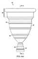
図6Aは、本開示の実施形態による、例示的膣挿入デバイス40の側面図を図示する。図6Aの膣挿入デバイス40は、上側部分42と、下側ステム状除去部分44とを備える。さらに図示および以下により詳細に説明されるように、上側部分42は、リム46と、好ましくは、上側部分の上部から上側部分の下側端まで離間される、隆起48とを含む。隆起48は、ランダムまたは均一に離間されることができる。除去部分もまた、上側部分と同様に、除去部分の上部から除去部分の下側端まで離間される、隆起48を有することができる。 FIG. 6A illustrates a side view of an exemplary
図6Bは、本開示の実施形態による、別の例示的膣挿入デバイス40の側面図を図示する。本実施形態では、デバイス40は、図6Aに示される実施形態と同一であるが、除去部分44は、タンポンを除去する際に使用されるようなストリング、コード、またはリボン(集合的に、「ストリング」と称される)である。 FIG. 6B illustrates a side view of another exemplary
図7は、図6Aの膣挿入デバイス40の斜視図を図示する。図7に示されるように、上側部分42は、円錐形状の本体を有し、その長さ全体を通して円形横断面を有し、内部側50と外部側52を伴う壁49、上側開放端54、下側端56、および中空内部58を有し、上側部分の円周は、上側開放端から下側端へと減少する。図示されるように、リム46は、好ましくは、円形であり、壁の外部側52を囲繞し、そこから突出し、上側開放端54に隣接する。隆起48は、好ましくは、壁49の外部側52を囲繞する、円形リングである。さらに図示されるように、ステムまたは除去部分44は、上側部分42の下側端56から延在する。上側部分42およびステム44は、一体型の1部品から成るデバイスとして加工されることができる。図7はまた、ステム44が円錐形状の本体を有することができることを図示する。 FIG. 7 illustrates a perspective view of the
図8は、切断線A−Aを横断する図6Aの膣挿入デバイス40の断面図である。図8に示されるように、ステム44は、その長さ全体を通して円形横断面を有し、壁60、上側端62、下側開放端64、および中空内部66を有することができ、ステムの円周は、上側端から下側開放端へと増加する。図示されるように、隆起48は、壁49の外部側52から突出する。 FIG. 8 is a cross-sectional view of the
図8はさらに、換気開口部68を含む、膣挿入デバイス40の実施形態を図示する。換気開口部は、換気孔、スクリーン、またはメッシュ、もしくは開口部を伴う任意の他の構成要素を含むことができる。当業者によって理解されるであろうように、膣挿入デバイス40は、上側部分42の壁49内等の換気開口部68以外またはそれに加えた場所にも、複数の換気開口部を含むことができる。1つ以上の換気開口部は、挿入されると、膣挿入デバイスを患者にとってより快適にするように意図される。1つ以上の開口部はまた、膣挿入デバイス40が挿入されると、膣18の内側と外側との間の空気圧を均衡化し得る。しかしながら、換気開口部を有することは、膣挿入デバイスが快適、有用、かつ効果的であるために要求されない。 FIG. 8 further illustrates an embodiment of a
図8は、リム46が、第1の区分70と、第2の区分72とを有する実施形態に関する、さらなる詳細を図示し、両方とも、壁49の外部側52から突出し、第1の区分は、第2の区分の距離を上回って突出する。当業者は、リム46が第1の区分70のみを備える、実施形態、またはリム46が1つのみの区分を備えるが、第1の区分70を上回る高さを有し、リムの上部からリムの底部まで同一距離で壁の外部側52から突出する、別の実施形態を含む、リム46の複数の代替実施形態が可能性として考えられることを理解するであろう。別の実施形態では、リム46は、壁49の外部側52を囲繞し、上側開放端54に隣接し、壁の外部側から突出する区分と、突出しない区分とを備える。 FIG. 8 illustrates further details of an embodiment in which the
図7および8を参照すると、用語「隆起」は、広義に定義されることが意図される。故に、隆起48は、図7および8に図示される実施形態を含むことができ、隆起48は、好ましくは、壁49の外部側を囲繞する円形リングである、突出部である。しかしながら、「隆起」はまた、複数のスタッドまたはノブ等の壁49の外部側52から延在する、任意の突出部を含むことができる。 With reference to FIGS. 7 and 8, the term "raised" is intended to be broadly defined. Thus, the
当業者は、膣挿入デバイス40が、異なる生体構造を伴う成人女性に適応するための異なるサイズを含む、異なるサイズをとることができることを理解するであろう。さらに、当業者は、デバイス40の種々の区分および部分の寸法が、本明細書に図示ならびに開示される複数の実施形態から修正されることができることを理解するであろう。例えば、図8を参照すると、デバイス40の全高74、上側部分42の上側開放端54の直径76、およびデバイス40の上側部分42の壁49の厚さは、デバイスの意図される有用性、有効性、および他の利点を留保または改良しながら、修正されることができる。図8を参照した寸法の以下の非排他的リストは、大部分の女性に好適であると考えられ、デバイスの意図される有用性、有効性、および他の利点を提供する、デバイス40の非限定的実施例である。例えば、デバイス40の好適な全高は、約58.0〜67.0ミリメートル(mm)の範囲内であると推定され、好適な外径76は、約38.0〜44.0mmの範囲内であると推定される。ステム44の好適な高さは、約13.0〜15.0mmの範囲内であると推定される。リム46の下方の上側部分42の隆起48を伴わない区分内の壁49の好適な厚さは、約2.0mmであると推定される一方、隆起を伴う区分内の壁49の好適な厚さは、約2.5mmであると推定される。ステム44の壁60は、隆起48を伴わない区分内に約1.25mmの好適な厚さを有すると推定された。リム46の好適な高さは、約15.0mmであると推定され、第1の区分70の好適な高さは、約5.0mmであると推定され、第2の区分72の好適な高さは、約10.0mmであると推定される。第1の区分70の好適な厚さは、約6.0mmであると推定され、第2の区分72は、約4.0mmであると推定される。下側開放端64の好適な外径82は、約10.5mmであると推定される。換気開口部68の好適な直径は、約2.0mmであると推定される。 Those skilled in the art will appreciate that the
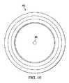
図9は、換気開口部68を有する実施形態のための図6Aの膣挿入デバイス40の底面図である。図10は、換気開口部68を有する実施形態のための図6Aの膣挿入デバイス40の上面図である。 FIG. 9 is a bottom view of the
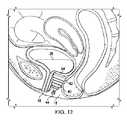
図11は、膣18内に挿入され、圧力を尿道括約筋16に印加し、女性の尿失禁を管理、改善、または排除する、膣挿入デバイス40の実施形態を図示する、女性の骨盤領域の断面である。図12および13はそれぞれ、膣18内に挿入され、圧力を尿道括約筋16に印加し、女性の尿失禁を管理、改善、または排除することに加え、POPを管理、改善、または排除する、膣挿入デバイス40の実施形態を図示する、女性の骨盤領域の断面である。特に、図12では、膣挿入デバイス40は、膣18内に挿入され、膀胱脱26を管理、改善、または排除する。特に、図13では、膣挿入デバイス40は、膣18内に挿入され、子宮脱30を管理、改善、または排除する。図11−13に図示されるように、上側部分42の上側開放端54は、挿入の間、膣挿入デバイス40の最内部分である。図11−13にさらに図示されるように、膣挿入デバイス40の実施形態の除去部分またはステム44は、膣挿入デバイスが挿入されるとき、膣18の外部からアクセスされ、膣挿入デバイスの除去を補助することができる。ステム44上の隆起48は、患者によるデバイス40の除去のためのより良好な把持を提供する。 FIG. 11 illustrates a cross section of a female pelvic region that illustrates an embodiment of a
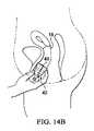
図14Aおよび14Bは、膣挿入デバイス40を膣18の中に快適に挿入するための方法を図示する。図14Aに図示されるように、患者は、膣挿入デバイス40のより容易な挿入のために、上側部分の壁49を手動で圧搾し、上側部分をよりコンパクトにすることができる。図14Bに図示されるように、いったん膣挿入デバイス40が、膣18の中に手動で挿入されると、壁49は、その元の形状に戻るように拡張する。 14A and 14B illustrate a method for comfortably inserting the
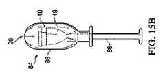
図15Aは、膣挿入デバイス40を患者の膣18の中に挿入する際に補助するために使用され得る、ペッサリアプリケータ84の側面図を図示する。ペッサリアプリケータ84は、挿入部材86と、挿入部材の上部部分90と、プランジャ88とを備える。ペッサリアプリケータ84は、概して、タンポンアプリケータに類似する。しかしながら、挿入部材86は、コンパクト化されると、概して、タンポンの円周より大きい形状を有する、膣挿入デバイス40に適応するために、概して、タンポンアプリケータを上回る円周を有するであろう。図15B−15Cは、図15Aのペッサリアプリケータ84の断面と、アプリケータを使用して、膣挿入デバイス40を患者の膣18の中に快適に挿入する方法とを図示する。図示されるように、膣挿入デバイス40は、コンパクト化された形状において挿入部材86の内側に格納される。アプリケータを使用した膣の中へのタンポンの挿入プロセスと同様に、アプリケータ84の挿入部材86が、患者の膣18の中に挿入され、プランジャ88が、挿入部材に向かって押動され、膣挿入デバイス40を上部部分90を通して吐出する。アプリケータ84は、次いで、膣18から除去され、膣挿入デバイス40は、膣内の定位置に留まり、その通常の形状に戻るように拡張される。挿入された膣挿入デバイス40は、図11に図示されるように位置付けられる。 FIG. 15A illustrates a side view of a
本開示は、当業者が理解するであろう、本明細書における例示的実施形態に対するあらゆる変更、代用、変形例、改変、および修正を包含する。同様に、必要に応じて、添付の請求項も、当業者が理解するであろう、本明細書における例示的実施形態に対するあらゆる変更、代用、変形例、改変、および修正を包含する。さらに、添付の請求項における、装置、デバイス、またはシステム、もしくは装置、デバイス、またはシステムの構成要素、区分、または部分が、特定の機能を行うように適合される、そのように配列される、それが可能である、そのように構成される、そのように可能にされる、そのように動作可能である、またはそのように動作するというような言及は、装置、デバイス、システム、または構成要素が、それまたはその特定の機能にかかわらず、その装置、システム、デバイス、または構成要素が、そのように適合される、そのように配列される、それが可能である、そのように構成される、そのように可能にされる、そのように動作可能である、またはそのように動作する限り、使用される、アクティブ化される、オンにされる、またはロック解除されることを包含する。 The present disclosure includes any modifications, substitutions, variations, modifications, and modifications to the exemplary embodiments herein that will be appreciated by those skilled in the art. Similarly, if necessary, the accompanying claims also include any modifications, substitutions, variations, modifications, and modifications to the exemplary embodiments herein that will be appreciated by those skilled in the art. In addition, the device, device, or system, or component, section, or portion of the device, device, or system in the appended claims is adapted, and so arranged, to perform a particular function. References such as that it is possible, that it is configured, that it is made possible, that it is operational, or that it behaves, are devices, devices, systems, or components. However, regardless of it or its specific function, the device, system, device, or component is so adapted, so arranged, it is possible, so configured. Includes being used, activated, turned on, or unlocked as long as it is so enabled, so operational, or so.
本明細書に列挙される全ての実施例および条件付き用語は、読者が本発明者によって当技術分野に寄与された本開示および概念を理解する補助のための教育目的のために意図され、そのような具体的に列挙された実施例および条件に限定されるものとして解釈されない。本開示の実施形態が、詳細に説明されたが、種々の変化、代用、および改変が、本開示の精神ならびに範囲から逸脱することなく、本明細書に成され得ることを理解されたい。 All examples and conditional terms listed herein are intended for educational purposes to assist the reader in understanding the disclosures and concepts contributed to the art by the present inventor. It is not construed as being limited to such specifically listed examples and conditions. Although embodiments of the present disclosure have been described in detail, it is appreciated that various changes, substitutions, and modifications can be made herein without departing from the spirit and scope of the present disclosure.
Claims (31)
Translated fromJapanese上側部分であって、前記上側部分は、弾性かつ非吸収性の材料から作製され、円錐形状の本体を有し、前記上側部分の長さ全体を通して円形横断面を有し、内部側と外部側とを伴う壁、上側開放端、下側端、および中空内部を有し、前記上側部分の円周は、前記上側開放端から前記下側端へと減少し、前記上側部分の上側開放端は、挿入の間、前記膣挿入デバイスの最内部分であり、前記上側部分の壁は、前記膣挿入デバイスのより容易な挿入のために、前記上側部分をよりコンパクトな形状にするように圧搾されるように構成され、前記壁は、前記挿入後、その元の形状に戻るように拡張する、上側部分と、
前記上側部分の壁の外部側を囲繞し、そこから突出する、外部リムであって、前記外部リムは、前記上側開放端に隣接する、外部リムと、
前記上側部分の壁の外部側を囲繞し、そこから突出する、複数の隆起であって、前記複数の隆起は、前記上側開放端から前記下側端まで離間されており、前記上側部分は、前記デバイスが挿入されると、前記外部リムおよび前記複数の隆起を用いて、前記膣挿入デバイスをしっかりと定位置に保持することにより、圧力を尿道括約筋にかけ、または骨盤臓器を支持し、または圧力を前記尿道括約筋にかけることと、骨盤臓器を支持することとの両方を行う、複数の隆起と、
前記上側部分の前記下側端から延在する除去部分であって、前記除去部分は、前記膣挿入デバイスが膣内に挿入されると、前記膣の外部からアクセスされるように構成され、前記除去部分は、前記膣挿入デバイスの除去を補助する、除去部分と
を備え、
前記膣挿入デバイスは、骨盤臓器脱、尿失禁、または骨盤臓器脱および尿失禁の両方を管理、改善、または排除し、または、前記膣挿入デバイスは、骨盤臓器脱、尿失禁、または骨盤臓器脱および尿失禁の両方と関連付けられた症状を改善する際に使用するためである、膣挿入デバイス。A vaginal insertion device
The upper portion, said upper portion, is made of an elastic and non-absorbable material, has a conical body, has a circular cross section throughout the length of the upper portion, and has an inner side and an outer side. It has a wall with, an upper open end, a lower end, and a hollow interior, the circumference of the upper portion decreases from the upper open end to the lower end, and the upper open end of the upper portion During insertion, the innermost portion of the vaginal insertion device, the wall of the upper portion is squeezed to give the upper portion a more compact shape for easier insertion of the vaginal insertion device. The wall is configured to, after the insertion, expands to return to its original shape, with an upper portion.
An external rim that surrounds and projects from the outer side of the wall of the upper portion, wherein the outer rim is adjacent to the upper open end and the outer rim.
A plurality of ridges that surround and project from the outer side of the wall of the upper portion, the plurality of ridges being separated from the upper open end to the lower end, and the upper portion is: When the device is inserted, pressure is applied to the urethral sphincter or to support or pressure the pelvic organs by holding the vaginal insertion device firmly in place using the external rim and the plurality of ridges. With multiple ridges that both apply to the urethral sphincter and support the pelvic organs.
A removal portion extending from the lower end of the upper portion, the removal portion being configured to be accessed from outside the vagina when the vaginal insertion device is inserted into the vagina. The removal portion comprises a removal portion that assists in the removal of the vaginal insertion device.
The vaginal insertion device manages, improves, or eliminates pelvic organ prolapse, urinary incontinence, or both pelvic organ prolapse and urinary incontinence, or the vaginal insertion device is pelvic organ prolapse, urinary incontinence, or pelvic organ prolapse. And a vaginal insertion device, for use in improving the symptoms associated with both urinary incontinence.
上側部分であって、前記上側部分は、弾性かつ非吸収性の材料から作製され、円錐形状の本体を有し、前記上側部分の長さ全体を通して円形横断面を有し、内部側と外部側とを伴う壁、上側開放端、下側端、および中空内部を有し、前記上側部分の円周は、前記上側開放端から前記下側端へと減少し、前記上側部分の上側開放端は、挿入の間、前記膣挿入デバイスの最内部分であり、前記上側部分の壁は、前記膣挿入デバイスのより容易な挿入のために、前記上側部分をよりコンパクトな形状にするように圧搾されるように構成され、前記壁は、前記挿入後、その元の形状に戻るように拡張する、上側部分と、
前記上側部分の壁の外部側を囲繞し、そこから突出する、外部リムであって、前記外部リムは、前記上側開放端に隣接する、外部リムと、
前記上側部分の壁の外部側を囲繞し、そこから突出する、複数の隆起であって、前記複数の隆起は、前記上側開放端から前記下側端まで離間されており、前記複数の隆起は、前記上側部分の全長に沿って前記下側端から前記外部リムまで分布され、前記上側部分は、前記デバイスが挿入されると、前記外部リムおよび前記複数の隆起を用いて、前記膣挿入デバイスをしっかりと定位置に保持することにより、圧力を尿道括約筋にかけ、または骨盤臓器を支持し、または圧力を前記尿道括約筋にかけることと、骨盤臓器を支持することとの両方を行う、複数の隆起と、
前記上側部分の前記下側端から延在するステムであって、前記上側部分および前記ステムは、前記弾性かつ非吸収性の材料から作製されている、一体型の1部品から成るデバイスを構成し、前記ステムは、前記膣挿入デバイスが膣内に挿入されると、前記膣の外部からアクセスされるように構成され、前記ステムは、前記膣挿入デバイスの除去を補助する、ステムと
を備える、膣挿入デバイス。A vaginal insertion device for use in improving symptoms associated with pelvic organ prolapse, urinary incontinence, or both pelvic organ prolapse and urinary incontinence.
The upper portion, said upper portion, is made of an elastic and non-absorbable material, has a conical body, has a circular cross section throughout the length of the upper portion, and has an inner side and an outer side. It has a wall with, an upper open end, a lower end, and a hollow interior, the circumference of the upper portion decreases from the upper open end to the lower end, and the upper open end of the upper portion During insertion, the innermost portion of the vaginal insertion device, the wall of the upper portion is squeezed to give the upper portion a more compact shape for easier insertion of the vaginal insertion device. The wall is configured to, after the insertion, expands to return to its original shape, with an upper portion.
An external rim that surrounds and projects from the outer side of the wall of the upper portion, wherein the outer rim is adjacent to the upper open end and the outer rim.
A plurality of ridges surrounding the outer side of the wall of the upper portion and projecting from the ridges, the plurality of ridges being separated from the upper open end to the lower end, and the plurality of ridges. The upper portion is distributed from the lower end to the outer rim along the entire length of the upper portion, the upper portion using the outer rim and the plurality of ridges when the device is inserted, the vaginal insertion device. Multiple ridges that apply pressure to the urethral sphincter or support the pelvic organs, or both apply pressure to the urethral sphincter and support the pelvic organs by holding the urethral sphincter firmly in place. When,
A stem extending from the lower end of the upper portion, wherein the upper portion and the stem constitute an integral one-part device made of the elastic and non-absorbable material. The stem is configured to be accessed from outside the vagina when the vaginal insertion device is inserted into the vagina, and the stem comprises a stem that assists in removal of the vaginal insertion device. Vaginal insertion device.
上側部分であって、前記上側部分は、弾性かつ非吸収性かつ生体適合性のシリコーンエラストマ材料から作製され、円錐形状の本体を有し、前記上側部分の長さ全体を通して円形横断面を有し、内部側と外部側とを伴う壁、上側開放端、下側端、および中空内部を有し、前記上側部分の円周は、前記上側開放端から前記下側端へと減少し、前記上側部分の上側開放端は、挿入の間、前記膣挿入デバイスの最内部分であり、前記上側部分の壁は、前記膣挿入デバイスのより容易な挿入のために、前記上側部分をよりコンパクトな形状にするように圧搾されるように構成され、前記壁は、前記挿入後、その元の形状に戻るように拡張する、上側部分と、
前記上側部分の壁の外部側を囲繞し、そこから突出する、外部リムであって、前記外部リムは、前記上側開放端に隣接する、外部リムと、
前記上側部分の壁の外部側を囲繞し、そこから突出する、複数の隆起であって、前記複数の隆起は、前記上側開放端から前記下側端まで離間されており、前記上側部分は、前記デバイスが挿入されると、前記外部リムおよび前記複数の隆起を用いて、前記膣挿入デバイスをしっかりと定位置に保持することにより、圧力を尿道括約筋にかけ、または骨盤臓器を支持し、または圧力を前記尿道括約筋にかけることと、骨盤臓器を支持することとの両方を行う、複数の隆起と、
前記上側部分の前記下側端から延在するステムであって、前記上側部分および前記ステムは、前記弾性かつ非吸収性かつ生体適合性のシリコーンエラストマ材料から作製されている、一体型の1部品から成るデバイスを構成し、前記ステムは、前記膣挿入デバイスが膣内に挿入されると、前記膣の外部からアクセスされるように構成され、前記ステムは、前記膣挿入デバイスの除去を補助する、ステムと、
換気開口部と
を備え、
前記膣挿入デバイスは、前記膣挿入デバイスが挿入されると、前記膣の内側と外側との間の空気圧を均衡化するように構成され、
前記膣挿入デバイスは、骨盤臓器脱、尿失禁、または骨盤臓器脱および尿失禁の両方を管理、改善、または排除し、または、前記膣挿入デバイスは、骨盤臓器脱、尿失禁、または骨盤臓器脱および尿失禁の両方と関連付けられた症状を改善する際に使用するためである、膣挿入デバイス。A vaginal insertion device
The upper portion, said upper portion, is made of an elastic, non-absorbableand biocompatible silicone elastoma material, has a conical body and has a circular cross section throughout the length of the upper portion. Has a wall with an inner side and an outer side, an upper open end, a lower end, and a hollow interior, the circumference of the upper portion decreases from the upper open end to the lower end and said upper. The upper open end of the portion is the innermost portion of the vaginal insertion device during insertion, and the wall of the upper portion shapes the upper portion into a more compact shape for easier insertion of the vaginal insertion device. The wall is configured to be squeezed so that, after the insertion, the wall expands to return to its original shape, with an upper portion.
An external rim that surrounds and projects from the outer side of the wall of the upper portion, wherein the outer rim is adjacent to the upper open end and the outer rim.
A plurality of ridges that surround and project from the outer side of the wall of the upper portion, the plurality of ridges being separated from the upper open end to the lower end, and the upper portion is: When the device is inserted, pressure is applied to the urethral sphincter or to support or pressure the pelvic organs by holding the vaginal insertion device firmly in place using the external rim and the plurality of ridges. With multiple ridges that both apply to the urethral sphincter and support the pelvic organs.
A stem extending from the lower end of the upper portion, the upper portion and the stem being an integral part made from theelastic, non-absorbable and biocompatible siliconeelastomer material. The stem comprises a device comprising, the stem is configured to be accessed from outside the vagina when the vaginal insertion device is inserted into the vagina, and the stem assists in removal of the vaginal insertion device. , Stem and
With ventilation openings,
The vaginal insertion device is configured to balance the air pressure between the inside and outside of the vagina when the vaginal insertion device is inserted.
The vaginal insertion device manages, improves, or eliminates pelvic organ prolapse, urinary incontinence, or both pelvic organ prolapse and urinary incontinence, or the vaginal insertion device is pelvic organ prolapse, urinary incontinence, or pelvic organ prolapse. And a vaginal insertion device, for use in improving the symptoms associated with both urinary incontinence.
Applications Claiming Priority (5)
| Application Number | Priority Date | Filing Date | Title |
|---|---|---|---|
| US201562283092P | 2015-08-20 | 2015-08-20 | |
| US62/283,092 | 2015-08-20 | ||
| PCT/US2016/047859WO2017031456A1 (en) | 2015-08-20 | 2016-08-19 | Flexible cone-shaped intra-vaginal support device |
| US15/242,105US10188545B2 (en) | 2015-08-20 | 2016-08-19 | Flexible cone-shaped intra-vaginal support device |
| US15/242,105 | 2016-08-19 |
Publications (3)
| Publication Number | Publication Date |
|---|---|
| JP2018526169A JP2018526169A (en) | 2018-09-13 |
| JP2018526169A5 JP2018526169A5 (en) | 2019-10-03 |
| JP6872547B2true JP6872547B2 (en) | 2021-05-19 |
Family
ID=58052020
Family Applications (1)
| Application Number | Title | Priority Date | Filing Date |
|---|---|---|---|
| JP2018528215AActiveJP6872547B2 (en) | 2015-08-20 | 2016-08-19 | Flexible conical intravaginal support device |
Country Status (11)
| Country | Link |
|---|---|
| US (3) | US10188545B2 (en) |
| JP (1) | JP6872547B2 (en) |
| KR (1) | KR102710432B1 (en) |
| CN (1) | CN108135732B (en) |
| AU (2) | AU2016308363B2 (en) |
| BR (1) | BR112018003317B1 (en) |
| CA (1) | CA2996163C (en) |
| IL (1) | IL257627B (en) |
| MX (2) | MX2018002175A (en) |
| RU (2) | RU2020117130A (en) |
| WO (1) | WO2017031456A1 (en) |
Families Citing this family (29)
| Publication number | Priority date | Publication date | Assignee | Title |
|---|---|---|---|---|
| JP6872547B2 (en) | 2015-08-20 | 2021-05-19 | ワトキンス−コンティ プロダクツ, インコーポレイテッド | Flexible conical intravaginal support device |
| CN105147457B (en)* | 2015-08-25 | 2018-09-21 | 广州天沅硅胶机械科技有限公司 | A kind of collapsible menstrual cup |
| US10806624B2 (en) | 2016-11-18 | 2020-10-20 | Lady Business LLC | Menstrual cups and related methods |
| WO2018140192A1 (en) | 2017-01-24 | 2018-08-02 | Liv Labs Inc. | Stress urinary incontinence (sui) device |
| US20180256389A1 (en)* | 2017-03-10 | 2018-09-13 | Coopersurgical, Inc. | Pelvic organ support devices and related methods |
| ES2684068B2 (en)* | 2017-03-28 | 2019-03-05 | Univ Catalunya Politecnica | CONTAINER FOR MENSTRUAL RETENTION AND EMPTYING |
| US11266522B2 (en) | 2017-08-17 | 2022-03-08 | Sally Ann Meyer | Pessary |
| US11185438B2 (en) | 2017-09-26 | 2021-11-30 | Reia, Llc | Pessary for pelvic organ prolapse |
| US11491047B2 (en) | 2017-09-26 | 2022-11-08 | Reia, Llc | Pessary for pelvic organ prolapse |
| US11903869B2 (en) | 2017-09-26 | 2024-02-20 | Reia, Llc | Easily removable pessary device |
| US11865033B2 (en) | 2017-09-26 | 2024-01-09 | Reia, Llc | Vaginal pessary device for pelvic organ prolapse with improved collapsible construction |
| USD832438S1 (en)* | 2017-11-06 | 2018-10-30 | Lady Business LLC | Menstrual cup |
| USD841808S1 (en)* | 2017-11-13 | 2019-02-26 | Elizabeth Drach | Menstrual cup |
| US20190209364A1 (en)* | 2018-01-09 | 2019-07-11 | Likai Jin | Female condom |
| US11291535B2 (en) | 2018-03-16 | 2022-04-05 | Watkins-Conti Products, Inc. | Intravaginal support devices and methods |
| US20200078209A1 (en)* | 2018-09-07 | 2020-03-12 | The Procter & Gamble Company | Menstrual Cup |
| US20200078208A1 (en)* | 2018-09-07 | 2020-03-12 | The Procter & Gamble Company | Menstrual Cup |
| KR102159602B1 (en)* | 2019-02-14 | 2020-09-24 | 박기준 | Menses cup |
| US20200375788A1 (en)* | 2019-05-13 | 2020-12-03 | Christy J. Zhang | Menstrual cup with longitudinal ribbing |
| AU2020203327A1 (en)* | 2019-05-24 | 2020-12-10 | James Edward Clappers | A bladder device for light bladder leakage |
| US20210113363A1 (en)* | 2019-10-21 | 2021-04-22 | Courtney Rose Evans | Menstrual cup with structural features |
| USD923785S1 (en)* | 2019-10-29 | 2021-06-29 | Di Cheng Rubber Industries Inc | Menstrual cup |
| TWI761741B (en)* | 2019-12-18 | 2022-04-21 | 鄔德恕 | Moon cup, moon cup auxiliary device and moon cup combination |
| US11723789B2 (en)* | 2020-02-28 | 2023-08-15 | Charise D. Ramos | Apparatus and methods of using an intra-vaginal fluid collection device |
| WO2021175837A1 (en)* | 2020-03-03 | 2021-09-10 | Deodoc Ab | Urine incontinence device for women |
| CA3178117A1 (en)* | 2020-05-21 | 2021-11-25 | Watkins-Conti Products, Inc. | Vaginal insert devices and methods |
| RU207256U1 (en)* | 2021-03-11 | 2021-10-20 | Вячеслав Михайлович Болотских | Obstetric Sacralizing Pessary Modified |
| US11931288B2 (en)* | 2021-05-21 | 2024-03-19 | Carolyn P. SMULLIN | Collapsible intravaginal cups |
| USD1071181S1 (en) | 2022-04-20 | 2025-04-15 | Liv Labs Inc. | Urinary incontinence device |
Family Cites Families (94)
| Publication number | Priority date | Publication date | Assignee | Title |
|---|---|---|---|---|
| US1996242A (en)* | 1933-03-11 | 1935-04-02 | Kate Woodburn | Catamenial receptacle |
| US2089113A (en) | 1935-07-11 | 1937-08-03 | Leona W Chalmers | Catamenial appliance |
| US2613670A (en) | 1947-04-19 | 1952-10-14 | Sokolik Edward | Sanitary vaginal appliance |
| US2638093A (en) | 1949-12-20 | 1953-05-12 | Kulick George | Vaginal insert |
| US2534900A (en)* | 1950-01-04 | 1950-12-19 | Leona W Chalmers | Menstrual cup |
| US2763265A (en) | 1954-12-14 | 1956-09-18 | Edward G Waters | Gynecological instrument |
| US3404682A (en)* | 1965-11-17 | 1968-10-08 | Tassette Inc | Vaginal cup and means for inserting same |
| US3626942A (en) | 1970-06-02 | 1971-12-14 | Tassette Inc | Vaginal cup having radially arranged internal supporting ribs |
| SE363734B (en)* | 1972-06-09 | 1974-02-04 | Moelnlycke Ab | |
| USD250049S (en) | 1977-08-05 | 1978-10-24 | The Procter & Gamble Company | Outer tube for a tampon inserter |
| US4286593A (en) | 1980-05-05 | 1981-09-01 | Place Virgil A | Vaginal contraceptive shield |
| USD306347S (en) | 1986-11-19 | 1990-02-27 | Smithkline Beckman Corporation | Delayed action dosage unit for releasing medicaments or the like in ruminants |
| USD323212S (en) | 1989-06-30 | 1992-01-14 | The Keeper Co., Inc. | Menstrual cup |
| DK0504301T3 (en) | 1989-12-07 | 2004-05-03 | Instead Inc | Procedure for collecting vaginal secretion |
| US5295984A (en)* | 1989-12-07 | 1994-03-22 | Ultrafem, Inc. | Vaginal discharge collection device and intravaginal drug delivery system |
| US5827248A (en)* | 1993-11-18 | 1998-10-27 | The Keeper Co., Inc. | Menstrual cup |
| US6540728B2 (en) | 1995-02-21 | 2003-04-01 | Filiberto P. Zadini | Inflatable menstrual cup for blood leakage prevention |
| US5782745A (en) | 1995-11-13 | 1998-07-21 | Benderev; Theodore V. | Devices and methods for assessment and treatment of urinary and fecal incontinence |
| AU750463B2 (en) | 1997-03-20 | 2002-07-18 | Niquoola Pty. Ltd. | An intra-vaginal device |
| PL186960B1 (en)* | 1998-05-04 | 2004-04-30 | Adamed Sp Z Oo | Intravaginal set and therapeutic method employing that set |
| USD430669S (en) | 1999-07-21 | 2000-09-05 | The Procter & Gamble Company | Tampon applicator |
| US6170484B1 (en) | 2000-03-10 | 2001-01-09 | Du Xiong Feng | Female contraceptive device |
| GB0017033D0 (en) | 2000-07-12 | 2000-08-30 | Pendry Carole | Inco-stop |
| US6503190B1 (en)* | 2000-09-29 | 2003-01-07 | Ethicon Endo-Surgery, Inc. | Vaginal pessary |
| US6558370B2 (en) | 2001-06-05 | 2003-05-06 | Kimberly-Clark Worldwide, Inc. | Urinary incontinence device |
| US7577476B2 (en) | 2001-10-26 | 2009-08-18 | Athena Feminine Technologies, Inc | System and method for transducing, sensing, or affecting vaginal or body conditions, and/or stimulating perineal musculature and nerves using 2-way wireless communications |
| US6773421B2 (en) | 2001-12-14 | 2004-08-10 | Kimberly-Clark Worlwide, Inc. | Combination for managing the involuntary loss of bladder control |
| CA2371974C (en) | 2002-02-15 | 2003-05-13 | Farrell Medical Incorporated | Incontinence inhibiting or prevention device |
| US6770025B2 (en) | 2002-09-18 | 2004-08-03 | Kimberly-Clark Worldwide, Inc. | Molar shaped vaginal incontinence insert |
| US6733438B1 (en) | 2002-12-23 | 2004-05-11 | Jeffrey Dann | Female stimulation device |
| WO2004103213A1 (en) | 2003-05-22 | 2004-12-02 | Contipi Ltd. | Device for the prevention of urinary incontinence in females |
| MXPA06010653A (en)* | 2004-03-18 | 2007-03-26 | Contipi Ltd | Apparatus for the prevention of urinary incontinence in females. |
| WO2005087153A2 (en) | 2004-03-18 | 2005-09-22 | Contipi Ltd. | Apparatus for the treatment of feminine pelvic organ prolapse |
| EP1796608A4 (en)* | 2004-09-23 | 2008-03-12 | Diva Internat Inc | Menstrual cup |
| IL176883A (en)* | 2005-09-22 | 2013-09-30 | Eliahu Eliachar | Apparatus for the amelioration of urinary incontinence in females |
| US7628156B2 (en) | 2005-10-25 | 2009-12-08 | Ethicon Inc. | Adjustable vaginal splint for pelvic floor support |
| AU2006100036A4 (en)* | 2006-01-17 | 2006-02-23 | Baslar Pty Ltd | Vaginal Cup |
| GB2435215B (en) | 2006-02-17 | 2011-08-03 | Gaynor Morgan | Vaginal device |
| US7717892B2 (en) | 2006-07-10 | 2010-05-18 | Mcneil-Ppc, Inc. | Method of treating urinary incontinence |
| WO2008079271A1 (en)* | 2006-12-21 | 2008-07-03 | Baystate Health, Inc. | Vaginal pessary |
| US20080167599A1 (en)* | 2007-01-10 | 2008-07-10 | The Procter & Gamble Comapny | Active applicator |
| ES1064610Y (en) | 2007-01-11 | 2007-07-01 | Zainuddin Dawoodi | CASE SUITABLE TO CONTAIN A LAST BODY OF REINFORCEMENT OF THE MUSCULATURE OF THE PELVIC SOIL FOR THE TREATMENT OF URINARY INCONTINENCE |
| US20090095304A1 (en)* | 2007-10-15 | 2009-04-16 | Sharon Ann Richardson | Vaginal pessary for the management of stress incontinence |
| US8449446B2 (en) | 2008-02-06 | 2013-05-28 | Contipi Ltd. | Female urinary incontinence devices |
| SE533048C2 (en) | 2008-04-11 | 2010-06-15 | Charlotte Norman | Menstrual protection for multiple use. |
| US8651109B2 (en)* | 2008-04-23 | 2014-02-18 | Contipi Ltd. | Pessaries for prolapse alleviation |
| US10463530B2 (en)* | 2008-08-15 | 2019-11-05 | Viatechmd Llc | Cervical stabilization device |
| US10729464B1 (en)* | 2008-08-15 | 2020-08-04 | Viatechmd Llc | Cervical stabilization device |
| SE533404C2 (en) | 2008-12-22 | 2010-09-14 | Invent Medic Sweden Ab | Vaginal device for preventing strain incontinence |
| US20100312204A1 (en)* | 2009-06-06 | 2010-12-09 | Miin-Tsang Sheu | Menstrual Cup Device and Method of Use Thereof |
| DE202009008893U1 (en)* | 2009-06-29 | 2009-10-01 | Krüger, Julia | Device for collecting menstrual fluid |
| KR100973524B1 (en) | 2009-07-27 | 2010-08-02 | (주)그린실리콘 | Insertion type sanitary cup |
| US20110105830A1 (en) | 2009-10-30 | 2011-05-05 | Mari Hou | Applicator for Self-Expanding Intravaginal Urinary Incontinence Devices |
| US8652026B2 (en) | 2009-12-31 | 2014-02-18 | Kimberly-Clark Worldwide, Inc. | Disposable urine incontinence device |
| JP5371825B2 (en)* | 2010-02-19 | 2013-12-18 | 賢治 石井 | pessary |
| WO2011141866A2 (en) | 2010-05-13 | 2011-11-17 | Noel Elman | Stent devices for support, controlled drug delivery and pain management after vaginal surgery |
| WO2012006670A1 (en) | 2010-07-13 | 2012-01-19 | Contiform International Pty Ltd | Intra-vaginal incontinence device and an applicator for same |
| CN201949183U (en)* | 2010-07-19 | 2011-08-31 | 李玮玲 | Stress urinary incontinence treating apparatus |
| USD655415S1 (en) | 2010-08-13 | 2012-03-06 | Bernard Chaffringeon | Hygiene article |
| US9022919B2 (en) | 2010-12-23 | 2015-05-05 | Kimberly-Clark Worldwide, Inc. | Vaginal insert device having a support portion with plurality of struts |
| US9814630B2 (en)* | 2010-12-23 | 2017-11-14 | Kimberly-Clark Worldwide, Inc. | Vaginal insert device having a support portion with plurality of foldable areas |
| US8926493B2 (en) | 2011-04-11 | 2015-01-06 | The Procter & Gamble Company | Pessary device |
| US20120259167A1 (en) | 2011-04-11 | 2012-10-11 | Nancy Karapasha | Single use pessary devices |
| USD661390S1 (en) | 2011-06-13 | 2012-06-05 | Mclain Cory | Foreskin extender |
| USD661392S1 (en) | 2011-06-13 | 2012-06-05 | Mclain Cory | Foreskin extender |
| JP2014530678A (en) | 2011-09-22 | 2014-11-20 | ペルヴァロン・インコーポレイテッド | Intravaginal device and method for treating fecal incontinence |
| ES2635737T3 (en)* | 2011-10-04 | 2017-10-04 | Gynamics Women's Health Ltd. | Device for female urinary incontinence |
| US8795248B2 (en) | 2011-10-31 | 2014-08-05 | Alfred A. Shihata | Device and method for menstrual blood collection |
| US8911344B2 (en) | 2011-12-20 | 2014-12-16 | Kimberly-Clark Worldwide, Inc. | Vaginal insert device having perpendicular segments |
| IL217568A0 (en) | 2012-01-16 | 2012-03-29 | Meytal Bouhadana | Multipurpose catamenial device |
| JP3177410U (en)* | 2012-05-21 | 2012-08-02 | 瑞枝 山田 | Pelvic organ prolapse prevention tool |
| US9320640B2 (en)* | 2012-06-29 | 2016-04-26 | The Procter & Gamble Company | Method of attaching a withdrawal member to a pessary device |
| US8919345B2 (en)* | 2012-06-29 | 2014-12-30 | Robert Clark Avery, Jr. | Method of overwrapping a pessary device |
| FR2993773B1 (en) | 2012-07-24 | 2018-02-23 | Giorgio Coretti | APPARATUS FOR COLLECTING MENSTRUATIONS, MENSTRUAL CUP WITH APPLICATOR |
| US9439748B2 (en)* | 2012-10-10 | 2016-09-13 | The Procter & Gamble Company | Pessary device |
| US9339364B2 (en)* | 2012-10-10 | 2016-05-17 | The Procter & Gamble Company | Intravaginal device withdrawal assembly |
| RU129391U1 (en)* | 2012-11-20 | 2013-06-27 | Геннадий Тихонович Сухих | UROGYNOLOGICAL PESSARY |
| WO2014162363A1 (en)* | 2013-04-05 | 2014-10-09 | テルモ株式会社 | Intravaginal support tool and fluid injection device |
| JPWO2015041353A1 (en)* | 2013-09-20 | 2017-03-02 | 潤子 八木 | Ring pessary for uterine prolapse or uterine droop treatment |
| USD767759S1 (en) | 2014-06-20 | 2016-09-27 | Christine McMillon-Nixon | Feminine hygiene mini-dispenser |
| USD717950S1 (en) | 2014-08-10 | 2014-11-18 | Thinx, LLC | Reusable tampon applicator |
| USD719653S1 (en) | 2014-08-10 | 2014-12-16 | Thinx, LLC | Reusable tampon applicator |
| USD760897S1 (en) | 2014-09-25 | 2016-07-05 | Ai Chen Teo | Menstrual cup |
| USD746452S1 (en) | 2015-01-16 | 2015-12-29 | Vilislava Petrova | Reusable menstrual cup |
| WO2016149317A1 (en) | 2015-03-19 | 2016-09-22 | Restore Health, Inc. | Treatment for vesicovaginal fistula |
| US10016308B2 (en)* | 2015-03-26 | 2018-07-10 | Chante' Knox | Absorbent menstrual cup |
| WO2017015767A1 (en) | 2015-07-29 | 2017-02-02 | Standard Innovation Corporation | Device and method for monitoring feminine hygiene |
| USD741479S1 (en) | 2015-08-10 | 2015-10-20 | Thinx, Inc. | Reusable tampon applicator |
| JP6872547B2 (en) | 2015-08-20 | 2021-05-19 | ワトキンス−コンティ プロダクツ, インコーポレイテッド | Flexible conical intravaginal support device |
| ITUB20159804A1 (en)* | 2015-12-30 | 2017-06-30 | Laura Maria Rolandi | DEVICE FOR SUPPORTING THE VAGINAL WALL |
| WO2018222728A1 (en) | 2017-05-31 | 2018-12-06 | 4Women Health, Inc. | Self-collection device and kit for collecting cervical and vaginal cells |
| DE202017106300U1 (en) | 2017-10-18 | 2017-10-25 | Taiwan Innova Efficiency Inc. | Long-term menstrual cup |
| KR101961471B1 (en) | 2018-05-09 | 2019-03-25 | 주식회사 룬랩 | Back-flow prevention cap for menstrual cup and menstrual cup comprising the same |
| US20200078208A1 (en) | 2018-09-07 | 2020-03-12 | The Procter & Gamble Company | Menstrual Cup |
- 2016
- 2016-08-19JPJP2018528215Apatent/JP6872547B2/enactiveActive
- 2016-08-19WOPCT/US2016/047859patent/WO2017031456A1/ennot_activeCeased
- 2016-08-19RURU2020117130Apatent/RU2020117130A/enunknown
- 2016-08-19CNCN201680048687.3Apatent/CN108135732B/enactiveActive
- 2016-08-19USUS15/242,105patent/US10188545B2/enactiveActive
- 2016-08-19MXMX2018002175Apatent/MX2018002175A/enunknown
- 2016-08-19KRKR1020187007430Apatent/KR102710432B1/enactiveActive
- 2016-08-19RURU2018109509Apatent/RU2722444C2/enactive
- 2016-08-19AUAU2016308363Apatent/AU2016308363B2/enactiveActive
- 2016-08-19BRBR112018003317-0Apatent/BR112018003317B1/enactiveIP Right Grant
- 2016-08-19CACA2996163Apatent/CA2996163C/enactiveActive
- 2018
- 2018-02-20MXMX2023007043Apatent/MX2023007043A/enunknown
- 2018-02-20ILIL257627Apatent/IL257627B/enactiveIP Right Grant
- 2018-12-18USUS16/224,566patent/US11219548B2/enactiveActive
- 2020
- 2020-09-11AUAU2020230321Apatent/AU2020230321A1/ennot_activeAbandoned
- 2021
- 2021-11-19USUS17/531,264patent/US20220071800A1/enactivePending
Also Published As
| Publication number | Publication date |
|---|---|
| NZ740253A (en) | 2023-12-22 |
| KR20180054612A (en) | 2018-05-24 |
| US11219548B2 (en) | 2022-01-11 |
| US20190117443A1 (en) | 2019-04-25 |
| US20170049609A1 (en) | 2017-02-23 |
| RU2018109509A (en) | 2019-09-23 |
| RU2722444C2 (en) | 2020-06-01 |
| JP2018526169A (en) | 2018-09-13 |
| CA2996163C (en) | 2023-10-24 |
| AU2020230321A1 (en) | 2020-10-01 |
| RU2020117130A (en) | 2020-06-17 |
| HK1255813A1 (en) | 2019-08-30 |
| IL257627A (en) | 2018-04-30 |
| RU2018109509A3 (en) | 2019-12-06 |
| KR102710432B1 (en) | 2024-09-25 |
| CN108135732B (en) | 2020-08-14 |
| IL257627B (en) | 2021-06-30 |
| MX2018002175A (en) | 2018-09-12 |
| AU2016308363A1 (en) | 2018-03-22 |
| BR112018003317A2 (en) | 2018-09-18 |
| MX2023007043A (en) | 2023-06-23 |
| US20220071800A1 (en) | 2022-03-10 |
| BR112018003317B1 (en) | 2023-02-28 |
| HK1256629A1 (en) | 2019-09-27 |
| WO2017031456A1 (en) | 2017-02-23 |
| AU2016308363B2 (en) | 2020-08-27 |
| CN108135732A (en) | 2018-06-08 |
| US10188545B2 (en) | 2019-01-29 |
| CA2996163A1 (en) | 2017-02-23 |
Similar Documents
| Publication | Publication Date | Title |
|---|---|---|
| JP6872547B2 (en) | Flexible conical intravaginal support device | |
| US12127926B2 (en) | Intravaginal support devices and methods | |
| de Sousa Marques et al. | Creation of a neovagina in patients with Rokitansky syndrome using peritoneum from the pouch of Douglas: an analysis of 48 cases | |
| EP3337434B1 (en) | Flexible cone-shaped intra-vaginal support device | |
| HK1256629B (en) | Flexible cone-shaped intra-vaginal support device | |
| HK1255813B (en) | Flexible cone-shaped intra-vaginal support device | |
| HK40040292A (en) | Vaginal insert device | |
| HK40040292B (en) | Vaginal insert device | |
| Culligan | Pessay Devices: A Stepwise Approach to Fitting, Teaching, and Managing |
Legal Events
| Date | Code | Title | Description |
|---|---|---|---|
| A521 | Request for written amendment filed | Free format text:JAPANESE INTERMEDIATE CODE: A523 Effective date:20190819 | |
| A621 | Written request for application examination | Free format text:JAPANESE INTERMEDIATE CODE: A621 Effective date:20190819 | |
| A977 | Report on retrieval | Free format text:JAPANESE INTERMEDIATE CODE: A971007 Effective date:20200622 | |
| A131 | Notification of reasons for refusal | Free format text:JAPANESE INTERMEDIATE CODE: A131 Effective date:20200727 | |
| A521 | Request for written amendment filed | Free format text:JAPANESE INTERMEDIATE CODE: A523 Effective date:20201027 | |
| TRDD | Decision of grant or rejection written | ||
| A01 | Written decision to grant a patent or to grant a registration (utility model) | Free format text:JAPANESE INTERMEDIATE CODE: A01 Effective date:20210329 | |
| A61 | First payment of annual fees (during grant procedure) | Free format text:JAPANESE INTERMEDIATE CODE: A61 Effective date:20210419 | |
| R150 | Certificate of patent or registration of utility model | Ref document number:6872547 Country of ref document:JP Free format text:JAPANESE INTERMEDIATE CODE: R150 | |
| S531 | Written request for registration of change of domicile | Free format text:JAPANESE INTERMEDIATE CODE: R313531 | |
| R350 | Written notification of registration of transfer | Free format text:JAPANESE INTERMEDIATE CODE: R350 | |
| R250 | Receipt of annual fees | Free format text:JAPANESE INTERMEDIATE CODE: R250 | |
| R250 | Receipt of annual fees | Free format text:JAPANESE INTERMEDIATE CODE: R250 |