JP6872298B2 - device - Google Patents
deviceDownload PDFInfo
- Publication number
- JP6872298B2 JP6872298B2JP2017549752AJP2017549752AJP6872298B2JP 6872298 B2JP6872298 B2JP 6872298B2JP 2017549752 AJP2017549752 AJP 2017549752AJP 2017549752 AJP2017549752 AJP 2017549752AJP 6872298 B2JP6872298 B2JP 6872298B2
- Authority
- JP
- Japan
- Prior art keywords
- heat exchange
- tube
- bag
- working fluid
- frame
- Prior art date
- Legal status (The legal status is an assumption and is not a legal conclusion. Google has not performed a legal analysis and makes no representation as to the accuracy of the status listed.)
- Active
Links
Images


Classifications
- A—HUMAN NECESSITIES
- A61—MEDICAL OR VETERINARY SCIENCE; HYGIENE
- A61F—FILTERS IMPLANTABLE INTO BLOOD VESSELS; PROSTHESES; DEVICES PROVIDING PATENCY TO, OR PREVENTING COLLAPSING OF, TUBULAR STRUCTURES OF THE BODY, e.g. STENTS; ORTHOPAEDIC, NURSING OR CONTRACEPTIVE DEVICES; FOMENTATION; TREATMENT OR PROTECTION OF EYES OR EARS; BANDAGES, DRESSINGS OR ABSORBENT PADS; FIRST-AID KITS
- A61F7/00—Heating or cooling appliances for medical or therapeutic treatment of the human body
- A61F7/12—Devices for heating or cooling internal body cavities
- A—HUMAN NECESSITIES
- A61—MEDICAL OR VETERINARY SCIENCE; HYGIENE
- A61F—FILTERS IMPLANTABLE INTO BLOOD VESSELS; PROSTHESES; DEVICES PROVIDING PATENCY TO, OR PREVENTING COLLAPSING OF, TUBULAR STRUCTURES OF THE BODY, e.g. STENTS; ORTHOPAEDIC, NURSING OR CONTRACEPTIVE DEVICES; FOMENTATION; TREATMENT OR PROTECTION OF EYES OR EARS; BANDAGES, DRESSINGS OR ABSORBENT PADS; FIRST-AID KITS
- A61F7/00—Heating or cooling appliances for medical or therapeutic treatment of the human body
- A61F7/0085—Devices for generating hot or cold treatment fluids
- A—HUMAN NECESSITIES
- A61—MEDICAL OR VETERINARY SCIENCE; HYGIENE
- A61F—FILTERS IMPLANTABLE INTO BLOOD VESSELS; PROSTHESES; DEVICES PROVIDING PATENCY TO, OR PREVENTING COLLAPSING OF, TUBULAR STRUCTURES OF THE BODY, e.g. STENTS; ORTHOPAEDIC, NURSING OR CONTRACEPTIVE DEVICES; FOMENTATION; TREATMENT OR PROTECTION OF EYES OR EARS; BANDAGES, DRESSINGS OR ABSORBENT PADS; FIRST-AID KITS
- A61F7/00—Heating or cooling appliances for medical or therapeutic treatment of the human body
- A61F2007/0054—Heating or cooling appliances for medical or therapeutic treatment of the human body with a closed fluid circuit, e.g. hot water
- A61F2007/0056—Heating or cooling appliances for medical or therapeutic treatment of the human body with a closed fluid circuit, e.g. hot water for cooling
- A—HUMAN NECESSITIES
- A61—MEDICAL OR VETERINARY SCIENCE; HYGIENE
- A61F—FILTERS IMPLANTABLE INTO BLOOD VESSELS; PROSTHESES; DEVICES PROVIDING PATENCY TO, OR PREVENTING COLLAPSING OF, TUBULAR STRUCTURES OF THE BODY, e.g. STENTS; ORTHOPAEDIC, NURSING OR CONTRACEPTIVE DEVICES; FOMENTATION; TREATMENT OR PROTECTION OF EYES OR EARS; BANDAGES, DRESSINGS OR ABSORBENT PADS; FIRST-AID KITS
- A61F7/00—Heating or cooling appliances for medical or therapeutic treatment of the human body
- A61F7/12—Devices for heating or cooling internal body cavities
- A61F2007/126—Devices for heating or cooling internal body cavities for invasive application, e.g. for introducing into blood vessels
Landscapes
- Health & Medical Sciences (AREA)
- Animal Behavior & Ethology (AREA)
- Veterinary Medicine (AREA)
- Engineering & Computer Science (AREA)
- Biomedical Technology (AREA)
- Heart & Thoracic Surgery (AREA)
- Vascular Medicine (AREA)
- Public Health (AREA)
- General Health & Medical Sciences (AREA)
- Life Sciences & Earth Sciences (AREA)
- Thermal Sciences (AREA)
- Physics & Mathematics (AREA)
- Infusion, Injection, And Reservoir Apparatuses (AREA)
- External Artificial Organs (AREA)
- Thermotherapy And Cooling Therapy Devices (AREA)
- Reciprocating Pumps (AREA)
Description
Translated fromJapanese本願は、概して、作動流体カセットを用いる患者の体温制御用の熱交換システムに関する。 The present application generally relates to a heat exchange system for controlling a patient's body temperature using a working fluid cassette.
患者の体温制御システムが、くも膜下出血、又は脳卒中のような他の神経系疾患に罹患することに起因する、神経系ICUの患者の発熱を予防するために導入されている。また、そのようなシステムは、脳卒中、心停止、心筋梗塞、外傷性脳損傷、及び高頭蓋内圧などのような疾患を罹患した患者の転帰を改善するために、軽度又は中度の低体温を誘発するためにも使用されている。血管内の熱交換カテーテルの例は、米国特許第7,914,564号、第6,416,533号、第6,409,747号、第6,405,080号、第6,393,320号、第6,368,304号、第6,338,727号、第6,299,599号、第6,290,717号、第6,287,326号、第6,165,207号、第6,149,670号、第6,146,411号、第6,126,684号、第6,306,161号、第6,264,679号、第6,231,594号、第6,149,676号、第6,149,673号、第6,110,168号、第5,989,238号、第5,879,329号、第5,837,003号、第6,383,210号、第6,379,378号、第6,364,899号、第6,325,818号、第6,312,452号、第6,261,312号、第6,254,626号、第6,251,130号、第6,251,129号、第6,245,095号、第6,238,428号、第6,235,048号、第6,231,595号、第6,224,624号、第6,149,677号、第6,096,068号、第6,042,559号、第8,888,729号、及び米国特許公開第2013/0178923号、第2013/0079855号、第2013/0079856号、第2014/0094880号、第2014/0094882号、第2014/0094883号に開示されており、これらすべてが、参照により本明細書に組み込まれる。 A patient's temperature control system has been introduced to prevent fever in patients with a nervous system ICU due to suffering from subarachnoid hemorrhage or other nervous system disorders such as stroke. Such systems also provide mild or moderate hypothermia to improve outcomes in patients suffering from diseases such as stroke, cardiac arrest, myocardial infarction, traumatic brain injury, and high intracranial pressure. It is also used to induce. Examples of intravascular heat exchange catheters are US Pat. Nos. 7,914,564, 6,416,533, 6,409,747, 6,405,080, 6,393,320. Nos. 6,368,304, 6,338,727, 6,299,599, 6,290,717, 6,287,326, 6,165,207, No. 6,149,670, No. 6,146,411, No. 6,126,684, No. 6,306,161, No. 6,264,679, No. 6,231,594, No. 6 , 149,676, 6,149,673, 6,110,168, 5,989,238, 5,879,329, 5,837,003, 6,383 , 210, 6,379,378, 6,364,899, 6,325,818, 6,321,452, 6,261,312, 6,254,626 Nos. 6,251,130, 6,251,129, 6,245,095, 6,238,428, 6,235,048, 6,231,595, No. 6,224,624, No. 6,149,677, No. 6,096,068, No. 6,042,559, No. 8,888,729, and U.S. Patent Publication No. 2013/0178923, 2013/0079855, 2013/0079585, 2014/0094880, 2014/0094882, 2014/0094883, all of which are incorporated herein by reference.
外部患者体温制御システムが使用され得る。そのようなシステムは、米国特許第6,827,728号、第6,818,012号、第6,802,855号、第6,799,063号、第6,764,391号、第6,692,518号、第6,669,715号、第6,660,027号、第6,648,905号、第6,645,232号、第6,620,187号、第6,461,379号、第6,375,674号、第6,197,045号、及び第6,188,930号(総称して「外部パッド特許」)に開示されており、これらすべてが、参照により本明細書に組み込まれる。 An external patient temperature control system can be used. Such systems are described in US Pat. Nos. 6,827,728, 6,818,012, 6,802,855, 6,799,063, 6,764,391, 6. , 692,518, 6,669,715, 6,660,027, 6,648,905, 6,645,232, 6,620,187, 6,461 , 379, 6,375,674, 6,197,045, and 6,188,930 (collectively, "external pad patents"), all of which are by reference. Incorporated herein.
概して、血管内の温度制御及び外部患者体温制御の解決法のすべてにおいて、カテーテル又はパッド内を流れる作動流体の温度は、患者の実際の体温、通常は、直腸内温度、食道内温度、鼓膜内温度、及び、例えば大静脈内などの血液温度など様々に測定され得る深部体温により提供されるフィードバックに基づいて、熱交換コンソールにより調整される。作動流体温度は、作動流体を、コンソール内で加熱要素及び/又は冷却要素と熱的に結合することにより調整される。多くの場合、作動流体は、閉流体回路パスの、例えば、ポンプチューブ類又は点滴チューブ類などのチューブに作用する蠕動ポンプにより、閉流体回路パス(コンソール、及びカテーテル又はパッドを含む)内に押し込まれる。 In general, in all intravascular and external patient temperature control solutions, the temperature of the working fluid flowing through the catheter or pad is the patient's actual body temperature, usually rectal temperature, esophageal temperature, intratympanic membrane. Adjusted by a heat exchange console based on feedback provided by core body temperature that can be measured in various ways, such as temperature and blood temperature, such as in the rectum. The working fluid temperature is adjusted by thermally coupling the working fluid with the heating and / or cooling elements within the console. Often, the working fluid is pushed into the closed fluid circuit path (including the console and catheter or pad) by a peristaltic pump acting on a tube in the closed fluid circuit path, such as pump tubes or IV tubes. Is done.
本明細書において理解されるように、血管内の熱交換カテーテル、又は外部パッドを熱交換器と相互接続するための、速やか、かつ容易な方法を提供することが望ましい。 As understood herein, it is desirable to provide a rapid and easy method for interconnecting an intravascular heat exchange catheter, or external pad, with a heat exchanger.
従って、フレームにより支持される薄壁のバッグを有するデバイスが提供される。バッグ内を流れる作動流体と、熱交換プレートの少なくとも1つの間で、熱が交換され得るように、フレームを伴うバッグは、熱交換プレートの間で受けられる。プレナム又は筐体が、フレームに接続される。プレナム又は筐体は、バッグと流体連通するポンプチューブを支持する。ポンプチューブは、ポンプのレースウェイ又はチャンネルを係合するように、例えば、ループ状に構成され得、それにより、ポンプは、作動流体を循環させるようにポンプチューブに対して付勢し得る。 Therefore, a device having a thin-walled bag supported by a frame is provided. The bag with the frame is received between the heat exchange plates so that heat can be exchanged between the working fluid flowing through the bag and at least one of the heat exchange plates. The plenum or housing is connected to the frame. The plenum or housing supports a pump tube that communicates fluid with the bag. The pump tube may be configured, for example, in a loop to engage the raceway or channel of the pump, whereby the pump may urge the pump tube to circulate the working fluid.
プレナム又は筐体は、プレナム又は筐体の開かれた底面、又は閉じられた底面がフレームに平行であり、バッグから接近して離間される輸送位置と、底面がフレームに対して垂直である動作位置との間での移動のために、ヒンジ式にフレームに接続され得る。いくつかの例において、リターンチューブが、血管内の熱交換カテーテル、又は外部熱交換パッドからバッグに作動流体を運搬するように構成される。 The plenum or housing is an operation in which the open or closed bottom of the plenum or housing is parallel to the frame and the transport position is close and separated from the bag, and the bottom is perpendicular to the frame. It can be hinged to the frame for movement to and from the position. In some examples, the return tube is configured to carry the working fluid from an intravascular heat exchange catheter, or an external heat exchange pad, to the bag.
所望される場合、貯蔵器が、作動流体をバッグから受け取るために、プレナム又は筐体内にあってもよく、又は、プレナム又は筐体の一部であってもよい。本例において、ポンプチューブは、貯蔵器から作動流体を受け取り得る。また、ダンパ又は減衰器チューブが、ポンプチューブから作動流体を受け取るために、ポンプチューブと流体連通し得る。減衰器チューブは、1又は複数のパルス減衰ループで構成され得る。さらに、供給チューブが、作動流体を血管内の熱交換カテーテル、又は外部熱交換パッドに運ぶために、減衰器チューブと流体連通し得る。特定の実施形態において、減衰器は、チューブ以外の形状であってもよい。減衰器は、例えば、減衰器チューブ、ダンパ、又はチューブ内の流体の流れ方向もしくは速度の変化などによって引き起こされるショック、もしくはポンプの動作により生じる他のショックを吸収する他のデバイスのような任意のパルス減衰器であり得る。 If desired, the reservoir may be in the plenum or enclosure or part of the plenum or enclosure to receive the working fluid from the bag. In this example, the pump tube may receive the working fluid from the reservoir. Also, the damper or attenuator tube may communicate with the pump tube to receive the working fluid from the pump tube. The attenuator tube may consist of one or more pulse damping loops. In addition, the supply tube may communicate with the attenuator tube to carry the working fluid to an intravascular heat exchange catheter or external heat exchange pad. In certain embodiments, the attenuator may have a shape other than a tube. The attenuator can be any device, such as an attenuator tube, damper, or other device that absorbs shocks caused by changes in the flow direction or velocity of fluid in the tubes, or other shocks caused by the operation of the pump. It can be a pulse attenuator.
いくつかの例において、リターンチューブからの作動流体は、フレームのトップレールにおける入口チューブを通過し、バッグに入る。入口チューブは、第1の直径を有し、トップレール近傍で終わり、それにより、作動流体はトップレール近傍でバッグに入る。排液チューブは、入口チューブを通り、トップレールの向かい側にあり、トップレールに平行である、フレームのボトムレールに向って延在し、ボトムレール近傍の開口部で終わり、ボトムレールの近くでとどまる。排液チューブは、排液チューブを通してバッグから作動流体を引き出すために、ポンプを逆回転することにより、バッグを空にするために使用され得る。 In some examples, the working fluid from the return tube passes through the inlet tube at the top rail of the frame and enters the bag. The inlet tube has a first diameter and ends near the top rail so that the working fluid enters the bag near the top rail. The drainage tube passes through the inlet tube, opposite the top rail, extends parallel to the top rail, towards the bottom rail of the frame, ends at the opening near the bottom rail, and stays near the bottom rail. .. The drainage tube can be used to empty the bag by rotating the pump in the reverse direction to draw the working fluid out of the bag through the drainage tube.
別の態様において、デバイスは、ループ状のポンプチューブを支持するプレナム又は筐体、及びプレナム又は筐体に接続されるフレームで囲まれた薄壁の熱交換バッグを有する。薄壁の熱交換バッグは、血管内の熱交換カテーテル、又は外部熱交換パッドからの作動流体を保持するためのものであり、対向するプレートと、バッグ内を流れる作動流体との間での熱交換をもたらすために対向するプレートの間の挿入物のように構成される。フレームで囲まれた薄壁の熱交換バッグが、プレートの間にある場合、プレナム又は筐体からのループ状のポンプチューブは、蠕動ポンプのレースウェイ又はチャンネルに受けられることができ、又は蠕動ポンプのレースウェイ又はチャンネルに配置されてもよい。 In another embodiment, the device has a plenum or enclosure supporting a looped pump tube and a thin-walled heat exchange bag surrounded by a frame connected to the plenum or enclosure. The thin-walled heat exchange bag is for holding the working fluid from the heat exchange catheter in the blood vessel or the external heat exchange pad, and the heat between the opposing plate and the working fluid flowing in the bag. It is configured like an insert between opposing plates to result in exchange. If a thin-walled heat exchange bag surrounded by a frame is between the plates, the looped pump tube from the plenum or housing can be received by the raceway or channel of the peristaltic pump, or the peristaltic pump. May be located on the raceway or channel of.
別の態様において、方法は、プレナム又は筐体により支持されるポンプチューブのループを蠕動ポンプのレースウェイ又はチャンネルと係合する段階、及び熱交換器の対向するプレートの間のプレナム又は筐体から下向きに垂れ下がった熱交換バッグを配置する段階を含む。 In another embodiment, the method is from the step of engaging the loop of the pump tube supported by the plenum or housing with the raceway or channel of the perturbing pump, and from the plenum or housing between the opposing plates of the heat exchanger. Includes the step of placing a heat exchange bag that hangs down.
本明細書に記載される様々な実施形態の詳細は、それらの構造及び動作の両方に関して、添付図面を参照して最も良く理解することができ、添付図面において、同様の参照番号は、同じ部分を参照する。 The details of the various embodiments described herein can be best understood with reference to the accompanying drawings, both in terms of their structure and operation, in which similar reference numbers are in the same part. Refer to.
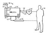
まず、図1を参照すると、本原理に従って、例えば患者16の発熱を予防する、又は患者16に治療的な低体温を誘発するなど、患者の体温を制御するために、システム10が、制御システム14に制御される血管内の熱交換カテーテル12を含んでもよい。カテーテルでは、限定されないが、例えば生理食塩水のような、作動流体又は冷却剤が、(通常は制御システムにおけるポンプ「P」の影響で)制御システム14から、流体供給ラインL1を通り、次にカテーテル12を通り、それから流体リターンラインL2を通りシステム14に戻る閉ループ内で循環し、それにより、いかなる作動流体、又は冷却剤も体内に入ることはない。特定の好適なカテーテルが、本明細書に開示されているが、他のカテーテルが本原理に従って使用されてもよく、これらは、すべてが参照により本明細書に組み込まれる、上記の又は以下の米国特許に開示されている、カテーテルのいずれかを(それらに限定することなく)含むことが理解される。米国特許第6,419,643号、第6,416,533号、第6,409,747号、第6,405,080号、第6,393,320号、第6,368,304号、第6,338,727号、第6,299,599号、第6,290,717号、第6,287,326号、第6,165,207号、第6,149,670号、第6,146,411号、第6,126,684号、第6,306,161号、第6,264,679号、第6,231,594号、第6,149,676号、第6,149,673号、第6,110,168号、第5,989,238号、第5,879,329号、第5,837,003号、第6,383,210号、第6,379,378号、第6,364,899号、第6,325,818号、第6,312,452号、第6,261,312号、第6,254,626号、第6,251,130号、第6,251,129号、第6,245,095号、第6,238,428号、第6,235,048号、第6,231,595号、第6,224,624号、第6,149,677号、第6,096,068号、第6,042,559号、第8,888,729号、第5,486,208号、第5,837,003号、第6,110,168号、第6,149,673号、第6,149,676号、第6,231,594号、第6,264,679号、第6,306,161号、第6,235,048号、第6,238,428号、第6,245,095号、第6,251,129号、第6,409,747号、第6,368,304号、第6,338,727号、第6,299,599号、第6,287,326号、第6,126,684号、第7,211,106号、及び米国特許公開第2013/0178923号、第2013/0079855号、第2013/0079856号、第2014/0094880号、第2014/0094882号、第2014/0094883号。これらすべては、参照により本明細書に組み込まれる。カテーテル12は、例えば、上大静脈又は下大静脈などの静脈系に配置され得る。 First, referring to FIG. 1, according to this principle, the system 10 controls the patient's body temperature in order to control the patient's body temperature, for example, to prevent fever in the patient 16 or to induce a therapeutic hypothermia in the
カテーテル12の代わりに、又はそれに加えて、システム10は1又は複数のパッド18を有してもよく、パッド18は、患者16の外皮に接触するように配置される(明確性のために、1つのパッド18のみを示す)。パッド18は、限定されないが、外部パッド特許で開示されているパッドのいずれか1つであってよい。パッド18の温度は、例えば、心停止、心筋梗塞、脳卒中、高頭蓋内圧、外傷性脳損傷、又は低体温により、症状の改善が得られ得る他の疾患などを患者が示すことに対応して、患者に軽度又は中度の治療的な低体温を誘発することも含めて、患者16と熱交換を行うために、制御システム14により制御され得る。パッド18は、流体供給ラインL3を通り、システム14から作動流体を受け取り得、流体リターンラインL4を通り、システム14に作動流体を戻し得る。ポンプ「P」は、通常は、プラスチック、又は他の材料の点滴ラインである、ラインL1からL4のいずれか1つを係合し得る蠕動ポンプであってよく、作動流体を蠕動によりラインを通り付勢し得る。 Instead of or in addition to the
制御システム14は、1又は複数のマイクロプロセッサ20を有してよく、マイクロプロセッサ20は、入力として目標体温と患者の体温を受け取り、とりわけ、ポンプ「P」と、冷媒コンプレッサ22、及び/又は冷媒にコンデンサをバイパスすることを可能にするために開かれ得るバイパスバルブ24を制御し得る。 The
ここで、図2を参照すると、図1のポンプ「P」の一例が示され、概して、30と指定されている。図2で示されているポンプアセンブリは、冷却プレート31(図2で概略的に示されている)に結合されており、その間に、以下で記載されている熱交換バッグ、又はカセットバッグが、カテーテル12に、及びカテーテル12から、又はパッド18に、及びパッド18から、バッグ内を流れる作動流体と熱交換を行うように配置されることが理解されるだろう。カセットバッグと冷却プレートとの間の相互作用の例示的な詳細は、2014年2月14日に出願され、参照により本明細書に組み込まれる、米国特許出願番号第14/180719号に開示されている。 Here, with reference to FIG. 2, an example of the pump “P” of FIG. 1 is shown, which is generally designated as 30. The pump assembly shown in FIG. 2 is coupled to a cooling plate 31 (schematically shown in FIG. 2), in which the heat exchange bag, or cassette bag, described below, is located. It will be appreciated that the
ポンプ30は、リジッドな、好ましくは金属もしくはハードプラスチックのレースウェイ又はチャンネル筐体32と、ロータ34とを有する。レースウェイ筐体32は、示されているような材料の1又は複数のブロックで形成され得、実質的に一定の曲率半径を有し得る内側の弧状面36を有する。いくつかの例において、弧状面36は、その2つの端部の間に中点38を定め、少なくとも180度の円弧を経て延在することができ、180度から270度の間の円弧を経て延在してもよい。示されている例において、弧状面36は、200度より大きい円弧を経て、一端から他端に延在する。例えば、円弧は約210度から230度であり得る。 The
モータ40が、レースウェイ32に対してロータ34を相対的に回転する。同様に、ロータ34は、ポンプ位置(そこで、ロータ34は、レースウェイ32の内側の表面36の中点38から、第1距離、離間している)とチューブローディング位置(そこで、ロータ34は、中点38から、より長い第2距離、離間している)の間で矢印42で示されているように、レースウェイ32に対して、並進的に可動である。ポンプ位置、又は動作位置において、ロータ34のローラは、ローラとレースウェイ32の間に配置される、点滴チューブのようなチューブに対して付勢する。チューブローディング位置において、チューブ44がレースウェイとロータの間に配置可能となり、及び、例えば、手で、そこから取り外すことができるように、ロータ34は、レースウェイ32から、十分に離間される。ロータ34は、例えば、アクチュエータステッパモータ、手動により作動されるレバーリンケージ、又は他の適切な機構もしくは手段によって、並進的に動かされ得る。 The
1又は複数のローラは、ロータ34に搭載され、チューブ44を通り流体を送り込むそのチューブに対して付勢する。図2に示されている例において、ロータ34は、直線的な非正方形の本体によって部分的に定められ、本体の各角上、又はその近くにおいて、ローラが、例えば、回転可能にロータ本体に搭載されるように、搭載されている。例では、本体上で対向する一対の角に、駆動ローラ46が、それぞれ搭載されており(図2に関しては、1つの駆動ローラのみが示されている)、それに対して、本体上で対向する他の一対の角に、ガイドローラ48が、それぞれ搭載されている。それにより、ガイドローラ48は、駆動ローラ46の間にある。 One or more rollers are mounted on the
図2で示されているように、駆動ローラ46は、円柱外面を有し、外面の少なくとも一部は、チューブ44に対して付勢するように構成されている。例示されている駆動ローラの外面は、単一の滑らかシリンダであってもよく、及び/又は、円柱外面を超えて延在する外縁を有する、1又は複数のフランジを有してもよく、有さなくてもよい。その一方で、ガイドローラ48は、円柱外面も有するが、さらに、ガイドローラの円柱外面を超えて延在する各外縁を定める、頂部フリンジ及び/又は底部フランジを有し、それにより、ロータ34がポンプ位置にあり、回転されるとき、チューブ44は、フランジの間のガイドローラの円柱外面上で受け取られ得る。示されている例において、2つのみの駆動ローラ46、及び、2つのみのガイドローラ48が設けられるが、任意の数の駆動ローラ、及び/又はガイドローラが利用され得る。特定の実施形態において、駆動ローラ、又はガイドローラは、非円柱外面、又は部分的に円柱外面を有してよい。 As shown in FIG. 2, the
チューブ44は、ループとして構成され得、ループの端部は、概して、52と指定される、作動流体カセットのプレナム50と係合される。(下記の実施形態は、プレナムについて言及するが、筐体、コンパートメント、又は他の同様のコンポーネントも利用され得る。)プレナム50は、フレームで囲まれたカセットバッグ54とヒンジ式に係合又は結合される。フレームで囲まれたバッグ54の例示的な詳細は、以下でさらに論じられる。作動流体カセット52と共に使用され得る追加の例示的な詳細は、2014年2月24日に出願され、参照により本明細書に組み込まれる、米国特許出願第14/180613号及び第14/180655号に示され、記載される。そのようなカセットが、制御システム14における構造と係合され得、カセット52及びチューブ44内を流れ、カテーテル12及び/又はパッド18のような熱交換部材に、及びそれらから、例えば、図1に示されているL1及びL2のようなラインを通り、本明細書に示され、記載されているポンプ30により循環される作動流体と熱交換を行う。プレナム50は、点滴バッグ57のような外部の作動流体貯蔵器に、点滴ラインを介して接続されてもよいことを留意されたい。 The
上記で参照されている米国特許出願番号第14/180719号に記載されているように、バッグ54は、冷却プレート31の間に垂直に配置されるとき、下記でさらに記載されているように、ポンプ30のロータがポンプ位置、又は動作位置に動く場合、プレナム50は所定の位置に固定され得る。 As described in US Patent Application No. 14/180719 referenced above, when the
例において、カセットバッグ54は、互いに接近して離間される2つの高分子膜で作られてよく、図2のポンプを支持する冷却プレートアセンブリのスロット56と摺動可能に係合するフレームにより支持されてよい。作動流体チャンバが、それらの膜の間に設けられる。一例において、各膜の厚みは、2ミル(0.002インチ(50.8マイクロメートル))より薄く、より好ましくは、2つの膜を含めて1ミルから2ミル(0.001から0.002インチ(25.4から50.8マイクロメートル))の間である。例示されている好適な膜は、事実上、正方形であり、例示されている膜の頂部と底部の縁部の長さが、膜の左側と右側の縁部の長さとほぼ同等(±10%以内、及びより好ましくは±5%以内)である。ゆえに、膜の間の作動流体チャンバは、直線であり得、膜の間に何の障害物も存在し得ず、つまり、作動流体チャンバは、完全な直線で、事実上、正方形のチャンバである。好適な例において、膜は、フレームに取り付ける組み立ての間、張力により引っ張られる。 In an example, the
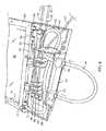
図3及び図4において示されているように、カセットバッグ54は、フレーム60により囲まれており、プレナム50は、プレナム50の開かれた底面64がフレーム60に平行であり、バッグ54から接近して離間される輸送位置(図3)と、開かれた底面64が、輸送位置から90度回転され、それにより、フレーム60に対して垂直である、又は垂直に近い動作位置(図4)との間での移動のために、ヒンジ62でフレーム60と接合される。ヒンジ付きプレナム又は筐体50は、複数の長所と利点とを提供する。例えば、カセットによりコンパクトな輸送構成、又は動作位置を容易に想定させることができる。カセットが冷却プレート内に位置し、ポンプへ結合されるとき、フレームに対して垂直、又は角度がついたプレナム又は筐体の配置は、カセット及びポンプの間で角度公差の増加をもたらす。また、垂直又は角度がついた構成により、カセットが、冷却プレートの間に位置し、チューブ44がポンプと結合されているとき、ユーザが、ポンプと冷却プレートを上から同時に確認することができる。プレナム又は筐体の底面64は、開かれた構成を有するように示されているが、特定の実施形態において、底面は、底面は閉じられてもよく、又は、底面の少なくとも一部は閉じられてもよい。底面64は、示されているように、概して、長方形で、フレーム60の幅に延在する。いくつかの例において、図5で示されているように、プレナム50又は筐体は、フレーム60に対して、鈍角を成立させるために、動作位置を超えて旋回、又は回転され得る。図3に最も良く示されているように、底面64は、相補的な形状の、閉じられた、又は開かれた頂面66により対向されており、そこから、側壁68により離間される。 As shown in FIGS. 3 and 4, the
図6は、プレナム50の開かれた底面64の内部を示している。カテーテル12、又は熱交換パッド18から作動流体を運搬するリターンチューブ70が、プレナム50の側壁68の1つに入る。リターンチューブ70は、反対側に向かって、プレナム50を横切り、そこで、サポート、又はベアリング72により支持され、トップレール76の導入開口部74に入る。リターンチューブ70は、図11を参照して以下にさらに論じられているように、バッグ54のトップレール76の真下で終わる。作動流体は、矢印78で示されているように、リターンチューブからバッグ54に流れ込み、バッグの中を横断して戻り、トップレール76の開口部を通り延在する出口チューブ80から流れ出る。 FIG. 6 shows the inside of the
次に、出口チューブ80は、例えば、入口ポートコネクタ86を通り、プレナム50内の、周囲を囲まれた作動流体貯蔵器84に入る。貯蔵器は、筐体又はプレナム内に位置する、別個の容器もしくはマニホールドであってよく、又は筐体もしくはプレナムと一体であってもよい。貯蔵器は、システムの運用に必要な、又は要求される量の作動流体を集める、又は保持し得る。貯蔵器の流体レベルが閾値を下回るとき、信号を発生させるための、1又は複数レベルのセンサが、貯蔵器84に設けられてもよい。信号は、警告ランプ、又はアラーム音を有効にするために用いられ得る。入口ポートコネクタ86は、示されている底部の図において、貯蔵器84の最上部近くに設置されることに留意されたい。また、点滴バッグライン、又はチューブ87は、点滴バッグコネクタ88を介して貯蔵器84に接続され、図2で示されているように、作動流体を点滴バッグ57からシステムに供給する。実施形態は、点滴バッグについて言及するが、他の点滴又は作動流体源は、例えば、ボトル、バッグ又は他の容器などを使用し得る。貯蔵器84は、例えば、システムのプライミング中に、貯蔵器84に作動流体を配送する、及び/又は、作動流体の量の温度及び他の変動を補正するために用いられる単一ライン87を通り点滴バッグに接続され得る。ライン87は、空気をシステムから、点滴バッグに排出し、及び/又は、処理の終わりで、システムのパージ、又は排液中に作動流体を点滴バッグに戻すためにも使用され得る。 The
閉流体回路パスにおける、単一ライン、又はチューブ87は、作動流体に対して、無菌バリヤ又は無菌環境を提供し、利便性の向上又は改善も提供する。所望される場合、例えば、プライミング中に、例えば、生理食塩水などの作動流体は、ライン87を通り配送され得、空気は、同じライン87を通り逆向きの方向に戻り得、2つの異なる流体を同じラインを通り配送することができる。生理食塩水及び空気の配送は、同時に起こらなくてもよく、及び/又は、フィルタが必ずしも必要というわけでもない。フィルタを有さない単一点滴バッグラインを利用する、閉流体回路パス、又は閉ループシステムは、最大7日まで動作することができ、特定の実施形態において、7日よりも長く動作することができる。本明細書に記載されているポンプは、両方向に動作可能であり、ポンプは、自己プライミングすることができ、そのため、乾燥している場合ですら、空気及び/又は水を送り込み、動作することができる。 A single line, or tube 87, in a closed fluid circuit path provides a sterile barrier or sterile environment for the working fluid and also provides an improvement or improvement in convenience. If desired, for example, during priming, working fluids such as saline can be delivered through line 87 and air can return in opposite directions through the same line 87 and two different fluids. Can be delivered through the same line. Saline and air delivery do not have to occur at the same time and / or filters are not always required. A closed fluid circuit path, or closed loop system, utilizing a single drip bag line without a filter can operate for up to 7 days and, in certain embodiments, longer than 7 days. .. The pumps described herein can operate in both directions, and the pumps can be self-priming, so that they can pump and operate air and / or water even when dry. it can.
貯蔵器84の底部近くで、排出コネクタ90は、貯蔵器84内の作動流体とチューブ出口開口部92を通り延在する蠕動チューブ44との間で、上記の蠕動ポンプを係合するために流体連通を成立させる。ポンプは、本明細書に記載されている経路で作動流体を循環するために、チューブ44に対して付勢する。チューブ44は、減衰器チューブ96と係合する、又は一体形成されるチューブ入口開口部94を通り、プレナム50に再び入る。チューブ44は、下流減衰器、もしくは減衰器チューブに直接、又は中間チューブもしくはマニホールド介して接続され得る。 Near the bottom of the
示されているように、例示される減衰器チューブ96は、出口チューブ80より大きい直径を有し、さらに、例えば、示されているように、1又は複数の180度のループを通り屈曲されながら、プレナム50の中を横断するように、1又は複数、又は多数回往復して延在する。代わりに、減衰器チューブは、部分的に、又は全体的に、プレナムの外側に設置され得る。減衰器チューブ96の目的は、蠕動送り込み動作により引き起こされる作動流体のパルスを減衰することである。減衰器チューブ96は、クランプのような接合部100で、より小さい直径を有する作動流体供給チューブ98に接合される。作動流体は、供給チューブ98を通り、カテーテル12又はパッド18に運ばれる。 As shown, the illustrated
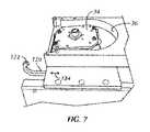
図7から図10は、ポンプ30とカセット52の間に提供され得る、例示的な連結を示す。図7及び図9は、ローディング構成又はローディング位置におけるロータ34を有するポンプアセンブリを示し、図8及び図10は、ロック(動作又はポンプ)構成又は位置におけるロータ34を有するポンプアセンブリを示す。 7 to 10 show exemplary connections that may be provided between the
図7及び図9において、上方向に突出する係合フック122で終わる水平ロッキングバー120が、ロータ34を支持する、ロータキャリッジ、又はモータマウントに接続され、それにより、ロッキングバー120は、図2を参照して記載されているように、ロータキャリッジ又はマウント及びロータが動くとき、矢印124によって示される方向に動く。ロータキャリッジ又はマウント(従って、ロッキングバー120)は、図7及び図9におけるローディング位置にあり、そこで、ロータ34は、レースウェイ又はレースウェイ面36から離間され、カセット52のポンプチューブ44は、ロータ34とレースウェイの間で係合され、その間の空間に配置されることが可能となる。図9で示されているように、係合棚126、又はカセット52の底部の突出は、この位置において、係合フック122から離れており、カセット52は、レースウェイ32にポンプチューブ44を配置するように動かされることが可能となる。 In FIGS. 7 and 9, a
その一方で、図8及び図10では、ポンプローラが、レースウェイ又はレースウェイ面36に対してポンプチューブ44を付勢し得るように、ロータキャリッジ又はマウント及びロータ34が、ロック位置、ポンプ位置、動作位置に動かされるとき、ロッキングバー120もまた、係合フック122が、係合棚126の上部面上に動いた位置に動き、係合棚126を、従って、カセット52を捕捉し、それにより、ロータキャリッジ又はマウント、ロータ、及び、フック122を有するロッキングバー120が、ロック位置、ポンプ位置、動作位置にあるとき、カセット52は引き戻されることがないことが示されている。 On the other hand, in FIGS. 8 and 10, the rotor carriage or mount and the
図11で示されているように、いくつかの例において、図6のリターンチューブ70からの作動流体は、プレナム50又は筐体(図11には不図示)を通過し、入口チューブ130(リターンチューブと同じものであってもよく、又はリターンチューブに接続されてもよい)に進む。入口チューブ130は、カセットフレーム60のトップレール134における開口部132に進み、バッグ54に入る。示されている例において、入口チューブ130は、トップレール134で、又はちょうどトップレール134の下(例えば、4分の1インチ(0.635センチメートル)下)で終わり、それにより、作動流体は、トップレール134近傍の入口チューブ130から流れ出て、下向きに流れ、バッグ54の中を横断して流れる。 As shown in FIG. 11, in some examples, the working fluid from the return tube 70 of FIG. 6 passes through the
入口チューブ130より小さい直径を有する排液チューブ138は、示されているように、トップレール134の向かい側にあり、トップレール134に平行である、フレーム60のボトムレール140に向かって、入口チューブ130を通り延在する。排液チューブ138は、ボトムレール140近傍(例えば、ボトムレール140の4分の1インチ(0.635センチメートル)程度以内)の開口部142で終わる。作動流体は、患者の体温管理動作中、カテーテル12とバッグ54を通り循環され、カテーテル12からカセット52に返還される、作動流体の少なくとも一部は、カセット52の頂部近くで、入口チューブ130のより大きい直径を有する開口部から出て、作動流体の少なくとも一部は、バッグ54に流れ落ち、その中を横断して流れ、バッグ54がその間に配置されるプレートと熱交換を行う。 The
バッグ54に作動流体がいっぱいに満たされたままの状態であるときに、プレートからバッグ54を取り出すことが妨げられる可能性があり、プレートからバッグを取り出すことを容易するために、カテーテル、及び/又はバッグから排液することが所望されるとき、ポンプは逆回転され得る。これは、排液チューブ138を通り、バッグ54から、作動流体を排出する。排出によって、より大きな入口チューブ130の周りで、バッグの材料がつぶれた状態になり、排液チューブ138の開口部142で、吸引の大部分はそのままになる。作動流体は、排液チューブ138を通り、プレナム又は筐体の貯蔵器84に送り戻され、そこから点滴バッグに送り込まれる。カテーテルは、カセット52に接続されたままであるとき、作動流体もカテーテルから排出される。カテーテルは、バッグ54から排液する前に接続されていないとき、カテーテル点滴ラインをカセットの供給ライン及びリターンラインに接続するコネクタ(通常はルアーフィッティング)は、単に流体ループの近くにともに接続されてもよい。 Removing the
特定の実施形態において、チェックバルブ81(図6)が、熱交換バッグ54と貯蔵器84の間のライン、またはチューブ上、又はそれらの中に配置され得、流体の排出、又はパージ中、作動流体が、貯蔵器84から熱交換バッグ54に戻ることを防ぐ。必要に応じて、チェックバルブ81は、貯蔵器84内部に配置されてもよく、流体の排出、又はパージ中、作動流体が、貯蔵器84から熱交換バッグ54に戻るのを防ぐ。そのようなバルブは、熱交換バッグは適切に排液され得、熱交換プレートの間から容易に取り外され得るように、作動流体が排出され、及び/又は点滴バッグもしくは他の容器に流れ戻ることを確実にし得る。カテーテルがシステムに接続されているとき、作動流体は、カテーテルから排出されてよく、又は排液されてもよく、それにより、カテーテルが患者から取り除かれ得るように、カテーテルの直径を小さくする。熱交換バッグのみから、作動流体が排液され、又は排出されるように、所望されるならば、カテーテルの接続が外されてもよい。他の実施形態において、作動流体のパージ又は排液が、チェックバルブの有無に関わらず実行され得るように、作動流体の量を変動させる高圧減衰器が利用されてもよい。 In certain embodiments, the check valve 81 (FIG. 6) can be placed on or in the line or tube between the
特定の実施形態において、プライミング中に、カセットバッグが満たされるとき、空気をプレナム又は筐体内の貯蔵器を通り戻すことが可能となるように、ポンプは、短期間で開始されたり、停止されたりできる。ポンプは、貯蔵器を通り、及び/又は点滴バッグもしくは流体源に、空気を戻す動きを加速するため、逆回転され得ることもある。単一ラインが、フィルタを使用することなく、貯蔵器と点滴バッグ又は流体源の間で、液体及び/又は空気を配送するために用いられ得る。 In certain embodiments, the pump is started or stopped in a short period of time so that during priming, when the cassette bag is filled, air can be passed back through the plenum or the reservoir inside the enclosure. it can. The pump may also be reversed to accelerate the movement of air back through the reservoir and / or to the IV bag or fluid source. A single line can be used to deliver liquids and / or air between the reservoir and the drip bag or fluid source without the use of filters.
一実施形態に含まれるコンポーネントは、任意の適切な組み合わせで、他の実施形態において用いられ得る。例えば、本明細書に記載されている、及び/又は図示されている様々なコンポーネントのいずれかが、組み合わされてもよく、置き換えられてもよく、他の実施形態から除外されてもよい。「A、B、及びCの少なくとも1つを有するシステム」(同様に、「A、B、又はCの少なくとも1つを有するシステム」及び「A、B、Cの少なくとも1つを有するシステム」)は、Aを単独で、Bを単独で、Cを単独で有するシステム、AとBをともに、AとCをともに、BとCをともに有するシステム、及び/又は、AとBとCとをともに有するシステムなどを含む。 The components included in one embodiment may be used in other embodiments in any suitable combination. For example, any of the various components described and / or illustrated herein may be combined, replaced, or excluded from other embodiments. "System with at least one of A, B, and C" (similarly, "system with at least one of A, B, or C" and "system with at least one of A, B, C") A system with A alone, B alone, C alone, A and B together, A and C together, B and C together, and / or A, B, and C. Includes systems that have both.
血管内の温度管理カテーテルと熱交換器を接続するためのヒンジ付きプレナム又は筐体を有する作動流体カセットの様々な実施形態が、本明細書において示され、詳細に記載されるが、本発明の範囲は、添付の請求項によってのみ限定される。 Various embodiments of working fluid cassettes with hinged plenums or enclosures for connecting intravascular temperature control catheters and heat exchangers are set forth herein and described in detail, according to the present invention. The scope is limited only by the attached claims.
Claims (7)
Translated fromJapanese前記筐体と接続されるフレームで囲まれた熱交換バッグであって、前記熱交換バッグは、血管内の熱交換カテーテル、又は外部熱交換パッドからの作動流体を保持し、前記フレームで囲まれた熱交換バッグは、対向するプレートと前記熱交換バッグ内を流れる作動流体との間で熱交換をもたらすために、前記対向するプレートの間の挿入物のように構成され、前記フレームで囲まれた熱交換バッグが、前記プレートの間にあるとき、前記筐体からの前記ポンプチューブは、ポンプのレースウェイで受けられる、熱交換バッグと
を備え、
前記筐体の開かれた底面が、前記フレームに平行であり、前記熱交換バッグから接近して離間される輸送位置と、前記開かれた底面が、前記フレームに対して垂直である動作位置との間での移動のために、前記筐体は、前記フレームで囲まれた熱交換バッグのフレームにヒンジ式に接続される、デバイス。The housing that supports the pump tube and
A heat exchange bag surrounded by a frame connected to the housing, wherein the heat exchange bag holds working fluid from an intravascular heat exchange catheter or an external heat exchange pad and is surrounded by the frame. The heat exchange bag is configured like an insert between the opposing plates to provide heat exchange between the opposing plates and the working fluid flowing through the heat exchange bag and is surrounded by the frame. heat exchanger bag when located between the plates, the pump tube from the housing is received in the raceway of the pump,e Bei a heat exchangerbag,
A transport position in which the open bottom surface of the housing is parallel to the frame and is approached and separated from the heat exchange bag, and an operating position in which the open bottom surface is perpendicular to the frame. A device in which the housing is hinged to the frame of a heat exchange bag surrounded by the frame for movement between .
Priority Applications (1)
| Application Number | Priority Date | Filing Date | Title |
|---|---|---|---|
| JP2021068866AJP7251894B2 (en) | 2015-04-01 | 2021-04-15 | device |
Applications Claiming Priority (3)
| Application Number | Priority Date | Filing Date | Title |
|---|---|---|---|
| US14/676,672 | 2015-04-01 | ||
| US14/676,672US10022265B2 (en) | 2015-04-01 | 2015-04-01 | Working fluid cassette with hinged plenum or enclosure for interfacing heat exchanger with intravascular temperature management catheter |
| PCT/US2016/025030WO2016161002A1 (en) | 2015-04-01 | 2016-03-30 | Working fluid cassette with hinged plenum or enclosure for interfacing heat exchanger with intravascular temperature management catheter |
Related Child Applications (1)
| Application Number | Title | Priority Date | Filing Date |
|---|---|---|---|
| JP2021068866ADivisionJP7251894B2 (en) | 2015-04-01 | 2021-04-15 | device |
Publications (2)
| Publication Number | Publication Date |
|---|---|
| JP2018509992A JP2018509992A (en) | 2018-04-12 |
| JP6872298B2true JP6872298B2 (en) | 2021-05-19 |
Family
ID=57006404
Family Applications (2)
| Application Number | Title | Priority Date | Filing Date |
|---|---|---|---|
| JP2017549752AActiveJP6872298B2 (en) | 2015-04-01 | 2016-03-30 | device |
| JP2021068866AActiveJP7251894B2 (en) | 2015-04-01 | 2021-04-15 | device |
Family Applications After (1)
| Application Number | Title | Priority Date | Filing Date |
|---|---|---|---|
| JP2021068866AActiveJP7251894B2 (en) | 2015-04-01 | 2021-04-15 | device |
Country Status (7)
| Country | Link |
|---|---|
| US (2) | US10022265B2 (en) |
| EP (2) | EP3912604A1 (en) |
| JP (2) | JP6872298B2 (en) |
| CN (2) | CN113855379A (en) |
| AU (1) | AU2016242860A1 (en) |
| CA (1) | CA2980925A1 (en) |
| WO (1) | WO2016161002A1 (en) |
Families Citing this family (12)
| Publication number | Priority date | Publication date | Assignee | Title |
|---|---|---|---|---|
| US9474644B2 (en) | 2014-02-07 | 2016-10-25 | Zoll Circulation, Inc. | Heat exchange system for patient temperature control with multiple coolant chambers for multiple heat exchange modalities |
| US11033424B2 (en) | 2014-02-14 | 2021-06-15 | Zoll Circulation, Inc. | Fluid cassette with tensioned polymeric membranes for patient heat exchange system |
| US10500088B2 (en) | 2014-02-14 | 2019-12-10 | Zoll Circulation, Inc. | Patient heat exchange system with two and only two fluid loops |
| US10792185B2 (en) | 2014-02-14 | 2020-10-06 | Zoll Circulation, Inc. | Fluid cassette with polymeric membranes and integral inlet and outlet tubes for patient heat exchange system |
| US11359620B2 (en) | 2015-04-01 | 2022-06-14 | Zoll Circulation, Inc. | Heat exchange system for patient temperature control with easy loading high performance peristaltic pump |
| US9784263B2 (en) | 2014-11-06 | 2017-10-10 | Zoll Circulation, Inc. | Heat exchange system for patient temperature control with easy loading high performance peristaltic pump |
| US10537465B2 (en) | 2015-03-31 | 2020-01-21 | Zoll Circulation, Inc. | Cold plate design in heat exchanger for intravascular temperature management catheter and/or heat exchange pad |
| US10022265B2 (en) | 2015-04-01 | 2018-07-17 | Zoll Circulation, Inc. | Working fluid cassette with hinged plenum or enclosure for interfacing heat exchanger with intravascular temperature management catheter |
| US10588778B2 (en)* | 2016-03-21 | 2020-03-17 | Stryker Corporation | Mobile thermal system |
| US11337851B2 (en) | 2017-02-02 | 2022-05-24 | Zoll Circulation, Inc. | Devices, systems and methods for endovascular temperature control |
| US11116657B2 (en) | 2017-02-02 | 2021-09-14 | Zoll Circulation, Inc. | Devices, systems and methods for endovascular temperature control |
| US11185440B2 (en) | 2017-02-02 | 2021-11-30 | Zoll Circulation, Inc. | Devices, systems and methods for endovascular temperature control |
Family Cites Families (279)
| Publication number | Priority date | Publication date | Assignee | Title |
|---|---|---|---|---|
| US1459112A (en) | 1922-02-23 | 1923-06-19 | Charles F Mehl | Invalid bed |
| US1726761A (en) | 1926-12-15 | 1929-09-03 | Stephen L Palmer | Hot-water bottle |
| US1857031A (en) | 1929-08-02 | 1932-05-03 | Schaffer Edward | Combined hoist and conveyer |
| GB659339A (en) | 1948-04-26 | 1951-10-24 | Bengt Rudolf Dahlberg | Improvements in apparatus for lifting, temporarily supporting and transferring persons in a reclining position |
| US2673987A (en) | 1951-10-22 | 1954-04-06 | James L Upshaw | Invalid carrier with rotatable chair |
| US2987004A (en) | 1955-07-29 | 1961-06-06 | Jerome L Murray | Fluid pressure device |
| FR1467878A (en) | 1960-11-21 | 1967-02-03 | Cigarette lighter-distributor device intended for motor vehicle equipment | |
| US3140716A (en) | 1961-06-26 | 1964-07-14 | Baxter Laboratories Inc | Heat exchanger for blood |
| US3225191A (en) | 1962-06-01 | 1965-12-21 | Industrial Dynamics Co | Infrared liquid level inspection system |
| US3425419A (en) | 1964-08-08 | 1969-02-04 | Angelo Actis Dato | Method of lowering and raising the temperature of the human body |
| US3369549A (en) | 1965-10-05 | 1968-02-20 | Thomas A. Armao | Capsule probe having thermoelectric heat exchange means therein |
| US3504674A (en) | 1966-12-22 | 1970-04-07 | Emil S Swenson | Method and apparatus for performing hypothermia |
| GB1183185A (en) | 1967-03-06 | 1970-03-04 | Sp K B Poluprovodnikovykh Prib | Apparatus for Controlling the Temperature of a Living Body |
| US3744555A (en) | 1971-11-12 | 1973-07-10 | Gen Electric | Automatic control of liquid cooling garment by cutaneous and external auditory meatus temperatures |
| US3726269A (en) | 1971-11-24 | 1973-04-10 | W Webster | Cardiovascular catheter for thermal dilution measurement |
| US3751077A (en) | 1972-02-28 | 1973-08-07 | Imp Eastman Corp | Welded sleeve fitting |
| NL7414546A (en) | 1973-11-15 | 1975-05-20 | Rhone Poulenc Sa | SMOOTH HEATING TUBE AND PROCESS FOR MANUFACTURING IT. |
| JPS5247636B2 (en) | 1973-12-15 | 1977-12-03 | ||
| US3937224A (en) | 1974-04-11 | 1976-02-10 | Uecker Ronald L | Colostomy catheter |
| US4126132A (en) | 1975-07-28 | 1978-11-21 | Andros Incorporated | Intravenous and intra arterial delivery system |
| US4065264A (en) | 1976-05-10 | 1977-12-27 | Shiley Laboratories, Inc. | Blood oxygenator with integral heat exchanger for regulating the temperature of blood in an extracorporeal circuit |
| US4103511A (en) | 1976-10-04 | 1978-08-01 | Firma Kress Elektrik Gmbh & Co. | Connecting arrangement for a machine tool |
| US4173228A (en) | 1977-05-16 | 1979-11-06 | Applied Medical Devices | Catheter locating device |
| US4181132A (en) | 1977-05-31 | 1980-01-01 | Parks Leon C | Method and apparatus for effecting hyperthermic treatment |
| US4153048A (en) | 1977-09-14 | 1979-05-08 | Cleveland Clinic Foundation | Thermodilution catheter and method |
| US4181245A (en) | 1978-02-17 | 1980-01-01 | Baxter Travenol Laboratories, Inc. | Casette for use with an I.V. infusion controller |
| US4259961A (en) | 1979-01-24 | 1981-04-07 | Hood Iii Andrew G | Cooling pad |
| US4298006A (en) | 1980-04-30 | 1981-11-03 | Research Against Cancer, Inc. | Systemic hyperthermia with improved temperature sensing apparatus and method |
| US4532414A (en) | 1980-05-12 | 1985-07-30 | Data Chem., Inc. | Controlled temperature blood warming apparatus |
| US4731072A (en) | 1981-05-11 | 1988-03-15 | Mcneilab, Inc. | Apparatus for heating or cooling fluids |
| US4459468A (en) | 1982-04-14 | 1984-07-10 | Bailey David F | Temperature control fluid circulating system |
| US5370675A (en) | 1992-08-12 | 1994-12-06 | Vidamed, Inc. | Medical probe device and method |
| US4581017B1 (en) | 1983-03-07 | 1994-05-17 | Bard Inc C R | Catheter systems |
| US4554793A (en) | 1983-06-09 | 1985-11-26 | General Eastern Instruments Corporation | Controlled power converter for thermoelectric heat pump drive |
| US4558996A (en) | 1983-06-30 | 1985-12-17 | Organon Teknika Corporation | Easy load peristaltic pump |
| JPS6028085A (en) | 1983-07-25 | 1985-02-13 | Canon Inc | Head drive device in recording or playback equipment |
| US4672962A (en) | 1983-09-28 | 1987-06-16 | Cordis Corporation | Plaque softening method |
| US4552516A (en) | 1984-06-15 | 1985-11-12 | Cole-Parmer Instrument Company | Peristaltic pump |
| US4653987A (en) | 1984-07-06 | 1987-03-31 | Tsuyoshi Tsuji | Finger peristaltic infusion pump |
| US4638436A (en) | 1984-09-24 | 1987-01-20 | Labthermics Technologies, Inc. | Temperature control and analysis system for hyperthermia treatment |
| JPS61100243A (en) | 1984-10-23 | 1986-05-19 | 工業技術院長 | Apparatus for automatically controlling bodily temperature |
| US4661094A (en) | 1985-05-03 | 1987-04-28 | Advanced Cardiovascular Systems | Perfusion catheter and method |
| SE8504501D0 (en) | 1985-09-30 | 1985-09-30 | Astra Meditec Ab | METHOD OF FORMING AN IMPROVED HYDROPHILIC COATING ON A POLYMER SURFACE |
| CH668192A5 (en) | 1985-11-29 | 1988-12-15 | Schneider Medintag Ag | CATHETER FOR TREATING NARROW BODIES, FOR EXAMPLE IN A BLOOD VESSEL. |
| US4707587A (en) | 1986-01-27 | 1987-11-17 | Greenblatt Gordon M | Blood warming method and apparatus using gaseous heat exchange medium |
| US4665391A (en) | 1986-02-27 | 1987-05-12 | Warner-Lambert Company | Empty container detector |
| US4754752A (en) | 1986-07-28 | 1988-07-05 | Robert Ginsburg | Vascular catheter |
| JPS63159300A (en) | 1986-12-23 | 1988-07-02 | Shin Etsu Chem Co Ltd | Method for producing silicon carbide whiskers |
| US4842584A (en)* | 1987-05-01 | 1989-06-27 | Abbott Laboratories | Disposable fluid infusion pumping chamber cassette and drive mechanism thereof |
| US4925376A (en) | 1987-06-26 | 1990-05-15 | Tek-Aids, Inc. | Peristaltic pump with tube holding mechanism |
| US4813855A (en) | 1987-06-26 | 1989-03-21 | Tek-Aids Inc. | Peristaltic pump |
| JPS6446056U (en) | 1987-09-17 | 1989-03-22 | ||
| US4860744A (en) | 1987-11-02 | 1989-08-29 | Raj K. Anand | Thermoelectrically controlled heat medical catheter |
| GB2212262B (en) | 1987-11-09 | 1992-07-22 | Solinst Canada Ltd | Liquid level detector |
| US4852567A (en) | 1988-01-21 | 1989-08-01 | C. R. Bard, Inc. | Laser tipped catheter |
| US4941475A (en) | 1988-08-30 | 1990-07-17 | Spectramed, Inc. | Thermodilution by heat exchange |
| JPH03502732A (en) | 1988-10-20 | 1991-06-20 | コナックス バッファロウ コーポレーション | optical level sensor |
| FR2693116B1 (en) | 1992-07-06 | 1995-04-28 | Technomed Int Sa | Urethral probe and apparatus for the therapeutic treatment of prostate tissue by thermotherapy. |
| US5174285A (en) | 1990-01-08 | 1992-12-29 | Lake Shore Medical Development Partners Ltd. | Localized heat transfer device |
| US5342301A (en) | 1992-08-13 | 1994-08-30 | Advanced Polymers Incorporated | Multi-lumen balloons and catheters made therewith |
| US5624392A (en) | 1990-05-11 | 1997-04-29 | Saab; Mark A. | Heat transfer catheters and methods of making and using same |
| US5092841A (en) | 1990-05-17 | 1992-03-03 | Wayne State University | Method for treating an arterial wall injured during angioplasty |
| US5080089A (en) | 1990-09-05 | 1992-01-14 | Breg, Inc. | Therapeutic apparatus applying compression and a nonambient temperature fluid |
| US5507792A (en) | 1990-09-05 | 1996-04-16 | Breg, Inc. | Therapeutic treatment device having a heat transfer element and a pump for circulating a treatment fluid therethrough |
| US5584804A (en) | 1990-10-10 | 1996-12-17 | Life Resuscitation Technologies, Inc. | Brain resuscitation and organ preservation device and method for performing the same |
| US5195965A (en) | 1991-03-07 | 1993-03-23 | Shantha Totada R | Method and apparatus for localized treatment of human viral infections and cancers |
| US5381510A (en) | 1991-03-15 | 1995-01-10 | In-Touch Products Co. | In-line fluid heating apparatus with gradation of heat energy from inlet to outlet |
| JP3091253B2 (en) | 1991-04-25 | 2000-09-25 | オリンパス光学工業株式会社 | Thermal treatment equipment |
| US5192274A (en) | 1991-05-08 | 1993-03-09 | Bierman Steven F | Anchor pad for catheterization system |
| US5263925A (en) | 1991-07-22 | 1993-11-23 | Gilmore Jr Thomas F | Photopheresis blood treatment |
| US5211631A (en) | 1991-07-24 | 1993-05-18 | Sheaff Charles M | Patient warming apparatus |
| GB9118670D0 (en) | 1991-08-30 | 1991-10-16 | Mcnicholas Thomas A | Surgical devices and uses thereof |
| US5304214A (en) | 1992-01-21 | 1994-04-19 | Med Institute, Inc. | Transurethral ablation catheter |
| US6059825A (en) | 1992-03-05 | 2000-05-09 | Angiodynamics, Inc. | Clot filter |
| US5281215A (en) | 1992-04-16 | 1994-01-25 | Implemed, Inc. | Cryogenic catheter |
| US5269758A (en) | 1992-04-29 | 1993-12-14 | Taheri Syde A | Intravascular catheter and method for treatment of hypothermia |
| DE4221390C1 (en) | 1992-06-30 | 1993-04-01 | Haindl, Hans, Dr.Med., 3015 Wennigsen, De | |
| US5403281A (en) | 1992-09-25 | 1995-04-04 | Minnesota Mining And Manufacturing Company | Inline heat exchanger and cardioplegia system |
| US5391030A (en) | 1992-10-14 | 1995-02-21 | Lee; Ray | Wheelchair restraint affixment straps |
| US6325067B1 (en) | 1992-12-03 | 2001-12-04 | Wesley D. Sterman | Methods and systems for performing thoracoscopic coronary bypass and other procedures |
| US5437673A (en) | 1993-02-04 | 1995-08-01 | Cryomedical Sciences, Inc. | Closed circulation tissue warming apparatus and method of using the same in prostate surgery |
| US5486208A (en) | 1993-02-10 | 1996-01-23 | Ginsburg; Robert | Method and apparatus for controlling a patient's body temperature by in situ blood temperature modification |
| US5837003A (en) | 1993-02-10 | 1998-11-17 | Radiant Medical, Inc. | Method and apparatus for controlling a patient's body temperature by in situ blood temperature modification |
| US6620188B1 (en) | 1998-08-24 | 2003-09-16 | Radiant Medical, Inc. | Methods and apparatus for regional and whole body temperature modification |
| US6110168A (en) | 1993-02-10 | 2000-08-29 | Radiant Medical, Inc. | Method and apparatus for controlling a patient's body temperature by in situ blood temperature modifications |
| US5383856A (en) | 1993-03-19 | 1995-01-24 | Bersin; Robert M. | Helical spiral balloon catheter |
| US5626618A (en) | 1993-09-24 | 1997-05-06 | The Ohio State University | Mechanical adjunct to cardiopulmonary resuscitation (CPR), and an electrical adjunct to defibrillation countershock, cardiac pacing, and cardiac monitoring |
| US5433588A (en) | 1993-12-15 | 1995-07-18 | Stryker Corporation | Peristaltic pump with one piece tubing insert and one piece cover |
| US5387088A (en) | 1994-01-18 | 1995-02-07 | Haemonetics Corporation | Peristaltic pump tube loading assembly |
| US6716216B1 (en) | 1998-08-14 | 2004-04-06 | Kyphon Inc. | Systems and methods for treating vertebral bodies |
| US5429184A (en) | 1994-03-28 | 1995-07-04 | Minntech Corporation | Wound heat exchanger oxygenator |
| JP3442863B2 (en) | 1994-06-10 | 2003-09-02 | 隆 松浦 | Patient bed with release frame and moving device for release frame |
| US5716386A (en) | 1994-06-27 | 1998-02-10 | The Ohio State University | Non-invasive aortic impingement and core and cerebral temperature manipulation |
| US5458639A (en) | 1994-08-05 | 1995-10-17 | Medtronic, Inc. | Catheter balloon distal bond |
| EP0698940B1 (en) | 1994-08-24 | 2000-06-14 | Sumitomo Wiring Systems, Ltd. | Wiring circuit for an electrical connection box, method and apparatus for forming the wiring circuit |
| US5486207A (en) | 1994-09-20 | 1996-01-23 | Mahawili; Imad | Thermal pad for portable body heating/cooling system and method of use |
| US5895418A (en) | 1994-09-30 | 1999-04-20 | Saringer Research Inc. | Device for producing cold therapy |
| US5531714A (en) | 1994-11-01 | 1996-07-02 | M. Patricia Lange | Self-guiding, multifunctional visceral catheter |
| US5634907A (en) | 1994-12-22 | 1997-06-03 | Sandoz Nutrition Ltd. | System for detection of fluid infusion |
| US5980561A (en) | 1995-03-01 | 1999-11-09 | Kolen; Paul T. | Applying thermal therapy to living tissue |
| US6149806A (en) | 1995-05-12 | 2000-11-21 | Baer; William | Two piece frame and two piece diaphragm filter plate |
| DE19531935A1 (en) | 1995-08-17 | 1997-02-20 | Panagiotis Tsolkas | Device for whole body hyperthermia treatment |
| US5730720A (en) | 1995-08-18 | 1998-03-24 | Ip Scientific, Inc. | Perfusion hyperthermia treatment system and method |
| US5857843A (en) | 1995-10-20 | 1999-01-12 | Harvest Technologies Llc | Peristaltic pump with removable rotor |
| US5701905A (en) | 1995-11-13 | 1997-12-30 | Localmed, Inc. | Guide catheter with sensing element |
| US5759017A (en) | 1996-01-31 | 1998-06-02 | Medtronic Electromedics, Inc. | Peristaltic pump and tube loading system |
| DE29602173U1 (en) | 1996-02-08 | 1997-06-26 | B. Braun Melsungen Ag, 34212 Melsungen | Application device for medical liquids |
| US5733319A (en) | 1996-04-25 | 1998-03-31 | Urologix, Inc. | Liquid coolant supply system |
| US5676670A (en) | 1996-06-14 | 1997-10-14 | Beth Israel Deaconess Medical Center | Catheter apparatus and method for creating a vascular bypass in-vivo |
| US5776079A (en) | 1996-08-06 | 1998-07-07 | Cook Incorporated | Retrograde-antegrade catheterization guide wire |
| US6146141A (en) | 1996-10-02 | 2000-11-14 | Schumann; Edgar | Laser pistol |
| JPH10127777A (en) | 1996-10-31 | 1998-05-19 | Sumitomo Bakelite Co Ltd | Pharmaceutical liquid injecting port |
| US6124452A (en) | 1997-12-19 | 2000-09-26 | University Of Nebraska-Lincoln | Octafluoro-meso-tetraarylporphyrins and methods for making these compounds |
| US5849016A (en) | 1996-12-03 | 1998-12-15 | Suhr; William S. | Catheter exchange method and apparatus |
| US5746585A (en) | 1996-12-31 | 1998-05-05 | Motorola, Inc. | Peristaltic pump and method in a peristaltic pump for advancing a tube from a first position to a second position |
| US5879329A (en) | 1997-01-22 | 1999-03-09 | Radiant Medical, Inc. | Infusion systems and methods for introducing fluids into the body within a desired temperature range |
| US5788647A (en) | 1997-01-24 | 1998-08-04 | Eggers; Philip E. | Method, system and apparatus for evaluating hemodynamic parameters |
| US6110097A (en) | 1997-03-06 | 2000-08-29 | Scimed Life Systems, Inc. | Perfusion balloon catheter with radioactive source |
| WO1998040017A2 (en) | 1997-03-12 | 1998-09-17 | Advanced Closure Systems, Inc. | Vascular sealing device |
| US5803324A (en) | 1997-05-07 | 1998-09-08 | Silberman; Scott A. | Lightweight stowable tire carrier for automotive vehicle and method of use |
| JPH10305103A (en) | 1997-05-08 | 1998-11-17 | Nippon Sherwood Medical Ind Ltd | Catheter fixture |
| US5862675A (en) | 1997-05-30 | 1999-01-26 | Mainstream Engineering Corporation | Electrically-driven cooling/heating system utilizing circulated liquid |
| US5908407A (en) | 1997-07-25 | 1999-06-01 | Neuroperfusion, Inc. | Retroperfusion catheter apparatus and method |
| US6283940B1 (en) | 1997-08-29 | 2001-09-04 | S. Grant Mulholland | Catheter |
| US6110139A (en) | 1997-10-21 | 2000-08-29 | Loubser; Paul Gerhard | Retrograde perfusion monitoring and control system |
| AU1712599A (en) | 1997-12-08 | 1999-06-28 | Cardeon Corporation | Aortic catheter and methods for inducing cardioplegic arrest and for selective aortic perfusion |
| US6051019A (en) | 1998-01-23 | 2000-04-18 | Del Mar Medical Technologies, Inc. | Selective organ hypothermia method and apparatus |
| US6312452B1 (en) | 1998-01-23 | 2001-11-06 | Innercool Therapies, Inc. | Selective organ cooling catheter with guidewire apparatus and temperature-monitoring device |
| US6843800B1 (en) | 1998-01-23 | 2005-01-18 | Innercool Therapies, Inc. | Patient temperature regulation method and apparatus |
| US6379378B1 (en) | 2000-03-03 | 2002-04-30 | Innercool Therapies, Inc. | Lumen design for catheter |
| US6096068A (en) | 1998-01-23 | 2000-08-01 | Innercool Therapies, Inc. | Selective organ cooling catheter and method of using the same |
| US6254626B1 (en) | 1998-03-24 | 2001-07-03 | Innercool Therapies, Inc. | Articulation device for selective organ cooling apparatus |
| US6231595B1 (en) | 1998-03-31 | 2001-05-15 | Innercool Therapies, Inc. | Circulating fluid hypothermia method and apparatus |
| US6261312B1 (en) | 1998-06-23 | 2001-07-17 | Innercool Therapies, Inc. | Inflatable catheter for selective organ heating and cooling and method of using the same |
| US6464716B1 (en) | 1998-01-23 | 2002-10-15 | Innercool Therapies, Inc. | Selective organ cooling apparatus and method |
| US6251130B1 (en) | 1998-03-24 | 2001-06-26 | Innercool Therapies, Inc. | Device for applications of selective organ cooling |
| US6251129B1 (en) | 1998-03-24 | 2001-06-26 | Innercool Therapies, Inc. | Method for low temperature thrombolysis and low temperature thrombolytic agent with selective organ temperature control |
| US6245095B1 (en) | 1998-03-24 | 2001-06-12 | Innercool Therapies, Inc. | Method and apparatus for location and temperature specific drug action such as thrombolysis |
| US6719779B2 (en) | 2000-11-07 | 2004-04-13 | Innercool Therapies, Inc. | Circulation set for temperature-controlled catheter and method of using the same |
| US6325818B1 (en) | 1999-10-07 | 2001-12-04 | Innercool Therapies, Inc. | Inflatable cooling apparatus for selective organ hypothermia |
| US6383210B1 (en) | 2000-06-02 | 2002-05-07 | Innercool Therapies, Inc. | Method for determining the effective thermal mass of a body or organ using cooling catheter |
| US6238428B1 (en) | 1998-01-23 | 2001-05-29 | Innercool Therapies, Inc. | Selective organ cooling apparatus and method employing turbulence-inducing element with curved terminations |
| US6364899B1 (en) | 1998-01-23 | 2002-04-02 | Innercool Therapies, Inc. | Heat pipe nerve cooler |
| US6042559A (en) | 1998-02-24 | 2000-03-28 | Innercool Therapies, Inc. | Insulated catheter for selective organ perfusion |
| US6599312B2 (en) | 1998-03-24 | 2003-07-29 | Innercool Therapies, Inc. | Isolated selective organ cooling apparatus |
| US6224624B1 (en) | 1998-03-24 | 2001-05-01 | Innercool Therapies, Inc. | Selective organ cooling apparatus and method |
| DE19814695C2 (en) | 1998-04-01 | 2001-09-13 | Fresenius Medical Care De Gmbh | Cassette for conveying liquids, in particular dialysis liquids, dialysis machine and method for conveying, balancing, dosing and heating a medical fluid |
| US6530946B1 (en) | 1998-04-21 | 2003-03-11 | Alsius Corporation | Indwelling heat exchange heat pipe catheter and method of using same |
| US6338727B1 (en) | 1998-08-13 | 2002-01-15 | Alsius Corporation | Indwelling heat exchange catheter and method of using same |
| US6126684A (en) | 1998-04-21 | 2000-10-03 | The Regents Of The University Of California | Indwelling heat exchange catheter and method of using same |
| US6368304B1 (en) | 1999-02-19 | 2002-04-09 | Alsius Corporation | Central venous catheter with heat exchange membrane |
| US6149670A (en) | 1999-03-11 | 2000-11-21 | Alsius Corporation | Method and system for treating cardiac arrest using hypothermia |
| US6419643B1 (en) | 1998-04-21 | 2002-07-16 | Alsius Corporation | Central venous catheter with heat exchange properties |
| US6450990B1 (en) | 1998-08-13 | 2002-09-17 | Alsius Corporation | Catheter with multiple heating/cooling fibers employing fiber spreading features |
| US6312461B1 (en) | 1998-08-21 | 2001-11-06 | John D. Unsworth | Shape memory tubular stent |
| US6428563B1 (en) | 2000-01-21 | 2002-08-06 | Radiant Medical, Inc. | Heat exchange catheter with improved insulated region |
| US6673098B1 (en) | 1998-08-24 | 2004-01-06 | Radiant Medical, Inc. | Disposable cassette for intravascular heat exchange catheter |
| US6610083B2 (en) | 1998-08-24 | 2003-08-26 | Radiant Medical, Inc. | Multiple lumen heat exchange catheters |
| US6620189B1 (en) | 2000-02-28 | 2003-09-16 | Radiant Medical, Inc. | Method and system for control of a patient's body temperature by way of a transluminally insertable heat exchange catheter |
| AU6031299A (en) | 1998-09-11 | 2000-04-03 | Medivance, Inc. | Method and apparatus for providing localized heating of the preoptic anterior hypothalamus |
| JP4041227B2 (en)* | 1998-10-06 | 2008-01-30 | 日機装株式会社 | Heating / cooling device for heat exchange bag with leak detection function |
| US6146411A (en) | 1998-12-24 | 2000-11-14 | Alsius Corporation | Cooling system for indwelling heat exchange catheter |
| DE60023118T2 (en) | 1999-01-04 | 2006-07-13 | Medivance, Inc., Louisville | IMPROVED COOLING / HEATING CUSHION AND SYSTEM |
| US6197045B1 (en) | 1999-01-04 | 2001-03-06 | Medivance Incorporated | Cooling/heating pad and system |
| US7914564B2 (en) | 1999-02-09 | 2011-03-29 | Innercool Therapies, Inc. | System and method for patient temperature control employing temperature projection algorithm |
| US6299599B1 (en) | 1999-02-19 | 2001-10-09 | Alsius Corporation | Dual balloon central venous line catheter temperature control system |
| US6405080B1 (en) | 1999-03-11 | 2002-06-11 | Alsius Corporation | Method and system for treating cardiac arrest |
| US6019783A (en) | 1999-03-02 | 2000-02-01 | Alsius Corporation | Cooling system for therapeutic catheter |
| AU3371500A (en) | 1999-03-09 | 2000-09-28 | Augustine Medical, Inc. | Iv fluid warming system with detection of presence and alignment of cassette |
| US6290717B1 (en) | 1999-03-31 | 2001-09-18 | Alsius Corporation | Temperature probe and interconnect cable for hypothermia catheter temperature feedback |
| US6148634A (en) | 1999-04-26 | 2000-11-21 | 3M Innovative Properties Company | Multistage rapid product refrigeration apparatus and method |
| US6165207A (en) | 1999-05-27 | 2000-12-26 | Alsius Corporation | Method of selectively shaping hollow fibers of heat exchange catheter |
| US6436071B1 (en) | 1999-06-08 | 2002-08-20 | The Trustees Of Columbia University In The City Of New York | Intravascular systems for corporeal cooling |
| US6287326B1 (en) | 1999-08-02 | 2001-09-11 | Alsius Corporation | Catheter with coiled multi-lumen heat transfer extension |
| US20030236496A1 (en) | 1999-08-03 | 2003-12-25 | Samson Wilfred J. | Aortic catheter with porous aortic arch balloon and methods for selective aortic perfusion |
| US6231594B1 (en) | 1999-08-11 | 2001-05-15 | Radiant Medical, Inc. | Method of controlling body temperature while reducing shivering |
| US6264679B1 (en) | 1999-08-20 | 2001-07-24 | Radiant Medical, Inc. | Heat exchange catheter with discrete heat exchange elements |
| US6860846B2 (en)* | 1999-09-03 | 2005-03-01 | Baxter International Inc. | Blood processing systems and methods with umbilicus-driven blood processing chambers |
| US20040089058A1 (en) | 1999-09-09 | 2004-05-13 | De Haan Peter Hillebrand | Sensor for detecting the presence of moisture |
| IL131834A0 (en) | 1999-09-09 | 2001-03-19 | M T R E Advanced Technology Lt | Method and system for improving cardiac output of a patient |
| US6554791B1 (en) | 1999-09-29 | 2003-04-29 | Smisson-Cartledge Biomedical, Llc | Rapid infusion system |
| AU2750600A (en) | 1999-10-08 | 2001-04-23 | Augustine Medical, Inc. | Pressure tolerant parenteral fluid and blood container for warming cassette |
| US6464666B1 (en) | 1999-10-08 | 2002-10-15 | Augustine Medical, Inc. | Intravenous fluid warming cassette with stiffening member and integral handle |
| GB9926980D0 (en) | 1999-11-15 | 2000-01-12 | Medivance Instr Limited | Improved pneumatic device |
| WO2001041708A2 (en) | 1999-12-07 | 2001-06-14 | Alsius Corporation | Method and system for treating stroke using hypothermia |
| WO2001043661A2 (en) | 1999-12-14 | 2001-06-21 | Radiant Medical, Inc. | Method for reducing myocardial infarct by applicaton of intravascular hypothermia |
| US6383144B1 (en) | 2000-01-18 | 2002-05-07 | Edwards Lifesciences Corporation | Devices and methods for measuring temperature of a patient |
| US6624679B2 (en) | 2000-01-31 | 2003-09-23 | Stmicroelectronics S.R.L. | Stabilized delay circuit |
| AU2001238434B2 (en) | 2000-02-28 | 2006-01-19 | Radiant Medical, Inc. | Disposable cassette for intravascular heat exchange catheter |
| US6849072B2 (en) | 2000-04-07 | 2005-02-01 | The General Hospital Corporation | Methods and apparatus for thermally affecting tissue |
| WO2001083001A1 (en) | 2000-05-02 | 2001-11-08 | Vasca, Inc. | Methods and devices for draining fluids in and out of the body |
| AU2007201161B2 (en)* | 2000-07-21 | 2010-12-16 | Zoll Circulation, Inc. | Heat exchanger catheter for controlling body temperature |
| US6551309B1 (en) | 2000-09-14 | 2003-04-22 | Cryoflex, Inc. | Dual action cryoprobe and methods of using the same |
| US6471855B1 (en)* | 2000-11-22 | 2002-10-29 | Baxter International Inc. | Cassette with integral separation device |
| US6719723B2 (en) | 2000-12-06 | 2004-04-13 | Innercool Therapies, Inc. | Multipurpose catheter assembly |
| US6544282B1 (en) | 2001-02-21 | 2003-04-08 | Radiant Medical, Inc. | Inhibition of platelet activation, aggregation and/or adhesion by hypothermia |
| WO2002078513A2 (en) | 2001-03-30 | 2002-10-10 | Augmentech, Inc. | Patient incontinence/position monitoring apparatus and method of use thereof |
| US6461379B1 (en) | 2001-04-30 | 2002-10-08 | Medivance, Incorporated | Localized bodily cooling/heating apparatus and method |
| US6699269B2 (en) | 2001-04-30 | 2004-03-02 | Rohit K. Khanna | Selective brain and spinal cord hypothermia method and apparatus |
| US7057273B2 (en) | 2001-05-15 | 2006-06-06 | Gem Services, Inc. | Surface mount package |
| US6752786B2 (en) | 2001-05-31 | 2004-06-22 | Radiant Medical, Inc. | Moving heat exchange catheter system |
| US6706060B2 (en) | 2001-06-05 | 2004-03-16 | Alsius Corporation | Heat exchange catheter |
| US6679906B2 (en) | 2001-07-13 | 2004-01-20 | Radiant Medical, Inc. | Catheter system with on-board temperature probe |
| US6890893B2 (en) | 2001-08-14 | 2005-05-10 | Vertec Biosolvents, Inc. | Low odor composition for lactate esters and other ester biosolvents |
| US6818012B2 (en) | 2001-10-11 | 2004-11-16 | Medivance, Incorporated | Patient temperature control system with fluid temperature response |
| US6660027B2 (en) | 2001-10-11 | 2003-12-09 | Medivance Incorporated | Patient temperature control system with fluid preconditioning |
| GB0125294D0 (en) | 2001-10-22 | 2001-12-12 | Bickford Smith Philip | Medical small-bore tubing connectors |
| US8226605B2 (en) | 2001-12-17 | 2012-07-24 | Medical Solutions, Inc. | Method and apparatus for heating solutions within intravenous lines to desired temperatures during infusion |
| US6648905B2 (en) | 2002-02-27 | 2003-11-18 | Medivance Incorporated | Enhanced medical thermal energy exchange pad |
| US6799063B2 (en) | 2002-02-27 | 2004-09-28 | Medivance Incorporated | Temperature control pads with integral electrodes |
| US6669715B2 (en) | 2002-02-27 | 2003-12-30 | Medivance Incorporated | Medical thermal energy exchange pad |
| US6692518B2 (en) | 2002-02-27 | 2004-02-17 | Medivance Incorporated | Patient temperature control system |
| US6685733B1 (en) | 2002-04-10 | 2004-02-03 | Radiant Medical, Inc. | Methods and systems for reducing substance-induced renal damage |
| US6969399B2 (en) | 2002-07-11 | 2005-11-29 | Life Recovery Systems Hd, Llc | Apparatus for altering the body temperature of a patient |
| US6878156B1 (en) | 2002-07-26 | 2005-04-12 | Alsius Corporation | Portable cooler for heat exchange catheter |
| US6827728B2 (en) | 2002-08-08 | 2004-12-07 | Medivance Incorporated | Patient temperature control system |
| US7232457B2 (en) | 2002-08-08 | 2007-06-19 | Arizant Healthcare Inc. | Fluid warming cassette with a tensioning rod |
| US6802855B2 (en) | 2002-08-08 | 2004-10-12 | Medivance Incorporated | Patient temperature control system connector apparatus |
| CA2497181C (en) | 2002-09-12 | 2013-08-13 | Radiant Medical, Inc. | System and method for determining and controlling core body temperature |
| US6887263B2 (en) | 2002-10-18 | 2005-05-03 | Radiant Medical, Inc. | Valved connector assembly and sterility barriers for heat exchange catheters and other closed loop catheters |
| US6959758B2 (en) | 2002-12-03 | 2005-11-01 | Modine Manufacturing Company | Serpentine tube, cross flow heat exchanger construction |
| US6901216B2 (en) | 2003-03-04 | 2005-05-31 | Gaymar Industries, Inc. | Insertable fluid warming cassette unit |
| US20040186412A1 (en) | 2003-03-17 | 2004-09-23 | Mallett Scott R. | Extracorporeal blood treatment system using ultraviolet light and filters |
| US6799342B1 (en) | 2003-05-27 | 2004-10-05 | Robert G. Jarmon | Method and apparatus for supporting a body |
| US7140850B2 (en) | 2003-07-25 | 2006-11-28 | Hewlett-Packard Development Company, L.P. | Peristaltic pump with roller pinch valve control |
| US7104769B2 (en) | 2003-08-26 | 2006-09-12 | Hewlett-Packard Development Company, L.P. | Peristaltic pump and method with parking position |
| US20050156744A1 (en) | 2003-09-02 | 2005-07-21 | Pires Harold G. | Diaper wetness annunciator system |
| WO2005023200A2 (en)* | 2003-09-09 | 2005-03-17 | Seacost Technologies, Inc. | System and method for cooling internal tissue |
| US7270639B2 (en)* | 2003-10-14 | 2007-09-18 | Zoll Circulation, Inc. | Temperature regulation system for automatic chest compression housing |
| US7273359B2 (en)* | 2003-11-05 | 2007-09-25 | Linvatec Corporation | Peristaltic irrigation pump system |
| US8038639B2 (en)* | 2004-11-04 | 2011-10-18 | Baxter International Inc. | Medical fluid system with flexible sheeting disposable unit |
| FR2863162B1 (en) | 2003-12-05 | 2006-12-08 | Vygon | MALE FITTINGS AND FEMALE FITTINGS FOR REALIZING LIQUID TRANSMISSION CONNECTIONS, IN PARTICULAR FOR ENTERALE NUTRITION LINES |
| JP2005287804A (en)* | 2004-03-31 | 2005-10-20 | Olympus Corp | Therapeutic heating apparatus, and abnormality notification method for therapeutic heating apparatus |
| CN1743015A (en)* | 2004-09-03 | 2006-03-08 | 特拉科斯有限公司 | Control system for driving fluid through external blood circuit |
| US20060064146A1 (en) | 2004-09-17 | 2006-03-23 | Collins Kenneth A | Heating/cooling system for indwelling heat exchange catheter |
| US7377935B2 (en) | 2004-09-24 | 2008-05-27 | Life Recovery Systems Hd, Llc | Apparatus for altering the body temperature of a patient |
| JP4143058B2 (en) | 2004-09-29 | 2008-09-03 | 日本サーボ株式会社 | Infusion device |
| US7070612B1 (en) | 2005-02-23 | 2006-07-04 | Alsius Corporation | System and method for bringing hypothermia rapidly onboard |
| US7563248B2 (en)* | 2005-03-17 | 2009-07-21 | Smisson-Cartledge Biomedical Llc | Infusion fluid heat exchanger and cartridge |
| EP1912135B1 (en) | 2005-04-06 | 2010-09-15 | Mallinckrodt, Inc. | System and methods for managing information relating to medical fluids and containers therefor |
| US7892269B2 (en) | 2005-04-18 | 2011-02-22 | Zoll Circulation, Inc. | External heat exchange pad for patient |
| US7806915B2 (en) | 2005-04-27 | 2010-10-05 | Zoll Circulation, Inc. | Apparatus and method for providing enhanced heat transfer from a body |
| JP2006320648A (en)* | 2005-05-20 | 2006-11-30 | Fluid Dynamics Studio Inc | Fluid circulation-type bed |
| AU2006255059A1 (en) | 2005-06-06 | 2006-12-14 | Foster-Miller, Inc. | Blood pump |
| US7621890B2 (en)* | 2005-06-09 | 2009-11-24 | Endocare, Inc. | Heat exchange catheter with multi-lumen tube having a fluid return passageway |
| US7181927B2 (en)* | 2005-07-01 | 2007-02-27 | Alsius Corporation | Primary heat exchanger for patient temperature control |
| US20080177360A1 (en)* | 2007-01-24 | 2008-07-24 | Willeford Kenneth L | Patient warming system |
| JP5175269B2 (en) | 2006-04-18 | 2013-04-03 | メディヴァンス インコーポレイテッド | Apparatus and method for cooling liquid in an intravascular cooling system |
| US7822485B2 (en) | 2006-09-25 | 2010-10-26 | Zoll Circulation, Inc. | Method and apparatus for spinal cooling |
| US8283602B2 (en) | 2007-03-19 | 2012-10-09 | Augustine Temperature Management LLC | Heating blanket |
| US20080262409A1 (en) | 2007-04-23 | 2008-10-23 | Joel Brian Derrico | High flow rate disposable cassette heat exchanger |
| US7803217B2 (en) | 2007-04-24 | 2010-09-28 | Arizant Healthcare, Inc. | Bubble trap for high flow rate infusion |
| US8272857B2 (en) | 2008-02-22 | 2012-09-25 | Medtronic Xomed, Inc. | Method and system for loading of tubing into a pumping device |
| JP5473085B2 (en)* | 2008-06-23 | 2014-04-16 | カーディオブリッジ ゲーエムベーハー | Catheter pump for circulatory assistance |
| ATE556729T1 (en) | 2008-08-05 | 2012-05-15 | Michigan Critical Care Consultants Inc | APPARATUS AND METHOD FOR MONITORING AND CONTROLLING EXTRACORPOREAL BLOOD FLOW RELATIVE TO A PATIENT'S FLUID STATUS |
| EP2349393A1 (en) | 2008-10-10 | 2011-08-03 | Gambro Lundia AB | Heat exchanger and method for heat exchanging |
| TWM356018U (en) | 2008-11-21 | 2009-05-01 | Duen-Gang Mou | Torsion-spring-mounted peristaltic pump and dynamic mechanism thereof |
| AU2010210385A1 (en)* | 2009-02-06 | 2011-08-18 | Velomedix, Inc. | Method and apparatus for inducing therapeutic hypothermia |
| US8671940B2 (en) | 2010-01-22 | 2014-03-18 | Carleton Technologies, Inc. | Life support and microclimate integrated system and process with internal and external active heating |
| US8366667B2 (en) | 2010-02-11 | 2013-02-05 | Baxter International Inc. | Flow pulsatility dampening devices |
| DE102010000592B3 (en) | 2010-03-01 | 2011-06-16 | Ulrich Gmbh & Co. Kg | Peristaltic pump with planetary gear |
| EP2444669A1 (en) | 2010-10-22 | 2012-04-25 | Nidec Servo Corporation | Tube pump |
| US8613762B2 (en) | 2010-12-20 | 2013-12-24 | Medical Technology Inc. | Cold therapy apparatus using heat exchanger |
| WO2012175089A1 (en) | 2011-06-20 | 2012-12-27 | Hotwatch Aps | Disposable heat exchange cassette and an assembly for heat exchange with an intravenous fluid |
| US10045881B2 (en) | 2011-09-28 | 2018-08-14 | Zoll Circulation, Inc. | Patient temperature control catheter with helical heat exchange paths |
| US9314370B2 (en) | 2011-09-28 | 2016-04-19 | Zoll Circulation, Inc. | Self-centering patient temperature control catheter |
| US9662243B2 (en) | 2011-09-30 | 2017-05-30 | Zoll Circulation, Inc. | Heat exchange catheters with bi-directional fluid flow and their methods of manufacture and use |
| US9610392B2 (en) | 2012-06-08 | 2017-04-04 | Fresenius Medical Care Holdings, Inc. | Medical fluid cassettes and related systems and methods |
| US9468715B2 (en) | 2012-09-17 | 2016-10-18 | Micrel Medical Devices S.A. | Infusion rotary peristaltic pump |
| US9241827B2 (en) | 2012-09-28 | 2016-01-26 | Zoll Circulation, Inc. | Intravascular heat exchange catheter with multiple spaced apart discrete coolant loops |
| US9433528B2 (en) | 2012-09-28 | 2016-09-06 | Zoll Circulation, Inc. | Intravascular heat exchange catheter with rib cage-like coolant path |
| US9717625B2 (en) | 2012-09-28 | 2017-08-01 | Zoll Circulation, Inc. | Intravascular heat exchange catheter with non-round coiled coolant path |
| CN110496276B (en) | 2013-03-13 | 2022-10-14 | 努瓦拉公司 | Fluid delivery system and method of treatment |
| US9844460B2 (en) | 2013-03-14 | 2017-12-19 | Zeltiq Aesthetics, Inc. | Treatment systems with fluid mixing systems and fluid-cooled applicators and methods of using the same |
| CN203408155U (en)* | 2013-08-26 | 2014-01-29 | 中国医学科学院生物医学工程研究所 | Mild hypothermia therapy-endovascular heat exchange temperature regulating and control device |
| US9474644B2 (en) | 2014-02-07 | 2016-10-25 | Zoll Circulation, Inc. | Heat exchange system for patient temperature control with multiple coolant chambers for multiple heat exchange modalities |
| US10500088B2 (en) | 2014-02-14 | 2019-12-10 | Zoll Circulation, Inc. | Patient heat exchange system with two and only two fluid loops |
| US9784263B2 (en)* | 2014-11-06 | 2017-10-10 | Zoll Circulation, Inc. | Heat exchange system for patient temperature control with easy loading high performance peristaltic pump |
| US10022265B2 (en) | 2015-04-01 | 2018-07-17 | Zoll Circulation, Inc. | Working fluid cassette with hinged plenum or enclosure for interfacing heat exchanger with intravascular temperature management catheter |
- 2015
- 2015-04-01USUS14/676,672patent/US10022265B2/enactiveActive
- 2016
- 2016-03-30CACA2980925Apatent/CA2980925A1/ennot_activeAbandoned
- 2016-03-30EPEP21177713.1Apatent/EP3912604A1/ennot_activeWithdrawn
- 2016-03-30WOPCT/US2016/025030patent/WO2016161002A1/ennot_activeCeased
- 2016-03-30JPJP2017549752Apatent/JP6872298B2/enactiveActive
- 2016-03-30CNCN202111047965.2Apatent/CN113855379A/enactivePending
- 2016-03-30EPEP16774117.2Apatent/EP3277230B1/enactiveActive
- 2016-03-30AUAU2016242860Apatent/AU2016242860A1/ennot_activeAbandoned
- 2016-03-30CNCN201680031404.4Apatent/CN107666889B/enactiveActive
- 2018
- 2018-07-03USUS16/026,427patent/US11759354B2/enactiveActive
- 2021
- 2021-04-15JPJP2021068866Apatent/JP7251894B2/enactiveActive
Also Published As
| Publication number | Publication date |
|---|---|
| EP3277230B1 (en) | 2021-07-14 |
| EP3277230A1 (en) | 2018-02-07 |
| CN113855379A (en) | 2021-12-31 |
| JP2018509992A (en) | 2018-04-12 |
| EP3277230A4 (en) | 2018-12-19 |
| US11759354B2 (en) | 2023-09-19 |
| US10022265B2 (en) | 2018-07-17 |
| JP2021137584A (en) | 2021-09-16 |
| AU2016242860A1 (en) | 2017-11-02 |
| US20180311072A1 (en) | 2018-11-01 |
| WO2016161002A1 (en) | 2016-10-06 |
| US20160287435A1 (en) | 2016-10-06 |
| CN107666889A (en) | 2018-02-06 |
| CA2980925A1 (en) | 2016-10-06 |
| CN107666889B (en) | 2021-09-24 |
| EP3912604A1 (en) | 2021-11-24 |
| JP7251894B2 (en) | 2023-04-04 |
Similar Documents
| Publication | Publication Date | Title |
|---|---|---|
| JP6872298B2 (en) | device | |
| JP7473109B2 (en) | system | |
| JP2017514653A5 (en) | ||
| ES3028957T3 (en) | Dialysis system and methods | |
| EP2497511B1 (en) | Infusion fluid heat exchanger and cartridge | |
| US12390565B2 (en) | Dialysis systems and methods | |
| US7722839B2 (en) | Apparatus and method for thawing biological materials | |
| US7236694B1 (en) | Blood and biological fluid warmer | |
| JP2017514653A (en) | Dialysis system and method | |
| JP2018184419A (en) | Perfusion device having reduced pressure variation and foam trap | |
| JP7132093B2 (en) | blood purifier | |
| JP6911038B2 (en) | A device that performs extracorporeal blood processing | |
| EP0445079A2 (en) | Apparatus for the perfusion of cardioplegic solutions during heart surgery | |
| CN115802988A (en) | Removable liquid heat exchange element for use in apparatus for temperature controlled therapy |
Legal Events
| Date | Code | Title | Description |
|---|---|---|---|
| A621 | Written request for application examination | Free format text:JAPANESE INTERMEDIATE CODE: A621 Effective date:20190328 | |
| A977 | Report on retrieval | Free format text:JAPANESE INTERMEDIATE CODE: A971007 Effective date:20200228 | |
| A131 | Notification of reasons for refusal | Free format text:JAPANESE INTERMEDIATE CODE: A131 Effective date:20200317 | |
| A601 | Written request for extension of time | Free format text:JAPANESE INTERMEDIATE CODE: A601 Effective date:20200616 | |
| A601 | Written request for extension of time | Free format text:JAPANESE INTERMEDIATE CODE: A601 Effective date:20200817 | |
| A521 | Request for written amendment filed | Free format text:JAPANESE INTERMEDIATE CODE: A523 Effective date:20200917 | |
| TRDD | Decision of grant or rejection written | ||
| A01 | Written decision to grant a patent or to grant a registration (utility model) | Free format text:JAPANESE INTERMEDIATE CODE: A01 Effective date:20210216 | |
| A601 | Written request for extension of time | Free format text:JAPANESE INTERMEDIATE CODE: A601 Effective date:20210316 | |
| A61 | First payment of annual fees (during grant procedure) | Free format text:JAPANESE INTERMEDIATE CODE: A61 Effective date:20210415 | |
| R150 | Certificate of patent or registration of utility model | Ref document number:6872298 Country of ref document:JP Free format text:JAPANESE INTERMEDIATE CODE: R150 | |
| R250 | Receipt of annual fees | Free format text:JAPANESE INTERMEDIATE CODE: R250 | |
| R250 | Receipt of annual fees | Free format text:JAPANESE INTERMEDIATE CODE: R250 |