JP6869746B2 - Communication device, its control method, program - Google Patents
Communication device, its control method, programDownload PDFInfo
- Publication number
- JP6869746B2 JP6869746B2JP2017031500AJP2017031500AJP6869746B2JP 6869746 B2JP6869746 B2JP 6869746B2JP 2017031500 AJP2017031500 AJP 2017031500AJP 2017031500 AJP2017031500 AJP 2017031500AJP 6869746 B2JP6869746 B2JP 6869746B2
- Authority
- JP
- Japan
- Prior art keywords
- communication
- connection
- external device
- digital camera
- bluetooth
- Prior art date
- Legal status (The legal status is an assumption and is not a legal conclusion. Google has not performed a legal analysis and makes no representation as to the accuracy of the status listed.)
- Active
Links
Images


Classifications
- H—ELECTRICITY
- H04—ELECTRIC COMMUNICATION TECHNIQUE
- H04L—TRANSMISSION OF DIGITAL INFORMATION, e.g. TELEGRAPHIC COMMUNICATION
- H04L69/00—Network arrangements, protocols or services independent of the application payload and not provided for in the other groups of this subclass
- H04L69/40—Network arrangements, protocols or services independent of the application payload and not provided for in the other groups of this subclass for recovering from a failure of a protocol instance or entity, e.g. service redundancy protocols, protocol state redundancy or protocol service redirection
- H—ELECTRICITY
- H04—ELECTRIC COMMUNICATION TECHNIQUE
- H04W—WIRELESS COMMUNICATION NETWORKS
- H04W36/00—Hand-off or reselection arrangements
- H04W36/24—Reselection being triggered by specific parameters
- H—ELECTRICITY
- H04—ELECTRIC COMMUNICATION TECHNIQUE
- H04W—WIRELESS COMMUNICATION NETWORKS
- H04W36/00—Hand-off or reselection arrangements
- H04W36/14—Reselecting a network or an air interface
- H04W36/142—Reselecting a network or an air interface over the same radio air interface technology
- H—ELECTRICITY
- H04—ELECTRIC COMMUNICATION TECHNIQUE
- H04W—WIRELESS COMMUNICATION NETWORKS
- H04W4/00—Services specially adapted for wireless communication networks; Facilities therefor
- H04W4/80—Services using short range communication, e.g. near-field communication [NFC], radio-frequency identification [RFID] or low energy communication
- H—ELECTRICITY
- H04—ELECTRIC COMMUNICATION TECHNIQUE
- H04W—WIRELESS COMMUNICATION NETWORKS
- H04W76/00—Connection management
- H04W76/10—Connection setup
- H—ELECTRICITY
- H04—ELECTRIC COMMUNICATION TECHNIQUE
- H04W—WIRELESS COMMUNICATION NETWORKS
- H04W84/00—Network topologies
- H04W84/02—Hierarchically pre-organised networks, e.g. paging networks, cellular networks, WLAN [Wireless Local Area Network] or WLL [Wireless Local Loop]
- H04W84/10—Small scale networks; Flat hierarchical networks
- H04W84/12—WLAN [Wireless Local Area Networks]
- H—ELECTRICITY
- H04—ELECTRIC COMMUNICATION TECHNIQUE
- H04W—WIRELESS COMMUNICATION NETWORKS
- H04W84/00—Network topologies
- H04W84/18—Self-organising networks, e.g. ad-hoc networks or sensor networks
- H—ELECTRICITY
- H04—ELECTRIC COMMUNICATION TECHNIQUE
- H04W—WIRELESS COMMUNICATION NETWORKS
- H04W88/00—Devices specially adapted for wireless communication networks, e.g. terminals, base stations or access point devices
- H04W88/02—Terminal devices
- H04W88/06—Terminal devices adapted for operation in multiple networks or having at least two operational modes, e.g. multi-mode terminals
- Y—GENERAL TAGGING OF NEW TECHNOLOGICAL DEVELOPMENTS; GENERAL TAGGING OF CROSS-SECTIONAL TECHNOLOGIES SPANNING OVER SEVERAL SECTIONS OF THE IPC; TECHNICAL SUBJECTS COVERED BY FORMER USPC CROSS-REFERENCE ART COLLECTIONS [XRACs] AND DIGESTS
- Y02—TECHNOLOGIES OR APPLICATIONS FOR MITIGATION OR ADAPTATION AGAINST CLIMATE CHANGE
- Y02D—CLIMATE CHANGE MITIGATION TECHNOLOGIES IN INFORMATION AND COMMUNICATION TECHNOLOGIES [ICT], I.E. INFORMATION AND COMMUNICATION TECHNOLOGIES AIMING AT THE REDUCTION OF THEIR OWN ENERGY USE
- Y02D30/00—Reducing energy consumption in communication networks
- Y02D30/70—Reducing energy consumption in communication networks in wireless communication networks
Landscapes
- Engineering & Computer Science (AREA)
- Computer Networks & Wireless Communication (AREA)
- Signal Processing (AREA)
- Computer Security & Cryptography (AREA)
- Mobile Radio Communication Systems (AREA)
- Studio Devices (AREA)
Description
Translated fromJapanese本発明は、外部機器との接続処理に関するものである。 The present invention relates to a connection process with an external device.
近年、無線通信装置を搭載したデジタルカメラ等の撮像装置では、スマートフォンなどの外部機器装置と接続できる状況になってきている。そのため撮像装置で撮影した画像データを外部機器装置側で選択し、撮像装置から外部機器装置へ画像データを送信することで外部機器装置内に画像データを保存することが可能になってきている。また他の用途としては撮像装置で撮影されたライブビュー画像を外部機器装置でリアルタイムに表示するといったことも可能である。 In recent years, imaging devices such as digital cameras equipped with wireless communication devices have become able to be connected to external device devices such as smartphones. Therefore, it has become possible to save the image data in the external device device by selecting the image data captured by the image pickup device on the external device device side and transmitting the image data from the image pickup device to the external device device. As another application, it is also possible to display a live view image taken by an imaging device in real time on an external device.
このような撮像装置とスマートフォンのような、通信装置間の通信が何らかの理由で切断された場合に、通信装置の操作なしに再接続する技術が知られている。例えば、特許文献1では無線LANで接続している際に通信エラーが発生すると、無線LANの再設定が必要かどうかを判定し再接続の方法を切り替えるという技術が開示されている。このような技術は、例えば通信装置がユーザが簡単に操作できない場所に設置されている場合に特に有用である。 There is known a technique for reconnecting a communication device such as an image pickup device and a smartphone when the communication between the communication device is disconnected for some reason without operating the communication device. For example, Patent Document 1 discloses a technique in which when a communication error occurs while connecting via a wireless LAN, it is determined whether or not the wireless LAN needs to be reconfigured and the reconnection method is switched. Such techniques are particularly useful, for example, when the communication device is installed in a location that cannot be easily operated by the user.
しかしながら、上述の特許文献1に開示された従来技術では再設定が必要な場合には再設定を促す通知をするが、再設定が必要ない場合には通信リトライを実行し続けてしまうため再接続ができない環境に陥っていると電力を消費し続けてしまう可能性がある。 However, in the prior art disclosed in Patent Document 1 described above, when resetting is necessary, a notification prompting for resetting is given, but when resetting is not necessary, communication retry is continuously executed, so that the connection is reconnected. If you are in an environment where you cannot do it, you may continue to consume power.
上記目的を達成するために、本発明に係る通信装置は、ネットワークを介して外部機器装置と接続する通信装置であって、前記通信装置は、第1の通信手段と、第2の通信手段を有し、前記第1の通信手段の通信を確立するための接続形態を保持する保持手段と、前記第1の通信手段の通信エラーを検知した際、前記接続形態保持手段で保持した接続形態に応じて前記第2の通信手段に切り替えるか、前記第1の通信手段で再接続するかを判定する判定手段と、を有することを特徴とする。In order to achieve the above object, the communication device according to the present invention is a communication device connected to an external device device via a network, and the communication device includes a first communication means and a second communication means.The holding means for holding the connection form for establishing the communication of the first communicationmeans and the connection form held by the connection form holding means when a communication error of the first communication means is detected. It is characterized by having a determination means for determining whether to switch to the second communication means or reconnect with the first communication means accordingly.
本発明によれば、通信の切り替え機能を有する機器において、電力消費を抑えつつ容易に再接続できる。 According to the present invention, in a device having a communication switching function, reconnection can be easily performed while suppressing power consumption.
以下に、本発明の好ましい実施の形態を、添付の図面に基づいて詳細に説明する。なお、以下に説明する実施の形態は、本発明の実現手段としての一例であり、本発明が適用される装置の構成や各種条件によって適宜修正又は変更されてもよい。また、各実施の形態を適宜組み合せることも可能である。 Hereinafter, preferred embodiments of the present invention will be described in detail with reference to the accompanying drawings. The embodiment described below is an example as a means for realizing the present invention, and may be appropriately modified or changed depending on the configuration of the device to which the present invention is applied and various conditions. It is also possible to combine each embodiment as appropriate.
以下、本発明の通信装置を例えば、デジタルカメラ等の撮像装置とした場合の実施形態について説明するが、これに限られない。本発明を、例えば携帯電話や携帯型のメディアプレーヤ、いわゆるタブレットデバイス、パーソナルコンピュータなどの情報処理装置に適用することもできる。 Hereinafter, embodiments in the case where the communication device of the present invention is an image pickup device such as a digital camera will be described, but the present invention is not limited thereto. The present invention can also be applied to information processing devices such as mobile phones, portable media players, so-called tablet devices, and personal computers.
<実施例1>
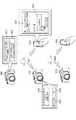
図1を参照して、本発明に係る実施形態のデジタルカメラの構成及び機能の概略について説明する。<Example 1>
The outline of the configuration and function of the digital camera according to the embodiment of the present invention will be described with reference to FIG.
図1において、制御部101は、入力された信号や、後述のプログラムに従ってデジタルカメラ100の各部を制御する。なお、制御部101が装置全体を制御する代わりに、複数のハードウェアが処理を分担することで、装置全体を制御してもよい。 In FIG. 1, the
撮像部102は、撮像部102に含まれるレンズで結像された被写体光を電気信号に変換し、ノイズ低減処理などを行い、デジタルデータを画像データとして出力する。撮像した画像データはバッファメモリに蓄えられた後、制御部101にて所定の演算を行い、記録媒体110に記録される。 The
不揮発性メモリ103は、電気的に消去・記録可能な不揮発性のメモリであり、制御部101で実行される後述のプログラム等が格納される。 The
作業用メモリ104は、撮像部102で撮像された画像データを一時的に保持するバッファメモリや、表示部106の画像表示用メモリ、制御部101の作業領域等として使用される。 The
操作部105は、ユーザがデジタルカメラ100に対する指示をユーザから受け付けるために用いられる。操作部105は例えば、ユーザがデジタルカメラ100の電源のON/OFFを指示するための電源ボタンや、撮影を指示するためのレリーズスイッチ、画像データの再生を指示するための再生ボタンなどの操作部材を含む。また、後述する表示部106に形成されるタッチパネルも操作部105に含まれる。なお、レリーズスイッチは、SW1およびSW2を有する。レリーズスイッチが、いわゆる半押し状態となることにより、SW1がONとなる。これにより、AF(オートフォーカス)処理、AE(自動露出)処理、AWB(オートホワイトバランス)処理、EF(フラッシュプリ発光)処理等の撮影準備を行うための指示を受け付ける。また、レリーズスイッチが、いわゆる全押し状態となることにより、SW2がONとなる。これにより、撮影を行うための指示を受け付ける。 The
表示部106は、撮影の際のビューファインダー画像の表示、撮影した画像データの表示、対話的な操作画面のための文字表示などを行う。なお、表示部106は必ずしもデジタルカメラ100が内蔵する必要はない。デジタルカメラ100は内部又は外部の表示部106と接続することができ、表示部106の表示を制御する表示制御機能を少なくとも有していればよい。 The
記録媒体110は、撮像部102から出力された画像データを記録することができる。記録媒体110は、デジタルカメラ100に着脱可能なよう構成してもよいし、デジタルカメラ100に内蔵されていてもよい。すなわち、デジタルカメラ100は少なくとも記録媒体110にアクセスする手段を有していればよい。 The
接続部111は、外部装置と接続するためのインターフェースである。本実施形態のデジタルカメラ100は、接続部111を介して、外部装置とデータのやりとりを行うことができる。なお、本実施形態では、接続部111は外部装置と無線LANで通信するためのインターフェースを含む。制御部101は、接続部111を制御することで外部装置との無線通信を実現する。なお、通信方式は無線LANに限定されるものではない。 The
なお、本実施形態におけるデジタルカメラ100は、無線LANのインフラストラクチャモードにおけるスレーブ装置として動作することが可能である。スレーブ装置として動作する場合、周辺のアクセスポイント(以下、AP)に接続することで、APが形成するネットワークに参加することが可能である。また、本実施形態におけるデジタルカメラ100は、APの一種ではあるが、より機能が限定された簡易的なAP(以下、簡易AP)として動作することも可能である。なお、本実施形態におけるAPは中継装置の一例である。デジタルカメラ100が簡易APとして動作すると、デジタルカメラ100は自身でネットワークを形成する。デジタルカメラ100の周辺の装置は、デジタルカメラ100をAPと認識し、デジタルカメラ100が形成したネットワークに参加することが可能となる。上記のようにデジタルカメラ100を動作させるためのプログラムは不揮発性メモリ103に保持されているものとする。 The
なお、本実施形態におけるデジタルカメラ100はAPの一種であるものの、スレーブ装置から受信したデータをインターネットプロバイダなどに転送するゲートウェイ機能は有していない簡易APである。したがって、自機が形成したネットワークに参加している他の装置からデータを受信しても、それをインターネットなどのネットワークに転送することはできない。なお、他の実施形態として、デジタルカメラ100にゲートウェイ機能を持たせることも可能である。 Although the
近接無線接続部112は、例えば無線通信のためのアンテナと無線信号を処理するため変復調回路や通信コントローラから構成される。近接無線接続部112は、変調した無線信号をアンテナから出力し、またアンテナで受信した無線信号を復調することでISO/IEC 18092の規格(いわゆるNFC:Near Field Communication)に従った非接触近接通信を実現する。本実施形態の近接無線接続部112は、デジタルカメラ100の側部に配される。 The proximity
後述する外部機器装置200とは、互いの近接無線接続部を近接させることにより通信を開始して接続される。なお、近接無線接続部を用いて接続させる場合、必ずしも近接無線接続部同士を接触させる必要はない。近接無線接続部は一定の距離だけ離れていても通信することができるため、互いの機器を接続するためには、近接無線通信可能な範囲まで近づければよい。以下の説明では、この近接無線通信可能な範囲まで近づけることを、近接させる、とも記載する。 Communication is started and connected to the
また、互いの近接無線接続部が近接無線通信不可能な範囲にあれば、通信は開始されない。また、互いの近接無線接続部が近接無線通信可能な範囲にあって、デジタルカメラ100同士が通信接続されている際に、互いの近接無線接続部112が近接無線通信不可能な範囲に離れてしまった場合は、通信接続が解除される。なお、近接無線接続部112が実現する非接触近接通信はNFCに限られるものではなく、他の無線通信を採用してもよい。例えば、近接無線通信部112が実現する非接触近接通信としてISO/IEC 14443の規格に従った非接触近接通信を採用してもよい。 Further, if the proximity wireless connections of each other are within the range where the proximity wireless communication is impossible, the communication is not started. Further, when the close radio connection units of each other are in the range where the close radio communication is possible and the
近距離無線接続部113は、例えば無線通信のためのアンテナと無線信号を処理するため変復調回路や通信コントローラから構成される。近距離無線通信部113は、変調した無線信号をアンテナから出力し、またアンテナで受信した無線信号を復調することによりIEEE802.15の規格(いわゆるBluetooth(登録商標))に従った近距離無線通信を実現する。本実施形態においてBluetooth(登録商標)通信は、低消費電力であるBluetooth(登録商標) Low Energyのバージョン4.0を採用する。このBluetooth(登録商標)通信は、無線LAN通信と比べて通信可能な範囲が狭い(つまり、通信可能な距離が短い)。また、Bluetooth(登録商標)通信は、無線LAN通信と比べて通信速度が遅い。その一方で、Bluetooth(登録商標)通信は、無線LAN通信と比べて消費電力が少ない。 The short-range
次に、図2を参照して、本発明の外部機器装置200の構成及び機能について説明する。なお、以下では、本発明の外部機器装置の一例として携帯端末について述べるが、これに限られない。本発明は、例えば無線機能付きのデジタルカメラ、携帯型のメディアプレーヤやいわゆるタブレットデバイス、パーソナルコンピュータ、スマートフォンなどの情報処理装置にも適用できる。 Next, the configuration and function of the
図2において、制御部201は、入力された信号や、後述のプログラムに従って外部機器装置200の各部を制御する。なお、制御部201が装置全体を制御する代わりに、複数のハードウェアが処理を分担することで、装置全体を制御してもよい。 In FIG. 2, the
撮像部202は、撮像部202に含まれるレンズで結像された被写体光を電気信号に変換し、ノイズ低減処理などを行い、デジタルデータを画像データとして出力する。撮像した画像データはバッファメモリに蓄えられた後、制御部201にて所定の演算を行い、記録媒体210に記録される。 The
不揮発性メモリ203は、電気的に消去・記録可能な不揮発性のメモリであり、制御部201で実行される各種プログラム等が格納される。デジタルカメラ100と通信するためのプログラムも不揮発性メモリ203に保持され、カメラ通信アプリケーションとしてインストールされているものとする。なお、本実施形態における外部機器装置200の処理は、カメラ通信アプリケーションにより提供されるプログラムを読み込むことにより実現される。なお、カメラ通信アプリケーションは外部機器装置200にインストールされたOSの基本的な機能を利用するためのプログラムを有しているものとする。なお、外部機器装置200のOSが本実施形態における処理を実現するためのプログラムを有していてもよい。 The
作業用メモリ204は、撮像部202で生成された画像データを一時的に保存するバッファメモリや、表示部206の画像表示用メモリや、制御部201の作業領域等として使用される。 The working
操作部205は、外部機器装置200に対する指示をユーザから受け付けるために用いられる。操作部205は例えば、ユーザが外部機器装置200の電源のON/OFFを指示するための電源ボタンや、表示部206に形成されるタッチパネルなどの操作部材を含む。 The
表示部206は、画像データの表示、対話的な操作のための文字表示などを行う。なお、表示部206は必ずしも外部機器装置200が内蔵する必要はない。外部機器装置200は表示部206と接続することができ、表示部206の表示を制御する表示制御機能を少なくとも有していればよい。 The
記録媒体210は、撮像部202から出力された画像データを記録することができる。記録媒体210は、外部機器装置200に着脱可能なよう構成してもよいし、外部機器装置200に内蔵されていてもよい。すなわち、外部機器装置200は少なくとも記録媒体210にアクセスする手段を有していればよい。 The
接続部211は、他外部装置と接続するためのインターフェースである。本実施形態の外部機器装置200は、接続部211を介して、他外部装置とデータのやりとりを行うことができる。なお、本実施形態では、接続部211は他外部装置と無線LANで通信するためのインターフェースを含む。制御部201は、接続部211を制御することで他外部装置との無線通信を実現する。 The
公衆網接続部212は、公衆無線通信を行う際に用いられるインターフェースである。外部機器装置200は、公衆網接続部212を介して、データ通信をすることができる。通話の際には、制御部201はマイク213およびスピーカ214を介して音声信号の入力と出力を行う。本実施形態では、公衆網接続部212は3Gを用いた通信を行うためのインターフェースを含むものとする。なお、3Gに限らず、LTEやWiMAX(登録商標)、ADSL、FTTH、いわゆる4Gといった他の通信方式を用いてもよい。また、接続部131および公衆網接続部212は必ずしも独立したハードウェアで構成する必要はなく、例えば1つのアンテナで兼用することも可能である。 The public
近接無線接続部215は、他外部装置と近接無線接続するためのインターフェースである。本実施形態の外部機器装置200は、近接無線接続部215を介して、他外部装置とデータのやりとりを行うことができる。なお、本実施形態では、近接無線接続部215は他外部装置とNFCで通信するためのインターフェースを含む。制御部201は、近接無線接続部215を制御することで他外部装置とのNFC通信を実現する。 The proximity
近距離無線接続部216は、他外部装置と近距離無線接続するためのインターフェースである。本実施形態の外部機器装置200は、近距離無線接続部216を介して、他外部装置とデータのやりとりを行うことができる。なお、本実施形態では、近距離無線接続部216は他外部装置とBluetooth(登録商標)で通信するためのインターフェースを含む。制御部201は、近距離無線接続部216を制御することで他外部装置とのBluetooth(登録商標)通信を実現する。 The short-range
図3Aを用いてユーザがデジタルカメラ100の操作部105を操作し、表示部106に表示されるユーザインタフェース(以下、UI)を使用してデジタルカメラ100が外部機器装置200と無線LAN接続する場合を説明する。 When the user operates the
デジタルカメラ100の操作部105を操作し、無線LAN(簡易APによる接続)を起動させる。この時表示部106には外部機器装置でユーザに操作してもらうようにメッセージを表示する。例えば“以下のネットワークに接続し、アプリを起動してください”301が画面表示例である。またその際、簡易APとして起動したパラメータSSID,Passwordを表示部106に表示する。302は画面表示例としてSSID:CAMERA_000、Password:12345678としている。デジタルカメラ100にて簡易APを起動したら、外部機器装置200にて無線LANの設定を行う。その際SSIDは‘CAMERA_000’を選択し、Passwordは‘12345678’と入力することで無線LANの接続が完了する。無線LANの接続が完了したら、外部機器装置200にてアプリを起動する。アプリが起動すると、アプリではデジタルカメラを発見する動作をする。デジタルカメラ100が見つかった場合303のような画面を表示部206に表示し、発見されたカメラ一覧としてデジタルカメラの名前が表示される。この名前は予めデジタルカメラに設定したニックネーム等の値が表示される。本実施例では‘CAMERA1’304としている。画面303にてカメラ一覧から所定のデジタルカメラを選択すると、外部機器装置200からデジタルカメラ100に接続要求が行われ、その接続要求をデジタルカメラ100が受信する。デジタルカメラ100が接続要求を受信するとデジタルカメラ100では外部機器装置200と通信してよいか許可を求めるメッセージが表示部106に表示される。305は“XXXXXXと接続します”は画面表示例である。XXXXXXは相手機器の名前が表示される。通信を許可する場合にはOKボタン306を選択することで、デジタルカメラ100から接続許可を外部機器装置200へ返信する。一方通信不許可の場合にはキャンセルボタン307を選択することでデジタルカメラ100から通信不許可を外部機器装置200へ返信する。許可画面は初回の接続時に表示される。2回目以降の接続時は表示されず、接続要求に対し接続許可を送信する。デジタルカメラ100は接続許可の返信を送信することで接続完了となり、外部機器装置200は接続許可の返信を受信することで接続完了となる。 The
次に、図3Bを用いてデジタルカメラ100と外部機器装置200が近接無線通信(NFC)を使用して、無線LANに通信を切り替えて接続する場合について説明する。なお、このように、ある通信方式により得られた情報を用いて他の通信方式に通信を切り替える処理を、本実施形態ではハンドオーバー処理と呼ぶ。 Next, a case where the
デジタルカメラ100の近接無線接続部112と外部機器装置の近接無線接続部215を近接させることでNFCの通信を行う。デジタルカメラ100ではNFC通信を行う前にNFC通信によって無線LANへのハンドオーバーを行うために必要なパラメータを事前に決定しておく。必要なパラメータは例えば無線LANのSSID,Passwordなどである。NFC通信では外部機器装置200がデジタルカメラ100からパラメータを受信する。デジタルカメラ100では外部機器装置200とのNFC通信が完了すると、事前に決定していた無線LANパラメータにて簡易APを形成する。その際外部機器装置200からの接続を待つ動作となり、表示部106にメッセージを表示する。例えば“接続中です。おまちください”308が画面表示例である。外部機器装置200からの接続待ちをキャンセルする場合にはキャンセルボタン309を選択することによってハンドオーバー処理を終了する。一方、外部機器装置200はNFC通信にてパラメータを受信すると受信したパラメータに応じて無線LANの接続を行う。外部機器装置200にて接続動作中の状態を表示部206に表示する。画面表示例は310である。ネットワークの検索は無線LANのSSIDが発見された場合にチェックされる。ネットワークへの接続は無線LAN接続が完了し、IP接続が完了した場合にチェックされる。カメラへの接続はデジタルカメラとの接続が完了した場合にチェックされ、カメラとの接続が完了する。無線LAN接続が完了し、IP接続が完了した後、外部機器装置200から接続要求が行われる。デジタルカメラ100では接続要求を受信し、外部機器装置200と通信してよいか許可を求めるメッセージが表示部106に表示される。“XXXXXXと接続します”は画面表示例311である。XXXXXXは相手機器の名前が表示される。通信を許可する場合にはOKボタン312を選択することで、デジタルカメラ100から接続許可を外部機器装置200へ返信する。一方通信不許可の場合にはキャンセルボタン313を選択することでデジタルカメラ100から通信不許可を外部機器装置200へ返信する。許可画面は初回の接続時に表示される。2回目以降の接続時は表示されず、接続要求に対し接続許可を送信する。デジタルカメラ100は接続許可の返信を送信することで接続完了となり、外部機器装置200は接続許可の返信を受信することで接続完了となる。 NFC communication is performed by bringing the proximity
次に、図3Cを用いてデジタルカメラ100と外部機器装置200がBluetooth(登録商標)を使用して無線LANへのハンドオーバー接続する場合を説明する。 Next, a case where the
デジタルカメラ100の近距離無線通信113と外部機器装置200の近距離無線通信216はBluetooth(登録商標)通信のペアリング処理がなされているものとする。ペアリング処理は一度実施すれば、その後はその通信範囲内にあればBluetooth(登録商標)通信は自動的に接続可能である。315はBluetooth(登録商標)通信が確立していることを示している。またデジタルカメラ100ではBluetooth(登録商標)通信が確立した際に、無線LANへのハンドオーバーを行うための必要なパラメータを外部機器装置200に送信し共有しておく。必要なパラメータは例えば無線LANのSSID,Passwordなどである。 It is assumed that the short-
314は近距離無線通信の接続が完了している場合に外部機器装置200の表示部206に表示される画面表示例である。画像表示ボタンはデジタルカメラ100内の記録媒体110に記録されている画像を表示するボタンである。リモートLVはデジタルカメラ100の撮像部102で撮影された画像をリアルタイムに表示するボタンである。いずれかのボタンを操作することで無線LANへのハンドオーバーの処理が開始される。ハンドオーバー処理が開始されると、Bluetooth(登録商標)通信によって外部機器装置200からデジタルカメラ100にハンドオーバー要求を送信する。デジタルカメラ100は外部機器装置200からのハンドオーバー要求を受信すると、ハンドオーバー可能かどうかを判定しその結果を返信する。ハンドオーバーが可能である場合には、Bluetooth(登録商標)通信を切断し、事前に共有していた無線LANパラメータに応じて簡易APを形成する。その際外部機器装置200からの接続を待つ動作となり、表示部106にメッセージを表示する。例えば“接続中です。おまちください”317が画面表示例である。外部機器装置200からの接続待ちをキャンセルする場合にはキャンセルボタン318を選択することによってハンドオーバー処理を終了する。一方外部機器装置200はBluetooth(登録商標)通信にて事前に受信した無線パラメータに応じて無線LANの接続を行う。その際の画面表示例が316である。外部機器装置200にて無線LAN接続が完了し、IP接続が完了した後、外部機器装置200から接続要求が行われる。デジタルカメラ100では接続要求を受信すると、接続許可を送信する。デジタルカメラ100は接続許可の返信を送信することで接続完了となり、外部機器装置200は接続許可の返信を受信することで接続完了となる。
図4は上記のいずれかで接続した際に接続が完了した外部機器装置200の画面表示例である。400は無線LAN接続中であることを示し、SSIDがCAMERA_000であることを示している。 FIG. 4 is a screen display example of the
デジタルカメラ100と外部機器装置200が無線LANで接続した後、電波環境の悪化や何らかの要因によって通信エラーが発生しそれを検知した場合にデジタルカメラ100は無線LANで再接続処理を行う。再接続処理はデジタルカメラ100が高所等に設置されている状況で外部機器装置200との通信がエラーとなってしまった場合、デジタルカメラ100の操作をせずに再接続をできるようにするためである。 After the
一方外部機器装置200はデジタルカメラ100との無線LAN接続以外に、インターネット等に接続するための自宅のAP等に接続していることがある。その場合、外部機器装置200はデジタルカメラ100との無線LAN接続が切れてしまうと自宅のAPに接続してしまう可能性がある。このような状況ではデジタルカメラ100がいくら再接続を試みても外部機器装置200との再接続が成功しない。また、デジタルカメラ100は無線LANを起動し続けてしまうため、電力を消費してしまう。デジタルカメラ100に無線LANよりも電力消費の少ないBluetooth(登録商標)を有する場合、Bluetooth(登録商標)通信が可能であればBluetooth(登録商標)通信に切り替える。そしてBluetooth(登録商標)通信によって無線LANへのハンドオーバーを試みることによって、再接続が可能になる。 On the other hand, the
そこで本実施例では、接続形態に基づいて切断時に無線LAN接続をリトライするか、Bluetooth(登録商標)通信に切り替えるかを判定し、再接続処理を行うこととした。 Therefore, in this embodiment, it is determined whether to retry the wireless LAN connection at the time of disconnection or to switch to Bluetooth (registered trademark) communication based on the connection form, and to perform the reconnection process.
図5はデジタルカメラ100の操作部105を操作し、表示部106に表示されるUIを使用してデジタルカメラ100が外部機器装置200と無線LAN接続する場合のデジタルカメラ100の処理フロー図である。 FIG. 5 is a processing flow diagram of the
[UIからの手動接続処理フロー]
ステップS501では、制御部101は接続部111を介して無線LANを起動する。無線LANの起動が完了したら制御部101は処理をS502に進める。本実施例では無線LANを形成し簡易APを起動する処理としているが、APを検索し、発見したAPに参加する処理としてもよい。[Manual connection processing flow from UI]
In step S501, the
ステップS502では、制御部101は表示部106にS501にて形成した簡易APのパラメータ情報であるSSID,Passwordを表示する。301、302は画面表示例である。APに参加する処理である場合には、そのAPのSSIDを表示するようにしてもよい。表示後、制御部101は処理をS503に進める。 In step S502, the
ステップS503では、制御部101は接続部111を介して、外部機器装置200から接続要求があるかどうかを判定する。接続要求の情報は外部機器装置の機器名及び機器識別情報であるUUIDが含まれる。接続要求がある場合には制御部101は処理をS504に進める。接続要求がない場合には制御部101は処理をS502に進める。 In step S503, the
ステップS504では、制御部101は接続履歴があるかどうかを判定する。接続履歴の判定は後述するS509の機器情報保持で保持された情報にS503の接続要求情報のUUIDが含まれているかどうかで判定する。接続履歴がある場合には、制御部101は処理をS505に進める。接続履歴がない場合には、制御部101は処理をS506に進める。 In step S504, the
ステップS505では、制御部101は接続部111を介して接続要求に対する接続許可を外部機器装置200に送信する。送信後制御部101は処理をS508に進める。 In step S505, the
ステップS506では、制御部101は接続許可を促す画面を表示部106に表示する。305はその画面表示例である。表示後、制御部101は処理をS507へ進める。 In step S506, the
ステップS507では、制御部101は操作部105によって操作され接続許可かどうかを判定する。画面表示例の接続許可画面でOKボタン306を選択した場合、制御部101は処理をS505へ進める。画面表示例の接続許可画面でキャンセルボタン307を選択した場合、制御部101は接続終了処理を行い、動作を終了する。 In step S507, the
ステップS508では、制御部101は接続形態情報を一時的に保持するため、作業用メモリ104に接続形態情報を保持する。今回のフローではUIでの手動接続であるため、UI手動接続であるという情報を作業用メモリ104に保持する。接続形態情報を保持したら、制御部101は処理をS509に進める。 In step S508, the
ステップS509では、制御部101は機器情報を保持するため、不揮発性メモリ103に機器情報を保持する。機器情報は外部機器装置の機器名及び機器識別情報であるUUIDを保持する。ただし、すでに同一の機器情報が存在する場合には保持しない。機器情報を保持したら、制御部101は接続完了とし処理を終了する。 In step S509, the
図6はデジタルカメラ100と外部機器装置200が近接無線通信(NFC)を使用して無線LAN接続する場合のデジタルカメラ100のハンドオーバー接続処理フロー図である。 FIG. 6 is a handover connection processing flow diagram of the
デジタルカメラ100の近接無線接続部112と外部機器装置の近接無線接続部215を近接させることでNFCの通信を行う。NFC通信が行われたことをトリガに接続動作を開始する。 NFC communication is performed by bringing the proximity
[NFCからのハンドオーバー接続処理フロー]
ステップS601では、制御部101は簡易APとして無線LANを形成する。その際の無線LANを形成するパラメータ(SSID、Passwordなど)はNFC通信にて外部機器装置200に渡した無線パラメータを使用する。無線LANを形成したら、制御部101は処理をS602に進める。[Handover connection processing flow from NFC]
In step S601, the
ステップS602では、制御部101は接続部111を介して、外部機器装置200から接続要求があるかどうかを判定する。接続要求の情報は外部機器装置の機器名及び機器識別情報であるUUIDが含まれる。接続要求がある場合には制御部101は処理をS603に進める。接続要求がない場合には再度接続要求があるかどうかを判定する。 In step S602, the
ステップS603では、制御部101は接続履歴があるかどうかを判定する。接続履歴は機器情報保持で保持された情報にS602の接続要求情報に含まれるUUIDが含まれているかどうかで判定する。接続履歴がある場合には、制御部101は処理をS604に進める。接続履歴がない場合には、制御部101は処理をS605に進める。 In step S603, the
ステップS604では、制御部101は接続部111を介して接続要求に対する接続許可を外部機器装置200に送信する。送信後制御部101は処理をS607に進める。 In step S604, the
ステップS605では、制御部101は接続許可を促す画面を表示部106に表示する。311はその画面表示例である。表示後、制御部101は処理をS606へ進める。 In step S605, the
ステップS606では、制御部101は操作部105によって操作され接続許可かどうかを判定する。画面表示例の接続許可画面でOKボタン312を選択した場合、制御部101は処理をS604へ進める。画面表示例の接続許可画面でキャンセルボタン313を選択した場合、制御部101は接続終了処理を行い、動作を終了する。 In step S606, the
ステップS607では、制御部101は接続形態情報を一時的に保持するため、作業用メモリ104に接続形態情報を保持する。今回のフローではNFCでの接続であるため、NFC接続であるという情報を作業用メモリ104に保持する。接続形態情報を保持したら、制御部101は処理をS608に進める。 In step S607, in order to temporarily hold the connection form information, the
ステップS608では、制御部101は機器情報を保持するため、不揮発性メモリ103に機器情報を保持する。機器情報は外部機器装置の機器名及び機器識別情報であるUUIDを保持する。ただし、すでに同一の機器情報が存在する場合には保持しない。機器情報を保持したら、制御部101は接続完了とし処理を終了する。 In step S608, the
図7はデジタルカメラ100と外部機器装置200のBluetooth(登録商標)接続処理フローとデジタルカメラ100と外部機器装置200がBluetooth(登録商標)を使用して無線LAN接続する場合のデジタルカメラ100のハンドオーバー接続処理フロー図である。 FIG. 7 shows the Bluetooth (registered trademark) connection processing flow of the
デジタルカメラ100の近距離無線通信113と外部機器装置200の近距離無線通信216によってBluetooth(登録商標)通信のペアリング処理がなされ、外部機器装置200からのハンドオーバー要求を受信することで接続動作を開始する。 Bluetooth (registered trademark) communication is paired by the short-
[Bluetooth(登録商標)接続処理フロー]
ステップS710では、制御部101はペアリング処理を実行する。ペアリング処理を終えると制御部101は処理をS711に進める。[Bluetooth (registered trademark) connection processing flow]
In step S710, the
ステップS711では、制御部101はペアリング情報を保持するため、不揮発性メモリ103に機器情報を保持する。ペアリング情報には機器識別情報であるUUIDを含む。ただし、すでに同一の機器情報が存在する場合には保持しない。ペアリング情報を保持したら、制御部101は接続完了とする。 In step S711, the
[Bluetooth(登録商標)からのハンドオーバー接続処理フロー]
ステップS701では、制御部101は簡易APとして無線LANを形成する。その際の無線LANを形成するパラメータ(SSID、Passwordなど)は事前にBluetooth(登録商標)通信にて外部機器装置200に渡した無線パラメータを使用する。無線LANを形成したら、制御部101は処理をS702に進める。[Handover connection processing flow from Bluetooth (registered trademark)]
In step S701, the
ステップS702では、制御部101は接続部111を介して、外部機器装置200から接続要求があるかどうかを判定する。接続要求の情報は外部機器装置の機器名及び機器識別情報であるUUIDが含まれる。接続要求がある場合には制御部101は処理をS703に進める。接続要求がない場合には再度接続要求があるかどうかを判定する。 In step S702, the
ステップS703では、制御部101は接続部111を介して接続要求に対する接続許可を外部機器装置200に送信する。送信後制御部101は処理をS704に進める。 In step S703, the
ステップS704では、制御部101は接続形態情報を一時的に保持するため、作業用メモリ104に接続形態情報を保持する。今回のフローではBluetooth(登録商標)での接続であるため、Bluetooth(登録商標)接続であるという情報を作業用メモリ104に保持する。接続形態情報を保持したら、制御部101は処理をS705に進める。 In step S704, the
ステップS705では、制御部101は機器情報を保持するため、不揮発性メモリ103に機器情報を保持する。機器情報は外部機器装置の機器名及び機器識別情報であるUUIDを保持する。ただし、すでに同一の機器情報が存在する場合には保持しない。機器情報を保持したら、制御部101は接続完了とし処理を終了する。 In step S705, the
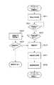
図8はデジタルカメラ100と外部機器装置200との間で何かしらの理由により無線LANの通信エラーが発生した場合のデジタルカメラ100の処理フロー図である。図9(a)はBluetooth(登録商標)を利用していない場合の外部機器装置200の再接続中の画面表示例901であり、図9(b)はBluetooth(登録商標)を利用した場合の外部機器装置200の再接続中の画面表示例902である。 FIG. 8 is a processing flow diagram of the
ステップS801では、制御部101は切断を検出し、作業用メモリ104に保持している接続形態情報を参照し、接続形態がBluetooth(登録商標)接続かどうかを判定する。接続形態がBluetooth(登録商標)接続であれば制御部101は処理をS802に進める。接続形態がBluetooth(登録商標)接続でなければ制御部101は処理をS804に進める。この判定をする理由は、接続形態がBluetooth(登録商標)接続である場合には、外部機器装置200とのBluetooth(登録商標)接続を一度しており、再度Bluetooth(登録商標)接続ができる可能性が高いためである。 In step S801, the
ステップS802では、制御部101は無線LANを切断し、無線LANの終了処理を実行する。処理後制御部101は処理をS803に進める。 In step S802, the
ステップS803では、制御部101はBluetooth(登録商標)を起動し接続をする。Bluetooth(登録商標)はすでにペアリング済みであり、通信範囲内に外部機器装置200が存在すればBluetooth(登録商標)は接続が可能である。通信範囲内に外部機器装置200が存在しない場合には、Bluetooth(登録商標)接続待ち状態で待機する。Bluetooth(登録商標)接続待機状態は低消費電力で動作することが可能である。デジタルカメラ100が一度待機状態になった場合であっても、外部機器装置200との距離がBluetooth(登録商標)の通信範囲に入ることで自動的にBluetooth(登録商標)接続を完了することができる。Bluetooth(登録商標)接続が完了すると外部機器装置は図3Cの314が表示される。外部機器装置200によってハンドオーバー処理が実行されるとデジタルカメラ100は図7のBluetooth(登録商標)からのハンドオーバー接続処理フローが実行される。 In step S803, the
ステップS804では、制御部101は無線LANの再接続処理を行う。簡易APであれば再度ネットワークを形成し、外部機器装置200のネットワーク参加及び外部機器装置200からの接続要求を待つ。またAPへの接続であれば、ネットワークに参加し外部機器装置200からの接続要求を待つ。無線LANの再接続処理後、制御部101は処理をS805に進める。 In step S804, the
ステップS805では、制御部101は再接続成功かどうかを判定する。再接続成功かどうかの判定はまず無線LANの接続が成功したかどうかを判定し、無線LAN接続が成功した場合には外部機器装置200からの接続要求が来たかどうかで判定する。無線LANの接続が失敗した場合には再接続失敗と見なす。再接続成功と判定された場合には制御部101は再接続処理を終了し、通信を再開させる。タイムアウト等により再接続失敗と判定された場合には制御部101は処理をS806に進める。 In step S805, the
ステップS806では、制御部101は再接続処理がリトライ回数の上限に達しているかどうかを判定する。リトライ回数の上限に達している場合には制御部101は通信エラーとし、エラー処理を実行し処理を終了する。リトライ回数の上限に達していない場合には制御部101は処理をS804に進める。 In step S806, the
以上説明したように、本実施形態では、デジタルカメラ100と外部機器装置200との間で何らかしらの理由により通信エラーが発生した場合、接続形態がBluetooth(登録商標)接続であるかどうかによって再接続を切り替える。このことにより、接続形態がBluetooth(登録商標)である場合には電力消費を抑えることができる。 As described above, in the present embodiment, when a communication error occurs between the
<実施例2>
実施例1ではデジタルカメラ100の図8のステップS801にて接続形態がBluetooth(登録商標)接続かどうかのみで判定していた。その判定処理に加えていくつか条件を加えた判定処理結果を示す表が図10である。<Example 2>
In the first embodiment, in step S801 of FIG. 8 of the
以下に図10を用いてその判定条件の説明をする。 The determination conditions will be described below with reference to FIG.
1001、1002,1003はそれぞれ実施例1にて作業用メモリ104に保持された接続形態であるUI手動接続、NFC、Bluetooth(登録商標)を示している。1004の行はデジタルカメラ100におけるBluetooth(登録商標)を使用するかどうかの設定値を示す。1005の行は不揮発性メモリ103に保持しているペアリング情報と接続機器情報が一致しているかどうかを示す。ペアリング情報はBluetooth(登録商標)接続時に必要な情報であり、機器識別情報であるUUIDを含んでいる。例えばデジタルカメラ100がBluetooth(登録商標)を使用する設定になっている状態“Bluetooth(登録商標)を使用する”(1004)で外部機器装置200と接続している場合を考える。その際の接続形態が“UI接続”(1001)でペアリング情報に含まれているUUIDの値と、接続している機器情報に含まれるUUIDの値が一致している場合“ペアリング情報一致”(1005)には、“Bluetooth(登録商標)への切り替え“(1006)という判定がなされる。このような判定条件にすることで、接続形態がBluetooth(登録商標)接続でない場合であっても、Bluetooth(登録商標)による再接続処理を行うことができ、電力消費を抑えることができる。 1001, 1002, and 1003 indicate UI manual connection, NFC, and Bluetooth (registered trademark), which are the connection forms held in the working
<実施例3>
実施例1ではデジタルカメラ100の図8のステップS803の処理中に外部機器装置200は図9(b)を表示していた。外部機器装置200ではBluetooth(登録商標)が接続完了した後、再度無線LANへのハンドオーバー処理を開始するために画像表示ボタン又はリモートLVボタンをユーザが操作する必要がある。そのため接続の状態をユーザが気づかない可能性がある。<Example 3>
In the first embodiment, the
そこで本実施例では、無線LAN通信がエラーになり、Bluetooth(登録商標)通信による再接続が完了した場合に、自動的に無線LANへのハンドオーバー接続処理をするようにした。自動で無線LANへのハンドオーバー接続処理を行うことによってユーザの操作なしに再接続処理が可能である。 Therefore, in this embodiment, when the wireless LAN communication becomes an error and the reconnection by Bluetooth (registered trademark) communication is completed, the handover connection process to the wireless LAN is automatically performed. By automatically performing the handover connection process to the wireless LAN, the reconnection process can be performed without any user operation.
また通信エラーによって外部機器装置200が別のAPに接続してしまった場合でも、自動的に無線LANへのハンドオーバー接続処理を開始することで、ユーザが意識することなく再接続できる。 Further, even if the
以上、本発明の好ましい実施形態について説明したが、本発明はこれらの実施形態に限定されず、その要旨の範囲内で種々の変形及び変更が可能である。 Although the preferred embodiments of the present invention have been described above, the present invention is not limited to these embodiments, and various modifications and modifications can be made within the scope of the gist thereof.
また、本発明は、以下の処理を実行することによっても実現される。即ち、上述した実施形態の機能を実現するソフトウェア(プログラム)を、ネットワーク又は各種記憶媒体を介してシステム或いは装置に供給し、そのシステム或いは装置のコンピュータ(またはCPUやMPU等)がプログラムを読み出して実行する処理である。 The present invention is also realized by executing the following processing. That is, software (program) that realizes the functions of the above-described embodiment is supplied to the system or device via a network or various storage media, and the computer (or CPU, MPU, etc.) of the system or device reads the program. This is the process to be executed.
Claims (10)
Translated fromJapanese前記通信装置は、第1の通信手段と、第2の通信手段を有し、
前記第1の通信手段の通信を確立するための接続形態を保持する保持手段と、
前記第1の通信手段の通信エラーを検知した際、前記保持手段で保持した接続形態に応じて前記第2の通信手段に切り替えるか、前記第1の通信手段で再接続するかを判定する判定手段とを有することを特徴とする通信装置。A communication device that connects to an external device via a network.
The communication device has a first communication means and a second communication means.
A holding means for holding a connection form for establishing communication of the first communication means, and
When a communication error of the first communicationmeans is detected, it is determined whether to switch to the second communication means or reconnect with the first communication means according to the connection form held by the holding means. A communication device characterized by having means.
第1の通信手段は無線LANであることを特徴とする請求項1に記載の通信装置。A communication device that connects to an external device via a network.
The communication device according to claim 1, wherein the first communication means is a wireless LAN.
第2の通信手段はBluetoothであることを特徴とする請求項1に記載の通信装置。A communication device that connects to an external device via a network.
The communication device according to claim 1, wherein the second communication means is Bluetooth.
前記接続形態はユーザインタフェースからの手動接続、NFCからのハンドオーバー、Bluetoothからのハンドオーバーのいずれかであることを特徴とする請求項1に記載の通信装置。A communication device that connects to an external device via a network.
The communication device according to claim 1, wherein the connection form is any one of manual connection from a user interface, handover from NFC, and handover from Bluetooth.
前記判定手段は前記接続形態がBluetoothからのハンドオーバーであるかどうかを判定することを特徴とする請求項1に記載の通信装置。A communication device that connects to an external device via a network.
The communication device according to claim 1, wherein the determination means determines whether or not the connection form is a handover from Bluetooth.
外部機器装置の接続機器情報を保持する手段をさらに有することを特徴とする請求項1に記載の通信装置。A communication device that connects to an external device via a network.
The communication device according to claim 1, further comprising means for holding connection device information of the external device device.
Bluetooth接続に必要なペアリング情報を保持する手段をさらに有することを特徴とする請求項1に記載の通信装置。A communication device that connects to an external device via a network.
The communication device according to claim 1, further comprising a means for holding pairing information necessary for Bluetooth connection.
前記判定手段は前記接続形態にかかわらず前記ペアリング情報と前記接続機器情報が一致するかどうかを判定することを特徴とする請求項1に記載の通信装置。A communication device that connects to an external device via a network.
The communication device according to claim 1, wherein the determination means determines whether or not the pairing information and the connected device information match regardless of the connection form.
前記第1の通信手段の通信を確立するための接続形態を保持する保持工程と、
前記第1の通信手段の通信エラーを検知した際、前記保持工程で保持した接続形態に応じて前記第2の通信手段に切り替えるか、前記第1の通信手段で再接続するかを判定する判定工程とを有することを特徴とする通信装置の制御方法。A method for controlling a communication device having a first communication means and a second communication means and connecting to an external device via a network.
A holding step for holding a connection form for establishing communication of the first communication means, and
When a communication error of the first communicationmeans is detected, it is determined whether to switch to the second communication means or reconnect with the first communication means according to the connection form held in the holding step. A method for controlling a communication device, which comprises a process.
Priority Applications (2)
| Application Number | Priority Date | Filing Date | Title |
|---|---|---|---|
| JP2017031500AJP6869746B2 (en) | 2017-02-22 | 2017-02-22 | Communication device, its control method, program |
| US15/892,191US10616816B2 (en) | 2017-02-22 | 2018-02-08 | Communication apparatus, method for controlling same, and storage medium |
Applications Claiming Priority (1)
| Application Number | Priority Date | Filing Date | Title |
|---|---|---|---|
| JP2017031500AJP6869746B2 (en) | 2017-02-22 | 2017-02-22 | Communication device, its control method, program |
Publications (2)
| Publication Number | Publication Date |
|---|---|
| JP2018137647A JP2018137647A (en) | 2018-08-30 |
| JP6869746B2true JP6869746B2 (en) | 2021-05-12 |
Family
ID=63167568
Family Applications (1)
| Application Number | Title | Priority Date | Filing Date |
|---|---|---|---|
| JP2017031500AActiveJP6869746B2 (en) | 2017-02-22 | 2017-02-22 | Communication device, its control method, program |
Country Status (2)
| Country | Link |
|---|---|
| US (1) | US10616816B2 (en) |
| JP (1) | JP6869746B2 (en) |
Families Citing this family (11)
| Publication number | Priority date | Publication date | Assignee | Title |
|---|---|---|---|---|
| JP2021108426A (en)* | 2019-12-27 | 2021-07-29 | スター精密株式会社 | Connector-interface switch control device and program for controlling connector interface switching |
| CN114554464B (en)* | 2020-03-26 | 2022-12-13 | 华为技术有限公司 | A data sharing and instruction operation control method and system |
| CN112654020B (en)* | 2020-12-15 | 2023-03-28 | 阿波罗智联(北京)科技有限公司 | Method, device, equipment and storage medium for establishing wireless connection |
| JP2023175073A (en)* | 2022-05-30 | 2023-12-12 | 株式会社三洋物産 | Game machine |
| JP2023175069A (en)* | 2022-05-30 | 2023-12-12 | 株式会社三洋物産 | Game machine |
| JP2023175072A (en)* | 2022-05-30 | 2023-12-12 | 株式会社三洋物産 | Game machine |
| JP2023175070A (en)* | 2022-05-30 | 2023-12-12 | 株式会社三洋物産 | Game machine |
| JP2023176856A (en)* | 2022-06-01 | 2023-12-13 | 株式会社三洋物産 | Game machine |
| JP2023176854A (en)* | 2022-06-01 | 2023-12-13 | 株式会社三洋物産 | Game machine |
| JP2023176855A (en)* | 2022-06-01 | 2023-12-13 | 株式会社三洋物産 | Game machine |
| JP2023176853A (en)* | 2022-06-01 | 2023-12-13 | 株式会社三洋物産 | Game machine |
Family Cites Families (17)
| Publication number | Priority date | Publication date | Assignee | Title |
|---|---|---|---|---|
| JPH10224845A (en)* | 1997-02-03 | 1998-08-21 | Nec Telecom Syst Ltd | Personal handy phone system and its speech changeover method |
| KR100657258B1 (en)* | 2002-07-02 | 2006-12-14 | 삼성전자주식회사 | Bluetooth wifi connection device and method |
| JP2004289373A (en)* | 2003-03-20 | 2004-10-14 | Tdk Corp | Wireless communication system, wireless terminal device, and method for switching communication system |
| US7717342B2 (en)* | 2005-08-26 | 2010-05-18 | Hand Held Products, Inc. | Data collection device having dynamic access to multiple wireless networks |
| US7899396B2 (en)* | 2006-06-02 | 2011-03-01 | Qulacomm Incorporated | Efficient operation for co-located WLAN and Bluetooth |
| WO2008067505A2 (en)* | 2006-11-30 | 2008-06-05 | Conexant Systems, Inc. | Systems and methods for coexistence of wlan and bluetooth networks |
| US8554137B2 (en)* | 2007-02-12 | 2013-10-08 | Broadcom Corporation | Method and system for short range and wireless LAN coexistence |
| CA2738152A1 (en)* | 2008-09-22 | 2010-03-25 | Jumpstart Wireless Corporation | System and method for dynamic automatic communication path selection, distributed device synchronization and task delegation |
| JP5117352B2 (en)* | 2008-11-07 | 2013-01-16 | 株式会社東芝 | Wireless communication apparatus and wireless communication method |
| US8594056B2 (en)* | 2009-06-16 | 2013-11-26 | Qualcomm Incorporated | Method and apparatus for dynamic and dual antenna bluetooth (BT)/WLAN coexistence |
| JP5366876B2 (en)* | 2010-04-20 | 2013-12-11 | 日本電信電話株式会社 | Wireless communication method |
| US9078079B2 (en)* | 2011-10-07 | 2015-07-07 | Lg Electronics Inc. | Multi-network access method and communication device thereof |
| JP2013150177A (en) | 2012-01-19 | 2013-08-01 | Canon Inc | Image processing system and control method therefor |
| US9414430B2 (en)* | 2013-08-16 | 2016-08-09 | Qualcomm, Incorporated | Techniques for managing radio link failure recovery for a user equipment connected to a WWAN and a WLAN |
| US9648518B2 (en)* | 2015-03-06 | 2017-05-09 | Apple Inc. | Dynamic selection of coexistence profiles for improved Wi-Fi/bluetooth coexistence |
| JP6376015B2 (en)* | 2015-03-24 | 2018-08-22 | ソニー株式会社 | Information processing apparatus, information processing method, and program |
| EP3151599A1 (en)* | 2015-09-30 | 2017-04-05 | Apple Inc. | Authentication failure handling for cellular network access through wlan |
- 2017
- 2017-02-22JPJP2017031500Apatent/JP6869746B2/enactiveActive
- 2018
- 2018-02-08USUS15/892,191patent/US10616816B2/enactiveActive
Also Published As
| Publication number | Publication date |
|---|---|
| US20180242215A1 (en) | 2018-08-23 |
| US10616816B2 (en) | 2020-04-07 |
| JP2018137647A (en) | 2018-08-30 |
Similar Documents
| Publication | Publication Date | Title |
|---|---|---|
| JP6869746B2 (en) | Communication device, its control method, program | |
| US9807222B2 (en) | Communication apparatus, method of controlling same, and storage medium | |
| US20150092764A1 (en) | Communication apparatus, data processing apparatus, control method thereof, and recording medium | |
| JP2016029788A (en) | COMMUNICATION DEVICE, COMMUNICATION DEVICE CONTROL METHOD, PROGRAM | |
| US10298831B2 (en) | Image capturing apparatus and method of controlling same with notification whether to stop moving image recording | |
| JP6433265B2 (en) | Information processing apparatus, electronic device, control method thereof, program, and storage medium | |
| JP6385078B2 (en) | COMMUNICATION DEVICE, COMMUNICATION DEVICE CONTROL METHOD, PROGRAM | |
| JP6821360B2 (en) | Electronic devices and their control methods | |
| JP6810555B2 (en) | Wireless communication equipment and its control method, and wireless communication system | |
| JP6463050B2 (en) | COMMUNICATION DEVICE, ITS CONTROL METHOD, AND PROGRAM | |
| JP2017103650A (en) | Communication device, communication device control method, and program | |
| US10028191B2 (en) | System and method for dual mode communication between communication devices | |
| US9560476B2 (en) | Wireless communication apparatus capable of communicating with external apparatus, controlling method for wireless communication apparatus, and storage medium | |
| US12108290B2 (en) | Apparatus, method of same, and storage medium for wirelessly communicating with external device via a plurality of wireless communication methods | |
| US11711610B2 (en) | Communication apparatus, control method, and recording medium | |
| US11917705B2 (en) | Communication apparatus that communicates with other devices via network, control method, and storage medium | |
| US20240107400A1 (en) | Communication device, communication method, and communication system | |
| JP2014049800A (en) | Communication device, its control method and program | |
| JP7479908B2 (en) | COMMUNICATION DEVICE, CONTROL METHOD FOR COMMUNICATION DEVICE, AND PROGRAM | |
| JP2017085518A (en) | Communication apparatus, control method for communication apparatus, and program | |
| JP2024124182A (en) | COMMUNICATION DEVICE, CONTROL METHOD AND PROGRAM FOR COMMUNICATION DEVICE | |
| WO2023074132A1 (en) | Wireless communication device and control method therefor | |
| JP2021022797A (en) | Communication device | |
| JP2019193069A (en) | Communication device, and control method and program therefor |
Legal Events
| Date | Code | Title | Description |
|---|---|---|---|
| A621 | Written request for application examination | Free format text:JAPANESE INTERMEDIATE CODE: A621 Effective date:20200218 | |
| A977 | Report on retrieval | Free format text:JAPANESE INTERMEDIATE CODE: A971007 Effective date:20201110 | |
| A131 | Notification of reasons for refusal | Free format text:JAPANESE INTERMEDIATE CODE: A131 Effective date:20210105 | |
| A521 | Request for written amendment filed | Free format text:JAPANESE INTERMEDIATE CODE: A523 Effective date:20210226 | |
| TRDD | Decision of grant or rejection written | ||
| A01 | Written decision to grant a patent or to grant a registration (utility model) | Free format text:JAPANESE INTERMEDIATE CODE: A01 Effective date:20210316 | |
| A61 | First payment of annual fees (during grant procedure) | Free format text:JAPANESE INTERMEDIATE CODE: A61 Effective date:20210414 | |
| R151 | Written notification of patent or utility model registration | Ref document number:6869746 Country of ref document:JP Free format text:JAPANESE INTERMEDIATE CODE: R151 |