JP6869710B2 - A strain-causing body and a force sensor equipped with the strain-causing body - Google Patents
A strain-causing body and a force sensor equipped with the strain-causing bodyDownload PDFInfo
- Publication number
- JP6869710B2 JP6869710B2JP2016239668AJP2016239668AJP6869710B2JP 6869710 B2JP6869710 B2JP 6869710B2JP 2016239668 AJP2016239668 AJP 2016239668AJP 2016239668 AJP2016239668 AJP 2016239668AJP 6869710 B2JP6869710 B2JP 6869710B2
- Authority
- JP
- Japan
- Prior art keywords
- strain
- central portion
- outer peripheral
- causing
- peripheral portion
- Prior art date
- Legal status (The legal status is an assumption and is not a legal conclusion. Google has not performed a legal analysis and makes no representation as to the accuracy of the status listed.)
- Active
Links
- 230000002093peripheral effectEffects0.000claimsdescription34
- 238000001514detection methodMethods0.000claimsdescription14
- 239000011651chromiumSubstances0.000claimsdescription10
- 230000005489elastic deformationEffects0.000claimsdescription8
- 239000010409thin filmSubstances0.000claimsdescription8
- IJGRMHOSHXDMSA-UHFFFAOYSA-NAtomic nitrogenChemical compoundN#NIJGRMHOSHXDMSA-UHFFFAOYSA-N0.000claimsdescription6
- VYZAMTAEIAYCRO-UHFFFAOYSA-NChromiumChemical compound[Cr]VYZAMTAEIAYCRO-UHFFFAOYSA-N0.000claimsdescription6
- 229910052804chromiumInorganic materials0.000claimsdescription6
- 229910052751metalInorganic materials0.000claimsdescription3
- 239000002184metalSubstances0.000claimsdescription3
- 229910052757nitrogenInorganic materials0.000claimsdescription3
- 239000010408filmSubstances0.000description20
- 238000004519manufacturing processMethods0.000description13
- 239000010949copperSubstances0.000description9
- 230000006870functionEffects0.000description9
- 230000000694effectsEffects0.000description7
- 239000002313adhesive filmSubstances0.000description6
- 229920002120photoresistant polymerPolymers0.000description6
- 239000000758substrateSubstances0.000description6
- 229910019590Cr-NInorganic materials0.000description5
- 229910019588Cr—NInorganic materials0.000description5
- 239000010931goldSubstances0.000description5
- 238000007689inspectionMethods0.000description5
- 238000000034methodMethods0.000description5
- 230000000149penetrating effectEffects0.000description5
- RYGMFSIKBFXOCR-UHFFFAOYSA-NCopperChemical compound[Cu]RYGMFSIKBFXOCR-UHFFFAOYSA-N0.000description4
- 230000009471actionEffects0.000description4
- 229910052802copperInorganic materials0.000description4
- PCHJSUWPFVWCPO-UHFFFAOYSA-NgoldChemical compound[Au]PCHJSUWPFVWCPO-UHFFFAOYSA-N0.000description3
- 229910052737goldInorganic materials0.000description3
- 239000000853adhesiveSubstances0.000description2
- 230000001070adhesive effectEffects0.000description2
- 238000005229chemical vapour depositionMethods0.000description2
- 230000007423decreaseEffects0.000description2
- 239000000463materialSubstances0.000description2
- 230000004048modificationEffects0.000description2
- 238000012986modificationMethods0.000description2
- 239000013589supplementSubstances0.000description2
- 235000014676Phragmites communisNutrition0.000description1
- 238000000137annealingMethods0.000description1
- 238000005452bendingMethods0.000description1
- 238000004140cleaningMethods0.000description1
- 230000008878couplingEffects0.000description1
- 238000010168coupling processMethods0.000description1
- 238000005859coupling reactionMethods0.000description1
- 230000006378damageEffects0.000description1
- 238000010586diagramMethods0.000description1
- 238000005516engineering processMethods0.000description1
- 230000002708enhancing effectEffects0.000description1
- 238000005530etchingMethods0.000description1
- 238000010438heat treatmentMethods0.000description1
- 230000003647oxidationEffects0.000description1
- 238000007254oxidation reactionMethods0.000description1
- 238000000059patterningMethods0.000description1
- 230000008569processEffects0.000description1
- 230000001681protective effectEffects0.000description1
- 230000009993protective functionEffects0.000description1
- 230000009979protective mechanismEffects0.000description1
- 230000004044responseEffects0.000description1
- 230000035945sensitivityEffects0.000description1
- 238000004544sputter depositionMethods0.000description1
- 229910001220stainless steelInorganic materials0.000description1
- 239000010935stainless steelSubstances0.000description1
- 239000000126substanceSubstances0.000description1
Images


Classifications
- G—PHYSICS
- G01—MEASURING; TESTING
- G01L—MEASURING FORCE, STRESS, TORQUE, WORK, MECHANICAL POWER, MECHANICAL EFFICIENCY, OR FLUID PRESSURE
- G01L5/00—Apparatus for, or methods of, measuring force, work, mechanical power, or torque, specially adapted for specific purposes
- G01L5/16—Apparatus for, or methods of, measuring force, work, mechanical power, or torque, specially adapted for specific purposes for measuring several components of force
- G01L5/161—Apparatus for, or methods of, measuring force, work, mechanical power, or torque, specially adapted for specific purposes for measuring several components of force using variations in ohmic resistance
- G01L5/1627—Apparatus for, or methods of, measuring force, work, mechanical power, or torque, specially adapted for specific purposes for measuring several components of force using variations in ohmic resistance of strain gauges
- G—PHYSICS
- G01—MEASURING; TESTING
- G01L—MEASURING FORCE, STRESS, TORQUE, WORK, MECHANICAL POWER, MECHANICAL EFFICIENCY, OR FLUID PRESSURE
- G01L1/00—Measuring force or stress, in general
- G01L1/20—Measuring force or stress, in general by measuring variations in ohmic resistance of solid materials or of electrically-conductive fluids; by making use of electrokinetic cells, i.e. liquid-containing cells wherein an electrical potential is produced or varied upon the application of stress
- G01L1/22—Measuring force or stress, in general by measuring variations in ohmic resistance of solid materials or of electrically-conductive fluids; by making use of electrokinetic cells, i.e. liquid-containing cells wherein an electrical potential is produced or varied upon the application of stress using resistance strain gauges
- G01L1/2206—Special supports with preselected places to mount the resistance strain gauges; Mounting of supports
- G—PHYSICS
- G01—MEASURING; TESTING
- G01L—MEASURING FORCE, STRESS, TORQUE, WORK, MECHANICAL POWER, MECHANICAL EFFICIENCY, OR FLUID PRESSURE
- G01L1/00—Measuring force or stress, in general
- G01L1/26—Auxiliary measures taken, or devices used, in connection with the measurement of force, e.g. for preventing influence of transverse components of force, for preventing overload
- G—PHYSICS
- G01—MEASURING; TESTING
- G01L—MEASURING FORCE, STRESS, TORQUE, WORK, MECHANICAL POWER, MECHANICAL EFFICIENCY, OR FLUID PRESSURE
- G01L3/00—Measuring torque, work, mechanical power, or mechanical efficiency, in general
- G01L3/02—Rotary-transmission dynamometers
- G01L3/04—Rotary-transmission dynamometers wherein the torque-transmitting element comprises a torsionally-flexible shaft
- G01L3/10—Rotary-transmission dynamometers wherein the torque-transmitting element comprises a torsionally-flexible shaft involving electric or magnetic means for indicating
- G01L3/108—Rotary-transmission dynamometers wherein the torque-transmitting element comprises a torsionally-flexible shaft involving electric or magnetic means for indicating involving resistance strain gauges
Landscapes
- Physics & Mathematics (AREA)
- General Physics & Mathematics (AREA)
- Force Measurement Appropriate To Specific Purposes (AREA)
- Measurement Of Force In General (AREA)
Description
Translated fromJapanese本発明の実施形態は、例えばロボットアームに適用可能な起歪体を備えた6軸力覚センサ等に関する。 An embodiment of the present invention relates to, for example, a 6-axis force sensor having a strain-causing body applicable to a robot arm.
例えばロボットアーム等に用いられ、XYZ方向の外力およびトルクを検出する6軸力覚センサが知られている(例えば、特許文献1、2参照)。 For example, a 6-axis force sensor that is used for a robot arm or the like and detects an external force and a torque in the XYZ directions is known (see, for example,
このような力覚センサにおいて、可動部としての受力体に加えられた外力は、起歪体に伝達され、起歪体に設けられた歪センサ(歪ゲージ)の変形が電気信号に変換されて検出される。 In such a force sensor, the external force applied to the receiving body as a movable part is transmitted to the strain generating body, and the deformation of the strain sensor (strain gauge) provided on the strain generating body is converted into an electric signal. Is detected.
しかしながら、高感度な歪センサを高密度かつ高精度に起歪体上に設けることは容易ではない。そのため、歪センサと共にブリッジ回路を構成するための参照抵抗を起歪体上に一体的に設けることは困難であった。その結果、歪センサと参照抵抗との間に生じる温度誤差および外部ノイズの影響が増大するため、検出精度が低減する。 However, it is not easy to provide a highly sensitive strain sensor on the strain generating body with high density and high accuracy. Therefore, it is difficult to integrally provide a reference resistor for forming a bridge circuit together with the strain sensor on the strain generating body. As a result, the influence of temperature error and external noise generated between the strain sensor and the reference resistor increases, and the detection accuracy decreases.
しかも、検出精度を補うためには、より多数の歪センサを配置する必要があり、起歪体の表面上だけでなく例えば起歪体の側面上に接着剤等を用いて歪センサを貼り付ける必要もあった。 Moreover, in order to supplement the detection accuracy, it is necessary to arrange a larger number of strain sensors, and the strain sensors are attached not only on the surface of the strain generating body but also on the side surface of the strain generating body, for example, by using an adhesive or the like. There was also a need.
そこで、本発明の実施形態では、上記実情を鑑み、歪センサと参照抵抗との間に生じる温度誤差および外部ノイズの影響を低減でき、検出精度を向上できる起歪体およびその起歪体を備えた力覚センサを提供する。 Therefore, in the embodiment of the present invention, in view of the above circumstances, a strain generating body and a strain generating body thereof that can reduce the influence of the temperature error and external noise generated between the strain sensor and the reference resistor and improve the detection accuracy are provided. Provides a force sensor.
実施形態に係る起歪体は、中央部と、前記中央部の周囲を囲む外周部と、前記中央部と前記外周部とを接続する複数の接続部と、前記接続部の主表面上に設けられる複数の歪センサと、前記中央部の主表面上に設けられ、前記複数の歪センサと共にブリッジ回路を構成する複数の参照抵抗と、を具備し、前記中央部は、外部の第1支持部材に接続され、前記外周部は、外部の第2支持部材に接続され、前記外周部および前記接続部の弾性は、前記中央部の弾性よりも大きい。The strain-causing body according to the embodiment is provided on a central portion, an outer peripheral portion surrounding the periphery of the central portion, a plurality of connecting portions connecting the central portion and the outer peripheral portion, and a main surface of the connecting portion. A plurality of strain sensors provided and a plurality of reference resistors provided on the main surface of the central portion and forming a bridge circuit together with the plurality of strain sensors, the central portion of which is an external first support member. The outer peripheral portion is connected to an external second support member, and the elasticity of the outer peripheral portion and the connecting portion is larger than the elasticity of the central portion.
以下、実施の形態について、図面を参照して説明する。なお、以下の説明において、実質的に同一の機能及び要素については、同一符号を付し、必要に応じて説明を行う。また、図面は模式的なものであり、厚みと平面寸法との関係や各層の厚みの比率などは現実のものと異なることがある。 Hereinafter, embodiments will be described with reference to the drawings. In the following description, substantially the same functions and elements are designated by the same reference numerals and will be described as necessary. Further, the drawings are schematic, and the relationship between the thickness and the plane dimension and the ratio of the thickness of each layer may differ from the actual ones.
(第1実施形態)
[構成]
全体構成
図1、図2を用いて第1実施形態に係る起歪体の全体構成について説明する。図1は、第1実施形態に係る起歪体の全体構成を示す斜視図である。図2は、図1の起歪体の平面構成を示す平面図である。(First Embodiment)
[Constitution]
Overall Configuration The overall configuration of the strain-causing body according to the first embodiment will be described with reference to FIGS. 1 and 2. FIG. 1 is a perspective view showing the overall configuration of the strain-causing body according to the first embodiment. FIG. 2 is a plan view showing a plan configuration of the strain-causing body of FIG.
図1および図2に示すように、第1実施形態に係る起歪体16は、中央部161、中央部161の周囲を囲む外周部162、中央部161と外周部162とを接続する4つの接続部163を備える。起歪体16は、例えばステンレス等の所定の金属等により構成される。 As shown in FIGS. 1 and 2, the strain-causing
中央部161は、外周部162の角部を結んだ2本の対角線L1の交点である中心Oを含む。また、中央部161には、後述するブリッジ回路を構成するための複数の参照抵抗が設けられる。中央部161の角部には、外部部材である第1支持部材に固定するための4つのネジ穴18aが設けられる。各ネジ穴18aは、省スペース化のために、対角線L1の方向に沿って中心側から外側へ中空部OP1において突出するように設けられる。 The
外周部162の角部には、外部部材である第1支持部材と異なる第2支持部材に固定するための4つのネジ穴17aが設けられる。各ネジ穴17aは、省スペース化のために、対角線L1の方向に沿って外側から中心側へ中空部OP1において突出するように設けられる。 Four
接続部163は、対角線L1の方向とは異なる方向に沿って中心Oから放射状に4つ設けられている。接続部163には、ここでは図示しないが、XYZ方向の外力およびトルクを検出するための複数の歪センサが設けられる。接続部163の幅は、中心Oから外側へ離れるに従って小さくなるように構成される。 Four connecting
また、Z方向に沿った起歪体16の高さHzは、中央部161、外周部162、および接続部163において共通であるため、実質的に同一である。起歪体16の高さHzは、X方向またはY方向に沿った外周部162の幅W162よりも大きくなるように構成される(Hz>W162)。 Further, the height Hz of the
さらに、外周部162および接続部163の弾性は、中央部161の弾性よりも大きくなるように構成される。より好ましくは、外周部162および接続部163は弾性機能を有し、中央部161は弾性機能を有さないように構成されることである。ここで、弾性機能とは、入力される外力およびトルクによって積極的に弾性変形が生じる機能をいう。 Further, the elasticity of the outer
より具体的には、中央部161の弾性変形の歪量は、定格荷重時に3×10⁻⁶以下であることが望ましく、さらに望ましくは1×10⁻⁶以下であることである。接続部(梁部)163の弾性変形は、定格荷重時に材料弾性限界内であって、歪量で2×10⁻⁵以上であることが望ましく、さらに望ましくは2×10⁻⁴以上であることである。外周部162の弾性変形は、定格荷重時に材料弾性限界内であって、最大撓み部分の撓み量が20μm以上であることが望ましく、さらに望ましくは50μm以上であることである。More specifically, the strain amount of the elastic deformation of the
詳細構成
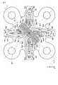
図3を用いて第1実施形態に係る起歪体16の詳細な平面構成について説明する。図3は、起歪体16の歪センサ等が設けられた主表面側から見た中央部161および接続部163を詳細に示す平面図である。Detailed Configuration The detailed planar configuration of the
図3に示すように、接続部163の主表面上には、16個の歪センサ(歪ゲージ)Sa1、Sb1、Sa2、Sb2、Sa3、Sb3、Sa4、Sb4、Sa5、Sb5、Sa6、Sb6、Sa7、Sb7、Sa8、Sb8が設けられる。歪センサSa1〜Sb8は、後述するように金属薄膜抵抗体であって、例えばクロム(Cr)および窒素(N)を含む抵抗体(Cr−N抵抗体)である。そのため、後述するようにパターンニングのみで所望な位置に複数の歪センサSa1〜Sb8を配置できる。また、Cr−N抵抗体は、温度係数が小さいため、温度補償を容易とすることができる。歪センサSa1〜Sb8の長手方向は、対角線L1に沿う方向となるように構成される。 As shown in FIG. 3, 16 strain sensors (strain gauges) Sa1, Sb1, Sa2, Sb2, Sa3, Sb3, Sa4, Sb4, Sa5, Sb5, Sa6, Sb6, are placed on the main surface of the connecting
中央部161の主表面上には、16個の参照抵抗Ra1、Rb1、Ra2、Rb2、Ra3、Rb3、Ra4、Rb4、Ra5、Rb5、Ra6、Rb6、Ra7、Rb7、Ra8、Rb8が設けられる。参照抵抗Ra1〜Rb8の形状は、実質的に歪センサSa1〜Sb8と同一であり、その長手方向は対角線L1に沿う方向となるように構成される。さらに、中央部161の主表面上には、中央部161の対角線L1の方向の一方に沿って電極171が設けられる。 On the main surface of the
歪センサSa1〜Sb8と参照抵抗Ra1〜Rb8とは、後述する8つのブリッジ回路を構成するように、主表面上に設けられた電極171および配線172に電気的に接続される。配線172の線幅は、歪センサSa1〜Sb8と参照抵抗Ra1〜Rb8とを接続する部分においては小さくなるように構成される一方、その他の部分においては配線抵抗を低減するために接続部分に比べて大きくなるように構成される。 The strain sensors Sa1 to Sb8 and the reference resistors Ra1 to Rb8 are electrically connected to
しかも、歪センサSa1〜Sb8、参照抵抗Ra1〜Rb8、電極171、および配線172は、後述する薄膜技術を利用した製造方法を用いて、同一の主表面上に一体的に形成される。そのため、歪センサSa1〜Sb8、参照抵抗Ra1〜Rb8、電極171、および配線172は、起歪体16の対角線L1において鏡像対称となるようにレイアウト構成される。 Moreover, the strain sensors Sa1 to Sb8, the reference resistors Ra1 to Rb8, the
図4を用いて起歪体16の詳細な断面構成について説明する。図4は、図3の歪センサSa1を含む接続部163の断面図である。 The detailed cross-sectional structure of the
図4に示すように、接続部163の主表面上に絶縁膜170が設けられる。絶縁膜170上に感歪膜としてのCr−N抵抗体である歪センサSa1が設けられる。歪センサSa1上に銅(Cu)にて形成された電極リード膜である配線172が設けられる。歪センサSa1上および配線172上を覆うようにオバーガラス(OG)膜175が設けられる。また、配線172と歪センサSa1との界面および配線172とOG膜175との界面には、密着性を高めるためにクロム(Cr)を含む接着膜172aが設けられる。 As shown in FIG. 4, the insulating
尚、この断面では図示していないが、中央部161における配線172の端部には、電極171が設けられる。電極171は、接着膜172a上に順次設けられた銅(Cu)と金(Au)との積層構造により構成される。 Although not shown in this cross section, an
ブリッジ回路
図5を用いて第1実施形態に係る起歪体16のブリッジ回路について説明する。図5は、第1実施形態に係る起歪体16のブリッジ回路を説明するための図表である。Bridge circuit The bridge circuit of the
図5に示すように、起歪体16は、8つのブリッジ回路Ba1、Ba2、Ba3、Ba4、Ba5、Ba6、Ba7、Ba8を含む。 As shown in FIG. 5, the
ブリッジ回路Ba1は、歪センサSa1、Sa2と参照抵抗Ra1、Ra2とを備える。電源端子Eと接地Gとの間に、順次、歪センサSa1および参照抵抗Ra1、並びに参照抵抗Ra2および歪センサSa2が直列接続される。直列接続された歪センサSa1および参照抵抗Ra1と、直列接続された参照抵抗Ra2および歪センサSa2とは、電源端子Eと接地Gとの間で並列接続される。一方の端子V−は、歪センサSa1と参照抵抗Ra1との結線に接続される。他方の端子V+は、参照抵抗Ra2と歪センサSa2との結線に接続される。その他のブリッジ回路Ba2〜Ba4についても、上記ブリッジ回路Ba1と同様である。 The bridge circuit Ba1 includes strain sensors Sa1 and Sa2 and reference resistors Ra1 and Ra2. The strain sensor Sa1 and the reference resistor Ra1, and the reference resistor Ra2 and the strain sensor Sa2 are sequentially connected between the power supply terminal E and the ground G. The strain sensor Sa1 and the reference resistor Ra1 connected in series and the reference resistor Ra2 and the strain sensor Sa2 connected in series are connected in parallel between the power supply terminal E and the ground G. One terminal V- is connected to the connection between the strain sensor Sa1 and the reference resistor Ra1. The other terminal V + is connected to the connection between the reference resistor Ra2 and the strain sensor Sa2. The other bridge circuits Ba2 to Ba4 are the same as those of the bridge circuit Ba1.
ブリッジ回路Bb1は、歪センサSb1、Sb2と参照抵抗Rb1、Rb2とを備える。電源端子Eと接地Gとの間に、順次、歪センサSb1および参照抵抗Rb1、並びに歪センサSb2および参照抵抗Rb2が直列接続される。直列接続された歪センサSb1および参照抵抗Rb1と、直列接続された歪センサSb2および参照抵抗Rb2とは、電源端子Eと接地Gとの間で並列接続される。一方の端子V−は、歪センサSb1と参照抵抗Rb1との結線に接続される。他方の端子V+は、歪センサSb2と参照抵抗Rb2との結線に接続される。その他のブリッジ回路Bb2〜Bb4についても、上記ブリッジ回路Bb1と同様である。 The bridge circuit Bb1 includes strain sensors Sb1 and Sb2 and reference resistors Rb1 and Rb2. The strain sensor Sb1 and the reference resistor Rb1 and the strain sensor Sb2 and the reference resistor Rb2 are sequentially connected in series between the power supply terminal E and the ground G. The strain sensor Sb1 and the reference resistor Rb1 connected in series and the strain sensor Sb2 and the reference resistor Rb2 connected in series are connected in parallel between the power supply terminal E and the ground G. One terminal V- is connected to the connection between the strain sensor Sb1 and the reference resistor Rb1. The other terminal V + is connected to the connection between the strain sensor Sb2 and the reference resistor Rb2. The other bridge circuits Bb2 to Bb4 are the same as those of the bridge circuit Bb1.
上記構成において、外部から力およびトルクが加わると、中央部161の位置が外周部162の位置に比較して相対的に変化するため、接続部163が力およびトルクに応じて変形する。この接続部163の変形に応じ、接続部163に設けられた各歪センサRa1〜Ra8に応力が加わり、各ブリッジ回路Ba1〜Bb4の各端子V−、V+の電圧のバランスが崩れ、力およびトルクに応じた所定の検出信号が検出される。 In the above configuration, when a force and torque are applied from the outside, the position of the
[製造方法]
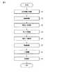
図6を用いて第1実施形態に係る起歪体16の製造方法について説明する。図6は、第1実施形態に係る起歪体16の製造方法を説明するためのフローチャートである。[Production method]
A method for manufacturing the strain-causing
図6に示すように、まず起歪体16の寸法検査等の所定の検査を行った後、起歪体16に対して所定の前処理を行う。前処理としては、例えば検査後の起歪体16の主表面上を、超音波や所定の薬剤等を用いた洗浄処理等が含まれる(B1)。 As shown in FIG. 6, first, a predetermined inspection such as a dimensional inspection of the
続いて、前処理後の起歪体16の主表面上に、例えば熱酸化法等を用いて絶縁膜170を成膜する(B2)。 Subsequently, an insulating
続いて、例えば所定のアニーリング処理等による熱処理を起歪体16に行い、成膜した絶縁膜170の絶縁性等の特性が所定値以上となるように特性出しを行う(B3)。 Subsequently, for example, a heat treatment by a predetermined annealing treatment or the like is performed on the
続いて、絶縁膜170上に、例えば所定のターゲットを用いたスパッタ法等を用いて、クロム(Cr)および窒素(N)を含んだCr−N薄膜を形成する。さらに、形成したCr−N薄膜上にフォトレジストを塗布し、塗布したフォトレジストにパターニングを行う。具体的には、中央部161の参照抵抗Ra1〜Rb8が配置される位置に参照抵抗Ra1〜Rb8と同一の平面形状のパターンをフォトレジストに転写し、接続部163の歪センサSa1〜Sb8が配置される位置に歪センサSa1〜Sb8と同一の平面形状のパターンをフォトレジストに転写し、パターンが転写された部分以外のフォトレジストを除去する。さらに、残存するパターンが転写されたフォトレジストをマスクとして、所定のエッチング処理を絶縁膜170の表面上まで行うことで、中央部161および接続部163の所定の位置に所望の形状の参照抵抗Ra1〜Rb8および歪センサSa1〜Sb8を形成する(B4)。 Subsequently, a Cr—N thin film containing chromium (Cr) and nitrogen (N) is formed on the insulating
続いて、中央部161および接続部163に、例えば上記ステップB4と同様の製造工程等を用いて、密着性を高めるためのクロム(Cr)薄膜による接着膜172aを形成し、当該接着膜172a上に、銅(Cu)を含む所定の電極リード膜を成膜して歪センサSa1〜Sb8および参照抵抗Ra1〜Rb8を電気的に接続するための配線172を形成する。さらに、形成した配線172上に、同様の製造工程によりクロム薄膜による接着膜172aを形成する(B5)。 Subsequently, an
続いて、一方の対角線L1の方向に沿って、中央部161における配線172の端部の接着膜172a上に、例えば上記ステップB4と同様の製造工程等を用いて、銅(Cu)と金(Au)からなる積層構造を順次形成して所定の電極膜を成膜し、電極171を形成する(B6)。 Subsequently, along the direction of one diagonal line L1, copper (Cu) and gold (Cu) and gold (on the
続いて、例えばCVD(Chemical Vapor Deposition)法等を用いて、電極171上を除く起歪体16の主表面上に、OG膜175を形成する(B7)。 Subsequently, for example, by using a CVD (Chemical Vapor Deposition) method or the like, an
続いて、起歪体16の主表面上に形成した歪センサSa1〜Sb8等に対して所定の歪特性検査およびストレス検査等を施し、形成した歪センサSa1〜Sb8等に要求される特性を確認する(B8)。 Subsequently, the strain sensors Sa1 to Sb8 and the like formed on the main surface of the
以上の製造方法により、第1実施形態に係る起歪体16を製造する。 The strain-causing
[作用効果]
以上説明したように、第1実施形態に係る起歪体16は、実質的に歪が生じない中央部161の主要面上に設けられ、複数の歪センサSa1〜Sb8と共にブリッジ回路Ba1〜Bb4を構成する複数の参照抵抗Ra1〜Rb8を備える(図3)。そのため、参照抵抗Ra1〜Rb8は、歪センサSa1〜Sb8と同一の起歪体16の主表面上に一体的に設けられる。その結果、歪センサSa1〜Sb8と参照抵抗Ra1〜Rb8との間に生じる温度誤差および外部ノイズの影響を低減でき、検出精度を向上することができる。[Action effect]
As described above, the
しかも、歪センサSa1〜Sb8、参照抵抗Ra1〜Rb8、電極171、および配線172は、起歪体16の対角線L1において鏡像対称の関係となるように、そのレイアウトが構成される(図3)。そのため、中央部161および接続部163の主表面上の限られたスペースに歪センサSa1〜Sb8等を配置するのに最適な構成となっている。 Moreover, the layout of the strain sensors Sa1 to Sb8, the reference resistors Ra1 to Rb8, the
さらに、ブリッジ回路Ba1〜Bb4を構成するために必要な歪センサSa1〜Sb8、参照抵抗Ra1〜Rb8、電極171、および配線172は、薄膜技術を利用した製造方法により、起歪体16の主要面上のみに設けられる(図4、図6)。そのため、高感度なセンサSa1〜Sb8を高密度かつ高精度に起歪体16の接続部163に設けることができる。従って、検出精度を補うために多数(例えば90個程度)の歪センサを配置する必要がなく、起歪体の表面上だけでなく例えば起歪体の側面上に接着剤等を用いて歪センサを貼り付ける必要もない。例えば本実施形態のような製造方法を用いない場合、歪センサの位置は、所望の位置より数百μm程度の誤差を生じ得るため、特定軸以外の力およびトルクが検出される多軸干渉の影響が増大する。また、例えば参照抵抗を起歪体の外部に設ける場合には温度誤差や外部ノイズが増大するため、温度誤差や外部ノイズを校正する必要もある。しかし、本実施形態では、このような不都合が生じることはない。 Further, the strain sensors Sa1 to Sb8, reference resistors Ra1 to Rb8,
また、Z方向に沿った起歪体16の高さHzは、中央部161、外周部162、および接続部163において実質的に同一である。起歪体16の高さHzは、X方向またはY方向に沿った外周部162の幅W162よりも大きくなるように構成される(Hz>W162)。さらに、外周部162および接続部163の弾性は、中央部163の弾性よりも大きくなるように構成される。外周部162および接続部163は弾性機能を有し、中央部163の弾性機能を有さないように構成されることがより望ましい。上記構成により、XYZ軸の各出力ゲインおよび各剛性をより適正に調整することが可能となる点で有利である。 Further, the height Hz of the
(第2実施形態(起歪体のその他の形状の一例))
図7を用いて第2実施形態に係る起歪体16Aを説明する。図7は、第2実施形態に係る起歪体16Aの平面構造を示す平面図である。第2実施形態は、起歪体のその他の形状の一例に関する。(Second embodiment (an example of another shape of the strain-causing body))
The
図7に示すように、起歪体16Aは、対角線L2の方向における中央部161および外周部の各角部がほぼ直角形状である点で、第1実施形態に係る起歪体16と相違する。歪センサSa1〜Sb8は、同様に結合部163に設けられる。尚、参照抵抗等のその他の構成は、ここでの図示を省略している。 As shown in FIG. 7, the
その他の構造は、上記第1実施形態と実質的に同様であるため、その詳細な説明を省略する。また、動作に関しても、上記第1実施形態と実質的に同様であるため、その詳細な説明を省略する。 Since other structures are substantially the same as those of the first embodiment, detailed description thereof will be omitted. Further, since the operation is substantially the same as that of the first embodiment, detailed description thereof will be omitted.
[作用効果]
第2実施形態に係る起歪体16Aの構造および動作によれば、少なくとも第1実施形態と同様の作用効果が得られる。また、必要に応じて、第2実施形態に係る起歪体16Aを適用することが可能である。[Action effect]
According to the structure and operation of the
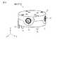
(第3実施形態(3ビーム方式の起歪体の一例))
図8および図9を用いて第3実施形態に係る起歪体16Bを説明する。図8は、第3実施形態に係る起歪体16Bの全体構成を示す斜視図である。図9は、図8の起歪体16Bの平面構造を示す平面図である。第3実施形態は、3ビーム方式の起歪体の一例に関する。(Third embodiment (an example of a three-beam type strain-causing body))
The
図8および図9に示すように、起歪体16Bは、第1実施形態に係る起歪体16と比較して、ビーム部である接続部163が3つの3ビーム方式として構成されている。そのため、接続部163には、12個の歪センサSa1〜Sb6が設けられる点で、上記第1実施形態と相違する。従って、ここでの図示は省略しているが、歪センサSa1〜Sb6に対応する中央部161に設けられる参照抵抗も12個である。 As shown in FIGS. 8 and 9, in the
外周部161の平面形状は、3本の対角線L3の方向に設けられる3つの角部を頂点とする三角形状である。また、外周部161の角部は、対角線L3を半径とする円に接し、ネジ穴17aの円形状と同心の円形状となるように構成される。 The planar shape of the outer
その他の構造および動作は、上記第1実施形態と実質的に同様であるため、その詳細な説明を省略する。 Since other structures and operations are substantially the same as those of the first embodiment, detailed description thereof will be omitted.
[作用効果]
第3実施形態に係る起歪体16Bの構造および動作によれば、少なくとも第1実施形態と同様の作用効果が得られる。[Action effect]
According to the structure and operation of the
さらに、第3実施形態に係る起歪体16Bは、ビーム部である接続部163が3つである3ビーム方式として構成されるため、接続部163には12個の歪センサSa1〜Sb6が設けられ、中央部161には12個の参照抵抗が設けられる(図8、図9)。 Further, since the
このように、第3実施形態に係る起歪体16Bは、4つの接続部163が設けられる4ビーム方式の起歪体16、16Aと比較して、1セットの歪センサおよび参照抵抗、並びにこれに伴う配線や電極を低減することができる。そのため、起歪体16Bの大きさを縮小化できる点で有利である。さらに、冗長な1セットの歪センサおよび参照抵抗が不要となるため、最小数のブリッジ回路構成にて6軸方向の力およびトルクを検出でき、製造コストも低減できる点で有利である。 As described above, the
(第4実施形態(力覚センサに適用した一例))
図10乃至図12を用いて第4実施形態を説明する。第4実施形態は、第1実施形態に係る起歪体16を力覚センサに適用した一例に関する。第4実施形態に係る力覚センサは、例えばロボットアーム等に用いられ、XYZ方向の力およびトルクを検出するための6軸力覚センサである。(Fourth embodiment (an example applied to a force sensor))
The fourth embodiment will be described with reference to FIGS. 10 to 12. The fourth embodiment relates to an example in which the
[構成]
図10は、第1実施形態に係る起歪体16を備えた力覚センサ10の外観を示す斜視図である。図11は、図10の力覚センサ10を示す分解斜視図である。[Constitution]
FIG. 10 is a perspective view showing the appearance of the force sensor 10 including the strain-causing
図10および図11に示すように、力覚センサ10は、円筒状の本体11と、本体11に対して動作可能な円筒状の可動体12とを備える。本体11は、本体11の底部に形成された複数のネジ穴19aを貫通する複数の取付ネジ19により、図示せぬロボットアームの本体に固定される。可動体12は、その上面に図示せぬロボットアームのハンド部分を取り付けるためのハンド取付プレートとして機能する。 As shown in FIGS. 10 and 11, the force sensor 10 includes a cylindrical
本体(ベース)11は、力覚センサ10の本体となるベース部材であり、可動体12は、弾性変形が可能な起歪体16を介在して本体11に対して、6軸方向(X軸方向、Y軸方向、Z軸方向、及び各軸周り方向)に動作可能に取着されている。 The main body (base) 11 is a base member serving as the main body of the force sensor 10, and the
すなわち、図11に示すように、起歪体16の中央部161は、複数のネジ穴18aをそれぞれ貫通するハンドプレート固定ネジ18により可動体(第1支持部材)12に固定される。起歪体16の外周部162は、複数のネジ穴17aをそれぞれ貫通する起歪体固定ネジ17により、本体11(第2支持部材)に固定される。 That is, as shown in FIG. 11, the
起歪体16の主表面および裏面は、X軸、Y軸により形成される面と平行に配置され、起歪体16の中心Oを垂直に通る線は、Z軸と一致されている。上記構成において、可動体12に外力が加えられると、可動体12が動作し、起歪体16の接続部163が変形する。上記のように、起歪体16の接続部163には歪センサSa1〜Sb8が設けられているため、歪センサSa1〜Sb8により起歪体16の変形が電気信号として検出される。 The main front surface and the back surface of the
可動体12の周面には、例えば4つの円形の開口部13が等間隔に設けられている。すなわち、各開口部13は、X軸方向とY軸方向に配置されている。開口部13の数は、4つに限定されず、3つ以上であればよい。各開口部13の内部にはストッパ14が配置され、各ストッパ14は、ストッパ取付ボルト15により、本体11に固定されている。 For example, four
ストッパ14は、可動体12の動作範囲を規制するものであり、ストッパ14の最外周部には、開口部13の内面が当接可能な第1側面14aを備えている。すなわち、第1側面14aは、可動体12の動作に伴って起歪体16が変形した際、可動体12の開口部13の内面が第1側面14aに当接し、起歪体16の接続部163の過剰な変形を防止する保護機構として機能する。 The
本体11の内部には、起歪体16に対向して基板20が設けられる。基板20は、複数のねじ穴21aを有し、各ネジ穴21aを貫通する固定ネジ21により、本体11に固定される。基板20には、起歪体16に設けられた歪センサが電気的に接続される。この詳細については後述する。 A
本体11の底部には、開口部11aを閉塞するカバー22が装着される。すなわち、カバー22は、複数のねじ穴23aを有し、これらネジ穴23aを貫通する固定ネジ23により、本体11に固定される。 A
本体11の側面には、検出信号を外部に伝達するための配線25が引き出されている。配線25は、基板20と電気的に接続されている。 A
力覚センサに実装される状態の起歪体
図12を用いて力覚センサ10に実装される状態の起歪体16について詳細に説明する。図12は、力覚センサ10に実装される状態の起歪体16を示す断面図である。The strain-causing
図12に示すように、起歪体16の主表面上に、絶縁膜170が設けられ、絶縁膜170上に電極171が設けられる。さらに、力覚センサ10に実装するために、電極171上に異方性導電フィルム(ACF:Anisotropic Conductive Film)181が設けられる。異方性導電フィルム181上に、電極171と基板20とを電気的に接続するためのリード配線182が設けられる。リード配線182は、ここでは、絶縁性の柔軟なフィルムと当該フィルムに配線された所定の電気回路とを備えており、可動体12の動きに合わせて自在に曲がることが可能な構成なFPC(Flexible printed circuits)である。また、起歪体16の主表面上を覆うように、保護シール183が設けられる。 As shown in FIG. 12, an insulating
[検出動作]
上記構成の力覚センサ10の検出動作について簡単に説明する。ここでは、Z軸方向において可動体12のほぼ中央部分に加えられた外力(荷重)を検出する場合を一例に挙げる。[Detection operation]
The detection operation of the force sensor 10 having the above configuration will be briefly described. Here, a case where an external force (load) applied to a substantially central portion of the
Z軸方向において可動体12のほぼ中央部分に外力が加えられると、外力によって可動体12がZ軸方向に沿って下方に移動する。本体11は固定されており外力によっても移動しないため、可動体12は、開口部13の上側の内面がストッパ14の上側の第1側面14aに当接するまで、下方に移動する。 When an external force is applied to a substantially central portion of the
そのため、可動体12の下面が起歪体16の上面を加圧し、加圧された起歪体16の接続部163は変形を起こす。ストッパ14により、起歪体16の変形は所定の範囲に限定されているため、過剰な外力による破壊から起歪体16が保護される。起歪体16の変形は、上述した歪センサSa1〜Sb8により検出され、ブリッジ回路Ba1〜Bb4により電気信号に変換される。検出された電気信号は、電極171からリード配線182および基板20を介して配線25により外部に伝達され、外力を検出することができる。 Therefore, the lower surface of the
その後、可動体12への外力の印加が解除されると、起歪体16の接続部163は、弾性変形により、元の形状に復帰する。 After that, when the application of the external force to the
尚、ここでは、Z軸方向における外力検出動作を一例に挙げたが、X軸方向およびY軸方向におけるその他の外力検出動作も同様である。また、X、Y、Z軸方向における各トルク検出動作についても、上記外力検出動作と実質的に同様であるため、詳細な説明を省略する。 Although the external force detection operation in the Z-axis direction is given as an example here, the same applies to other external force detection operations in the X-axis direction and the Y-axis direction. Further, since each torque detection operation in the X, Y, and Z axis directions is substantially the same as the external force detection operation, detailed description thereof will be omitted.
[作用効果]
第4実施形態に係る起歪体16を備えた力覚センサ10の構造および動作によれば、少なくとも第1実施形態と同様の作用効果が得られる。[Action effect]
According to the structure and operation of the force sensor 10 provided with the strain-causing
さらに、必要に応じて、本実施形態の起歪体16を力覚センサ10に適用することが可能である。 Further, if necessary, the strain-causing
また、力覚センサ10は、可動体12の動作範囲を規制するものであり、その最外周部に開口部13の内面と当接可能な第1側面14aを有するストッパ14を備える。このように、ストッパ14は、非常にシンプルな形状であり、かつ6軸方向の全てに対して保護機能を有している。その結果、高感度かつ製造コストの低減化に有利な力覚センサ10を提供することが可能となる。 Further, the force sensor 10 regulates the operating range of the
(変形例)
以上、第1乃至第4実施形態を一例に挙げて説明したが、本発明の実施形態は、上記第1乃至第3実施形態に係る起歪体16、16A、16Bに限定されるものではなく、必要に応じて種々の変形が可能であることは勿論である。(Modification example)
Although the first to fourth embodiments have been described above as an example, the embodiments of the present invention are not limited to the strain-causing
さらに、起歪体16、16A、16Bが適用可能な対象は、第4実施形態において説明した力覚センサ10に限定されず、各種のセンサに適用可能であることは勿論である。 Further, the object to which the
その他、本発明は上記各実施形態そのままに限定されるものではなく、実施段階ではその要旨を逸脱しない範囲で構成要素を変形して具体化できる。また、上記各実施形態に開示されている複数の構成要素の適宜な組み合わせにより、種々の発明を形成できる。例えば、実施形態に示される全構成要素から幾つかの構成要素を削除してもよい。さらに、異なる実施形態にわたる構成要素を適宜組み合わせてもよい。 In addition, the present invention is not limited to each of the above embodiments as it is, and at the implementation stage, the components can be modified and embodied within a range that does not deviate from the gist thereof. In addition, various inventions can be formed by appropriately combining the plurality of components disclosed in each of the above embodiments. For example, some components may be removed from all the components shown in the embodiments. In addition, components across different embodiments may be combined as appropriate.
10…力覚センサ、11…本体、12…可動体、16、16A、16B…起歪体、161…中央部、162…外周部、163…接続部(ビーム部)、171…電極、172…配線、Sa1〜Sb8…歪センサ、Ra1〜Rb8…参照抵抗、Ba1〜Bb4…ブリッジ回路。 10 ... Force sensor, 11 ... Main body, 12 ... Movable body, 16, 16A, 16B ... Distortion body, 161 ... Central part, 162 ... Outer peripheral part, 163 ... Connection part (beam part), 171 ... Electrode, 172 ... Wiring, Sa1 to Sb8 ... Distortion sensor, Ra1 to Rb8 ... Reference resistance, Ba1 to Bb4 ... Bridge circuit.
Claims (8)
Translated fromJapanese前記中央部の周囲を囲む外周部と、
前記中央部と前記外周部とを接続する複数の接続部と、
前記接続部の主表面上に設けられる複数の歪センサと、
前記中央部の主表面上に設けられ、前記複数の歪センサと共にブリッジ回路を構成する複数の参照抵抗と、を具備し、
前記中央部は、外部の第1支持部材に接続され、
前記外周部は、外部の第2支持部材に接続され、
前記外周部および前記接続部の弾性は、前記中央部の弾性よりも大きい
起歪体。Central part and
An outer peripheral portion that surrounds the central portion and
A plurality of connecting portions connecting the central portion and the outer peripheral portion,
A plurality of strain sensors provided on the main surface of the connection portion, and
A plurality of reference resistors provided on the main surface of the central portion and forming a bridge circuit together with the plurality of strain sensors are provided.
The central portion is connected to an external first support member.
The outer peripheral portion is connected to an external second support member, and the outer peripheral portion is connected to an external second support member.
A strain-causing body in whichthe elasticity of the outer peripheral portion and the connection portion is larger than the elasticity of the central portion.
前記中央部および前記接続部の主表面上に設けられ、前記複数の歪センサ、前記複数の参照抵抗、および前記電極を電気的に接続する配線と、を更に具備するFurther provided on the main surface of the central portion and the connecting portion, the plurality of strain sensors, the plurality of reference resistors, and wiring for electrically connecting the electrodes are provided.
請求項1に記載の起歪体。The strain-causing body according to claim 1.
請求項2に記載の起歪体。The strain-causing body according to claim 2.
請求項3に記載の起歪体。The strain-causing body according to claim 3.
請求項2乃至4のいずれかに記載の起歪体。The strain-causing body according to any one of claims 2 to 4.
円筒状の本体と、Cylindrical body and
前記本体に対して動作可能な円筒状の可動体と、を具備し、A cylindrical movable body that can operate with respect to the main body is provided.
前記起歪体の前記中央部は、支持部材である前記本体または前記可動体の一方に接続され、The central portion of the strain-causing body is connected to one of the main body or the movable body which is a support member.
前記起歪体の前記外周部は、支持部材である前記本体または前記可動体の他方に接続されるThe outer peripheral portion of the strain-causing body is connected to the main body, which is a support member, or the other of the movable body.
力覚センサ。Force sensor.
請求項6に記載の力覚センサ。The force sensor according to claim 6.
前記開口部のそれぞれの内部に配置され、前記開口部の直径より小さな第1外径を有する第1側面を備えるストッパと、A stopper arranged inside each of the openings and having a first side surface having a first outer diameter smaller than the diameter of the opening.
前記ストッパを前記本体に固定する固定部材と、を更に具備するFurther provided with a fixing member for fixing the stopper to the main body.
請求項6または7に記載の力覚センサ。The force sensor according to claim 6 or 7.
Priority Applications (5)
| Application Number | Priority Date | Filing Date | Title |
|---|---|---|---|
| JP2016239668AJP6869710B2 (en) | 2016-12-09 | 2016-12-09 | A strain-causing body and a force sensor equipped with the strain-causing body |
| EP17878908.7AEP3553487A1 (en) | 2016-12-09 | 2017-09-29 | Strain generation body and force sensor equipped with strain generation body |
| CN201780060145.2ACN109791083A (en) | 2016-12-09 | 2017-09-29 | Response body and force snesor with the response body |
| PCT/JP2017/035637WO2018105211A1 (en) | 2016-12-09 | 2017-09-29 | Strain generation body and force sensor equipped with strain generation body |
| US16/374,068US11085842B2 (en) | 2016-12-09 | 2019-04-03 | Strain generation body and force sensor equipped with strain generation body |
Applications Claiming Priority (1)
| Application Number | Priority Date | Filing Date | Title |
|---|---|---|---|
| JP2016239668AJP6869710B2 (en) | 2016-12-09 | 2016-12-09 | A strain-causing body and a force sensor equipped with the strain-causing body |
Publications (2)
| Publication Number | Publication Date |
|---|---|
| JP2018096757A JP2018096757A (en) | 2018-06-21 |
| JP6869710B2true JP6869710B2 (en) | 2021-05-12 |
Family
ID=62491436
Family Applications (1)
| Application Number | Title | Priority Date | Filing Date |
|---|---|---|---|
| JP2016239668AActiveJP6869710B2 (en) | 2016-12-09 | 2016-12-09 | A strain-causing body and a force sensor equipped with the strain-causing body |
Country Status (5)
| Country | Link |
|---|---|
| US (1) | US11085842B2 (en) |
| EP (1) | EP3553487A1 (en) |
| JP (1) | JP6869710B2 (en) |
| CN (1) | CN109791083A (en) |
| WO (1) | WO2018105211A1 (en) |
Families Citing this family (15)
| Publication number | Priority date | Publication date | Assignee | Title |
|---|---|---|---|---|
| JP6794293B2 (en)* | 2017-02-24 | 2020-12-02 | 日本電産コパル電子株式会社 | A strain-causing body and a force sensor equipped with the strain-causing body |
| JP6776152B2 (en) | 2017-02-24 | 2020-10-28 | 日本電産コパル電子株式会社 | A strain-causing body and a force sensor equipped with the strain-causing body |
| JP6789853B2 (en)* | 2017-03-08 | 2020-11-25 | 日本電産コパル電子株式会社 | Force sensor |
| JP2020012657A (en)* | 2018-07-13 | 2020-01-23 | 日本電産コパル電子株式会社 | Torque sensor |
| JP7059138B2 (en) | 2018-07-13 | 2022-04-25 | 日本電産コパル電子株式会社 | Torque sensor mounting structure |
| EP3822604A4 (en) | 2018-07-13 | 2022-05-18 | Nidec Copal Electronics Corporation | MOUNTING STRUCTURE OF A TORQUE SENSOR |
| CN108955969B (en)* | 2018-08-31 | 2021-03-02 | 纳恩博(北京)科技有限公司 | Resistance strain gauge, induction component, force sensor and slide |
| JP7184699B2 (en)* | 2019-03-29 | 2022-12-06 | 株式会社レプトリノ | force sensor |
| WO2021035742A1 (en)* | 2019-08-30 | 2021-03-04 | 深圳纽迪瑞科技开发有限公司 | Pressure sensing assembly, pressure sensing method and device |
| US11846557B2 (en)* | 2020-05-29 | 2023-12-19 | Bota Systems AG | Torque and force transducer |
| CN111780661B (en)* | 2020-07-22 | 2021-10-08 | 华中科技大学 | An accurate measurement method and system for bending strain of flexible electronic devices |
| JP7592957B2 (en)* | 2020-12-24 | 2024-12-03 | ミネベアミツミ株式会社 | Sensor chip, force sensor device |
| JP7618916B2 (en)* | 2020-12-24 | 2025-01-22 | ミネベアミツミ株式会社 | Strain-generating body, force sensor device |
| CN115112286A (en)* | 2021-03-19 | 2022-09-27 | 美蓓亚三美株式会社 | Strain body and force sensor device |
| JP2023114132A (en)* | 2022-02-04 | 2023-08-17 | ニデックドライブテクノロジー株式会社 | Annular body, wave speed reducer, and robot |
Family Cites Families (17)
| Publication number | Priority date | Publication date | Assignee | Title |
|---|---|---|---|---|
| JPS60221288A (en)* | 1984-04-13 | 1985-11-05 | 株式会社 富士電機総合研究所 | Pressure recognition control device |
| US4771638A (en)* | 1985-09-30 | 1988-09-20 | Kabushiki Kaisha Toyota Chuo Kenkyusho | Semiconductor pressure sensor |
| JPH0643937B2 (en)* | 1987-09-11 | 1994-06-08 | 日立建機株式会社 | Load detector |
| JP2004239621A (en)* | 2003-02-03 | 2004-08-26 | Japan Science & Technology Agency | 3D pressure sensor |
| JP4303091B2 (en)* | 2003-11-10 | 2009-07-29 | ニッタ株式会社 | Strain gauge type sensor and strain gauge type sensor unit using the same |
| US7430920B2 (en)* | 2005-12-16 | 2008-10-07 | Hitachi, Ltd. | Apparatus for measuring a mechanical quantity |
| US6886415B1 (en)* | 2004-08-03 | 2005-05-03 | Toshiba Electric Engineering Corporation | Tactile sensor and gripping robot using the same |
| US20060185446A1 (en)* | 2005-02-18 | 2006-08-24 | Speckhart Frank H | Printed strain gage for vehicle seats |
| FR2883372B1 (en)* | 2005-03-17 | 2007-06-29 | Commissariat Energie Atomique | FORCE MEASURING DEVICE BY RESISTIVE DETECTION WITH DOUBLE BRIDGE OF WHEASTONE |
| JP4203051B2 (en)* | 2005-06-28 | 2008-12-24 | 本田技研工業株式会社 | Force sensor |
| JP5007083B2 (en)* | 2006-08-08 | 2012-08-22 | 本田技研工業株式会社 | Force sensor chip |
| JP5817371B2 (en) | 2011-09-15 | 2015-11-18 | トヨタ自動車株式会社 | Torque measuring device |
| DE102012210021A1 (en)* | 2012-06-14 | 2013-12-19 | Tecsis Gmbh | Force sensor with a sensor plate with local differences in stiffness |
| JP6135408B2 (en) | 2013-09-04 | 2017-05-31 | トヨタ自動車株式会社 | Torque sensor, driving device, and robot |
| CN205451003U (en)* | 2015-12-18 | 2016-08-10 | 金龙机电(东莞)有限公司 | A pressure sensitive touch screen |
| JP6808469B2 (en)* | 2016-12-07 | 2021-01-06 | 日本電産コパル電子株式会社 | Torque sensor |
| JP6776152B2 (en)* | 2017-02-24 | 2020-10-28 | 日本電産コパル電子株式会社 | A strain-causing body and a force sensor equipped with the strain-causing body |
- 2016
- 2016-12-09JPJP2016239668Apatent/JP6869710B2/enactiveActive
- 2017
- 2017-09-29WOPCT/JP2017/035637patent/WO2018105211A1/ennot_activeCeased
- 2017-09-29CNCN201780060145.2Apatent/CN109791083A/enactivePending
- 2017-09-29EPEP17878908.7Apatent/EP3553487A1/ennot_activeWithdrawn
- 2019
- 2019-04-03USUS16/374,068patent/US11085842B2/enactiveActive
Also Published As
| Publication number | Publication date |
|---|---|
| JP2018096757A (en) | 2018-06-21 |
| CN109791083A (en) | 2019-05-21 |
| EP3553487A1 (en) | 2019-10-16 |
| WO2018105211A1 (en) | 2018-06-14 |
| US20190226929A1 (en) | 2019-07-25 |
| US11085842B2 (en) | 2021-08-10 |
Similar Documents
| Publication | Publication Date | Title |
|---|---|---|
| JP6869710B2 (en) | A strain-causing body and a force sensor equipped with the strain-causing body | |
| JP6615365B2 (en) | Force / torque sensor and method | |
| JP6776152B2 (en) | A strain-causing body and a force sensor equipped with the strain-causing body | |
| US11187598B2 (en) | Strain body and force sensor provided with the strain body | |
| JP6611762B2 (en) | Strain gauge and multi-axis force sensor | |
| US20190376855A1 (en) | Strain body and force sensor provided with the strain body | |
| JP6817875B2 (en) | Force sensor | |
| JP6611761B2 (en) | Strain gauge and multi-axis force sensor | |
| JP2020134451A (en) | Pressure sensor | |
| JPS6321530A (en) | Force detector | |
| JP6767559B2 (en) | Strain gauge and multi-axial force sensor | |
| JP6836641B2 (en) | Strain gauge and 3-axis force sensor | |
| JP7073471B2 (en) | Distorted body | |
| JP7228465B2 (en) | semiconductor equipment | |
| KR20230017187A (en) | force and torque transducers | |
| JP4399545B2 (en) | Tactile sensor and multi-point tactile sensor | |
| JP6837113B2 (en) | Strain gauge and multi-axial force sensor | |
| JP2020051829A (en) | Load transducer | |
| JP2019045207A (en) | Pressure sensor |
Legal Events
| Date | Code | Title | Description |
|---|---|---|---|
| A621 | Written request for application examination | Free format text:JAPANESE INTERMEDIATE CODE: A621 Effective date:20191107 | |
| A131 | Notification of reasons for refusal | Free format text:JAPANESE INTERMEDIATE CODE: A131 Effective date:20201013 | |
| A521 | Request for written amendment filed | Free format text:JAPANESE INTERMEDIATE CODE: A523 Effective date:20201119 | |
| TRDD | Decision of grant or rejection written | ||
| A01 | Written decision to grant a patent or to grant a registration (utility model) | Free format text:JAPANESE INTERMEDIATE CODE: A01 Effective date:20210406 | |
| A61 | First payment of annual fees (during grant procedure) | Free format text:JAPANESE INTERMEDIATE CODE: A61 Effective date:20210414 | |
| R150 | Certificate of patent or registration of utility model | Ref document number:6869710 Country of ref document:JP Free format text:JAPANESE INTERMEDIATE CODE: R150 | |
| R250 | Receipt of annual fees | Free format text:JAPANESE INTERMEDIATE CODE: R250 | |
| R250 | Receipt of annual fees | Free format text:JAPANESE INTERMEDIATE CODE: R250 |