JP6868544B2 - Autonomous movement method and autonomous movement device - Google Patents
Autonomous movement method and autonomous movement deviceDownload PDFInfo
- Publication number
- JP6868544B2 JP6868544B2JP2017242848AJP2017242848AJP6868544B2JP 6868544 B2JP6868544 B2JP 6868544B2JP 2017242848 AJP2017242848 AJP 2017242848AJP 2017242848 AJP2017242848 AJP 2017242848AJP 6868544 B2JP6868544 B2JP 6868544B2
- Authority
- JP
- Japan
- Prior art keywords
- robot
- intersection
- laser light
- camera
- autonomous movement
- Prior art date
- Legal status (The legal status is an assumption and is not a legal conclusion. Google has not performed a legal analysis and makes no representation as to the accuracy of the status listed.)
- Active
Links
Images


Landscapes
- Manipulator (AREA)
- Control Of Position, Course, Altitude, Or Attitude Of Moving Bodies (AREA)
- Conveying And Assembling Of Building Elements In Situ (AREA)
Description
Translated fromJapanese本発明は、ロボットを自律的に移動させる自律移動方法及び自律移動装置に関する。 The present invention relates to an autonomous movement method and an autonomous movement device for autonomously moving a robot.
特開2012−37288号公報には、位置決め対象物を目標位置に向けて移動させる墨出しシステムが記載されている。墨出しシステムは、自律走行型の墨出し装置、レーザーレンジファインダ、トータルステーション、及び墨出し装置を制御するパーソナルコンピュータを備える。墨出し装置は、多方向移動ホイールを有する走行機構と、杭芯の打設位置を示すマークを地面に押印するスタンプ機構と、スタンプ機構を位置調整可能に支持する位置調整機構と、スタンプ機構及び位置調整機構の上方に設けられた一対の計測プリズムとを備える。スタンプ機構は、押印を行うスタンプ部と、スタンプ部を地面に対して昇降させる昇降機構とを備える。また、一対の計測プリズムは、トータルステーションから投射された測距測角用の光を反射する。 Japanese Unexamined Patent Publication No. 2012-37288 describes an marking system for moving a positioning object toward a target position. The marking system includes an autonomous traveling type marking device, a laser range finder, a total station, and a personal computer that controls the marking device. The marking device includes a traveling mechanism having a multi-directional moving wheel, a stamping mechanism for imprinting a mark indicating a pile core driving position on the ground, a position adjusting mechanism for supporting the stamping mechanism in a position-adjustable manner, a stamping mechanism, and a stamping mechanism. It is provided with a pair of measuring prisms provided above the position adjusting mechanism. The stamp mechanism includes a stamp portion for stamping and an elevating mechanism for raising and lowering the stamp portion with respect to the ground. In addition, the pair of measurement prisms reflect the light for distance measurement and angle measurement projected from the total station.
墨出しシステムでは、レーザーレンジファインダによって墨出し装置の位置を計測しながら、計測された位置に基づいて墨出し装置を目標位置に向けて走行させる。その後、トータルステーションが計測プリズムの位置を算出することによって墨出し装置の位置を計測し、計測された位置と目標位置との誤差を位置調整機構が補正する。そして、スタンプ機構がマークを地面に押印して現場における墨出しを行う。 In the marking system, the position of the marking device is measured by a laser range finder, and the marking device is moved toward a target position based on the measured position. After that, the total station measures the position of the marking device by calculating the position of the measuring prism, and the position adjusting mechanism corrects the error between the measured position and the target position. Then, the stamp mechanism stamps the mark on the ground to perform marking on the site.
前述した墨出しシステムは、スタンプ機構と一対の計測プリズムとを一体として備えており、一対の計測プリズムはスタンプ機構の上方に設けられる。従って、一対の計測プリズムとスタンプ機構との間に機械的誤差が生じるため、位置の認識の精度において改善の余地がある。また、走行機構は多方向移動ホイールによって地面上を移動し、スタンプ機構は昇降機構によってスタンプ部を地面に下降させて押印を行う。よって、段差又は障害物が存在して地面が平坦でない場合には、走行機構による移動、及びスタンプ機構による押印を効率よく行うことができないので、押印等の作業性において改善の余地がある。 The marking system described above includes a stamping mechanism and a pair of measuring prisms as a unit, and the pair of measuring prisms is provided above the stamping mechanism. Therefore, since a mechanical error occurs between the pair of measuring prisms and the stamp mechanism, there is room for improvement in the accuracy of position recognition. Further, the traveling mechanism moves on the ground by a multi-directional moving wheel, and the stamp mechanism lowers the stamp portion to the ground by an elevating mechanism to perform stamping. Therefore, when the ground is not flat due to the presence of steps or obstacles, the movement by the traveling mechanism and the stamping by the stamping mechanism cannot be performed efficiently, so that there is room for improvement in workability such as stamping.
本発明は、位置の認識の精度を高めることができると共に、作業を効率よく行うことができるロボットの自律移動方法及び自律移動装置を提供することを目的とする。 An object of the present invention is to provide a robot autonomous movement method and an autonomous movement device capable of improving the accuracy of position recognition and efficiently performing work.
本発明に係る自律移動方法は、ロボットを自律的に移動させる自律移動方法であって、複数のレーザ光照射装置のそれぞれからレーザ光を照射してレーザ光の交点を表示する工程と、ロボットのカメラが交点を撮影することによってロボットが自己の位置及び向きを認識する工程と、認識した位置及び向きを基に交点に向かってロボットが移動する工程と、を備える。 The autonomous movement method according to the present invention is an autonomous movement method for autonomously moving a robot, in which a step of irradiating laser light from each of a plurality of laser light irradiation devices to display the intersection of the laser light and a robot The robot includes a step of recognizing its own position and orientation by taking a picture of the intersection, and a step of moving the robot toward the intersection based on the recognized position and orientation.
この自律移動方法は、複数のレーザ光照射装置のそれぞれからレーザ光を照射し、複数のレーザ光が交差して形成されるレーザ光の交点を表示する。ロボットは、複数のレーザ光照射装置によって表示された交点を撮影するカメラを備え、カメラによって撮影された交点から自己の位置及び向きを認識する。このように、ロボットは、レーザ光の交点から自己の位置及び向きを認識し、認識した位置及び向きに基づいて交点に向かって移動する。よって、レーザ光の交点を利用することによってロボットの位置及び向きの認識の精度を高めることができる。すなわち、ロボットはレーザ光照射装置とは別体とされており、ロボットとレーザ光照射装置との間に機械的誤差は生じないので、位置及び向きの認識の精度を高めることができる。また、レーザ光の交点は、地面だけでなく壁、天井及び段差にも表示可能であり、ロボットを壁、天井又は段差の近くに移動させてロボットに作業をさせることができるので、ロボットによる作業を効率よく行うことができる。 In this autonomous movement method, laser light is irradiated from each of a plurality of laser light irradiation devices, and the intersection of the laser light formed by intersecting the plurality of laser light is displayed. The robot is provided with a camera that captures the intersections displayed by a plurality of laser light irradiation devices, and recognizes its own position and orientation from the intersections captured by the cameras. In this way, the robot recognizes its own position and direction from the intersection of the laser beams, and moves toward the intersection based on the recognized position and direction. Therefore, the accuracy of recognizing the position and orientation of the robot can be improved by using the intersection of the laser beams. That is, since the robot is separate from the laser light irradiating device and no mechanical error occurs between the robot and the laser light irradiating device, the accuracy of position and orientation recognition can be improved. Further, the intersection of the laser beams can be displayed not only on the ground but also on the wall, ceiling and step, and the robot can be moved near the wall, ceiling or step to allow the robot to work. Can be done efficiently.
本発明に係る自律移動装置は、複数のレーザ光照射装置と、複数のレーザ光照射装置のそれぞれから照射されたレーザ光の交点を撮影するカメラを有するロボットと、を備え、ロボットは、カメラによって撮影された交点から自己の位置及び向きを認識し、認識した位置及び向きを基に交点に向かって移動する。 The autonomous moving device according to the present invention includes a plurality of laser light irradiating devices and a robot having a camera that captures an intersection of laser light radiated from each of the plurality of laser light irradiating devices. It recognizes its own position and orientation from the photographed intersection, and moves toward the intersection based on the recognized position and orientation.
この自律移動装置は、レーザ光を照射する複数のレーザ光照射装置とロボットとを備え、複数のレーザ光照射装置は、各レーザ光が交差するレーザ光の交点を表示する。ロボットは、レーザ光の交点を撮影するカメラを備え、撮影された交点から自己の位置及び向きを認識する。よって、ロボットはレーザ光の交点から認識した位置及び向きに基づいて交点に向かって移動するので、ロボットの位置及び向きの認識の精度を高めることができる。すなわち、前述と同様、ロボットはレーザ光照射装置とは別体とされておりロボットとレーザ光照射装置との間に機械的誤差は生じないので、位置及び向きの精度を高めることができる。また、ロボットを壁、天井又は段差の近くに移動させて壁、天井又は段差の近くでロボットに作業をさせることができるので、ロボットによる作業を効率よく行うことができる。 This autonomous moving device includes a plurality of laser light irradiating devices for irradiating laser light and a robot, and the plurality of laser light irradiating devices display the intersections of the laser light at which the laser light intersects. The robot is equipped with a camera that captures the intersection of laser beams, and recognizes its own position and orientation from the captured intersection. Therefore, since the robot moves toward the intersection based on the position and direction recognized from the intersection of the laser beams, the accuracy of recognizing the position and direction of the robot can be improved. That is, as described above, since the robot is separated from the laser light irradiation device and no mechanical error occurs between the robot and the laser light irradiation device, the accuracy of the position and orientation can be improved. Further, since the robot can be moved near the wall, the ceiling or the step to cause the robot to work near the wall, the ceiling or the step, the work by the robot can be efficiently performed.
また、ロボットは、カメラを移動自在に保持するアームを備えていてもよい。この場合、ロボットは、アームを自在に動かすことによってカメラを任意の位置に効率よく移動させることができる。従って、ロボットの作業性を更に高めることができる。 Further, the robot may be provided with an arm for holding the camera so as to be movable. In this case, the robot can efficiently move the camera to an arbitrary position by freely moving the arm. Therefore, the workability of the robot can be further improved.
本発明によれば、位置の認識の精度を高めることができると共に、作業を効率よく行うことができる。 According to the present invention, the accuracy of position recognition can be improved and the work can be performed efficiently.
以下では、図面を参照しながら本発明に係る自律移動方法及び自律移動装置の実施形態について詳細に説明する。図面において同一又は相当する要素には同一の符号を付し、重複する説明を適宜省略する。また、図面は、理解を容易にするため一部を簡略化又は誇張して描いており、寸法比率等は図面に記載したものに限定されない。 Hereinafter, the autonomous movement method and the embodiment of the autonomous movement device according to the present invention will be described in detail with reference to the drawings. In the drawings, the same or corresponding elements are designated by the same reference numerals, and duplicate description will be omitted as appropriate. In addition, the drawings are partially simplified or exaggerated to facilitate understanding, and the dimensional ratios and the like are not limited to those described in the drawings.
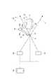
まず、実施形態に係る自律移動装置1について説明する。図1に示されるように、自律移動装置1は、建設現場Aの作業において用いられる。例えば、自律移動装置1は、ロボット10を自律的に移動させることにより、施工の基準となる点又は線を建設現場Aの床、壁又は天井に描写する墨出しを自動的に行う。自律移動装置1は、墨出しを行う自走式の墨出しロボットであるロボット10と、レーザ光Lを照射する複数のレーザ光照射装置20と、座標指定装置30とを備える。 First, the autonomous mobile device 1 according to the embodiment will be described. As shown in FIG. 1, the autonomous mobile device 1 is used in the work of the construction site A. For example, the autonomous moving device 1 automatically moves the
ロボット10は、例えば、本体11と、本体11の下部に設けられて本体11を建設現場Aにおいて移動させる複数の車輪12と、建設現場Aを撮影する周辺検知カメラ13と、本体11から延び出すと共に本体11に対して3次元方向に移動自在とされたアーム15とを備える。アーム15は、レーザ光Lを認識するカメラ16と、墨出しを行う描写部17とを備える。本体11は、例えば、無線LAN又はBluetooth(登録商標)等の無線通信用インタフェースを備えており、座標指定装置30との無線によるデータの送受信が可能である。 The
例えば、周辺検知カメラ13は、全方位カメラであり、360度方向にわたって撮影を行う。周辺検知カメラ13は、アーム15に取り付けられたカメラ16に対して予備的に設けられたカメラであり、例えば、カメラ16では撮影できない箇所の撮影を行う。このようにロボット10が周辺検知カメラ13を備えることにより、万が一カメラ16が使えなくなった場合であっても撮影を継続することが可能である。 For example, the
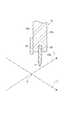
アーム15は、例えば、ロボットアームであり、本体11に固定される基部15a、基部15aに対して水平方向に旋回可能に支持される第1アーム部15b、及び第1アーム部15bに対して上下に揺動自在に連結された第2アーム部15cを備える。アーム15は、基部15aに対して第1アーム部15bが旋回すると共に、第1アーム部15bに対して第2アーム部15cが上下に揺動することにより、カメラ16及び描写部17を3次元方向に移動させる。 The
図2は、アーム15の第2アーム部15cの先端を拡大した断面図である。図2に示されるように、カメラ16は、例えば、第2アーム部15cの先端15dから第2アーム部15cの延在方向に延び出すように第2アーム部15cの側面15eに取り付けられる。カメラ16は、第2アーム部15cの先端15dよりも更に先に位置するレーザ光Lの交点Cを撮影する。描写部17は、例えば、第2アーム部15cの凹部15fに嵌め込まれており、先端15dから第2アーム部15cの延在方向に延び出している。描写部17は、アーム15の3次元方向への移動に伴って交点Cの位置に墨出しを行う。例えば、描写部17は、墨出し用の十字状等の印だけでなく、字又は絵を描写してもよい。 FIG. 2 is an enlarged cross-sectional view of the tip of the
図1に示されるように、建設現場Aには、例えば、2台のレーザ光照射装置20が設けられる。2台のレーザ光照射装置20のそれぞれは、建設現場Aにレーザ光Lを照射して建設現場Aに複数のレーザ光Lが交わる交点Cを形成する。レーザ光照射装置20は、建設現場Aの床面、壁面又は天井面に墨出し用の交点Cを表示する。一例として、レーザ光Lは赤色の可視光線であり、レーザ光Lの波長は635nm以上且つ642nm以下であってもよい。レーザ光照射装置20は、例えば、三脚の上に設置されてもよい。 As shown in FIG. 1, at the construction site A, for example, two laser
座標指定装置30は、墨出しを行う位置の座標を指定する装置である。座標指定装置30は、例えば無線通信によって、ロボット10及びレーザ光照射装置20のそれぞれと通信可能である。座標指定装置30によって座標が指定されると、指定された座標がロボット10及びレーザ光照射装置20に出力される。座標指定装置30は、ロボット10及びレーザ光照射装置20を制御するコントローラであってもよい。また、座標指定装置30は、タブレット又は携帯端末等の端末機器であってもよい。 The coordinate
座標指定装置30によって指定された座標にレーザ光照射装置20は交点Cを表示し、ロボット10は建設現場Aの指定された座標(交点Cの位置)に移動して墨出しを行う。ロボット10は、交点Cの付近に移動すると共にアーム15のカメラ16によって交点Cの位置を認識し、アーム15に取り付けられた描写部17を交点Cに当てて線又は点を描く。なお、ロボット10は、位置座標、又は施工に必要な情報を交点Cに描写してもよい。 The laser
次に、実施形態に係る自律移動方法の具体例について図3及び図4を参照しながら説明する。図3は、自律移動方法の各工程の一例を示すフローチャートである。図4は、建設現場Aの座標の例を示す図である。なお、図4では、ロボット10、カメラ16及びレーザ光照射装置20の図示を簡略化している。以下では、自律移動装置1を用いて建設現場Aに墨出しを行う例について説明する。まず、初期段階として、建設現場Aにロボット10及びレーザ光照射装置20を設置する(ステップS1)。また、例えば基準点P1,P2を既知点とすると共に、ロボット10を基準点P1の付近に配置して各レーザ光照射装置20を点P3,P4のそれぞれに配置する。 Next, a specific example of the autonomous movement method according to the embodiment will be described with reference to FIGS. 3 and 4. FIG. 3 is a flowchart showing an example of each step of the autonomous movement method. FIG. 4 is a diagram showing an example of the coordinates of the construction site A. Note that FIG. 4 simplifies the illustration of the
次に、座標指定装置30によって目標点(位置座標)の発信を行う(ステップS2)。このとき、座標指定装置30から、墨出しを行う目標点P5,P6,P7,P8のそれぞれの座標をロボット10及びレーザ光照射装置20に発信する。各レーザ光照射装置20は、目標点P5,P6,P7,P8の座標を受信すると、レーザ光Lの照射方向を定めるために回転し、基準点P1の位置に交点Cを表示する(ステップS3、交点を表示する工程)。 Next, the coordinate
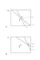
基準点P1に交点Cが表示されると、カメラ16が基準点P1に表示された交点Cを撮影する(ステップS4)。ロボット10は、現在のロボット10の中心点P9に対する交点Cの位置及び向きをカメラ16の撮影画像によって認識し、自己の位置及び向きを設定する(ステップS5、自己の位置及び向きを認識する工程)。具体的には、図5(a)及び図5(b)のカメラ16の撮影画像Bに示されるように、ロボット10は、撮影画像Bに表示される基準点P1の位置を認識し、撮影画像Bの中心点P10を基準点P1に合わせる。 When the intersection C is displayed at the reference point P1, the
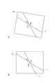
そして、図6(a)及び図6(b)に示されるように、カメラ16の向きが2本のレーザ光Lの交差角度θ1となるようにカメラ16の傾きを調整し、カメラ16の向きがX軸及びY軸の双方に合うようにカメラ16を回転する。そして、カメラ16の位置を基準点P1、X軸に対するカメラ16の中心線が成す角度θ3を90°にするようにカメラ16を移動させると共に、ロボット10の位置と方向角θ2を決定する。 Then, as shown in FIGS. 6A and 6B, the inclination of the
続いて、レーザ光照射装置20を回転し目標点P5の位置に交点Cを表示する(ステップS6)。そして、ロボット10は、自己の位置及び向きに基づいて墨出しの位置である目標点P5に表示された交点Cに向かって移動する(ステップS7、移動する工程)。ロボット10は、目標点P5に向かって移動した後、目標点P5に表示された交点Cの位置と交差角度θ1をカメラ16の撮影によって認識し、自己の位置及び向きを補正すると共に目標点P5に墨出しを行う(ステップS8)。 Subsequently, the laser
目標点P5に墨出しを行った後には、全ての目標点(位置座標)に対する墨出しが完了したか否かを判定する(ステップS9)。例えば、目標点が目標点P5,P6,P7,P8であって目標点P5のみに墨出しを行った時点では、全ての目標点に対する墨出しが完了していないので、ステップS6に戻りステップS6〜S8を再度実行する。ロボット10は、カメラ16による交点Cの撮影画像から目標点P6に対する位置の誤差を算出し、算出した誤差から向き及び次の移動量を算出する。このように、目標点P6,P7,P8への交点Cの表示、交点Cへのロボット10の移動、及び目標点P6,P7,P8への墨出し、を目標点ごとに実行する。そして、全ての目標点に対する墨出しが完了した後に、一連の工程が完了する。 After marking the target points P5, it is determined whether or not the marking for all the target points (position coordinates) is completed (step S9). For example, when the target points are the target points P5, P6, P7, and P8 and only the target points P5 are marked, the marking for all the target points is not completed, so the process returns to step S6 and step S6. ~ S8 is executed again. The
次に、本実施形態に係る自律移動方法及び自律移動装置1から得られる作用効果について説明する。本実施形態に係る自律移動方法及び自律移動装置1は、複数のレーザ光照射装置20のそれぞれからレーザ光Lを照射し、複数のレーザ光Lが交差して形成されるレーザ光Lの交点Cを表示する。ロボット10は、複数のレーザ光照射装置20によって表示された交点Cを撮影するカメラ16を備え、カメラ16によって撮影された交点Cから自己の位置及び向きを認識する。このように、ロボット10は、レーザ光Lの交点Cから自己の位置及び向きを認識し、認識した位置及び向きに基づいて移動するので、レーザ光Lの交点Cを利用することによってロボット10の位置及び向きの認識の精度を高めることができる。 Next, the autonomous movement method and the operation and effect obtained from the autonomous movement device 1 according to the present embodiment will be described. The autonomous movement method and the autonomous movement device 1 according to the present embodiment irradiate the laser light L from each of the plurality of laser
すなわち、ロボット10はレーザ光照射装置20とは別体とされており、ロボット10とレーザ光照射装置20との間に機械的誤差は生じないので、位置及び向きの認識の精度を高めることができる。また、レーザ光Lの交点Cは、地面だけでなく壁、天井及び段差にも表示可能であり、ロボット10を壁、天井又は段差の近くに移動させてロボット10に作業をさせることができるので、ロボット10による作業を効率よく行うことができる。 That is, the
また、図1に示されるように、ロボット10は、カメラ16を移動自在に保持するアーム15を備える。従って、ロボット10は、アーム15を自在に動かすことによってカメラ16を任意の位置に効率よく移動させることができる。その結果、ロボット10の作業性を更に高めることができる。 Further, as shown in FIG. 1, the
また、本実施形態に係る自律移動方法では、ロボット10及び複数のレーザ光照射装置20を配置して座標指定装置30を操作することにより、自動的に墨出し等の作業を行うことができる。従って、熟練していない作業者であっても、座標指定装置30の簡易な操作によって容易に作業を進めることができる。そして、ロボット10及び複数のレーザ光照射装置20によって無人化による作業を行うことができるため、墨出し等の作業の生産性を高めることができる。更に、自動的に作業を行うことによってヒューマンエラーの発生を防止することができる。 Further, in the autonomous movement method according to the present embodiment, by arranging the
また、本実施形態に係る自律移動方法及び自律移動装置1では、ロボット10及び複数のレーザ光照射装置20を用いて墨出し等の作業を行うため、トータルステーション及びプリズム等の視準部材を不要とすることができる。従って、トータルステーション及びプリズム等を用いる場合と比較して簡易な構成とすることができるので、墨出し等の作業を簡易な構成で容易に行うことができる。 Further, in the autonomous movement method and the autonomous movement device 1 according to the present embodiment, since the
また、本実施形態に係る自律移動方法は、ロボット10の位置測定から目標点P5,P6,P7,P8の調整までのプロセスが少ないので、測定の誤差が生じにくい。更に、表示された交点Cに描写部17によって点又は線等を描写して作業を行うことができるため、レーザ光Lの照射の精度のみに依存して墨出しを行うことができる。従って、墨出しを容易に且つ高精度に行うことができる。また、墨出しを行う目標点P5,P6,P7,P8が段差、壁又は天井に位置していてもレーザ光Lの照射が可能であるため、建設現場Aの様々な場所に対して自動的に墨出しを行うことができる。 Further, in the autonomous movement method according to the present embodiment, since the process from the position measurement of the
以上、本発明に係る自律移動方法及び自律移動装置の実施形態について説明したが、本発明は、前述した実施形態に限られるものではなく、各請求項に記載した要旨を変更しない範囲において変形し、又は他のものに適用したものであってもよい。すなわち、自律移動方法の工程の内容及び順序、並びに、自律移動装置の各部の構成は、各請求項の要旨を変更しない範囲において種々の変形が可能である。 Although the autonomous movement method and the embodiment of the autonomous movement device according to the present invention have been described above, the present invention is not limited to the above-described embodiment, and the present invention is modified without changing the gist described in each claim. , Or it may be applied to other things. That is, the contents and order of the steps of the autonomous moving method and the configuration of each part of the autonomous moving device can be variously modified without changing the gist of each claim.
例えば、前述の実施形態では、本体11、車輪12、周辺検知カメラ13及びアーム15を備えるロボット10について説明したが、ロボットの形状、大きさ及び数は適宜可能である。例えば、車輪12の種類又は数を変更してもよいし、アーム15の構成を変更してもよいし、周辺検知カメラ13を省略してもよい。また、レーザ光照射装置及び座標指定装置の形状、大きさ、数及び種類についても適宜変更可能である。 For example, in the above-described embodiment, the
また、前述の実施形態では、建設現場Aにおいて施工の基準となる点又は線を床、壁又は天井に描写する墨出しを自動的に行う自律移動装置1について説明したが、自律移動装置及び自律移動方法では、墨出し以外の作業を行ってもよい。例えば、描写部17に代えて、ドライバをアーム15に装着してロボット10にボルト締めをさせてもよい。また、溶接ガンをアーム15に装着してロボット10に溶接をさせてもよい。このように、本発明に係る自律移動方法及び自律移動装置は、様々な作業に適用することができる。 Further, in the above-described embodiment, the autonomous moving device 1 that automatically draws a point or line that serves as a reference for construction on the floor, wall, or ceiling at the construction site A has been described. In the moving method, work other than marking may be performed. For example, instead of the
1…自律移動装置、10…ロボット、11…本体。12…車輪、13…周辺検知カメラ、15…アーム、15a…基部、15b…第1アーム部、15c…第2アーム部、15d…先端、15e…側面、16…カメラ、17…描写部、20…レーザ光照射装置、30…座標指定装置、A…建設現場、B…撮影画像、C…交点、L…レーザ光、P1,P2…基準点、P3,P4…点、P5,P6,P7,P8…目標点、P9,P10…中心点、θ1…交差角度、θ2…方向角、θ3…角度。1 ... autonomous mobile device, 10 ... robot, 11 ... main body. 12 ... Wheels, 13 ... Peripheral detection camera, 15 ... Arm, 15a ... Base, 15b ... First arm, 15c ... Second arm, 15d ... Tip, 15e ... Side, 16 ... Camera, 17 ... Depiction, 20 ... Laser light irradiation device, 30 ... Coordinate designation device, A ... Construction site, B ... Photographed image, C ... Intersection point, L ... Laser light, P1, P2 ... Reference point, P3, P4 ... Point, P5, P6, P7, P8 ... target point, P9, P10 ... center point, θ1 ... intersection angle, θ2 ... direction angle, θ3 ... angle.
Claims (1)
Translated fromJapanese座標指定位置によって複数のレーザ光照射装置及び前記ロボットに目標点となる座標の発信を行う工程と、
前記複数のレーザ光照射装置のそれぞれからレーザ光を照射して前記レーザ光の交点である基準点を表示する工程と、
前記ロボットのカメラが前記基準点を撮影することによって前記ロボットが自己の位置及び向きを認識する工程と、
前記複数のレーザ光照射装置のそれぞれからレーザ光を照射して前記レーザ光の交点である目標点を表示する工程と、
前記目標点に向かって前記ロボットが移動する工程と、
前記ロボットのカメラが前記目標点を撮影することによって前記ロボットが自己の位置及び向きを補正する工程と、
を備える自律移動方法。It is an autonomous movement method that moves the robot autonomously.
A process of transmitting coordinates as a target point to a plurality of laser beam irradiation devices and the robot according to a coordinate specified position, and
A step of irradiating a laser beam to display areference point which is the intersection of the laser beam from each ofsaid plurality of laser beam irradiation device,
A process in which the robot recognizes its own position and orientation by photographing thereference point with the camera of the robot.
A step of irradiating laser light from each of the plurality of laser light irradiation devices to display a target point which is an intersection of the laser light, and a step of displaying the target point.
The process of moving the robot toward the target point and
A process in which the robot corrects its own position and orientation by photographing the target point with the camera of the robot.
Autonomous movement method equipped with.
Priority Applications (1)
| Application Number | Priority Date | Filing Date | Title |
|---|---|---|---|
| JP2017242848AJP6868544B2 (en) | 2017-12-19 | 2017-12-19 | Autonomous movement method and autonomous movement device |
Applications Claiming Priority (1)
| Application Number | Priority Date | Filing Date | Title |
|---|---|---|---|
| JP2017242848AJP6868544B2 (en) | 2017-12-19 | 2017-12-19 | Autonomous movement method and autonomous movement device |
Publications (2)
| Publication Number | Publication Date |
|---|---|
| JP2019109155A JP2019109155A (en) | 2019-07-04 |
| JP6868544B2true JP6868544B2 (en) | 2021-05-12 |
Family
ID=67179540
Family Applications (1)
| Application Number | Title | Priority Date | Filing Date |
|---|---|---|---|
| JP2017242848AActiveJP6868544B2 (en) | 2017-12-19 | 2017-12-19 | Autonomous movement method and autonomous movement device |
Country Status (1)
| Country | Link |
|---|---|
| JP (1) | JP6868544B2 (en) |
Families Citing this family (1)
| Publication number | Priority date | Publication date | Assignee | Title |
|---|---|---|---|---|
| CN115122323A (en)* | 2019-08-09 | 2022-09-30 | 科沃斯机器人股份有限公司 | Autonomous mobile device |
Family Cites Families (3)
| Publication number | Priority date | Publication date | Assignee | Title |
|---|---|---|---|---|
| JP3731123B2 (en)* | 2002-12-20 | 2006-01-05 | 新菱冷熱工業株式会社 | Object position detection method and apparatus |
| JP2005257656A (en)* | 2004-03-08 | 2005-09-22 | Osamu Matsubara | Pc (cad)-operated laser marking device |
| JP2017075901A (en)* | 2015-10-16 | 2017-04-20 | 株式会社東芝 | Marking work device and marking work method |
- 2017
- 2017-12-19JPJP2017242848Apatent/JP6868544B2/enactiveActive
Also Published As
| Publication number | Publication date |
|---|---|
| JP2019109155A (en) | 2019-07-04 |
Similar Documents
| Publication | Publication Date | Title |
|---|---|---|
| CN107891414B (en) | Robot system | |
| US9197810B2 (en) | Systems and methods for tracking location of movable target object | |
| US9207078B2 (en) | Device for measuring and marking space points along horizontally running contour lines | |
| JP4167954B2 (en) | Robot and robot moving method | |
| US20150377606A1 (en) | Projection system | |
| JP6083520B2 (en) | Robot guidance method and apparatus | |
| EP3421930B1 (en) | Three-dimensional shape data and texture information generation system, photographing control program, and three-dimensional shape data and texture information generation method | |
| JP4721007B2 (en) | Marking apparatus and marking method | |
| CN114310868B (en) | Coordinate system correction device and method for robot arm | |
| DE112016002057T5 (en) | THREE-DIMENSIONAL MEASURING DEVICE SOLVIBLY COUPLED WITH A ROBOT ARM ON A MOTORIZED MOBILE PLATFORM | |
| WO2018043525A1 (en) | Robot system, robot system control device, and robot system control method | |
| JP7395877B2 (en) | Robot system and control method | |
| JP6930840B2 (en) | Surveying system | |
| CH709765B1 (en) | Geodesy tool. | |
| JPWO2020003497A1 (en) | Imaging equipment calibration equipment, monitoring equipment, work machines and calibration methods | |
| JP7138856B2 (en) | Bird's eye view presentation system | |
| TW202212081A (en) | Calibration apparatus and calibration method for coordinate system of robotic arm | |
| JP2018189470A (en) | Surveying system | |
| JP6868544B2 (en) | Autonomous movement method and autonomous movement device | |
| EP4155091A1 (en) | Marking apparatus, control method for marking apparatus, and program | |
| JP7184243B2 (en) | POSITION RECOGNIZATION METHOD, POSITION RECOGNIZATION DEVICE, REFERENCE POINT SETTING MOBILE, WORK MOBILE, AND POSITION RECOGNIZATION SYSTEM | |
| KR102253156B1 (en) | Laser distance measuremet and laser distance measuring method | |
| JP2020204552A (en) | measuring device | |
| JP2017052045A (en) | Positional relation data acquisition device and remote control device | |
| CN109471443A (en) | A wheeled robot positioning method and wheeled robot |
Legal Events
| Date | Code | Title | Description |
|---|---|---|---|
| A621 | Written request for application examination | Free format text:JAPANESE INTERMEDIATE CODE: A621 Effective date:20200424 | |
| A131 | Notification of reasons for refusal | Free format text:JAPANESE INTERMEDIATE CODE: A131 Effective date:20210202 | |
| A521 | Request for written amendment filed | Free format text:JAPANESE INTERMEDIATE CODE: A523 Effective date:20210322 | |
| TRDD | Decision of grant or rejection written | ||
| A01 | Written decision to grant a patent or to grant a registration (utility model) | Free format text:JAPANESE INTERMEDIATE CODE: A01 Effective date:20210406 | |
| A61 | First payment of annual fees (during grant procedure) | Free format text:JAPANESE INTERMEDIATE CODE: A61 Effective date:20210412 | |
| R150 | Certificate of patent or registration of utility model | Ref document number:6868544 Country of ref document:JP Free format text:JAPANESE INTERMEDIATE CODE: R150 | |
| R250 | Receipt of annual fees | Free format text:JAPANESE INTERMEDIATE CODE: R250 |