JP6867398B2 - Work machine control system and work machine control method - Google Patents
Work machine control system and work machine control methodDownload PDFInfo
- Publication number
- JP6867398B2 JP6867398B2JP2018541719AJP2018541719AJP6867398B2JP 6867398 B2JP6867398 B2JP 6867398B2JP 2018541719 AJP2018541719 AJP 2018541719AJP 2018541719 AJP2018541719 AJP 2018541719AJP 6867398 B2JP6867398 B2JP 6867398B2
- Authority
- JP
- Japan
- Prior art keywords
- target speed
- flow rate
- work machine
- bucket
- hydraulic
- Prior art date
- Legal status (The legal status is an assumption and is not a legal conclusion. Google has not performed a legal analysis and makes no representation as to the accuracy of the status listed.)
- Active
Links
Images


Classifications
- E—FIXED CONSTRUCTIONS
- E02—HYDRAULIC ENGINEERING; FOUNDATIONS; SOIL SHIFTING
- E02F—DREDGING; SOIL-SHIFTING
- E02F3/00—Dredgers; Soil-shifting machines
- E02F3/04—Dredgers; Soil-shifting machines mechanically-driven
- E02F3/28—Dredgers; Soil-shifting machines mechanically-driven with digging tools mounted on a dipper- or bucket-arm, i.e. there is either one arm or a pair of arms, e.g. dippers, buckets
- E02F3/36—Component parts
- E02F3/42—Drives for dippers, buckets, dipper-arms or bucket-arms
- E02F3/43—Control of dipper or bucket position; Control of sequence of drive operations
- E02F3/431—Control of dipper or bucket position; Control of sequence of drive operations for bucket-arms, front-end loaders, dumpers or the like
- E—FIXED CONSTRUCTIONS
- E02—HYDRAULIC ENGINEERING; FOUNDATIONS; SOIL SHIFTING
- E02F—DREDGING; SOIL-SHIFTING
- E02F3/00—Dredgers; Soil-shifting machines
- E02F3/04—Dredgers; Soil-shifting machines mechanically-driven
- E02F3/28—Dredgers; Soil-shifting machines mechanically-driven with digging tools mounted on a dipper- or bucket-arm, i.e. there is either one arm or a pair of arms, e.g. dippers, buckets
- E02F3/36—Component parts
- E02F3/42—Drives for dippers, buckets, dipper-arms or bucket-arms
- E02F3/43—Control of dipper or bucket position; Control of sequence of drive operations
- E02F3/435—Control of dipper or bucket position; Control of sequence of drive operations for dipper-arms, backhoes or the like
- E—FIXED CONSTRUCTIONS
- E02—HYDRAULIC ENGINEERING; FOUNDATIONS; SOIL SHIFTING
- E02F—DREDGING; SOIL-SHIFTING
- E02F3/00—Dredgers; Soil-shifting machines
- E02F3/04—Dredgers; Soil-shifting machines mechanically-driven
- E02F3/28—Dredgers; Soil-shifting machines mechanically-driven with digging tools mounted on a dipper- or bucket-arm, i.e. there is either one arm or a pair of arms, e.g. dippers, buckets
- E02F3/36—Component parts
- E02F3/42—Drives for dippers, buckets, dipper-arms or bucket-arms
- E02F3/43—Control of dipper or bucket position; Control of sequence of drive operations
- E02F3/435—Control of dipper or bucket position; Control of sequence of drive operations for dipper-arms, backhoes or the like
- E02F3/437—Control of dipper or bucket position; Control of sequence of drive operations for dipper-arms, backhoes or the like providing automatic sequences of movements, e.g. linear excavation, keeping dipper angle constant
- E—FIXED CONSTRUCTIONS
- E02—HYDRAULIC ENGINEERING; FOUNDATIONS; SOIL SHIFTING
- E02F—DREDGING; SOIL-SHIFTING
- E02F9/00—Component parts of dredgers or soil-shifting machines, not restricted to one of the kinds covered by groups E02F3/00 - E02F7/00
- E02F9/20—Drives; Control devices
- E—FIXED CONSTRUCTIONS
- E02—HYDRAULIC ENGINEERING; FOUNDATIONS; SOIL SHIFTING
- E02F—DREDGING; SOIL-SHIFTING
- E02F9/00—Component parts of dredgers or soil-shifting machines, not restricted to one of the kinds covered by groups E02F3/00 - E02F7/00
- E02F9/20—Drives; Control devices
- E02F9/2004—Control mechanisms, e.g. control levers
- E—FIXED CONSTRUCTIONS
- E02—HYDRAULIC ENGINEERING; FOUNDATIONS; SOIL SHIFTING
- E02F—DREDGING; SOIL-SHIFTING
- E02F9/00—Component parts of dredgers or soil-shifting machines, not restricted to one of the kinds covered by groups E02F3/00 - E02F7/00
- E02F9/20—Drives; Control devices
- E02F9/22—Hydraulic or pneumatic drives
- E02F9/2221—Control of flow rate; Load sensing arrangements
- E02F9/2232—Control of flow rate; Load sensing arrangements using one or more variable displacement pumps
- E02F9/2235—Control of flow rate; Load sensing arrangements using one or more variable displacement pumps including an electronic controller
- E—FIXED CONSTRUCTIONS
- E02—HYDRAULIC ENGINEERING; FOUNDATIONS; SOIL SHIFTING
- E02F—DREDGING; SOIL-SHIFTING
- E02F9/00—Component parts of dredgers or soil-shifting machines, not restricted to one of the kinds covered by groups E02F3/00 - E02F7/00
- E02F9/20—Drives; Control devices
- E02F9/22—Hydraulic or pneumatic drives
- E02F9/2264—Arrangements or adaptations of elements for hydraulic drives
- E02F9/2271—Actuators and supports therefor and protection therefor
- E—FIXED CONSTRUCTIONS
- E02—HYDRAULIC ENGINEERING; FOUNDATIONS; SOIL SHIFTING
- E02F—DREDGING; SOIL-SHIFTING
- E02F9/00—Component parts of dredgers or soil-shifting machines, not restricted to one of the kinds covered by groups E02F3/00 - E02F7/00
- E02F9/26—Indicating devices
- E02F9/261—Surveying the work-site to be treated
- E02F9/262—Surveying the work-site to be treated with follow-up actions to control the work tool, e.g. controller
- F—MECHANICAL ENGINEERING; LIGHTING; HEATING; WEAPONS; BLASTING
- F15—FLUID-PRESSURE ACTUATORS; HYDRAULICS OR PNEUMATICS IN GENERAL
- F15B—SYSTEMS ACTING BY MEANS OF FLUIDS IN GENERAL; FLUID-PRESSURE ACTUATORS, e.g. SERVOMOTORS; DETAILS OF FLUID-PRESSURE SYSTEMS, NOT OTHERWISE PROVIDED FOR
- F15B21/00—Common features of fluid actuator systems; Fluid-pressure actuator systems or details thereof, not covered by any other group of this subclass
- F15B21/08—Servomotor systems incorporating electrically operated control means
- F15B21/087—Control strategy, e.g. with block diagram
- E—FIXED CONSTRUCTIONS
- E02—HYDRAULIC ENGINEERING; FOUNDATIONS; SOIL SHIFTING
- E02F—DREDGING; SOIL-SHIFTING
- E02F9/00—Component parts of dredgers or soil-shifting machines, not restricted to one of the kinds covered by groups E02F3/00 - E02F7/00
- E02F9/20—Drives; Control devices
- E02F9/22—Hydraulic or pneumatic drives
- E02F9/2278—Hydraulic circuits
- E02F9/2285—Pilot-operated systems
- E—FIXED CONSTRUCTIONS
- E02—HYDRAULIC ENGINEERING; FOUNDATIONS; SOIL SHIFTING
- E02F—DREDGING; SOIL-SHIFTING
- E02F9/00—Component parts of dredgers or soil-shifting machines, not restricted to one of the kinds covered by groups E02F3/00 - E02F7/00
- E02F9/20—Drives; Control devices
- E02F9/22—Hydraulic or pneumatic drives
- E02F9/2278—Hydraulic circuits
- E02F9/2292—Systems with two or more pumps
- E—FIXED CONSTRUCTIONS
- E02—HYDRAULIC ENGINEERING; FOUNDATIONS; SOIL SHIFTING
- E02F—DREDGING; SOIL-SHIFTING
- E02F9/00—Component parts of dredgers or soil-shifting machines, not restricted to one of the kinds covered by groups E02F3/00 - E02F7/00
- E02F9/20—Drives; Control devices
- E02F9/22—Hydraulic or pneumatic drives
- E02F9/2278—Hydraulic circuits
- E02F9/2296—Systems with a variable displacement pump
- F—MECHANICAL ENGINEERING; LIGHTING; HEATING; WEAPONS; BLASTING
- F15—FLUID-PRESSURE ACTUATORS; HYDRAULICS OR PNEUMATICS IN GENERAL
- F15B—SYSTEMS ACTING BY MEANS OF FLUIDS IN GENERAL; FLUID-PRESSURE ACTUATORS, e.g. SERVOMOTORS; DETAILS OF FLUID-PRESSURE SYSTEMS, NOT OTHERWISE PROVIDED FOR
- F15B2211/00—Circuits for servomotor systems
- F15B2211/60—Circuit components or control therefor
- F15B2211/63—Electronic controllers
- F15B2211/6303—Electronic controllers using input signals
- F15B2211/6346—Electronic controllers using input signals representing a state of input means, e.g. joystick position
- F—MECHANICAL ENGINEERING; LIGHTING; HEATING; WEAPONS; BLASTING
- F15—FLUID-PRESSURE ACTUATORS; HYDRAULICS OR PNEUMATICS IN GENERAL
- F15B—SYSTEMS ACTING BY MEANS OF FLUIDS IN GENERAL; FLUID-PRESSURE ACTUATORS, e.g. SERVOMOTORS; DETAILS OF FLUID-PRESSURE SYSTEMS, NOT OTHERWISE PROVIDED FOR
- F15B2211/00—Circuits for servomotor systems
- F15B2211/60—Circuit components or control therefor
- F15B2211/665—Methods of control using electronic components
- F15B2211/6654—Flow rate control
Landscapes
- Engineering & Computer Science (AREA)
- Mining & Mineral Resources (AREA)
- General Engineering & Computer Science (AREA)
- Civil Engineering (AREA)
- Structural Engineering (AREA)
- Mechanical Engineering (AREA)
- Physics & Mathematics (AREA)
- Fluid Mechanics (AREA)
- Life Sciences & Earth Sciences (AREA)
- General Life Sciences & Earth Sciences (AREA)
- Paleontology (AREA)
- Chemical & Material Sciences (AREA)
- Analytical Chemistry (AREA)
- Operation Control Of Excavators (AREA)
Description
Translated fromJapanese本発明は、作業機械の制御システム及び作業機械の制御方法に関する。 The present invention relates to a work machine control system and a work machine control method.
油圧ショベルのような作業機械に係る技術分野において、特許文献1に開示されているような、掘削対象の目標形状を示す目標掘削地形に沿って作業機が移動するように作業機を制御する作業機械が知られている。 In the technical field related to a work machine such as a hydraulic excavator, a work of controlling the work machine so that the work machine moves along a target excavation terrain indicating a target shape of an excavation target as disclosed in
作業機を用いる掘削作業において、掘削初期(掘削開始時)に作業機の先端部が落ち込む現象が発生する可能性がある。作業機の先端部が落ち込む原因として、掘削初期に作業機が高速で移動するように操作されることが挙げられる。作業機の先端部が落ち込むと、作業機の先端部が目標掘削地形を超えてしまい、掘削精度が低下する可能性がある。 In excavation work using a work machine, there is a possibility that the tip of the work machine may drop at the initial stage of excavation (at the start of excavation). One of the causes of the tip of the working machine being depressed is that the working machine is operated to move at high speed at the initial stage of excavation. If the tip of the work machine is depressed, the tip of the work machine may exceed the target excavation terrain and the excavation accuracy may decrease.
本発明の態様は、掘削精度の低下を抑制できる技術を提供することを目的とする。 An object of the present invention is to provide a technique capable of suppressing a decrease in excavation accuracy.
本発明の態様に従えば、バケットとアームとブームとを有する作業機を備える作業機械の制御システムであって、油圧ポンプから吐出される作動油の最大流量を算出するポンプ最大流量算出部と、前記油圧ポンプから吐出された前記作動油が供給され前記作業機を駆動させる複数の油圧アクチュエータを駆動するために操作される操作装置の操作量及び前記バケットと目標掘削地形との距離に基づいて、前記作業機の第1目標速度を算出する第1目標速度算出部と、前記最大流量と、前記操作装置の操作量及び前記バケットと目標掘削地形との距離に基づいて、前記作業機の第2目標速度を算出する第2目標速度算出部と、前記第1目標速度及び前記第2目標速度のうち小さい方の目標速度に基づいて、前記油圧アクチュエータを制御する制御信号を出力する作業機制御部と、を備える作業機械の制御システムが提供される。 According to the aspect of the present invention, a control system for a work machine including a work machine having a bucket, an arm, and a boom, a pump maximum flow rate calculation unit for calculating the maximum flow rate of hydraulic oil discharged from the hydraulic pump, and a pump maximum flow rate calculation unit. Based on the operating amount of the operating device operated to drive the plurality of hydraulic actuators to which the hydraulic oil discharged from the hydraulic pump is supplied and driving the working machine, and the distance between the bucket and the target excavation terrain. The second target speed calculation unit of the work machine, the maximum flow rate, the operation amount of the operation device, and the distance between the bucket and the target excavation terrain, and the second target speed calculation unit of the work machine. A second target speed calculation unit that calculates a target speed, and a work equipment control unit that outputs a control signal for controlling the hydraulic actuator based on the smaller target speed of the first target speed and the second target speed. And, a work machine control system is provided.
本発明の態様によれば、掘削精度の低下を抑制できる技術が提供される。 According to the aspect of the present invention, there is provided a technique capable of suppressing a decrease in excavation accuracy.
以下、本発明に係る実施形態について図面を参照しながら説明するが、本発明はこれに限定されない。以下で説明する各実施形態の構成要素は適宜組み合わせることができる。また、一部の構成要素を用いない場合もある。 Hereinafter, embodiments according to the present invention will be described with reference to the drawings, but the present invention is not limited thereto. The components of each embodiment described below can be combined as appropriate. In addition, some components may not be used.
[作業機械]
図1は、本実施形態に係る作業機械100の一例を示す斜視図である。本実施形態においては、作業機械100が油圧ショベルである例について説明する。以下の説明においては、作業機械100を適宜、油圧ショベル100、と称する。[Working machine]
FIG. 1 is a perspective view showing an example of the
図1に示すように、油圧ショベル100は、油圧により作動する作業機1と、作業機1を支持する上部旋回体2と、上部旋回体2を支持する下部走行体3と、作業機1を操作するための操作装置40と、作業機1を制御する制御装置50とを備える。上部旋回体2は、下部走行体3に支持された状態で旋回軸RXを中心に旋回可能である。 As shown in FIG. 1, the
上部旋回体2は、オペレータが搭乗する運転室4と、エンジン17及び油圧ポンプ42が収容される機械室5と、手すり6とを有する。運転室4は、オペレータが着座する運転席4Sを有する。機械室5は、運転室4の後方に配置される。手すり6は、機械室5の前方に配置される。 The
下部走行体3は、一対の履帯7を有する。履帯7の回転により、油圧ショベル100が走行する。なお、下部走行体3が車輪(タイヤ)でもよい。 The lower traveling body 3 has a pair of tracks 7. The rotation of the track 7 causes the
作業機1は、上部旋回体2に支持される。作業機1は、刃先10を有するバケット11と、バケット11に連結されるアーム12と、アーム12に連結されるブーム13とを有する。バケット11の刃先10は、バケット11に設けられた凸形状の刃の先端部でもよいし、バケット11に設けられたストレート形状の刃の先端部でもよい。 The
バケット11は、アーム12の先端部と連結される。アーム12の基端部は、ブーム13の先端部と連結される。ブーム13の基端部は、上部旋回体2と連結される。 The
バケット11とアーム12とはバケットピンを介して連結される。バケット11は、回転軸AX1を中心に回転可能にアーム12に支持される。アーム12とブーム13とはアームピンを介して連結される。アーム12は、回転軸AX2を中心に回転可能にブーム13に支持される。ブーム13と上部旋回体2とはブームピンを介して連結される。ブーム13は、回転軸AX3を中心に回転可能に上部旋回体2に支持される。 The
なお、バケット11は、チルトバケットでもよい。チルトバケットとは、バケットチルトシリンダの作動により、車幅方向にチルト傾斜可能なバケットである。傾斜地において油圧ショベル100が稼働する場合、バケット11が車幅方向にチルト傾斜することにより、斜面又は平地を円滑に成形又は整地することができる。 The
操作装置40は、運転室4に配置される。操作装置40は、油圧ショベル100のオペレータに操作される操作部材を含む。操作部材は、操作レバー又はジョイスティックを含む。操作部材が操作されることにより、作業機1が操作される。 The
制御装置50は、コンピュータシステムを含む。制御装置50は、CPU(Central Processing Unit)のようなプロセッサを含む演算処理装置と、ROM(Read Only Memory)又はRAM(Random Access Memory)のような記憶装置と、入出力インターフェース装置とを有する。 The
図2は、本実施形態に係る油圧ショベル100を模式的に示す側面図である。図1及び図2に示すように、油圧ショベル100は、作業機1を駆動する油圧シリンダ20を有する。油圧シリンダ20は、作業機1を駆動させる油圧アクチュエータであり、複数設けられる。油圧ポンプ42から吐出された作動油が油圧シリンダ20に供給される。油圧シリンダ20は、作動油によって駆動される。油圧シリンダ20は、バケット11を駆動するバケットシリンダ21と、アーム12を駆動するアームシリンダ22と、ブーム13を駆動するブームシリンダ23とを含む。 FIG. 2 is a side view schematically showing the
図2に示すように、油圧ショベル100は、バケットシリンダ21に配置されたバケットシリンダストロークセンサ14と、アームシリンダ22に配置されたアームシリンダストロークセンサ15と、ブームシリンダ23に配置されたブームシリンダストロークセンサ16とを有する。バケットシリンダストロークセンサ14は、バケットシリンダ21の作動量を示すブームストロークを検出する。アームシリンダストロークセンサ15は、アームシリンダ22の作動量を示すアームストロークを検出する。ブームシリンダストロークセンサ16は、ブームシリンダ23の作動量を示すブームストロークを検出する。 As shown in FIG. 2, the
油圧ショベル100は、上部旋回体2の位置を検出する位置検出装置30を備える。位置検出装置30は、グローバル座標系で規定される上部旋回体2の位置を検出する車体位置検出器31と、上部旋回体2の姿勢を検出する姿勢検出器32と、上部旋回体2の方位を検出する方位検出器33とを含む。 The
グローバル座標系(XgYgZg座標系)とは、全地球測位システム(Global Positioning System:GPS)により規定される絶対位置を示す座標系である。ローカル座標系(XmYmZm座標系)とは、油圧ショベル100の上部旋回体2の基準位置Psとした相対位置を示す座標系である。上部旋回体2の基準位置Psは、例えば、上部旋回体2の旋回軸RXに設定される。なお、上部旋回体2の基準位置Psは、回転軸AX3に設定されてもよい。位置検出装置30によって、グローバル座標系で規定される上部旋回体2の3次元位置、水平面に対する上部旋回体2の姿勢角、及び基準方位に対する上部旋回体2の方位が検出される。 The global coordinate system (XgYgZg coordinate system) is a coordinate system indicating an absolute position defined by the Global Positioning System (GPS). The local coordinate system (XmYmZm coordinate system) is a coordinate system indicating a relative position of the
車体位置検出器31は、GPS受信機を含む。車体位置検出器31は、グローバル座標系で規定される上部旋回体2の3次元位置を検出する。車体位置検出器31は、上部旋回体2のXg方向の位置、Yg方向の位置、及びZg方向の位置を検出する。 The vehicle
上部旋回体2に複数のGPSアンテナ31Aが設けられる。GPSアンテナ31Aは、GPS衛星から電波を受信して、受信した電波に基づく信号を車体位置検出器31に出力する。車体位置検出器31は、GPSアンテナ31Aから供給された信号に基づいて、グローバル座標系で規定されるGPSアンテナ31Aの設置位置P1を検出する。車体位置検出器31は、GPSアンテナ31Aの設置位置P1に基づいて、上部旋回体2の絶対位置Pgを検出する。 A plurality of
車体位置検出器31は、2つのGPSアンテナ31Aのうち一方のGPSアンテナ31Aの設置位置P1a及び他方のGPSアンテナ31Aの設置位置P1bのそれぞれを検出する。車体位置検出器31Aは、設置位置P1aと設置位置P1bとに基づいて演算処理を実施して、上部旋回体2の絶対位置Pg及び方位を検出する。本実施形態において、上部旋回体2の絶対位置Pgは、設置位置P1aである。なお、上部旋回体2の絶対位置Pgは、設置位置P1bでもよい。 The vehicle
姿勢検出器32は、慣性計測装置(Inertial Measurement Unit:IMU)を含む。姿勢検出器32は、上部旋回体2に設けられる。姿勢検出器32は、運転室4の下部に配置される。姿勢検出器32は、水平面(XgYg平面)に対する上部旋回体2の姿勢角を検出する。水平面に対する上部旋回体2の姿勢角は、車幅方向における上部旋回体2の姿勢角θaと、前後方向における上部旋回体2の姿勢角θbと、を含む。 The
方位検出器33は、一方のGPSアンテナ31Aの設置位置P1aと他方のGPSアンテナ31Aの設置位置P1bとに基づいて、グローバル座標系で規定される基準方位に対する上部旋回体2の方位を検出する機能を有する。基準方位は、例えば北である。方位検出器33は、設置位置P1aと設置位置P1bとに基づいて演算処理を実施して、基準方位に対する上部旋回体2の方位を検出する。方位検出器33は、設置位置P1aと設置位置P1bとを結ぶ直線を算出し、算出した直線と基準方位とがなす姿勢角θcに基づいて、基準方位に対する上部旋回体2の方位を検出する。 The
なお、方位検出器33は、位置検出装置30とは別体でもよい。方位検出器33は、磁気センサを用いて上部旋回体2の方位を検出してもよい。 The
油圧ショベル100は、上部旋回体2の基準位置Psに対する刃先10の相対位置を検出する刃先位置検出器34を備える。 The
本実施形態において、刃先位置検出器34は、バケットシリンダストロークセンサ14の検出結果と、アームシリンダストロークセンサ15の検出結果と、ブームシリンダストロークセンサ16の検出結果と、バケット11の長さL11と、アーム12の長さL12と、ブーム13の長さL13とに基づいて、上部旋回体2の基準位置Psに対する刃先10の相対位置を算出する。 In the present embodiment, the cutting
刃先位置検出器34は、バケットシリンダストロークセンサ14の検出データに基づいて、アーム12に対するバケット11の刃先10の姿勢角θ11を算出する。刃先位置検出器34は、アームシリンダストロークセンサ15の検出データに基づいて、ブーム13に対するアーム12の姿勢角θ12を算出する。刃先位置検出器34は、ブームシリンダストロークセンサ16の検出データに基づいて、上部旋回体2のZ軸に対するブーム13の姿勢角θ13を算出する。 The cutting
バケット11の長さL11は、バケット11の刃先10と回転軸AX1(バケットピン)との距離である。アーム12の長さL12は、回転軸AX1(バケットピン)と回転軸AX2(アームピン)との距離である。ブーム13の長さL13は、回転軸AX2(アームピン)と回転軸AX3(ブームピン)との距離である。 The length L11 of the
刃先位置検出器34は、姿勢角θ11、姿勢角θ12、姿勢角θ13、長さL11、長さL12、及び長さL13に基づいて、上部旋回体2の基準位置Psに対する刃先10の相対位置を算出する。 The cutting
また、刃先位置検出器34は、位置検出装置30で検出された上部旋回体2の絶対位置Pgと、上部旋回体2の基準位置Psと刃先10との相対位置とに基づいて、刃先10の絶対位置Pbを算出する。絶対位置Pgと基準位置Psとの相対位置は、油圧ショベル100の設計データ又は諸元データから導出される既知データである。したがって、刃先位置検出器34は、上部旋回体2の絶対位置Pgと、上部旋回体2の基準位置Psと刃先10との相対位置と、油圧ショベル100の設計データ又は諸元データとに基づいて、刃先10の絶対位置Pbを算出可能である。 Further, the cutting
なお、本実施形態においては、姿勢角θ11,θ12,θ13の検出にシリンダストロークセンサ14,15,16が使用されるが、シリンダストロークセンサ14,15,16が使用されなくてもよい。例えば、刃先位置検出器34は、ポテンショメータ等の角度センサ又は水準器等を使って、バケット11の姿勢角θ11、アーム12の姿勢角θ12、及びブーム13の姿勢角θ13を検出してもよい。 In the present embodiment, the
[作業機の動作]
操作装置40は、作業機1を駆動させる複数の油圧アクチュエータ20を駆動するために操作される。操作装置40が操作されることにより、バケット11のダンプ動作、バケット11の掘削動作、アーム12のダンプ動作、アーム12の掘削動作、ブーム13の上げ動作、及びブーム13の下げ動作が実行される。[Operation of work machine]
The operating
バケットシリンダ21が伸びることによりバケット11が掘削動作し、バケットシリンダ21が縮むことによりバケット11がダンプ動作する。アームシリンダ22が伸びることによりアーム12が掘削動作し、アームシリンダ22が縮むことによりアーム12がダンプ動作する。ブームシリンダ23が伸びることによりブーム13が上げ動作し、ブームシリンダ23が縮むことによりブーム13が下げ動作する。 The
本実施形態において、操作装置40は、運転席4Sに着座したオペレータの右側に配置される右操作レバーと、左側に配置される左操作レバーとを含む。 In the present embodiment, the operating
[整地アシスト制御]
図3は、本実施形態に係る整地アシスト制御に基づいて駆動される作業機2の動作の一例を説明するための模式図である。[Leveling assist control]
FIG. 3 is a schematic diagram for explaining an example of the operation of the working
整地アシスト制御とは、掘削対象の目標形状を示す目標掘削地形に沿ってバケット11が移動するように作業機1を制御することをいう。整地アシスト制御においては、バケット11が目標掘削地形を超えないように、ブーム13が上げ動作するようにブームシリンダ23が制御される。 The ground leveling assist control means controlling the
整地アシスト制御においては、バケット11及びアーム12は、オペレータによる操作装置40の操作に基づいて駆動される。ブーム13は、制御装置50による制御に基づいて駆動される。 In the leveling assist control, the
図3に示すように、本実施形態においては、バケット11の刃先10が目標掘削地形に沿って移動するように、整地アシスト制御が実施される。 As shown in FIG. 3, in the present embodiment, the leveling assist control is performed so that the
[油圧システム]
次に、本実施形態に係る油圧システム300の一例について説明する。バケットシリンダ21、アームシリンダ22、及びブームシリンダ23を含む油圧シリンダ20は、油圧システム300により作動する。油圧シリンダ20は、操作装置40及び制御装置50の少なくとも一方により操作される。[Flood system]
Next, an example of the
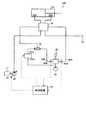
図4は、アームシリンダ22を作動する油圧システム300の一例を示す模式図である。操作装置40の操作により、アーム12は、掘削動作及びダンプ動作の2種類の動作を実行する。アームシリンダ22を作動する油圧システム300は、方向制御弁41を介してアームシリンダ22に作動油を供給する油圧ポンプ42と、パイロット油を供給する油圧ポンプ43と、方向制御弁41に接続されパイロット油が流れる油路44A,44Bと、操作装置40に接続されパイロット油が流れる油路47A,47Bと、油路44A,44B及び油路47A,47Bのそれぞれに接続され方向制御弁41に作用するパイロット圧を調整する制御弁45A,45Bと、油路47A,47Bに配置された圧力センサ49A,49Bと、制御弁45A,45Bを制御する制御装置50と、を備える。 FIG. 4 is a schematic view showing an example of the
油圧ポンプ42は、エンジン17によって駆動される。エンジン17は、油圧ショベル1の動力源である。エンジン17は、例えばディーゼルエンジンである。油圧ポンプ42は、エンジン17の出力シャフトと連結され、エンジン17が駆動することにより作動油を吐出する。油圧シリンダ20は、油圧ポンプ42から吐出された作動油に基づいて作動する。 The
油圧ポンプ42は、可変容量型油圧ポンプである。本実施形態において、油圧ポンプ42は、斜板式油圧ポンプである。油圧ポンプ42の斜板は、サーボ機構18によって駆動される。サーボ機構18により斜板の角度が調整されることによって、油圧ポンプ42の容量[cc/rev]が調整される。油圧ポンプ42の容量とは、油圧ポンプ42と連結されたエンジン17の出力シャフトが1回転したときに油圧ポンプ42から吐出される作動油の吐出量[cc/rev]をいう。 The
制御弁45A,45Bは、電磁比例制御弁である。油圧ポンプ43から送出されたパイロット油は、操作装置40及び油路47A,47Bを介して、制御弁45A,45Bに供給される。なお、油圧ポンプ42から送出され、減圧弁によって減圧されたパイロット油が制御弁45A,45Bに供給されてもよい。制御弁45A,45Bは、制御装置50からの制御信号に基づいて、方向制御弁41に作用するパイロット圧を調整する。制御弁45Aは、油路44Aのパイロット圧を調整する。制御弁45Bは、油路44Bのパイロット圧を調整する。 The
方向制御弁41は、作動油の流量及び作動油が流れる方向を制御する。油圧ポンプ42から供給された作動油は、方向制御弁41を介してアームシリンダ22に供給される。方向制御弁41は、アームシリンダ22のキャップ側油室20Aに対する作動油の供給とロッド側油室20Bに対する作動油の供給とを切り換える。キャップ側油室20Aは、シリンダヘッドカバーとピストンとの間の空間である。ロッド側油室20Bは、ピストンロッドが配置される空間である。 The
操作装置40は、油圧ポンプ43と接続される。油圧ポンプ43から送出されたパイロット油が操作装置40に供給される。なお、油圧ポンプ42から送出され、減圧弁によって減圧されたパイロット油が操作装置40に供給されてもよい。 The operating
図5は、ブームシリンダ23を作動する油圧システム300の一例を示す模式図である。操作装置40の操作により、ブーム13は、上げ動作及び下げ動作の2種類の動作を実行する。ブームシリンダ23を作動する油圧システム300は、油圧ポンプ42と、油圧ポンプ43と、方向制御弁41と、パイロット油が流れる油路44A,44B,44Cと、油路44Cに配置された制御弁45Cと、油路44A,44Bに配置された圧力センサ46A,46Bと、制御弁45Cを制御する制御装置50と、を備える。 FIG. 5 is a schematic view showing an example of the
制御弁45Cは、電磁比例制御弁である。制御弁45Cは、制御装置50からの指令信号に基づいて、パイロット圧を調整する。制御弁45Cは、油路44Cのパイロット圧を調整する。 The
操作装置40が操作されることにより、操作装置40の操作量に応じたパイロット圧が方向制御弁41に作用する。方向制御弁41のスプールは、パイロット圧に応じて移動する。スプールの移動量に基づいて、油圧ポンプ42から方向制御弁41を介してブームシリンダ23に供給される単位時間当たりの作動油の供給量が調整される。 When the operating
本実施形態においては、整地アシスト制御のために、制御装置50から出力された整地アシスト制御に関する制御信号に基づいて作動する制御弁45Cが油路44Cに設けられる。油路44Cに、油圧ポンプ43から送出されたパイロット油が流れる。油路44B及び油路44Cは、シャトル弁48と接続される。シャトル弁48は、油路44B及び油路44Cのうち、パイロット圧が高い方の油路のパイロット油を、方向制御弁41に供給する。制御弁45Cは、整地アシスト制御を実行するために制御装置50から出力された制御信号に基づいて制御される。 In the present embodiment, for the ground leveling assist control, a
整地アシスト制御を実行しないとき、操作装置40の操作によって調整されたパイロット圧に基づいて方向制御弁41が駆動されるように、制御装置50は、制御弁45Cに制御信号を出力しない。例えば、制御装置50は、操作装置40の操作によって調整されたパイロット圧に基づいて方向制御弁41が駆動されるように、制御弁45Cで油路44Cを閉じる。 When the ground leveling assist control is not executed, the
整地アシスト制御を実行するとき、制御装置50は、制御弁45Cによって調整されたパイロット圧に基づいて方向制御弁41が駆動されるように、制御弁45Cを制御する。例えば、ブーム13の移動を制限する整地アシスト制御を実行する場合、制御装置50は、ブーム目標速度に応じたパイロット圧となるように、制御弁45Cを全開状態とする。油路44Cのパイロット圧が油路44Bのパイロット圧より大きくなると、制御弁45Cからのパイロット油がシャトル弁48を介して方向制御弁41に供給される。これにより、ブームシリンダ23が伸び、ブーム13が上げ動作する。 When executing the leveling assist control, the
バケットシリンダ21は、操作装置40の操作量に基づいて作動する。バケットシリンダ21を作動する油圧システム300についての説明は省略する。 The
なお、操作装置40は、電気方式の操作装置でもよい。例えば、操作装置40が、電気レバーのような操作部材と、操作部材の傾倒量を電気的に検出するポテンショメータのような作動量センサとを有してもよい。作動量センサの検出データは、制御装置50に出力される。制御装置50は、操作装置40の操作量として、作動量センサの検出データを取得する。制御装置50は、作動量センサの検出データに基づいて、方向制御弁41を駆動するための制御信号を出力してもよい。また、方向制御弁41がソレノイドのような電力で作動するアクチュエータによって駆動されてもよい。 The operating
[制御システム]
次に、本実施形態に係る油圧ショベル100の制御システム200について説明する。図6は、本実施形態に係る制御システム200の一例を示す機能ブロック図である。[Control system]
Next, the
図6に示すように、制御システム200は、作業機1を制御する制御装置50と、位置検出装置30と、刃先位置検出器34と、制御弁45(45A,45B,45C)と、圧力センサ46(46A,46B)と、圧力センサ49(49A,49B)と、目標掘削地形データ生成装置70とを備える。 As shown in FIG. 6, the
上述したように、車体位置検出器31、姿勢検出器32、及び方位検出器33を含む位置検出装置30は、上部旋回体2の絶対位置Pgを検出する。以下の説明においては、上部旋回体2の絶対位置Pgを適宜、車体位置Pg、と称する。 As described above, the
制御弁45(45A,45B,45C)は、油圧シリンダ20に供給される作動油の流量を調整する。制御弁45は、制御装置50からの制御信号に基づいて作動する。圧力センサ46(46A,46B)は、油路44(44A,44B)のパイロット圧を検出する。圧力センサ49(49A,49B)は、油路47(47A,47B)のパイロット圧を検出する。圧力センサ46の検出データ及び圧力センサ49の検出データは、制御装置50に出力される。 The control valves 45 (45A, 45B, 45C) adjust the flow rate of the hydraulic oil supplied to the
目標掘削地形データ生成装置70は、コンピュータシステムを含む。目標掘削地形データ生成装置70は、掘削対象の目標形状を示す目標掘削地形を生成する。目標掘削地形は、作業機1による施工後に得られる3次元の目標形状を示す。 The target excavation
なお、目標掘削地形データ生成装置70と制御装置50とが有線で接続され、目標掘削地形データ生成装置70から制御装置50に目標掘削地形が送信されてもよい。なお、目標掘削地形データ生成装置70が目標掘削地形を記憶した記憶媒体を含み、制御装置50が、その記憶媒体から目標掘削地形を示すデータを読み込み可能な装置を有してもよい。 The target excavation terrain
制御装置50は、コンピュータシステムを含む。制御装置50は、演算処理装置50Aと、記憶装置50Bと、入出力インターフェース装置50Cとを有する。 The
演算処理装置50Aは、車体位置データ取得部51と、バケット位置データ取得部52と、目標掘削地形データ取得部53と、距離データ取得部54と、操作量データ取得部56と、ポンプ最大流量算出部57と、第1目標速度算出部58と、第2目標速度算出部60と、作業機制御部61とを有する。 The
車体位置データ取得部51は、位置検出装置30から、入出力インターフェース装置50Cを介して、車体位置Pgを示す車体位置データを取得する。車体位置検出器31は、GPSアンテナ31の設置位置P1a及び設置位置P1bの少なくとも一方に基づいて、車体位置Pgを検出する。車体位置データ取得部51は、車体位置検出器31から、車体位置Pgを示す車体位置データを取得する。 The vehicle body position
バケット位置データ取得部52は、刃先位置検出器34から、入出力インターフェース装置50Cを介して、バケット11の位置を含むバケット位置データを取得する。バケット位置データは、上部旋回体2の基準位置Psに対する刃先10の相対位置を含む。 The bucket position
目標掘削地形データ取得部53は、目標掘削地形データ生成装置70から供給される目標掘削地形を示すデータとバケット11の位置とを用いて、バケット11の位置に対応する目標掘削地形データを生成する。 The target excavation terrain data acquisition unit 53 generates target excavation terrain data corresponding to the position of the
距離データ取得部54は、バケット位置データ取得部52で取得されたバケット11の位置と、目標掘削地形データ取得部53で生成された目標掘削地形とに基づいて、バケット11と目標掘削地形との距離Dを算出する。 The distance
なお、バケット11と目標掘削地形との距離Dは、バケット11の刃先10と目標掘削地形との距離でもよいし、バケット11の底面を含むバケット11の任意の位置と目標掘削地形との距離でもよい。 The distance D between the
操作量データ取得部56は、作業機1を操作する操作装置40の操作量を示す操作量データを取得する。バケット11の操作量、アーム12の操作量、及びブーム13の操作量は、圧力センサ46の検出データ又は圧力センサ49の検出データと相関する。操作装置40の操作量と圧力センサ46の検出データ又は圧力センサ49の検出データとの相関を示す相関データは、予備実験又はシミュレーションにより事前に求められ、記憶装置50Bに記憶されている。操作量データ取得部56は、圧力センサ46の検出データ又は圧力センサ49の検出データと、記憶装置50Bに記憶されている相関データとに基づいて、操作装置40の操作量を算出することができる。 The operation amount
例えば、操作量データ取得部56は、圧力センサ49A,49Bの検出データと、記憶装置50Bに記憶されている相関データとに基づいて、アーム12を操作する操作装置40(左操作レバー)の操作量を示すデータを取得することができる。同様に、操作量データ取得部56は、圧力センサ46A,46Bの検出データと、記憶装置50Bに記憶されている相関データとに基づいて、ブーム13を操作する操作装置40(右操作レバー)の操作量を示すデータを取得することができる。 For example, the operation amount
ポンプ最大流量算出部57は、油圧ポンプ42から吐出される作動油の最大流量Qmaxを算出する。最大流量Qmaxとは、ある時点において油圧ポンプ42が吐出可能な作動油の流量Q[l/min]の上限値をいう。操作装置40が操作されていない状態においては、油圧ポンプ42からはゼロを含む少量の流量Qminで作動油が吐出される。操作装置40の操作が開始された操作開始時点から徐々に増加して油圧ポンプ42が吐出可能な最大流量Qmaxに到達するように、最大流量Qmaxの特性が定められる。 The pump maximum flow
最大流量Qmaxは、例えば、油圧ポンプ42の容量[cc/rev]及び油圧ポンプ42を駆動するエンジン17の回転数[rpm]の少なくとも一方に基づいて算出される。ポンプ最大流量算出部57は、例えば、油圧ポンプ42の容量の上限値及びエンジン17の回転数の上限値に基づいて、最大流量Qmaxを算出することができる。なお、油圧ショベル1の運転室4にスロットルダイヤルが設けられている場合、オペレータは、スロットルダイヤルを操作して、エンジン17の回転数の上限値を設定することができる。ポンプ最大流量算出部57は、スロットルダイヤルの操作量に基づいて、最大流量Qmaxを算出することができる。つまり、操作開始時点から徐々に増加した最大流量Qmaxは、スロットルダイヤルの操作量に基づいた、最大流量Qmaxに到達すると一定値となる。スロットルダイヤルの操作量に基づき、一定値は変動する。 The maximum flow rate Qmax is calculated based on, for example, at least one of the capacity [cc / rev] of the
第1目標速度算出部58は、操作装置40の操作量及びバケット11と目標掘削地形との距離Dに基づいて、作業機1の第1目標速度を算出する。すなわち、第1目標速度算出部58は、操作装置40の操作量と距離Dとに基づいて、第1目標速度を算出する。 The first target
第1目標速度は、バケットシリンダ21のバケットシリンダ目標速度Vbk、アームシリンダ22のアームシリンダ目標速度Var、及びブームシリンダ23のブームシリンダ目標速度Vbmを含む。 The first target speed includes the bucket cylinder target speed Vbk of the
図3を参照して説明したように、整地アシスト制御は、バケット11の少なくとも一部が整地アシスト制御範囲に存在するときに実施される。バケット11が整地アシスト制御範囲に存在しない場合、操作装置40の操作量に基づいて、作業機2は駆動される。 As described with reference to FIG. 3, the leveling assist control is performed when at least a part of the
一方、バケット11が整地アシスト範囲に存在する場合、第1目標速度算出部58は、操作装置40の操作量及びバケット11と目標掘削地形との距離Dに基づいて、第1目標速度を算出する。 On the other hand, when the
すなわち、目標掘削地形とバケット11との距離Dが閾値H以下であり、整地アシスト制御が実施されるとき、第1目標速度算出部58は、操作装置40の操作量及び距離Dに基づいて、作業機制限速度Vtを算出する。作業機制限速度Vtは、操作装置40の操作量及び距離Dに基づいて算出された整地アシスト制御のための作業機1全体の制限速度を示す。距離Dが小さくなるほど、作業機制限速度Vtは小さくなり、距離Dがゼロになると、作業機制限速度Vtもゼロになる。 That is, when the distance D between the target excavation terrain and the
作業機制限速度Vtは、作業機1全体の制限速度を示す。作業機1全体の速度とは、バケット11、アーム12、及びブーム13が駆動したときのバケット11の実際の動作速度をいう。また、第1目標速度算出部58は、作業機制限速度Vtに基づいて、ブームシリンダ目標速度Vbmを算出する。第1目標速度算出部58は、オペレータによる操作装置40の操作量に基づいて、アームシリンダ目標速度Vamとバケットシリンダ目標速度Vbkを算出する。すなわち、本実施形態において、第1目標速度算出部58は、作業機制限速度Vtと、操作量データ取得部56で取得された少なくともアーム操作量及びバケット操作量による作業機1全体の速度と作業機制限速度Vtとの偏差が相殺されるように、ブームシリンダ目標速度Vbmとを算出する。第1目標速度算出部58においては、バケット11の動き及びアーム12の動きは、オペレータによる操作装置40の操作に基づく。整地アシスト制御において、操作装置40によりバケット11及びアーム12が操作されている状態で、目標掘削地形に沿ってバケット11の刃先10が移動するように、第1目標速度算出部58は、上げ動作するブーム10のブームシリンダ目標速度Vbmを算出する。 The work machine speed limit Vt indicates the speed limit of the
第2目標速度算出部60は、ポンプ最大流量算出部57で算出された最大流量Qmaxと、操作装置40の操作量及び距離Dに基づいて、作業機1の第2目標速度を算出する。すなわち、第2目標速度算出部60は、最大流量Qmaxと操作装置40の操作量と距離Dとに基づいて、第2目標速度を算出する。 The second target
第2目標速度算出部60は、ブーム13をブームシリンダ目標速度Vbmで作動させるためにブームシリンダ23が要求する作動油の要求流量Qdbmを算出する。第2目標速度算出部60は、アーム12をアームシリンダ目標速度Varで作動させるためにアームシリンダ22が要求する作動油の要求流量Qdarを算出する。 The second target
以下の説明においては、複数の油圧シリンダ20の要求流量Qdの和を適宜、合計流量Qdal、と称する。なお、バケットシリンダ21の要求流量Qdbkは、アームシリンダ22の要求流量Qdar及びブームシリンダ23の要求流量Qdbmに比べて少ない場合が多い。そのため、本実施形態においては、説明を簡単にするため、合計流量Qdalが、アームシリンダ22の要求流量Qdarとブームシリンダ23の要求流量Qdbmとの和であることとする。 In the following description, the sum of the required flow rates Qd of the plurality of
作業機1の第2目標速度とは、ポンプ最大流量算出部57で算出された最大流量Qmaxと操作装置40の操作量及び距離Dに基づいて算出された作業機制限速度Vtとに基づいて目標速度を再演算することによって算出されたバケットシリンダ目標速度Vbk、アームシリンダ目標速度Var、及びブームシリンダ目標速度Vbmをいう。上述のように、第1目標速度算出部58は、操作装置40の操作量及び距離Dに基づいて、第1目標速度を算出する。第2目標速度算出部60は、最大流量Qmaxと、操作装置40の操作量及び距離Dに基づいて、第2目標速度を算出する。 The second target speed of the
本実施形態において、第2目標速度算出部60は、アームシリンダ22の要求流量Qdarとブームシリンダ23の要求流量Qdbmとの和を示す合計流量Qdalがポンプ最大流量算出部57で算出された最大流量Qmaxになるように、整地アシスト制御における作業機1の第2目標速度を算出する。 In the present embodiment, the second target
すなわち、本実施形態において、第2目標速度算出部60は、ポンプ最大流量算出部57で算出された最大流量Qmaxと操作装置40の操作量及び距離Dに基づいて算出された作業機制限速度Vtを拘束条件として、第1目標速度算出部58で算出されるバケットシリンダ目標速度Vbk、アームシリンダ目標速度Var、及びブームシリンダ目標速度Vbmのそれぞれを再演算して、アームシリンダ目標速度Var及びブームシリンダ目標速度Vbmの再演算値を算出する。 That is, in the present embodiment, the second target
ポンプ最大流量算出部57で算出された最大流量をQmax、操作装置40の操作量及び距離Dに基づいて算出された作業機制限速度Vtになるように作業機1を作動したときのアームシリンダ22の作動によるバケット11の速度をVs、作業機制限速度Vtになるように作業機1を作動したときのアームシリンダ22の要求流量をQdar、作業機制限速度Vtになるように作業機1を作動したときのブームシリンダ23の作動によるバケット11の速度をVb、作業機制限速度Vtになるように作業機1を作動したときのブームシリンダ23の要求流量をQdbmとしたとき、第2目標速度算出部60は、以下の連立方程式を演算処理して、アームシリンダ目標速度Var及びブームシリンダ目標速度Vbmの再演算値を算出する。つまり、第2目標速度算出部60は、アームシリンダ22の要求流量Qdarとブームシリンダ23の要求流量Qdbmの和が最大流量Qmaxを満足し、かつ作業機制限速度Vtになるように、アームシリンダ22の作動によるバケット11の速度Vsとブームシリンダ23の作動によるバケット11の速度Vbを求めることで、各シリンダの要求流量の再演算値を算出する。

以下の説明においては、第1目標速度算出部58で算出されたアームシリンダ目標速度Varを適宜、再演算前のアームシリンダ目標速度Var_b、と称し、第2目標速度算出部60で再演算により算出されたアームシリンダ目標速度Varを適宜、再演算後のアームシリンダ目標速度Var_a、と称する。また、第1目標速度算出部58で算出されたブームシリンダ目標速度Vbmを適宜、再演算前のブームシリンダ目標速度Vbm_b、と称し、第2目標速度算出部60で再演算により算出されたブームシリンダ目標速度Vbmを適宜、再演算後のブームシリンダ目標速度Vbm_a、と称する。すなわち、本実施形態において、第1目標速度は、再演算前の作業機1の目標速度であり、第2目標速度は、再演算後の作業機1の目標速度である。 In the following description, the arm cylinder target speed Var calculated by the first target
作業機制御部61は、目標速度で作業機1が作動するように、油圧シリンダ20を制御する制御信号を制御弁45に出力する。本実施形態において、作業機制御部61は、第1目標速度及び第2目標速度のうち小さい方の目標速度に基づいて、油圧シリンダ20を制御する制御信号を出力する。 The work
図7は、本実施形態に係る作業機1の目標速度の決定方法を説明するための図である。図7に示すグラフにおいて、横軸は、整地アシスト制御が開始された時点からの経過時間を示し、縦軸は、アーム12及びブーム13の目標速度を示す。 FIG. 7 is a diagram for explaining a method of determining the target speed of the working
整地アシスト制御が開始された時点とは、距離Dが閾値Hよりも大きい状態から閾値Dになった時点をいう。 The time when the leveling assist control is started means the time when the distance D becomes the threshold D from the state where the distance D is larger than the threshold H.
例えば、作業機制御部61は、再演算前のアームシリンダ目標速度Var_bと再演算後のアームシリンダ目標速度Var_aとを比較し、再演算前のアームシリンダ目標速度Var_bが再演算後のアームシリンダ目標速度Var_aよりも小さいと判定したとき、アームシリンダ目標速度Varを、再演算前のアームシリンダ目標速度Var_bに決定する。作業機制御部61は、アームシリンダ22が再演算前のアームシリンダ目標速度Var_bで作動するように、制御弁45(45A,45B)に制御信号を出力する。 For example, the work
また、作業機制御部61は、再演算前のアームシリンダ目標速度Var_bと再演算後のアームシリンダ目標速度Var_aとを比較し、再演算後のアームシリンダ目標速度Var_aが再演算前のアームシリンダ目標速度Var_bよりも小さいと判定したとき、アームシリンダ目標速度Varを、再演算後のアームシリンダ目標速度Var_aに決定する。作業機制御部61は、アームシリンダ22が再演算後のアームシリンダ目標速度Var_aで作動するように、制御弁45(45A,45B)に制御信号を出力する。 Further, the work
図7において、ラインVar_fは、決定されたアームシリンダ目標速度Varを示す。 In FIG. 7, the line Var_f indicates the determined arm cylinder target speed Var.
同様に、作業機制御部61は、再演算前のブームシリンダ目標速度Vbm_bと再演算後のブームシリンダ目標速度Vbm_aとを比較し、再演算前のブームシリンダ目標速度Vbm_bが再演算後のブームシリンダ目標速度Vbm_aよりも小さいと判定したとき、ブームシリンダ目標速度Vbmを、再演算前のブームシリンダ目標速度Vbm_bに決定する。作業機制御部61は、ブームシリンダ23が再演算前のブームシリンダ目標速度Vbm_bで作動するように、制御弁45(45C)に制御信号を出力する。 Similarly, the work
また、作業機制御部61は、再演算前のブームシリンダ目標速度Vbm_bと再演算後のブームシリンダ目標速度Vbm_aとを比較し、再演算後のブームシリンダ目標速度Vbm_aが再演算前のブームシリンダ目標速度Vbm_bよりも小さいと判定したとき、ブームシリンダ目標速度Vbmを、再演算後のブームシリンダ目標速度Vbm_aに決定する。作業機制御部61は、ブームシリンダ23が再演算後のブームシリンダ目標速度Vbm_aで作動するように、制御弁45(45C)に制御信号を出力する。 Further, the work
図7において、ラインVbm_fは、決定されたブームシリンダ目標速度Vbmを示す。 In FIG. 7, the line Vbm_f indicates the determined boom cylinder target speed Vbm.
制御弁45に出力する制御信号と油圧シリンダ20の作動速度と作業機1の作動速度との相関データは予め求められており、記憶装置50Bに記憶されている。作業機制御部61は、シリンダ目標速度Var,Vbmで作動するように制御信号を決定し、制御弁45に出力することができる。 Correlation data between the control signal output to the
図8は、本実施形態に係る整地アシスト制御を説明するための模式図である。図8に示すように、速度制限介入ラインSHが規定される。速度制限ラインSHは、目標掘削地形と平行であり、目標掘削地形から距離Hだけ離れた位置に規定される。距離Hは、バケット11と目標掘削地形との距離Dについて定められた閾値である。距離Hは、オペレータの操作感が損なわれないように設定されることが望ましい。 FIG. 8 is a schematic diagram for explaining the ground leveling assist control according to the present embodiment. As shown in FIG. 8, the speed limiting intervention line SH is defined. The velocity limit line SH is parallel to the target excavation terrain and is defined at a position separated by a distance H from the target excavation terrain. The distance H is a threshold value determined for the distance D between the
距離データ取得部54は、目標掘削地形の法線方向におけるバケット11と目標掘削地形との最短距離である距離Dを取得する。図8に示す例では、バケット11の刃先10と目標掘削地形との間において距離Dが規定される。また、第2目標速度算出部60は、距離Dが閾値H以下のとき、上述の連立方程式に従って、バケットシリンダ目標速度Vbk、アームシリンダ目標速度Var、及びブームシリンダ目標速度Vbmを決定する。 The distance
図9は、本実施形態における閾値Hと距離Dとバケット11の作業機制限速度Vtとの関係の一例を示す図である。作業機制限速度Vtは、距離Dが閾値Hよりも大きいときには設定されず、距離Dが閾値H以下のときに設定される。距離Dが小さくなるほど、作業機制限速度は小さくなり、距離Dがゼロになると、作業機制限速度Vtもゼロになる。本実施形態においては、バケット11が目標掘削地形の下側から上側に向かうときの速度を正の値とし、バケット11が目標掘削地形の上側から下側に向かうときの速度を負の値とする。第2目標速度算出部60は、距離Dが大きいほど作業機制限速度Vtの絶対値が大きくなり、距離Dが小さいほど作業機制限速度Vtの絶対値が小さくなるように、作業機制限速度Vtを決定する。 FIG. 9 is a diagram showing an example of the relationship between the threshold value H, the distance D, and the work equipment speed limit Vt of the
[最大流量と要求流量との関係]
図10は、本実施形態に係る最大流量Qmaxと要求流量Qdとの関係の一例を示す図である。[Relationship between maximum flow rate and required flow rate]
FIG. 10 is a diagram showing an example of the relationship between the maximum flow rate Qmax and the required flow rate Qd according to the present embodiment.
図10に示すグラフにおいて、横軸は、整地アシスト制御が開始された時点t1(第1時点)からの経過時間を示し、縦軸は、作動油の流量[l/min]を示す。 In the graph shown in FIG. 10, the horizontal axis shows the elapsed time from the time point t1 (first time point) when the ground leveling assist control is started, and the vertical axis shows the flow rate [l / min] of the hydraulic oil.
整地アシスト制御が開始された時点t1とは、距離Dが閾値Hよりも大きい状態から閾値Dになった時点をいう。図10に示す例では、時点t1において、最大流量Qmaxはゼロを示しているが、正の値でもよい。 The time point t1 when the leveling assist control is started means the time when the distance D becomes the threshold value D from the state where the distance D is larger than the threshold value H. In the example shown in FIG. 10, the maximum flow rate Qmax shows zero at the time point t1, but it may be a positive value.
図10において、ラインQmaxは、ポンプ最大流量算出部57で算出された最大流量である。ラインQdarは、アームシリンダ22の要求流量である。ラインQdbrは、ブームシリンダ23の要求流量である。 In FIG. 10, the line Qmax is the maximum flow rate calculated by the pump maximum flow
図10に示すように、最大流量Qは、整地アシスト制御が開始された時点t1において第1流量Q1になり、時点t1から所定時間経過後の時点t2(第2時点)において第1流量Q1よりも大きい第2流量Q2になるように、時点t1と時点t2との規定期間において徐々に増加する。本実施形態においては、時点t1と時点t2との間において、時間に比例するように、最大流量Qmaxが増加する。なお、最大流量Qmaxの増加率(傾き)は、操作装置40の操作量の大小に関わらず常に一定である。 As shown in FIG. 10, the maximum flow rate Q becomes the first flow rate Q1 at the time point t1 when the ground leveling assist control is started, and from the first flow rate Q1 at the time point t2 (second time point) after a predetermined time elapses from the time point t1. It gradually increases in the specified period between the time point t1 and the time point t2 so that the second flow rate Q2 is also large. In the present embodiment, the maximum flow rate Qmax increases in proportion to the time between the time point t1 and the time point t2. The rate of increase (inclination) of the maximum flow rate Qmax is always constant regardless of the amount of operation of the operating
時点t2が経過した後の期間においては、最大流量Qmaxは、第2流量Q2に維持される。本実施形態において、第2流量Q2は、例えば、油圧ポンプ42の容量及びエンジン17の回転数のそれぞれが最大値を示すときの最大流量Qmaxである。すなわち、時点t2が経過した後の期間においては、最大流量Qは、斜板が最大角度に制御されて油圧ポンプ42が最大容量となりエンジン17が最高回転数で駆動したときの条件に基づいて決定される。 In the period after the time point t2 has elapsed, the maximum flow rate Qmax is maintained at the second flow rate Q2. In the present embodiment, the second flow rate Q2 is, for example, the maximum flow rate Qmax when the capacity of the
本実施形態においては、掘削初期において整地アシスト制御が開始されてから規定期間においては、最大流量Qmaxの値が小さい。最大流量Qmaxは、要求流量Qdarと要求流量Qdbmとの和を示す合計流量Qdalの制限値を示す。すなわち、最大流量Qmaxが小さい値に制限されることにより、要求流量Qdar及び要求流量Qdbmも小さい値に制限されることとなる。 In the present embodiment, the value of the maximum flow rate Qmax is small in the specified period after the ground leveling assist control is started at the initial stage of excavation. The maximum flow rate Qmax indicates a limit value of the total flow rate Qdal indicating the sum of the required flow rate Qdar and the required flow rate Qdbm. That is, by limiting the maximum flow rate Qmax to a small value, the required flow rate Qdar and the required flow rate Qdbm are also limited to small values.
なお、上述のように、ポンプ最大流量算出部57が、油圧ポンプ42が吐出可能なポンプ最大流量を超えない範囲においてポンプ最大流量Qmaxを設定してもよい。また、所定時間内で第1流量Q1から第2流量Q2まで流量Qが増加するように、流量Qの増加率が調整されてもよい。 As described above, the pump maximum flow
[制御方法]
次に、本実施形態に係る油圧ショベル100の制御方法について、図11を参照して説明する。図11は、本実施形態に係る油圧ショベル100の制御方法を示すフローチャートである。[Control method]
Next, the control method of the
目標掘削地形データ生成装置70から制御装置50に目標掘削地形が供給される。目標掘削地形データ取得部53は、目標掘削地形データ生成装置70から供給される目標掘削地形を取得する(ステップSP10)。 The target excavation terrain is supplied from the target excavation terrain
刃先位置検出器34から制御装置50にバケット11の位置を示すデータが供給される。バケット位置データ取得部52は、刃先位置検出器34からバケット11の位置を取得する(ステップSP20)。 Data indicating the position of the
距離データ取得部54は、バケット位置データ取得部52で取得されたバケット11の位置と、目標掘削地形データ取得部53で生成された目標掘削地形とに基づいて、バケット11と目標掘削地形との距離Dを算出する(ステップSP30)。 The distance
操作量データ取得部56は、作業機1を駆動する油圧シリンダ20を操作する操作装置40の操作量を示すデータを取得する(ステップSP40)。 The operation amount
操作量データ取得部56は、圧力センサ49A,49Bの検出データに基づいて、アーム12を操作する操作装置40の操作量を取得することができる。また、操作量データ取得部56は、圧力センサ46A,46Bの検出データに基づいて、ブーム13を操作する操作装置40の操作量を取得することができる。 The operation amount
第1目標速度算出部58は、操作装置40の操作量と、バケット11と目標掘削地形との距離Dとに基づいて、作業機1の第1目標速度を算出する(ステップSP50)。 The first target
第1目標速度は、再演算前のバケットシリンダ目標速度Vbk_b、再演算前のアームシリンダ目標速度Var_b、及び再演算前のブームシリンダ目標速度Vbm_bを含む。 The first target speed includes the bucket cylinder target speed Vbk_b before recalculation, the arm cylinder target speed Var_b before recalculation, and the boom cylinder target speed Vbm_b before recalculation.
ポンプ最大流量算出部57は、油圧ポンプ42から吐出される作動油の最大流量Qmaxを算出する(ステップSP60)。図10を参照して説明したように、最大流量Qmaxは、整地アシスト制御が開始された時点t1において第1流量Q1になり、時点t1から所定時間経過後の時点t2において第1流量Q1よりも大きい第2流量Q2になり、時点t1と時点t2との規定期間において徐々に増加する。 The pump maximum flow
第2目標速度算出部60は、ポンプ最大流量算出部57で算出された最大流量Qmaxと、操作装置40の操作量と、バケット11と目標掘削地形との距離Dとに基づいて、作業機1の第2目標速度を算出する(ステップSP70)。 The second target
第2目標速度は、再演算後のバケットシリンダ目標速度Vbk_a、再演算後のアームシリンダ目標速度Var_a、及び再演算後のブームシリンダ目標速度Vbm_aを含む。第2目標速度算出部60は、上述の連立方程式に基づいて演算処理を実施して、第2目標速度を算出する。 The second target speed includes the bucket cylinder target speed Vbk_a after the recalculation, the arm cylinder target speed Var_a after the recalculation, and the boom cylinder target speed Vbm_a after the recalculation. The second target
作業機制御部61は、第1目標速度算出部58において距離Dに基づいて算出された第1目標速度と、第2目標速度算出部58で算出された第2目標速度とを比較する(ステップSP80)。 The work
作業機制御部61は、第1目標速度及び第2目標速度のうち小さい方を、整地アシスト制御における作業機1の目標速度として決定する。作業機制御部61は、決定した目標速度に基づいて、油圧シリンダ20を制御する制御信号を出力する(ステップSP90)。 The work
作業機制御部61は、作業機1が目標速度で作動するように、油圧シリンダ20の制御弁45を制御する制御信号を出力する。 The work
[効果]
以上説明したように、本実施形態によれば、整地アシスト制御において、油圧ポンプ42の最大流量Qmaxが設定された状態において、第1目標速度と第2目標速度とが算出される。油圧シリンダ20は、第1目標速度及び第2目標速度のうち小さい方の目標速度に基づいて制御される。これにより、油圧ポンプ42の吐出能力を超えない範囲において、複数の油圧シリンダ20に適正な流量で作動油が供給される。したがって、作業機1の落ち込みが抑制され、掘削精度の低下が抑制される。[effect]
As described above, according to the present embodiment, the first target speed and the second target speed are calculated in the state where the maximum flow rate Qmax of the
また、本実施形態においては、複数の油圧シリンダ20の要求流量Qdの和を示す合計流量Qdalが最大流量Qmax以下になるように、第2目標速度が算出される。これにより、整地アシスト制御において、アーム12の作動速度とブーム13の作動速度とのバランスが取れ、作業機1の落ち込みが抑制される。 Further, in the present embodiment, the second target speed is calculated so that the total flow rate Qdal indicating the sum of the required flow rates Qd of the plurality of
また、本実施形態においては、掘削初期である時点t1と時点t2との規定期間において、最大流量Qmaxが制限される。これにより、整地アシスト制御において、アーム12が高速で作動することが抑制される。したがって、掘削初期において、作業機1が落ち込む現象の発生が抑制される。また、最大流量Qmaxは、時点t1と時点t2との規定期間において徐々に増加する。これにより、アーム12の作動速度を徐々に高めることができるので、作業機1の落ち込みを抑制しつつ、作業性の低下を抑制することができる。 Further, in the present embodiment, the maximum flow rate Qmax is limited in the specified period between the time point t1 and the time point t2, which is the initial stage of excavation. As a result, in the ground leveling assist control, the
また、本実施形態においては、時点t2の経過後においては、例えば、最大流量Qmaxは、油圧ポンプ42が最大容量となりエンジン17が最高回転数で駆動したときの条件に基づいて決定される。これにより、掘削初期の経過後においては、作業機1を高速で作動させることができる。したがって、作業機1の落ち込みを抑制しつつ、作業性の低下を抑制することができる。 Further, in the present embodiment, after the lapse of the time point t2, for example, the maximum flow rate Qmax is determined based on the conditions when the
なお、上述の実施形態においては、操作装置40が油圧ショベル100に設けられることとした。操作装置40が油圧ショベル100から離れた遠隔地に設けられ、油圧ショベル100が遠隔操作されてもよい。作業機1が遠隔操作される場合、遠隔地に設けられた操作装置40から作業機1の操作量を示す制御信号が油圧ショベル100に無線送信される。制御装置50の操作量データ取得部56は、無線送信された操作量を示す制御信号を取得する。 In the above-described embodiment, the operating
なお、上述の実施形態においては、作業機械100が油圧ショベル100であることとした。上述の実施形態で説明した制御装置50及び制御方法は、油圧ショベル100以外にも、作業機を有する作業機械全般に適用可能である。 In the above-described embodiment, the
1…作業機、2…上部旋回体、3…下部走行体、4…運転室、4S…運転席、5…機械室、6…手すり、7…履帯、10…刃先、11…バケット、12…アーム、13…ブーム、14…バケットシリンダストロークセンサ、15…アームシリンダストロークセンサ、16…ブームシリンダストロークセンサ、17…エンジン、18…サーボ機構、20…油圧シリンダ、20A…キャップ側油室、20B…ロッド側油室、21…バケットシリンダ、22…アームシリンダ、23…ブームシリンダ、30…位置検出装置、31…車体位置検出器、31A…GPSアンテナ、32…姿勢検出器、33…方位検出器、34…刃先位置検出器、40…操作装置、41…方向制御弁、42…油圧ポンプ、43…油圧ポンプ、44A,44B,44C…油路、45A,45B,45C…制御弁、46A,46B…圧力センサ、47A,47B…油路、48…シャトル弁、49A,49B…圧力センサ、50…制御装置、50A…演算処理装置、50B…記憶装置、50C…入出力インターフェース装置、51…車体位置データ取得部、52…バケット位置データ取得部、53…目標掘削地形データ取得部、54…距離データ取得部、56…操作量データ取得部、57…ポンプ最大流量算出部、58…第1目標速度算出部、60…第2目標速度算出部、61…作業機制御部、70…目標掘削地形データ生成装置、100…油圧ショベル(作業機械)、200…制御システム、300…油圧システム、AX1…回転軸、AX2…回転軸、AX3…回転軸、L11…長さ、L12…長さ、L13…長さ、Pb…刃先の絶対位置、Pg…上部旋回体の絶対位置、RX…旋回軸、θ11…姿勢角、θ12…姿勢角、θ13…姿勢角。 1 ... Working machine, 2 ... Upper swivel body, 3 ... Lower traveling body, 4 ... Driver's cab, 4S ... Driver's seat, 5 ... Machine room, 6 ... Handrail, 7 ... Shoe band, 10 ... Cutting edge, 11 ... Bucket, 12 ... Arm, 13 ... Boom, 14 ... Bucket cylinder stroke sensor, 15 ... Arm cylinder stroke sensor, 16 ... Boom cylinder stroke sensor, 17 ... Engine, 18 ... Servo mechanism, 20 ... Flood control cylinder, 20A ... Cap side oil chamber, 20B ... Rod side oil chamber, 21 ... bucket cylinder, 22 ... arm cylinder, 23 ... boom cylinder, 30 ... position detector, 31 ... vehicle body position detector, 31A ... GPS antenna, 32 ... attitude detector, 33 ... orientation detector, 34 ... Cutting edge position detector, 40 ... Operating device, 41 ... Direction control valve, 42 ... Hydraulic pump, 43 ... Hydraulic pump, 44A, 44B, 44C ... Oil passage, 45A, 45B, 45C ... Control valve, 46A, 46B ... Pressure sensor, 47A, 47B ... Oil passage, 48 ... Shuttle valve, 49A, 49B ... Pressure sensor, 50 ... Control device, 50A ... Arithmetic processing device, 50B ... Storage device, 50C ... Input / output interface device, 51 ... Body position data Acquisition unit, 52 ... Bucket position data acquisition unit, 53 ... Target excavation terrain data acquisition unit, 54 ... Distance data acquisition unit, 56 ... Operation amount data acquisition unit, 57 ... Pump maximum flow rate calculation unit, 58 ... First target speed calculation Unit, 60 ... 2nd target speed calculation unit, 61 ... Work machine control unit, 70 ... Target excavation terrain data generator, 100 ... Hydraulic excavator (work machine), 200 ... Control system, 300 ... Hydraulic system, AX1 ... Rotating shaft , AX2 ... Rotation axis, AX3 ... Rotation axis, L11 ... Length, L12 ... Length, L13 ... Length, Pb ... Absolute position of cutting edge, Pg ... Absolute position of upper swivel body, RX ... Swivel axis, θ11 ... Attitude Angle, θ12 ... Attitude angle, θ13 ... Attitude angle.
Claims (6)
Translated fromJapanese油圧ポンプから吐出される作動油の最大流量を算出するポンプ最大流量算出部と、
前記油圧ポンプから吐出された前記作動油が供給され前記作業機を駆動させる複数の油圧アクチュエータを駆動するために操作される操作装置の操作量及び前記バケットと目標掘削地形との距離に基づいて、前記作業機の第1目標速度を算出する第1目標速度算出部と、
前記最大流量と、前記操作装置の操作量及び前記バケットと目標掘削地形との距離に基づいて、前記作業機の第2目標速度を算出する第2目標速度算出部と、
前記第1目標速度及び前記第2目標速度のうち小さい方の目標速度に基づいて、前記油圧アクチュエータを制御する制御信号を出力する作業機制御部と、
を備える作業機械の制御システム。A control system for a work machine including a work machine having a bucket, an arm, and a boom.
Pump maximum flow rate calculation unit that calculates the maximum flow rate of hydraulic oil discharged from the hydraulic pump,
Based on the amount of operation of the operating device to which the hydraulic oil discharged from the hydraulic pump is supplied and operated to drive a plurality of hydraulic actuators for driving the work equipment, and the distance between the bucket and the target excavation terrain. A first target speed calculation unit that calculates the first target speed of the work machine, and
A second target speed calculation unit that calculates the second target speed of the work machine based on the maximum flow rate, the operation amount of the operation device, and the distance between the bucket and the target excavation terrain.
A work machine control unit that outputs a control signal for controlling the hydraulic actuator based on the smaller target speed of the first target speed and the second target speed.
Work machine control system equipped with.
請求項1に記載の作業機械の制御システム。The second target speed calculation unit calculates the second target speed so that the total flow rate indicating the sum of the required flow rates of the plurality of hydraulic actuators is equal to or less than the maximum flow rate.
The control system for a work machine according to claim 1.
前記合計流量は、前記アームシリンダの前記要求流量と前記ブームシリンダの前記要求流量との和を示す、
請求項2に記載の作業機械の制御システム。The hydraulic actuator includes an arm cylinder for driving the arm and a boom cylinder for driving the boom.
The total flow rate indicates the sum of the required flow rate of the arm cylinder and the required flow rate of the boom cylinder.
The control system for a work machine according to claim 2.
前記最大流量は、前記距離が前記閾値よりも大きい状態から前記閾値になった第1時点において第1流量になり、前記第1時点から所定時間経過後の第2時点において前記第1流量よりも大きい第2流量になるように、前記第1時点と前記第2時点との規定期間において増加する、
請求項2又は請求項3に記載の作業機械の制御システム。The first target speed calculation unit calculates the first target speed based on the manipulated variable when the distance is larger than the threshold value, and when the distance is equal to or less than the threshold value, the first target speed calculation unit calculates the first target speed based on the distance. Calculate the speed,
The maximum flow rate becomes the first flow rate at the first time point when the distance becomes the threshold value from the state where the distance is larger than the threshold value, and becomes higher than the first flow rate at the second time point after a lapse of a predetermined time from the first time point. It increases in the specified period between the first time point and the second time point so as to have a large second flow rate.
The control system for a work machine according to claim 2 or 3.
前記第2流量は、前記容量及び前記回転数のそれぞれが最大値を示すときの前記最大流量である、
請求項4に記載の作業機械の制御システム。The maximum flow rate is calculated based on at least one of the capacity of the hydraulic pump and the rotation speed of the engine driving the hydraulic pump.
The second flow rate is the maximum flow rate when each of the capacity and the rotation speed shows a maximum value.
The control system for a work machine according to claim 4.
油圧ポンプから吐出される作動油の最大流量を算出することと、
前記油圧ポンプから吐出された前記作動油が供給され前記作業機を駆動させる複数の油圧アクチュエータを駆動するために操作される操作装置の操作量及び前記バケットと目標掘削地形との距離に基づいて、前記作業機の第1目標速度を算出することと、
前記最大流量と、前記操作装置の操作量及び前記バケットと目標掘削地形との距離に基づいて、前記作業機の第2目標速度を算出することと、
前記第1目標速度及び前記第2目標速度のうち小さい方の目標速度に基づいて、前記油圧アクチュエータを制御する制御信号を出力することと、
を含む作業機械の制御方法。A method of controlling a work machine including a work machine having a bucket, an arm, and a boom.
Calculating the maximum flow rate of hydraulic oil discharged from the hydraulic pump and
Based on the amount of operation of the operating device to which the hydraulic oil discharged from the hydraulic pump is supplied and operated to drive a plurality of hydraulic actuators for driving the work machine, and the distance between the bucket and the target excavation terrain. To calculate the first target speed of the work machine and
To calculate the second target speed of the work machine based on the maximum flow rate, the operation amount of the operation device, and the distance between the bucket and the target excavation terrain.
To output a control signal for controlling the hydraulic actuator based on the smaller target speed of the first target speed and the second target speed.
How to control work machines, including.
Applications Claiming Priority (1)
| Application Number | Priority Date | Filing Date | Title |
|---|---|---|---|
| PCT/JP2017/031502WO2019043898A1 (en) | 2017-08-31 | 2017-08-31 | Control system for work machinery and control method for work machinery |
Publications (2)
| Publication Number | Publication Date |
|---|---|
| JPWO2019043898A1 JPWO2019043898A1 (en) | 2020-08-06 |
| JP6867398B2true JP6867398B2 (en) | 2021-04-28 |
Family
ID=65527488
Family Applications (1)
| Application Number | Title | Priority Date | Filing Date |
|---|---|---|---|
| JP2018541719AActiveJP6867398B2 (en) | 2017-08-31 | 2017-08-31 | Work machine control system and work machine control method |
Country Status (6)
| Country | Link |
|---|---|
| US (1) | US11591768B2 (en) |
| JP (1) | JP6867398B2 (en) |
| KR (1) | KR20190032287A (en) |
| CN (1) | CN109729719B (en) |
| DE (1) | DE112017003043T5 (en) |
| WO (1) | WO2019043898A1 (en) |
Families Citing this family (12)
| Publication number | Priority date | Publication date | Assignee | Title |
|---|---|---|---|---|
| JP7190933B2 (en)* | 2019-02-15 | 2022-12-16 | 日立建機株式会社 | construction machinery |
| DE102019207159A1 (en)* | 2019-05-16 | 2020-11-19 | Robert Bosch Gmbh | Method for locking a tool of a construction machine at a predetermined incline |
| DE102019207164A1 (en)* | 2019-05-16 | 2020-11-19 | Robert Bosch Gmbh | Method for depositing a tool on a construction machine |
| JP7295759B2 (en)* | 2019-09-24 | 2023-06-21 | 日立建機株式会社 | working machine |
| JP7268579B2 (en)* | 2019-11-01 | 2023-05-08 | コベルコ建機株式会社 | Hydraulic work machine and remote control system |
| DE102020215825A1 (en) | 2020-12-14 | 2022-06-15 | Robert Bosch Gesellschaft mit beschränkter Haftung | Method for operating a mobile working machine |
| GB2604608B (en)* | 2021-03-08 | 2025-04-23 | Bamford Excavators Ltd | Hydraulic system |
| WO2022201905A1 (en)* | 2021-03-26 | 2022-09-29 | 日立建機株式会社 | Work machine |
| JP7610023B2 (en)* | 2021-09-30 | 2025-01-07 | 日立建機株式会社 | Work Machine |
| JP7349587B1 (en) | 2022-03-30 | 2023-09-22 | 株式会社Hemisphere Japan | positioning device |
| CN118481183A (en)* | 2024-04-10 | 2024-08-13 | 山东临工工程机械有限公司 | Auxiliary driving control method for excavator |
| CN119266330A (en)* | 2024-10-30 | 2025-01-07 | 山东科技大学 | A control method for hydraulic servo system of excavator based on fuzzy flow parameters |
Family Cites Families (11)
| Publication number | Priority date | Publication date | Assignee | Title |
|---|---|---|---|---|
| KR0171389B1 (en)* | 1993-07-02 | 1999-03-30 | 토니헬샴 | Control device and method of hydraulic construction machine |
| US5845223A (en)* | 1993-07-02 | 1998-12-01 | Samsung Heavy Industry Co., Ltd. | Apparatus and method for controlling actuators of hydraulic construction equipment |
| US5960378A (en)* | 1995-08-14 | 1999-09-28 | Hitachi Construction Machinery Co., Ltd. | Excavation area setting system for area limiting excavation control in construction machines |
| JP3306301B2 (en) | 1996-06-26 | 2002-07-24 | 日立建機株式会社 | Front control device for construction machinery |
| US5784945A (en)* | 1997-05-14 | 1998-07-28 | Caterpillar Inc. | Method and apparatus for determining a valve transform |
| US6025686A (en)* | 1997-07-23 | 2000-02-15 | Harnischfeger Corporation | Method and system for controlling movement of a digging dipper |
| US8429908B2 (en)* | 2009-12-17 | 2013-04-30 | Deere & Company | Hydraulic system |
| CN104136269B (en)* | 2013-02-28 | 2016-06-29 | 株式会社小松制作所 | Working vehicle |
| US20170121930A1 (en)* | 2014-06-02 | 2017-05-04 | Komatsu Ltd. | Construction machine control system, construction machine, and method of controlling construction machine |
| US10174770B2 (en)* | 2015-11-09 | 2019-01-08 | Caterpillar Inc. | System and method of hydraulic energy recovery for machine start-stop and machine ride control |
| JP6545609B2 (en)* | 2015-12-04 | 2019-07-17 | 日立建機株式会社 | Control device of hydraulic construction machine |
- 2017
- 2017-08-31JPJP2018541719Apatent/JP6867398B2/enactiveActive
- 2017-08-31WOPCT/JP2017/031502patent/WO2019043898A1/ennot_activeCeased
- 2017-08-31DEDE112017003043.9Tpatent/DE112017003043T5/enactivePending
- 2017-08-31USUS16/309,123patent/US11591768B2/enactiveActive
- 2017-08-31CNCN201780038611.7Apatent/CN109729719B/enactiveActive
- 2017-08-31KRKR1020187036290Apatent/KR20190032287A/ennot_activeCeased
Also Published As
| Publication number | Publication date |
|---|---|
| CN109729719A (en) | 2019-05-07 |
| US20210222395A1 (en) | 2021-07-22 |
| CN109729719B (en) | 2021-08-10 |
| DE112017003043T5 (en) | 2019-06-06 |
| JPWO2019043898A1 (en) | 2020-08-06 |
| US11591768B2 (en) | 2023-02-28 |
| WO2019043898A1 (en) | 2019-03-07 |
| KR20190032287A (en) | 2019-03-27 |
Similar Documents
| Publication | Publication Date | Title |
|---|---|---|
| JP6867398B2 (en) | Work machine control system and work machine control method | |
| JP5947477B1 (en) | Work machine control device, work machine, and work machine control method | |
| JP6271771B2 (en) | Construction machine control device and construction machine control method | |
| JP5864775B2 (en) | Work vehicle | |
| KR101839467B1 (en) | Construction machinery control system, construction machinery, and construction machinery control method | |
| JP5548307B2 (en) | Drilling control system | |
| CN107306500B (en) | Control device for work machine, and control method for work machine | |
| JP7129907B2 (en) | CONSTRUCTION MACHINE CONTROL SYSTEM, CONSTRUCTION MACHINE, AND CONSTRUCTION MACHINE CONTROL METHOD | |
| JP6894847B2 (en) | Work machine and control method of work machine | |
| KR102631345B1 (en) | construction machinery | |
| KR102581329B1 (en) | Working machines, systems and control methods of working machines | |
| JP6826050B2 (en) | Construction machinery and control methods | |
| CN113348284A (en) | Working machine | |
| JP6901406B2 (en) | Work machine and control method of work machine | |
| JP6781067B2 (en) | Construction Machinery Control Systems, Construction Machinery, and Construction Machinery Control Methods | |
| JP6876623B2 (en) | Work machine and control method of work machine | |
| WO2018123470A1 (en) | Construction machinery control device and construction machinery control method |
Legal Events
| Date | Code | Title | Description |
|---|---|---|---|
| A621 | Written request for application examination | Free format text:JAPANESE INTERMEDIATE CODE: A621 Effective date:20200302 | |
| A131 | Notification of reasons for refusal | Free format text:JAPANESE INTERMEDIATE CODE: A131 Effective date:20200811 | |
| TRDD | Decision of grant or rejection written | ||
| A01 | Written decision to grant a patent or to grant a registration (utility model) | Free format text:JAPANESE INTERMEDIATE CODE: A01 Effective date:20210323 | |
| A61 | First payment of annual fees (during grant procedure) | Free format text:JAPANESE INTERMEDIATE CODE: A61 Effective date:20210408 | |
| R150 | Certificate of patent or registration of utility model | Ref document number:6867398 Country of ref document:JP Free format text:JAPANESE INTERMEDIATE CODE: R150 | |
| R250 | Receipt of annual fees | Free format text:JAPANESE INTERMEDIATE CODE: R250 | |
| R250 | Receipt of annual fees | Free format text:JAPANESE INTERMEDIATE CODE: R250 |