JP6866070B2 - Excavator - Google Patents
ExcavatorDownload PDFInfo
- Publication number
- JP6866070B2 JP6866070B2JP2016053005AJP2016053005AJP6866070B2JP 6866070 B2JP6866070 B2JP 6866070B2JP 2016053005 AJP2016053005 AJP 2016053005AJP 2016053005 AJP2016053005 AJP 2016053005AJP 6866070 B2JP6866070 B2JP 6866070B2
- Authority
- JP
- Japan
- Prior art keywords
- boom
- bucket
- weight
- attachment
- strain
- Prior art date
- Legal status (The legal status is an assumption and is not a legal conclusion. Google has not performed a legal analysis and makes no representation as to the accuracy of the status listed.)
- Active
Links
- 238000009412basement excavationMethods0.000claimsdescription68
- 230000036544postureEffects0.000claimsdescription31
- 239000004576sandSubstances0.000claimsdescription17
- 238000004891communicationMethods0.000description37
- 238000009795derivationMethods0.000description26
- 239000010720hydraulic oilSubstances0.000description22
- 238000007667floatingMethods0.000description12
- 238000000034methodMethods0.000description8
- 230000008569processEffects0.000description8
- 239000002689soilSubstances0.000description6
- 238000004364calculation methodMethods0.000description5
- 230000001133accelerationEffects0.000description4
- 238000001514detection methodMethods0.000description3
- 230000006870functionEffects0.000description3
- 230000005484gravityEffects0.000description3
- 238000010295mobile communicationMethods0.000description3
- 238000012806monitoring deviceMethods0.000description3
- 238000012545processingMethods0.000description3
- 230000004044responseEffects0.000description3
- 238000010586diagramMethods0.000description2
- 230000007246mechanismEffects0.000description2
- 238000005452bendingMethods0.000description1
- 230000008859changeEffects0.000description1
- 230000006835compressionEffects0.000description1
- 238000007906compressionMethods0.000description1
- 238000010276constructionMethods0.000description1
- 230000008602contractionEffects0.000description1
- 238000006073displacement reactionMethods0.000description1
- 238000005553drillingMethods0.000description1
- 239000000446fuelSubstances0.000description1
- 238000002347injectionMethods0.000description1
- 239000007924injectionSubstances0.000description1
- 239000004973liquid crystal related substanceSubstances0.000description1
- 239000012528membraneSubstances0.000description1
- 239000002184metalSubstances0.000description1
- 238000012986modificationMethods0.000description1
- 230000004048modificationEffects0.000description1
- 239000004065semiconductorSubstances0.000description1
- 238000006467substitution reactionMethods0.000description1
Images


Landscapes
- Operation Control Of Excavators (AREA)
- Component Parts Of Construction Machinery (AREA)
Description
Translated fromJapanese本発明は、アタッチメントを備えたショベルに関する。 The present invention relates to an excavator with an attachment.
ダンプトラックへ物を積み込む作業を行う油圧ショベルの作業量モニタ装置が知られている(特許文献1参照。)。この作業量モニタ装置は、ブームシリンダのボトム側の作動油の圧力(ブームボトム圧)とロッド側の作動油の圧力(ブームロッド圧)とに基づいてブーム、アーム、及び、土砂が入ったバケットで構成される掘削アタッチメントを支える力を導き出す。また、ブーム角度、アーム角度、及びバケット角度とブーム、アーム、及び空のバケットのそれぞれの重量とに基づいて掘削アタッチメントのブーム支持ピン周りのモーメントを導き出す。そして、支える力とブーム支持ピン周りのモーメントとのつり合いからバケット内の土砂の重量を導き出す。 A work amount monitoring device for a hydraulic excavator that loads an object onto a dump truck is known (see Patent Document 1). This work amount monitoring device is a bucket containing a boom, an arm, and earth and sand based on the pressure of the hydraulic oil on the bottom side of the boom cylinder (boom bottom pressure) and the pressure of the hydraulic oil on the rod side (boom rod pressure). Derives the power to support the excavation attachment composed of. It also derives a moment around the boom support pin of the drilling attachment based on the boom angle, arm angle, and bucket angle and the respective weights of the boom, arm, and empty bucket. Then, the weight of the earth and sand in the bucket is derived from the balance between the supporting force and the moment around the boom support pin.
しかしながら、上述の作業量モニタ装置は、ブームボトム圧及びブームロッド圧に基づいて掘削アタッチメントを支える力を導き出すため、バケットが上下動し、安定して水平移動しない場合、圧力検出値にサージ圧等が発生し、バケット内の土砂の重量を高精度に導き出すことができないおそれがある。熟練操作者が掘削・積み込み動作を行う際には、旋回中にブームを上げ下げする操作も行っており、この点は無視できない。 However, since the above-mentioned work amount monitoring device derives a force to support the excavation attachment based on the boom bottom pressure and the boom rod pressure, if the bucket moves up and down and does not move stably and horizontally, the surge pressure or the like is added to the pressure detection value. May occur, and the weight of earth and sand in the bucket may not be derived with high accuracy. When a skilled operator performs excavation and loading operations, he also raises and lowers the boom during turning, and this point cannot be ignored.
上述に鑑み、多様な客先現場においても、アタッチメントによる作業量をより高精度に導き出すショベルを提供することが望まれる。 In view of the above, it is desired to provide a shovel that can derive the amount of work by the attachment with higher accuracy even at various customer sites.
本発明の実施例に係るショベルは、下部走行体と、前記下部走行体に搭載される上部旋回体と、前記上部旋回体に取り付けられ、ブーム、アーム、及びバケットを含むアタッチメントと、前記アタッチメントのうち、前記ブーム及び前記アームの少なくとも何れかの表面の縦中心面に取り付けられる歪みセンサと、前記アタッチメントに含まれる前記ブーム、前記アーム、及び前記バケットの全ての姿勢を検出する姿勢センサと、前記アームを閉じることで前記バケット内に物を収容する掘削動作の後、前記歪みセンサが検出した前記アタッチメントの歪みと、前記姿勢センサが検出した前記アタッチメントの姿勢とに基づいて前記アタッチメントが持ち上げている物の重量を前記バケットが浮いた後に導き出す制御装置と、を有する。
The excavator according to the embodiment of the present invention includes a lower traveling body, an upper rotating body mounted on the lower traveling body, an attachment attached to the upper rotating body and including a boom, an arm, and a bucket, and the attachment.Among them, a strain sensor attached to the vertical center surface of at least one surface of the boom and the arm, a posture sensor for detectingall postures of the boom, the arm, and the bucket included in the attachment, and the posture sensor. After the excavation operation of accommodating an object in the bucket by closing the arm, the attachment is lifted based on the distortion of the attachment detected by the strain sensor and the posture of the attachment detected by the posture sensor. It has a control device that derives the weight of an object after the bucket floats.
上述の手段により、多様な客先現場においても、アタッチメントによる作業量をより高精度に導き出すショベルが提供される。 By the above-mentioned means, a shovel that derives the amount of work by the attachment with higher accuracy is provided even at various customer sites.
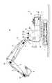
最初に、図1を参照し、本発明の実施例に係る建設機械としてのショベル(掘削機)50について説明する。なお、図1は、本実施例に係るショベルの側面図である。ショベル50の下部走行体1には、旋回機構2を介して上部旋回体3が搭載される。上部旋回体3には、ブーム4が取り付けられる。ブーム4の先端にはアーム5が取り付けられ、アーム5の先端にはエンドアタッチメントとしてのバケット6が取り付けられる。 First, the excavator (excavator) 50 as a construction machine according to the embodiment of the present invention will be described with reference to FIG. Note that FIG. 1 is a side view of the excavator according to this embodiment. The upper
アタッチメントの一例である掘削アタッチメントを構成する作業要素としてのブーム4、アーム5、及びバケット6は、ブームシリンダ7、アームシリンダ8、及びバケットシリンダ9によりそれぞれ油圧駆動される。 The
ブーム4にはブーム角度センサS1が取り付けられ、アーム5にはアーム角度センサS2が取り付けられ、バケット6にはバケット角度センサS3が取り付けられている。ブーム角度センサS1、アーム角度センサS2、及びバケット角度センサS3を集合的に「姿勢センサ」と称する。 A boom angle sensor S1 is attached to the
ブーム角度センサS1は、ブーム4の回動角度を検出する。ブーム角度センサS1は、例えば、水平面に対するブーム4の傾斜を検出することで上部旋回体3に対するブーム4の回動角度を検出する加速度センサである。 The boom angle sensor S1 detects the rotation angle of the
アーム角度センサS2は、アーム5の回動角度を検出する。アーム角度センサS2は、例えば、水平面に対するアーム5の傾斜を検出することでブーム4に対するアーム5の回動角度を検出する加速度センサである。 The arm angle sensor S2 detects the rotation angle of the arm 5. The arm angle sensor S2 is, for example, an acceleration sensor that detects the rotation angle of the arm 5 with respect to the
バケット角度センサS3は、バケット6の回動角度を検出する。バケット角度センサS3は、例えば、水平面に対するバケット6の傾斜を検出することでアーム5に対するバケット6の回動角度を検出する加速度センサである。ブーム角度センサS1、アーム角度センサS2、及びバケット角度センサS3は、可変抵抗器を利用したポテンショメータ、対応する油圧シリンダのストローク量を検出するストロークセンサ、連結ピン回りの回動角度を検出するロータリエンコーダ等であってもよい。 The bucket angle sensor S3 detects the rotation angle of the bucket 6. The bucket angle sensor S3 is, for example, an acceleration sensor that detects the rotation angle of the bucket 6 with respect to the arm 5 by detecting the inclination of the bucket 6 with respect to the horizontal plane. The boom angle sensor S1, the arm angle sensor S2, and the bucket angle sensor S3 are a potentiometer using a variable resistor, a stroke sensor that detects the stroke amount of the corresponding hydraulic cylinder, and a rotary encoder that detects the rotation angle around the connecting pin. And so on.
歪みセンサS4は、アタッチメントの歪みを検出する。本実施例では、歪みセンサS4はブーム4の表面に取り付けられてブーム4の伸張又は圧縮による歪みを検出する1軸歪みゲージである。但し、歪みセンサS4は、3軸歪みゲージであってもよく、アタッチメントの複数箇所に取り付けられる複数の1軸歪みゲージであってもよく、複数の3軸歪みゲージであってもよく、1又は複数の1軸歪みゲージと1又は複数の3軸歪みゲージの組み合わせであってもよい。 The strain sensor S4 detects the distortion of the attachment. In this embodiment, the strain sensor S4 is a uniaxial strain gauge attached to the surface of the
上部旋回体3には、キャビン10が設けられ、エンジン11等の動力源及び車体傾斜センサS5が搭載される。キャビン10内には、コントローラ30、入力装置D1、音声出力装置D2、表示装置D3、記憶装置D4、及びエンジンコントローラD6が設けられ、キャビン10の外には通信装置D5が設けられている。 The
車体傾斜センサS5は、ショベル50の車体の傾斜角度を検出する。本実施例では、車体傾斜センサS5は、水平面に対する車体の傾斜角度を検出する加速度センサである。車体の傾斜角度は、例えば、ブーム4の上下左右の面に取り付けられた歪みゲージの出力から導き出されてもよい。この場合、車体傾斜センサS5は省略されてもよい。 The vehicle body tilt sensor S5 detects the tilt angle of the vehicle body of the
コントローラ30は、ショベル50の駆動制御を行う主制御部として機能する制御装置である。コントローラ30は、CPU及び内部メモリを含む演算処理装置で構成されている。コントローラ30の各種機能は、CPUが内部メモリに格納されているプログラムを実行することで実現される。 The
入力装置D1は、ショベル50の操作者がコントローラ30に各種情報を入力するための装置である。入力装置D1は、例えば、表示装置D3の表面に設けられるメンブレンスイッチを含む。また、入力装置D1は、タッチパネル等であってもよい。 The input device D1 is a device for the operator of the
音声出力装置D2は、コントローラ30からの指令に応じて各種音声情報を出力する。音声出力装置D2は、例えば、コントローラ30に接続される車載スピーカである。また、音声出力装置D2は、ブザー等の警報器であってもよい。 The voice output device D2 outputs various voice information in response to a command from the
表示装置D3は、コントローラ30からの指令に応じて各種情報を含む画面を表示する。表示装置D3は、例えば、コントローラ30に接続される車載液晶ディスプレイである。 The display device D3 displays a screen including various information in response to a command from the
記憶装置D4は、各種情報を記憶するための装置である。記憶装置D4は、例えば、半導体メモリ等の不揮発性記憶媒体である。本実施例では、記憶装置D4は、ブーム角度センサS1、アーム角度センサS2、バケット角度センサS3、歪みセンサS4、車体傾斜センサS5等の検出値、コントローラ30の出力値等を記憶する。 The storage device D4 is a device for storing various types of information. The storage device D4 is, for example, a non-volatile storage medium such as a semiconductor memory. In this embodiment, the storage device D4 stores the detection values of the boom angle sensor S1, the arm angle sensor S2, the bucket angle sensor S3, the strain sensor S4, the vehicle body inclination sensor S5, and the like, and the output value of the
通信装置D5は、コントローラ30とショベル50の外部にある装置との無線通信を制御する装置である。 The communication device D5 is a device that controls wireless communication between the
エンジンコントローラD6はエンジン11を制御する装置である。本実施例では、エンジンコントローラD6は燃料噴射量等を制御してエンジン11を所定のエンジン回転数で維持するアイソクロナス制御を実行する。 The engine controller D6 is a device that controls the
図2は、ショベル50に搭載される駆動系の構成例を示す図であり、機械駆動系、高圧油圧ライン、パイロットライン、及び電気制御系をそれぞれ二重線、実線、破線、及び点線で示す。 FIG. 2 is a diagram showing a configuration example of a drive system mounted on the
ショベル50の駆動系は、主に、エンジン11、メインポンプ14L、14R、パイロットポンプ15、コントロールバルブ17、操作装置26、圧力センサ29、及びコントローラ30を含む。 The drive system of the
エンジン11は、例えば、所定の回転数を維持するように動作するディーゼルエンジンである。また、エンジン11の出力軸は、メインポンプ14L、14R及びパイロットポンプ15の入力軸に接続される。 The
メインポンプ14L、14Rは、高圧油圧ラインを介して作動油をコントロールバルブ17に供給するための装置であり、例えば、斜板式可変容量型油圧ポンプである。 The
パイロットポンプ15は、パイロットライン25を介して操作装置26を含む各種油圧制御機器に作動油を供給するための装置であり、例えば、固定容量型油圧ポンプである。 The
コントロールバルブ17は、ショベル50における油圧系を制御する油圧制御装置である。具体的には、コントロールバルブ17は、メインポンプ14L、14Rが吐出する作動油の流れを制御する流量制御弁171〜176を含む。そして、コントロールバルブ17は、流量制御弁171〜176を通じ、ブームシリンダ7、アームシリンダ8、バケットシリンダ9、左側走行用油圧モータ1A、右側走行用油圧モータ1B、及び旋回用油圧モータ2Aのうちの1又は複数のものに対しメインポンプ14L、14Rが吐出する作動油を選択的に供給する。なお、以下では、ブームシリンダ7、アームシリンダ8、バケットシリンダ9、左側走行用油圧モータ1A、右側走行用油圧モータ1B、及び旋回用油圧モータ2Aを集合的に「油圧アクチュエータ」と称する。 The
操作装置26は、操作者が油圧アクチュエータの操作のために用いる装置である。本実施例では、操作装置26は、パイロットライン25を介して、パイロットポンプ15が吐出する作動油を油圧アクチュエータのそれぞれに対応する流量制御弁のパイロットポートに供給する。なお、パイロットポートのそれぞれに供給される作動油の圧力(パイロット圧)は、油圧アクチュエータのそれぞれに対応する操作装置26のレバー又はペダルの操作方向及び操作量に応じた圧力である。 The operating
圧力センサ29は、操作装置26を用いた操作者の操作内容を検出するための操作内容検出部の一例である。本実施例では、圧力センサ29は、油圧アクチュエータのそれぞれに対応する操作装置26のレバー又はペダルの操作方向及び操作量を圧力の形で検出し、検出した値をコントローラ30に対して出力する。なお、操作装置26の操作内容は、ポテンショメータ等、圧力センサ以外の他のセンサの出力を用いて導き出されてもよい。 The
センターバイパス管路40Lは、コントロールバルブ17内に配置された流量制御弁171、173、及び175を通る高圧油圧ラインであり、センターバイパス管路40Rは、コントロールバルブ17内に配置された流量制御弁172、174、及び176を通る高圧油圧ラインである。 The
流量制御弁171は、メインポンプ14L、左側走行用油圧モータ1A、及び作動油タンクの間の作動油の流量及び流れ方向を制御するスプール弁である。また、流量制御弁172は、メインポンプ14R、右側走行用油圧モータ1B、及び作動油タンクの間の作動油の流量及び流れ方向を制御するスプール弁である。また、流量制御弁173は、メインポンプ14L、旋回用油圧モータ2A、及び作動油タンクの間の作動油の流量及び流れ方向を制御するスプール弁である。 The flow
流量制御弁174は、メインポンプ14R、バケットシリンダ9、及び作動油タンクの間の作動油の流量及び流れ方向を制御するスプール弁である。また、流量制御弁175は、メインポンプ14L、アームシリンダ8、及び作動油タンクの間の作動油の流量及び流れ方向を制御するスプール弁である。また、流量制御弁176は、メインポンプ14R、ブームシリンダ7、及び作動油タンクの間の作動油の流量及び流れ方向を制御するスプール弁である。 The flow
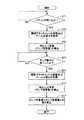
次に、図3を参照しながらショベル50の動作の一例である掘削・積み込み動作について説明する。まず、図3(A)に示すように、操作者は、アーム5及びバケット6が開いた状態でバケット6の先端が掘削対象から所望の高さとなるように上部旋回体3を旋回させ且つバケット6を下降させる。上部旋回体3を旋回させる際、及び、ブーム4を下降させる際、操作者は目視でバケット6の位置を確認する。上部旋回体3の旋回、及び、ブーム4の下降は同時に行われることが一般的である。以上の動作をブーム下げ旋回動作と称し、この動作区間をブーム下げ旋回動作区間と称する。 Next, the excavation / loading operation, which is an example of the operation of the
操作者は、バケット6の先端が所望の高さに到達したと判断した場合、図3(B)に示すように、アーム5が地面に対して略垂直になるまでアーム5を閉じる。これにより、所定の深さの土が掘削され、アーム5が地表面に対して略垂直になるまで、バケット6でかき寄せられる。次に、操作者は、図3(C)に示すように、アーム5及びバケット6を更に閉じ、図3(D)に示すように、バケット6がアーム5に対して略垂直になるまでバケット6を閉じる。すなわち、バケット6の上縁が略水平となるまでバケット6を閉じ、かき集めた土をバケット6内に収容する。以上の動作を掘削動作と称し、この動作区間を掘削動作区間と称する。 When the operator determines that the tip of the bucket 6 has reached a desired height, the operator closes the arm 5 until the arm 5 is substantially perpendicular to the ground, as shown in FIG. 3 (B). As a result, soil of a predetermined depth is excavated and the arm 5 is scraped by the bucket 6 until it is substantially perpendicular to the ground surface. Next, the operator further closes the arm 5 and the bucket 6 as shown in FIG. 3C, and buckets until the bucket 6 is substantially perpendicular to the arm 5 as shown in FIG. 3D. Close 6 That is, the bucket 6 is closed until the upper edge of the bucket 6 is substantially horizontal, and the collected soil is stored in the bucket 6. The above operation is referred to as an excavation operation, and this operation section is referred to as an excavation operation section.
次に、操作者は、バケット6がアーム5に対して略垂直になるまで閉じたと判断した場合、図3(E)に示すように、バケット6を閉じたままバケット6の底部が地面から所望の高さとなるまでブーム4を上げる。この動作をブーム上げ動作と称し、この動作区間をブーム上げ動作区間と称する。この動作に続いて、或いは同時に、操作者は、上部旋回体3を旋回させ、矢印AR1で示すようにバケット6を排土位置まで旋回移動する。ブーム上げ動作を含むこの動作をブーム上げ旋回動作と称し、この動作区間をブーム上げ旋回動作区間と称する。 Next, when the operator determines that the bucket 6 is closed until it is substantially perpendicular to the arm 5, the bottom of the bucket 6 is desired from the ground while the bucket 6 is closed, as shown in FIG. 3 (E). Raise the
バケット6の底部が所望の高さとなるまでブーム4を上げるのは、例えば、ダンプトラックの荷台に排土する際にはバケット6を荷台の高さより高く持ち上げないとバケット6が荷台にぶつかってしまうためである。 Raising the
次に、操作者は、ブーム上げ旋回動作が完了したと判断した場合、図3(F)に示すようにアーム5及びバケット6を開いて、バケット6内の土を排出する。この動作をダンプ動作と称し、この動作区間をダンプ動作区間と称する。ダンプ動作では、バケット6のみを開いて排土してもよい。 Next, when the operator determines that the boom raising and turning operation is completed, the arm 5 and the bucket 6 are opened as shown in FIG. 3 (F), and the soil in the bucket 6 is discharged. This operation is referred to as a dump operation, and this operation section is referred to as a dump operation section. In the dump operation, only the bucket 6 may be opened and the soil may be discharged.
次に、操作者は、ダンプ動作が完了したと判断した場合、図3(G)に示すように、矢印AR2で示すように上部旋回体3を旋回させ、バケット6を掘削位置の真上に移動させる。このとき、旋回と同時にブーム4を下げてバケット6を掘削対象から所望の高さのところまで下降させる。この動作は図3(A)にて説明したブーム下げ旋回動作の一部である。操作者は、図3(A)に示すようにバケット6を所望の高さまで下降させ、再び掘削動作以降の動作を行うようにする。 Next, when the operator determines that the dump operation is completed, as shown in FIG. 3 (G), the
操作者は、上述の「ブーム下げ旋回動作」、「掘削動作」、「ブーム上げ旋回動作」、及び「ダンプ動作」を1サイクルとしてこのサイクルを繰り返し行いながら掘削・積み込みを進めていく。 The operator proceeds with excavation and loading while repeating this cycle with the above-mentioned "boom lowering turning operation", "excavation operation", "boom raising turning operation", and "dump operation" as one cycle.
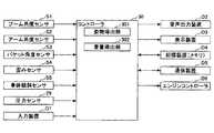
次に図4を参照し、コントローラ30に設けられている各種機能について説明する。図4は、コントローラ30の構成例を示す図である。 Next, with reference to FIG. 4, various functions provided in the
コントローラ30は、ブーム角度センサS1、アーム角度センサS2、バケット角度センサS3、歪みセンサS4、車体傾斜センサS5、入力装置D1、圧力センサ29等から情報を受信する。 The
コントローラ30は、受信した情報と記憶装置D4に記憶された情報とに基づいて各種演算を実行し、その演算結果に応じて制御信号を音声出力装置D2、表示装置D3、エンジンコントローラD6等に出力する。また、コントローラ30は、通信装置D5を介して受信した情報、演算結果等を外部に無線送信してもよい。 The
姿勢導出部301は、アタッチメントの姿勢を検出する機能要素である。本実施例では、姿勢導出部301は、ブーム角度センサS1、アーム角度センサS2、及びバケット角度センサS3で構成される姿勢センサの出力に基づいて掘削アタッチメントの姿勢を導き出す。 The
重量導出部302は、アタッチメントが持ち上げている物の重量(以下、「持ち上げ重量」とする。)を導き出す機能要素である。本実施例では、重量導出部302は、所定の導出条件が満たされた場合に、姿勢センサが検出した掘削アタッチメントの姿勢と歪みセンサS4が検出した掘削アタッチメントの歪みとに基づいて持ち上げ重量を導き出す。 The
例えば、重量導出部302は、掘削アタッチメントの歪み、掘削アタッチメントの姿勢、掘削アタッチメントの形状、歪みゲージの貼り付け位置等を入力キーとして対応テーブルを参照することで持ち上げ重量を導き出す。対応テーブルは、掘削アタッチメントの姿勢と、掘削アタッチメントの歪みと、持ち上げ重量との対応関係を記憶する参照用テーブルであり、記憶装置D4に予め記憶されている。対応関係はFEM解析等に基づいて予め決定されている。例えば、重量導出部302は、現在の掘削アタッチメントの姿勢と歪みの組み合わせに最も近い組み合わせを対応テーブルの中から選択し、その選択した組み合わせに関連付けて記憶されている持ち上げ重量の値を現在の持ち上げ重量として導き出す。掘削アタッチメントの歪みは、掘削アタッチメントにおける1又は複数の部位における歪みを意味する。 For example, the
或いは、重量導出部302は、掘削アタッチメントの歪みと掘削アタッチメントの姿勢とを予め記憶された計算式に代入することで持ち上げ重量を導き出してもよい。計算式は記憶装置D4に予め記憶されている。 Alternatively, the
「所定の導出条件」は、重量導出部302が重量を導き出すタイミングを決めるための条件であり、例えば、「バケット6が浮いたこと」(第1の導出条件)及び「ダンプ動作が完了したこと」(第2の導出条件)を含む。「バケット6が浮いたこと」すなわちバケット6が地面から離れたことを第1の導出条件とするのは、バケット6が浮いたときにはバケット6内に土砂等の物が収まっていると推定できるためである。「ダンプ動作が完了したこと」を第2の導出条件とするのは、ダンプ動作が完了したときにはバケット6内が空になっている、或いは、落とせる土砂を落としきったと推定できるためである。 The "predetermined derivation condition" is a condition for determining the timing at which the
コントローラ30は、例えば、掘削動作後に旋回操作が行われたと判定した場合に第1の導出条件が満たされたと判定する。旋回操作が行われるときにはバケット6が空中に浮いていると推定できるためである。「掘削動作後」は図3(D)の動作後にあたり、コントローラ30は、掘削アタッチメントの姿勢と、ブーム4の上下面に取り付けた歪みゲージが検出した掘削アタッチメントの歪みから、掘削動作後の状態にあるか否かを判定できる。具体的には、コントローラ30は、掘削動作後に圧力センサ29の出力に基づいて旋回操作レバーが操作されたと判定した場合に第1の導出条件が満たされたと判定する。コントローラ30は、ブーム4の両側面のそれぞれに取り付けられた2つの歪みゲージの出力に基づいて旋回操作が行われたか否かを判定してもよい。 The
或いは、コントローラ30は、ブーム4が所定の高さ以上に上昇したと判定した場合に第1の導出条件が満たされたと判定してもよい。ブーム4が所定の高さ以上に上昇したときにはバケット6が空中に浮いていると推定できるためである。具体的には、コントローラ30は、ブーム角度センサS1の出力に基づいてブーム4が所定の高さ以上に上昇したと判定した場合に第1の導出条件が満たされたと判定する。 Alternatively, the
或いは、コントローラ30は、バケット6が所定角度まで閉じられたと判定した場合に第1の導出条件が満たされたと判定してもよい。バケット6が所定角度まで閉じられたときにはバケット6が空中に浮いていると推定できるためである。具体的には、コントローラ30は、バケット角度センサS3の出力に基づいてバケット6が所定角度まで閉じられたと判定した場合に第1の導出条件が満たされたと判定する。 Alternatively, the
また、コントローラ30は、例えば、ダンプ動作中に旋回操作が行われたと判定した場合に第2の導出条件が満たされたと判定する。旋回操作が行われるときにはダンプ動作が完了したと推定できるためである。具体的には、コントローラ30は、ダンプ動作中に圧力センサ29の出力に基づいて旋回操作レバーが操作されたと判定した場合に第2の導出条件が満たされたと判定する。 Further, the
或いは、コントローラ30は、第1の導出条件が満たされた後に、バケット6が所定角度まで開かれたと判定した場合に第2の導出条件が満たされたと判定してもよい。バケット6が所定角度まで開かれたときにはダンプ動作が完了したと推定できるためである。具体的には、コントローラ30は、バケット角度センサS3の出力に基づいてバケット6が所定角度まで開かれたと判定した場合に第2の導出条件が満たされたと判定する。 Alternatively, the
重量導出部302は、持ち上げ重量を導き出した場合、その導出結果に応じて音声出力装置D2、表示装置D3、通信装置D5、及びエンジンコントローラD6の少なくとも1つに制御指令を出力してもよい。例えば、重量導出部302は、持ち上げ重量に関する情報を表示装置D3に表示してもよく、音声出力装置D2を通じて音声出力してもよい。また、重量導出部302は、通信装置D5を介して持ち上げ重量に関する情報を外部に無線送信してもよい。また、持ち上げ重量が所定値以上の場合に、エンジンコントローラD6を介してエンジン11の出力を増大させてもよい。 When the
姿勢導出部301及び重量導出部302はショベルの外部にある外部制御装置によって実現されてもよい。外部制御装置は、コントローラ30と同様、CPU及び内部メモリを含む演算処理装置である。この場合、コントローラ30は、取得した情報を通信装置D5を通じて外部制御装置に無線送信する。 The attitude lead-out
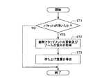
次に図5を参照し、コントローラ30が持ち上げ重量を導き出す処理(以下、「重量導出処理」とする。)について説明する。図5は重量導出処理の流れを示すフローチャートである。コントローラ30は、所定の制御周期で繰り返しこの重量導出処理を実行する。 Next, with reference to FIG. 5, a process in which the
最初に、コントローラ30の重量導出部302はバケット6が浮いたか否かを判定する(ステップST1)。本実施例では、重量導出部302は、掘削動作後に旋回操作が行われた場合にバケット6が浮いたと判定する。重量導出部302は、油圧シリンダにおける作動油の圧力に基づいてバケット6が浮いたか否かを判定してもよい。また、重量導出部302は、ブーム操作レバーが上げ方向に操作されてから所定時間(例えば2秒間)が経過した後で旋回操作レバーが操作される前にバケット6が浮いたか否かを判定してもよい。旋回が始まると旋回慣性力による歪みがノイズとして作用するためである。 First, the
バケット6が浮いていないと判定した場合(ステップST1のNO)、重量導出部302は、バケット6が浮いたと判定するまでバケット6が浮いたか否かの判定を繰り返す。 When it is determined that the bucket 6 is not floating (NO in step ST1), the
バケット6が浮いたと判定した場合(ステップST1のYES)、重量導出部302は、掘削アタッチメントの姿勢及びブーム4の歪みを取得する(ステップST2)。本実施例では、重量導出部302は、姿勢センサの出力に基づいて姿勢導出部301が導き出した掘削アタッチメントの姿勢を取得する。また、歪みセンサS4の出力に基づいてブーム4の歪みを取得する。 When it is determined that the bucket 6 has floated (YES in step ST1), the
その後、重量導出部302は持ち上げ重量を導き出す(ステップST3)。本実施例では、掘削アタッチメントの姿勢とブーム4の歪みとを入力キーとして記憶装置D4に記憶されている対応テーブルを参照することでバケット6内に取り込まれた土砂等の重量を持ち上げ重量として導き出す。 After that, the
この構成により、コントローラ30は、例えば、ダンプトラックに積み込まれた土砂等の積み込み重量(=持ち上げ重量)を掘削・積み込みの1サイクル毎に導き出すことができる。また、サイクル毎の積み込み重量をダンプトラック毎に累算することで1台のダンプトラックに積み込まれた土砂の総積載重量を作業量として導き出すことができる。また、コントローラ30は所定時間に亘ってサイクル毎の持ち上げ重量を累算することで所定時間当たりの掘削重量を作業量として導き出すことができる。そのため、コントローラ30は掘削アタッチメントによる作業量をより高精度に導き出すことができる。 With this configuration, the
本実施例では、コントローラ30は、バケット6が浮いたと判定した時点の掘削アタッチメントの姿勢と歪みセンサS4の出力とに基づいて持ち上げ重量を導き出す。しかしながら、コントローラ30は、1サイクル中においてバケット6が浮いたと判定した後の複数の時点における掘削アタッチメントの姿勢と歪みセンサS4の出力とに基づいて持ち上げ重量を導き出してもよい。この場合、コントローラ30は、バケット6が浮いたと判定した後の複数の時点において導き出された複数の持ち上げ重量の統計値(平均値、最大値、最小値、中間値等)を最終的な持ち上げ重量として出力してもよい。 In this embodiment, the
また、コントローラ30は、バケット6が浮いたか否かにかかわらず、掘削アタッチメントの姿勢とブーム4の歪みとを継続的に取得しながら持ち上げ重量を継続的に導き出してもよい。この場合も、コントローラ30は、バケット6が浮いたと判定した時点の持ち上げ重量、又は、バケット6が浮いたと判定した後の複数の時点における持ち上げ重量の統計値を最終的な持ち上げ重量として出力してもよい。 Further, the
また、コントローラ30は、掘削アタッチメントの姿勢の変化に基づき、掘削作業、法面形成作業、床掘り作業といった作業内容を判別してもよい。この場合、コントローラ30は、識別した作業内容とその後に導き出した作業量とを関連付け、作業内容毎に作業量を導き出してもよい。 Further, the
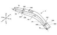
次に図6及び図7を参照し、ブーム4における歪みセンサS4の取り付け位置について説明する。図6及び図7は何れもブーム4の斜視図であり、ブーム4に取り付けられた歪みセンサの配置を示す。 Next, the mounting position of the strain sensor S4 on the
図6に示す実施例では、歪みセンサS4としての歪みゲージS40は、ブーム4の長手方向(掘削アタッチメントの前後方向)におけるブーム4の歪みを検出するように、ブームシリンダボス4aとブームフート4bとの間でブーム4の背側(+Z側)の表面に取り付けられている。具体的には、歪みゲージS40は、ブーム4の背側の表面の中央部分に取り付けられている。すなわちブーム4の縦中心面(一点鎖線で示す線分を含みブーム4を縦断する面)を横切るように配置されている。但し、歪みゲージS40は、ブーム4の腹側(−Z側)の表面に取り付けられていてもよく、ブームシリンダボス4aとブームトップ4cとの間でブーム4の背側又は腹側の表面に取り付けられていてもよい。また、中央部分以外の部分に取り付けられてもよい。歪みセンサS4は、背面又は腹面に貼り付けられる場合であっても、ブーム4の長手方向における引張圧縮応力を算出できるように貼り付けられる。 In the embodiment shown in FIG. 6, the strain gauge S40 as the strain sensor S4 has the
この配置により、歪みセンサS4は、例えば、掘削アタッチメントで土砂等を持ち上げるときのブーム4の背側及び腹側の金属板の伸縮による歪みを検出できる。また、掘削アタッチメント(ブーム4)に作用する持ち上げ荷重に起因する引張圧縮応力による歪みを検出できる。また、歪みセンサS4は、ブーム4の表面ではなく、背側又は腹側の内部に貼り付けられていてもよい。この構成は、ショベルのような掘削作業を行う機械であっても、歪みセンサS4の損傷を防止できる。 With this arrangement, the strain sensor S4 can detect, for example, strain due to expansion and contraction of the metal plates on the dorsal and ventral sides of the
図7に示す実施例では、歪みセンサS4は8個の歪みゲージS41〜S48で構成されている。図7の破線は隠れ線を表す。歪みゲージS41及び歪みゲージS42は3軸歪みゲージである。歪みゲージS43〜S48は1軸歪みゲージである。歪みゲージS41〜S44は、ブームシリンダボス4aとブームフート4bとの間でブーム4の背側(+Z側)、腹側(−Z側)、左側(−Y側)、右側(+Y側)の表面に取り付けられている。歪みゲージS45〜S48は、ブームシリンダボス4aとブームトップ4cとの間でブーム4の背側(+Z側)、腹側(−Z側)、左側(−Y側)、右側(+Y側)の表面に取り付けられている。歪みゲージS41、S42、S45、S46はブーム4の縦中心面を横切るように配置されている。歪みゲージS43、S44、S47、S48は、ブーム4の左側又は右側の表面の中央部分に、ブーム4の長手方向における引張圧縮応力を算出できるように、貼り付けられている。すなわちブーム4の横中心面(二点鎖線で示す線分を含みブーム4を横断する面)を横切るように配置されている。また、歪みゲージS41〜S44は一点鎖線で示す仮想平面としての後方基準断面R1を横切るように配置され、歪みゲージS45〜S48は一点鎖線で示す仮想平面としての前方基準断面R2上を横切るように配置されている。後方基準断面R1及び前方基準断面R2は図6の一点鎖線で表される線分及び図7の二点鎖線で表される線分のそれぞれに垂直である。 In the embodiment shown in FIG. 7, the strain sensor S4 is composed of eight strain gauges S41 to S48. The broken line in FIG. 7 represents a hidden line. The strain gauge S41 and the strain gauge S42 are triaxial strain gauges. Strain gauges S43 to S48 are uniaxial strain gauges. The strain gauges S41 to S44 are the surfaces of the
また、図7の実施例では、8個の歪みゲージの全てがブーム4の表面に取り付けられているが、歪みゲージは8個未満でも9個以上であってもよく、ブーム4の表面以外の位置に取り付けられてもよい。例えば、全ての歪みゲージがアーム5の表面に取り付けられてもよい。また、ブーム4の表面及びアーム5の表面に分散して取り付けられてもよい。また、歪みゲージは、ブーム4、アーム5等の作業要素の表面ではなく、作業要素の内部に貼り付けられていてもよい。 Further, in the embodiment of FIG. 7, all eight strain gauges are attached to the surface of the
図7の実施例は、8個の歪みゲージS41〜S48を用いるため、1個の歪みゲージを用いる図6の実施例よりも掘削アタッチメントの歪み状態を高精度に検出できる。そのため、掘削アタッチメントが動作中であっても掘削アタッチメントの歪み状態を高精度に検出できる。 Since the embodiment of FIG. 7 uses eight strain gauges S41 to S48, the strain state of the excavation attachment can be detected with higher accuracy than the embodiment of FIG. 6 using one strain gauge. Therefore, even when the excavation attachment is in operation, the distorted state of the excavation attachment can be detected with high accuracy.
次に図8を参照し、重量導出処理の別の一例について説明する。図8は重量導出処理の別の流れを示すフローチャートである。コントローラ30は、所定の制御周期で繰り返しこの重量導出処理を実行する。 Next, another example of the weight derivation process will be described with reference to FIG. FIG. 8 is a flowchart showing another flow of the weight derivation process. The
最初に、コントローラ30の重量導出部302はバケット6が浮いたか否かを判定する(ステップST1)。本実施例では、重量導出部302は、掘削動作後に旋回操作が行われた場合にバケット6が浮いたと判定する。 First, the
バケット6が浮いていないと判定した場合(ステップST1のNO)、重量導出部302は、バケット6が浮いたと判定するまでバケット6が浮いたか否かの判定を繰り返す。 When it is determined that the bucket 6 is not floating (NO in step ST1), the
バケット6が浮いたと判定した場合(ステップST1のYES)、重量導出部302は、掘削アタッチメントの姿勢及びブーム4の歪みを取得する(ステップST2)。本実施例では、重量導出部302は、姿勢センサの出力に基づいて姿勢導出部301が導き出した掘削アタッチメントの姿勢を取得する。また、歪みセンサS4の出力に基づいてブーム4の歪みを取得する。 When it is determined that the bucket 6 has floated (YES in step ST1), the
その後、重量導出部302は持ち上げ重量(ダンプ前重量)を導き出す(ステップST3)。本実施例では、掘削アタッチメントの姿勢とブーム4の歪みとを入力キーとして記憶装置D4に記憶されている対応テーブルを参照することでバケット6内に取り込まれた土砂等の重量を持ち上げ重量(ダンプ前重量)として導き出す。 After that, the
その後、重量導出部302はダンプ動作が完了したか否かを判定する(ステップST4)。本実施例では、重量導出部302は、ダンプ動作中に旋回操作が行われた場合にダンプ動作が完了したと判定する。重量導出部302は、油圧シリンダにおける作動油の圧力、姿勢センサの出力等に基づいてダンプ動作が完了したか否かを判定してもよい。また、重量導出部302は、ショベルに搭載されたカメラが撮像した画像に基づいて掘削アタッチメントがダンプトラックの方向を向いていると判定した場合にダンプ動作の開始を検出してもよい。また、その画像に基づいてバケット6がダンプトラックの真上に位置していると判定した場合にダンプ動作の開始を検出してもよい。その上で、圧力センサ29の出力に基づいてバケット操作レバーが開き方向に操作されたと判定した場合、或いは、バケット角度センサの出力に基づいてバケット6が開かれたと判定した場合にダンプ動作が完了したと判定してもよい。 After that, the
ダンプ動作が完了していないと判定した場合(ステップST4のNO)、重量導出部302は、ダンプ動作が完了したと判定するまでダンプ動作が完了したか否かの判定を繰り返す。 When it is determined that the dump operation is not completed (NO in step ST4), the
ダンプ動作が完了したと判定した場合(ステップST4のYES)、重量導出部302は、掘削アタッチメントの姿勢及びブーム4の歪みを取得する(ステップST5)。本実施例では、重量導出部302は、姿勢センサの出力に基づいて姿勢導出部301が導き出した掘削アタッチメントの姿勢を取得する。また、歪みセンサS4の出力に基づいてブーム4の歪みを取得する。 When it is determined that the dump operation is completed (YES in step ST4), the
その後、重量導出部302は持ち上げ重量(ダンプ後重量)を導き出す(ステップST6)。本実施例では、掘削アタッチメントの姿勢とブーム4の歪みとを入力キーとして記憶装置D4に記憶されている対応テーブルを参照することでダンプ動作後にバケット6内に残っている土砂等の重量を持ち上げ重量(ダンプ後重量)として導き出す。 After that, the
その後、重量導出部302はダンプ前重量とダンプ後重量との差を算出する(ステップST7)。そして、重量導出部302はその差をダンプトラックに積み込まれた土砂等の積み込み重量とする。 After that, the
この構成により、コントローラ30は、例えば、ダンプトラックに積み込まれた土砂等の積み込み重量を掘削・積み込みの1サイクル毎に導き出すことができる。また、サイクル毎の積み込み重量を累算することでダンプトラックに積み込まれた土砂の総重量を導き出すことができる。また、ダンプ前重量とダンプ後重量との差を積み込み重量とするため、例えばダンプ動作の完了時にバケット6の内側に張り付いている土砂等の重量が積み込み重量に含まれてしまうのを防止できる。 With this configuration, the
次に図9を参照し、掘削アタッチメントに作用するねじり荷重について説明する。図9は、鉛直軸に対して角度θだけ傾斜したショベル50の掘削アタッチメントの正面図である。鉛直下方を向く矢印G1は、バケット6及びバケット6内に取り込まれた土砂等の重心に作用する重力を示す。バケット6の幅方向を向く矢印G1aはその重力の幅方向における成分である横力を示す。 Next, with reference to FIG. 9, the torsional load acting on the excavation attachment will be described. FIG. 9 is a front view of the excavator attachment of the
この横力の存在により、ショベル50の車体が傾斜している場合、アーム5はアーム5とブーム4との連結部を中心として回転しようとし、ブーム4に作用するねじり荷重T1を発生させてしまう。 Due to the presence of this lateral force, when the vehicle body of the
図9に示す実施例では、歪みセンサS4としての歪みゲージS40は、3軸歪みゲージであり、ブーム4の内部に貼り付けられている。3軸歪みゲージを用いることで、コントローラ30は、X軸方向、Y軸方向、及びZ軸方向の全ての方向における歪みを検出できる。そのため、コントローラ30は、1箇所に貼られたセンサで、各方向に生じる掘削荷重に基づく曲げ応力を算出できるだけでなく、偏心掘削時に生じるねじり荷重に基づくせん断応力も算出できる。また、3軸歪みゲージを用いずに、図7に示したようにブーム4上で各方向(X軸方向、Y軸方向、Z軸方向)に対して歪みゲージが貼り付けられていてもよい。 In the embodiment shown in FIG. 9, the strain gauge S40 as the strain sensor S4 is a triaxial strain gauge, which is attached to the inside of the
ねじり荷重T1は、歪みゲージS40の出力によって形成される特定のパターンをもたらす。コントローラ30は、この特定のパターンを検知することによってねじり荷重T1が発生していることを検知できる。これにより、部品寿命を精度良く算出できる。 The torsional load T1 results in a particular pattern formed by the output of the strain gauge S40. The
また、3軸歪みゲージをアーム5の表面に取り付けてもよい。この場合、コントローラ30は、アーム5に作用するねじり荷重によるせん断応力を算出できるので、アーム5の寿命を精度良く算出できる。 Further, a 3-axis strain gauge may be attached to the surface of the arm 5. In this case, since the
次に図10を参照し、ショベル50が接続される通信ネットワーク100について説明する。図10は、ショベル50が接続される通信ネットワーク100を示す概略図である。通信ネットワーク100は、主に、ショベル50、基地局21、サーバ22、及び通信端末23で構成される。通信端末23は、携帯通信端末23a、固定通信端末23b等を含む。基地局21、サーバ22、及び通信端末23は、それぞれ、インターネットプロトコル等の通信プロトコルを用いて互いに接続され得る。なお、ショベル50、基地局21、サーバ22、及び通信端末23のそれぞれは1つであってもよく複数であってもよい。また、携帯通信端末23aは、ノートパソコン、携帯電話、スマートフォン等を含む。 Next, with reference to FIG. 10, the
基地局21は、ショベル50が無線送信する情報を受信する固定施設であり、例えば、衛星通信、携帯電話通信、狭域無線通信等を通じてショベル50との間で情報を送受信する。 The
サーバ22は、ショベル50が無線送信する情報を保存し且つ管理する装置であり、例えば、CPU、ROM、RAM、入出力インタフェース等を備えたコンピュータである。具体的には、サーバ22は、通信ネットワーク100を通じて、基地局21が受信した情報を取得・保存し、操作者(管理者)が必要に応じてその保存した情報を参照できるように管理する。 The
また、サーバ22は、通信ネットワーク100を通じてショベル50の各種設定を行う。具体的には、サーバ22は、ショベル50の各種設定に関する値をショベル50に対して無線送信し、ショベル50のコントローラ30に記憶される各種設定に関する値を変更する。 In addition, the
また、サーバ22は、通信ネットワーク100を通じて通信端末23に各種情報を送信する。具体的には、サーバ22は、所定の条件が満たされた場合に、或いは、通信端末23からの要求に応じて、ショベル50に関する情報を通信端末23に対して送信し、ショベル50に関する情報を通信端末23の操作者に伝えるようにする。 Further, the
通信端末23は、サーバ22に保存された情報を参照可能な装置であり、例えば、CPU、ROM、RAM、入出力インタフェース、入力装置、ディスプレイ、スピーカ等を備えたコンピュータである。具体的には、通信端末23は、通信ネットワーク100を通じてサーバ22に接続され、ショベル50に関する情報を操作者(管理者)が閲覧できるようにする。或いは、通信端末23は、サーバ22が送信する、ショベル50に関する情報を受信し、受信した情報を操作者(管理者)が閲覧できるようにする。 The
本実施例では、サーバ22は、ショベル50が無線送信したショベル50の作業量に関する情報を管理する。そのため、操作者(管理者)は、通信端末23を通じてショベル50の作業量に関する情報を任意のタイミングで受信して閲覧することができる。 In this embodiment, the
以上、本発明の好ましい実施例について詳説したが、本発明は、上述した実施例に制限されることはなく、本発明の範囲を逸脱することなしに上述した実施例に種々の変形及び置換を加えることができる。 Although the preferred examples of the present invention have been described in detail above, the present invention is not limited to the above-mentioned examples, and various modifications and substitutions are made to the above-mentioned examples without departing from the scope of the present invention. Can be added.
1・・・下部走行体 1A・・・左側走行用油圧モータ 1B・・・右側走行用油圧モータ 2・・・旋回機構 2A・・・旋回用油圧モータ 3・・・上部旋回体 4・・・ブーム 4a・・・ブームシリンダボス 4b・・・ブームフート 4c・・・ブームトップ 5・・・アーム 6・・・バケット 7・・・ブームシリンダ 8・・・アームシリンダ 9・・・バケットシリンダ 10・・・キャビン 11・・・エンジン 14L、14R・・・メインポンプ 15・・・パイロットポンプ 17・・・コントロールバルブ 21・・・基地局 22・・・サーバ 23・・・通信端末 23a・・・携帯通信端末 23b・・・固定通信端末 25・・・パイロットライン 26・・・操作装置 29・・・圧力センサ 30・・・コントローラ 40L、40R・・・センターバイパス管路 50・・・ショベル 100・・・通信ネットワーク 171〜176・・・流量制御弁 301・・・姿勢導出部 302・・・重量導出部 D1・・・入力装置 D2・・・音声出力装置 D3・・・表示装置 D4・・・記憶装置 D5・・・通信装置 D6・・・エンジンコントローラ S1・・・ブーム角度センサ S2・・・アーム角度センサ S3・・・バケット角度センサ S4・・・歪みセンサ S5・・・車体傾斜センサ S40〜S48・・・歪みゲージ 1 ・ ・ ・ Lower traveling body 1A ・ ・ ・ Hydraulic motor for left side traveling 1B ・ ・ ・ Hydraulic motor for right side traveling 2 ・ ・ ・
Claims (7)
Translated fromJapanese前記下部走行体に搭載される上部旋回体と、
前記上部旋回体に取り付けられ、ブーム、アーム、及びバケットを含むアタッチメントと、
前記アタッチメントのうち、前記ブーム及び前記アームの少なくとも何れかの表面の縦中心面に取り付けられる歪みセンサと、
前記アタッチメントに含まれる前記ブーム、前記アーム、及び前記バケットの全ての姿勢を検出する姿勢センサと、
前記アームを閉じることで前記バケット内に物を収容する掘削動作の後、前記歪みセンサが検出した前記アタッチメントの歪みと、前記姿勢センサが検出した前記アタッチメントの姿勢とに基づいて前記アタッチメントが持ち上げている物の重量を前記バケットが浮いた後に導き出す制御装置と、を有する、
ショベル。With the lower running body,
The upper swivel body mounted on the lower traveling body and
An attachment that is attached to the upper swing body and includes a boom, an arm, and a bucket.
A strain sensor attached tothe vertical center surface of at least one surface of the boom and the arm among the attachments.
A posture sensor that detectsall postures of the boom, the arm, and the bucket included in the attachment, and
After the excavation operation of accommodating an object in the bucket by closing the arm, the attachment is lifted based on the strain of the attachment detected by the strain sensor and the posture of the attachment detected by the posture sensor. It has a control device that derives the weight of an object after the bucket floats.
Excavator.
請求項1に記載のショベル。The control device derives the weight of the object being lifted by the attachment froma plurality of lift weight statistics derived at a plurality of time points after determining that the bucket has floated.
The excavator according to claim 1.
請求項1又は2に記載のショベル。The control device derives the weight of the object lifted by the attachment for each cycle of excavation and loading, and accumulates the weight for each cycle to obtain the total weight of earth and sand loaded on one dump truck. derive,
The excavator according to claim 1 or 2.
請求項1乃至3の何れかに記載のショベル。The strain sensor comprises a strain gauge attached to the laterally central portion of the surface of the boom and at least one of the arms on the side to which the hydraulic cylinder is attached.
The excavator according to any one of claims 1 to 3.
請求項1乃至4の何れかに記載のショベル。The strain sensor includes a 3-axis strain gauge.
The excavator according to any one of claims 1 to 4.
請求項1乃至5の何れかに記載のショベル。The strain sensor includes a strain gauge attached between the boom cylinder boss and the boom foot with respect to the boom constituting the attachment.
The excavator according to any one of claims 1 to 5.
請求項5に記載のショベル。The control device calculates the shear stress caused by the torsional load using the detected value of the triaxial strain gauge.
The excavator according to claim 5.
Priority Applications (1)
| Application Number | Priority Date | Filing Date | Title |
|---|---|---|---|
| JP2016053005AJP6866070B2 (en) | 2016-03-16 | 2016-03-16 | Excavator |
Applications Claiming Priority (1)
| Application Number | Priority Date | Filing Date | Title |
|---|---|---|---|
| JP2016053005AJP6866070B2 (en) | 2016-03-16 | 2016-03-16 | Excavator |
Related Child Applications (1)
| Application Number | Title | Priority Date | Filing Date |
|---|---|---|---|
| JP2020004777ADivisionJP7059309B2 (en) | 2020-01-15 | 2020-01-15 | Excavator and excavator weight calculator |
Publications (2)
| Publication Number | Publication Date |
|---|---|
| JP2017166232A JP2017166232A (en) | 2017-09-21 |
| JP6866070B2true JP6866070B2 (en) | 2021-04-28 |
Family
ID=59909845
Family Applications (1)
| Application Number | Title | Priority Date | Filing Date |
|---|---|---|---|
| JP2016053005AActiveJP6866070B2 (en) | 2016-03-16 | 2016-03-16 | Excavator |
Country Status (1)
| Country | Link |
|---|---|
| JP (1) | JP6866070B2 (en) |
Families Citing this family (13)
| Publication number | Priority date | Publication date | Assignee | Title |
|---|---|---|---|---|
| JP6986853B2 (en)* | 2017-04-28 | 2021-12-22 | 株式会社小松製作所 | Work machine and control method of work machine |
| JP6777613B2 (en)* | 2017-09-26 | 2020-10-28 | 日立建機株式会社 | Transporter stop position direction guidance system |
| JP6970581B2 (en) | 2017-10-04 | 2021-11-24 | 株式会社小松製作所 | Work machines, systems including work machines, and control methods for work machines |
| WO2019182042A1 (en)* | 2018-03-20 | 2019-09-26 | 住友重機械工業株式会社 | Excavator, information processing device, information processing method, and program |
| JP7206985B2 (en)* | 2019-02-08 | 2023-01-18 | コベルコ建機株式会社 | Damage estimation device and machine learning device |
| WO2021085608A1 (en)* | 2019-10-31 | 2021-05-06 | 住友建機株式会社 | Shovel management system, portable terminal for shovel, and program used in portable terminal for shovel |
| JP7268577B2 (en)* | 2019-10-31 | 2023-05-08 | コベルコ建機株式会社 | working machine |
| JP7246294B2 (en)* | 2019-11-26 | 2023-03-27 | コベルコ建機株式会社 | Measuring equipment and construction machinery |
| JP7572797B2 (en)* | 2020-05-29 | 2024-10-24 | 株式会社小松製作所 | Operation system and control method |
| JP7562429B2 (en)* | 2021-01-06 | 2024-10-07 | 日立建機株式会社 | Construction Machinery |
| CN113124972A (en)* | 2021-03-12 | 2021-07-16 | 中国航空工业集团公司西安飞行自动控制研究所 | Excavator material weighing method and system |
| JP2024117921A (en)* | 2023-02-20 | 2024-08-30 | 株式会社小松製作所 | System including a work machine and method for estimating load state of the work machine |
| JP2025033951A (en)* | 2023-08-30 | 2025-03-13 | 株式会社小松製作所 | Soil quality discrimination system and soil quality discrimination method |
Family Cites Families (19)
| Publication number | Priority date | Publication date | Assignee | Title |
|---|---|---|---|---|
| JPS4810962Y1 (en)* | 1969-03-10 | 1973-03-24 | ||
| JPS4921902U (en)* | 1972-05-29 | 1974-02-25 | ||
| JPS5938576U (en)* | 1982-09-03 | 1984-03-12 | 新キャタピラー三菱株式会社 | Cargo handling loading weight monitoring device |
| JPS5970919A (en)* | 1982-10-14 | 1984-04-21 | Caterpillar Mitsubishi Ltd | Apparatus for calculating measuring error of loading weight due to oscillation |
| JPS61167835A (en)* | 1985-01-18 | 1986-07-29 | Mitsubishi Heavy Ind Ltd | Monitoring device for cracking growth in structure |
| JPS61250522A (en)* | 1985-04-26 | 1986-11-07 | Kawasaki Heavy Ind Ltd | Method for detecting weight of loading article and working vehicle with apparatus for detecting weight of loading article utilizing said method |
| CA1248147A (en)* | 1985-06-07 | 1989-01-03 | James R. Blair | Determining of the amount of material delivered each operational cycle of a shovel loader |
| JPH06736Y2 (en)* | 1987-02-16 | 1994-01-05 | 東洋運搬機株式会社 | Control device for industrial vehicle |
| JP2505474Y2 (en)* | 1990-08-09 | 1996-07-31 | 三陽機器株式会社 | Load weight measuring device for cargo handling equipment |
| JPH0783741A (en)* | 1993-09-14 | 1995-03-31 | Shin Caterpillar Mitsubishi Ltd | Machine for loading and carrying heavy load |
| JPH0849262A (en)* | 1994-08-08 | 1996-02-20 | Yotaro Hatamura | Virtual sound generator for excavator operation |
| JPH09217382A (en)* | 1996-02-09 | 1997-08-19 | Hitachi Constr Mach Co Ltd | Remote-controlled excavator |
| JPH1037254A (en)* | 1996-07-29 | 1998-02-10 | Shin Caterpillar Mitsubishi Ltd | Loading weight measuring device in working machine |
| JP2005163470A (en)* | 2003-12-05 | 2005-06-23 | Komatsu Ltd | Work machine display |
| JP4206065B2 (en)* | 2004-10-12 | 2009-01-07 | キャタピラージャパン株式会社 | Load measuring device |
| US7912612B2 (en)* | 2007-11-30 | 2011-03-22 | Caterpillar Inc. | Payload system that compensates for rotational forces |
| JP5177541B2 (en)* | 2008-10-24 | 2013-04-03 | 独立行政法人 宇宙航空研究開発機構 | Specimen gripping device for tension / compression test of non-spindle composite and test method using the same |
| JP5989582B2 (en)* | 2013-03-21 | 2016-09-07 | 住友建機株式会社 | Stress measuring equipment for construction machinery |
| JP2015205525A (en)* | 2014-04-17 | 2015-11-19 | 株式会社タダノ | Hard sail ship |
- 2016
- 2016-03-16JPJP2016053005Apatent/JP6866070B2/enactiveActive
Also Published As
| Publication number | Publication date |
|---|---|
| JP2017166232A (en) | 2017-09-21 |
Similar Documents
| Publication | Publication Date | Title |
|---|---|---|
| JP6866070B2 (en) | Excavator | |
| JP7059309B2 (en) | Excavator and excavator weight calculator | |
| JP7387795B2 (en) | Excavators and systems for excavators | |
| JP7474102B2 (en) | Shovel and control method thereof | |
| JP6644870B2 (en) | Excavator | |
| JP5519414B2 (en) | Construction machinery | |
| CN110392756A (en) | Work machine | |
| JPWO2018174154A1 (en) | Excavator and excavator management device and support device | |
| JP6740025B2 (en) | Excavator | |
| KR102581329B1 (en) | Working machines, systems and control methods of working machines | |
| CN113661294B (en) | Construction equipment | |
| CN111655938A (en) | Excavator | |
| JP6781749B2 (en) | Excavators and systems for excavators | |
| KR102460502B1 (en) | shovel | |
| CN115516174A (en) | Excavator | |
| JP7732783B2 (en) | Construction machinery | |
| JP6874058B2 (en) | Excavators and systems for excavators | |
| JP2021155995A (en) | Shovel support device, shovel management device | |
| JP6707053B2 (en) | Work machine | |
| JP2021055435A (en) | Work machine | |
| CN114555890B (en) | Engineering machinery | |
| JP2024072055A (en) | Work machine, information processing device, work support system, and program | |
| JP2025104058A (en) | Excavator |
Legal Events
| Date | Code | Title | Description |
|---|---|---|---|
| A621 | Written request for application examination | Free format text:JAPANESE INTERMEDIATE CODE: A621 Effective date:20180612 | |
| A977 | Report on retrieval | Free format text:JAPANESE INTERMEDIATE CODE: A971007 Effective date:20190207 | |
| A131 | Notification of reasons for refusal | Free format text:JAPANESE INTERMEDIATE CODE: A131 Effective date:20190305 | |
| A521 | Written amendment | Free format text:JAPANESE INTERMEDIATE CODE: A523 Effective date:20190507 | |
| A02 | Decision of refusal | Free format text:JAPANESE INTERMEDIATE CODE: A02 Effective date:20191015 | |
| A521 | Written amendment | Free format text:JAPANESE INTERMEDIATE CODE: A523 Effective date:20200115 | |
| C60 | Trial request (containing other claim documents, opposition documents) | Free format text:JAPANESE INTERMEDIATE CODE: C60 Effective date:20200115 | |
| A911 | Transfer to examiner for re-examination before appeal (zenchi) | Free format text:JAPANESE INTERMEDIATE CODE: A911 Effective date:20200122 | |
| C21 | Notice of transfer of a case for reconsideration by examiners before appeal proceedings | Free format text:JAPANESE INTERMEDIATE CODE: C21 Effective date:20200128 | |
| A912 | Re-examination (zenchi) completed and case transferred to appeal board | Free format text:JAPANESE INTERMEDIATE CODE: A912 Effective date:20200221 | |
| C211 | Notice of termination of reconsideration by examiners before appeal proceedings | Free format text:JAPANESE INTERMEDIATE CODE: C211 Effective date:20200303 | |
| C22 | Notice of designation (change) of administrative judge | Free format text:JAPANESE INTERMEDIATE CODE: C22 Effective date:20200721 | |
| C22 | Notice of designation (change) of administrative judge | Free format text:JAPANESE INTERMEDIATE CODE: C22 Effective date:20200901 | |
| C13 | Notice of reasons for refusal | Free format text:JAPANESE INTERMEDIATE CODE: C13 Effective date:20200929 | |
| A521 | Written amendment | Free format text:JAPANESE INTERMEDIATE CODE: A523 Effective date:20201130 | |
| C23 | Notice of termination of proceedings | Free format text:JAPANESE INTERMEDIATE CODE: C23 Effective date:20210302 | |
| C03 | Trial/appeal decision taken | Free format text:JAPANESE INTERMEDIATE CODE: C03 Effective date:20210406 | |
| C30A | Notification sent | Free format text:JAPANESE INTERMEDIATE CODE: C3012 Effective date:20210406 | |
| A61 | First payment of annual fees (during grant procedure) | Free format text:JAPANESE INTERMEDIATE CODE: A61 Effective date:20210407 | |
| R150 | Certificate of patent or registration of utility model | Ref document number:6866070 Country of ref document:JP Free format text:JAPANESE INTERMEDIATE CODE: R150 |