JP6864536B2 - Rechargeable battery system, charging method, program, and vehicle - Google Patents
Rechargeable battery system, charging method, program, and vehicleDownload PDFInfo
- Publication number
- JP6864536B2 JP6864536B2JP2017086462AJP2017086462AJP6864536B2JP 6864536 B2JP6864536 B2JP 6864536B2JP 2017086462 AJP2017086462 AJP 2017086462AJP 2017086462 AJP2017086462 AJP 2017086462AJP 6864536 B2JP6864536 B2JP 6864536B2
- Authority
- JP
- Japan
- Prior art keywords
- secondary battery
- volume change
- current
- unit
- threshold value
- Prior art date
- Legal status (The legal status is an assumption and is not a legal conclusion. Google has not performed a legal analysis and makes no representation as to the accuracy of the status listed.)
- Active
Links
Images


Classifications
- H—ELECTRICITY
- H01—ELECTRIC ELEMENTS
- H01M—PROCESSES OR MEANS, e.g. BATTERIES, FOR THE DIRECT CONVERSION OF CHEMICAL ENERGY INTO ELECTRICAL ENERGY
- H01M10/00—Secondary cells; Manufacture thereof
- H01M10/42—Methods or arrangements for servicing or maintenance of secondary cells or secondary half-cells
- H01M10/425—Structural combination with electronic components, e.g. electronic circuits integrated to the outside of the casing
- H—ELECTRICITY
- H01—ELECTRIC ELEMENTS
- H01M—PROCESSES OR MEANS, e.g. BATTERIES, FOR THE DIRECT CONVERSION OF CHEMICAL ENERGY INTO ELECTRICAL ENERGY
- H01M10/00—Secondary cells; Manufacture thereof
- H01M10/42—Methods or arrangements for servicing or maintenance of secondary cells or secondary half-cells
- H01M10/44—Methods for charging or discharging
- B—PERFORMING OPERATIONS; TRANSPORTING
- B60—VEHICLES IN GENERAL
- B60L—PROPULSION OF ELECTRICALLY-PROPELLED VEHICLES; SUPPLYING ELECTRIC POWER FOR AUXILIARY EQUIPMENT OF ELECTRICALLY-PROPELLED VEHICLES; ELECTRODYNAMIC BRAKE SYSTEMS FOR VEHICLES IN GENERAL; MAGNETIC SUSPENSION OR LEVITATION FOR VEHICLES; MONITORING OPERATING VARIABLES OF ELECTRICALLY-PROPELLED VEHICLES; ELECTRIC SAFETY DEVICES FOR ELECTRICALLY-PROPELLED VEHICLES
- B60L3/00—Electric devices on electrically-propelled vehicles for safety purposes; Monitoring operating variables, e.g. speed, deceleration or energy consumption
- B60L3/0023—Detecting, eliminating, remedying or compensating for drive train abnormalities, e.g. failures within the drive train
- B60L3/0046—Detecting, eliminating, remedying or compensating for drive train abnormalities, e.g. failures within the drive train relating to electric energy storage systems, e.g. batteries or capacitors
- G—PHYSICS
- G01—MEASURING; TESTING
- G01R—MEASURING ELECTRIC VARIABLES; MEASURING MAGNETIC VARIABLES
- G01R31/00—Arrangements for testing electric properties; Arrangements for locating electric faults; Arrangements for electrical testing characterised by what is being tested not provided for elsewhere
- G01R31/36—Arrangements for testing, measuring or monitoring the electrical condition of accumulators or electric batteries, e.g. capacity or state of charge [SoC]
- G01R31/382—Arrangements for monitoring battery or accumulator variables, e.g. SoC
- H—ELECTRICITY
- H01—ELECTRIC ELEMENTS
- H01M—PROCESSES OR MEANS, e.g. BATTERIES, FOR THE DIRECT CONVERSION OF CHEMICAL ENERGY INTO ELECTRICAL ENERGY
- H01M10/00—Secondary cells; Manufacture thereof
- H01M10/05—Accumulators with non-aqueous electrolyte
- H01M10/052—Li-accumulators
- H01M10/0525—Rocking-chair batteries, i.e. batteries with lithium insertion or intercalation in both electrodes; Lithium-ion batteries
- H—ELECTRICITY
- H01—ELECTRIC ELEMENTS
- H01M—PROCESSES OR MEANS, e.g. BATTERIES, FOR THE DIRECT CONVERSION OF CHEMICAL ENERGY INTO ELECTRICAL ENERGY
- H01M10/00—Secondary cells; Manufacture thereof
- H01M10/42—Methods or arrangements for servicing or maintenance of secondary cells or secondary half-cells
- H01M10/44—Methods for charging or discharging
- H01M10/445—Methods for charging or discharging in response to gas pressure
- H—ELECTRICITY
- H01—ELECTRIC ELEMENTS
- H01M—PROCESSES OR MEANS, e.g. BATTERIES, FOR THE DIRECT CONVERSION OF CHEMICAL ENERGY INTO ELECTRICAL ENERGY
- H01M10/00—Secondary cells; Manufacture thereof
- H01M10/42—Methods or arrangements for servicing or maintenance of secondary cells or secondary half-cells
- H01M10/44—Methods for charging or discharging
- H01M10/446—Initial charging measures
- H—ELECTRICITY
- H01—ELECTRIC ELEMENTS
- H01M—PROCESSES OR MEANS, e.g. BATTERIES, FOR THE DIRECT CONVERSION OF CHEMICAL ENERGY INTO ELECTRICAL ENERGY
- H01M10/00—Secondary cells; Manufacture thereof
- H01M10/42—Methods or arrangements for servicing or maintenance of secondary cells or secondary half-cells
- H01M10/48—Accumulators combined with arrangements for measuring, testing or indicating the condition of cells, e.g. the level or density of the electrolyte
- H—ELECTRICITY
- H02—GENERATION; CONVERSION OR DISTRIBUTION OF ELECTRIC POWER
- H02J—CIRCUIT ARRANGEMENTS OR SYSTEMS FOR SUPPLYING OR DISTRIBUTING ELECTRIC POWER; SYSTEMS FOR STORING ELECTRIC ENERGY
- H02J7/00—Circuit arrangements for charging or depolarising batteries or for supplying loads from batteries
- H02J7/0047—Circuit arrangements for charging or depolarising batteries or for supplying loads from batteries with monitoring or indicating devices or circuits
- H02J7/0048—Detection of remaining charge capacity or state of charge [SOC]
- H—ELECTRICITY
- H02—GENERATION; CONVERSION OR DISTRIBUTION OF ELECTRIC POWER
- H02J—CIRCUIT ARRANGEMENTS OR SYSTEMS FOR SUPPLYING OR DISTRIBUTING ELECTRIC POWER; SYSTEMS FOR STORING ELECTRIC ENERGY
- H02J7/00—Circuit arrangements for charging or depolarising batteries or for supplying loads from batteries
- H02J7/007—Regulation of charging or discharging current or voltage
- H02J7/00712—Regulation of charging or discharging current or voltage the cycle being controlled or terminated in response to electric parameters
- H02J7/00714—Regulation of charging or discharging current or voltage the cycle being controlled or terminated in response to electric parameters in response to battery charging or discharging current
- B—PERFORMING OPERATIONS; TRANSPORTING
- B60—VEHICLES IN GENERAL
- B60Y—INDEXING SCHEME RELATING TO ASPECTS CROSS-CUTTING VEHICLE TECHNOLOGY
- B60Y2200/00—Type of vehicle
- B60Y2200/90—Vehicles comprising electric prime movers
- B60Y2200/91—Electric vehicles
- H—ELECTRICITY
- H01—ELECTRIC ELEMENTS
- H01M—PROCESSES OR MEANS, e.g. BATTERIES, FOR THE DIRECT CONVERSION OF CHEMICAL ENERGY INTO ELECTRICAL ENERGY
- H01M10/00—Secondary cells; Manufacture thereof
- H01M10/42—Methods or arrangements for servicing or maintenance of secondary cells or secondary half-cells
- H01M10/48—Accumulators combined with arrangements for measuring, testing or indicating the condition of cells, e.g. the level or density of the electrolyte
- H01M10/484—Accumulators combined with arrangements for measuring, testing or indicating the condition of cells, e.g. the level or density of the electrolyte for measuring electrolyte level, electrolyte density or electrolyte conductivity
- H—ELECTRICITY
- H01—ELECTRIC ELEMENTS
- H01M—PROCESSES OR MEANS, e.g. BATTERIES, FOR THE DIRECT CONVERSION OF CHEMICAL ENERGY INTO ELECTRICAL ENERGY
- H01M4/00—Electrodes
- H01M4/02—Electrodes composed of, or comprising, active material
- H01M2004/026—Electrodes composed of, or comprising, active material characterised by the polarity
- H01M2004/027—Negative electrodes
- H—ELECTRICITY
- H01—ELECTRIC ELEMENTS
- H01M—PROCESSES OR MEANS, e.g. BATTERIES, FOR THE DIRECT CONVERSION OF CHEMICAL ENERGY INTO ELECTRICAL ENERGY
- H01M10/00—Secondary cells; Manufacture thereof
- H01M10/42—Methods or arrangements for servicing or maintenance of secondary cells or secondary half-cells
- H01M10/425—Structural combination with electronic components, e.g. electronic circuits integrated to the outside of the casing
- H01M2010/4271—Battery management systems including electronic circuits, e.g. control of current or voltage to keep battery in healthy state, cell balancing
- H—ELECTRICITY
- H01—ELECTRIC ELEMENTS
- H01M—PROCESSES OR MEANS, e.g. BATTERIES, FOR THE DIRECT CONVERSION OF CHEMICAL ENERGY INTO ELECTRICAL ENERGY
- H01M10/00—Secondary cells; Manufacture thereof
- H01M10/42—Methods or arrangements for servicing or maintenance of secondary cells or secondary half-cells
- H01M10/425—Structural combination with electronic components, e.g. electronic circuits integrated to the outside of the casing
- H01M2010/4278—Systems for data transfer from batteries, e.g. transfer of battery parameters to a controller, data transferred between battery controller and main controller
- H—ELECTRICITY
- H01—ELECTRIC ELEMENTS
- H01M—PROCESSES OR MEANS, e.g. BATTERIES, FOR THE DIRECT CONVERSION OF CHEMICAL ENERGY INTO ELECTRICAL ENERGY
- H01M2220/00—Batteries for particular applications
- H01M2220/20—Batteries in motive systems, e.g. vehicle, ship, plane
- H—ELECTRICITY
- H01—ELECTRIC ELEMENTS
- H01M—PROCESSES OR MEANS, e.g. BATTERIES, FOR THE DIRECT CONVERSION OF CHEMICAL ENERGY INTO ELECTRICAL ENERGY
- H01M2250/00—Fuel cells for particular applications; Specific features of fuel cell system
- H01M2250/20—Fuel cells in motive systems, e.g. vehicle, ship, plane
- H—ELECTRICITY
- H01—ELECTRIC ELEMENTS
- H01M—PROCESSES OR MEANS, e.g. BATTERIES, FOR THE DIRECT CONVERSION OF CHEMICAL ENERGY INTO ELECTRICAL ENERGY
- H01M4/00—Electrodes
- H01M4/02—Electrodes composed of, or comprising, active material
- H01M4/36—Selection of substances as active materials, active masses, active liquids
- H01M4/58—Selection of substances as active materials, active masses, active liquids of inorganic compounds other than oxides or hydroxides, e.g. sulfides, selenides, tellurides, halogenides or LiCoFy; of polyanionic structures, e.g. phosphates, silicates or borates
- H01M4/583—Carbonaceous material, e.g. graphite-intercalation compounds or CFx
- H01M4/587—Carbonaceous material, e.g. graphite-intercalation compounds or CFx for inserting or intercalating light metals
- H—ELECTRICITY
- H02—GENERATION; CONVERSION OR DISTRIBUTION OF ELECTRIC POWER
- H02J—CIRCUIT ARRANGEMENTS OR SYSTEMS FOR SUPPLYING OR DISTRIBUTING ELECTRIC POWER; SYSTEMS FOR STORING ELECTRIC ENERGY
- H02J7/00—Circuit arrangements for charging or depolarising batteries or for supplying loads from batteries
- H02J7/007—Regulation of charging or discharging current or voltage
- H02J7/0071—Regulation of charging or discharging current or voltage with a programmable schedule
- Y—GENERAL TAGGING OF NEW TECHNOLOGICAL DEVELOPMENTS; GENERAL TAGGING OF CROSS-SECTIONAL TECHNOLOGIES SPANNING OVER SEVERAL SECTIONS OF THE IPC; TECHNICAL SUBJECTS COVERED BY FORMER USPC CROSS-REFERENCE ART COLLECTIONS [XRACs] AND DIGESTS
- Y02—TECHNOLOGIES OR APPLICATIONS FOR MITIGATION OR ADAPTATION AGAINST CLIMATE CHANGE
- Y02E—REDUCTION OF GREENHOUSE GAS [GHG] EMISSIONS, RELATED TO ENERGY GENERATION, TRANSMISSION OR DISTRIBUTION
- Y02E60/00—Enabling technologies; Technologies with a potential or indirect contribution to GHG emissions mitigation
- Y02E60/10—Energy storage using batteries
- Y—GENERAL TAGGING OF NEW TECHNOLOGICAL DEVELOPMENTS; GENERAL TAGGING OF CROSS-SECTIONAL TECHNOLOGIES SPANNING OVER SEVERAL SECTIONS OF THE IPC; TECHNICAL SUBJECTS COVERED BY FORMER USPC CROSS-REFERENCE ART COLLECTIONS [XRACs] AND DIGESTS
- Y02—TECHNOLOGIES OR APPLICATIONS FOR MITIGATION OR ADAPTATION AGAINST CLIMATE CHANGE
- Y02E—REDUCTION OF GREENHOUSE GAS [GHG] EMISSIONS, RELATED TO ENERGY GENERATION, TRANSMISSION OR DISTRIBUTION
- Y02E60/00—Enabling technologies; Technologies with a potential or indirect contribution to GHG emissions mitigation
- Y02E60/30—Hydrogen technology
- Y02E60/50—Fuel cells
- Y—GENERAL TAGGING OF NEW TECHNOLOGICAL DEVELOPMENTS; GENERAL TAGGING OF CROSS-SECTIONAL TECHNOLOGIES SPANNING OVER SEVERAL SECTIONS OF THE IPC; TECHNICAL SUBJECTS COVERED BY FORMER USPC CROSS-REFERENCE ART COLLECTIONS [XRACs] AND DIGESTS
- Y02—TECHNOLOGIES OR APPLICATIONS FOR MITIGATION OR ADAPTATION AGAINST CLIMATE CHANGE
- Y02P—CLIMATE CHANGE MITIGATION TECHNOLOGIES IN THE PRODUCTION OR PROCESSING OF GOODS
- Y02P70/00—Climate change mitigation technologies in the production process for final industrial or consumer products
- Y02P70/50—Manufacturing or production processes characterised by the final manufactured product
- Y—GENERAL TAGGING OF NEW TECHNOLOGICAL DEVELOPMENTS; GENERAL TAGGING OF CROSS-SECTIONAL TECHNOLOGIES SPANNING OVER SEVERAL SECTIONS OF THE IPC; TECHNICAL SUBJECTS COVERED BY FORMER USPC CROSS-REFERENCE ART COLLECTIONS [XRACs] AND DIGESTS
- Y02—TECHNOLOGIES OR APPLICATIONS FOR MITIGATION OR ADAPTATION AGAINST CLIMATE CHANGE
- Y02T—CLIMATE CHANGE MITIGATION TECHNOLOGIES RELATED TO TRANSPORTATION
- Y02T10/00—Road transport of goods or passengers
- Y02T10/60—Other road transportation technologies with climate change mitigation effect
- Y02T10/70—Energy storage systems for electromobility, e.g. batteries
- Y—GENERAL TAGGING OF NEW TECHNOLOGICAL DEVELOPMENTS; GENERAL TAGGING OF CROSS-SECTIONAL TECHNOLOGIES SPANNING OVER SEVERAL SECTIONS OF THE IPC; TECHNICAL SUBJECTS COVERED BY FORMER USPC CROSS-REFERENCE ART COLLECTIONS [XRACs] AND DIGESTS
- Y02—TECHNOLOGIES OR APPLICATIONS FOR MITIGATION OR ADAPTATION AGAINST CLIMATE CHANGE
- Y02T—CLIMATE CHANGE MITIGATION TECHNOLOGIES RELATED TO TRANSPORTATION
- Y02T90/00—Enabling technologies or technologies with a potential or indirect contribution to GHG emissions mitigation
- Y02T90/40—Application of hydrogen technology to transportation, e.g. using fuel cells
Landscapes
- Engineering & Computer Science (AREA)
- Chemical & Material Sciences (AREA)
- Chemical Kinetics & Catalysis (AREA)
- Electrochemistry (AREA)
- General Chemical & Material Sciences (AREA)
- Manufacturing & Machinery (AREA)
- Power Engineering (AREA)
- Materials Engineering (AREA)
- Transportation (AREA)
- Sustainable Energy (AREA)
- Sustainable Development (AREA)
- Mechanical Engineering (AREA)
- Life Sciences & Earth Sciences (AREA)
- Inorganic Chemistry (AREA)
- Microelectronics & Electronic Packaging (AREA)
- Physics & Mathematics (AREA)
- General Physics & Mathematics (AREA)
- Secondary Cells (AREA)
- Electric Propulsion And Braking For Vehicles (AREA)
- Charge And Discharge Circuits For Batteries Or The Like (AREA)
- Battery Electrode And Active Subsutance (AREA)
Description
Translated fromJapanese本発明の実施形態は、二次電池システム、充電方法、プログラム、及び車両に関する。Embodiments of the present invention relate to secondary battery systems, charging methods,programs, and vehicles.
情報関連機器や通信機器の普及に伴い、機器の電源として二次電池が広く普及している。また、二次電池は、電気自動車(EV)や自然エネルギーの分野にも活用されている。特にリチウムイオン二次電池は、エネルギー密度が高く小型化が可能であるため、幅広く使用されている。 With the spread of information-related equipment and communication equipment, secondary batteries have become widespread as a power source for equipment. Secondary batteries are also used in the fields of electric vehicles (EV) and renewable energy. In particular, lithium ion secondary batteries are widely used because of their high energy density and miniaturization.
リチウムイオン二次電池は、正極と負極に使用されている活物質がリチウムイオンを吸蔵、放出することにより、電気エネルギーを貯蔵、放出する。充電時には、正極から放出されたリチウムイオンが負極で吸蔵され、放電時には負極から放出されたリチウムイオンが正極で吸蔵される。 In a lithium ion secondary battery, the active materials used in the positive electrode and the negative electrode store and release lithium ions to store and release electrical energy. At the time of charging, the lithium ions released from the positive electrode are occluded at the negative electrode, and at the time of discharging, the lithium ions released from the negative electrode are occluded at the positive electrode.
二次電池の充電方法は、設定電圧よりも大きい電圧で充電した場合には、電池が著しく劣化する。そのため、定電流により充電を所定の電圧まで行った後、設定電圧を保つように電流を制御するCC−CV充電(constant current - constant voltage:定電流定電圧)が行われている。 As for the charging method of the secondary battery, when the secondary battery is charged at a voltage larger than the set voltage, the battery deteriorates remarkably. Therefore, after charging to a predetermined voltage with a constant current, CC-CV charging (constant current-constant voltage) is performed in which the current is controlled so as to maintain the set voltage.
充電時間を短くするために、定電流(定電力)で充電が行われる期間において、定電流(定電力)の電流値を高く設定することが考えられるが、電流値が高いと、電池容量や内部抵抗といった二次電池の蓄電池性能を低下させてしまう。また、蓄電池性能の低下により、二次電池の寿命が短くなるという問題がある。 In order to shorten the charging time, it is conceivable to set a high constant current (constant power) current value during the period when charging is performed with a constant current (constant power). It deteriorates the storage battery performance of the secondary battery such as internal resistance. Further, there is a problem that the life of the secondary battery is shortened due to the deterioration of the storage battery performance.
本発明が解決しようとする課題は、二次電池の劣化を低減しつつ、充電時間を短縮する二次電池システム、充電方法、プログラム、及び車両を提供することである。An object to be solved by the present invention is to provide a secondary battery system, a charging method, aprogram, and a vehicle that shortens the charging time while reducing the deterioration of the secondary battery.
実施形態の二次電池システムは、二次電池と、前記二次電池の体積変化を測定する第1測定部と、閾値を指定する指定部と、前記第1測定部により測定された前記二次電池の体積変化と前記閾値に基づいて前記二次電池に流す電流を制御する制御部と、を備える。 The secondary battery system of the embodiment includes a secondary battery, a first measuring unit for measuring the volume change of the secondary battery, a designated unit for designating a threshold value, and the secondary measured by the first measuring unit. A control unit that controls a current flowing through the secondary battery based on a change in the volume of the battery and the threshold value is provided.
実施形態の充電方法は、所定の電流が流された場合に、少なくとも第1乃至3の区間を含む充電状態を有する二次電池における充電方法であって、前記第1及び第3の区間で前記二次電池に流す電流を前記所定の電流より小さく制御し、前記第2の区間で前記二次電池に流す電流を前記所定の電流より大きく制御する。 The charging method of the embodiment is a charging method for a secondary battery having a charging state including at least the first to third sections when a predetermined current is passed, and is described in the first and third sections. The current flowing through the secondary battery is controlled to be smaller than the predetermined current, and the current flowing through the secondary battery is controlled to be larger than the predetermined current in the second section.
実施形態の車両は、上記二次電池システムと、前記二次電池システムが配置されるエンジンルームと、を備える。 The vehicle of the embodiment includes the secondary battery system and an engine room in which the secondary battery system is arranged.
以下、図面を参照して実施形態にかかる二次電池システム、充電方法、車両について説明する。同じ符号が付されているものは同様のものを示す。なお、図面は模式的又は概念的なものであり、各部分の厚みと幅との関係や部分間の大きさの比係数などは、必ずしも現実のものと同一とは限らない。また、同じ部分を表す場合であっても、図面により互いの寸法や比係数が異なって表される場合もある。 Hereinafter, the secondary battery system, the charging method, and the vehicle according to the embodiment will be described with reference to the drawings. Those with the same reference numerals indicate similar ones. The drawings are schematic or conceptual, and the relationship between the thickness and width of each part and the ratio coefficient of the size between the parts are not necessarily the same as the actual ones. Further, even when the same part is represented, the dimensions and ratio coefficients may be represented differently depending on the drawing.
(第1の実施形態)
第1の実施形態について図1を参照して説明する。図1は、第1の実施形態にかかる二次電池システムの一例を示すブロック図である。(First Embodiment)
The first embodiment will be described with reference to FIG. FIG. 1 is a block diagram showing an example of a secondary battery system according to the first embodiment.
図1に示すように、二次電池システム1は、蓄電池2と、体積測定部3と、充電制御部4と、指定部5と、を備える。 As shown in FIG. 1, the
二次電池システム1は、蓄電池2の体積変化を体積測定部3(第1測定部とも称する)により測定し、充電制御部4が蓄電池2の体積変化と指定部5で指定された閾値に基づいて蓄電池2に流す電流量を制御する。 The
まず、蓄電池2について説明する。 First, the
蓄電池2は、充電制御部4により充電が行われる対象の電池である。蓄電池2は、1つ以上の電池パックを備える。各電池パックは、1つ以上の電池モジュール(組電池とも称される)を備え、各電池モジュールは、1つ以上の単位電池(セルとも称される)を備える。各電池パックが備える電池モジュールの数は、それぞれ異なっていても良い。また、各電池モジュールが備える単位電池の数は、それぞれ異なっていても良い。単位電池には、充放電可能な二次電池が用いられる。例えば、リチウムイオン二次電池であることが好ましい。 The
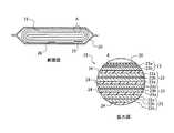
図2は、蓄電池2に搭載される単位電池の一例を示す断面図とその拡大図である。図2に示すように、単位電池は、外装部材20と、外装部材20に収納された扁平上の捲回電極群21と、を有する。捲回電極群21は、正極22と負極23をその間にセパレータ24を介在させて渦巻状に捲回された構造を有する。非水電解質(図示しない)は、捲回電極群21に保持されている。図2に示すように、捲回電極群21の最外周には負極23が位置しており、この負極23の内周側にセパレータ24、正極22、セパレータ24、負極23、セパレータ24、正極22、セパレータ24というように正極22と負極23がセパレータ24を介して交互に積層されている。負極23は、負極集電体23aと、負極集電体23aに担持された負極活物質含有層23bとを備えるものである。負極23の最外周に位置する部分では、負極集電体23aの片面のみに負極活物質含有層23bが形成されている。正極22は、正極集電体22aと、正極集電体22aに担持された正極活物質含有層22bとを備えるものである。図2に示すように、帯状の正極端子25は、捲回電極群21の外周端近傍の正極集電体22aに電気的に接続されている。一方、帯状の負極端子26は、捲回電極群21の外周端近傍の負極集電体23aに電気的に接続されている。正極端子25及び負極端子26の先端は、外装部材20の同じ辺から外部に引き出されている。 FIG. 2 is a cross-sectional view showing an example of a unit battery mounted on the
単位電池に用いられる外装部材20には、金属製容器やラミネートフィルム製容器が用いられる。金属製容器としては、アルミニウム、アルミニウム合金、鉄、ステンレス等からなる金属缶で角形、円筒形のものが使用される。 As the
また、単位電池に用いられる正極22は、正極集電体22aと、正極活物質含有層22bとを含む。正極活物質含有層22bは、正極集電体22aの片面もしくは両面に形成され、活物質、導電剤および結着剤を含む。正極活物質としては、例えば、酸化物及び複合酸化物が用いられる。酸化物には、下記の(i)あるいは(ii)式のいずれかで表される酸化物が含まれる。
LiNixM1yO2 (i)
LiMnuM2vO4 (ii)The
LiNix M1y O2 (i)
LiMnu M2v O4 (ii)
M1は、Mn、Co、Al、Ti、Zr、Cr、V、及びNbよりなる群から選択される少なくとも一種の元素である。x+y=1は、それぞれ、0<x≦1.0、0≦y≦1.0である。M2は、Al、Mg、Ti、Zr、Cr、V、及びNbよりなる群から選択される少なくとも一種の元素である。u+v=2は、それぞれ、0<u≦2.0、0≦v<2.0、である。導電剤は、集電性能を高め、且つ、活物質と集電体との接触抵抗を抑える作用を有する。導電剤としては、例えばアセチレンブラック、カーボンブラック、黒鉛、炭素繊維等が好ましい。結着剤は、活物質、導電剤及び集電体を結着させる作用を有する。結着剤としては、例えばポリテトラフルオロエチレン(PTFE)、ポリフッ化ビニリデン(PVdF)、フッ素系ゴム等が好ましい。正極集電体22aは、アルミニウム箔、又は、Mg、Ti、Zn、Mn、Fe、Cu、及びSiから選択される一以上の元素を含むアルミニウム合金箔等が好ましい。 M1 is at least one element selected from the group consisting of Mn, Co, Al, Ti, Zr, Cr, V, and Nb. x + y = 1 is 0 <x ≦ 1.0 and 0 ≦ y ≦ 1.0, respectively. M2 is at least one element selected from the group consisting of Al, Mg, Ti, Zr, Cr, V, and Nb. u + v = 2 is 0 <u ≦ 2.0 and 0 ≦ v <2.0, respectively. The conductive agent has an effect of enhancing the current collecting performance and suppressing the contact resistance between the active material and the current collector. As the conductive agent, for example, acetylene black, carbon black, graphite, carbon fiber and the like are preferable. The binder has an action of binding an active material, a conductive agent and a current collector. As the binder, for example, polytetrafluoroethylene (PTFE), polyvinylidene fluoride (PVdF), fluorine-based rubber and the like are preferable. The positive electrode
単位電池に用いられる負極23は、負極集電体23aと、負極集電体23aの片面もしくは両面に形成され、活物質、導電剤及び結着剤を含む負極活物質含有層23bとを備える。負極活物質としては、例えば、一般式Li4/3+xTi5/3O4(0≦x)で表せるリチウムチタン酸化物や、一般式LixTiO2(0≦x)で表される単斜晶系(ブロンズ構造(B))やアナターゼ構造のチタン酸化物(充電前構造としてTiO2)や、一般式LixNbaTiO7(0≦X、1≦a≦4)で表されるニオブチタン酸化物等が用いられる。また、ラムスデライド構造のLi2+xTi3O7、Li1+xTi2O4、Li1.1+xTi1.8O4、Li1.07+xTi1.86O4、LixTiO2(xは0≦x)などのリチウムチタン酸化物(リチウムチタン含有複合酸化物)も用いることができる。他には、Nb、Mo、W、P、V、Sn、Cu、Ni、及びFeよりなる群から選択される少なくとも1種類の元素を含有するリチウムチタン酸化物、チタン酸化物を用いても良い。LixTiO2又はLi4/3+xTi5/3O4(0≦x≦2)で表せるリチウムチタン酸化物が好ましい。また、負極としては、高容量化した斜方晶型Na含有ニオブチタン複合酸化物粒子Li2Na2−xTi6−xNbxO14(LNT)を含む新たな材料を用いても良い。また、これらの負極活物質に黒鉛が含まれていても良い。負極集電体23aは、アルミニウム箔又はアルミニウム合金箔が良い。導電剤としては、例えば、アセチレンブラック、カーボンブラック、コークス、炭素繊維、黒鉛、金属化合物粉末、金属粉末等が好ましい。結着剤としては、例えば、ポリテトラフルオロエチレン(PTFE)、ポリフッ化ビニリデン(PVdF)、フッ素系ゴム、スチレンブタジェンゴム、コアシェルバインダー等が好ましい。The
単位電池に用いられるセパレータ24としては、気孔率50%以上のポリエチレン(PE)やポリプロピレン(PP)などのオレフィン系多孔質膜やセルロース繊維が好ましい。繊維径は、10μm以下である不織布、フィルム、紙等が挙げられる。 As the
非水電解質としては、電解質を有機溶媒に溶解することにより調製される液状非水電解質、液状電解質と高分子材料を複合化したゲル状非水電解質、又はリチウム塩電解質と高分子材料を複合化した固体非水電解質が挙げられる。また、リチウムイオンを含有した常温溶融塩(イオン性融体)を非水電解質として使用してもよい。高分子材料としては、例えば、ポリフッ化ビニリデン(PVdF)、ポリアクリロニトリル(PAN)、ポリエチレンオキサイド(PEO)等を挙げることができる。 As the non-aqueous electrolyte, a liquid non-aqueous electrolyte prepared by dissolving the electrolyte in an organic solvent, a gel-like non-aqueous electrolyte in which a liquid electrolyte and a polymer material are combined, or a lithium salt electrolyte and a polymer material are combined. Examples include solid non-aqueous electrolytes. Further, a room temperature molten salt (ionic melt) containing lithium ions may be used as the non-aqueous electrolyte. Examples of the polymer material include polyvinylidene fluoride (PVdF), polyacrylonitrile (PAN), polyethylene oxide (PEO) and the like.
電池パックに含まれる複数の単位電池は、電気的に直列、並列、又は直列及び並列を組み合わせて接続されることができる。複数の単位電池は、電気的に接続されて組電池を構成することもできる。電池パックは、複数の組電池を含んでいても良い。なお、蓄電池という用語は、電池パック、電池モジュール(組電池)、単位電池、及び二次電池が含まれるものとする。 The plurality of unit batteries included in the battery pack can be electrically connected in series, in parallel, or in combination of series and parallel. A plurality of unit batteries can also be electrically connected to form an assembled battery. The battery pack may include a plurality of assembled batteries. The term storage battery shall include a battery pack, a battery module (assembled battery), a unit battery, and a secondary battery.
次に、体積測定部3について説明する。 Next, the
体積測定部3は、蓄電池2の単位電池それぞれの体積変化を測定する。体積測定部3は、単位電池の外装部材20の表面に設置される。本実施形態にかかる蓄電池2は、充電時に電流が流されるため、充電状態に応じて各単位電池が膨張及び収縮する。これは、蓄電池2が、充放電を行う際に、イオンの吸蔵及び放出をすることにより活物質の体積が変化するためである。単位電池の体積変化は、活物質に力学的な負荷を与え、活物質の物理的な破壊(例えば、き裂等)を引き起こすため、単位電池の性能を低下させる。また、単位電池の体積変化は、イオンの吸蔵及び放出により生じるため、電流が大きい場合に体積変化率が大きくなる。一方、電流が小さい場合には体積変化率は小さくなる。体積測定部3は、各単位電池の膨張及び収縮時の体積変化を測定する。測定される体積変化は、単位時間当たりの体積変化率又は体積変化量(差分)で良い。また、体積変化とは、単位電池の厚みの変化等も含む。体積測定部3により測定される単位電池は、複数であることに限定されず1つであっても良い。体積測定部3は、例えば、単位電池の厚みを測定する変位計、歪ゲージ、又は圧力センサ等が用いられる。単位電池のある一方向の変位を測定してそれを体積変化に換算しても良い。単位電池の形状が角型形状である場合、体積測定部3による測定は、最も表面積の大きい箇所で行うのが良い。体積測定部3により測定された体積変化は、充電制御部4に出力される。体積測定部3により測定された体積変化のデータは、充電制御部4に常時出力しなくても良く、所定の時間間隔で出力しても良い。 The
次に、充電制御部4について説明する。 Next, the
充電制御部4は、体積測定部3の測定結果と後述する指定部5で指定された閾値に基づいて、蓄電池2に流す電流を制御する。充電制御部4は、第2測定部40と、導出部41と、を備える。 The
第2測定部40は、蓄電池2の電流、電圧、温度等の情報を測定し導出部41に出力する。第2測定部40は、電流、電圧、温度を測定可能なセンサ等で良い。 The
導出部41は、体積測定部3で測定された蓄電池2の体積変化率と、第2測定部40で測定された電流、電圧、温度等の情報と、後述する指定部5で指定された閾値と、に基づいて蓄電池2の体積変化率が閾値を超えないように蓄電池2に流す電流を制御する。詳しく述べると、充電制御部4が蓄電池2に所定の電流を流している時に、蓄電池2の体積変化が閾値以上となる場合、蓄電池2に流す電流を所定の電流より小さく制御し、蓄電池2の体積変化が閾値以下の場合、蓄電池2に流す電流を所定の電流より大きく制御する。所定の電流とは、蓄電池を充電する際に流す電流のことを示す。所定の電流は、経験則や蓄電池の特性に応じて任意に設定される。例えば、CC−CV(constant current - constant voltage:定電流定電圧)充電の際の定電流等が該当する。充電制御部4は、蓄電池2の充電状態の初期に所定の電流を流し、蓄電池2の体積変化が閾値を超えない場合、電流を所定の電流より大きく制御し、蓄電池2の体積変化が閾値を超える場合、電流を所定の電流より小さく制御する。また、充電制御部4は、蓄電池2に流す電流値に基づいて充電量を導出して所定の充電量を満たしたか否かを判定する機能を有する。所定の充電量を満たしたか否かの判定は、予め設定された条件に基づいて行えば良い。導出部41は、例えばCPU(中央演算処理装置:Central Processing Unit)やメモリや補助記憶部などを備え、プログラム等を実行する。なお、全て又は一部は、ASIC(Application Specific Integrated Circuit)やPLD(Programmable Logic Device)やFPGA(Field Programmable Gate Array)等のハードウェアを用いて実現されても良い。 The lead-out
充電制御部4は、蓄電池2に所定の電流を流す時間を任意に設定しても良い。所定の電流を蓄電池2に長時間流しても、蓄電池2の体積変化が閾値より小さい場合もあるため、所定の電流を一定時間流した後に電流を大きくするよう制御すれば良い。また、第2測定部40は、充電制御部4に含まれる場合について説明したが、それに限定されず充電制御部4と別構成であっても良い。 The
次に、指定部5について説明する。 Next, the
指定部5は、蓄電池2の体積変化についての閾値を指定する。充電制御部4が蓄電池2の単位時間当たりの体積変化率に基づいて制御する場合、指定部5には体積変化率に関する閾値が入力される。指定部5に入力される閾値は、過去のデータや蓄電池2の特性に応じて作業者(ユーザ)により任意に設定される。例えば、蓄電池2の劣化が顕著となる体積変化率以下に閾値を設定するのが良い。 The
指定部5での閾値の指定は、PC(パーソナルコンピュータ)や携帯等の外部端末を用いて行っても良いし、モニタやタッチパネル等を取り付けて直接入力しても良い。外部端末により指定する場合は、インターネット、Wi−FiやBluetooth(登録商標)等を用いてデータの転送を行っても良い。 The threshold value may be designated by the
指定部5で指定された閾値は、充電制御部4に出力される。蓄電池2の特性によって閾値が明らかに決まる場合は、指定部5で閾値を入力する必要は無く、充電制御部4が閾値に関する情報を有していれば良い。その場合、指定部5は、必須の構成ではない。あるいは、充電制御部4が指定部5を含んでいても良い。また、指定部5に入力する閾値は、固定値であることに限定されず、例えば充電時間に応じた変動値であっても良い。 The threshold value designated by the designated
次に、本実施形態にかかる二次電池システムの動作の一例について説明する。 Next, an example of the operation of the secondary battery system according to the present embodiment will be described.
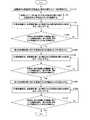
図3は、第1の実施形態にかかる二次電池システムの動作の一例を示すフロー図である。 FIG. 3 is a flow chart showing an example of the operation of the secondary battery system according to the first embodiment.
まず、指定部5に蓄電池2の単位時間当たりの体積変化率に関する情報を指定する(ステップ301)。充電制御部4が蓄電池2の体積変化率に関する情報を予め有している場合、このステップは省略される。 First, information regarding the volume change rate per unit time of the
充電制御部4は、蓄電池2に所定の電流を流す(ステップ302)。 The
体積測定部3は、蓄電池2の体積変化を測定し、充電制御部4に出力する(ステップ303)。 The
充電制御部4は、指定部5に入力された閾値と蓄電池2の体積変化率を比較する(ステップ304)。 The
蓄電池2の体積変化率が閾値以上の場合(ステップ304、Yes)、充電制御部4は、体積変化率が閾値より小さくなるように蓄電池2に流れる電流を所定の電流より小さく制御する(ステップ305)。 When the volume change rate of the
蓄電池2の体積変化率が閾値より小さい場合(ステップ304、No)、充電制御部4は、体積変化率が閾値に近づくように蓄電池2に流れる電流を所定の電流より大きく制御する(ステップ306)。 When the volume change rate of the
充電制御部4は、蓄電池2が満充電状態(100%充電)であるか否かを判定する(ステップ307)。 The
充電制御部4は、蓄電池2が満充電ではないと判定した場合(ステップ307、No)、ステップ303に戻る。 When the
充電制御部4は、蓄電池2が満充電と判定した場合(ステップ307、Yes)、蓄電池2への電流供給を停止する(ステップ308)。その後、処理を終了する。 When the
本実施形態にかかる二次電池システム1を用いることにより充電時に蓄電池2の体積変化に応じた電流制御ができるため、蓄電池2の劣化を低減した充電ができる。 By using the
また、体積測定部3により蓄電池2の体積変化をタイムリーに測定できるため、効率的な電流制御が可能となり、充電時間の短縮を図ることができる。 Further, since the
また、蓄電池2に同一の単位電池を複数用いることにより、一つの単位電池の体積変化を測定することで他の単位電池の体積変化を推測でき、簡易な構成で二次電池システムを実現できる。 Further, by using a plurality of the same unit batteries for the
(第2の実施形態)
第2の実施形態について図4を参照して説明する。図4は、第2の実施形態にかかる二次電池システムの一例を示すブロック図である。(Second Embodiment)
The second embodiment will be described with reference to FIG. FIG. 4 is a block diagram showing an example of the secondary battery system according to the second embodiment.
図4に示すように二次電池システム1は、蓄電池2と、充電制御部4と、指定部5と、推定部6と、記憶部7と、を備える。第2の実施形態にかかる二次電池システムは、体積測定部3に代わり推定部6と記憶部7を備える。それ以外の構成については、第1の実施形態にかかる二次電池システムと同様である。 As shown in FIG. 4, the
第2の実施形態にかかる二次電池システムは、第2測定部40で測定されたデータと、記憶部7に予め記憶されたデータに基づいて、推定部6によって蓄電池2の体積変化を推定する。そして、充電制御部4は、推定部6で推定された蓄電池2の体積変化と指定部5で指定された閾値に基づいて蓄電池2に流す電流を制御する。 In the secondary battery system according to the second embodiment, the volume change of the
まず、推定部6について詳しく説明する。 First, the estimation unit 6 will be described in detail.
推定部6は、CPU61と、RAM(RWM)62と、通信IF63と、ROM64と、記憶部65を含む。その他、USBメモリ等の外部記憶装置を装着するIF(インターフェース)を備えていても良い。推定部6は、プログラムを実行し演算するコンピュータである。 The estimation unit 6 includes a
推定部6は、通信IF63を介して第2測定部40により測定された蓄電池2の電流及び電圧等のデータを収集し、収集したデータを用いて各種導出処理を行う。 The estimation unit 6 collects data such as the current and voltage of the
CPU61は、ROM64に予め書き込んだ各プログラムをRAM62に読み出し、導出処理を行う演算処理部(マイクロプロセッサ)である。CPU61は、機能に合わせて複数のCPU群(マイクロコンピュータ、マイクロコントローラ)で構成することができる。またCPU内にRAM機能を有した内蔵メモリを備えていてもよい。 The
RAM(RWM)62は、CPU61がプログラムを実行する際に使用する記憶エリアであって、ワーキングエリアとして用いられるメモリである。処理に必要なデータを一次記憶させるのに好ましい。 The RAM (RWM) 62 is a storage area used by the
通信IF63は、充電制御部4とデータの授受を行う通信装置、通信手段である。例えば、ルーター等である。本実施形態では通信IF63と蓄電池2との接続は有線通信のように記載しているが、各種無線通信網に代替することができる。また、通信IF63と充電制御部4との接続は一方向又は双方向通信可能なネットワークを介して行われる形態であっても良い。 The communication IF 63 is a communication device and a communication means for exchanging data with the
ROM64は、推定プログラム641を格納するプログラムメモリである。データの書き込みはできない非一次記憶媒体を用いることが好ましいが、データの読み出し、書き込みが随時できる半導体メモリ等の記憶媒体であっても良い。また、取得したデータを記憶部65に予め定められた時間毎に記憶させる情報登録プログラムなどが格納されていても良い。 The
推定プログラム641は、蓄電池2を構成する単位電池毎又は組電池毎の正極、負極の容量値、内部抵抗値を導出する機能をCPU61に実現させる手段である。例えば、数式(1)に示す7つの値、(a)正極を構成する活物質Aの容量、(b)正極を構成する活物質Bの容量、(c)負極の容量、(d)正極を構成する活物質Aの充電量、(e)正極を構成する活物質Bの充電量、(f)負極の充電量、(g)内部抵抗値、を導出(解析)する。
これらの値を用いて、時間に対する充電電圧の変化特性、充電量に対する正極の電位又は充電量に対する負極の電位特性を導出する。具体的動作については後述する。 Using these values, the change characteristic of the charging voltage with respect to time, the potential of the positive electrode with respect to the charge amount, or the potential characteristic of the negative electrode with respect to the charge amount is derived. The specific operation will be described later.
推定プログラム641は以下の各数式に対応するプログラム群により構成されている。なお、各プログラムの順番については、各種変更が可能である。 The estimation program 641 is composed of a group of programs corresponding to each of the following mathematical expressions. The order of each program can be changed in various ways.
充電電圧VCは、電池の起電圧Ve、内部抵抗による電圧VRを用いて次の数式(2)から求められる。
電池の起電圧Veは、正極の電位Ec、負極の電位Eaを用いて次の数式(3)から求められる。
正極と負極の電位は、充電量(q)、初期状態での正極の容量Qic、初期状態での負極の容量Qiaを用いて数式(4)、数式(5)から求められる。
ここで、複数の活物質で正極又は負極を構成する場合について説明する。 Here, a case where a positive electrode or a negative electrode is composed of a plurality of active materials will be described.
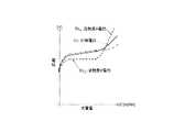
図5は、それぞれの活物質の起電力が異なる場合の特性を示す図である。 FIG. 5 is a diagram showing characteristics when the electromotive force of each active material is different.
活物質A(例えば、マンガン酸リチウム)と活物質B(例えば、コバルト酸リチウム)を混合した複合正極の起電圧の充電量に対する特性を導出する。 The characteristics of the electromotive voltage of the composite positive electrode obtained by mixing the active material A (for example, lithium manganate) and the active material B (for example, lithium cobalt oxide) with respect to the charge amount are derived.
図6は、活物質Aと活物質Bを混合した複合正極の起電圧と充電量に対する特性を導出した図である。 FIG. 6 is a diagram in which the characteristics with respect to the electromotive voltage and the charge amount of the composite positive electrode in which the active material A and the active material B are mixed are derived.
活物質Aの正極の電位EcA及び活物質Bの正極の電位EcBは、初期状態の活物質Aの容量QicAと、初期状態の活物質Bの容量QicB、活物質Aの充電量qA、活物質Bの充電量qBとを用いて数式(6)〜(9)として求められる。
よって、混合正極の電位Ecは、活物質Aの正極の充電開始時の容量qA、活物質Aの正極の充電量QcA又は活物質Bの正極の充電開始時の容量qB、活物質Bの正極の充電量QcBを用いて数式(10)として求められる。
なお、活物質Aの正極の電位EcAと活物質Bの正極の電位EcBは、各活物質表面の電位である。したがって、活物質内でのリチウムイオンの拡散抵抗により活物質内でのリチウムイオンの分布が変わるので充電電流により充電量と起電圧の関係が変わってしまうようにも思われる。しかしながら、本実施形態では、正極に使われる活物質や負極に使われる炭素系の活物質では、活物質内の拡散抵抗が小さいため、充電電流が変化しても、充電電流と起電圧の関係が大きくは変わらないものとしている。The potential E cA of the positive electrode of the active material Aand the potential E cB of the positive electrode of the active material B are the potentials on the surface of each active material. Therefore, since the distribution of lithium ions in the active material changes due to the diffusion resistance of lithium ions in the active material, it seems that the relationship between the charge amount and the electromotive voltage changes depending on the charging current. However, in the present embodiment, since the active material used for the positive electrode and the carbon-based active material used for the negative electrode have a small diffusion resistance in the active material, the relationship between the charging current and the electromotive voltage even if the charging current changes. Is not significantly different.
一方、負極に活物質としてチタン酸リチウムのような拡散抵抗の大きな材料を用いた場合は、図5に示すように電流値によって充電量と起電圧の関係が大きく変化するため正極と同様の近似は行わない。 On the other hand, when a material having a large diffusion resistance such as lithium titanate is used as the active material for the negative electrode, the relationship between the charge amount and the electromotive voltage changes greatly depending on the current value as shown in FIG. Do not do.
よって、負極電位Eaは、数式(11)として求められる。
また、内部抵抗による電圧VRは、充電電流Iと内部抵抗R(q)を用いて数式(12)、(13)で求められる。
つまり、数式(2)は、以下の数式(14)のように求められる。
上述したように、充電電圧と、蓄電池2の活物質の起電圧特性及び内部抵抗には非線形の相関関係がある。活物質の容量、内部抵抗を変数として充電電圧の充電量に対する特性カーブについて回帰計算を行い、活物質の容量、内部抵抗、各活物質の充電開始時の容量等を導出する。 As described above, there is a non-linear correlation between the charging voltage and the electromotive voltage characteristics and internal resistance of the active material of the
推定部6は、推定した蓄電池2の充電量もしくは蓄電池2に使用されている活物質の充電量と、後述する記憶部に記憶された蓄電池2の充電量もしくは蓄電池2に使用されている活物質の充電量と、体積変化率を示すデータに基づいて蓄電池2の体積変化率を推定する。 The estimation unit 6 includes an estimated charge amount of the
記憶部7には、蓄電池2の充電量と体積変化率の関係もしくは蓄電池2に使用されている活物質の充電量と体積変化率の関係を示すデータが予め記憶される。例えば、充電量と体積変化率を紐づけたテーブルデータとして記憶しても良い。また、記憶するデータは体積変化率に限定されず蓄電池2の厚みデータと充電量との関係や、蓄電池2の体積変化量と充電量との関係を示すデータであっても良い。推定部6は、記憶部7に記憶されたデータを用いて蓄電池2の体積変化率を推定する。記憶部7として、例えば、磁気テープやカセットテープ等のテープ系、フロッピー(登録商標)ディスク/ハードディスク等の磁気ディスクやCD−ROM/MO/MD/DVD/CD−R等の光ディスクを含むディスク系、ICカード(メモリカードを含む)/光カード等のカード系、あるいはマスクROM/EPROM/EEPROM/フラッシュROM等の半導体メモリ系などを用いることができる。 The storage unit 7 stores in advance data showing the relationship between the charge amount of the
次に、本実施形態にかかる二次電池システムの動作の一例について説明する。 Next, an example of the operation of the secondary battery system according to the present embodiment will be described.
図7は、第2の実施形態にかかる二次電池システムの動作の一例を示すフロー図である。 FIG. 7 is a flow chart showing an example of the operation of the secondary battery system according to the second embodiment.
まず、指定部5に蓄電池2の単位時間当たりの体積変化率に関する情報を指定する(ステップ701)。上述したが、充電制御部4が蓄電池2の体積変化率に関する情報を予め有している場合、このステップは省略される。 First, information regarding the volume change rate per unit time of the
充電制御部4は、蓄電池2に所定の電流を流す(ステップ702)。 The
充電制御部4の第2測定部40は、蓄電池2の電流、充電電圧、及び温度データ等を測定し、推定部6に出力する(ステップ703)。この時、第2測定部40は、充電電圧等の時間変化を単位電池毎に測定することが好ましい。測定した各単位電池の充電電圧等のデータをRAM62又は記憶部7に記憶する。充電開始から充電終止電圧に到達するまでの充電時間tcの間に例えばN個の測定値が得られる。The
推定部6のCPU61は、ROM64から推定プログラム641を実行し、非線形微分方程式の解を回帰計算により解析する(ステップ704)。 The
定電流充電を行っているので充電開始からの充電量qcは、数式(13)からqc=I・tを求める。このように充電量qcに対応した測定値(V1,qc1)、(V2,qc2)、………、(VN,qcN)を得る。CPU61は、得られた値をRAM62に一時格納又は記憶部7に記憶させる。Since constant current charging is performed, the charge amount qc from the start of charging is obtained from the mathematical formula (13) as qc = I · t. Measurements corresponding to such charge amountq c (V 1, q c1 ), (
上記測定値を用いて回帰計算を行う。回帰計算を行う際に使用する残差平方和は、下記数式(15)で表される。
充電開始時の充電量は回帰計算時には未知数であることから、上記充電開始時の正極及び負極の充電量も未知数となる。本実施形態では、正極が活物質Aと活物質Bの複合正極の場合には、回帰計算の未知数は、以下数式(16)となる。
初期値としては、適当な値、例えば、前回測定時の値を用いる(ステップ705)。 As the initial value, an appropriate value, for example, the value at the time of the previous measurement is used (step 705).
次の数式(17)の連立方程式を生成する(ステップ706)。
次のステップの各値は次の数式(18)で求められる(ステップ707)。
このとき、数式(19)は、
次の数式(20)を解いて得られる。本実施形態では、ニュートン法を用いて説明しているが、これに代えてレーベンバーグ、マルカート法などの他の数値解析法を用いても良い。
求めた値が以下の数式(21)の収束条件(収束半径)を満たすか否かを判定する(ステップ708)。
収束条件を満たさない場合は(ステップ708、No)、初期値を再設定する(ステップ705)。 If the convergence condition is not satisfied (step 708, No), the initial value is reset (step 705).
収束条件を満たす場合は(ステップ708、Yes)、蓄電池2の充電電圧、充電量等の推定データと、記憶部7に記憶された充電量と体積膨張率のデータに基づいて推定部が蓄電池の体積膨張率の推定結果を充電制御部4に出力する(ステップ709)。例えば、推定部6は、前回の充電時に測定された蓄電池の電流、充電電圧、及び温度データ等に基づいて、ステップ704からステップ708の処理を実行し、導出された活物質の容量、内部抵抗、各活物質の充電開始時の容量等を記憶部等に保存する。そして、保存した活物質の容量、内部抵抗、各活物資の充電開始時の容量等に基づいてステップ709を実行する場合、ステップ704からステップ708の処理は、省略される。 When the convergence condition is satisfied (step 708, Yes), the estimation unit of the storage battery is based on the estimation data such as the charge voltage and the charge amount of the
充電制御部4は、指定部5に入力された閾値と推定された蓄電池2の体積変化率を比較する(ステップ710)。 The
蓄電池2の体積変化率が閾値以上の場合(ステップ710、Yes)、充電制御部4は、体積変化率が閾値より小さくなるように蓄電池2に流れる電流を所定の電流より小さく制御する(ステップ711)。 When the volume change rate of the
蓄電池2の体積変化率が閾値より小さい場合(ステップ710、No)、充電制御部4は、体積変化率が閾値に近づくように蓄電池2に流れる電流を所定の電流より大きく制御する(ステップ712)。 When the volume change rate of the
充電制御部4は、蓄電池2が満充電状態(100%充電)であるか否かを判定する(ステップ713)。 The
充電制御部4は、蓄電池2が満充電ではないと判定した場合(ステップ713、No)、ステップ703に戻る。 When the
充電制御部4は、蓄電池2が満充電と判定した場合(ステップ713、Yes)、蓄電池2への電流供給を停止する(ステップ714)。その後、処理を終了する。 When the
蓄電池2が満充電であるか否かの判定は、推定部6の充電量の推定値等から充電制御部4が随時行えば良い。または、所定の時間毎に充電制御部4が充電量をモニタリングすることにより行えば良い。 The
本実施形態にかかる二次電池システムは、推定部6と記憶部7を別の構成としたが、記憶部7は、推定部6に含まれても良い。また、推定部6と記憶部7は、充電制御部4に含まれても良い。 In the secondary battery system according to the present embodiment, the estimation unit 6 and the storage unit 7 have different configurations, but the storage unit 7 may be included in the estimation unit 6. Further, the estimation unit 6 and the storage unit 7 may be included in the
本実施形態にかかる二次電池システムを用いることにより、体積測定部3を有さなくても第1の実施形態にかかる二次電池システムと同一の作用効果を得ることができる。 By using the secondary battery system according to the present embodiment, the same operation and effect as the secondary battery system according to the first embodiment can be obtained without having the
また、二次電池システムは、体積測定部3を有さないため省スペースであり、かつ簡易な構成とすることができる。 Further, since the secondary battery system does not have the
(第3の実施形態)
第3の実施形態について図8を参照して説明する。図8は、第3の実施形態にかかる二次電池システムの一例を示すブロック図である。(Third Embodiment)
The third embodiment will be described with reference to FIG. FIG. 8 is a block diagram showing an example of the secondary battery system according to the third embodiment.
第3の実施形態にかかる二次電池システム1は、蓄電池(単位電池)の充電量と蓄電池の厚みとの関係を示すデータが記憶された記憶部70を備える。それ以外の構成については、第1の実施形態にかかる二次電池システムと同様である。 The
記憶部70には、所定の電流が流された場合の単位電池の充電量と厚みの関係を表すデータが格納されている。格納されているデータは、蓄電池2の厚みに限定されず体積変化率等であっても良い。また、単位電池の種類毎に上記データが格納されている。記憶部70として、例えば、磁気テープやカセットテープ等のテープ系、フロッピー(登録商標)ディスク/ハードディスク等の磁気ディスクやCD−ROM/MO/MD/DVD/CD−R等の光ディスクを含むディスク系、ICカード(メモリカードを含む)/光カード等のカード系、あるいはマスクROM/EPROM/EEPROM/フラッシュROM等の半導体メモリ系などを用いることができる。 The
図9は、単位電池の負極に黒鉛が使用されている場合の充電量と単位電池の厚みとの関係を示す図である。横軸が単位電池の充電量を示し、値を0〜100%で示している。縦軸は、単位電池の厚みを示している。 FIG. 9 is a diagram showing the relationship between the charge amount and the thickness of the unit battery when graphite is used for the negative electrode of the unit battery. The horizontal axis indicates the charge amount of the unit battery, and the value is indicated by 0 to 100%. The vertical axis shows the thickness of the unit battery.
図9に示すように、単位電池の負極に黒鉛が使用されている場合、単位電池の厚み変化は、低充電量区間(充電初期又は第1の区間とも称する)と中充電量区間(充電中期又は第2の区間とも称する)と高充電量区間(充電末期又は第3の区間とも称する)の3つに分類され、第1の区間と第3の区間では単位電池の厚みの変化率が大きく、第2の区間では、単位電池の厚みの変化率が小さい。厚みの変化率が小さいとは、体積変化率が小さいことを意味する。また、厚みの変化率が大きいとは、体積変化率が大きいことを意味する。第1〜第3の区間は、連続した区間である。 As shown in FIG. 9, when graphite is used for the negative electrode of the unit battery, the thickness change of the unit battery is the low charge amount section (also referred to as the initial charge or the first section) and the medium charge amount section (mid-charge charge period). It is also classified into three sections, a high charge amount section (also referred to as the end of charging or the third section), and the rate of change in the thickness of the unit battery is large in the first section and the third section. In the second section, the rate of change in the thickness of the unit battery is small. A small rate of change in thickness means a small rate of change in volume. Further, a large rate of change in thickness means a large rate of change in volume. The first to third sections are continuous sections.
黒鉛材料の体積変化は、リチウムイオンの吸蔵量に応じて黒鉛の持つ結晶構造(ステージ)が段階的に変化することにより生じる。各ステージで体積変化率が異なり、ステージが移行することにより体積変化率が変化する。したがって、体積変化率の大きい第1の区間と第3の区間において、単位時間当たりの充電量(電流値)を小さくし、第2の区間において単位時間当たりの充電量(電流値)を大きくすれば、充電時間を延ばすことなく単位電池の劣化を低減できる。また、単位電池の劣化を低減しつつ充電時間を短縮できる。第1〜第3の区間で流す電流は、複数の定電流値で設定されても良い。 The volume change of the graphite material is caused by the stepwise change of the crystal structure (stage) of graphite according to the occluded amount of lithium ions. The volume change rate is different in each stage, and the volume change rate changes as the stages shift. Therefore, in the first section and the third section where the volume change rate is large, the charge amount (current value) per unit time should be reduced, and the charge amount (current value) per unit time should be increased in the second section. For example, deterioration of the unit battery can be reduced without extending the charging time. In addition, the charging time can be shortened while reducing the deterioration of the unit battery. The current flowing in the first to third sections may be set by a plurality of constant current values.
また、単位電池は、充電すると温度が上昇し、更に温度が上昇すると電池の劣化の進行が早まるため、第1の区間よりも第3の区間で流す平均電流値を小さくすることが好ましい。この時の平均電流値とは、充電量に対して計算され、CV区間(定電圧区間)は含まないものとする。第1の区間の平均電流値I1と第3の区間の平均電流値I3の比は、1.0<I1/I3<1.6を満たすのが良く、更に好ましくは、1.25<I1/I3<1.45を満たすのが良い。Further, when the unit battery is charged, the temperature rises, and when the temperature rises further, the deterioration of the battery accelerates. Therefore, it is preferable to make the average current value flowing in the third section smaller than that in the first section. The average current value at this time is calculated with respect to the amount of charge, and does not include the CV section (constant voltage section). The ratio of the average current valueI 3 in the average current valueI 1 and the third section of the first sectionhas good meet 1.0<I 1 / I 3 <1.6, more preferably 1. It is better to satisfy 25 <I1 / I3 <1.45.
次に、本実施形態にかかる二次電池システムの動作の一例について説明する。 Next, an example of the operation of the secondary battery system according to the present embodiment will be described.
図10は、第3の実施形態にかかる二次電池システムの動作の一例を示すフロー図である。 FIG. 10 is a flow chart showing an example of the operation of the secondary battery system according to the third embodiment.
まず、充電制御部4は、記憶部70から蓄電池2の充電量と厚みに関するデータを取得する(ステップ1001)。 First, the
充電制御部4は、取得したデータに基づいて第1の区間の間に流す定電流を所定の電流より小さく制御する(ステップ1002)。 The
充電制御部4は、体積測定部3により測定される蓄電池2の厚みの変化をモニタリングする(ステップ1003)。 The
次に、充電制御部4は、蓄電池に流す電流値と充電時間に基づいて充電量を導出し、第1の区間に対応する充電量になったか否かを判定する(ステップ1004)。 Next, the
第1の区間に対応する充電量になっている場合(ステップ1004、Yes)、第2の区間の間に流す定電流を所定の電流より大きく設定する(ステップ1005)。 When the charge amount corresponds to the first section (step 1004, Yes), the constant current flowing between the second sections is set to be larger than the predetermined current (step 1005).
第1の区間に対応する充電量になっていない場合(ステップ1004、No)、ステップ1003に戻る。 If the charge amount does not correspond to the first section (step 1004, No), the process returns to step 1003.
充電制御部4は、体積測定部3により測定される蓄電池2の厚みの変化をモニタリングする(ステップ1006)。 The
次に、充電制御部4は、蓄電池に流す電流値と充電時間に基づいて充電量を導出し、第2の区間に対応する充電量になったか否かを判定する(ステップ1007)。 Next, the
第2の区間に対応する充電量になっている場合(ステップ1007、Yes)、第3の区間の間に流す定電流を所定の電流より小さく設定する(ステップ1008)。この時、更に第1の区間で流した電流値より小さくなっていることが好ましい。 When the charge amount corresponds to the second section (step 1007, Yes), the constant current flowing between the third sections is set to be smaller than the predetermined current (step 1008). At this time, it is preferable that the value is smaller than the current value passed in the first section.
第2の区間に対応する充電量になっていない場合(ステップ1007、No)、ステップ1006に戻る。 If the charge amount does not correspond to the second section (step 1007, No), the process returns to step 1006.
充電制御部4は、体積測定部3により測定される蓄電池2の厚みの変化をモニタリングする(ステップ1009)。 The
次に、充電制御部4は、蓄電池に流す電流値と充電時間に基づいて充電量を導出し、第3の区間に対応する充電量になったか否かを判定する(ステップ1010)。 Next, the
第3の区間に対応する充電量になっている場合(ステップ1010、Yes)、処理を終了する。 When the charge amount corresponds to the third section (
第3の区間に対応する充電量になっていない場合(ステップ1010、No)、ステップ1009に戻る。 If the charge amount does not correspond to the third section (
第1〜第3の区間で流す電流の大きさは、充電時間により適宜変更することができる。また、第1〜第3の区間で流す電流は、定電流であることに限定されず、体積測定部3による蓄電値の測定結果により適宜変更することができる。 The magnitude of the current flowing in the first to third sections can be appropriately changed depending on the charging time. Further, the current flowing in the first to third sections is not limited to a constant current, and can be appropriately changed depending on the measurement result of the stored electricity value by the
図11は、黒鉛を蓄電池の負極に用いた場合に、(I1/I3)の比を変化させてサイクル試験を行った際の結果を示す図である。横軸が、第1の区間と第3の区間の平均電流の比(I1/I3)を示し、縦軸が、蓄電池の容量維持率が80%となったときのサイクル数を示す。(I1/I3)が1である場合は、従来のCC−CV充電を示す。CC−CV充電の充電時間を基準として、充電時間が同等になるように各条件の電流を設定した。図11に示すように、(I1/I3)が1.4の場合が最もサイクル数が大きい結果であった。FIG. 11 is a diagram showing the results when a cycle test was performed by changing the ratio of(I 1 / I3 ) when graphite was used as the negative electrode of the storage battery. The horizontal axis shows the ratio of the average current between the first section and the third section (I1 / I3 ), and the vertical axis shows the number of cycles when the capacity retention rate of the storage battery reaches 80%. When (I1 / I3 ) is 1, it indicates conventional CC-CV charging. Based on the charging time of CC-CV charging, the current of each condition was set so that the charging time would be the same. As shown in FIG. 11,the case where (I 1 / I3 ) was 1.4 was the result with the largest number of cycles.
図12は、0.7C−CCCV充電と0.8C−0.9C−0.6CCV充電の場合のサイクル数と容量維持率の関係を示す図である。 FIG. 12 is a diagram showing the relationship between the number of cycles and the capacity retention rate in the case of 0.7C-CCCV charging and 0.8C-0.9C-0.6CCV charging.
図12に示すように、0.8C−0.9C−0.6CCV充電の場合の方がサイクル数に対して容量維持率が高いことが解る。つまり、充電を行う際に少なくとも3つの区間を含む充電状態を有し、各充電状態の平均電流値が(第3の区間<第1の区間<第2の区間)とすることにより、充電時間を延ばすことなく蓄電池の劣化を低減することができる。 As shown in FIG. 12, it can be seen that the capacity retention rate is higher with respect to the number of cycles in the case of 0.8C-0.9C-0.6CCV charging. That is, when charging, the charging time includes at least three sections, and the average current value of each charging state is (third section <first section <second section). It is possible to reduce the deterioration of the storage battery without extending the battery.
上記説明では、第1測定部を有する場合について説明したが、本実施形態において第1測定部は省略可能である。第1測定部の省略に伴い、図10に示す、ステップ1003、ステップ1006、ステップ1008の処理も省略可能である。 In the above description, the case where the first measuring unit is provided has been described, but the first measuring unit can be omitted in the present embodiment. With the omission of the first measuring unit, the processes of step 1003, step 1006, and step 1008 shown in FIG. 10 can also be omitted.
また、第1の区間の充電量を0〜qxとし、第2の区間の充電量をqx〜qyとし、第3の区間の充電量をqy〜qzとし、蓄電池の充電量をqcnとし、負極(黒鉛)の容量をQaとして、蓄電池の充電量を導出すると、第1の区間は、数式(22)で表される。
数式(22)から、第1の区間での蓄電池の充電量は、0〜(Qa×qx−q0a)となる。同様に、第2の区間の蓄電池の充電量は、(Qa×qx−q0a)〜(Qa×qy−q0a)となる。第3の区間は、(Qa×qy−q0a)〜(Qa×qz―q0a)となる。負極の初期充電量q0aや容量Qaは、予め記憶部に保存された値を用いても良いが、第2の実施形態にかかる推定部を用いた充電曲線解析法やdVdQ法等の電池内部状態推定手法によって、適宜更新するのが好ましい。From the mathematical formula (22), the charge amount of the storage battery in the first section is 0 to (Qa × qx −q0a ). Similarly, the charge amount of the storage battery in the second section is (Qa × qx −q0a ) to (Qa × qy −q0a ). The third section is (Qa × qy −q0a ) to (Qa × qz −q0a ). For the initial charge amount q0a and the capacity Qa of the negative electrode, values stored in advance in the storage unit may be used, but a charge curve analysis method or a dVdQ method using the estimation unit according to the second embodiment may be used. It is preferable to update as appropriate by the battery internal state estimation method.
(第4の実施形態)
第4の実施形態について図13を参照して説明する。図13は、第4の実施形態にかかる車両の一例を示す図である。(Fourth Embodiment)
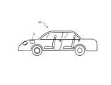
A fourth embodiment will be described with reference to FIG. FIG. 13 is a diagram showing an example of the vehicle according to the fourth embodiment.
本実施形態の車両は、第1乃至3の実施形態にかかる二次電池システムを具備する。ここでいう車両としては、二輪〜四輪のアイドリングストップ機構を搭載した自動車、二輪〜四輪のハイブリッド電気自動車、二輪〜四輪の電気自動車、アシスト自転車、電車等が挙げられる。 The vehicle of the present embodiment includes the secondary battery system according to the first to third embodiments. Examples of the vehicle referred to here include a vehicle equipped with a two-wheel to four-wheel idling stop mechanism, a two-wheel to four-wheel hybrid electric vehicle, a two-wheel to four-wheel electric vehicle, an assisted bicycle, and a train.
図13に示すように、第4の実施形態の車両10は、エンジンルームに第1乃至3の実施形態にかかる二次電池システム1が搭載されている。高温環境下となる車両のエンジンルームに二次電池システム1を設置することにより、電池パックからモータ、インバータ等の電動駆動系装置までの距離が短くなり、出入力のロスが低減し、燃費効率が向上する。 As shown in FIG. 13, the
第1乃至3にかかる二次電池システムを具備するので、優れたサイクル特性や充電性能を示すことができる二次電池システム1を搭載した車両10を提供することができる。 Since the secondary battery system according to the first to third is provided, it is possible to provide the
また、第1乃至3にかかる二次電池システムは、車両に限定されず、電気製品、センサ、家庭用蓄電システム等に用いることができる。 Further, the secondary battery systems according to the first to third are not limited to vehicles, and can be used for electric appliances, sensors, household power storage systems and the like.
また、第1乃至3にかかる二次電池システムは、蓄電池システム、二次電池装置、蓄電池装置とも称される。 Further, the secondary battery systems according to the first to third are also referred to as a storage battery system, a secondary battery device, and a storage battery device.
また、第1乃至3にかかる二次電池システムは、指定部5、推定部6、記憶部7、70を蓄電池2から離れた外部サーバ等に備えていても良い。その場合、充電制御部4は、通信部を備え、外部サーバと通信することにより蓄電池2の充電電流(電力)等を制御しても良い。 Further, the secondary battery system according to the first to third may include the
本発明のいくつかの実施形態を説明したが、これらの実施形態は、例として提示したものであり、発明の範囲を限定することは意図していない。これら新規な実施形態は、その他の様々な形態で実施されることが可能であり、発明の要旨を逸脱しない範囲で、種々の省略、置き換え、変更を行うことができる。これら実施形態やその変形は、発明の範囲や要旨に含まれるとともに、特許請求の範囲に記載された発明とその均等の範囲に含まれる。
以下に、本願の出願当初の特許請求の範囲に記載された発明を付記する。
[1]二次電池と、前記二次電池の体積変化を測定する第1測定部と、閾値を指定する指定部と、前記第1測定部により測定された前記二次電池の体積変化と前記閾値に基づいて前記二次電池に流す電流を制御する制御部と、を備える二次電池システム。
[2]前記制御部は、前記二次電池の体積変化が前記閾値より大きい場合に、前記二次電池に流す電流を所定の電流より小さく制御し、前記二次電池の体積変化が前記閾値より小さい場合に、前記二次電池に流す電流を前記所定の電流より大きく制御する[1]に記載の二次電池システム。
[3]前記体積変化は、前記二次電池の単位時間当たりの体積変化率を示す[1]又は[2]に記載の二次電池システム。
[4]二次電池と、前記二次電池の電流、電圧、温度の少なくともいずれかを測定する第2測定部と、前記第2測定部で測定された前記電流、電圧、温度の少なくともいずれかに基づいて前記二次電池の体積変化率を推定する推定部と、前記推定部により推定された前記体積変化率に応じて前記二次電池に流す電流を制御する制御部と、を備える二次電池システム。
[5]前記推定部は、前記二次電池の充電量と体積変化率の関係が記憶された記憶部を更に備える[4]に記載の二次電池システム。
[6]所定の電流が流された場合に、少なくとも第1乃至3の区間を含む充電状態を有する二次電池と、前記第1及び第3の区間で前記二次電池に流す電流を前記所定の電流より小さく制御し、前記第2の区間で前記二次電池に流す電流を前記所定の電流より大きく制御する制御部と、を備える二次電池システム。
[7]前記制御部は、前記第1の区間で前記二次電池に流す平均電流が、前記第3の区間で前記二次電池に流す平均電流より大きくなるように制御する[6]に記載の二次電池システム。
[8]前記制御部は、前記第1の区間の平均電流をI1とし、前記第3の区間の平均電流をI3とすると、前記第1の区間と第3の区間で流す平均電流[A]が、1.0<I1/I3<1.6を満たすように制御する[7]に記載の二次電池システム。
[9]前記充電状態は、前記所定の電流が流された場合の前記二次電池の体積と前記二次電池の充電量との関係を示す[6]乃至[8]のいずれか1つに記載の二次電池システム。
[10]前記二次電池は、負極活物質に黒鉛を含む[6]乃至[9]のいずれか1つに記載の二次電池システム。
[11]所定の電流が流された場合に、少なくとも第1乃至3の区間を含む充電状態を有する二次電池における充電方法であって、 前記第1及び第3の区間で前記二次電池に流す電流を前記所定の電流より小さく制御し、前記第2の区間で前記二次電池に流す電流を前記所定の電流より大きく制御する充電方法。
[12]前記二次電池は、負極活物質に黒鉛を含む[11]に記載の充電方法。
[13][1]乃至[10]のいずれか1つに記載の二次電池システムと、前記二次電池システムが配置されるエンジンルームと、を備える車両。Although some embodiments of the present invention have been described, these embodiments are presented as examples and are not intended to limit the scope of the invention. These novel embodiments can be implemented in various other embodiments, and various omissions, replacements, and changes can be made without departing from the gist of the invention. These embodiments and modifications thereof are included in the scope and gist of the invention, and are also included in the scope of the invention described in the claims and the equivalent scope thereof.
The inventions described in the claims at the time of filing the application of the present application are described below.
[1] The secondary battery, the first measuring unit for measuring the volume change of the secondary battery, the designated unit for designating the threshold value, the volume change of the secondary battery measured by the first measuring unit, and the above. A secondary battery system including a control unit that controls a current flowing through the secondary battery based on a threshold value.
[2] When the volume change of the secondary battery is larger than the threshold value, the control unit controls the current flowing through the secondary battery to be smaller than a predetermined current, and the volume change of the secondary battery is smaller than the threshold value. The secondary battery system according to [1], wherein when the value is small, the current flowing through the secondary battery is controlled to be larger than the predetermined current.
[3] The secondary battery system according to [1] or [2], wherein the volume change indicates the volume change rate of the secondary battery per unit time.
[4] A secondary battery, a second measuring unit that measures at least one of the current, voltage, and temperature of the secondary battery, and at least one of the current, voltage, and temperature measured by the second measuring unit. A secondary unit including an estimation unit that estimates the volume change rate of the secondary battery based on the above, and a control unit that controls the current flowing through the secondary battery according to the volume change rate estimated by the estimation unit. Battery system.
[5] The secondary battery system according to [4], wherein the estimation unit further includes a storage unit in which the relationship between the charge amount of the secondary battery and the volume change rate is stored.
[6] When a predetermined current is passed, the secondary battery having a charged state including at least the first to third sections and the current flowing through the secondary battery in the first and third sections are subjected to the predetermined current. A secondary battery system including a control unit that controls the current to be smaller than the current of the above and controls the current flowing through the secondary battery in the second section to be larger than the predetermined current.
[7] The control unit controls so that the average current flowing through the secondary battery in the first section is larger than the average current flowing through the secondary battery in the third section [6]. Rechargeable battery system.
[8] Assuming that the average current in the first section is I1 and the average current in the third section is I3, the control unit causes the average current to flow in the first section and the third section [A]. However, the secondary battery system according to [7], which is controlled so as to satisfy 1.0 <I1 / I3 <1.6.
[9] The charging state is set to any one of [6] to [8] indicating the relationship between the volume of the secondary battery and the charged amount of the secondary battery when the predetermined current is passed. The described secondary battery system.
[10] The secondary battery system according to any one of [6] to [9], wherein the secondary battery contains graphite as a negative electrode active material.
[11] A charging method for a secondary battery having a charging state including at least the first to third sections when a predetermined current is passed, and the secondary battery is charged with the first and third sections. A charging method in which the flowing current is controlled to be smaller than the predetermined current, and the current flowing through the secondary battery in the second section is controlled to be larger than the predetermined current.
[12] The charging method according to [11], wherein the secondary battery contains graphite as a negative electrode active material.
[13] A vehicle including the secondary battery system according to any one of [1] to [10] and an engine room in which the secondary battery system is arranged.
1 二次電池システム
2 蓄電池
3 体積測定部(第1測定部)
4 充電制御部
5 指定部
6 推定部
7 記憶部
10 車両
20 外装部材
21 捲回電極群
22 正極
22a 正極集電体
22b 正極活物質含有層
23 負極
23a 負極集電体
23b 負極活物質含有層
24 セパレータ
25 正極端子
26 負極端子
40 第2測定部
41 導出部
61 CPU
62 RAM
63 通信IF
64 ROM
65 記憶部
70 記憶部
641 推定プログラム1
4
62 RAM
63 Communication IF
64 ROM
65
Claims (9)
Translated fromJapanese前記二次電池の体積変化を測定する第1測定部と、
前記第1測定部により測定された前記二次電池の体積変化と所定の閾値に基づいて前記二次電池に流す電流を制御する制御部と、を備え、
前記制御部は、前記二次電池の体積変化が前記所定の閾値より小さい場合に、前記二次電池に流す電流を所定の電流より大きく制御し、前記二次電池の体積変化が前記所定の閾値より大きい場合に、前記二次電池に流す電流を前記所定の電流より小さく制御する、二次電池システム。With a secondary battery
The first measuring unit for measuring the volume change of the secondary battery and
A control unit that controls the volume change of the secondary battery measured by the first measurement unit and the current flowing through the secondary battery based on a predetermined threshold value is provided.
Wherein, when the volume change of the secondary battery is less than the predetermined threshold value, the current flowing in the secondary batterylargely controlled by the predetermined current,the secondary battery of the volume change the predetermined threshold value A secondary battery system thatcontrols the current flowing through the secondary battery to be smaller than the predetermined current when the current is larger.
前記二次電池の電流、電圧、温度の少なくともいずれかを測定する第2測定部と、
前記第2測定部で測定された前記電流、電圧、温度の少なくともいずれかに基づいて前記二次電池の体積変化率を推定する推定部と、
前記推定部により推定された前記体積変化率に応じて前記二次電池に流す電流を制御する制御部と、を備え、
前記制御部は、前記二次電池の体積変化が所定の閾値より小さい場合に、前記二次電池に流す電流を所定の電流より大きく制御し、前記二次電池の体積変化が前記所定の閾値より大きい場合に、前記二次電池に流す電流を前記所定の電流より小さく制御する、二次電池システム。With a secondary battery
A second measuring unit that measures at least one of the current, voltage, and temperature of the secondary battery,
An estimation unit that estimates the volume change rate of the secondary battery based on at least one of the current, voltage, and temperature measured by the second measurement unit.
A control unit that controls the current flowing through the secondary battery according to the volume change rate estimated by the estimation unit is provided.
Wherein, when the volume change of the secondary battery is smaller than a predetermined threshold value, the current supplied to the secondary batterylargely controlled by the predetermined current,the volume change of the secondary battery is higher than the predetermined threshold A secondary battery system thatcontrols the current flowing through the secondary battery to be smaller than the predetermined current when the current is large.
前記二次電池の体積変化を測定する測定ステップと、
前記測定された前記二次電池の体積変化と所定の閾値に基づいて前記二次電池に流す電流を制御し、前記二次電池の体積変化が前記所定の閾値より小さい場合に、前記二次電池に流す電流を所定の電流より大きくし、前記二次電池の体積変化が前記所定の閾値より大きい場合に、前記二次電池に流す電流を前記所定の電流より小さくする、制御ステップと、
を有する充電方法。It ’s a method of charging the secondary battery.
A measurement step for measuring the volume change of the secondary battery, and
The current flowing through the secondary battery is controlled based on the measured volume change of the secondary battery and a predetermined threshold value, and when the volume change of the secondary battery is smaller than the predetermined threshold value, the secondary battery is used. A control step in whichthe current flowing through the secondary battery is made larger than the predetermined current, and when the volume change of the secondary battery is larger than the predetermined threshold value, the current flowing through the secondary battery is made smaller than the predetermined current.
Charging method with.
前記二次電池の電流、電圧、温度の少なくともいずれかを測定する測定ステップと、
前記測定された電流、電圧、温度の少なくともいずれかに基づいて前記二次電池の体積変化率を推定する推定ステップと、
前記推定された体積変化率に応じて前記二次電池に流す電流を制御し、前記二次電池の体積変化が所定の閾値より小さい場合に、前記二次電池に流す電流を所定の電流より大きくし、前記二次電池の体積変化が前記所定の閾値より大きい場合に、前記二次電池に流す電流を前記所定の電流より小さくする、制御ステップと、
を有する充電方法。It ’s a method of charging the secondary battery.
A measurement step for measuring at least one of the current, voltage, and temperature of the secondary battery,
An estimation step of estimating the volume change rate of the secondary battery based on at least one of the measured current, voltage, and temperature.
The current flowing through the secondary battery is controlled according to the estimated volume change rate, and when the volume change of the secondary battery is smaller than a predetermined threshold value, the current flowing through the secondary battery is made larger than the predetermined current.Then, when the volume change of the secondary battery is larger than the predetermined threshold value, the current flowing through the secondary battery is made smaller than the predetermined current .
Charging method with.
前記二次電池の体積変化を測定させ、
前記測定された前記二次電池の体積変化と所定の閾値に基づいて前記二次電池に流す電流を制御し、前記二次電池の体積変化が前記所定の閾値より小さい場合に、前記二次電池に流す電流を所定の電流より大きくし、前記二次電池の体積変化が前記所定の閾値より大きい場合に、前記二次電池に流す電流を前記所定の電流より小さくする制御をさせる、プログラム。A rechargeable battery program that can be used on a computer
The volume change of the secondary battery is measured,
The current flowing through the secondary battery is controlled based on the measured volume change of the secondary battery and a predetermined threshold value, and when the volume change of the secondary battery is smaller than the predetermined threshold value, the secondary battery is used. A programfor controlling the current flowing through the secondary battery to be smaller than the predetermined current when the volume change of the secondary battery is larger than the predetermined threshold value.
前記二次電池の電流、電圧、温度の少なくともいずれかを測定させ、
前記測定された電流、電圧、温度の少なくともいずれかに基づいて前記二次電池の体積変化率を推定させ、
前記推定された体積変化率に応じて前記二次電池に流す電流を制御し、前記二次電池の体積変化が所定の閾値より小さい場合に、前記二次電池に流す電流を所定の電流より大きくし、前記二次電池の体積変化が前記所定の閾値より大きい場合に、前記二次電池に流す電流を前記所定の電流より小さくする制御をさせる、プログラム。A rechargeable battery program that can be used on a computer
At least one of the current, voltage, and temperature of the secondary battery is measured.
The volume change rate of the secondary battery is estimated based on at least one of the measured current, voltage, and temperature.
The current flowing through the secondary battery is controlled according to the estimated volume change rate, and when the volume change of the secondary battery is smaller than a predetermined threshold value, the current flowing through the secondary battery is made larger than the predetermined current. A programfor controlling the current flowing through the secondary battery to be smaller than the predetermined current when the volume change of the secondary battery is larger than the predetermined threshold value.
前記二次電池システムが配置されるエンジンルームと、
を備える車両。The secondary battery system according to any one of claims 1 to4.
The engine room where the secondary battery system is located and
Vehicles equipped with.
Priority Applications (9)
| Application Number | Priority Date | Filing Date | Title |
|---|---|---|---|
| JP2017086462AJP6864536B2 (en) | 2017-04-25 | 2017-04-25 | Rechargeable battery system, charging method, program, and vehicle |
| EP18157152.2AEP3396775B1 (en) | 2017-04-25 | 2018-02-16 | Secondary battery system, charging method, and vehicle |
| US15/904,257US10910857B2 (en) | 2017-04-25 | 2018-02-23 | Secondary battery system controlling a secondary battery with a volume change rate thereof, and a vehicle including the secondary battery system |
| TW107106357ATWI667826B (en) | 2017-04-25 | 2018-02-26 | Secondary battery system, charging method, and vehicle |
| KR1020180023360AKR102016252B1 (en) | 2017-04-25 | 2018-02-27 | Secondary battery system, charging method, and vehicle |
| CN201810165280.XACN108736058B (en) | 2017-04-25 | 2018-02-28 | Secondary battery system, charging method, and vehicle |
| CN202110928530.2ACN113659222B (en) | 2017-04-25 | 2018-02-28 | Secondary battery system, charging method, and vehicle |
| US17/111,589US11901521B2 (en) | 2017-04-25 | 2020-12-04 | Secondary battery system, charging method, and vehicle for charging with three different currents |
| JP2021063521AJP7179898B2 (en) | 2017-04-25 | 2021-04-02 | SECONDARY BATTERY SYSTEM, CHARGING METHOD, PROGRAM, AND VEHICLE |
Applications Claiming Priority (1)
| Application Number | Priority Date | Filing Date | Title |
|---|---|---|---|
| JP2017086462AJP6864536B2 (en) | 2017-04-25 | 2017-04-25 | Rechargeable battery system, charging method, program, and vehicle |
Related Child Applications (1)
| Application Number | Title | Priority Date | Filing Date |
|---|---|---|---|
| JP2021063521ADivisionJP7179898B2 (en) | 2017-04-25 | 2021-04-02 | SECONDARY BATTERY SYSTEM, CHARGING METHOD, PROGRAM, AND VEHICLE |
Publications (2)
| Publication Number | Publication Date |
|---|---|
| JP2018185944A JP2018185944A (en) | 2018-11-22 |
| JP6864536B2true JP6864536B2 (en) | 2021-04-28 |
Family
ID=61231131
Family Applications (2)
| Application Number | Title | Priority Date | Filing Date |
|---|---|---|---|
| JP2017086462AActiveJP6864536B2 (en) | 2017-04-25 | 2017-04-25 | Rechargeable battery system, charging method, program, and vehicle |
| JP2021063521AActiveJP7179898B2 (en) | 2017-04-25 | 2021-04-02 | SECONDARY BATTERY SYSTEM, CHARGING METHOD, PROGRAM, AND VEHICLE |
Family Applications After (1)
| Application Number | Title | Priority Date | Filing Date |
|---|---|---|---|
| JP2021063521AActiveJP7179898B2 (en) | 2017-04-25 | 2021-04-02 | SECONDARY BATTERY SYSTEM, CHARGING METHOD, PROGRAM, AND VEHICLE |
Country Status (6)
| Country | Link |
|---|---|
| US (2) | US10910857B2 (en) |
| EP (1) | EP3396775B1 (en) |
| JP (2) | JP6864536B2 (en) |
| KR (1) | KR102016252B1 (en) |
| CN (2) | CN108736058B (en) |
| TW (1) | TWI667826B (en) |
Families Citing this family (13)
| Publication number | Priority date | Publication date | Assignee | Title |
|---|---|---|---|---|
| JP6864536B2 (en)* | 2017-04-25 | 2021-04-28 | 株式会社東芝 | Rechargeable battery system, charging method, program, and vehicle |
| KR102473230B1 (en)* | 2019-01-18 | 2022-12-01 | 주식회사 엘지에너지솔루션 | Apparatus and method for managing battery |
| US11121408B2 (en) | 2019-03-14 | 2021-09-14 | Medtronic, Inc. | Lithium-ion battery |
| JP2021082426A (en)* | 2019-11-15 | 2021-05-27 | トヨタ自動車株式会社 | Method and system for charging battery |
| JP7200954B2 (en)* | 2020-01-17 | 2023-01-10 | トヨタ自動車株式会社 | Diagnostic device and recovery method for secondary battery |
| TWI754943B (en)* | 2020-05-28 | 2022-02-11 | 廣達電腦股份有限公司 | Smart battery device |
| EP4191739A4 (en)* | 2020-09-03 | 2023-10-04 | Sony Group Corporation | Charging control device, portable terminal device, charging control method, and program |
| CN111987362A (en)* | 2020-10-09 | 2020-11-24 | 昆山宝创新能源科技有限公司 | Lithium ion battery electrolyte and preparation method and application thereof |
| JP7697236B2 (en)* | 2021-03-18 | 2025-06-24 | 株式会社Gsユアサ | Estimation device, computer program, and estimation method |
| KR20230009230A (en)* | 2021-07-08 | 2023-01-17 | 주식회사 엘지에너지솔루션 | Battery management system, battery pack, electric vehicle, and battery management method |
| CN115832474A (en)* | 2021-11-29 | 2023-03-21 | 宁德时代新能源科技股份有限公司 | Battery charging method, battery and electric energy equipment |
| US20240380046A1 (en)* | 2022-10-14 | 2024-11-14 | VLTRU Systems, LLC | Battery modules having an integrated battery management system with swelling/pressure detectors, and applications thereof |
| JP2024167726A (en)* | 2023-05-22 | 2024-12-04 | トヨタ自動車株式会社 | Power storage device and control method thereof |
Family Cites Families (125)
| Publication number | Priority date | Publication date | Assignee | Title |
|---|---|---|---|---|
| BE757705R (en)* | 1969-10-20 | 1971-04-01 | Mcculloch Corp | METHOD AND APPARATUS FOR RAPID CHARGING OF A BATTERY |
| JPS56115141A (en)* | 1980-02-14 | 1981-09-10 | Matsushita Electric Works Ltd | Automatic voltage changing type charger |
| JPS5814473A (en)* | 1981-07-17 | 1983-01-27 | Matsushita Electric Ind Co Ltd | Charging of sealed lead storage battery |
| JPS59154779A (en)* | 1983-02-21 | 1984-09-03 | Matsushita Electric Ind Co Ltd | Charging method for sealed nickel cadmium storage batteries |
| US4689544A (en)* | 1985-10-17 | 1987-08-25 | Hughes Aircraft Company | Control of the charging of pressurized gas-metal electrical storage cells |
| GB8905708D0 (en)* | 1989-03-13 | 1989-04-26 | Yuasa Battery Uk Ltd | Battery monitoring |
| CA2038160C (en)* | 1991-03-13 | 1996-10-22 | Jiri K. Nor | Charging circuits for rechargeable batteries and cells |
| JPH06133468A (en)* | 1992-10-19 | 1994-05-13 | Matsushita Electric Ind Co Ltd | Charging method for sealed nickel-hydrogen storage battery |
| US5394075A (en)* | 1992-12-04 | 1995-02-28 | Hughes Aircraft Company | Spacecraft bus regulation using solar panel position |
| JP3136926B2 (en)* | 1994-11-08 | 2001-02-19 | 松下電器産業株式会社 | Storage battery status management system |
| JP3620118B2 (en)* | 1995-10-24 | 2005-02-16 | 松下電器産業株式会社 | Constant current / constant voltage charger |
| AUPO917297A0 (en)* | 1997-09-15 | 1997-10-09 | Commonwealth Scientific And Industrial Research Organisation | Charging of batteries |
| WO1999040639A1 (en)* | 1998-02-06 | 1999-08-12 | Mitsubishi Denki Kabushiki Kaisha | Electrode, method for manufacturing thereof, and battery using the electrode |
| US6835491B2 (en)* | 1998-04-02 | 2004-12-28 | The Board Of Trustees Of The University Of Illinois | Battery having a built-in controller |
| US6074775A (en)* | 1998-04-02 | 2000-06-13 | The Procter & Gamble Company | Battery having a built-in controller |
| US6118248A (en)* | 1998-04-02 | 2000-09-12 | The Procter & Gamble Company | Battery having a built-in controller to extend battery service run time |
| US6163131A (en)* | 1998-04-02 | 2000-12-19 | The Procter & Gamble Company | Battery having a built-in controller |
| JP3740323B2 (en)* | 1998-07-31 | 2006-02-01 | キヤノン株式会社 | Secondary battery charging method and apparatus |
| EP1164680B1 (en)* | 2000-04-28 | 2016-08-10 | Panasonic Corporation | Method for charging a battery pack including a plurality of battery units |
| CN1305145C (en)* | 2000-10-20 | 2007-03-14 | 瑞约伐克股份有限公司 | Method and apparatus for regulating charging of electrochemical cells |
| US6599655B2 (en)* | 2001-04-06 | 2003-07-29 | The Boeing Company | Procedure for performing battery reconditioning on a space vehicle designed with one battery |
| JP2003109672A (en) | 2001-09-28 | 2003-04-11 | Sony Corp | Method of charging nonaqueous electrolyte battery |
| US7592776B2 (en)* | 2001-11-07 | 2009-09-22 | Quallion Llc | Energy storage device configured to discharge energy in response to unsafe conditions |
| US6531847B1 (en)* | 2001-11-07 | 2003-03-11 | Quallion Llc | Safety method, device and system for an energy storage device |
| US20070075678A1 (en)* | 2002-12-20 | 2007-04-05 | Andrew Sung On Ng | Life cycle extending batteries and battery charging means, method and apparatus |
| JP2005006461A (en)* | 2003-06-13 | 2005-01-06 | Panasonic Ev Energy Co Ltd | Method for controlling charging/discharging of secondary battery for automated guided vehicle |
| US6928381B2 (en)* | 2003-12-17 | 2005-08-09 | The Boeing Company | Battery overtemperature control system and method |
| JP4655568B2 (en)* | 2004-05-25 | 2011-03-23 | トヨタ自動車株式会社 | Secondary battery state estimation method and system |
| KR100614393B1 (en)* | 2004-09-24 | 2006-08-21 | 삼성에스디아이 주식회사 | Battery pack with alarm on heating |
| KR100692404B1 (en)* | 2004-12-21 | 2007-03-09 | 현대자동차주식회사 | Battery charge calculation algorithm to prevent memory effects |
| ATE461535T1 (en)* | 2005-01-20 | 2010-04-15 | Koninkl Philips Electronics Nv | ARRANGEMENT AND METHOD FOR MONITORING PRESSURE IN A BATTERY CELL |
| JP2006288150A (en)* | 2005-04-04 | 2006-10-19 | Hitachi Koki Co Ltd | Lithium battery charger |
| EP1987554A1 (en)* | 2006-02-17 | 2008-11-05 | Nilar International AB | A bipolar battery including a pressure sensor |
| US7518338B2 (en)* | 2006-04-13 | 2009-04-14 | Dell Products L.P. | Parallel hybrid battery pack charging |
| CN101101321A (en)* | 2006-07-06 | 2008-01-09 | 乐金电子(昆山)电脑有限公司 | Battery detection circuit and control method |
| US7843169B1 (en)* | 2006-07-06 | 2010-11-30 | Quallion Llc | Pack assembly having interconnected battery packs configured to be individually disconnected from assembly |
| US7960047B2 (en)* | 2006-10-17 | 2011-06-14 | Valence Technology, Inc. | Method and apparatus for monitoring and controlling an electrochemical cell |
| US20080191667A1 (en)* | 2007-02-12 | 2008-08-14 | Fyrestorm, Inc. | Method for charging a battery using a constant current adapted to provide a constant rate of change of open circuit battery voltage |
| JP2008253129A (en) | 2007-03-07 | 2008-10-16 | Matsushita Electric Ind Co Ltd | Rapid charging method for lithium secondary battery and electronic device using the same |
| US7830125B2 (en)* | 2007-09-20 | 2010-11-09 | Nexergy, Inc. | Anti-swell protection circuit for battery cells |
| JP5219485B2 (en)* | 2007-12-12 | 2013-06-26 | 三洋電機株式会社 | Charging method |
| CN101621139A (en)* | 2008-01-31 | 2010-01-06 | 索尼株式会社 | Non-aqueous electrolytic solution battery and non-aqueous electrolytic solution composition |
| JP4655118B2 (en)* | 2008-01-31 | 2011-03-23 | ソニー株式会社 | Non-aqueous electrolyte battery and non-aqueous electrolyte composition |
| US8187752B2 (en)* | 2008-04-16 | 2012-05-29 | Envia Systems, Inc. | High energy lithium ion secondary batteries |
| TWI362129B (en)* | 2008-06-27 | 2012-04-11 | Kinpo Elect Inc | Battery protection circuit and protection method thereof |
| JP4649682B2 (en)* | 2008-09-02 | 2011-03-16 | 株式会社豊田中央研究所 | Secondary battery state estimation device |
| JP5382496B2 (en)* | 2008-09-19 | 2014-01-08 | トヨタ自動車株式会社 | Battery unit |
| JP2010080225A (en)* | 2008-09-25 | 2010-04-08 | Toshiba Corp | Battery pack |
| US8558511B2 (en)* | 2009-04-07 | 2013-10-15 | Battelle Memorial Institute | Method and apparatus for smart battery charging including a plurality of controllers each monitoring input variables |
| DE112010002062B4 (en)* | 2009-05-22 | 2014-02-13 | Sharp Kabushiki Kaisha | Active material for a cathode, cathode, non-aqueous secondary battery, module and energy storage system |
| DE102009028986A1 (en) | 2009-08-28 | 2011-03-03 | SB LiMotive Company Ltd., Suwon | Method and device for applying pressure to a battery |
| JP5551019B2 (en)* | 2009-09-02 | 2014-07-16 | シャープ株式会社 | Positive electrode active material, positive electrode and non-aqueous secondary battery |
| WO2011033704A1 (en) | 2009-09-18 | 2011-03-24 | パナソニック株式会社 | Nonaqueous electrolyte secondary battery charging method and charging device |
| CN102138248B (en)* | 2009-09-18 | 2013-07-31 | 松下电器产业株式会社 | Nonaqueous electrolyte secondary battery charging method and charging device |
| JP5575441B2 (en) | 2009-09-29 | 2014-08-20 | Necパーソナルコンピュータ株式会社 | CHARGE CONTROL DEVICE, CHARGE CONTROL METHOD, PROGRAM, AND RECORDING MEDIUM |
| KR101093928B1 (en)* | 2009-11-26 | 2011-12-13 | 삼성에스디아이 주식회사 | Battery packs and methods for preventing high temperature swelling of battery cells |
| US9083062B2 (en)* | 2010-08-02 | 2015-07-14 | Envia Systems, Inc. | Battery packs for vehicles and high capacity pouch secondary batteries for incorporation into compact battery packs |
| KR101152662B1 (en) | 2010-09-03 | 2012-06-15 | (주)열린기술 | Apparatus for preventing explosion of secondary battery |
| JP5089825B2 (en)* | 2011-03-18 | 2012-12-05 | パナソニック株式会社 | Non-aqueous electrolyte secondary battery charging method and battery pack |
| WO2012133212A1 (en)* | 2011-03-29 | 2012-10-04 | 日本電気株式会社 | Recycled secondary battery supply forecasting system and recycled secondary battery supply forecast usage |
| EP2521241B1 (en)* | 2011-05-05 | 2014-05-21 | VEGA Grieshaber KG | Field device with a charge current regulation device |
| US9213070B2 (en)* | 2011-05-31 | 2015-12-15 | Kabushiki Kaisha Toshiba | Calculation method, calculation system, and calculation apparatus |
| DK2530780T3 (en)* | 2011-06-01 | 2015-06-22 | Belenos Clean Power Holding Ag | Method of administering the function of a hybrid system |
| WO2012170873A2 (en)* | 2011-06-08 | 2012-12-13 | Purdue Research Foundation | Battery and battery-sensing apparatuses and methods |
| JP5744635B2 (en)* | 2011-06-10 | 2015-07-08 | プライムアースEvエナジー株式会社 | Alkaline storage battery and method for manufacturing alkaline storage battery |
| JP5774388B2 (en)* | 2011-06-29 | 2015-09-09 | 三洋電機株式会社 | Secondary battery charging method, charging control device and battery pack |
| US8854012B2 (en)* | 2011-08-25 | 2014-10-07 | Apple Inc. | Management of high-voltage lithium-polymer batteries in portable electronic devices |
| JP5810320B2 (en) | 2011-09-30 | 2015-11-11 | パナソニックIpマネジメント株式会社 | Lithium-ion battery charging method and battery-equipped device |
| KR101383167B1 (en)* | 2011-10-20 | 2014-04-10 | 주식회사 엘지화학 | Battery Pack of Improved Safety |
| US9966780B2 (en)* | 2012-03-25 | 2018-05-08 | Gbatteries Energy Canada Inc. | Extended life battery |
| EP2645527A1 (en) | 2012-03-26 | 2013-10-02 | Samsung SDI Co., Ltd. | Battery pack |
| JP2013247003A (en)* | 2012-05-28 | 2013-12-09 | Sony Corp | Charge control device for secondary battery, charge control method for secondary battery, charged state estimation device for secondary battery, charged state estimation method for secondary battery, deterioration degree estimation device for secondary battery, deterioration degree estimation method for secondary battery, and secondary battery device |
| US8717186B2 (en)* | 2012-06-28 | 2014-05-06 | Xunwei Zhou | Detection of swelling in batteries |
| KR101975395B1 (en)* | 2012-08-29 | 2019-05-07 | 삼성에스디아이 주식회사 | Battery pack, and controlling method of the same |
| US9081068B2 (en)* | 2012-09-18 | 2015-07-14 | Apple Inc. | Method and apparatus for determining a capacity of a battery |
| US9252623B2 (en)* | 2012-09-24 | 2016-02-02 | Samsung Sdi Co., Ltd. | Protection apparatus for secondary battery |
| US9588186B2 (en)* | 2012-10-11 | 2017-03-07 | The Trustees Of Princeton University | Mechanical measurement of state of health and state of charge for intercalation batteries |
| JP2016034170A (en)* | 2012-12-27 | 2016-03-10 | 三洋電機株式会社 | Power storage device charge/discharge system |
| BR112015017892B1 (en)* | 2013-02-01 | 2022-01-11 | Toyota Jidosha Kabushiki Kaisha | BATTERY SYSTEM |
| WO2014147973A1 (en) | 2013-03-19 | 2014-09-25 | 三洋電機株式会社 | Secondary battery charging system and method, and battery pack |
| EP2827436B1 (en)* | 2013-07-17 | 2017-05-31 | Sony Corporation | Electronic device and methods therein |
| US9559543B2 (en)* | 2013-07-19 | 2017-01-31 | Apple Inc. | Adaptive effective C-rate charging of batteries |
| KR101579348B1 (en)* | 2013-07-26 | 2015-12-22 | 주식회사 엘지화학 | apparatus and method for detecting swelling of battery |
| KR101502230B1 (en)* | 2013-09-17 | 2015-03-12 | 삼성에스디아이 주식회사 | Charging method of battery and battery charging system |
| US10230250B2 (en)* | 2013-11-01 | 2019-03-12 | Nec Corporation | Charging apparatus, electricity storage system, charging method and program |
| JP6151163B2 (en)* | 2013-12-06 | 2017-06-21 | 株式会社東芝 | Battery state calculation device and battery state calculation method |
| US9660299B2 (en)* | 2013-12-10 | 2017-05-23 | Southwest Research Institute | Strain measurement based battery testing |
| JP6282857B2 (en)* | 2013-12-13 | 2018-02-21 | 株式会社Soken | battery |
| JP2015153696A (en)* | 2014-02-18 | 2015-08-24 | 株式会社日本自動車部品総合研究所 | Battery monitoring device and battery pack including battery monitoring device |
| JP5920639B2 (en)* | 2014-02-25 | 2016-05-18 | トヨタ自動車株式会社 | Method for producing non-aqueous electrolyte secondary battery |
| JP6251091B2 (en)* | 2014-03-17 | 2017-12-20 | 株式会社東芝 | Secondary battery internal state calculation device and secondary battery internal state calculation method |
| US9583796B2 (en)* | 2014-04-01 | 2017-02-28 | Palo Alto Research Center Incorporated | Method for monitoring/managing electrochemical energy device by detecting intercalation stage changes |
| US9531203B2 (en)* | 2014-04-11 | 2016-12-27 | Panasonic Corporation | Secondary battery system |
| JP6154352B2 (en)* | 2014-04-21 | 2017-06-28 | トヨタ自動車株式会社 | Battery system |
| JP2015230193A (en)* | 2014-06-04 | 2015-12-21 | ソニー株式会社 | Degradation state estimation device, charge state estimation device, OCV curve calculation generation device, and power storage device |
| KR102273766B1 (en)* | 2014-08-26 | 2021-07-06 | 삼성에스디아이 주식회사 | Battery charging method and battery pack using the method |
| US10074996B2 (en)* | 2014-08-29 | 2018-09-11 | The Regents Of The University Of Michigan | Bulk force in a battery pack and its application to state of charge estimation |
| WO2016038658A1 (en)* | 2014-09-08 | 2016-03-17 | 株式会社 東芝 | Battery pack, control circuit, and control method |
| ES2924835T3 (en)* | 2014-09-19 | 2022-10-11 | Toshiba Kk | Storage cell device and storage cell system |
| US11079212B2 (en)* | 2014-10-24 | 2021-08-03 | Qnovo Inc. | Circuitry and techniques for determining swelling of a battery/cell and adaptive charging circuitry and techniques based thereon |
| JP6447029B2 (en)* | 2014-11-11 | 2019-01-09 | 三菱自動車工業株式会社 | Secondary battery control device |
| US10158149B2 (en)* | 2014-11-20 | 2018-12-18 | Motorola Solutions, Inc. | Method and apparatus to detect and manage battery pack cell swell |
| CN107004831B (en)* | 2014-11-28 | 2020-10-02 | 三洋电机株式会社 | Positive electrode for nonaqueous electrolyte secondary battery and nonaqueous electrolyte secondary battery |
| JP2016126943A (en)* | 2015-01-06 | 2016-07-11 | 株式会社日立製作所 | Power storage device and power storage system |
| US10547184B2 (en)* | 2015-02-18 | 2020-01-28 | The Boeing Company | System and method for battery management |
| KR102352449B1 (en)* | 2015-04-30 | 2022-01-18 | 삼성전자주식회사 | Method for preventing battery swelling and electronic device thereof |
| US9893542B2 (en)* | 2015-06-04 | 2018-02-13 | Google Llc | Systems and methods for battery charging |
| KR101913460B1 (en)* | 2015-06-10 | 2018-10-30 | 주식회사 엘지화학 | System and method for detecting battery cell swelling |
| US10587135B2 (en)* | 2015-09-11 | 2020-03-10 | Microsoft Technology Licensing, Llc | Adaptive battery charging |
| US10120035B2 (en)* | 2015-12-01 | 2018-11-06 | Southwest Research Institute | Monitoring and control of electrochemical cell degradation via strain based battery testing |
| KR101950859B1 (en)* | 2016-02-15 | 2019-02-22 | 주식회사 엘지화학 | Method for manufacturing of negative electrode and negative electrode |
| US10818978B2 (en)* | 2016-05-13 | 2020-10-27 | Nio Usa, Inc. | Battery module having a pressure sensor |
| JP2018046667A (en) | 2016-09-14 | 2018-03-22 | 株式会社東芝 | Charging pattern creation device, charging control device, charging pattern creation method, program, and power storage system |
| KR102617728B1 (en)* | 2016-09-30 | 2023-12-27 | 삼성전자주식회사 | Negative electrode for lithium secondary battery and lithium secondary battery including the same |
| JP6455497B2 (en)* | 2016-11-16 | 2019-01-23 | トヨタ自動車株式会社 | Vehicle battery system and control method thereof |
| KR102813037B1 (en)* | 2017-01-23 | 2025-05-27 | 삼성에스디아이 주식회사 | Charging method of battery and battery charging system |
| JP6747523B2 (en)* | 2017-01-27 | 2020-08-26 | 株式会社村田製作所 | Secondary battery charge/discharge method, secondary battery deterioration detection method, secondary battery charge abnormality detection method, and charge/discharge control device |
| JP6864536B2 (en)* | 2017-04-25 | 2021-04-28 | 株式会社東芝 | Rechargeable battery system, charging method, program, and vehicle |
| JP6982445B2 (en)* | 2017-09-20 | 2021-12-17 | 株式会社東芝 | Battery evaluation device, battery control device, battery evaluation method, battery evaluation program, control circuit and power storage system. |
| JP7039963B2 (en)* | 2017-11-28 | 2022-03-23 | 株式会社デンソー | Battery control system |
| US11056900B2 (en)* | 2018-01-31 | 2021-07-06 | Ningde Amperex Technology Limited | Charging method, charging device, and computer-readable medium for charging a battery |
| JP6962265B2 (en)* | 2018-04-24 | 2021-11-05 | トヨタ自動車株式会社 | Control devices, control methods and battery systems, and electric vehicles equipped with them |
| WO2019230464A1 (en)* | 2018-05-29 | 2019-12-05 | パナソニックIpマネジメント株式会社 | Charging method for nonaqueous electrolyte secondary cell and charging system for nonaqueous electrolyte secondary cell |
| CN110456275A (en)* | 2019-08-26 | 2019-11-15 | 东莞塔菲尔新能源科技有限公司 | Method and system for judging lithium separation of battery cell |
| JP2021082426A (en)* | 2019-11-15 | 2021-05-27 | トヨタ自動車株式会社 | Method and system for charging battery |
- 2017
- 2017-04-25JPJP2017086462Apatent/JP6864536B2/enactiveActive
- 2018
- 2018-02-16EPEP18157152.2Apatent/EP3396775B1/enactiveActive
- 2018-02-23USUS15/904,257patent/US10910857B2/enactiveActive
- 2018-02-26TWTW107106357Apatent/TWI667826B/enactive
- 2018-02-27KRKR1020180023360Apatent/KR102016252B1/enactiveActive
- 2018-02-28CNCN201810165280.XApatent/CN108736058B/enactiveActive
- 2018-02-28CNCN202110928530.2Apatent/CN113659222B/enactiveActive
- 2020
- 2020-12-04USUS17/111,589patent/US11901521B2/enactiveActive
- 2021
- 2021-04-02JPJP2021063521Apatent/JP7179898B2/enactiveActive
Also Published As
| Publication number | Publication date |
|---|---|
| CN113659222A (en) | 2021-11-16 |
| KR102016252B1 (en) | 2019-08-29 |
| JP7179898B2 (en) | 2022-11-29 |
| US20190067953A1 (en) | 2019-02-28 |
| CN108736058A (en) | 2018-11-02 |
| CN113659222B (en) | 2024-05-10 |
| JP2018185944A (en) | 2018-11-22 |
| US20210091574A1 (en) | 2021-03-25 |
| US11901521B2 (en) | 2024-02-13 |
| EP3396775A1 (en) | 2018-10-31 |
| CN108736058B (en) | 2021-08-17 |
| EP3396775B1 (en) | 2019-09-04 |
| KR20180119472A (en) | 2018-11-02 |
| TWI667826B (en) | 2019-08-01 |
| US10910857B2 (en) | 2021-02-02 |
| TW201840057A (en) | 2018-11-01 |
| JP2021119563A (en) | 2021-08-12 |
Similar Documents
| Publication | Publication Date | Title |
|---|---|---|
| JP6864536B2 (en) | Rechargeable battery system, charging method, program, and vehicle | |
| JP6918433B1 (en) | Deterioration degree diagnostic device | |
| CN102655245B (en) | Anomalously charged state detection device and test method for lithium secondary cell | |
| EP3398224B1 (en) | Evaluating capacity fade in dual insertion batteries using potential and temperature measurements | |
| JP7040284B2 (en) | Deterioration state estimation method, deterioration state estimation device, control method, and control system for secondary batteries | |
| CN105637379B (en) | Apparatus and method for estimating state of secondary battery including blended positive electrode material | |
| WO2015045015A1 (en) | Status determining method for secondary battery, status determining apparatus for secondary battery, secondary battery system, and charge/discharge control apparatus having status determining apparatus | |
| KR102125238B1 (en) | Device for Estimating Degree of Thickness Expansion of Battery Cell and Method for Estimation Using the Same | |
| JP2013008584A5 (en) | ||
| CN110471001B (en) | Diagnostic method and diagnostic device for lithium ion battery | |
| WO2019230464A1 (en) | Charging method for nonaqueous electrolyte secondary cell and charging system for nonaqueous electrolyte secondary cell | |
| WO2021048587A1 (en) | All-solid-state lithium ion secondary battery system and charging device for all-solid-state lithium ion secondary batteries | |
| JP2020167069A (en) | Internal short-circuit state estimation device and internal short-circuit state estimation method for all-solid-state lithium-ion secondary battery, and charging device for all-solid-state lithium-ion secondary battery system and all-solid-state lithium-ion secondary battery. | |
| WO2021176748A1 (en) | Battery characteristic determination device and secondary battery system | |
| JP2013110082A (en) | Method of evaluating electrode | |
| JP2021048034A (en) | All-solid lithium ion secondary battery system, and soc estimation device for all-solid lithium ion secondary battery | |
| JP6207842B2 (en) | Non-aqueous electrolyte battery, battery control device and battery control system | |
| JP2023136721A (en) | Charging control method, charging control device, and battery-equipped equipment | |
| Zhang et al. | In Situ Measurement of Current Distribution in Large-Format Li-Ion Cells | |
| Chiofalo | Modeling and Simulation of a Fuel Cell Electric Vehicle System: Analysis and Aging Estimation | |
| Töyrä Mendez | Temperature Dependence of Resistance of a Ni-rich Li-ion Cathode |
Legal Events
| Date | Code | Title | Description |
|---|---|---|---|
| RD01 | Notification of change of attorney | Free format text:JAPANESE INTERMEDIATE CODE: A7421 Effective date:20180831 | |
| RD01 | Notification of change of attorney | Free format text:JAPANESE INTERMEDIATE CODE: A7421 Effective date:20190125 | |
| A621 | Written request for application examination | Free format text:JAPANESE INTERMEDIATE CODE: A621 Effective date:20190808 | |
| A977 | Report on retrieval | Free format text:JAPANESE INTERMEDIATE CODE: A971007 Effective date:20200417 | |
| A131 | Notification of reasons for refusal | Free format text:JAPANESE INTERMEDIATE CODE: A131 Effective date:20200612 | |
| A521 | Request for written amendment filed | Free format text:JAPANESE INTERMEDIATE CODE: A523 Effective date:20200807 | |
| A131 | Notification of reasons for refusal | Free format text:JAPANESE INTERMEDIATE CODE: A131 Effective date:20201030 | |
| A521 | Request for written amendment filed | Free format text:JAPANESE INTERMEDIATE CODE: A523 Effective date:20201223 | |
| TRDD | Decision of grant or rejection written | ||
| A01 | Written decision to grant a patent or to grant a registration (utility model) | Free format text:JAPANESE INTERMEDIATE CODE: A01 Effective date:20210305 | |
| A61 | First payment of annual fees (during grant procedure) | Free format text:JAPANESE INTERMEDIATE CODE: A61 Effective date:20210402 | |
| R151 | Written notification of patent or utility model registration | Ref document number:6864536 Country of ref document:JP Free format text:JAPANESE INTERMEDIATE CODE: R151 |