JP6863960B2 - Bone purifier that removes soft tissue by pressing bonestock against the cleansing element and removing bonestock from the cleansing element - Google Patents
Bone purifier that removes soft tissue by pressing bonestock against the cleansing element and removing bonestock from the cleansing elementDownload PDFInfo
- Publication number
- JP6863960B2 JP6863960B2JP2018504234AJP2018504234AJP6863960B2JP 6863960 B2JP6863960 B2JP 6863960B2JP 2018504234 AJP2018504234 AJP 2018504234AJP 2018504234 AJP2018504234 AJP 2018504234AJP 6863960 B2JP6863960 B2JP 6863960B2
- Authority
- JP
- Japan
- Prior art keywords
- cleaning
- assembly
- bonestock
- pressing
- bone
- Prior art date
- Legal status (The legal status is an assumption and is not a legal conclusion. Google has not performed a legal analysis and makes no representation as to the accuracy of the status listed.)
- Active
Links
Images


Classifications
- A—HUMAN NECESSITIES
- A61—MEDICAL OR VETERINARY SCIENCE; HYGIENE
- A61F—FILTERS IMPLANTABLE INTO BLOOD VESSELS; PROSTHESES; DEVICES PROVIDING PATENCY TO, OR PREVENTING COLLAPSING OF, TUBULAR STRUCTURES OF THE BODY, e.g. STENTS; ORTHOPAEDIC, NURSING OR CONTRACEPTIVE DEVICES; FOMENTATION; TREATMENT OR PROTECTION OF EYES OR EARS; BANDAGES, DRESSINGS OR ABSORBENT PADS; FIRST-AID KITS
- A61F2/00—Filters implantable into blood vessels; Prostheses, i.e. artificial substitutes or replacements for parts of the body; Appliances for connecting them with the body; Devices providing patency to, or preventing collapsing of, tubular structures of the body, e.g. stents
- A61F2/02—Prostheses implantable into the body
- A61F2/30—Joints
- A61F2/46—Special tools for implanting artificial joints
- A61F2/4644—Preparation of bone graft, bone plugs or bone dowels, e.g. grinding or milling bone material
- A—HUMAN NECESSITIES
- A61—MEDICAL OR VETERINARY SCIENCE; HYGIENE
- A61F—FILTERS IMPLANTABLE INTO BLOOD VESSELS; PROSTHESES; DEVICES PROVIDING PATENCY TO, OR PREVENTING COLLAPSING OF, TUBULAR STRUCTURES OF THE BODY, e.g. STENTS; ORTHOPAEDIC, NURSING OR CONTRACEPTIVE DEVICES; FOMENTATION; TREATMENT OR PROTECTION OF EYES OR EARS; BANDAGES, DRESSINGS OR ABSORBENT PADS; FIRST-AID KITS
- A61F2/00—Filters implantable into blood vessels; Prostheses, i.e. artificial substitutes or replacements for parts of the body; Appliances for connecting them with the body; Devices providing patency to, or preventing collapsing of, tubular structures of the body, e.g. stents
- A61F2/02—Prostheses implantable into the body
- A61F2/28—Bones
- A61F2002/2835—Bone graft implants for filling a bony defect or an endoprosthesis cavity, e.g. by synthetic material or biological material
- A—HUMAN NECESSITIES
- A61—MEDICAL OR VETERINARY SCIENCE; HYGIENE
- A61F—FILTERS IMPLANTABLE INTO BLOOD VESSELS; PROSTHESES; DEVICES PROVIDING PATENCY TO, OR PREVENTING COLLAPSING OF, TUBULAR STRUCTURES OF THE BODY, e.g. STENTS; ORTHOPAEDIC, NURSING OR CONTRACEPTIVE DEVICES; FOMENTATION; TREATMENT OR PROTECTION OF EYES OR EARS; BANDAGES, DRESSINGS OR ABSORBENT PADS; FIRST-AID KITS
- A61F2/00—Filters implantable into blood vessels; Prostheses, i.e. artificial substitutes or replacements for parts of the body; Appliances for connecting them with the body; Devices providing patency to, or preventing collapsing of, tubular structures of the body, e.g. stents
- A61F2/02—Prostheses implantable into the body
- A61F2/30—Joints
- A61F2/46—Special tools for implanting artificial joints
- A61F2/4644—Preparation of bone graft, bone plugs or bone dowels, e.g. grinding or milling bone material
- A61F2002/4645—Devices for grinding or milling bone material
- A—HUMAN NECESSITIES
- A61—MEDICAL OR VETERINARY SCIENCE; HYGIENE
- A61F—FILTERS IMPLANTABLE INTO BLOOD VESSELS; PROSTHESES; DEVICES PROVIDING PATENCY TO, OR PREVENTING COLLAPSING OF, TUBULAR STRUCTURES OF THE BODY, e.g. STENTS; ORTHOPAEDIC, NURSING OR CONTRACEPTIVE DEVICES; FOMENTATION; TREATMENT OR PROTECTION OF EYES OR EARS; BANDAGES, DRESSINGS OR ABSORBENT PADS; FIRST-AID KITS
- A61F2/00—Filters implantable into blood vessels; Prostheses, i.e. artificial substitutes or replacements for parts of the body; Appliances for connecting them with the body; Devices providing patency to, or preventing collapsing of, tubular structures of the body, e.g. stents
- A61F2/02—Prostheses implantable into the body
- A61F2/30—Joints
- A61F2/46—Special tools for implanting artificial joints
- A61F2/4644—Preparation of bone graft, bone plugs or bone dowels, e.g. grinding or milling bone material
- A61F2002/4646—Devices for cleaning bone graft
- A—HUMAN NECESSITIES
- A61—MEDICAL OR VETERINARY SCIENCE; HYGIENE
- A61F—FILTERS IMPLANTABLE INTO BLOOD VESSELS; PROSTHESES; DEVICES PROVIDING PATENCY TO, OR PREVENTING COLLAPSING OF, TUBULAR STRUCTURES OF THE BODY, e.g. STENTS; ORTHOPAEDIC, NURSING OR CONTRACEPTIVE DEVICES; FOMENTATION; TREATMENT OR PROTECTION OF EYES OR EARS; BANDAGES, DRESSINGS OR ABSORBENT PADS; FIRST-AID KITS
- A61F2310/00—Prostheses classified in A61F2/28 or A61F2/30 - A61F2/44 being constructed from or coated with a particular material
- A61F2310/00005—The prosthesis being constructed from a particular material
- A61F2310/00359—Bone or bony tissue
Landscapes
- Health & Medical Sciences (AREA)
- Transplantation (AREA)
- Orthopedic Medicine & Surgery (AREA)
- Heart & Thoracic Surgery (AREA)
- Life Sciences & Earth Sciences (AREA)
- Oral & Maxillofacial Surgery (AREA)
- Engineering & Computer Science (AREA)
- Biomedical Technology (AREA)
- Physical Education & Sports Medicine (AREA)
- Vascular Medicine (AREA)
- Cardiology (AREA)
- Animal Behavior & Ethology (AREA)
- General Health & Medical Sciences (AREA)
- Public Health (AREA)
- Veterinary Medicine (AREA)
- Surgical Instruments (AREA)
- Prostheses (AREA)
- Processing Of Meat And Fish (AREA)
- Investigating Or Analysing Biological Materials (AREA)
Description
Translated fromJapanese本発明は一般的に、骨を囲む軟部組織を取り除くことによって骨を清浄可能なアセンブリに関する。 The present invention generally relates to an assembly capable of cleaning bone by removing the soft tissue surrounding the bone.
一部の外科手術においては、チップサイズの骨が充填材に隣接する無傷骨として用いられる。たとえば、脊椎固定手術においては、粉砕骨片から形成された複合物を埋め込みロッドの周りに配置することが知られている。ロッドは、隣接する椎骨を一直線に保持する。複合物は、椎骨を構成する組織が成長してロッド周りの骨の基礎を形成するための格子として機能する。この基礎は、ロッドに掛かる負荷を分散させる。また、骨片は、椎間板腔内または椎間板腔に位置決めされたケージ中に配置される。 In some surgeries, tip-sized bone is used as intact bone adjacent to the filler. For example, in spinal fusion surgery, it is known to place a complex formed from crushed bone fragments around an implantable rod. The rod holds the adjacent vertebrae in a straight line. The complex acts as a grid for the tissues that make up the vertebrae to grow and form the basis of the bone around the rod. This foundation distributes the load on the rod. Also, the bone fragments are placed within the disc cavity or in a cage positioned in the disc cavity.
粉砕骨は、その構成材料であるタンパク質が、隣接する生体骨細胞の芽細胞が新たな骨を構成し得る構成材料として機能するため、上記手術において、充填材/成長形成格子として用いられる。したがって、新たな骨の成長を促進するのが望ましい外科手術においては、骨の成長が望まれる空間において、補足材料が追加される場合もある粉砕骨が充填材として採用される。粉砕骨の個々の小片は、骨片と称する場合が多い。 The crushed bone is used as a filler / growth formation lattice in the above-mentioned surgery because the protein as a constituent material functions as a constituent material in which the blast cells of adjacent living bone cells can form a new bone. Therefore, in surgery where it is desirable to promote new bone growth, crushed bone, which may be supplemented with supplemental material, is used as the filler in the space where bone growth is desired. Individual pieces of crushed bone are often referred to as bone pieces.
骨片用の理想的なボーンストック(骨ストック、BONE STOCK)源は、骨片を埋める対象の患者である。これは、患者自身の骨であれば、ドナーの骨よりも、患者の免疫系により拒絶される可能性が低いためである。したがって、骨片が必要な手術においては、骨のわずかな部分(通常、0.25〜3立方センチメートル)を失う余裕がある患者の骨のうちの1つからボーンストックが採取されることが多い。患者の別の部位への移植用に患者から取り除かれる骨は、自家移植骨と称する。自家移植骨は、棘突起、脊椎小関節面、薄層、または股関節から採取されることが多い。 The ideal source of bone stock (bone stock, BONE STOCK) for bone fragments is the patient to be filled with the bone fragments. This is because the patient's own bone is less likely to be rejected by the patient's immune system than the donor's bone. Therefore, in surgery that requires bone fragments, bone stock is often taken from one of the patient's bones that can afford to lose a small portion of the bone (usually 0.25 to 3 cubic centimeters). Bone that is removed from a patient for transplantation to another site in the patient is referred to as autologous bone. Autologous bones are often taken from spinous processes, vertebral articular surfaces, thin layers, or hip joints.
自家移植ボーンストックの骨片への変換は、2つの部分から成るプロセスである。プロセスの第1の部分においては、採取されたボーンストック(BONE STOCK)の清浄により、骨片の形成に適していない靱帯、筋肉等の軟部組織が取り除かれる。その後、清浄された骨が粉砕されて、骨片になる。本出願人の譲受人の米国特許出願公開第2009/0118735号/PCT出願公開WO2009/061728号は、ボーンストックを骨片に変換可能な電気作動骨粉砕機を開示しており、その内容を参照により本明細書に援用する。 The conversion of autologous bone stock into bone fragments is a two-part process. In the first part of the process, cleaning of the collected bone stock (BONE STOCK) removes soft tissues such as ligaments and muscles that are unsuitable for bone fragment formation. The cleaned bone is then crushed into bone fragments. U.S. Patent Application Publication No. 2009/0118735 / PCT Application Publication No. WO2009 / 061728 of the assignee of the Applicant discloses an electrically operated bone crusher capable of converting bone stock into bone fragments, with reference to the contents thereof. Incorporated herein.
通常の骨清浄プロセスにおいては、骨の粉砕に先立って、術者が手動で骨を清浄する。現在、術者は、メス、キュレット、および/または骨鉗子等の手動ツールを用いて、この手動プロセスを実行している。術者がこの作業を実行するには、15分以上を要する場合がある。 In a normal bone cleaning process, the operator manually cleans the bone prior to crushing the bone. Currently, the surgeon is performing this manual process using manual tools such as scalpels, curettes, and / or bone forceps. It may take 15 minutes or more for the surgeon to perform this task.
さらに、清浄プロセスの実行のため、術者は、骨をしっかりと把持することが必要となり得る。このような力を骨に加えると、術者が着用している手袋が裂ける可能性がある。さらに、術者が鋭い切断具を使用している場合は、手袋が大きく切り裂かれてしまう可能性もある。このように手袋が大きく切り裂かれると、術者の皮膚が骨に直接接触してしまう可能性もある。この接触によって、骨が汚染される可能性がある。 In addition, the surgeon may need to firmly grasp the bone to perform the cleaning process. Applying such force to the bone can tear the gloves worn by the surgeon. In addition, if the surgeon is using a sharp amputee, the glove can be severely torn. Such a large tear in the glove can cause the operator's skin to come into direct contact with the bone. This contact can contaminate the bone.
本出願人の米国特許出願公開第2012/0310243号/PCT出願公開WO2011/057088号は、骨清浄用の多くの異なるアセンブリを開示しており、参照により明示的に本明細書に援用する。この文献に開示されているアセンブリのうちの1つは、溝切りネジが存在するチャンバを規定したモジュールである。この溝切りネジは、チャンバ中またはチャンバの隣で回転可能である。ネジは、溝が刃先を規定するように成形されている。溝切りネジは、切削管に入れられている。切削管は、ネジ溝が露出する窓を有する。窓を規定する切削管の部分は、ネジ溝に対してそれ自体の刃先を有するように成形されている。このアセンブリのモジュールを用いることにより、溝切りネジを回転させつつネジに骨を押し付けることによって骨が清浄される。骨に付着している軟部組織は、溝に押し付けられる。溝の刃先および隣接する切削管の刃先は、協働するハサミの刃として機能する。これらの刃先は、軟部組織を剪断して骨から切り取るように協働する。 U.S. Patent Application Publication No. 2012/0310243 / PCT Application Publication No. WO2011 / 057088 of the Applicant discloses many different assemblies for bone cleansing, which are expressly incorporated herein by reference. One of the assemblies disclosed in this document is a module that defines the chamber in which the grooving thread resides. This grooving screw is rotatable in or next to the chamber. The screw is formed so that the groove defines the cutting edge. The grooving screw is placed in the cutting tube. The cutting tube has a window with exposed thread grooves. The portion of the cutting tube that defines the window is shaped to have its own cutting edge relative to the threaded groove. By using the modules of this assembly, the bone is cleaned by pressing the bone against the screw while rotating the grooving screw. The soft tissue attached to the bone is pressed against the groove. The cutting edge of the groove and the cutting edge of the adjacent cutting tube function as the blades of the cooperating scissors. These cutting edges work together to shear the soft tissue and cut it from the bone.
本出願人の米国特許出願公開第2014/0303623号/PCT出願公開WO2013/102134号は、軟部組織を骨から取り除く上記アセンブリの改良を開示しており、同じく参照により明示的に本明細書に援用する。この文献に開示されているアセンブリの特徴として、枢動アームが溝切りネジ・切削管アセンブリを囲んでいる。この文献に開示されているアセンブリの第2の特徴として、溝切りネジのみならず、切削管も回転する。この骨清浄アセンブリが作動すると、溝切りネジが継続的に回転し、切削管が周期的に回転し、溝切りネジ・切削管の周りでアームが前後に枢動する。切削管は、その周期的な回転によって、溝切りネジと切削管との間に挟まれ得る位置から少なくとも一時的に骨を押し退ける。また、アームの枢動によって、ボーンストックの個々の断片が転動する。これらの動作は全体として、ボーンストックの個々の断片から軟部組織が取り除かれる程度が高くなる。 U.S. Patent Application Publication No. 2014/0303623 / PCT Application Publication No. WO2013 / 102134 of the Applicant discloses improvements to the above assembly for removing soft tissue from bone, also expressly incorporated herein by reference. To do. A feature of the assembly disclosed in this document is that a pivot arm surrounds the grooving thread / cutting tube assembly. A second feature of the assembly disclosed in this document is that not only the grooving thread but also the cutting tube rotates. When this bone cleaning assembly is activated, the grooving screw rotates continuously, the cutting tube rotates periodically, and the arm pivots back and forth around the grooving screw and cutting tube. Due to its periodic rotation, the cutting tube pushes the bone away, at least temporarily, from a position where it can be pinched between the grooving screw and the cutting tube. Also, the pivot of the arm rolls individual pieces of bone stock. Overall, these actions result in a greater degree of soft tissue removal from individual pieces of bone stock.
上述の清浄アセンブリは、新たに採取されたボーンストックを囲む組織を取り除く。ただし、溝切りネジと切削管との間で軟部組織の尾部にネジ山を付けられることが見出されている。この組織は、切削管の内面に覆いかぶさる。この事象が生じた場合、ボーンストックは本質的に、溝切りネジと切削管との間に挟まれたものとみなされる。これは、アームが前後に枢動する場合であっても、ボーンストックを押し退けられないことを意味する。捕捉されたボーンストックにより、回転する溝と隣接する切削管との間の界面に対して他の組織が移動することはなくなる。このため、一片のボーンストックがこのように捕捉された場合は、清浄プロセスを完了するため、清浄モジュールを停止させて捕捉されたボーンストックを取り除くことが必要となり得る。捕捉されたボーンストックが溝切りネジから除去されると、モジュールは、再び起動される。ただし、清浄プロセスを中断してこれらのプロセスを実行することが必要なため、清浄モジュールの有用性が低下する。 The cleaning assembly described above removes the tissue surrounding the newly harvested bone stock. However, it has been found that a thread can be threaded at the tail of the soft tissue between the grooving thread and the cutting tube. This structure covers the inner surface of the cutting tube. When this event occurs, the bonestock is essentially considered to be sandwiched between the grooving thread and the cutting tube. This means that the bonestock cannot be pushed away, even if the arm is pivoted back and forth. The captured bone stock prevents other tissue from moving to the interface between the rotating groove and the adjacent cutting tube. Therefore, if a piece of bone stock is captured in this way, it may be necessary to stop the cleaning module to remove the captured bone stock in order to complete the cleaning process. When the captured bonestock is removed from the grooving thread, the module is restarted. However, it is necessary to interrupt the cleaning process and execute these processes, which reduces the usefulness of the cleaning module.
さらに、生体組織であるボーンストック、特に、新たに採取されたボーンストックは、その性質により、非常に湿っている。この湿り気は、ボーンストックとともに採取された軟部組織中の血液、筋肉、および軟骨等の液体のほか、骨自体に含まれる液体に起因する。米国特許出願公開第2012/0310243号/PCT出願公開WO2011/057088号のアームがこれらの骨断片を溝切りネジおよび切削管に押し付けた場合、骨および隣接組織に取り込まれた液体は、接着剤のように作用し得る。全体としてはボーンストックおよび軟部組織の両方である物質は縮む可能性がある。これらの物質がこのような特性を有する結果として、清浄に先立って、骨がアームの表面に付着することが知られている。この事象が起きると、アームの枢動に関わらず、ボーンストックはアセンブリ内で転動し得なくなる。この転動は、ボーンストック断片の個々の表面が溝切りネジおよび切削管アセンブリに押し付けられる可能性を最大化するのに必要である。 Furthermore, the bone stock, which is a living tissue, especially the newly collected bone stock, is very moist due to its nature. This dampness is due to fluids such as blood, muscle, and cartilage in the soft tissue collected with the bone stock, as well as fluids contained in the bone itself. When the arm of U.S. Patent Application Publication No. 2012/0310243 / PCT Application Publication No. WO2011 / 057088 presses these bone fragments against grooving screws and cutting tubes, the liquid incorporated into the bone and adjacent tissues is the adhesive. Can act like this. Substances that are both bonestock and soft tissue as a whole can shrink. It is known that as a result of these substances having such properties, bone adheres to the surface of the arm prior to cleaning. When this happens, the bonestock cannot roll in the assembly, regardless of the pivot of the arm. This roll is necessary to maximize the likelihood that the individual surfaces of the bonestock fragment will be pressed against the grooving threads and cutting tube assembly.
また、骨の清浄は、骨を充填材として使用可能な状態にするために実行の必要がある一連のプロセスのうちの1つのプロセスに過ぎないことが了解されるものとする。参照により援用する米国特許出願公開第2009/0118735号に開示の通り、ボーンストックは、清浄後に骨粉砕機に移されるものと考えられる。この移送は、各断片を個別に移す鉗子またはピンセットを用いて行うことも可能である。このように一度に1つずつの移送プロセスを行うことが必要なため、時間が掛かる可能性がある。このことは、外科手術を可能な限り迅速に行おうとする現代の方針の目標に反することになる。それは、患者の内部組織が周囲環境に曝露される時間の最短化および患者が麻酔下に置かれる時間の最短化の両者である。さらに、ピンセットまたは鉗子で骨断片を一度に1つずつ移送するプロセスにおいては、最も丁寧な者でも、断片を落としてしまう可能性がある。この事象が起きると、十中八九、落ちた断片はもはや、汚染がない状態ではないために骨片として患者に再導入するのに適した状態とはならない。 It is also understood that bone cleansing is only one of a series of processes that need to be performed to make the bone ready for use as a filler. As disclosed in US Patent Application Publication No. 2009/0118735, which is incorporated by reference, bone stock is believed to be transferred to a bone crusher after cleaning. This transfer can also be performed using forceps or tweezers that transfer each piece individually. Since it is necessary to carry out the transfer process one by one at a time in this way, it may take time. This goes against the goal of modern policy to perform surgery as quickly as possible. It is both the minimum time that the patient's internal tissues are exposed to the surrounding environment and the time that the patient is under anesthesia. Moreover, in the process of transferring bone fragments one at a time with tweezers or forceps, even the most polite person can drop the fragments. When this event occurs, most of the time, the fallen fragments are no longer contaminated and therefore no longer suitable for reintroduction into the patient as bone fragments.
したがって、複数のボーンストック断片を移すより良い手段は、断片を骨清浄モジュールから粉砕モジュールに直接注ぎ込むことである。米国特許出願公開第2014/0303623号の清浄モジュールを持って傾けることにより注入を行うプロセス中は、重力によって、アームの位置がシフトする可能性がある。このシフトの結果として、清浄されたボーンストック断片が単に、アームに捕捉された状態となる場合もある。これにより、骨の清浄および粉砕の担当者は、ピンセットまたは鉗子を用いて、骨移送プロセスを完了する必要がある。アームの位置シフトのより深刻な影響として、アームは、断片を骨清浄モジュールから飛び出させる。断片は、十分に消毒されているとは考えられない表面に付着した場合、十中八九、もはや使用に適さないレベルまで汚染されたものとみなされることになる。 Therefore, a better means of transferring multiple bonestock fragments is to pour the fragments directly from the bone cleansing module into the grinding module. Gravity can shift the position of the arm during the process of injecting by holding and tilting the cleaning module of US Patent Application Publication No. 2014/0303623. As a result of this shift, the cleaned bonestock fragments may simply be trapped in the arm. This requires bone cleansing and grinding personnel to use tweezers or forceps to complete the bone transfer process. As a more serious effect of the arm's position shift, the arm causes fragments to pop out of the bone cleansing module. If a fragment adheres to a surface that is not considered to be sufficiently disinfected, it will most likely be considered contaminated to a level that is no longer suitable for use.
本発明は、骨を清浄し、清浄した骨を粉砕することによって骨片を生成する新しくて有用なアセンブリを対象とする。本発明のアセンブリは、手動介入をほとんど伴わずに軟部組織をボーンストック(骨ストック、BONE STOCK)から取り除く骨清浄モジュールを具備する。本発明の骨清浄モジュールは、同じく本発明のアセンブリの一部である補助粉砕モジュールへの清浄化ボーンストックの効率的な注入を容易化するようにさらに設計されている。また、本発明のアセンブリは、基部ユニットを具備する。清浄モジュールおよび粉砕モジュールはともに、基部に対して取り外し可能に取り付けられている。基部ユニットの内部には、モータが存在する。モータは、骨清浄モジュールおよび骨粉砕モジュールの内部の可動コンポーネントに動力を供給する。基部には、医療上の消毒プロセスの厳密さに耐える必要がある電気作動コンポーネントがほとんどない。 The present invention is directed to new and useful assemblies that produce bone fragments by cleaning bone and crushing clean bone. The assembly of the present invention comprises a bone cleansing module that removes soft tissue from bone stock (bone stock, BONE STOCK) with little manual intervention. The bone cleaning modules of the present invention are further designed to facilitate efficient injection of cleaning bone stock into auxiliary grinding modules, which are also part of the assembly of the present invention. Also, the assembly of the present invention comprises a base unit. Both the cleaning module and the grinding module are detachably attached to the base. Inside the base unit, there is a motor. The motor powers the moving components inside the bone cleansing module and the bone grinding module. At the base, there are few electrically actuated components that need to withstand the rigors of the medical disinfection process.
本発明のいくつかの態様において、骨清浄モジュールは、清浄対象のボーンストックに複数の清浄サイクルを行うように構成されている。各清浄サイクルは、複数の異なるフェーズから成る。ボーンストックには最低限、押圧フェーズおよび除去フェーズを交互に行う。押圧フェーズにおいては、ボーンストックが清浄要素に押し付けられる。清浄要素は、軟部組織を骨から取り除く清浄モジュールのコンポーネントである。押圧フェーズにおいては、ボーンストックの一部が清浄要素により捕捉されるようになっていてもよい。このため、除去フェーズが実行される。除去フェーズにおいては、清浄要素へのコンポーネントの付勢によって、捕捉されたボーンストックの除去および切り取りを行う。本発明のいくつかの態様においては、押圧フェーズおよび除去フェーズそれぞれにおいて、同じコンポーネントがボーンストックに付勢される。より詳細に、押圧フェーズおよび除去フェーズの両者において同じコンポーネントが清浄要素に対して付勢される本発明の多くの態様において、押圧フェーズではコンポーネントの第1の形体が清浄要素に対して付勢され、除去フェーズではコンポーネントの第2の形体がコンポーネントに対して付勢される。 In some aspects of the invention, the bone cleaning module is configured to perform multiple cleaning cycles on the bone stock to be cleaned. Each cleaning cycle consists of several different phases. At a minimum, the bone stock has alternating pressing and removal phases. In the pressing phase, the bone stock is pressed against the cleaning element. A cleansing element is a component of a cleansing module that removes soft tissue from bone. In the pressing phase, a portion of the bone stock may be captured by a cleaning element. Therefore, the removal phase is executed. In the removal phase, the component urges the cleaning element to remove and cut the captured bone stock. In some aspects of the invention, the same component is urged to the bone stock in each of the pressing and removing phases. More specifically, in many aspects of the invention the same component is urged against the cleaning element in both the pressing and removal phases, the first form of the component is urged against the cleaning element in the pressing phase. In the removal phase, the second form of the component is urged against the component.
本発明の多くの態様において、単一の清浄サイクルは、除去フェーズが後続する2つ以上の押圧フェーズから成る。本発明のいくつかの態様においては、転動フェーズが存在する。転動フェーズにおいては、ボーンストックが転動する。この転動は、清浄プロセスにおいて、ボーンストックの個々の表面がそれぞれ、少なくとも1つの押圧フェーズにおいて、清浄要素に対して付勢されるように実行される。また、掃集フェーズが存在していてもよい。掃集フェーズにおいては、その後の押圧フェーズにおいてボーンストックを清浄要素に対して付勢するコンポーネントの隣接位置へと骨清浄器のコンポーネントがボーンストックを掃集する。本発明のいくつかの態様において、単一の清浄サイクルは、押圧フェーズ、その後の転動フェーズ、その後の除去フェーズ、および最終的な掃集フェーズから成る。本発明の一構成において、骨清浄モジュールを構成するコンポーネントは、移行フェーズによって、転動フェーズから除去フェーズへと遷移する。 In many aspects of the invention, a single cleaning cycle consists of two or more pressing phases followed by a removal phase. In some aspects of the invention there is a rolling phase. In the rolling phase, the bone stock rolls. This roll is performed in the cleaning process so that each individual surface of the bone stock is urged against the cleaning element in at least one pressing phase. There may also be a sweeping phase. In the sweeping phase, the bone purifier component sweeps the bonestock to a position adjacent to the component that urges the bonestock against the cleansing element in the subsequent pressing phase. In some aspects of the invention, a single cleaning cycle consists of a pressing phase, a subsequent rolling phase, a subsequent removal phase, and a final sweeping phase. In one configuration of the present invention, the components constituting the bone cleaning module transition from the rolling phase to the removal phase by the transition phase.
本発明のいくつかの態様においては、ボーンストックが清浄要素から除去されるのと同時に、掃集フェーズの前段としてボーンストックが集められる。 In some aspects of the invention, the bonestock is removed from the cleansing element and at the same time the bonestock is collected as a pre-stage of the sweeping phase.
本発明のいくつかの態様において、骨清浄要素の内部の清浄要素は、溝切りネジおよび切削管から成る。切削管は、溝切りネジの切断溝に隣接して位置付けられた少なくとも1つの刃先を規定する。 In some aspects of the invention, the cleaning element inside the bone cleaning element consists of a grooving screw and a cutting tube. The cutting tube defines at least one cutting edge located adjacent to the cutting groove of the grooving thread.
また、本発明は、別個の空隙を含む骨清浄モジュールを対象とする。清浄対象のボーンストックは、第1の空隙に配置される。この空隙には、軟部組織を取り除く清浄要素を含む。この第1の空隙に隣接して連通するように、第2の空隙が存在する。また、移送アセンブリが切除軟部組織を清浄要素から第2の空隙へと移送する。本発明のいくつかの態様において、清浄要素のうちの1つまたは複数は、移送アセンブリの一部として機能する。このため、これらの要素はいずれも、軟部組織を骨から取り除くとともに、取り除いた軟部組織を第2の空隙へと移送する。 The present invention also covers bone cleansing modules that include separate voids. The bone stock to be cleaned is placed in the first void. This void contains a cleansing element that removes soft tissue. A second void exists so as to be adjacent to and communicate with the first void. The transfer assembly also transfers the excised soft tissue from the cleansing element to the second void. In some aspects of the invention, one or more of the cleaning elements function as part of a transfer assembly. For this reason, each of these elements removes the soft tissue from the bone and transfers the removed soft tissue to the second void.
本発明は、特許請求の範囲の詳細によって示される。本発明の上記および別の特徴および利点は、添付の図面と併せた以下の詳細な説明によって理解される。 The present invention is illustrated by the details of the claims. The above and other features and advantages of the present invention will be understood by the following detailed description in conjunction with the accompanying drawings.
I.概要
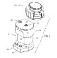
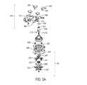
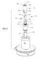
図1〜図3は、本発明の骨清浄・粉砕システム100の基本的なコンポーネントを示している。システム100は、骨清浄モジュール602が取り外し可能に取り付けられる基部102を具備する。骨清浄モジュール602は、採取されたボーンストック(骨ストック、BONE STOCK)を受容する。基部102の作動に際して、清浄モジュール602が取り付けられると、清浄モジュール602の内部のコンポーネントが協調して、ボーンストックに付着した軟部組織を取り除く。図3に見られるように、同じくシステム100の一部であるとともに基部102に対して取り外し可能に取り付けられる第2のモジュールは、粉砕モジュール902である。ボーンストックが清浄された後には、清浄モジュール602が基部102から取り外され、粉砕モジュール902が基部に取り付けられる。清浄されたボーンストックは、清浄モジュール602から粉砕モジュール902へと移送される。再度、アセンブリ基部102が作動する。これにより、粉砕モジュール902の内部のコンポーネントは、清浄されたボーンストックをより小さな骨片へと変換する。骨片は、外科手術における充填材として使用可能である。I. Overview FIGS. 1 to 3 show the basic components of the bone cleaning and crushing
基部102の内部には、モータ140が存在する(図4)。モジュール602または902が基部102に接続されると、モジュールの内部の多くの可動コンポーネントがモータ140に接続される。基部102上のスイッチ588または590を押下することにより、モータ140が作動する。モータ140の作動によって、それぞれ骨を清浄または粉砕するモジュール602または902の内部のコンポーネントが同様に作動する。 A
II.アセンブリ基部
図2および図3を参照して見られるアセンブリ基部102は、基部の外側体であるシェル104を具備する。シェル104は、重力基準面に関して当該シェルの最底部である架台106を有するように形成されている。架台106からは、ネック112が上方に延びている。重力基準面に平行な断面において、ネック112は、面積が架台106より小さい。ネック112の境界は、架台の外周の内方に位置付けられている。シェル104は、架台106の最も広い部分からネック112へと内方にテーパ状の外装パネル108が成形され、当該外装パネル108を架台が有するようにさらに形成されている。II. Assembly Base The
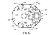
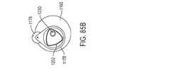
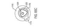
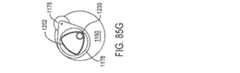
ネック112の上方では、シェル104がヘッド114を有するように成形されている。シェル104は、ヘッド114がネック112から外方に突出するように成形されている。本発明の図示の態様においては、ネック112およびヘッド114の両者が断面において、面取りされた長円の形状となっている。ネックおよびヘッドの湾曲側面はそれぞれ、180°未満の円弧に対する。ヘッド114ひいてはシェル104の最上構造パネルが上部プレート122である。上部プレート122は、ヘッド114の隣接外周から約5mm内方に窪んでいる。上部プレート122は、当該プレート122の平面状の上面の円周方向および下方に延びたリム116を有する。ヘッド114の外面からリムまで内方に延びた段部115は、ヘッド114の外周と上部プレートリム115との間の遷移面として機能する。 Above the
上部プレート122は、図6および図7にて識別される4つの矩形開口118がリム116に存在するようにさらに形成されている。開口118は、上部プレート122の前後縁部に隣接したリム116の部分に位置付けられている。上部プレートの前縁部は、シェルの基部パネル108の上方の縁部であることが了解される。後縁部は、基部パネル108から最も遠い縁部である。 The
また、上部プレート122は、2つの開口124および126を有する。開口124および126はともに、プレート122を横切って左右に延びた長軸上に中心がある。開口124は、プレートを横切る短軸から約1cm離れるように離隔している。短軸は、パネル前縁部の中点からパネル後縁部の中点まで延びた軸である。開口126は、開口124に最も近い側に対してプレート短軸の反対側に位置付けられている。開口126は、短軸よりも上部プレート122の隣接湾曲側近くに位置付けられている。また、リム116は、図43においてのみ識別されるスロット119を規定するように成形されている。スロット119は、開口126に隣接して位置付けられたリム116の湾曲側を通って延びている。 The
上部プレート122は、当該プレート122の平面部の下面から下方に突出したスリーブ123、127、および128を有するようにさらに形成されている。スリーブ123は、開口124の下側で、プレートの平面部から下方に延びている。スリーブ127および128は、同心であり、開口126の下側で、プレートの平面部から下方に延びている。スリーブ127は、最も内側のスリーブであって、開口126から内方に延びたボア(識別せず)を規定している。スリーブ128は、最も外側のスリーブであって、スリーブ127から半径方向外方に離隔している。上部プレート122は、スリーブ128がスリーブ127よりも上部プレート122から下方に突出するようにさらに形成されている。また、上部プレート122の下面からは、多くのポスト129が下方に突出しており、2つのポストを識別している。ポストの自由端は、ボア(識別せず)を有するものとして示している。これらのボアは、以下に論じる締結具を受容するために存在する。 The
シェル104の内側には、2つの支持部材が静的に取り付けられている。支持部材のうちの第1の支持部材は、図4においてのみ見られるモータマウント132である。モータマウント132は、形状が大略板状であり、架台106に対して比較的近くなるように、ネック112中に取り付けられている。モータマウント132には、大きな貫通孔134が形成されている。 Two support members are statically attached to the inside of the
第2の支持部材である内側プレート150は、シェルヘッド114中に配設されている。内側プレート150の外周が固定されるシェルの内部の段部については、識別していない。図8において最もよく見られる通り、プレート150は、平面基部152を有する。プレート150は、基部152の開口から下方に延びた2つの空間156および162を有するようにさらに形成されている。内側プレート150は、空間156の形状が丸みを帯びた頂点を有する大略三角形状となるように成形されている。内側プレート150は、空間156が上部プレート開口126の下側に位置付けられるように形成されている。空間156の基部は、基部152の下側に位置付けられたパネル160によって規定される。空間156の境界は、基部から下方に延びてパネルを基部に接続するウェブ158が規定している。空間162は、上部プレート開口124と同軸になるように位置付けられている。空間162の基部は、プレート基部152の下側に位置付けられたボス166が規定している。プレート基部152とボス166との間に延びたプレート150の一部でもあるウェブ164がプレート150のその他の部分にボスを保持するとともに、空間162の外周を規定している。 The
モータマウント132および内側プレート150はともに、ボアおよび有底ボアによって、多くの開口を有するように見られる。開口およびボアのいくつかは、カウンターボアによって囲まれている。これらのボアのいくつかは、モータマウント132およびプレート基部152の上側面から上方に延びた円形アイランドから下方に開放されている。これらの開口、ボア、カウンターボア、およびアイランドについては、識別していない。これらのボアおよびカウンターボアは、モータマウント132および内側プレート150に対してアセンブリ基部102の後述のコンポーネントを保持するピンおよび締結具を受容することが了解されるものとする。内側プレート150の開口のいくつかは、上部プレート122から下方に延びたポスト129と一致するように位置決めされている。内側プレート150の開口を通ってポスト129の隣接ボアへと延びた締結具(図示せず)は、内側プレートをポスト129に保持する。このように、ポスト129が内側プレート150を上部プレート122に接続するため、プレート122および150に取り付けられたコンポーネントを含むこのサブアセンブリは、単一ユニットとしてシェル104に嵌合することができる。 Both the
モータ140は、モータマウント132の下側面に取り付けられている。そして、締結具(図示せず)がモータ140をマウント132に保持する。モータ140は、図10の断面においてのみ見られるように、マウント132を通って延びる開口を通って延びたシャフト142を有する。シャフト142が延びる開口は、直径がシャフトよりも大きい。モータ140は、モータシャフトがシェル上部プレート122の開口124と同軸になるように、シェル104中に取り付けられている。 The
モータシャフト142は、歯車列144に接続されており、その外側シェルを図示している。歯車列144は、モータマウント132の内部の開口134に固定されて、開口134の直下のモータ140の部分上に配設されている。歯車列144は通常、モータシャフト142の回転運動の速度を落とす遊星歯車アセンブリから成る。歯車列の回転運動は、当該歯車列の外側シェルから上方に延びたシャフト145を通じて出力される。本発明の一態様において、モータ140は、作動時に、モータシャフト142の速度が2500〜5500RPMで回転するように設計されている。歯車列144は、モータシャフト142と歯車列シャフト145との速度比が5:1〜90:1となるように構成されている。 The
歯車列144の基部は、モータ140のハウジングの面に直接取り付けられている。これにより、歯車列144の基部は、モータシャフト142が延びるモータマウント132の開口中に固定されている。歯車列144の上面は、プレート152と一体化したボス166の下面に取り付けられている。本発明の図示の態様においては、歯車列144の上部とボス166の下面との間にプレート151が位置付けられている。プレート151は、モータの振動を和らげるため、エラストマ材料で形成されていてもよい。そして、プレート151を通って歯車列の上部へと延びた締結具147(図4においては1つを識別)がプレートを歯車列に保持する。歯車列144は、ボス166の開口を通って延び、プレート150の内部の空間162へと延びたシャフト145を有する。歯車列シャフト145は、形状が大略円筒状である。シャフト145の円筒面からは、キー146(図9にて識別)が外方に延びている。キー146は、シャフト145に沿って長手方向に延びている。 The base of the
図9および図10において最もよく見られる軸170は、歯車列シャフト145に取り付けられて、シャフト145とともに回転する。軸170には、円筒状の基部172を含む。基部172からは、円筒状の胴体176が上方に延びている。胴体176は、基部172と同軸であるが、基部よりも直径が小さい。胴体が基部172から現れる位置に隣接して、胴体周りに延びる段部174を有するように軸170が成形されている。胴体176の上方において、軸は、ネック180を有する。ネック180は、胴体176と同軸であるが、胴体176よりも直径が小さい。これにより、ネック180の底部から半径方向外方に、段部178が円周方向に延びており、胴体176とネック180との間の遷移面として機能する。軸の最上部は、ヘッド182である。ヘッド182は、軸ネック180と同軸であるが、軸ネック180よりも直径が小さい。 The
軸170は、基部172の底部から上方に延びた有底ボア184を有するようにさらに形成されている。ボア184は、基部172と同軸である。軸ネック180の外面からは、窪み186が内方に延びている。軸170は、ボア188が軸ヘッド182を通って長手方向に延びるようにさらに形成されている。本発明の図示の態様において、ボア188は、窪み186を通って軸170の長手方向軸まで内方に延びた放射状の中心線に垂直な軸上に中心がある。 The
軸170は、歯車列144上に固定されており、歯車列シャフト145は、軸ボア184中に固定されている。キー146は、ボア184の外周から外方に延びた軸の内部のスロット185に固定されている。このスロット構成のキーにより、歯車列シャフト145および軸170は、単一のユニットとして回転する。 The
軸胴体176の周りには、歯車190が配設されて、軸170とともに回転する。歯車170は、段部174に載っている。歯車190の歯は、軸基部172の上方および段部174の半径方向外方の両者に位置付けられている(歯車の歯は図示せず)。 A
軸170には、主結合器194が取り付けられている。主結合器194は、円筒状の基部196を含む。基部196の上部からは、ピン198が上方に延びている。また、基部196の上部には、円周方向に等間隔で離隔した3つの歯202が配設されている。各歯202は、ピン198から半径方向外方に突出するとともに基部196の上部から上方に延びた細長部材である。主結合器194は、ピン198が歯202の上方に突出するように形成されている。 A
主結合器194は、基部196の底部から上方に延びたボア(穴、孔)204を有するようにさらに形成されている。ボア204は、軸ヘッド182の密な滑合を可能にする直径を有する。ボア204は、基部196の上部に向かって延びた有底ボア206へと開放されている。主結合器194は、ボア(穴、孔)206の直径がボア204の直径より小さくなるように形成されている。より詳細に、結合器194は、ボア206の直径が軸170のヘッド182の直径より小さくなるように形成されている。結合器194は、基部196の円筒状外面から内方に延びた2つの正反対の長円状開口208を有するようにさらに形成されている(図10においては、一方の開口208が見られる)。開口208は、ボア204に延入している。 The
主結合器194は、軸ヘッド182が結合器ボア204中に配設されるように、アセンブリ基部102のその他の部分に嵌合されている。また、結合器開口208を通って軸ヘッド182の内部のボア(穴、孔)188へとピン210が延びている。ピン210は、主結合器194が軸170とともに回転し、軸の長手方向軸に沿って長手方向に移動し得るように、結合器を軸に保持する。主結合器は、結合器基部196の上部が上部プレート開口124を通って延びるように位置決めされている。結合器ピン198および歯202は、シェルの上部プレート122の上方に位置付けられている。 The
結合器ボア206には、図5Aに見られるバネ212が配設されている。バネ212は、結合器を垂直方向に変位させて、結合器ピン198および歯202をシェルの上部プレート122から離隔させる付勢力を与える。結合器194の上方移動は、ピン210に隣接する開口208の底部を規定する結合器の部分によって制限されている。結合器の下方移動は、ボア204から軸ヘッド182の上部に隣接するボア208への遷移を規定する結合器の内部の段部によって制限されている。 The coupler bore 206 is provided with a
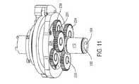
軸170のネック180の周りには、副歯車列220(そのコンポーネントは、図5A、図5B、および図11において最もよく見られる)が配設されている。副歯車列220は、内側プレート150の内部の空間162に配設されたリング歯車222を含む。歯車222は、外面がウェブ164の内面に対して配設されるように位置決めされている。リング歯車の歯(歯は識別せず)は、空間162の中心に向かって内方に延びている。リング歯車222の外周の周りおよび上方に配設されたスナップリングについては、図示していない。スナップリングは、ウェブ164の溝から外方に突出する。スナップリングは、空間162においてリング歯車222を保持する。 Around the
また、歯車列220は、第1の組の遊星歯車224を含む。歯車224は、ピン225によって、担体226に回転可能に取り付けられている。歯車224は、歯車190およびリング歯車222の歯の両者に係合する。担体226は、軸170のネック180を囲む太陽歯車228をそれ自体で有する。太陽歯車228の内径は、軸170から半径方向外方に離隔している。 The
同じく副歯車列220の一部である3つの遊星歯車230がリング歯車222と太陽歯車228との間で延びている。遊星歯車230は、ピン231によって、後述のアームカム234に回転可能に取り付けられている。副歯車列は、軸の回転速度よりも遅い速度でアームカムおよび取り付けられるコンポーネント(構成要素)が回転するように設計されている。本発明のいくつかの態様において、軸170とアームカム234との速度比は、12:1〜24:1である。 Three
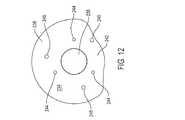
図12において最もよく見られるアームカム234は、大略ディスク状のコンポーネントである。アームカム234には、中心開口236が形成されている。開口236は、軸ネック182よりも大きな直径となるように寸法規定されている。アームカムは、2つのローブを有する。外側ローブ238は、カム234の中心から比較的遠くに離隔した外周を有する。外側ローブ238は、カム234の外側周りで180°よりも大きく伸びた円弧に対する。本発明のいくつかの態様において、外側ローブは、190〜240°の円弧に対する。第2のローブは、内側ローブ242である。内側ローブ242は、外側ローブ238の外周から半径方向内方に離隔した外周を有する。内側ローブ242は、カム234の周りの20〜60°の角度に対する。外側ローブ238の各端と内側ローブ242の隣接端との間の遷移面については、識別していない。 The most commonly seen
アームカム234には、当該カムを通って左右に延び、開口236から半径方向外方に離隔した2組の貫通ボアが形成されている。第1の組のボアは、円周方向に等間隔で離隔した3つのボア244である。ボア244は、アームカムに対して遊星歯車230を回転可能に保持するピン231を受容する。第2の組のボアは、円周方向に等間隔で離隔した3つのボア245である。ボア245は、直径がボア244よりも大きく、ボア244から角度オフセットしており、ボア244から半径方向外方にわずかに離隔している。ボア245は、後述のチューブカム252をアームカム234に保持する締結ピンを受容する(締結ピンは図示せず)。 The
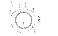
ここで図13および図14を参照して説明するチューブカム252は、アームカム234に取り付けられている。チューブカム252は、リング状のスカート254を含む単一のコンポーネントである。スカート254の上方にはリム256が配設され、スカートから半径方向外方に延びている。チューブカム252は、リム256が内側および外側ローブ258および262をそれぞれ有するように形成されている。内側ローブ258は、半径方向距離に関して、カムの中心に比較的近く位置付けられた外面260を有する。内側ローブ258は、カム252の周りで180°よりも大きな円弧に対する円弧に対する。本発明のいくつかの態様において、内側ローブ258は、185°〜205°の円弧に対する。外側ローブ262は、内側ローブ252の表面260よりもカム252の中心軸から遠くに位置付けられた外面264を有するように成形されている。チューブカム252は、カムの中心周りでカム表面264が40°〜140°の円弧に対するように形成されている。外面260と外面264との間の遷移面については、識別していない。 The
チューブカム252は、スカート254およびリム262が一体として、カムの中心を通って延びた開口266を規定するように形成されている。チューブカムは、開口266中へと突出するとともに開口266の周りで円周方向に延びた段部268を規定するようにさらに形成されている。段部268は、リム262の上面の下側に位置付けられている。スカート254の底部から段部268の上部へは、図14において識別される円周方向に等間隔で離隔した3つのボア270が延びている。基部102の組み立てに際して、チューブカムのボア270は、アームカムのボア245に対して位置決めされる。ボア270は、切削カム252をアームカム234に保持する締結ピンを受容する。 The
図15において最もよく見られるように、アームカム234とチューブカム252との間には、平衡カラー246が挟まれている。平衡カラー246は、中心リング247を含む。アセンブリ102は、リング247により規定された空間にスカート254が配設されて空間内で回転するように構成されている。中心リング247からは、4つのタブ248(図15においては2つが見られる)が外方に突出している。また、タブ248それぞれを通って、締結具249(3つの締結具を識別)が延びている。締結具249は、内側プレート150の基部152に固定されている。これにより、締結具249は、アセンブリ基部102に対して平衡カラー246を静的に保持する。タブ248および締結具249は、アームカム234の半径方向外方に位置付けられている。このため、静的な平衡カラー246が存在していても、アームカム234およびチューブカム252の回転は妨げられない。 As is most often seen in FIG. 15, a
チューブカム252の上方には、図16〜図18において最もよく見られるクラッチアセンブリ278が軸170周りに配設されている。図16および図18において、アームカム234、切削カム252、およびアームカム234の下側の歯車アセンブリは、簡素化のため示していない。 Above the
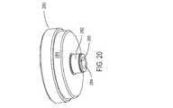
クラッチアセンブリ278は、入力リング280を含む。図19および図20において最もよく見られる入力リング280は、管状の軸282を有する。軸282は、貫通ボア284が形成されており、軸のネック180周りにしっかりと嵌合するように寸法規定されている。ボア284を規定する軸282の内面からは、スロット285が外方に延びている。このため、スロット285は、ボア284に連続している。入力リング280は、軸282の上部から半径方向外方に延びたヘッド286を有するようにさらに形成されている。ヘッド286は、その外面から外方に突出したリング(識別せず)を有するものとして示している。このリングは、機械的強度を入力リング280に与える。ヘッド286は、その中心に円筒状の空間288を規定するように形成されている。空間288は、軸282を通って延びたボア284に連続しており、これよりも直径が大きい。ヘッド286は、ボア284への開口を囲む凹面290を有するようにさらに形成されている。 The
入力リング280は、リング軸284が軸ネック180上に配設されるように、軸270に嵌合されている。軸284は、アームカム234の開口236内に配設されている。リングヘッド286の下部は、チューブカムの開口266内に配設されている。軸ネック180からは、図18においてのみ識別されるキー181が外方に延びている。キー181は、入力リング280の内部のスロット285中に固定されている。このスロット内キー構成により、軸170およびクラッチ出力リングは、単一のユニットとして回転する。 The
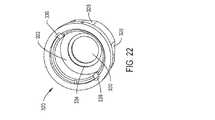
入力リングの空間288には、同じくクラッチ278の一部である出力リング320(図21および図22において最もよく見られる)が配設され、入力リング280の上方に突出している。出力リング320は、円形の基部322を有する。基部322の外周からは、大略管状のスリーブ324が上方に延びている。スリーブ324の内面および外面は、大略円筒形状であるが、完全に円筒状ではない。出力リング320は、スリーブ324の外面に沿って円周方向に等間隔で離隔した4つの平面326を規定するように形成されており、図21および図22においては、2つの平面を識別している。平面326は、スリーブ324の湾曲外面により規定された円形領域内に位置付けられている。外側リング320を通る上下長手方向軸に対して、各平面326は、50°〜90°の角度に対する。外側リング320は、スリーブ324の上方に配設された円形のリップ部328を有するようにさらに形成されている。リング320は、リップ部328がスリーブ324の外面を越えて半径方向外方に突出するように形成されている。 In the
出力リング320は、基部322に開口330が存在するようにさらに形成されている。また、アセンブリ基部102が組み立てられた場合に、軸ヘッド182の外面と開口330の外周を規定するリング基部322の表面との間に間隙が存在するように、開口330は十分な直径を有する。スリーブ324およびリップ部328は一体として、開口330に連続する空間332を規定している。基部322は、その上面に凹面334を有するようにさらに形成されている。凹面334は、開口330の周りで円周方向に延び、空間332の最も低い部分を規定している。 The
出力リング320は、スリーブ324およびリップ部328の内面から半径方向外方に延びた2つの切り欠き336を有するようにさらに形成されている。切り欠き336は、リング320の上面からリングを通り、一部がスリーブ324を通って長手方向に延びている。切り欠き336は、外側リング320を通る長手方向軸に対して、互いに正反対である。外側リングは、リップ部328の内周の周りで内方に延びた段部338を規定するようにリップ部が成形されるようにさらに形成されている。段部338は、リップ部328の上側面の下側に位置付けられている。切り欠き336は、段部338と交差する。 The
図21においてのみ識別される2つの同軸ボア335が出力リング320のリップ部328を通って横方向に延びている。ボア335は、段部338と交差する。クラッチ278が組み立てられると、ピン339がボア335それぞれにおいて固定される。各ピン339は、出力リング320のリップ部328の隣接円筒面から半径方向外方に位置付けられたヘッドを有する。 Two
入力リング280と出力リング320との間には、図23および図24において最もよく見られるケージ294(同じくクラッチ278の一部である)が配設されている。ケージ294は、リング296を具備する。リング296からは、大略管状のスカート298が下方に延びている。ケージ294は、スカート298の内面がリング296の内面と同一平面となるように形成されている。スカート298の外面は、リング296の外周から半径方向内方に位置付けられている。ケージは、円周方向に等間隔で離隔した4つのスロット302(2つのスロットを識別)がスカート298中に存在するようにさらに形成されている。各スロット302は、スカート298の基部から上方に延びており、スカートの端部は、リング296に隣接する端部の反対側である。各スロット302は、ケージ294を通る上下長手方向軸に平行な長軸に沿って中心がある。ケージ294は、スカート298がリング296から下方に延びた位置の下側に離隔した位置でスロット302が終端するように形成されている。 Between the
ケージ294は、リング296の外周からタブ304が外方に突出するようにさらに形成されている。リング296の上側面からは、図23において識別される2つのピン306が上方に延びている。ピン306は、ケージ294を通る長手方向軸に対して、互いに正反対である。ピンが固定されるリングの上面の有底ボアについては、識別していない。 The
本発明のいくつかの態様において、ケージ294は、一体的な組み立てにより単一のユニットとして機能する2つのコンポーネントで形成されている。これにより、製造プロセスにおいて、ピン306に対するタブ304の選択的位置決めが容易となる。 In some aspects of the invention, the
クラッチ270が組み立てられた場合、出力リング320は、入力リング280の空洞288中に固定される。出力リングの基部322は、入力リング280の凹面290上に固定された低摩擦ワッシャ293に固定されている。ワッシャ293が存在することにより、出力リング320に対する入力リング280の相対的な回転移動が容易となる。ケージスカート298は、入力リング280のヘッド286と出力リングのスリーブ324との間に配設されている。スカートの各スロット302は、出力リングスリーブの外面に形成された平面326のうちの1つに隣接している。クラッチを構成するコンポーネントは、入力リング280および出力リング320の両者に対してケージ294が回転し得るように寸法規定されている。 When the clutch 270 is assembled, the
クラッチケージ294に形成されたスロット302にはそれぞれ、円筒状のピン305が配設されており、図17および図25においては、2つのピンを識別している。ピン305は、ケージスカート298の壁厚よりも小さな共通の直径を有する。このため、各ピン305は、スカート298から、出力リング320に形成された隣接平面326に向かって内方に突出している。 A
各ピン306と隣接ピン339との間には、同じくクラッチ270の一部であるバネ340(図17において1つ識別)が延びており、図16および図17のそれぞれにおいて、1つのバネを識別している。バネ340は、図25に見られるように、各スロット302が隣接平面326の端部に隣接するようにケージを垂直に保持する。ケージ294がこの配向となった結果、各ピン305は本質的に、入力リングヘッド286の内面と隣接平面326との間でくさび留めされる。図25に示す状態で入力リング280が反時計回りに回転すると、ピン306は、ケージ294および出力リング320の両者にこの回転を伝える。そして、出力リング320が回転すると、クラッチ278は、係合状態になるものと考えられる。 A spring 340 (identified one in FIG. 17), which is also part of the clutch 270, extends between each
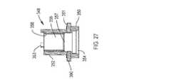
クラッチ278は、ここで図26および図27を参照して説明する管結合器348を駆動する。管結合器348は、円筒状の架台350を具備する。架台350は、上部プレート開口124の下側のスリーブ123の内径よりも大きな外径を有する。また、架台の外径は、出力リング320のスリーブ324の円筒状内面により規定された空間332に架台が滑合し得るようになっている。架台350からは、管状のヘッド352が上方に延びている。結合器架台350とヘッド352との間の遷移は、円形の段部351が規定する。ヘッド352の円筒状内壁の周りには、スリーブ状の低摩擦ブッシュ358が配設された様子を示している。結合器ヘッド352の円形状の上面からは、円周方向に等間隔で離隔した3つの歯353が上方に延びており、1つの歯を識別している。 The clutch 278 drives the
管結合器348は、架台350の底部から上方に延びたボア354を有するように形成されている。ボア354への開口を構成するテーパ状のカウンターボアについては、識別していない。ボア354は、ボア356へと開放されている。ボア356は、ボア354と同軸であるが、ボア354よりも直径が小さい。ブッシュ358は、ボア356を規定する結合器ヘッド352の内面に対して配設されていることが了解される。また、小さなリップ部357がボア356中へと突出している。リップ部357は、結合器ヘッド352の底部近くに位置付けられている。リップ部357は、ボア356においてブッシュ358を支持する管結合器の構造的特徴である。 The
結合器架台350の対向部からは、軸方向に整列する2つのピン390が半径方向外方に延びている。ピンが固定される架台の内部のボアについては、識別していない。ピン390は、出力リング320の内部の切り欠き336に固定されるように寸法規定されている。出力リングの切り欠き336におけるピン390の固定の結果、管結合器がクラッチ278に接続され、出力リング320とともに回転するとともに、リング320に対して長手方向に移動する。 Two
アセンブリ基部102は、シェルの上部プレート122と一体化したスリーブ123において、管結合器348が回転するとともに長手方向に移動し得るように構成されている。出力リング320の凹面334とボア354およびボア356間の管結合器の内部の段部との間には、図17および図18において識別されるバネ394が延びている。バネ394は、管結合器348を付勢するため、歯353がシェルの上部プレートから垂直に離れる方向に付勢される。スリーブ123の被覆端に対して、結合器架台350の上方に外部段部351が隣接することにより、管結合器348の上方移動が制限される。 The
主結合器194は、ブッシュ358を通って延びている。基部102のコンポーネントの寸法規定およびブッシュ358の低摩擦性により、主結合器194は、ブッシュに対して回転するとともに、ブッシュ内で長手方向に移動し得る。 The
図28および図29において最もよく見られる歯止め396がクラッチケージ294の回転を選択的に阻止することにより、係合状態と非係合状態との間でクラッチ270を遷移させる。歯止め396は、湾曲した長手方向軸を有するように形成された本体398を有する。本体398の隅部は、丸みを帯びている。歯止め本体398は、本体に沿って長手方向に延びた溝402を有するようにさらに形成されている。溝402は、チューブカム252から離れる方向の本体側である本体398の外側から内方に延びている。溝402は、本体398の一端に開口を形成するが、この開口は識別していない。溝402は、開口を構成する本体の端部から延びると、深さが減少する。歯止め本体398は、切り欠き404を有するようにさらに形成されている。切り欠き404は、溝402が延びる本体の端部の反対側の端部に位置付けられている。重力基準面を参照することにより、切り欠き404は、溝402の下側に位置付けられる。 The most
歯止め本体398は、本体を通って上下に延びた2つのボアを有するようにさらに形成されている。第1のボア406は、溝402が延びる本体の端部に隣接して、本体を通って延びている。ボア406は、溝402と交差する。第2のボア408は、ボア406が形成された端部と反対の本体端部の内方に位置付けられている。ボア408は、切り欠き404と交差する。 The
歯止め396は、フィンガ410を有するようにさらに形成されている。フィンガ410は、本体398の内側から外方に延びている。歯止め396は、フィンガ410が切り欠き404の上方に位置付けられるように形成されている。 The
歯止めの切り欠き404には、ローラ412が配設されている。ローラ412は、ボア408中に固定されるとともにローラを通って延びたピン414により、歯止め本体に対して回転可能に保持されている。 A
歯止め396は、内側プレート150の基部152から上方に延びたピン416に対して枢動可能に取り付けられている。図5Bにおいてのみ見られるスペーサ417が歯止めを基部152の上方に保持する。本発明の図示の態様において、ピン416は、スペーサ417を通って延びる。スペーサ417は、内側プレート150に取り付けられ、当該プレートに対して静的となっている。 The
溝402には、図29においてのみ見られる捩りバネ418が固定されている。より詳細に、バネ418の螺旋中心部は、歯止めの溝402を通って延びたピン416の部分の周りに固定されている。溝の基部を規定する歯止め本体398の表面に対しては、捩りバネ418の1つの脚部が配設されている。捩りバネ418の対向脚部は、内側プレートウェブ164の隣接面に支えられている。 A
スペーサ417が存在することにより、チューブカム252と同じ平面になるように歯止めローラ412が位置付けられるように、歯止め396が位置決めされている。歯止めフィンガ412は、クラッチ270と一体化したタブ304が回転する同じ平面にある。捩りバネ418は、チューブカム252の外面に対してローラ412を押し付ける歯止めの力を加える。アセンブリ基部102を構成するコンポーネントは、ローラ412がカムの内側ローブ258に乗り上げた場合に、タブ304が回転する空間にフィンガ410が配設されるように寸法規定されている。カムの回転により外側ローブ262がローラ412に対して回転すると、カム252の力がバネ422の力を超える。歯止め396は、ピン416の周りを枢動する。この枢動の結果として、フィンガ410は、タブ304が回転する空間から離れる方向に移動する。 Due to the presence of the
歯止め398がタブ304から離隔すると、バネ340がクラッチケージにトルクを与えて、図25に示す位置にケージを保持する。具体的に、ピン305は、平面326に隣接して保持される。ピン305は、入力リング280と出力リング320との間に位置決めされているため、これら入力リングおよび出力リングという2つのコンポーネント間でくさび留めされる。このため、ピン305は、回転運動が阻止される。また、ピン305は、入力リング280のヘッド286の円筒状内面と摩擦接触することが了解される。図25の視点から見て、入力リング280が反時計回りに回転すると、摩擦接触のため、入力リング280の回転がピン305に伝わる。このため、ピン305は、入力リングとともに回転する。ピン305は、出力リング320に対してくさび留めされていることから、出力リングも同様に、反時計回りに回転させる。クラッチは、この状態にある場合、係合状態となる。 When the
アセンブリ100の動作中には、図30に見られるように、クラッチケージ294と一体化したタブ304を歯止め398が押圧するタイミングが存在する。このように歯止めがタブに隣接する結果、クラッチケージは、さらなる回転が阻止される。これによっても、出力リング320に対するピン305の回転がシフトする。具体的に、ケージ294およびピンは、内側の出力リング320に対して、図25に見られる回転配向の時計回りの回転配向へと移動する。その結果、ピンは、出力リングに対してくさび留めされなくなる。ピン305は、このように回転している場合、入力リング280の回転移動を出力リング320に伝えることはない。クラッチは、非係合状態である。 During the operation of the
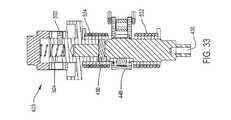
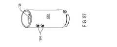
また、アセンブリ基部102は、ケージドライバ420を具備する。ケージドライバ420は、清浄モジュール602の内部のケージ764を枢動させる。ケージドライバ420は、図35において最もよく見られるシャフト422を具備する。シャフト422は、直径が異なる多くの同軸部を備えた単一のコンポーネントである。シャフト422の底部には、足部424が存在する。足部424は、その円筒状外面の内方に位置付けられた2つの平行平面423(一方を図示)を有するように形成されている。足部424の直上には、胴体428が位置付けられている。胴体428の直径は、足部424の直径よりも大きい。胴体430の一部の円周方向かつ半径方向外方には、同じくシャフト422の一部であるカラー430が延びている。シャフト422は、その中位のわずか上方の位置を始点として、胴体428がシャフトから外方に延びるように形成されている。カラー430の上部は、胴体428の上部の下側に位置付けられている。シャフト422は、胴体428から上方に延びたヘッド432を有するようにさらに形成されている。 The
足部424の底部からは、有底ボア436が上方に延びている。平面423およびボア436が存在することにより、基部102の組み立ておよび分解が容易化されるが、存在しなければ本発明には関係ない。 A bottomed
シャフト422は、当該シャフトを通って左右に延びた長円状の細長中空438を有するようにさらに形成されている。中空438は、シャフト422を通る上下長手方向軸に垂直な長軸上に中心がある。シャフト422は、中空438がカラー430の高さ方向全体にわたって延びるように形成されている。また、中空438は、カラー430の上下に延びたシャフト胴体428の部分へと短い距離だけ延入している。中空438は、有底であり、胴体428およびカラー430を通って横方向には延びていない。シャフトには、円形の貫通ボア440がさらに形成されている。ボア440は、シャフトヘッド432に形成され、胴体428の直上に位置付けられている。ボア440は、シャフト422を通る長手方向軸に垂直でこれと交差する軸上に中心がある。 The
シャフト422が基部102に配設されているため、足部424および胴体428は、内側プレート150の一部であるパネル160を通って延びている。足部および脚部424は、パネル160に形成された同心開口を通って延びている。脚部424およびプレート150の表面を規定する隣接開口の周りには、アセチル等の低摩擦材料で形成されたブッシュ444が延びている。ブッシュ444は、シャフト422の回転を容易化する。 Since the
シャフト422から外方に延びたクランク448がシャフト422の回転配向を設定する。クランク448には、円形リング450を含む。リング450は、シャフト422と一体化したカラー430上にクランクをしっかりと嵌合し得る内径を有する。リング450から半径方向外方には、2つの離隔した平行重畳タブ454が延びている。 A
クランク448は、リング450が2つの対向凹段部452を有するようにさらに形成されている。段部452は、リング450の対向上下面に対して内方に窪んでおり、リングを通って軸方向に延びた中心貫通開口454を囲んでいる。クランク448は、スロット456を有するようにさらに形成されている。スロット456は、開口454を規定するリングの円筒状内面から半径方向外方に延びている。このため、スロット456は、中心開口454に連続している。クランク448は、スロットが段部452の表面と交差するように形成されている。クランクタブ454にはそれぞれ、タブを通って延びた開口458が形成されている。これらの開口458は、タブ458の外端のわずか内方に位置付けられている。開口458は、同軸である。 The
クランク448は、シャフトの内部の中空438とクランクスロット456が一致するように、シャフト422の周りに固定されている。中空438からスロット456までは、キー460が延びている。これにより、キー460は、クランク448をシャフト422に保持して、これら2つのコンポーネントが単一のユニットとして回転するようにしている。 The
シャフトヘッド432上には、ハット464が配設されている。図36および図37に見られるように、ハット464は、円筒状のコア468を有する。コア468の半径方向外方かつ円周方向には、鍔が延びている。鍔は、コアから半径方向外方に延びた鍔の部分である内側部分469を有する。鍔の内側部分469は、コアを通る上下長手方向軸に垂直な平面内に存在する。ハット464は、コア468の長さ方向に沿った略中間の位置から、鍔の内側部分が外方に延びるように形成されている。鍔は、内側部分の外周から上方に延びた外側部分470を有する。ハット464は、シェルの上部プレート122と一体化したスリーブ127の内径よりも鍔の外側部分470の内径がわずかに大きくなるように形成されている。 A
ハット464は、コア468の底部から上方に延びた有底ボア472を有するように形成されている。コア468は、2つの正反対の切り欠き474を規定するように形成されている。切り欠き474は、コア468の底部から上方に延びている。各切り欠き474は、ボア472へと開放されている。ボア472は、シャフト432が滑合し得るように寸法規定されている。ハットコア468には、第2のボアとして有底ボア476が形成されている。ボア476は、コア468の上部から下方に延びている。ハットは、鍔の内側部分469の外側部に対して窪んだ表面478が鍔の内側部分の上側部に形成されるように形成されている。この凹面478は、コア468を囲むことが了解される。鍔の上方において、ハット464は、コア468まで延びた2つの正反対の開口477を有するように形成されている。各開口477は、ボア476に延入している。 The
ハット464がシャフト422のヘッド432上に配設されているため、ヘッド432は、ハットボア472に配設され、ハットボア472中で回転可能である。ハット464の底部であるコア468の底面は、シャフト胴体428とヘッド432との間の遷移面である段部に固定されている。シャフトヘッド432の内部のボア440には、ピン480が固定されている。ピン480の両端は、シャフト422から半径方向外方に突出して、ハット464の基部に位置付けられた切り欠き474中に固定されている。ハットの切り欠き474にピン480が存在することにより、ハット464は、シャフト422の周りである程度の回転が可能となる。本発明のいくつかの態様において、アセンブリ基部を構成するコンポーネントは、ハットがシャフトの周りで5°〜45°回転し得るように構成されている。 Since the
鍔の内側部分469からは、図34においてのみ見られるピン479が下方に延びている。ピン479は、ハット464のコア468から半径方向外方に離隔している。ピン479の上部が圧入されるハット464のボアについては、図示していない。 From the
ハット464上には、同じくケージドライバ420の一部であるアーム結合器486が配設されている。図38および図39において最もよく見られるアーム結合器486は、円筒状の基部488を含む。アーム結合器の基部488は、ハット464の凹面478の直上の空間に固定し得る外径を有する。基部488の上部の上方には、同じくアーム結合器486の一部である円形ボス490が立ち上がっている。アーム結合器486は、ボス490の外径が基部488の外径より小さくなるように形成されている。ボス490の上面の上方には、ボスと一体化したバー492が立ち上がっている。バー492は、平行な対向側面を有する。バーは、ボスを横方向に延びて、基部488およびボス490の上下共通長手方向軸と交差する。 On the
アーム結合器486は、基部488の底面から上方に延びた有底ボア494を有するようにさらに形成されている。アーム結合器486は、ハットコア468の滑合を可能にする直径をボア494が有するように形成されている。また、アーム結合器486は、基部488の外面から内方に延びた2つの正反対の開口496を有するように形成されている。開口496は長円状であり、アーム結合器486に形成されて、結合器を通る長手方向軸に平行な長軸を有する。開口496はそれぞれ、ボア494へと開放されている。 The
ケージドライバ420が組み立てられると、アーム結合器486は、ハットコア468上に固定される。ハット464と一体化したボア477のうちの少なくとも1つにピン502が固定されて、ハットのコア468から外方に延びる。ピン502は、アーム結合器486の内部の開口496のうちの1つに延入している。この開口内ピン構成によって、結合器486がハット464に保持されるため、結合器は、ハットとともに回転するほか、ハットに対して長手方向に移動可能である。ハットボア476には、バネ504が固定されて、ハット464上で上方に延びている。バネ504は、結合器ボア494に延入して、ボア494の閉端を規定する結合器486の内面を押圧する。バネ504はこのようにして、対抗する力がない場合に、アーム結合器をそのハット464に対する配設で保持する力をアーム結合器486に加える。 Once the
ロッカーアーム508がクランク448を枢動させることにより、ケージドライバ420を同様に枢動させる。図41に最もよく見られるように、ロッカーアーム508は、大略細長ビームの形状である。本発明の図示の態様において、アームは、大略中実の第1の部分510を有する。ビームの第1の部分510にスロット512が形成されて、ロッカーアーム508の外端から内方に延びている。アームの第1の部分510の対向端は、その他の部分よりも断面幅がわずかに大きい。ロッカーアームは、第1の部分510から外方に延びた第2の部分514を有する。より詳細に、アームの第2の部分514は、スロット512が形成された端部の反対側の第1の部分510の端部から外方に延びている。ロッカーアーム508は、アームの第1の部分510を通る長軸に対して、アームの第2の部分514を通る長軸がある角度となるように形成されている。また、本発明の図示の態様において、ロッカーアーム508は、アームの第2の部分514の底面がアームの第1の部分510の隣接底面の上方となるように成形されている。アームの第2の部分514の上面は、アームの第1の部分510の隣接上面の下側である。 The
アームの第1の部分510を通って、2つのボア516および518が上下に延びている。ボア516は、アームの第2の部分514から離隔した第1の部分510の端部である部分510の自由端のすぐ内方に位置付けられている。ボア516は、スロット512と交差する。ボア518は、アームの第2の部分514に隣接するアームの第1の部分510の端部を通って延びている。ロッカーアーム508は、細長スロット520がアームの第2の部分514を通って上下に延びるようにさらに形成されている。 Two bores 516 and 518 extend up and down through the
ロッカーアーム508の内部のスロット512には、ローラ524が取り付けられている。スロット512の両側のボア516の部分に端部が固定されたピン522により、ローラ524がロッカーアーム508に対して回転可能に保持される。アセンブリ基部102を構成するコンポーネントは、ローラ524の外面がロッカーアーム508の境界を越えて突出するように配置されている。 A
プレートの基部152の上面の直上の内側プレート150に対しては、図34において識別されるピン526がロッカーアーム508を枢動可能に保持する。ピン526は、内側プレート150に形成された開口のうちの1つに固定されている。ロッカーアーム508が内側プレート150に取り付けられると、ローラ524は、アームカム234のローブ238および242の外面を押圧することができる。 With respect to the
ロッカーアーム508が内側プレート150に取り付けられると、アームの第2の部分514は、クランク448と一体化したタブ454間に位置付けられる。クランクタブ454およびアームスロット520を通って延びたピン530がクランク448をロッカーアーム508に結合する。本発明の図示の態様において、アームスロット520には、ブロック528が摺動可能に配設されている。ピン530は、ブロック528に形成された孔529を通って延びている。ケージドライバ420は、上部に位置付けられたクランクタブ454および底部に位置付けられたクランクタブ454の両者の上方にピン530が突出するようにさらに構成されている。 When the
図33および図34から、ケージドライバ420は、シャフト422の周りに配設された2つの捩りバネ532および534を含むことが分かる。捩りバネ532は、カラー430の下側のシャフト胴体428の部分の周りに配設されている。これにより、バネ532は、プレート150に形成された空間156に固定されている。捩りバネ532の一方の脚部は、クランク448の下側に延びたピン530の部分に押し付けられている。バネ532の対向脚部は、内側プレート150の内部の空間156を規定するウェブ158の部分を押圧する。 From FIGS. 33 and 34, it can be seen that the
第2のバネ534は実際のところ、鍔469の下側のハットコア468の部分の周りに配設されている。バネ534の一端は、クランク448の上方に延びたピン530の部分に対して配設されている。バネ534の対向脚部は、ハット464から延びたピン479を押圧する。これにより、バネ534は、シャフト422上の固定回転配向で、ハット464を垂直に保持する。ハット464が回転可能な範囲は、シャフト422に堅持されたピン480上でハットの切り欠き474が回転し得る範囲によって制限される。 The
本発明の骨清浄器および骨粉砕機の動作においては、バネ532および534によって個別または一体的に、アームカム234に対する相当の横乗せ力をロッカーアーム508が加える。平衡カラー246がこの力に抗する。このため、平衡プレートは、アセンブリ基部内の軸方向に安定した位置でアームカム234ひいてはチューブカム252を保持する。 In the operation of the bone purifier and bone crusher of the present invention, the
アセンブリ基部102の上部プレート122の下面には、図5A、図42、および図43に見られるラッチアセンブリ540が取り付けられている。ラッチアセンブリ540は、最初に清浄モジュール602を解放可能に保持した後、粉砕モジュール902を基部102に保持する。ラッチアセンブリ540は、2つの主プレート542および544を具備する。主プレート542および544は、上部プレート122の下面に取り付けられて、共通の軸周りに枢動する。図中、主プレート542および544はいずれも、共通の締結具539によって上部プレート122の下面に枢動可能に保持されている。締結具539は、主プレート542および544が枢動する軸を規定する。また、上部プレートの下面には、4つの副プレート546が枢動可能に取り付けられており、図42においては、3つの副プレートを識別している。図42においては、副プレートのうちの1つを上部プレート122の下面に保持するとともに副プレートが枢動する締結具547のうちの1つだけを識別している。各副プレート546には、タブ548が形成されている。副プレート546は、上部プレート122の開口118のうちの別個の1つから各タブ548が延びるように、上部プレート122に取り付けられている。副プレート546のうちの2つが主プレート542に結合され、プレート542の枢動に際して移動する。副プレート546のうちの2つが主プレート544に結合され、プレート544の枢動に際して移動する。図5Aにおいては、副プレート546のうちの1つを主プレート542に接続して枢動させるピン545のうちの1つだけを識別している。 The lower surface of the
また、ラッチアセンブリ540は、2つのツマミ562を具備する。ツマミ562は、開口126に最も近い上部プレート122の湾曲外面に隣接して位置付けられている。各ツマミ562からは、ブラケット560が内方に延びている。ブラケット560は、リム116に形成されたスロット119を通って延び、上部プレートの直下の空間に延入している。各ブラケット560は、ブラケットが延びるツマミを主プレート542または544のそれぞれに接続する。図5Aにおいては、ブラケット560を主プレート542および544それぞれに保持する締結具563のうちの1つが見られる。締結具563が延びる主プレート542および544ならびにブラケット560の開口については、識別していない。 The
ラッチアセンブリの主プレート542および544間には、バネ566が延びている。バネ566は、圧縮状態において、主プレート542および544が互いに弓状に離隔する位置にプレートを保持する。主プレート542および544がこのように離隔している場合、副プレート546は、シェルの上部プレート122と一体化した開口118からタブ548が延びるように位置決めされる。主プレート542および544上の荷重バネ566には、ツマミ562の相互方向の手動押圧によって打ち勝つことができる。このツマミ562の変位によって同様に、主プレート542および544が互いに内方に枢動するように変位する。主プレート542および544の内方移動により、プレート546が枢動して、シェル開口118から離れる方向にタブ546が内方に後退する。 A
また、上部プレート122の下面に取り付けられた2つの配線板552および553も示している。配線板552は、シェルの外装パネル108に最も近いプレートの側縁に隣接するように、上部プレート122に取り付けられている。配線板553は、シェルの外装パネル108に最も近いプレートの側縁に隣接するように、上部プレート122に対して、プレート開口124に近いプレートの湾曲端に取り付けられている。 Also shown are two wiring
配線板552および553にはそれぞれ、図44においてブロック要素として示すセンサ586および587が取り付けられている。センサ586および587はそれぞれ、局所磁界の有無に基づいて信号を生成する。本発明のいくつかの態様において、センサ586および587は、ホール効果センサである。上部プレート122は、局所磁界が透過し得る材料で形成されていることが了解されるものとする。具体的に、上部プレート122は、センサ586および587が局所磁界の有無を検知できなくなる程度までは磁界の通過を減衰させない材料で形成されている。
図44から、さらに当然のことながら、センサ586および587は、本発明のアセンブリ100の作動を調節するサブアセンブリの一部である。また、サブアセンブリは、同じくアセンブリ基部に配設されたモータコントローラ596を具備する。モータコントローラ596は、電源595から供給される通電信号のモータ140への印加を調節する。局所磁界の有無を表すセンサ586および587による出力信号は、モータコントローラ596に出力される。 From FIG. 44, more notably, the
モータ140の動作を調節するサブアセンブリの一部としては、2つの瞬時接触スイッチ588および590もある。図2において、スイッチ588および590は、基部シェル104の外装パネル108に配設された制御ボタンとして示されている。スイッチ588および590は、モータコントローラ596に接続されている。 There are also two instantaneous contact switches 588 and 590 as part of the subassembly that regulates the operation of the
また、制御サブアセンブリは、2つのLED589および591を有するものとして示している。LED589は、隣接スイッチ588に発光するものとして示している。LED591は、隣接スイッチ590に発光するものとして示している。本発明のいくつかの態様において、各スイッチ588および590は、透明リング(識別せず)によって囲まれている。各LED589および591による発光は、LEDが関連付けられたスイッチ588または590に隣接する透明リングを通して視認可能である。 Also, the control subassembly is shown as having two
本発明のいくつかの態様において、電源595およびコントローラ596の一方または両方は、基部102のシェル104に配設されていない。たとえば、本発明の一態様において、電源595およびモータコントローラ596は、基部102が取り外し可能に取り付けられた制御コンソールのコンポーネントである。そのような制御コンソールは、COREコンソールとして本出願人が販売している。このコンソールの特徴については、米国特許第7,422,582号/PCT出願公開WO2006/039331号に開示されており、その内容を明示的に援用する。制御コンソールの内部のコンポーネントをアセンブリ基部102の内部のコンポーネントに接続するのに用いられるケーブルについては、図示していない。 In some aspects of the invention, one or both of the
III.清浄モジュール
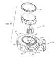
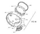
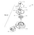
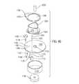
図45〜図48に見られる本発明のアセンブリ100の清浄モジュール602は、シェル660が取り外し可能に取り付けられた基部604を含む。基部604およびシェル660は一体として、清浄モジュール602のハウジングの要部を構成する。基部604には、溝切りネジ690が回転可能に取り付けられ、シェル660に配設されている。また、切削管724が溝切りネジ690を囲んでいる。本発明の図示の態様において、切削管724は、基部604の上側面に置かれたプレート710に取り付けられている。プレート710および切削管724は、清浄モジュールに嵌合されて、基部604上で回転可能である。モジュールハウジング内では、ケージ764が溝切りネジおよび切削管724を囲んでいる。ケージ764は、アーム750の自由端に位置付けられている。アーム750は、アセンブリ基部102のアーム結合器436に対するアームの結合を容易化する特徴を有する。III. Cleaning Module The
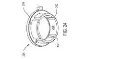
シェル660上には、キャップ680が配設されている。キャップ680は、清浄モジュール602のハウジングの一部である。キャップ680は、シェル660の上方に捕捉空間682を規定する。捕捉空間682は、ボーンストックから清浄化された軟部組織を受容するモジュールハウジングの内部の空間である。捕捉空間682には、ハブ850が配設されている。ハブ850は、溝切りネジ680および切削管724を安定させる。 A
図49および図50に見られるように、清浄モジュールの基部604は、単一のコンポーネントである。基部604には、平面プレート606を含む。プレート606は、アセンブリ基部の上部プレート122に近い形状を有する。基部プレート606の外周からは、内側リム608が下方に延びている。内側リム608の周りの下方かつ外方には、外側リム610が延びている。基部604は、清浄モジュール602がアセンブリ基部102に固定された場合に、モジュール602と一体化した外側リム610がアセンブリ基部102と一体化したリム116に対して固定されるように形成されている。 As seen in FIGS. 49 and 50, the
清浄モジュールの基部604は、基部の外側リム610を通って4つのスロット612(2つのスロットを識別)が延びるようにさらに形成されている。スロット612は、清浄モジュール602がアセンブリ基部102に固定された場合に、アセンブリ基部のラッチアセンブリ540と一体化した各タブ546がスロットのうちの別個の1つに対して位置決めされるとともに固定可能となるように位置決め・成形されている。基部604は、スロット614が内側リム608を通って延びるようにさらに形成されている。スロット614は、リム608の湾曲端部のうちの1つの部分を通って延びている。スロット614は、プレート606に短い距離だけ延入している。また、基部604には、プレート606に空間を形成する切り欠き615が形成されている。切り欠き615は、スロット614の反対のプレート606の部分から内方に延びている。 The
モジュール基部604は、2つの開口622および630を有するようにさらに形成されている。開口622は、モジュール602がアセンブリ基部102に固定された場合に、主結合器194および管結合器348上に配設されるように位置決めされている。基部604は、プレート606の上面において、開口622の周りに円形状の凹面623の中心があって、開口622の円周方向に延びるようにさらに形成されている。モジュール基部604は、開口622の周りでプレート606の下面から下方に延びた外側リング624を有するように形成されている。外側リング624の下側面からは、内側リング626が下方に延びている。外側リング624および内側リング626は、同じ直径を有しており、開口622の直径である。内側リング626の外径は、外側リング624の外径よりも小さい。モジュール基部604は、モジュール602がアセンブリ基部102に固定された場合に、内側リングの露出円形面が開口124の周りで上部プレート122の表面に対して配設されるようにさらに形成されている。基部604は、外側リング622の半径方向のすぐ外方に位置付けられた外側リング624の円形面から内方に延びた多くのボア628(1つのボアを識別)を有するようにさらに形成されている。 The
モジュール602がアセンブリ基部に固定された場合に、上部プレート122に形成された開口126に対して位置決めされるように、プレート606に開口630が形成されている。基部604は、プレート606の上面の上方に短い距離だけ延びたアイランド631を有するようにさらに形成されている。基部604は、アイランド631が開口630を囲むように成形されている。 An
モジュール基部604は、2つのロックストッパ632および638がプレート606の下面から下方に突出するようにさらに形成されている。ストッパ632および638は、開口622の中心から共通の半径方向距離だけ離れて位置付けられている。ストッパ632および638は、約90°だけ互いに弓状に離隔している。ストッパ632および636に隣接して、小さなリブがプレート606の下面から下方に突出している。リブ634は、ストッパ632に隣接して位置付けられている。リブ636は、ストッパ638に隣接して位置付けられている。リブ634および636は、ストッパ632および638が周囲に位置付けられた開口622の周りの同じ円上に存在する。リブ634および636は、ストッパ632および638の下方延伸と同じ程度にまではプレート606の下面から下方に延びていない。基部604は、リブ634および636に沿った長手方向軸に垂直な平面においてリブが凸形状を有するようにさらに形成されている。 The
図47および図48において最もよく見られるモジュールシェル650は、外壁652を有するように形成されている。外壁652は、基部604の内側リム608と外側リム610との間の外側段部に載るように成形されている。外壁652は、基部の周りに延びて、基部の全周の約70%にわたって延びるようにさらに成形されている。より詳細に、外壁652は、開口622に最も近い基部の湾曲端に対してはいない。外壁652がモジュール基部604の段部表面に対していない場合、シェル650は、内壁656を有するように成形される。シェル650は、内壁656が外壁652から半径方向内方に位置付けられるように成形されている。シェル650は、内壁656の上部に隣接して、内方に延びた溝655が存在するようにさらに形成されている。溝655は、壁656の左右長さ方向に沿って延びている。外壁652の両端から外壁652の隣接端部までは、端部パネル654が内方に延びている。シェル650は、内壁656が外壁652の全長にわたって延びないようにさらに形成されている。壁652および656の上部は大略同じ平面に存在するが、内壁656は、内壁656の下方延伸の約1/3の距離だけ下方に延びている。 The most
また、シェル650は、2つのタブ653を有しており、図48においては1つのタブを識別している。タブ653は、外壁652の底部から内方に延びている。タブ653は、壁652の両端に隣接して位置付けられている。シェル650が基部604に固定されると、1つのタブ653がスロット614の下側に位置付けられる。対向するタブ653は、切り欠き615の下側に位置付けられる。 The
外壁652の両端間には、3つのウェブ658、660、および666が延びている。ウェブ658は、大略垂直方向に整列されており、内壁656の外方に位置付けられている。ウェブ658は、端部パネル654の一方から対向する端部パネル654まで湾曲している。ウェブ658の底縁部は、外壁652の底縁部の上方に位置付けられている。ウェブ658の上縁部は、内壁656の上縁部の下側に位置付けられている。 Three
ウェブ660は、ウェブ658の上部から上方かつ内方に延びている。ウェブ666は、ウェブ660から内方かつ上方に延びている。シェル650は、ウェブ660に最も近いウェブ666の部分であるウェブ666の外周がウェブ660の内周の下側で階段状になるように形成される。ウェブ666は、内壁656の底部まで延びている。ウェブ658、660、および666は弓状であり、外壁652の端部間の隙間に対する。シェル650は、2つのリブ661および662が上方に突出してウェブ660の幅だけ延びるようにさらに形成されている。リブ661は、シェルの端部パネル654の第1の端部パネルから短い距離だけ離れて位置付けられている。リブ662は、対向するシェルの端部パネル654から短い距離に位置付けられている。リブ661および662はそれぞれ、ウェブ660の外周からウェブ660の内周まで延びている。 The
清浄モジュールのシェル650は、蓋670を具備する。蓋670は、シェルの外壁652および内壁656の上方に位置付けられている。蓋670には、開口672が形成されている。蓋670の下面からは、ボス676が下方に延びている。シェル650は、モジュール基部604に配設された場合、シェル開口672の中心が基部開口622上となり、ボス676の中心が基部開口630上となるように形成されている。蓋670の上面からは、3つのボス673(1つのボスを識別)が上方に延びている。ボス673は、シェル開口672の中心周りに中心があり、開口の外周から半径方向に離隔している。ボス673は、円周方向に等間隔で互いに離隔している。 The
また、キャップ680は、清浄モジュール602のハウジングの一部を構成している。キャップ680は、蓋670上に配設されている。キャップ680を蓋670に固定する手段は、本発明の一部ではない。このため、蓋670は、キャップ680により規定された捕捉空間682の基部を構成している。蓋670の開口672は、捕捉空間682へと開放されている。 Further, the
キャップ680の上部の周りには、エラストマ材料で形成されたリング681が延びている。リング682は、シェル650およびキャップ680を一体ユニットとして把持するのを容易化するためのものである。 A
図51に見られる溝切りネジ690は、基部プレート606に対して回転可能に取り付けられている。ネジ690は、円筒状の軸692を含む。軸の底部から上方約1/5から始まる位置では、溝694(1つの溝を識別)が軸692の周りに螺旋状に延びている。溝694は、軸692の上部まで延びている。各溝694は、刃先696(1つの刃先を識別)を規定するように形成されている。軸692の基部から上方に延びることにより、ネジ690は、図51に見られる有底ボア698を有するように形成されている。ボア698は、主結合器194と一体化したピン198を受容するように寸法規定されている。溝切りネジ690は、軸692の基部から上方に延びた円周方向に等間隔で離隔する3つの切り欠き702(1つの切り欠きを識別)を有するようにさらに形成されている。各切り欠き702は、軸692の外周からボア698まで延びている。切り欠き702は、ボア698と同じだけ軸692の上方までは延びていない。切り欠き702は、共通の幅を有する。各切り欠き702は、主結合器194と一体化した歯202が当該切り欠きに固定され得るように、十分広い。溝切りネジ690は、図46に見られる有底ボア704が軸692の上部から下方に延びるようにさらに形成されている。ボア698および704は、軸692の長手方向軸と同軸である。 The grooving
モジュールプレート606には、図46および図51に見られる回転プレート710(転動プレート710として識別される場合もある)が固定されている。転動プレート710の上面は、本質的に平面状である。転動プレート710の下面からは、ボス712が下方に延びている。ボス712は、モジュール基部604に形成された開口622での固定および回転が可能な直径を有する。ボス712の底部からボスを通ってプレート710の上面までは、ボア714が上方に延びている。ボス712の下端では、カウンターボア716がボア714の周りで半径方向外方に延びている。カウンターボア716の直径は、管結合器348の直径よりも約2mm小さい。プレート710は、円周方向に等間隔で離隔した3つの切り欠き718を有するようにさらに形成されている。切り欠き718は、カウンターボア716の外周から半径方向外方に延びている。各切り欠き718は、管結合器348と一体化した歯353の別個の1つを受容することができる。 A rotating plate 710 (sometimes identified as a rolling plate 710) as seen in FIGS. 46 and 51 is fixed to the
また、プレート710の下面からは、リング720が下方に突出している。リング720は、ボス712と同軸であり、ボス712から半径方向外方に離隔している。リング720の外径は、モジュール基部604の内部の開口622を囲む凹面623の外周の直径よりもわずかに小さい。清浄モジュール602が組み立てられた場合は、プレート710がプレート606に固定されるため、ボス712が開口622において回転可能である。リング720は、凹面623からプレート604の外周部への遷移を規定する段部のすぐ内側に位置付けられている。このため、リング720は、清浄モジュール602における転動プレート710の横方向のぐらつきを最小限に抑える。 Further, the
図46において最もよく見られる切削管724は、プレート710の内部のボア714から上方に延びている。管724は、窓728を有するようにさらに成形されている。窓728は、管を通って軸方向に延びた管腔に延入しており、管724の長手方向軸周りで互いに正反対である。窓728は、管724に形成され、弓状に離隔するとともに長手方向に延びた2つの刃先726(1つの刃先を識別)により規定されている。各刃先726は、管の内壁と、管の外壁から内方に延びて関連する窓728の側周を規定する側面との交差によって規定された縁部である。総じて、清浄モジュール602を構成するコンポーネントは、ネジ溝694の縁部696と管724に形成された刃先726との間に0.03〜0.5mmの間隙が存在するように成形されている。 The most
切削管724は、転動プレート710の内部のボア714に圧入して取り付けられている。切削管724は、窓728の下端がプレート710の上面と本質的に同一平面となるように、プレートに取り付けられている。 The cutting
図52〜図55において最もよく見られるアーム750およびケージ764は、単一のユニットとして形成されている。アーム750は、細長バーの形態である。アーム750の一端は、丸みを帯びている。アーム750の上部には、空洞752が成型されている。空洞752は、モジュール602により清浄可能なボーンストックの最大寸法を視覚的に表す標準ガイドとして用いられる。 The
アーム750は、その丸みを帯びた端部の内方に、当該アームの底部からアクセス可能な第1および第2のボア754および756が存在するように形成されている。ボア754は、円形であり、アーム750の下面から上方に延びている。ボア754は、ボア756へと開放されている。ボア756は、その長手方向軸に平行な断面において、大略頂点が丸みを帯びた三角形状である。ボア756は、断面において、ボア754の断面積よりも小さな面積に対する。ボア754とボア756間のアームの段部については、識別していない。ボア756は、有底である。ボア756の閉端の上部からは、図53においてのみ透けて見える円筒状の有底ボア757が上方に延びている。 The
アーム750は、その上面から内方に延びた窪み758(図54において識別)を有するようにさらに形成されている。窪み758は、凹状である。窪み758は、ボア754と同心でアームに形成されている。アーム750は、シェル650が基部604上に嵌合された場合に、シェルのボス676が窪み758に固定されるように形成されている。また、アーム750の下面から上方に延びた空間759を示している。空間759は、ボア754および756とは別個である。空間759は、製造上の理由のみで存在している。 The
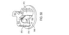
ケージ764は、大略頂点が丸みを帯びた三角形として形成された構造体である。ケージ764は、アーム750の湾曲端の反対側の端部から外方に延びている。アーム750およびケージ764は、アームの長手方向軸に略平行な線に沿って、ケージ764の相対的に短いパネル766が延びるように形成されている。ケージの長さが中間のパネル768は、短いパネルから大略垂直に延びるとともに、アーム750に隣接している。ケージの最も長いパネル770は、本質的に、ケージにより形成された三角形の斜辺であるが、パネル766および768の自由端間で延びている。ケージパネル770は、アーム750から離隔している。
ケージ764は、パネル766〜770の表面から内方に、ケージの内部の空隙765へと延入する構造的特徴を有するように形成されている。これら構造の1つは、パネル770の窪み769である。窪み769は、パネル768および770間の湾曲頂点に隣接して位置付けられている。窪み769は、空隙765へと延入するように見える。 The
空隙765へと延入する第2の構造的特徴は、押圧ブロック772である。押圧ブロック772は、パネル768の一部と、パネル768およびパネル770間のケージの部分を構成する隣接湾曲頂点の部分とから成る。押圧ブロック772は、パネル768および隣接湾曲頂点の内面の内方に位置付けられた面を有する。ケージ764は、押圧ブロック772がパネルの底縁部から上方に延びるように形成されている。押圧ブロック772は、ケージの上下距離の約半分の距離だけ上方に延びている。押圧ブロック772は、ケージにより規定された空隙に湾曲面を与える。より詳細に、押圧ブロック772は、当該押圧ブロックに沿った上下長手方向軸に垂直な平面において、当該面が凹状の曲率を有するように湾曲している。 A second structural feature that extends into the
空隙765へと延入するケージ764の第3の構造的特徴は、パネル768の内面から内方に延びたリブ776である。リブ776は、パネル766に沿った上下軸に垂直な平面において、三角形状を有する。リブ776に沿った先端線は、パネル766から最も遠く離隔したリブの部分である。リブ776は、単にパネル768の底部から垂直上方に延びた長手方向軸を有していない。代わりに、パネルの底部では、アーム750が対する領域にリブ776の基部が位置付けられている。パネル768のこの部分から上方に延びることにより、リブ776は、ケージパネル768および770間で湾曲頂点に向かって斜めに延びている。このため、リブ776の上部は、アーム750から離隔したパネル768の部分と一体化している。 A third structural feature of the
空間765へと延入するケージ764の第4の構造部材は、リブ780である。リブ780は、パネル766および770間で、パネル766の内面および湾曲頂点から内方に延びている。ケージ764に沿って垂直方向上下に延びた平面において、リブ780は、大略三角形の断面形状を有する。ケージ764は、その底部に平行ではない線に沿ってリブ780の先端が延びるようにさらに形成されている。代わりに、ケージは、パネル766の上下間の中央部の大略近傍位置から、パネル766から外方に延びたリブ780の端部が外方に延びるように形成されている。リブは、パネル768から離れる方向に延び、パネル770に至る頂点周りで湾曲している場合、上方に延びている。このため、リブ780の第2の端部は、ケージの上縁で終端するが、ここでは、パネル768および770間の頂点が湾曲してパネル770に入る。リブ780は、その先端の下側に表面782を有する。表面782は、パネル766ならびにパネル766および770間の頂点の両者から上方にテーパ状となっている。頂点771が湾曲してパネル770から離れる位置を始点として、表面782は、頂点周りかつ頂点周りに沿って下方に湾曲している。表面782は、頂点からパネル766に沿って延びる場合、下方に延びている。 A fourth structural member of the
アーム750の外側と、アームから離れる方向に突出したケージパネル768の外面との間には、ウェブ790が延びている。ケージ764の上部からは、タブ792が外方に延びている。より詳細に、タブ792は、頂点769の上部から外方に突出している。タブ792には、ケージ764から離れる方向を指す矢印形状のアイコン794が形成されている。 A
図56および図57において最もよく見られる駆動ピン802がアーム750に取り付けられるとともに、アーム750から外方に延びている。駆動ピン802は、円筒状の軸804を含む。軸804は、アーム750に形成されたボア754に固定されるように寸法規定されている。軸804は、アセンブリ基部102の一部であるアーム結合器486のヘッド490の直径と略等しい直径を有する。ピン802の軸804からは、ヘッド806が上方に延びている。ヘッド806は、三角形状であり、軸804により規定された円内の断面領域に対する。ピンのヘッド806は、アーム750に形成されたボア756にしっかりと嵌合するように寸法規定されている。 The drive pins 802, most commonly found in FIGS. 56 and 57, are attached to the
駆動ピン802は、ヘッド806が延びる端部の反対側の軸端部である軸804の基部において、2つの先端部808が軸から離れる方向に延びるようにさらに形成されている。先端部808は、共通の平面に存在する。先端部808は、互いに弓状に離隔している。駆動ピン802は、本質的にピン軸804の外面を構成する湾曲壁から離れるように接線方向に延びた外側面を各先端部808が有するように成形されている。 The
駆動ピン802は、軸804の基部から上方に延びたスロット810を有するようにさらに形成されている。スロット810は、矩形状であり、アセンブリ基部のアーム結合器586と一体化したバー492を受容するように寸法規定されている。本発明の図示の態様において、スロット810は、半径方向に軸804をわずかに越えて、先端部808間のウェブ中に突出している。スロット810の天井を規定する軸804の内面からは、ボア812が上方に延びている。ボア812は、軸804およびヘッド806を通って延びている。 The
清浄モジュール602の組み立てに際して、アーム750は、ボア754および756がモジュール基部604の開口630上に位置付けられるように位置決めされる。アーム750の位置決めの結果として、ケージ770は、プレート710上に配設されて、溝切りネジ690および外周管724を囲む。駆動ピンの軸804は、アームに形成されたボア754および756それぞれに軸およびヘッドが固定されるように、開口630に挿入されている。ピンのボア812およびアーム750の内部のボア757を通って延びた締結具814(図46においてのみ見られる)がピン802をアーム750に保持する。駆動ピンと一体化した先端部808およびスロット810は、アーム750を支える表面と反対側のプレート表面であるプレート604の下面に隣接して位置付けられている。 Upon assembly of the
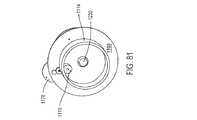
ここで図60および図61を参照して説明するロックディスク818がモジュール基部604に回転可能に取り付けられて、プレート604の下面の下側に位置付けられる。ロックディスクは、円形プレート820を含む。プレート820の上面には、2つのタブ822が配設されている。タブ822は、プレートの中心に対して、互いに正反対である。各タブ822は、プレート820の上面から上方に延びている。プレート上面の上方に配設されたタブ822の部分は、プレート820の境界を越えて半径方向外方に突出している。また、プレート820の上面からは、リッジ824が上方に延びている。リッジ824は、3つの部分からなる構造体であるが、個々の部分は識別していない。プレート820の境界に隣接して、中央部が位置付けられている。この中央部は、湾曲形状であり、約20〜30°の円弧に対する。中央部の両端からは、2つの端部が半径方向外方に突出している。端部は、プレートの境界を越えて、約5mmの短い距離だけ突出している。このため、リッジ824は、プレート820の外周に隣接して位置付けられたほぞ826を規定している。 The
ロックディスク818は、孔826を通って位置付けられた中心を有するようにさらに形成されている。ロックディスク818は、モジュール基部604の外側リング624を固定し得るとともにディスク818がリング624周りに回転し得る直径を孔826が有するように形成されている。プレート820と一体的に形成された環体828がプレートの上面から上方に延びるとともに、孔826の周りに延びている。環体828は、孔826の中心から異なる距離に位置付けられた外側面を有するように形成されている。縁部を識別している第1の側面829は、孔826の中心から最も遠くに位置付けられた弓状面である。環体828は、その境界周りで180°よりも大きく伸びた円弧に表面829が対するように形成されている。一端において、表面829は、湾曲して表面830に入る。表面830は、孔826の周りの大略直線状の経路に沿っている。表面830は、弓状の表面832と1つになる。表面832は、孔826の中心周りに中心がある。表面829に対して、表面832は、孔826の近くに位置付けられている。表面832から離れる方向には、線形面834が弓状かつ半径方向外方に延びている。また、表面834が隣接線形面836まで延びている。表面836は、表面832上に存在することになる接線に略平行な線に沿って位置付けられており、そこで表面832および834が会合する。また、表面838が表面829まで延びている。 The
ロックリング818は、タブ839が環体828の表面828から半径方向外方に延びるようにさらに形成されている。タブ839には、窪み840が形成されている。窪み840は、モジュール基部604から下方に延びたリブ634または636のいずれか一方を受容するように寸法規定されている。 The
ロックディスク818の下面からは、リング842が下方に延びている。リング842は、孔826の外周方向に延びている。また、プレート824の下面からは、リム844が下方に延びている。リム844は、ディスク818の外周から下方に延びている。リム844は、プレート824の外周の円周方向に完全に延びているわけではない。プレートは、リムの無い約30〜50°の円弧に対する部分を有する。リム844の一端は、斜面846を有するように形成されている。表面846は、弓状に延びるため、プレート824の表面からリム844の最底面へと離れるようにテーパ状となっている。 A
ロックリング818は、リング842の下側面から上方に延びた有底ボア847を有するようにさらに形成されている。ボア847は、リッジ824の上方のリングの部分に位置付けられている。ボア847には、磁石848が配設されている。 The
清浄モジュール602は、基部604の下面に隣接してロックディスク818を位置決めすることにより組み立てられ、外側リング624が孔826に固定されるとともに、ディスクを越えて短い距離だけ下方に延びる。このロックディスクの位置決めの結果として、駆動ピン802と一体化した先端部808は、環体828に隣接してディスクの表面に配設される。モジュール基部604と一体化したリング624および626間の段部表面に対して、保持用リング849が固定される。リング849の孔および基部のボア628を通って、締結具851(図72において1つを識別)が延びており、リングを基部に保持している。リング849の外径は、ロックディスク818の内部の孔826の直径よりも大きい。このため、リング846は、モジュール基部604と一体化したリング842の下に突出する。リング849は、このようにしてロックディスクをモジュール基部604に保持する。清浄モジュールが組み立てられた場合、ロックディスク818は、プレート606の下面の下側に離隔している。プレート606とディスク818との間の空間には、タブ822およびほぞ826が配設されている。ほぞ826は、モジュール基部604と一体化したリング608におけるアクセス可能な貫通スロット614である。 The
清浄モジュール602の内部の捕捉空間682には、図58および図59において最もよく見られるハブ860が配設されている。ハブ860は、単一のコンポーネントである。ハブ860は、ディスク状の基部862を有する。基部862には、その対向する下側面と上側面との間に延びた中心開口864が形成されている。基部862の下側面は、その下層のシェルの蓋670に対向する表面であることが了解される。また、基部862の対向する下側面と上側面との間には、互いに開口864の半径方向外方に離隔するとともに円周方向に等間隔で離隔した3つのボア868(1つのボアを識別)が延びている。各ボア868は、カウンターボアを有する(カウンターボアは識別せず)。ハブ860は、その中心開口864がシェルの蓋670の開口672上に配設されるように基部862が位置決めされた場合に、ボア868と関連付けられたカウンターボアのうちの別個の1つにおいて、蓋670に形成されたボス673のそれぞれが固定されるように成形されている。蓋のボスおよびハブのボア868を通って延びた締結具は、ハブをシェルの蓋670の上部に保持するが、締結具は図示していない。 The
基部862の外面からは、同じくハブ860の一部である円周方向に等間隔で離隔した3つの支柱870(2つの支柱を識別)が上方に延びている。支柱870は、中心開口864の境界に隣接して位置付けられた円上に位置付けられている。各支柱870の上部からは、ウェブ872が半径方向内方に延びている。ウェブ872は、中心開口864の中心の上方位置で会合する。ウェブ872の会合位置からは、ピン874が下方に延びている。ピン878の自由端の下側には、足部878が延びている。足部878の直径は、ピン874の直径よりも小さい。より詳細に、ピンの足部878は、溝切りネジに形成されたボア704に密に滑合し得る直径を有する。清浄モジュール602が組み立てられた場合は、ピンの足部878が溝切りネジ690に固定され、ネジがピン874周りに回転可能である。 From the outer surface of the
シェル650には、図47および図48において最もよく見られるラッチ880が移動可能に取り付けられている。ラッチ880には多くのパネルが形成されており、ラッチを構成するパネルがシェル内壁656ならびにウェブ658、660、および666に隣接して位置付けられるようになっている。パネルのうちの1つからは、2つの弓状ビーム882が下方に延びている。最上部のウェブからは、弓状のリップ部884が外方に突出している。清浄モジュール602を構成するコンポーネントは、ラッチ880がシェルにスナップ嵌合して、ビーム882がシェルのウェブ666上に固定されるとともに、リップ部884がシェルの溝655に固定されるように形成されている。ラッチ880は、シェル内壁656ならびに隣接ウェブ658、660、および666が対する円弧よりも小さな円弧に対する。このため、ラッチ880は、シェル内壁656ならびに隣接ウェブ658、660、および666上を摺動可能である。 The
ラッチ880の最下パネルは、シェルのウェブ658の下側に延びている。ラッチの最下パネルの底縁部から離れる方向には、タブ886が垂直に突出している。このため、タブ886は、シェルのウェブ658の底縁部の下側で内方に延びている。ラッチは、ロックディスク818に規定されたほぞ826にタブ886が固定され得るように成形されている。 The bottom panel of the
IV.粉砕モジュール
図62に見られる粉砕モジュール902は、一体的に当該モジュールのハウジングを構成する底部シェル904および上部シェル940を含む。上部シェル940は、底部シェル902の上方に配設されている。シェル902および940間には、切断ディスク958および衝突プレート984が配設されている。上部シェル940からは、ホッパー952が上方に延びている。ホッパー952を通して、プランジャ953を押すことができる。切断ディスク958の下側では、底部シェル904に対して捕捉トレイ980が取り外し可能に取り付けられている。IV. Grinding Module The
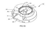
図63および図64に見られるように、清浄モジュールと一体化した底部シェル904は、リム906を有する。リム906は、アセンブリ基部102の上部の周りに延びた段部115に固定されるように寸法規定されている。リム906は、4つの開口908を有するように形成されており、1つの開口を識別している。シェル904は、清浄モジュール902がアセンブリ基部102に固定された場合に、ラッチアセンブリのタブ548が開口908に固定されて、モジュール902を解放可能に基部102に保持し得るように形成されている。 As seen in FIGS. 63 and 64, the
底部シェル904は、平面状の上面910を有するようにさらに形成されている。上面910の下側には、大略円形状の凹面912が位置付けられている。上面910からは、複数のボア913(1つのボアを識別)が内方に延びている。ボア913は、凹面912の周りに位置付けられ、半径方向外方に離隔している。シェル904は、凹面912に2つの開口が存在するように形成されている。第1の開口914は、円形状であり、凹面912の中心と同心である。第2の開口918は、凹面912の外周から内方に延びている。開口918は、開口914に向かって延びている。凹面912からは、リング916が上方に延びており、円周方向に開口914を囲んでいる。リング916は、開口914と開口918間の障壁として機能する。シェル904は、同じく凹面912から上方に延びた第2のリング920を有する。リング920は、凹面912の外周のすぐ内方に位置付けられている。リング920は、凹面912の円周方向には延びていない。代わりに、開口918がリング920を遮断する。 The
底部シェル904は、リム906から上面910まで上方に延びた多くのパネルを有するようにさらに形成されている(パネルは識別していない)。側部パネルのうちの1つには、開口924が形成されている。開口924は、シェルへと内方に延入しており、開口918の下側に位置付けられるとともに開口918に連続するように位置決めされている。また、底部シェル904は、上面910を構成するシェルのパネルが切り欠き911を有するように成形されるように成形されている。切り欠き911は、開口924を規定する上面規定パネルの部分から内方に延びている。 The
シェルの凹面912の下面からは、スリーブ926が下方に延びている。スリーブ926は、開口914から下方に延びた貫通ボア928を規定している。底部シェル904は、多くのウェブ930が上面の下面から下方に延びるとともに、シェルの側部を構成するパネルから内方に延びるようにさらに形成されている。ウェブ930は、底部シェルに構造的形状を与える。ウェブ930のうちの1つは、上方に延びた開口932を規定する。底部シェル904は、粉砕モジュール902がアセンブリ基部102に載置された場合に、ボア928の中心が主結合器194上となり、開口932の中心がアーム結合器486上となるように成形されている。 A
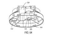
ここで図65および図66を参照して説明する上部シェル940は、粉砕モジュール902と一体化しており、平面状の基部942を有する。シェルの基部942は、底部シェル904の上面910上に固定されるように寸法規定されている。上部シェル940は、基部942の平面状の底面の上方に位置付けられた円形状の隆起面944を有するように形成されている。基部942を規定するシェル940の部分を通って、一組の開口943が上下に延びている。開口943は、隆起面944の周りで半径方向外方に位置付けられている。粉砕モジュール902は、底部シェルの凹面912と一体化した凹面と同心で同じ直径となるように隆起面944が位置決めされるように形成されている。各開口943は、底部シェルのボア913の上方に中心がある。締結具941(図65においては1つが見られる)が上部シェルの各開口943を通って、下層の底部シェルのボア913に延入している。締結具941は、このようにして上部シェル940を底部シェル904に保持する。 The
基部942からは、隆起面944と同心の2つのリングが下方に延びている。表面942からは、その中心に隣接して、内側リング945が下方に延びている。隆起面からは、外側リング946が下方に延びて、隆起面の外周のわずか内方に位置付けられている。より詳細に、粉砕モジュール902が組み立てられた場合、リング945は、底部シェル904と一体化したリング916上に配設される。外側リング946は、下層のリング920上に配設されている。 From the
シェルの基部942は、切り欠き943を有するようにさらに形成されている。切り欠き943は、長円形状である。切り欠き943は、モジュール902の組み立てに際して、底部シェルの上面910に形成された切り欠き911の直上に位置付けられるように位置決めされている。切り欠き943は、基部942を完全に通って延びているわけではない。 The
上部シェル940の基部942は、開口948を有するようにさらに形成されている。開口948は、リング944および946間の隆起面944の部分へと開放されている。より詳細に、上部シェルの開口948は、底部シェルの開口918上となるように位置決めされている。上部シェル940は、ホッパー952が開口948の周りでシェルの基部942から上方に延びるようにさらに形成されている。また、上部シェル940の基部942は、図66において縁部を識別している空洞950を有するように形成されている。空洞950は、隆起面944から上方に延びている。上部シェル940は、空洞950が開口948に隣接して連続するように形成されている。 The
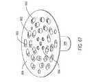
図67において最もよく見られる切断ディスク958は、円形状であり、底部シェルの凹面912と上部シェルの隆起面944との間の空間に置かれるように寸法規定されている。より詳細に、切断ディスク958は、凹面912の上方に延びたリング916および920に置かれている。切断ディスクの直径は、ディスクが固定される空隙の直径よりも約4mm小さい。切断ディスク958の厚さは、底部シェルのリング916および920を上部シェルのリング945および946から分離する距離よりも約0.25mm小さい。このため、切断ディスク958は、ディスクが固定される空隙中の回転のほか、限られた量の側方移動および限られた量の上下移動が可能である。 The most commonly seen cutting
切断ディスク958には、複数の切断要素960が形成されており、1つの要素を識別している。切断要素960の厳密な構造は、本発明の一部ではない。切断要素のこのような構造としては、米国特許出願公開第US2009/0118735号/PCT出願公開WO2009/061728号に開示されたものがあり、これらを援用する。一般的には、各切断要素が刃先962(1つの刃先を識別)を有することが了解されるものとする。各刃先962は、切断ディスク958の開口963の一部を規定しており、1つの開口を識別している。切断ディスクは、円周方向に等間隔で離隔した4つの開口964(1つの開口を識別)を有するようにさらに形成されている。開口964は、切断要素960の半径方向内方に位置付けられている。 A plurality of cutting
切断ディスク958の中心からは、図68および図69において最もよく見られるシャフト966が下方に延びている。シャフト966は、形状が大略円筒状である。シャフトは、ヘッド970を有するように形成されている。シャフトヘッド970は、底部シェル904の内部のボア928で固定および回転可能な直径を有する。ヘッド970の下側には、円筒状の軸972が延びている。軸972の直径は、ヘッド970の直径よりも小さい。シャフトは、軸972の底部から上方に延びた有底ボア974を有するように形成されている。ボア974は、シャフト966の長手方向軸上に中心がある。ボア974は、主結合器194と一体化したピン198を受容するように寸法規定されている。シャフト966は、ボア972の基部から半径方向外方に延びた円周方向に等間隔で離隔する3つの切り欠き976を有するようにさらに形成されている。切り欠き976は、ボア974と同じだけシャフトの軸972へと上方までは延入していない。切り欠き976は、主結合器194と一体化した歯202を受容するように寸法規定されている。 A
シャフトヘッド970の上面からは、4つのピン980(1つのピンを識別)が上方に延びている。ピン980は、切断ディスク958の内部の開口964を通ってその上に延びている。このため、ピン980は、シャフト966を切断ディスク958に保持する。粉砕モジュール902が組み立てられた場合、シャフト966は、底部シェル904の内部のボア928に配設される。 Four pins 980 (identifying one pin) extend upward from the upper surface of the
図62に見られる衝突プレート984は、上部シェル940に形成された空洞950中に取り付けられている。衝突プレート984は、開口948の直下の表面を有するように形成されている。粉砕モジュール902は、モジュールの作動時に、切断ディスクの刃先962が衝突プレート984の被覆面に向かって回転するように設計されている。 The
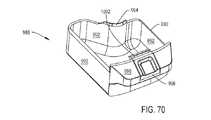
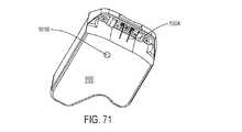
ここで図70および図71を参照して説明する捕捉トレイ988は、底部シェル904の内部の開口924において摺動可能に固定されるように寸法規定されている。捕捉トレイ988は、一組のパネル992(3つのパネルを識別)が上方に延びる基部990を有する。シェルスリーブ926の最も近くに位置付けられたパネルである最も内側のパネル992からは、リップ部994が上方に延びている。捕捉トレイ988は、粉砕モジュール902のその他の部分から取り外された場合に、開口918の直上に位置付けられた切断ディスク958の部分の下側でリップ部が掃集を行うように形成されている。 The
また、リップ部994が延びるパネルから最も遠くに離隔したパネルである最も外側のパネル992からは、取っ手996が外方に突出している。取っ手996は、リップ部が関連付けられたパネルの前方に延びている。取っ手996は、粉砕モジュール902のその他の部分に対するトレイの挿入および取り外しのためにユーザが把持する捕捉トレイの部分として機能する。 Further, the
取っ手996には、ラッチ998が枢動可能に取り付けられている。ラッチ998には、捕捉トレイ988のその他の部分の上方に突出したタブ1002を含む。タブ1002は、捕捉トレイが開口924に完全に固定された場合に、上部シェル940の内部の切り欠き943に固定されるように位置決めされている。バネ1004(1つのバネを識別)は、タブ1002が切り欠き943に配設される状態であるロック状態においてラッチを垂直に保持する力をラッチに加える。ラッチ998の本体に加わる指の力は、ラッチ998の枢動のためにバネ1004が加える力に打ち勝つのに十分である。ラッチ998の枢動により、切り欠き943の外側でタブ1002が回転する。タブ1002がこのように回転したら、清浄モジュール902のその他の部分から捕捉トレイ988を取り外すことができる。 A
捕捉トレイ988の基部990には、磁石1010が取り付けられている。磁石1010が固定された基部990のボアについては、識別していない。本発明のアセンブリ100を構成するコンポーネントは、捕捉トレイ988が清浄モジュール902に係止されるとともに清浄モジュールがアセンブリ基部102に固定された場合に、磁石1010がセンサ587の上方に位置付けられるように配置されている。 A
V.動作
本発明のアセンブリ100の使用準備の第1のステップは、電源595および/またはモータコントローラ596を含むコンソールのアセンブリ基部102への接続である。このステップは、これらのサブアセンブリがアセンブリ基部102と別個である場合に必要である。その後、アセンブリ基部の上部プレート122上に清浄モジュール602を固定する。より詳細には、ラッチアセンブリ540の一部であるタブ548が清浄モジュールのスロット612を通って延びるように、清浄モジュール602をアセンブリ基部に嵌合する。バネ566は、ラッチプレート542および544ひいてはラッチプレート546に十分な力を加えることで、タブ548をそれぞれの外側位置に維持する。タブ548が外側位置にある場合は、ラッチアセンブリ540が係止状態にある。V. Operation The first step in preparing the
清浄モジュール602がアセンブリ基部102に係止された場合は、図72に見られるように、溝切りネジ690の軸692が主結合器194上に配設される。結合器の歯202が被覆溝の切り欠き702に固定されていない場合は、主結合器194がバネ212に下から支えられている。プレート710と一体化したボス712の切り欠き718規定部は、管結合器348上に配設されている。管結合器348と一体化した歯353が切り欠き718に固定されていない場合、管結合器348は、バネ394を下に押し込む。駆動ピン802の軸804は、ケージ結合器486上に配設されている。駆動ピンと一体化したスロット810において、アーム結合器486と一体化したバー492が固定されていない場合、アーム結合器は、バネ504を下に押し込む。 When the
清浄対象のボーンストックをモジュール602に配置するには、シェル650を持ち上げてモジュール基部604から外す必要がある。シェル650を取り外すには、ラッチ880をアンロック状態まで回転させる。これは、図1に見られるように、ラッチ880を反時計回りに回転させることを意味する。ほぞ826に対するタブ886の係合によってラッチをこのように回転させることにより、ロックプレート818も同様に回転する。このロックプレート818の回転の結果として、ロックプレートのタブ822は、回転によってシェル650と一体化したタブ653から外れる。これにより、シェルを基部604から取り外すことができる。 In order to place the bonestock to be cleaned on the
ロックプレート818の回転の別の結果として、センサ586から離れる方向に磁石848が回転する。本発明の多くの態様において、モータコントローラ596は、センサ586または587の一方からの信号がセンサのごく近くの磁石の存在を示している場合、モータ140を作動させ得るように構成されている。ロックプレート818がアンロック位置にある場合は、センサ586にもセンサ587にも磁石は隣接していない。これは、スイッチ588または590を押下してもモータ140が作動しないことを意味する。 As another result of the rotation of the
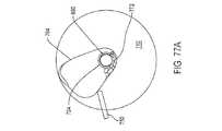
また、ロックプレート818の回転の結果として、ロックプレートと一体化した環体828も回転するため、駆動ピン802の先端部808の両者ではないにせよ、一方に対して環体の表面829が回転する。先端部808の回転によって、駆動ピン802も同様に回転し、ひいてはアーム750およびケージ764が枢動する。具体的に、ケージ764は、図77Dに見られる溝切りネジに対する配向となるように位置決めされている。環体の表面829に対して少なくとも1つの先端部808が隣接する結果、駆動ピン802ひいてはアーム750およびケージ764のさらなる移動が抑止される。 Further, as a result of the rotation of the
ラッチ880がアンロック位置まで回転すると、環体828と一体化したタブ839がストッパ632に隣接することによって、ラッチのさらなる回転が阻止される。ロックプレート818がこのように位置決めされると、リブ634が窪み840に固定されて、ロックプレートひいてはラッチ880を解放可能にアンロック位置に保持する。 When the
そして、清浄および粉砕対象のボーンストックをケージ764の内部の空隙765に配置する。シェル650がモジュール基部604上で後方に固定される。基部604へのシェルの固定の結果、ハブ860と一体化したピン足部878は、溝切りネジ690の内部のボア704に固定される。図1に示す位置へとラッチ880が回転すると、シェルがロック状態に戻る。このラッチの回転の結果として、ロックプレート818は、ロック状態まで回転する。ロックプレート818の回転により、ロックプレートのタブ822は、シェル604と一体化したタブ653上に固定される。このタブ上タブ位置決めによって、シェル650は、基部604に対して解放可能にロックされる。 Then, the bone stock to be cleaned and crushed is placed in the
ロックプレート818の回転の結果として、ロックプレートの環体828は、図74に見られるように、駆動ピン802と一体化した先端部808に対する配向となる。より具体的に、環体828は、先端部808から離隔する。これは、駆動ピンひいてはアーム750およびケージ764が回転しなくなることを意味する。 As a result of the rotation of the
ラッチ880がロック位置まで回転すると、環体828と一体化したタブ839がストッパ638に隣接することによって、ラッチのさらなる回転が阻止される。ロックプレート818がこのように位置決めされると、リブ636が窪み840に固定されて、ロックプレートひいてはラッチ880を解放可能にロック位置に保持する。 When the
また、ロックプレート818のロック位置への回転により、磁石848は、センサ586上で回転する。これにより、センサ586は、磁石の存在を示す信号をモータコントローラ596に出力する。モータコントローラ596は、清浄モジュール602が基部に取り付けられ、モジュールのシェル650がモジュール基部604にロックされた状態にアセンブリ100があることを示すものとして、この信号を解釈する。モータコントローラ596は、アセンブリ100がこの状態にあるものと判定した場合、スイッチ586に隣接するLED588を作動させる。これにより、アセンブリの作動のために押下すべきスイッチが清浄プロセスの開始に用いられるスイッチ586であることが視覚的に示される。 Further, the rotation of the
スイッチ586が押下されると、モータコントローラ596は、設定期間にわたってモータ140を作動させる。この期間は、3〜20分であることが多い。以下に論じる通り、モータ140の作動によって、3つの結合器194、348、および486も同様に回転移動する。主結合器194が回転すると、バネ214は、被覆溝切りネジ690の切り欠き702へと結合器の歯202を付勢する。これにより、溝切りネジ690は、主結合器194とともに回転する。バネ394が管結合器348を上方に付勢するため、結合器の歯353は、転動プレート710と関連付けられた切り欠き718に固定される。このスロット内歯係合によって、転動プレートおよび切削管は、管結合器とともに回転する。バネ504によって、回転するケージ結合器のバー492は、駆動ピン802と一体化したスロット810に固定される。このため、駆動ピンは、ケージ結合器の回転運動をアーム750およびケージ764に伝える。 When the
実際の骨清浄プロセスは、複数の清浄サイクルから成る。各サイクルは、一組のフェーズから成る。本発明のこの態様において、モータ140は、歯車列144および軸170によって、主結合器194を継続的に回転させる。主結合器194に接続された溝切りネジ690は、主結合器とともに回転する。溝切りネジ690は、その回転が骨清浄プロセスに寄与し得ない後述のフェーズのいくつかにおいてさえ回転する。 The actual bone cleaning process consists of multiple cleaning cycles. Each cycle consists of a set of phases. In this aspect of the invention, the
軸170の回転移動は、歯車列220によって、アームカム234およびクラッチカム252に伝えられる。アームカム234は、図75に示すカムを見る視点で反時計回りに回転する。クラッチカム252についても、図76に示すカムを見る視点で反時計回りに回転する。 The rotational movement of the
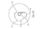
清浄サイクルの第1のフェーズは、押圧フェーズである。押圧フェーズにおいては、クラッチカム252の内側ローブ258が歯止め396に乗り上がる。図76において、歯止め396のローラ412は、三角形で表される。これは、クラッチが非係合状態であることを意味する。したがって、転動プレート710および切削管724は回転しない。同時に、アームカムの外側ローブ238は、ロッカーアーム508に対して回転する。図75において、アームカム234に支えられたロッカーアーム508のローラ524は、円で表される。結果として、ロッカーアーム508およびクランク448が協調して、シャフト422を特定の回転配向に保持する。この特定の回転配向は、図77Aにより表される配向のように、押圧ブロック772が切削管724の内部の窓728に向かうようにケージが位置決めされた配向である。 The first phase of the cleaning cycle is the pressing phase. In the pressing phase, the
前のサイクルの後述の掃集フェーズを通じて清浄モジュール602が循環した結果として、清浄対象の骨片は、押圧ブロック772に隣接するケージ空隙765に前もって収集されている。以下に論じる通り、押圧ブロック772は、切削管の窓728の比較的近くに位置付けられるように位置決めされる。溝切りネジおよび切削管に対して押圧ブロックをこのように近く位置決めする利点として、ボーンストックが溝切りネジ690に押し付けられる可能性が高くなる。これは、清浄モジュール602が押圧フェーズにある場合、押圧ブロック772が管の窓728を通じて、回転する溝切りネジ690にボーンストックを押し付けることを意味する。ボーンストックに付着した軟部組織は、回転する個々の溝694に引きずり込まれることになる。回転する溝694は、切削管724の刃先726に対して軟部組織を引っ張る。この切削管に対する組織の移動によって、組織が骨から切り取られる。より具体的には、切削管の静的な刃先に対する溝切りネジの回転する刃先696の移動によって、ボーンストックから軟部組織が切り離される。 As a result of the
清浄モジュール602が個々の押圧フェーズを循環するのに先立って、押圧ブロック772により溝切りネジ690に押し付けられる1つまたは複数のボーンストックのサイズおよび形状を把握することはできない。押圧ブロック772がさまざまなサイズおよび形状のボーンストックを溝切りネジ690に押し付けるように、ケージドライバ420のハット464がシャフト422に対してある程度回転し得ることが思い起こされる。バネ534は、シャフト422周りの特定の回転配向にてハット464を保持する。より詳細に、バネ534は、押圧ブロック772に対してボーンストックが存在しない場合、ハット464、アーム結合器486、駆動ピン802、およびアーム750が協調してケージ764を保持することにより、切削管の窓728から離れる方向に短い距離だけ押圧ブロック772が離隔するような配向にてシャフトを保持する。本発明のほとんどの態様において、清浄モジュールは、押圧ブロックに隣接してボーンストックが存在せず、清浄サイクルが押圧フェーズにある場合、押圧ブロックと切削管724の外面との間の最大距離が8mmとなるように構成されている。より理想的には、ボーンストックが存在しない場合の押圧ブロックと切削管724との間の最大距離が4mmである。 It is not possible to ascertain the size and shape of one or more bonestocks pressed against the grooving
ボーンストックが押圧ブロック772と切削管724との間に挟まれている場合、シャフト422とケージ764との間の遊びは、ケージの移動により、不変の力が溝切りネジ690に対して押圧ブロックをその近接位置へと付勢することにはならないことを意味する。代わりに、バネ534は、関連するコンポーネントがケージ764に力を加えることになるトルクをハット464に与える。この力がケージに加えられることにより、押圧ブロック772は、切削管の窓728を通じて回転する溝694へとボーンストックを押し込む。本発明のいくつかの態様において、アセンブリ基部102は、力バネ534によって、押圧ブロック772と溝切りネジ690との間に捕捉されたボーンストックに対して8〜40ニュートンの力をケージ764が加えるように構成されている。 When the bone stock is sandwiched between the
押圧フェーズにおいて、溝切りネジ690には、横乗せが生じる。ネジ690の内部のボア704に静的なピン874が存在することにより、このような横乗せによって、溝694が切削管724の内面を削り始める点へと溝切りネジ690がそれないようにする。 In the pressing phase, the grooving
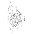
押圧フェーズの後は、転動フェーズである。アセンブリは、クラッチカム252が回転してカムの外側ローブ262が歯止め396に対して回転したことの結果として、押圧フェーズから転動フェーズに遷移する。その結果としてタブ304から離れる方向に歯止めが枢動することにより、クラッチは係合状態へと移行する。したがって、転動プレート710および切削管724は、溝切りネジ690と同時に同じ方向へ同じ速度で回転する。アームカム234の外側ローブ238は、ロッカーアーム508に対して回転し続ける。これにより、モジュールの押圧フェーズの遷移中と同様に、ケージは、切削管に対して同じ位置のままである。 After the pressing phase, there is a rolling phase. The assembly transitions from the pressing phase to the rolling phase as a result of the
切削管724は、その回転の結果として、図77Bの表示における反時計方向に、管の窓に配設されたボーンストックを回転させる。これにより、切削管724と押圧ブロック772との間の空間からボーンストックが除去される。 As a result of its rotation, the cutting
転動フェーズにおいては、転動プレート710の回転によって骨の転動を補助し得る。 In the rolling phase, the rotation of the rolling
転動フェーズの後は、移行フェーズである。移行フェーズへの遷移は、外側ローブ238と内側ローブ242との間のアームカム234の線形面がロッカーアーム508に対して回転した場合に生じる。その結果としてのロッカーアーム508の枢動により、ケージドライバ420は、図77Cに見られるように、押圧ブロック772が溝切りネジ690から離れる方向に移動し、リブ780が溝切りネジに向かって移動するようにケージ764を枢動させる。 After the rolling phase is the transition phase. The transition to the transition phase occurs when the linear plane of the
移行フェーズにおいて、クラッチカム252の外側ローブ262は、歯止め396に乗り上げ続ける。転動プレート710および切削管724は、回転し続ける。移行フェーズ中の清浄モジュールのこれらコンポーネントの回転は、骨の清浄に明確には寄与しない場合がある。 In the transition phase, the
図77Cに示すように、清浄プロセスにおいては、比較的高速に回転する溝切りネジと低速回転の切削管724との間にボーンストックが捕捉される可能性がある。この事象は、軟部組織の尾部が管の窓728に引き込まれて溝切りネジ690に巻き付けられ得るために生じる。組織は、溝694に捕捉されていない場合、組織の切断に要する力で刃先726に押し付けられない場合がある。 As shown in FIG. 77C, bone stock can be trapped between a grooving screw that rotates at a relatively high speed and a cutting
アームカム234の回転によってカムの内側ローブ242がロッカーアーム508に乗り上げると、本発明のアセンブリは、除去および捕集フェーズに入る。除去および捕集フェーズにおいて、クラッチカム252の外側ローブ226は、歯止め396に乗り上げ続ける。 When the rotation of the
したがって、除去および捕集フェーズ中、リブ780は、溝切りネジおよび切削管にごく近接している。溝切りネジ、転動プレート、および切削管は、回転し続ける。転動プレートの回転の結果として、図77Dに見られるように、ケージパネル770の内面に向かってボーンストックが回転する。このように、リブ780は、捕捉されたボーンストックの清浄アセンブリ、溝切りネジ、および切削管からの除去を容易化する清浄モジュールのコンポーネントとして機能する。 Therefore, during the removal and collection phase, the
切削管の回転の結果として、溝切りネジと切削管との間に捕捉されたボーンストックがリブ780に対して回転する。ほとんどの場合、ボーンストックは、表面782に対して回転する。ボーンストックは、表面782に沿って下方に移動する。骨が下方に移動すると、回転する切削管724の刃先726に対して組織の尾部が押し付けられる。この組織に対する刃先の動作の結果として、組織がボーンストックから切り離される。ボーンストックは、このようにして、溝切りネジ690を使わずに切断される。 As a result of the rotation of the cutting tube, the bonestock trapped between the grooving screw and the cutting tube rotates with respect to the
単一の清浄サイクルの最終フェーズは、掃集フェーズである。クラッチカム252の回転の結果として、カムの内側ローブは、歯止め396に対して回転する。その後、タブ304は、歯止め396に対して押し戻される。これにより、クラッチ278は、非係合状態に戻る。したがって、転動プレート710および切削管724は、回転を停止する。より具体的に、この事象が発生した場合、切削管724は、次の押圧フェーズにおいて押圧ブロックを窓728に向かわせられるようにする必要がある。 The final phase of a single cleaning cycle is the sweeping phase. As a result of the rotation of the
また、掃集フェーズにおいては、アームカム234の回転の結果として、内側ローブ242と外側ローブ238との間のカム遷移面がロッカーアーム508に対して回転する。このため、図77Eにより表されるように、ケージドライバ420がケージ764を枢動させるため、押圧ブロック772は再び、図77Aにより表される押圧フェーズの場合の位置に戻される。ケージ764は、この運動の結果として、パネル770に対して配設されたボーンストックを切削管の窓728に押し付ける。これにより、掃集フェーズの最後には、ボーンストックが再び押圧ブロック772によって切削管の窓に押し付けられる。 Also, in the sweeping phase, as a result of the rotation of the
掃集フェーズの完了によって、単一の清浄サイクルによる清浄モジュールのコンポーネントの移動は終了となる。その後、アセンブリは、後続の清浄サイクルの押圧フェーズへと清浄モジュールを進ませる。 Completion of the sweep phase ends the movement of the components of the cleaning module in a single cleaning cycle. The assembly then advances the cleaning module to the pressing phase of the subsequent cleaning cycle.
本発明のいくつかの態様において、単一の清浄サイクルは、3〜20秒にわたって続く。押圧フェーズは、サイクルの25〜50%にわたって続く。理想的には、単一の押圧フェーズにおいて、少なくとも6回転ではないにせよ、溝切りネジが少なくとも4回360°回転するものとする。転動フェーズは、単一の清浄サイクルの10〜40%を占める。単一の転動フェーズにおいて、切削管は、3回以上の一回転ではないにせよ、少なくとも2回の一回転を行うものとする。除去および捕集フェーズは通常、単一の清浄サイクルの5〜20%を占める。移行および掃集フェーズはそれぞれ、単一の清浄サイクルの5〜15%を占める。本発明のいくつかの態様において、アセンブリは、作動によってボーンストックを清浄したら、3〜20分の期間にわたって作動状態を維持する。アセンブリ100は、5〜20分の期間にわたって作動する場合が多い。本発明の多くの態様において、アセンブリは、8〜15分の期間にわたって作動する。 In some embodiments of the invention, a single cleaning cycle lasts from 3 to 20 seconds. The pressing phase lasts for 25-50% of the cycle. Ideally, the grooving screw should rotate 360 ° at least four times, if not at least six times, in a single pressing phase. The rolling phase occupies 10-40% of a single cleaning cycle. In a single rolling phase, the cutting tube shall make at least two revolutions, if not three or more revolutions. The removal and collection phase usually occupies 5-20% of a single cleaning cycle. The transition and sweep phases each account for 5-15% of a single cleaning cycle. In some embodiments of the invention, the assembly remains operational for a period of 3-20 minutes once the bonestock has been cleaned by actuation.
モータコントローラ596がモータ140を停止させた後、清浄モジュール602を基部から取り外す。この動作は、ラッチアセンブリ540を非係止状態へと移動させることにより実現される。これは、ツマミ562を互いに押下することにより実現される。指の力は、ラッチアセンブリを係止状態に保持するためにバネ566がプレート542および544に加える力に打ち勝つのに十分であることが了解される。ツマミの移動によって、プレート542および544も同様に移動する。プレート542および546の移動によって、プレート546およびタブ548が内方に枢動する。タブ548は、枢動によってスロット612から後退し、ラッチアセンブリ540を非係止状態にする。この時点で、清浄モジュール602をアセンブリ基部102から取り外すことができる。 After the motor controller 596 stops the
そして、粉砕モジュール902をアセンブリ基部102上に固定する。清浄モジュール602の適所への保持にラッチアセンブリ540を用いるのと同様に、アセンブリ540を用いて、粉砕モジュール902をアセンブリ基部102に保持する。ラッチアセンブリのタブ548は、粉砕モジュール902の底部シェル904の開口908を通って延びている。粉砕モジュールがこのようにしてアセンブリ基部102に固定されると、アセンブリ軸966の下面が主結合器の上方に配設される。結合器のピン198は最低限、軸のボア974に固定される。スリーブ926の下端は、管結合器348上に配設される。アーム結合器486は、図78に見られるように、底部シェルの下面の開口932に固定される。 Then, the crushing
その後、清浄化ボーンストックを粉砕機のホッパー952に移送する。このプロセスは、清浄モジュール602のその他の部分からシェル660の係止を解除することによって始める。ラッチ880の回転の結果として、ロックディスク818は、図73の回転位置に戻る。ロックディスクの移動により、駆動ピン802が枢動する。また、駆動ピンの枢動によって、アーム750およびケージ764も同様に枢動する。ケージ764は、図77Dに見られる配向へと枢動する。ここで、ケージ764は、押圧ブロックが転動プレート710の境界により多く位置付けられて、溝切りネジ690から離隔するように位置付けられる。 The cleaned bone stock is then transferred to the
ケージ764がこの配向の場合は、清浄モジュール902がホッパー952の開放端に移され、タブ792に隣接するケージの端部がホッパーへと向かう。その後、重力の補助により、清浄化ボーンストックをホッパー952に移送する。移送が完了したら、プランジャ953がホッパーに配置される。 When the
粉砕モジュール902がアセンブリ基部の上部プレート122上に固定され、捕捉トレイ980がモジュール開口924に係止されている場合は、磁石1010がセンサ587上に配設される。したがって、センサ587は、磁界の検知を示す信号をモータコントローラ596に出力する。モータコントローラ596は、捕捉トレイ990を含む粉砕モジュール902が粉砕プロセスを進めるための正しい位置にあることを示すものとして、この信号の存在を解釈する。その後、モータコントローラは、スイッチ590と関連付けられたLED591を作動させる。 If the
骨を粉砕するには、スイッチ590を押下する。このように、アセンブリ100が骨を粉砕するように構成されている場合、モータコントローラ596は、スイッチ590が押下されている限り、モータを作動させる。その結果として主結合器194が回転することにより、切断ディスク958が回転する。切断ディスク5958が回転している間、粉砕プロセスの実行者は、プランジャ953を押し下げる。ボーンストックは、回転する切断ディスクに押し付けられる。切断要素は、ボーンストックを衝突プレート984に対して付勢することにより、ボーンストックを骨片へと剪断する。骨片は、切断ディスクの開口963を通って、捕捉トレイ988に落ちる。 To crush the bone,
粉砕プロセスが完了したら、捕捉トレイ988を粉砕モジュール902から取り外す。骨片は、その使用が必要な手術において利用可能である。 When the grinding process is complete, the
捕捉トレイ988を粉砕モジュール902から取り外した結果、磁石1010は、補助センサ587から引き離される。これにより、センサ587は、捕捉トレイ988が係止された粉砕モジュール902がアセンブリ基部102に取り付けられている旨の信号をモータコントローラ596に出力しなくなる。センサ587からの信号の変化の結果として、モータコントローラ596は、スイッチ590の押下によってもモータ140を作動させない。 As a result of removing the
このように、本発明のアセンブリ100は、新たに採取されたボーンストックを清浄した後に粉砕する手段であって、ボーンストックとの人間の接触が必要最小限に抑えられた、手段を提供する。骨清浄モジュール602は、このボーンストックに付着していることが多い軟部組織を取り除くように設計されている。モジュール602は、清浄プロセスにおいて、ボーンストックが溝切りネジと切削管との間に引っ掛かった場合に、当該モジュールのコンポーネントが協調してボーンストックをこれらのコンポーネントから剪断するように設計されている。骨清浄モジュール602は、通常は清浄が行われる押圧フェーズ間で、ボーンストックを転動させるようにさらに構成されている。これにより、ボーンストックそれぞれの露出面が溝切りネジおよび切削管に押し付けられる可能性が明らかに高くなる。ボーンストックそれぞれがこのように位置決めされる可能性が高くなることにより、ボーンストックそれぞれの清浄度も同じように高くなる。 As described above, the
ボーンストックがこのように清浄化されるように、ケージ中の窪み769の存在によって、押圧ブロック772に隣接した有意な空間となる空隙765をケージに与える。押圧ブロックに隣接した大きな空間の利点として、転動フェーズ中の溝切りネジおよび切削管からの骨の除去が容易化される。そして、掃集フェーズにおける窪み769の存在は、窪み769が存在しない場合よりも、ケージのパネル768および770間の距離が小さくなることを意味する。これは、転動骨が小さな空間に含まれることを意味する。これにより、掃集フェーズ中に、次の押圧フェーズに向けて骨が集められて溝切りネジへと案内される程度が高くなる。 The presence of the
本発明の清浄モジュールのさらに別の特徴として、骨から切除された組織は、モジュールのシェル650と関連付けられた捕捉空間682に取り込まれる。これは、この廃棄物の収集および廃棄を清浄プロセスの実行者が気に掛ける必要がないことを意味する。 Yet another feature of the cleaning module of the present invention is that the tissue excised from the bone is incorporated into the
本発明の骨清浄モジュール602は、清浄プロセスの後、シェル650の取り外しに際して、溝切りネジ690および切削管724に対する特定の位置にケージが保持されるようにさらに設計されている。より詳細に、ケージ764は、清浄化ボーンストックの粉砕モジュール902への重力補助移送を容易化するように位置決めされている。 The
VI.清浄モジュールの別の特徴
図86は、本発明の別の清浄モジュール1250の内側の特徴を示している。モジュール1250は、清浄モジュール602と同じ基本コンポーネントの多くを具備する。したがって、これらのコンポーネントを再び説明はしない。2つのモジュール間の相違として、アームの構造が挙げられる。モジュール1250は、アーム1252およびケージ1254を具備する。アーム1252は、形状および機能がアーム750と実質的に同じである。ケージ1254は、アーム1250から延びている。2つのアセンブリ間の相違として、図54および図86のアセンブリの比較により、ケージ764がアーム750の右側へと外方に延びているのに対して、ケージ1254がアーム1252の左側へと延びている。ケージ1254は、パネル1255、1256、および1257を含む。パネル1255、1256、および1257はそれぞれ、ケージ764のパネル766、768、および770に似ている。パネル1256および1257が会合する位置により形成される隅部については、押圧ブロック中に見られない。VI. Another feature of the cleaning module FIG. 86 shows the inner features of another
ケージ1254は、斜面1258を有するようにさらに形成されている。斜面1258は、パネル1255から内方に突出している。斜面1258には、リブ780の表面782に似た傾斜面1259を含むが、斜面は識別していない。表面1259は、パネル1255からパネル1255および1257間の隅部まで上方に延びている。モジュール1252は、ケージ1254を具備する。リブ1258が上方に延びるにつれて、リブの基部全体の幅は、小さくなる。ケージ1254は、パネル1257の上部から内方に突出したタブ1260を有するようにさらに形成されている。タブ1260は、リブ1258が下方に延びるパネル1257の部分上に位置付けられている。タブ1260は、リブ1258の先端を越えて内方に延びている。 The cage 1254 is further formed to have a
また、モジュール1252は、図87において最もよく見られる切削管1264を具備する。切削管1264は、前述の図46の切削管724の特徴を有する。また、切削管1264は、少なくとも1つのピン1266を有するように形成されており、2つのピン1266を図示している。ピン1266は、切削管1266の外面から半径方向外方に延びている。ピン1266が存在するボアについては見られない。切削管1264は、その底部よりも上部に近い位置からピン1266が外方の延びるように構成されている。ピン1266は、窓722が形成された切削管の部分の反対側の管部分から外方に延びている。ピン1266は、押圧ブロックの上方で斜面1258に隣接した領域を通って回転するように位置決めされている。
図88は、清浄モジュール1262のハブ1270を示している。外見上の相違はあるものの、ハブ1270は、ハブ860の基部862、支柱870、およびウェブ872を具備する。ウェブ872が会合する位置からは、ピン1272が下方に延びている。ピン1278の自由端からは、足部1278が下方に延びている。ピン1272および足部1278は、円筒形状ではない。代わりに、ピン1272および足部1278の両者には、長手方向に延びた窪みが形成されている。ピン1272および足部1278はそれぞれ、ハブ860のピン874および足部878と大略同じ機能を実行する。 FIG. 88 shows the
ハブ1270は、ピン1272から半径方向外方に延びた複数のフィン1274を有するようにさらに形成されている。本発明の図示の態様において、ハブ1270には、円周方向に等間隔で離隔した3つのフィン1274が形成されており、2つのフィンを識別している。本発明の図示の態様において、各フィン1274は、細長管状ロッドの形状を有する。フィン1274は、ハブの基部862の上方のピン1272の部分から外方に延びている。フィン1274は、ピン1272から半径方向外方に延びているものの、直線状ではない。代わりに、フィン1274は湾曲している。各フィン1274は、半径方向外方に延びるにつれて、その先端が隣接する先端へと湾曲している。各フィン1274は、同じ方向に湾曲している。清浄モジュール12672は、フィン1274の湾曲方向が、清浄プロセスにおいて溝切りネジ690が回転する方向と反対になるように構成されている。
清浄モジュール1262が組み立てられると、ハブ1270は、上述の第1のハブ860の代わりとなる。足部1278は、溝切りネジ690に形成されたボア704に固定される。フィン1274がハブ1270の基部862の上方に位置付けられているため、その先端は、切削管および溝切りネジの上方に位置付けられる。清浄モジュール1274を構成するコンポーネントは、フィン1274が切削管724の上方に位置付けられるように成形されている。 When the cleaning module 1262 is assembled, the
モジュール602を用いてボーンストックを清浄するのと大略同じ方法により、モジュール1262を用いてボーンストックを清浄する。清浄モジュール1262を採用する本発明の態様において、補助基部は、図86に見られる管の視点で切削管1264を時計回りに回転させるように構成されている。2つの清浄プロセス間の相違は、除去および捕集フェーズにおいて現れる。骨の清浄にモジュール1262を採用している場合、移行フェーズにおけるケージ1254の切削管1264への移動は、切削管1264に対するタブ1260の隣接によって制限される。これにより、後続の除去および捕集フェーズにおいては、ケージ1254と切削管1264との間に間隙が存在して、切削管と一体化したピン1266は、切削管とリブ1254との間で回転し得ることになる。除去および捕集フェーズにおいて、溝切りネジにより捕捉されたボーンストックは、斜面1258の傾斜面1259に対して回転する。ボーンストックの斜面に対する隣接によってボーンストックの移動が阻止されると、切削管が溝切りネジからボーンストックを切り取る。 Modules 1262 are used to clean bonestock in much the same manner as
清浄プロセスにおいては、ボーンストックは、押圧ブロックの上方に突き出す可能性がある。回転ピン1266は、このボーンストックに対するワイパとして機能する。このため、ピンは、押圧ブロックからボーンストックを一掃する。また、重力によって、ボーンストックはプレート710に落ちる。また、ピン1266は、斜面1258に付着する可能性がある骨を一掃する。後続の掃集フェーズにおいては、このボーンストックが押圧ブロックに押しやられるため、骨が再び溝切りネジ690に押し付けられることになる。 In the cleaning process, the bone stock can protrude above the pressing block. The
ボーンストックから切り離された軟部組織は、溝切りネジ690と切削管1264との間へと上方に取り込まれる。軟部組織の束は、ピン1272と一体化したフィン1274に対して回転する。これにより、フィン1274は、軟部組織の束をピン1272から半径方向外方に向かわせる。これにより、ハブ1270から離れる方向および捕捉空間682の外周に向かう方向の軟部組織の移動が容易化される。 The soft tissue separated from the bone stock is taken upward between the grooving
ハブ1270を備えたシェル660を清浄モジュール1262のその他の部分から取り外す際、一部の軟部組織は通常、溝切りネジおよび切削管の上方に配設される。フィン1274は、これら組織の束を支持して、捕捉空間682から、清浄化ボーンストックが位置付けられる空隙への組織の落ち込みを防止する。 When removing the
VII.別の清浄モジュール
図79〜図84は、本発明の清浄モジュール1102のコンポーネントの別の構成を示している。具体的に、本発明の本実施形態において、清浄モジュール1102は、ケージ1202を具備する。ケージ1202は、外方に湾曲した3つの側壁1210を有しており、一体的な接続により三角形を構成する1つの側壁を識別している。側壁1210間の隅部1211は、丸みを帯びており、1つの隅部を識別している。側壁1210間の内部空間は、清浄対象のボーンストックが堆積される空隙1212である。ケージ1210は、底部において開放されている。ケージ1210は、3つの湾曲ローブ1203を有するようにさらに形成されており、図84においては2つのローブを識別している。各ローブ1202は、隅部1210のうちの1つから外方に延びている。各隣接ローブ1202対間には、凹状遷移面1204が延びており、図84においては2つの表面を識別している。各遷移面1204は、隣接する隅部1211間の側壁の中点位置で隣接する側壁1210に最も近い。VII. Another Cleaning Module FIGS. 79-84 show another configuration of the components of the
ケージ1202は、ローブ1203の上方において、側壁1210および隅部1211からリング1206が半径方向外方に延びるようにさらに形成されている。リング1206は、ローブ1203から半径方向内方に位置付けられ、側壁1210に最も近い遷移面1204の部分から半径方向外方にのびるような直径を有する。リングは、その円周外面の周りに延びた歯(図示せず)を有するように形成されている。 The
図示はしていないが、ケージには、押圧ブロック772およびリブ780に類似する特徴が構成されていてもよいことが了解されるものとする。押圧ブロックに似た特徴は、溝切りネジおよび切削管に対して骨を押し付けるケージの押圧コンポーネントとして機能する。リブ780に似た特徴は、捕捉された骨組織を溝切りネジおよび切削管から除去する。 Although not shown, it is understood that the cage may be configured with features similar to the
ケージ1202は、円形状のディスク1160に固定される。ディスク1160には、貫通孔1162が中心に形成されている。ディスク1160は、その中心から半径方向外方に延びた線に沿って直線状に並んだ3つの孔1164、1166、および1168を有する。孔1164は、ディスク1160の中心の最も近くに位置付けられている。孔1168は、ディスク1166の中心から最も遠くに位置付けられている。ディスク1160には、孔1170がさらに形成されている。孔1170は、孔1164〜1168から弓状に離隔している。ディスク1160は、その中心から孔1166と略同じ距離に孔1170が位置付けられるように形成されている。 The
ケージ1202は、アーム1178によって、ディスク1160上に保持されている。アーム1178は、略涙滴形状である。アームの最も広い部分には、貫通孔1180を有する。孔1180は、ケージ1202を受容して、ケージの側部パネル1210および隅部1211が内部で回転し得るように寸法規定されている。孔1180の直径は、ケージ1202と一体化したリング1206の直径よりも小さい。 The
ディスク1160からアーム1178までは、ピン1174が延びて、アームをディスクに保持する。ピン1174の一端は、ディスク1160に形成された孔1168において取り付けられている。ピン1174の対向端は、アーム1178の狭幅部に形成された開口1182を通って延びている。この骨清浄器を構成するコンポーネントは、アーム1178がピン1174周りを自由に枢動し得るように成形されている。
アーム1178がリング1206上に置かれることを前提とするなら、当然のことながら、アームは、ディスク1160の上方に離隔している。ディスク1160とアームとの間には、歯車1176が挟まれている。より詳細に、ピン1174は、歯車1176をディスク1160に保持する。歯車1176は、ピンおよび歯車が単一のユニットとして回転するように、ピン1174に保持されている。歯車1176の円形状の外側壁からは、歯(図示せず)が外方に延びている。歯車1176は、ケージ1202の一部であるリング1206と一体化した歯に歯車1176の歯が噛み合うように寸法規定されている。 Assuming that the
また、本発明の清浄モジュールの本態様には、カムとして機能するローラ1222を含む。ローラ1222は、ピン1220によって、ディスク1160の上面に取り付けられている。ピン1220は、ディスクの内部の孔1170に取り付けられている。ケージ1202をローラ1222に対して付勢するバネについては、図示していない。このバネは、ローブ1202および遷移面1204がローラ1202で支えられるように、ケージ1202をローラに押し付ける。 Further, the present aspect of the cleaning module of the present invention includes a
清浄モジュール1102は、前述の清浄モジュール602の切削管で包まれた溝切りネジを具備する。図79〜図82および図85A〜図85Gにおいて、溝切りネジおよび切削管は、円筒1230として示している。溝切りネジおよび切削管は、ディスクの中心孔1162を通って延びている。清浄モジュール1102が組み立てられると、ケージ1202がディスク上に位置付けられるため、溝切りネジおよび切削管がケージの空隙1212に固定される。 The
ディスク1160およびディスクに取り付けられたコンポーネントは、同じく本発明の清浄モジュールの一部である静的な円筒状リング歯車1114の上方に配設されている。ディスク1160は、リング歯車1114の上方に配設されることが了解されるものとする。ディスク1160を保持してリング歯車1114の上方で回転させる構造的コンポーネントについては、図示していない。また、リング歯車の内面に形成された歯についても、図示していない。リング歯車には、ディスク1160の下側で、図80においてのみ見られる駆動歯車1108が配設されている。駆動歯車1108は、歯車1190と類似していてもよい。したがって、この駆動歯車1108は、溝切りネジを回転させる軸とともに回転する。駆動歯車1108は、リング歯車1114の内面の直径よりも小さな直径を有するように形成されている。 The
駆動歯車1108に隣接するディスク1160の下面には、遊星歯車1110が回転可能に取り付けられている。また、一端がディスク孔1164に固定されたピン1112が遊星歯車1110をディスク1160に対して回転可能に保持する。清浄モジュール1102を構成するコンポーネントは、駆動歯車1108の歯および静的なリング歯車1106の内側の周りに位置付けられた歯の両者と遊星歯車の歯が係合するようにさらに構成されている。遊星歯車1110は、リング歯車1114の上部とディスク1160の下面との間の空隙に歯車の歯が延入するように成形されている。 A
また、ディスク1160の下面には、歯車1120および1124が回転可能に取り付けられている。歯車1120は、孔1160から下方に延びたピン1122によってディスクに取り付けられている。清浄モジュール1102のコンポーネントは、リング歯車1114の上部の半径方向内方および半径方向外方に延びるように構成されている。リング歯車1114内に配設された歯車1120の部分は、隣接する遊星歯車1110の歯と係合する。歯車1124は、ピン1174に取り付けられており、ピン1174とともに回転する。歯車1124および1176ならびにピン1174は、単一のユニットとして回転する。歯車1124は、歯車1120によって駆動されるように位置決めされている。 Further, gears 1120 and 1124 are rotatably attached to the lower surface of the
清浄モジュール1102が作動すると、駆動コンポーネントが溝切りネジを回転させる。クラッチ278に類似のクラッチを含むアセンブリの採用によって、切削管を周期的に回転させるようにしてもよい。駆動歯車1108は、継続的に回転する。駆動歯車1108は、遊星歯車アセンブリの太陽歯車として機能する。遊星歯車1110は、このアセンブリの唯一の遊星歯車である。ディスク1160は担体であり、リング歯車1106は静的なリング歯車である。このため、駆動歯車1108の回転の結果として、遊星歯車1110は、リング歯車1106の周りに回転する。この遊星歯車1110の回転によって、ディスク1160は、その中心軸周りに回転する。 When the
ディスク1160が回転するため、ピン1174も同様に回転することが了解されるものとする。これは、図85A〜図85Gに見られるように、アーム、より詳細にはアームの外側部が回転運動することを意味する。さらに、このことは、ケージ1202が溝切りネジおよび切削管の周りに回転することを意味する。 Since the
遊星歯車1110の回転によって、歯車1120ひいては歯車1124も同様に回転する。また、歯車1124ひいてはピン1174の回転によって、歯車1176が回転する。歯車1176がリング1206の歯と係合していることから、リング1206も同様に回転する。リング1206がケージ1202の一部であることから、このことは、清浄モジュール1106の作動に際して、ディスク1106と同時に、アーム1178の内部の孔1180においてケージ1202が回転することを意味する。 The rotation of the
付勢部材は、ローブ1203および遷移面1204をローラ1222に対して付勢する。これは、アーム1178においてケージ1202が回転すると、ローブ1203および遷移面1204がローラに対して交互に付勢されることを意味する。ローブ1203がローラ1222に隣接している場合、ケージは、図85Cおよび図85Dに示すような位置にあり、溝切りネジおよび切削管上に略中心がある。遷移面1204がローラ1222に隣接している場合、ケージは、図85A、図85F、および図85Gに示すように位置決めされており、ケージの側壁1210または隅部1211の一方の内側に隣接して溝切りネジおよび切削管が位置付けられるように位置決めされている。図85Bおよび図85Fは、外側ローブ1203または隣接すなわち内側遷移面1204の一方がローラに隣接している場合の溝切りネジおよび側壁に対するケージの中間位置を示している。 The urging member urges the
このように、本発明の清浄モジュールの本態様においては、コンポーネントの複数の移動がケージの順次サイクルに役立つため、図85Aおよび図85Gに見られるように、ケージの隅部1211は、溝切りネジおよび切削管に隣接して位置付けられる。この時点において、清浄モジュールは、清浄サイクルの押圧フェーズにある。そして、図85Bに示すように、ケージの回転により、側壁1210の内面は、溝切りネジおよび切削管に隣接して位置付けられる。図85C〜図85Fにおけるディスク1160の同時回転、ケージの軸周りの回転、およびケージのディスク中心周りの周回は、次の清浄サイクルの押圧フェーズのためのボーンストックの一掃と考えられる。 Thus, in this aspect of the cleaning module of the present invention, the corners of the
VIII.別のシステム実施形態
上記説明は、本発明の特定の態様を対象としている。本発明は、上記と異なる特徴を有していてもよい。たとえば、異なる清浄モジュール602、1102、および1262の特徴が組み合わされるようになっていてもよい。たとえば、押圧ブロック772ならびにリブ768および780に類似のコンポーネントがケージ1202の内部に存在していてもよい。VIII. Another System Embodiment The above description is directed to a particular aspect of the invention. The present invention may have features different from those described above. For example, the features of
また、本発明の清浄モジュールを常に上記粉砕モジュールと併用することは求められていない。同様に、本発明の粉砕モジュールを用いてボーンストックを骨片に変換する前に、他のアセンブリを用いてボーンストックを清浄化するようにしてもよい。 Further, it is not required that the cleaning module of the present invention is always used in combination with the pulverization module. Similarly, other assemblies may be used to clean the bone stock before converting it to bone fragments using the grinding module of the present invention.
本発明の種々の実施形態の特徴が組み合わされるようになっていてもよい。 The features of various embodiments of the present invention may be combined.
本発明の別の清浄モジュールは、開示の溝切りネジおよび切削管のアセンブリ以外の清浄要素を有することにより、ボーンストックから軟部組織を取り除くようにしてもよい。したがって、清浄要素が1つまたは複数のブラシから成ることは、本発明の範囲内である。これらのブラシは通常、回転する。本発明のこれらの態様において、ケージには、ブラシに対するボーンストックの押圧を容易化する特徴が構成されている。 Another cleaning module of the present invention may be designed to remove soft tissue from bone stock by having a cleaning element other than the disclosed grooving screw and cutting tube assembly. Therefore, it is within the scope of the present invention that the cleaning element consists of one or more brushes. These brushes usually rotate. In these aspects of the invention, the cage is configured to facilitate the pressing of the bonestock against the brush.
また、単一の清浄サイクルのフェーズの数および順序は、上記説明と異なっていてもよい。したがって、清浄要素に引っ掛かったボーンストックが清浄要素から除去されるフェーズである除去フェーズが押圧フェーズと転動フェーズとの間に起こり得ることは、本発明の範囲内である。本発明のこの構成の利点として、清浄要素から除去されたばかりのボーンストックを含めて、すべてのボーンストックが転動フェーズにおいて転動することになる。 Also, the number and order of phases in a single cleaning cycle may differ from those described above. Therefore, it is within the scope of the present invention that the removal phase, which is the phase in which the bone stock caught on the cleaning element is removed from the cleaning element, can occur between the pressing phase and the rolling phase. The advantage of this configuration of the present invention is that all bone stock will roll during the rolling phase, including bone stock that has just been removed from the cleansing element.
同様に、押圧フェーズおよび転動フェーズの実行後に除去フェーズが起こる本発明の態様においては、清浄モジュールを構成するコンポーネントの構成のため、後続のフェーズにおいて、次の押圧フェーズの実行に向けて、ボーンストックが清浄要素から除去されるのと同時に、モジュールのある部分に掃集されるようになっていてもよい。このため、本発明のこの態様においては、清浄サイクルが明確な掃集フェーズを持たないことになる。同様に、本発明のいくつかの態様において、除去フェーズでは、清浄要素からのボーンストックの除去のみが行われる。本発明のこれらの態様において、システムは、押圧フェーズの実行に先立って、転動ボーンストックがモジュールのある部分に集められる明確な掃集フェーズを実行することにより、押圧フェーズにおいてボーンストックが清浄要素に押し付けられるように構成されていてもよい。 Similarly, in aspects of the invention where the removal phase occurs after the execution of the pressing and rolling phases, due to the configuration of the components that make up the cleaning module, the bones in subsequent phases towards the execution of the next pressing phase. At the same time that the stock is removed from the cleaning element, it may be swept into some part of the module. Therefore, in this aspect of the invention, the cleaning cycle will not have a clear sweeping phase. Similarly, in some aspects of the invention, the removal phase only removes bone stock from the cleansing element. In these aspects of the invention, the system cleans the bonestock in the pressing phase by performing a clear sweeping phase in which the rolling bonestock is collected in some part of the module prior to performing the pressing phase. It may be configured to be pressed against.
同様に、本発明のいくつかの態様においては、清浄モジュールのコンポーネントの動き方のため、ボーンストックの清浄要素からの除去と同時に、ボーンストックが転動するようになっていてもよい。このため、本発明のこれらの態様において、単一の清浄サイクルは、押圧フェーズ、除去および転動フェーズ、ならびに次の押圧フェーズに向けてボーンストックが集められる掃集フェーズから成っていてもよい。 Similarly, in some aspects of the invention, the bonestock may roll upon removal of the bonestock from the cleaning element due to the way the components of the cleaning module move. Thus, in these aspects of the invention, a single cleaning cycle may consist of a pressing phase, a removal and rolling phase, and a sweeping phase in which bone stock is collected for the next pressing phase.
また、本発明の各態様においては、各清浄サイクルが同じ順序のフェーズから成る必要がない。このため、本発明のいくつかの態様において、順次的な清浄には、異なるフェーズを含んでいてもよい。たとえば、1番目の清浄サイクルは、押圧フェーズおよび転動フェーズから成っていてもよい。2番目の清浄サイクルは、押圧フェーズと、その後の除去フェーズとから成っていてもよい。本発明の別の代替構成において、1番目の清浄サイクルは、押圧フェーズおよび転動フェーズから成っていてもよい。2番目の清浄サイクルは、押圧フェーズと、その後の除去フェーズ、その後の転動フェーズとから成っていてもよい。 Also, in each aspect of the invention, each cleaning cycle need not consist of phases in the same order. Therefore, in some aspects of the invention, sequential cleaning may include different phases. For example, the first cleaning cycle may consist of a pressing phase and a rolling phase. The second cleaning cycle may consist of a pressing phase followed by a removal phase. In another alternative configuration of the invention, the first cleaning cycle may consist of a pressing phase and a rolling phase. The second cleaning cycle may consist of a pressing phase, a subsequent removal phase, and a subsequent rolling phase.
特許請求の範囲に提示のない限り、上述の寸法および比は、何ら限定的なものではなく、一例に過ぎないことが了解される。 It is understood that the above dimensions and ratios are not limited and are merely examples, unless otherwise stated in the claims.
本発明のすべての態様において、上記コンポーネントをすべて有することが必要であってもよい。たとえば、本発明のいくつかの態様において、主軸、アームカム、およびチューブカムを回転させるアセンブリ基部の内部のモータは、主軸170に直接接続されていてもよいと考えられる。本発明のこれらの態様においては、モータシャフト145と主軸170との間に歯車列が存在しない。 In all aspects of the invention, it may be necessary to have all of the above components. For example, in some embodiments of the invention, it is believed that the motor inside the assembly base that rotates the spindle, arm cam, and tube cam may be directly connected to the
本発明のいくつかの態様において、溝切りネジを安定して保持するピンには、切除された軟部組織が捕捉空間に取り込まれるシェルの開口上に延びたキャップが一体的に形成されていてもよい。このため、本発明のこれらの態様においては、清浄モジュールのその他の部分に対して、このピンを静的に保持するハブを設けることが必要となる。 In some embodiments of the invention, the pin that stably holds the grooving screw is integrally formed with a cap that extends over the opening of the shell into which the excised soft tissue is taken into the trapping space. Good. Therefore, in these embodiments of the present invention, it is necessary to provide a hub for statically holding this pin with respect to other parts of the cleaning module.
本発明の別の態様においては、上記クラッチカムおよびアームカム以外のアセンブリの採用により、清浄サイクルにおいて、清浄モジュールのコンポーネントが正しい順序で移動してボーンストックが各清浄フェーズを受けるようにしてもよい。このため、本発明の別の構成においては、歯車列が基部102に組み込まれて、清浄サイクルにおいて結合器194、348、486が適当な順序となるようにする。本発明のこれらの態様においては、1つまたは複数のカムが歯車列と一体になっていてもよい。これらのカムは、主軸170が回転する軸と同心ではない軸の周りに回転するようになっていてもよい。 In another aspect of the invention, the adoption of assemblies other than the clutch cam and arm cam may allow the components of the cleaning module to move in the correct order during the cleaning cycle so that the bonestock undergoes each cleaning phase. For this reason, in another configuration of the invention, gear trains are incorporated into the base 102 to ensure that the
本発明のさらに別の態様では、骨清浄モジュールの内部のコンポーネントが正しい順序で移動するためのカムおよび関連する部位が採用されていなくてもよい。本発明のいくつかの態様において、基部の内部には、1つまたは複数の電気的変位コンポーネントが存在していてもよい。たとえば、結合器194、348、および486のうちの1つまたは複数の駆動に用いられる歯車の選択的な係合/解除には、ソレノイドが用いられるようになっていてもよい。 In yet another aspect of the invention, cams and associated sites may not be employed to allow the internal components of the bone cleansing module to move in the correct order. In some embodiments of the invention, there may be one or more electrical displacement components inside the base. For example, solenoids may be used to selectively engage / disengage gears used to drive one or more of the
同様に、コンポーネントの回転方向は、何ら限定的なものではなく、一例に過ぎないことが了解される。したがって、本発明の他の態様においては、アームカム、チューブカム、およびロッカーアーム等、ある方向に移動してタスクを遂行するコンポーネントが反対方向に移動するようになっていてもよい。同様に、本発明のすべての態様において、回転するコンポーネントは、清浄サイクルのフェーズごとに同じ方向に回転する必要がない。たとえば、本発明のいくつかの態様において、清浄サイクルの除去フェーズにおいては、溝切りネジおよび切削管が反対方向に回転するようになっていてもよい。さらに、コンポーネントの移動の順序が上記説明と異なることも、本発明の範囲内である。たとえば、本発明のいくつかの態様において、清浄サイクルの除去フェーズにおいては、溝切りネジが静止する一方、切削管が回転していてもよい。 Similarly, it is understood that the direction of rotation of the component is not limited in any way, but is merely an example. Thus, in another aspect of the invention, components that move in one direction to perform a task, such as arm cams, tube cams, and rocker arms, may move in opposite directions. Similarly, in all aspects of the invention, the rotating components need not rotate in the same direction for each phase of the cleaning cycle. For example, in some aspects of the invention, the grooving thread and the cutting tube may rotate in opposite directions during the removal phase of the cleaning cycle. Furthermore, it is also within the scope of the present invention that the order of movement of the components is different from the above description. For example, in some aspects of the invention, the grooving thread may be stationary while the cutting tube is rotating during the removal phase of the cleaning cycle.
同様に、押圧コンポーネントおよび除去コンポーネントを移動させる駆動アセンブリは、必ずしもこれらのコンポーネントを湾曲経路で変位させるように構成されていなくてもよい。本発明のいくつかの態様において、駆動アセンブリは、湾曲状ではなく直線状の移動経路上で、押圧コンポーネントおよび除去コンポーネントを往復移動させるように構成されていてもよい。本発明の上記および他の態様において、押圧コンポーネントおよび除去コンポーネントを規定するケージは、円周方向に清浄要素を完全に囲っていなくてもよい。 Similarly, the drive assembly that moves the pressing and removing components does not necessarily have to be configured to displace these components in a curved path. In some aspects of the invention, the drive assembly may be configured to reciprocate the pressing and removing components on a linear movement path rather than a curved one. In the above and other aspects of the invention, the cage defining the pressing and removing components does not have to completely enclose the cleaning element in the circumferential direction.
同様に、コンポーネントの配向は、上記説明と異なっていてもよい。本発明のいくつかの態様において、溝切りネジは、短面に対して、垂直以外の配向であってもよい。このため、重力面に対して、溝切りネジが斜めまたは水平の配向であってもよいことも本発明の範囲内である。溝切りネジひいては切削管がこの配向を有する本発明の一態様においては、ケージ1202に類似するケージがこれらのコンポーネントの周りを回転するようになっていてもよい。 Similarly, the orientation of the components may differ from that described above. In some aspects of the invention, the grooving threads may be oriented other than perpendicular to the short surface. Therefore, it is also within the scope of the present invention that the grooving screws may be oriented diagonally or horizontally with respect to the gravitational plane. In one aspect of the invention in which the grooving thread and thus the cutting tube have this orientation, a cage similar to
したがって、当然のことながら、本発明の別の清浄モジュールにおいて、ボーンストックから切断された軟部組織は、上側水平経路以外の移動経路に沿って、切断を行った空隙から捕捉空間へと移送されるようになっていてもよい。本発明のいくつかの態様において、骨清浄モジュールは、軟部組織が重力面に対して下方、側方、または斜めの移動経路となるように構成されている。重力面において、ボーンストックが清浄化される空隙の下側に捕捉空間が位置付けられている場合は、重力によって、切断された組織の捕捉空間への移送が少なくとも部分的に補助されるようになっていてもよい。 Thus, of course, in another cleaning module of the invention, the soft tissue cut from the bone stock is transferred from the cut void to the capture space along a movement path other than the upper horizontal path. It may be like this. In some aspects of the invention, the bone cleansing module is configured such that the soft tissue has a downward, lateral, or oblique movement path with respect to the plane of gravity. In the plane of gravity, if the trap space is located below the void where the bonestock is cleaned, gravity will at least partially assist in the transfer of the cut tissue to the trap space. May be.
同様に、軟部組織を捕捉空間へと取り除くモジュールのコンポーネントから離れる方向への組織の移送を容易化する特徴を備えた本発明の清浄モジュールは、上記の押圧、転動、移行、除去および捕集、ならびに掃集フェーズそれぞれによってボーンストックを循環させるモジュールのコンポーネントと必ずしも併用する必要はないことが了解されるものとする。 Similarly, the cleaning module of the present invention, characterized by facilitating the transfer of tissue away from the components of the module that removes soft tissue into the capture space, provides the above-mentioned pressing, rolling, transfer, removal and collection. It is understood that it is not necessary to use with the components of the module that circulates the bone stock in each of the sweeping phases.
このため、本発明の別の構成においては、清浄要素がブラシから成る。押圧フェーズにおいては、ある機器がケージの機能を実行し、ブラシの回転時に、ボーンストックをブラシに押し付ける。別のフェーズにおいては、リングをブラシ上に押しやる。リングは、引きずり込まれた骨をブラシから除去するとともに、ブラシの毛に捕捉された軟部組織である破片を捕捉空間へと押し込む。したがって、リングは、切除された軟部組織を捕捉空間へと移動させる移送コンポーネントとして機能する。 Therefore, in another configuration of the present invention, the cleaning element consists of a brush. In the pressing phase, a device performs the function of a cage, pressing the bonestock against the brush as the brush rotates. In another phase, push the ring onto the brush. The ring removes the dragged bone from the brush and pushes debris, which is the soft tissue trapped by the bristles of the brush, into the trapping space. Therefore, the ring acts as a transport component that moves the resected soft tissue into the capture space.
第1の刃先を備えた第1のカッターおよび第2の刃先を備えた第2のカッターから清浄要素が成る本発明の態様において、第1および第2のカッターは、溝切りネジおよび切削管以外のコンポーネントであってもよい。本発明の本態様においては、一方または両方のカッターが刃先をそれぞれ有するブレードであってもよい。駆動アセンブリは、カッターの一方を他方のカッターに対して移動させることにより、刃先間で軟部組織が捕捉および切断されるように構成されている。刃先に隣接するプランジャは、ボーンストックおよびカッターが位置付けられた空隙から捕捉空間へと切断組織を移動させる移送コンポーネントとして機能する。 In an embodiment of the invention in which a cleaning element comprises a first cutter with a first cutting edge and a second cutter with a second cutting edge, the first and second cutters are other than grooving screws and cutting tubes. It may be a component of. In the present aspect of the present invention, one or both cutters may be blades each having a cutting edge. The drive assembly is configured to capture and cut soft tissue between the cutting edges by moving one of the cutters relative to the other. The plunger adjacent to the cutting edge acts as a transfer component that moves the cut tissue from the void in which the bonestock and cutter are located into the trapping space.
本発明の上記態様において、ボーンストックが含まれる空間を規定するとともに清浄要素に対してボーンストックを押し付けるケージは、ボーンストックを完全に囲むように成形されたものとして示している。これは同様に、例示であって、何ら限定的なものではないことが了解される。 In the above aspect of the present invention, the cage that defines the space containing the bonestock and presses the bonestock against the cleaning element is shown as being molded to completely surround the bonestock. It is understood that this is also an example and is not limiting in any way.
本発明の別の態様においては、磁界の有無を測定するセンサ以外のセンサの採用によって、清浄モジュールがロック状態であるか否かまたは捕捉トレイが粉砕モジュールに嵌合しているか否かを判定するようにしてもよい。たとえば、本発明の別の態様においては、接触センサがこの機能を実行するようにしてもよい。本発明の本態様の利点として、清浄モジュールおよび粉砕モジュールに磁石を設ける費用の抑制が挙げられる。 In another aspect of the invention, by adopting a sensor other than a sensor that measures the presence or absence of a magnetic field, it is determined whether the cleaning module is locked or the capture tray is fitted to the grinding module. You may do so. For example, in another aspect of the invention, the contact sensor may perform this function. An advantage of this aspect of the present invention is the reduction of the cost of providing magnets in the cleaning module and the crushing module.
本発明のいくつかの態様において、モータコントローラが実行するいくつかの機能(すべてではない)は、アセンブリ基部に位置付けられている。モータコントローラが実行する他の機能は、アセンブリ基部が取り付けられる電源コンソールに含まれる。
以上から、以下の特許請求の範囲の目的は、本発明の主旨および範囲内の上記すべての変形および改良を網羅することである。
以下に本発明の実施形態を開示する。
[実施形態1]
ボーンストック清浄用アセンブリ(102、602、1102、1250)であって、
作動時に、軟部組織をボーンストックから取り除くように構成された少なくとも1つの清浄要素(690、724、1230、1264)と、
前記少なくとも1つの清浄要素(690、724、1230、1264)に対して移動するように構成され、清浄対象のボーンストックを前記少なくとも1つの清浄要素に対して付勢するように構成された押圧コンポーネント(772)と、
複数の押圧フェーズとなるように、前記少なくとも1つの清浄要素(690、724、1230、1264)に対して接近および離反する方向に前記押圧コンポーネント(772)を移動させるように構成された駆動アセンブリ(170、234、278、420)であり、押圧フェーズにおいて前記ボーンストックが前記少なくとも1つの清浄要素に対して付勢されるように、各押圧フェーズにおいて、前記押圧コンポーネントが前記少なくとも1つの清浄要素に隣接して位置決めされ、ボーンストックが前記少なくとも1つの清浄要素に対して付勢された場合に、軟部組織を前記ボーンストックから取り除くように前記清浄要素を作動させるようにさらに構成された駆動アセンブリ(170、234、278、420)と、
を備えた、ボーンストック清浄用アセンブリ(102、602、1102、1250)において、
除去コンポーネント(778、1258)が前記少なくとも1つの清浄要素(690、724、1230、1264)に隣接して位置付けられ、前記少なくとも1つの清浄要素に対して移動可能であり、前記除去コンポーネントが、前記清浄要素により捕捉されたボーンストックを前記清浄要素から取り除くように構成されており、
前記駆動アセンブリ(170、234、278、420)が、押圧フェーズ間において、前記少なくとも1つの清浄要素(690、724、1230、1264)に接近する方向に前記除去要素(778)を移動させることにより前記アセンブリを除去フェーズに移行させて、前記除去要素に前記少なくとも1つの清浄要素からボーンストックを除去させるようにさらに構成されたことを特徴とする、ボーンストック清浄用アセンブリ(102、602、1102、1250)。
[実施形態2]
単一のコンポーネント(764)が前記押圧コンポーネント(772)および前記除去コンポーネント(778、1258)として機能するように成形された、実施形態1に記載のボーンストック清浄用アセンブリ(102、602、1102、1250)。
[実施形態3]
前記単一のコンポーネント(764)が、前記押圧コンポーネントとして機能するように成形された第1の部分(772)と、前記少なくとも1つの除去コンポーネント(778、1258)として機能するように成形された前記第1の部分とは別個の第2の部分(778)とを有するように成形された、実施形態2に記載のボーンストック清浄用アセンブリ(102、602、1102、1250)。
[実施形態4]
前記駆動アセンブリ(170、234、278、420)が、双方向移動経路において前記単一のコンポーネント(764)を変位させるように構成された、実施形態2または3に記載のボーンストック清浄用アセンブリ(102、602、1250)。
[実施形態5]
前記押圧コンポーネント(772)および前記少なくとも1つの除去要素が、前記少なくとも1つの清浄要素(690、724、1230、1264)を少なくとも部分的に囲むケージ(764、1202、1254)の一部であり、
前記駆動アセンブリ(170、234、278、420)が、押圧フェーズの場合に、前記押圧コンポーネント(772)が前記少なくとも1つの清浄要素に隣接して位置付けられ、除去フェーズの場合に、前記除去コンポーネント(778、1258)が前記少なくとも1つの清浄要素に隣接して位置付けられるように、前記少なくとも1つの清浄要素に対して、異なる位置間で前記ケージ(764、1202、1254)を移動させるようにさらに構成された、実施形態1から4のいずれか1項に記載のボーンストック清浄用アセンブリ(102、602、1102、1250)。
[実施形態6]
前記ケージ(764、1202、1254)が、前記少なくとも1つの清浄要素を完全に囲むようにさらに成形された、実施形態5に記載のボーンストック清浄用アセンブリ(102、602、1102、1250)。
[実施形態7]
前記少なくとも1つの清浄要素(690、724、1230、1264)が、回転プレート(710、1160)上に配設され、
前記駆動アセンブリ(170、234、278、420)が、前記プレート(710、1160)を回転させるように構成された、実施形態1から6のいずれか1項に記載のボーンストック清浄用アセンブリ(102、602、1102、1250)。
[実施形態8]
前記駆動アセンブリ(170、234、278、420)が、
押圧フェーズの場合に前記プレート(710、1160)を回転させず、
押圧フェーズ間に前記プレートを回転させる、
ように構成された、実施形態7に記載のボーンストック清浄用アセンブリ(102、602、1102、1250)。
[実施形態9]
前記駆動アセンブリ(170、234、278、420)が、押圧フェーズ間に前記プレート(710)を回転させるとともに、前記少なくとも1つの清浄要素に接近する方向に前記除去コンポーネント(778、1258)を移動させるように構成された、実施形態6または7に記載のボーンストック清浄用アセンブリ(102、602、1102、1250)。
[実施形態10]
前記駆動アセンブリ(170、234、278、420)が、押圧フェーズ間に前記プレート(710)を回転させ、前記プレートが最初に回転した後、前記少なくとも1つの清浄要素(690、724、1264)に接近する方向に前記除去コンポーネント(778、1258)を移動させるように構成された、実施形態9に記載のボーンストック清浄用アセンブリ(102、602、1102、1250)。
[実施形態11]
前記駆動アセンブリ(170、234、278、420)が、前記少なくとも1つの清浄要素(690、724、1230、1264)から離反する方向に前記除去コンポーネント(778、1258)を移動させ、前記少なくとも1つの清浄要素に接近する方向に前記押圧コンポーネント(772)を移動させる際、前記プレート(710)を回転させて、前記プレート上のボーンストックを前記押圧コンポーネントに接近する方向に移動させるように構成された、実施形態7から10のいずれか1項に記載のボーンストック清浄用アセンブリ(102、602、1102、1250)。
[実施形態12]
前記清浄要素が、少なくとも1つの第1の刃先(696)を含む第1のカッター(690)と、前記第1のカッターの前記第1の刃先に隣接して位置付けられた少なくとも1つの第2の刃先(726)を含む第2のカッター(724、1264)とから成り、
前記駆動アセンブリ(170、234、278、420)が、前記少なくとも1つの第1の刃先(696)または前記少なくとも1つの第2の刃先(726)の一方が前記少なくとも1つの第2の刃先または前記第1の刃先の他方に対して回転するように、押圧フェーズにおいて前記第1のカッター(690)または前記第2のカッター(724、1264)の一方を回転させるように構成された、実施形態1から11のいずれか1項に記載のボーンストック清浄用アセンブリ(102、602、1102、1250)。
[実施形態13]
前記第1のカッターが、回転ネジ(690)であり、
前記第2のカッターが、前記回転ネジを囲む切削管(724、1264)である、請求項12に記載のボーンストック清浄用アセンブリ(102、602、1102、1250)。
[実施形態14]
前記切削管(724、1264)が、回転可能であり、
前記駆動アセンブリが、前記切削管に接続されて前記切削管を回転させる、実施形態13に記載のボーンストック清浄用アセンブリ(102、602、1102、1250)。
[実施形態15]
前記駆動アセンブリ(170、234、278、420)が、除去フェーズにおいて、前記切削管(724、1264)を回転させるようにさらに構成された、実施形態14に記載のボーンストック清浄用アセンブリ(102、602、1102、1250)。
[実施形態16]
前記駆動アセンブリ(170、234、278、420)が、回転によって周期的に、前記少なくとも1つの清浄要素(690、724、1230、1264)に対して接近および離反する方向に前記押圧コンポーネント(772)を移動させるとともに、前記少なくとも1つの清浄要素に対して接近および離反する方向に前記除去コンポーネント(772、1258)を移動させる少なくとも1つのカム(234)を備えた、実施形態1から15のいずれか1項に記載のボーンストック清浄用アセンブリ(102、602、1102、1250)。
[実施形態17]
前記少なくとも1つの清浄要素(1264)に取り付けられ、前記押圧コンポーネント(772)に隣接する空間からボーンストックを取り除くように位置決めされたワイパ(1266)をさらに備えた、実施形態1から16のいずれか1項に記載のボーンストック清浄用アセンブリ(102、602、1102、1250)。
[実施形態18]
清浄対象のボーンストックが投入される空隙(765)を含むシェル(660)と、
前記シェルの空隙に配設され、作動時に、軟部組織を前記ボーンストックから取り除くように構成された少なくとも1つの清浄要素(690、724、1264)と、
前記少なくとも1つの清浄要素を作動させる駆動アセンブリ(140、170)と、
を備えた、骨清浄モジュール(602、1250)において、
前記シェルが、前記少なくとも1つの清浄要素(690、724、1264)に隣接して開口(672)を有するとともに、前記開口を通じて前記空隙と連通した前記空隙とは別個の捕捉空間(682)を有するようにさらに形成されており、
移送コンポーネント(690、724、1264)が前記少なくとも1つの清浄要素に隣接して位置付けられ、作動時に、前記少なくとも1つの清浄要素により切断された軟部組織を、前記シェルの開口を通じて前記捕捉空間に移送するように構成されており、
前記駆動アセンブリ(140、170)が、前記移送コンポーネントに接続されて前記移送コンポーネントを作動させることを特徴とする、骨清浄モジュール(602、1250)。
[実施形態19]
前記少なくとも1つの清浄要素(690、724、1264)が、少なくとも1つの移送コンポーネントとしても機能するように、前記シェルの開口を通じて前記切断組織を付勢する形体(694)で形成された、請求項18に記載の骨清浄モジュール(602、1250)。
[実施形態20]
前記清浄要素が、管に入れられた回転ネジ(690)であり、前記シェルの前記開口を通じて前記切断軟部組織をねじ込む少なくとも1つの溝(694)が前記ネジに形成された、実施形態18または19に記載の骨清浄モジュール(602、1250)。
[実施形態21]
前記開口に隣接して前記シェルに取り付けられた少なくとも1つのフィン(1274)であり、前記開口を通じて移送された切断組織を前記開口から離れて外方に向かわせるように位置決めおよび成形された、少なくとも1つのフィン(1274)をさらに備えた、実施形態18から20のいずれか1項に記載の骨清浄モジュール(602、1250)。
[実施形態22]
ボーンストックが投入される入口開口(948)および骨片が排出される出口開口(918)を備えたシェル(904、940)と、
前記シェルにおいて、前記入口開口と前記出口開口との間で移動可能に配設され、作動時に、前記入口開口を通じて導入されたボーンストックを、前記出口開口を通じて排出される骨片に変換するように構成された粉砕コンポーネント(958)と、
前記出口開口に隣接して前記シェル(904、940)に取り外し可能に取り付けられ、前記骨片を受容する捕捉トレイ(980)と、
前記シェルが取り外し可能に取り付けられ、前記粉砕コンポーネントを作動させるように構成された駆動アセンブリ(140)を含む基部(102)と、
を備えた、骨粉砕用アセンブリ(102、902)において、
センサ(587)が前記基部に取り付けられ、前記捕捉トレイの有無に関して前記シェルを監視するとともに、前記捕捉トレイの有無の関数として変化するセンサ信号を生成するように構成されており、
前記駆動アセンブリ(140)の作動を調節するように構成されたコントローラ(596)が前記センサ信号を受信するとともに、前記捕捉トレイがないことを前記センサ信号が示す場合に、前記粉砕コンポーネントの作動を抑止するように構成されたことを特徴とする、骨粉砕用アセンブリ(102、902)。
[実施形態23]
前記センサ(587)が、磁界の有無を監視するように構成された、実施形態22に記載の骨粉砕用アセンブリ。In some aspects of the invention, some (but not all) functions performed by the motor controller are located at the base of the assembly. Other functions performed by the motor controller are included in the power console to which the assembly base is mounted.
From the above, the object of the following claims is to cover the gist of the present invention and all the above modifications and improvements within the scope.
An embodiment of the present invention will be disclosed below.
[Embodiment 1]
Bonestock cleaning assembly (102, 602, 1102, 1250)
With at least one cleaning element (690, 724, 1230, 1264) configured to remove soft tissue from the bone stock during operation,
A pressing component configured to move relative to the at least one cleaning element (690, 724, 1230, 1264) and to urge the bonestock to be cleaned against the at least one cleaning element. (772) and
A drive assembly configured to move the pressing component (772) in directions to approach and disengage from the at least one cleaning element (690, 724, 1230, 1264) so as to have a plurality of pressing phases. 170, 234, 278, 420), and in each pressing phase, the pressing component becomes the at least one cleaning element, just as the bone stock is urged against the at least one cleaning element in the pressing phase. A drive assembly that is positioned adjacently and further configured to actuate the cleaning element to remove soft tissue from the bone stock when the bone stock is urged against the at least one cleaning element. 170, 234, 278, 420),
In the bonestock cleaning assembly (102, 602, 1102, 1250).
The removal component (778, 1258) is positioned adjacent to the at least one cleaning element (690, 724, 1230, 1264) and is movable relative to the at least one cleaning element. It is configured to remove the bone stock captured by the cleaning element from the cleaning element.
By moving the removal element (778) in a direction in which the drive assembly (170, 234, 278, 420) approaches the at least one cleaning element (690, 724, 1230, 1264) during the pressing phase. Bonestock cleaning assemblies (102, 602, 1102), characterized in that the assembly is moved into a removal phase and the removal element is further configured to remove bonestock from at least one cleaning element. 1250).
[Embodiment 2]
The bonestock cleaning assembly (102, 602, 1102, according to embodiment 1), wherein the single component (764) is molded to function as the pressing component (772) and the removing component (778, 1258). 1250).
[Embodiment 3]
The single component (764) is molded to function as the first portion (772) molded to function as the pressing component and the at least one removing component (778, 1258). The bonestock cleaning assembly (102, 602, 1102, 1250) according to embodiment 2, which is molded to have a second portion (778) separate from the first portion.
[Embodiment 4]
The bonestock cleaning assembly according to embodiment 2 or 3, wherein the drive assembly (170, 234, 278, 420) is configured to displace the single component (764) in a bidirectional movement path. 102, 602, 1250).
[Embodiment 5]
The pressing component (772) and the at least one removing element are part of a cage (764, 1202, 1254) that at least partially surrounds the at least one cleaning element (690, 724, 1230, 1264).
When the drive assembly (170, 234, 278, 420) is in the pressing phase, the pressing component (772) is positioned adjacent to the at least one cleaning element, and when in the removing phase, the removing component (172). 778, 1258) is further configured to move the cage (764, 1202, 1254) between different positions with respect to the at least one cleaning element so that it is positioned adjacent to the at least one cleaning element. The bonestock cleaning assembly (102, 602, 1102, 1250) according to any one of embodiments 1 to 4.
[Embodiment 6]
The bonestock cleaning assembly (102, 602, 1102, 1250) according to embodiment 5, wherein the cage (764, 1202, 1254) is further molded to completely surround the at least one cleaning element.
[Embodiment 7]
The at least one cleaning element (690, 724, 1230, 1264) is disposed on the rotating plate (710, 1160).
12. The bonestock cleaning assembly (102) according to any one of embodiments 1 to 6, wherein the drive assembly (170, 234, 278, 420) is configured to rotate the plate (710, 1160). , 602, 1102, 1250).
[Embodiment 8]
The drive assembly (170, 234, 278, 420)
In the pressing phase, the plate (710, 1160) is not rotated,
Rotate the plate during the pressing phase,
The bonestock cleaning assembly (102, 602, 1102, 1250) according to the seventh embodiment, which is configured as described above.
[Embodiment 9]
The drive assembly (170, 234, 278, 420) rotates the plate (710) during the pressing phase and moves the removal component (778, 1258) in a direction approaching the at least one cleaning element. The bonestock cleaning assembly (102, 602, 1102, 1250) according to
[Embodiment 10]
The drive assembly (170, 234, 278, 420) rotates the plate (710) during the pressing phase, and after the plate first rotates, onto the at least one cleaning element (690, 724, 1264). The bonestock cleaning assembly (102, 602, 1102, 1250) according to embodiment 9, which is configured to move the removal component (778, 1258) in an approaching direction.
[Embodiment 11]
The drive assembly (170, 234, 278, 420) moves the removal component (778, 1258) away from the at least one cleaning element (690, 724, 1230, 1264) and said at least one. When moving the pressing component (772) in a direction approaching the cleaning element, the plate (710) is rotated to move the bone stock on the plate in a direction approaching the pressing component. , A bonestock cleaning assembly (102, 602, 1102, 1250) according to any one of embodiments 7 to 10.
[Embodiment 12]
A first cutter (690) in which the cleaning element comprises at least one first cutting edge (696) and at least one second cutting edge of the first cutter positioned adjacent to the first cutting edge. Consists of a second cutter (724, 1264) including the cutting edge (726)
The drive assembly (170, 234, 278, 420) has one of the at least one first cutting edge (696) or the at least one second cutting edge (726) being the at least one second cutting edge or the said. Embodiment 1 configured to rotate one of the first cutter (690) or the second cutter (724, 1264) in the pressing phase so that it rotates with respect to the other of the first cutting edge. The bonestock cleaning assembly (102, 602, 1102, 1250) according to any one of items 11 to 11.
[Embodiment 13]
The first cutter is a rotary screw (690).
The bonestock cleaning assembly (102, 602, 1102, 1250) of claim 12, wherein the second cutter is a cutting tube (724, 1264) that surrounds the rotating screw.
[Embodiment 14]
The cutting pipe (724, 1264) is rotatable and
The bonestock cleaning assembly (102, 602, 1102, 1250) according to embodiment 13, wherein the drive assembly is connected to the cutting tube to rotate the cutting tube.
[Embodiment 15]
The bonestock cleaning assembly (102,) according to embodiment 14, wherein the drive assembly (170, 234, 278, 420) is further configured to rotate the cutting tube (724, 1264) during the removal phase. 602, 1102, 1250).
[Embodiment 16]
The pressing component (772) in a direction in which the driving assembly (170, 234, 278, 420) periodically approaches and separates from the at least one cleaning element (690, 724, 1230, 1264) by rotation. Any one of embodiments 1 to 15, comprising at least one cam (234) that moves the removal component (772, 1258) in a direction that moves and moves away from the at least one cleaning element. The bonestock cleaning assembly (102, 602, 1102, 1250) according to item 1.
[Embodiment 17]
Any of embodiments 1-16, further comprising a wiper (1266) attached to the at least one cleaning element (1264) and positioned to remove bone stock from the space adjacent to the pressing component (772). The bonestock cleaning assembly (102, 602, 1102, 1250) according to item 1.
[Embodiment 18]
A shell (660) containing a void (765) into which the bone stock to be cleaned is charged, and
With at least one cleaning element (690, 724, 1264) disposed in the voids of the shell and configured to remove soft tissue from the bone stock during operation.
With the drive assembly (140, 170) that activates the at least one cleaning element,
In the bone cleaning module (602, 1250) equipped with
The shell has an opening (672) adjacent to the at least one cleaning element (690, 724, 1264) and a trapping space (682) separate from the void communicating with the void through the opening. Is further formed,
Transfer components (690, 724, 1264) are positioned adjacent to the at least one cleaning element and, upon operation, transfer the soft tissue cut by the at least one cleaning element into the trapping space through the opening of the shell. Is configured to
A bone cleaning module (602, 1250), characterized in that the drive assembly (140, 170) is connected to the transfer component to activate the transfer component.
[Embodiment 19]
Claim that the at least one cleaning element (690, 724, 1264) is formed in a form (694) that urges the cut tissue through the opening of the shell so that it also functions as at least one transport component. 18. Bone cleaning module (602, 1250).
[Embodiment 20]
[Embodiment 21]
At least one fin (1274) attached to the shell adjacent to the opening and positioned and shaped to direct the cut tissue transferred through the opening outward away from the opening. The bone cleaning module (602, 1250) according to any one of
[Embodiment 22]
A shell (904, 940) with an inlet opening (948) into which bone stock is inserted and an outlet opening (918) through which bone fragments are discharged.
In the shell, the bone stock is movably disposed between the inlet opening and the outlet opening, and upon operation, the bone stock introduced through the inlet opening is converted into bone fragments discharged through the outlet opening. Constructed crushing component (958) and
A capture tray (980) that is detachably attached to the shell (904, 940) adjacent to the outlet opening and receives the bone fragment.
A base (102) containing a drive assembly (140) to which the shell is detachably mounted and configured to actuate the milling component.
In the bone crushing assembly (102, 902).
A sensor (587) is attached to the base to monitor the shell for the presence or absence of the capture tray and to generate a sensor signal that changes as a function of the presence or absence of the capture tray.
When the controller (596) configured to regulate the operation of the drive assembly (140) receives the sensor signal and the sensor signal indicates that the capture tray is absent, the operation of the milling component. Bone crushing assembly (102, 902), characterized in that it was configured to deter.
[Embodiment 23]
The bone crushing assembly according to embodiment 22, wherein the sensor (587) is configured to monitor the presence or absence of a magnetic field.
[実施形態31][Embodiment 31]
ボーンストック清浄用アセンブリであって、 Bonestock cleaning assembly
作動時に、軟部組織をボーンストックから取り除くように構成された少なくとも1つの At least one configured to remove soft tissue from bone stock during activation
清浄要素と、Clean element and
前記少なくとも1つの清浄要素に対して移動するように構成され、清浄対象のボーンス Bones to be cleaned, configured to move relative to at least one cleaning element
トックを前記少なくとも1つの清浄要素に対して付勢するように構成された押圧コンポーA pressing component configured to urge the tok against at least one cleaning element.
ネントと、Nent and
を備えた、ボーンストック清浄用アセンブリにおいて、 In the bonestock cleaning assembly,
押圧フェーズとなるように、前記少なくとも1つの清浄要素に対して接近および離反する方向に前記押圧コンポーネントを移動させるように、前記アセンブリは構成され、 The assembly is configured to move the pressing component in directions that approach and disengage from the at least one cleaning element so that it is in the pressing phase.
押圧フェーズにおいて前記ボーンストックが前記少なくとも1つの清浄要素に対して付勢されるように、各押圧フェーズにおいて、前記押圧コンポーネントが前記少なくとも1つの清浄要素に隣接して位置決めされ、ボーンストックが前記少なくとも1つの清浄要素に対して付勢された場合に、軟部組織を前記ボーンストックから取り除くように前記清浄要素を作動させるようにさらに構成されており、In each pressing phase, the pressing component is positioned adjacent to the at least one cleaning element so that the bone stock is urged against the at least one cleaning element in the pressing phase. It is further configured to actuate the cleaning element to remove soft tissue from the bone stock when urged against one cleaning element.
除去コンポーネントが前記少なくとも1つの清浄要素に隣接して位置付けられ、前記少なくとも1つの清浄要素に対して移動可能であり、前記除去コンポーネントが、ボーンストックを前記清浄要素から取り除くように構成されており、 The removal component is positioned adjacent to the at least one cleaning element and is movable relative to the at least one cleaning element, the removal component being configured to remove bone stock from the cleaning element.
前記アセンブリが、押圧フェーズ間において、前記少なくとも1つの清浄要素に接近する方向に前記除去コンポーネントを移動させることにより前記アセンブリを除去フェーズに移行させて、前記除去コンポーネントに前記少なくとも1つの清浄要素からボーンストックを除去させるようにさらに構成されたことを特徴とする、ボーンストック清浄用アセンブリ。 During the pressing phase, the assembly is moved to the removal phase by moving the removal component in a direction approaching the at least one cleaning element, and the removal component is boned from the at least one cleaning element. Bonestock cleaning assembly, characterized by being further configured to remove stock.
[実施形態32][Embodiment 32]
単一のコンポーネントが前記押圧コンポーネントおよび前記除去コンポーネントとして機能するように成形された、実施形態31に記載のボーンストック清浄用アセンブリ。 31. The bonestock cleaning assembly according to embodiment 31, wherein a single component is molded to function as the pressing component and the removing component.
[実施形態33][Embodiment 33]
前記単一のコンポーネントが、前記押圧コンポーネントとして機能するように成形された第1の部分と、前記少なくとも1つの除去コンポーネントとして機能するように成形された前記第1の部分とは別個の第2の部分とを有するように成形された、実施形態32に記載のボーンストック清浄用アセンブリ。 A second portion of the single component molded to function as the pressing component and a second portion molded to function as the at least one removal component. 32. The bonestock cleaning assembly according to embodiment 32, which is molded to have a portion.
[実施形態34][Embodiment 34]
前記アセンブリが、双方向移動経路において前記単一のコンポーネントを変位させるように構成された、実施形態32または実施形態33に記載のボーンストック清浄用アセンブリ。 The bonestock cleaning assembly according to embodiment 32 or 33, wherein the assembly is configured to displace the single component in a bidirectional movement path.
[実施形態35][Embodiment 35]
前記押圧コンポーネントおよび前記除去コンポーネントが、前記少なくとも1つの清浄要素を少なくとも部分的に囲むケージの一部であり、 The pressing component and the removing component are part of a cage that at least partially surrounds the at least one cleaning element.
前記アセンブリが、押圧フェーズの場合に、前記押圧コンポーネントが前記少なくとも1つの清浄要素に隣接して位置付けられ、除去フェーズの場合に、前記除去コンポーネントが前記少なくとも1つの清浄要素に隣接して位置付けられるように、前記少なくとも1つの清浄要素に対して、異なる位置間で前記ケージを移動させるようにさらに構成された、実施形態31から実施形態34のいずれか1項に記載のボーンストック清浄用アセンブリ。 When the assembly is in the pressing phase, the pressing component is positioned adjacent to the at least one cleaning element, and in the removal phase, the removing component is positioned adjacent to the at least one cleaning element. The bonestock cleaning assembly according to any one of embodiments 31 to 34, further configured to move the cage between different positions with respect to the at least one cleaning element.
[実施形態36][Embodiment 36]
前記ケージが、前記少なくとも1つの清浄要素を完全に囲むようにさらに成形された、実施形態35に記載のボーンストック清浄用アセンブリ。 35. The bonestock cleaning assembly according to embodiment 35, wherein the cage is further molded to completely surround the at least one cleaning element.
[実施形態37][Embodiment 37]
前記少なくとも1つの清浄要素が、回転プレート上に配設され、 The at least one cleaning element is disposed on the rotating plate and
前記アセンブリが、前記プレートを回転させるように構成された、実施形態31から実施形態36のいずれか1項に記載のボーンストック清浄用アセンブリ。 The bonestock cleaning assembly according to any one of embodiments 31 to 36, wherein the assembly is configured to rotate the plate.
[実施形態38][Embodiment 38]
前記アセンブリが、押圧フェーズの場合に前記プレートを回転させず、 The assembly does not rotate the plate during the pressing phase,
押圧フェーズ間に前記プレートを回転させる、ように構成された、実施形態37に記載のボーンストック清浄用アセンブリ。 The bonestock cleaning assembly according to embodiment 37, configured to rotate the plate during the pressing phase.
[実施形態39][Embodiment 39]
前記アセンブリが、押圧フェーズ間に前記プレートを回転させるとともに、前記少なくとも1つの清浄要素に接近する方向に前記除去コンポーネントを移動させるように構成された、実施形態36または実施形態37に記載のボーンストック清浄用アセンブリ。 35. The bonestock of embodiment 36 or 37, wherein the assembly is configured to rotate the plate during the pressing phase and move the removal component in a direction approaching the at least one cleaning element. Cleaning assembly.
[実施形態40][Embodiment 40]
前記アセンブリが、前記少なくとも1つの清浄要素から離反する方向に前記除去コンポーネントを移動させ、前記少なくとも1つの清浄要素に接近する方向に前記押圧コンポーネントを移動させる際、前記プレートを回転させて、前記プレート上のボーンストックを前記押圧コンポーネントに接近する方向に移動させるように構成された、実施形態37から実施形態39のいずれか1項に記載のボーンストック清浄用アセンブリ。 As the assembly moves the removal component away from the at least one cleaning element and the pressing component closer to the at least one cleaning element, the plate is rotated to rotate the plate. The bonestock cleaning assembly according to any one of embodiments 37 to 39, configured to move the upper bonestock in a direction approaching the pressing component.
[実施形態41][Embodiment 41]
前記清浄要素が、少なくとも1つの第1の刃先を含む第1のカッターと、前記第1のカッターの前記第1の刃先に隣接して位置付けられた少なくとも1つの第2の刃先を含む第2のカッターとから成り、 A second cutter in which the cleaning element comprises at least one first cutting edge and at least one second cutting edge positioned adjacent to the first cutting edge of the first cutter. Consists of a cutter
前記アセンブリが、前記少なくとも1つの第1の刃先または前記少なくとも1つの第2の刃先の一方が前記少なくとも1つの第2の刃先または前記第1の刃先の他方に対して回転するように、押圧フェーズにおいて前記第1のカッターまたは前記第2のカッターの一方を回転させるように構成された、実施形態31から実施形態40のいずれか1項に記載のボーンストック清浄用アセンブリ。 The pressing phase of the assembly so that one of the at least one first cutting edge or the at least one second cutting edge rotates with respect to the at least one second cutting edge or the other of the first cutting edge. The bonestock cleaning assembly according to any one of embodiments 31 to 40, wherein one of the first cutter and the second cutter is rotated.
[実施形態42][Embodiment 42]
前記第1のカッターが、回転ネジであり、 The first cutter is a rotary screw.
前記第2のカッターが、前記回転ネジを囲む切削管で、該切削管は回転可能であり、前記アセンブリは、前記切削管を回転させるために前記切削管に接続されている、実施形態41に記載のボーンストック清浄用アセンブリ。 In embodiment 41, the second cutter is a cutting tube that surrounds the rotating screw, the cutting tube is rotatable, and the assembly is connected to the cutting tube to rotate the cutting tube. The described bonestock cleaning assembly.
[実施形態43][Embodiment 43]
前記アセンブリが、回転によって周期的に、前記少なくとも1つの清浄要素に対して接近および離反する方向に前記押圧コンポーネントを移動させるとともに、前記少なくとも1つの清浄要素に対して接近および離反する方向に前記除去コンポーネントを移動させる少なくとも1つのカムを備えた、実施形態31から実施形態42のいずれか1項に記載のボーンストック清浄用アセンブリ。 The assembly periodically rotates to move the pressing component in a direction that approaches and separates from the at least one cleaning element, and removes the pressing component in a direction that approaches and separates from the at least one cleaning element. The bonestock cleaning assembly according to any one of embodiments 31 to 42, comprising at least one cam for moving the component.
[実施形態44][Embodiment 44]
前記少なくとも1つの清浄要素に取り付けられ、前記押圧コンポーネントに隣接する空間からボーンストックを取り除くように位置決めされたワイパをさらに備えた、実施形態31から実施形態43のいずれか1項に記載のボーンストック清浄用アセンブリ。 The bonestock according to any one of embodiments 31 to 43, further comprising a wiper attached to the at least one cleaning element and positioned to remove the bonestock from the space adjacent to the pressing component. Cleaning assembly.
Claims (14)
Translated fromJapanese作動時に、軟部組織をボーンストックから取り除くように構成された少なくとも1つの
清浄要素と、
前記少なくとも1つの清浄要素に対して移動するように構成され、清浄対象のボーンス
トックを前記少なくとも1つの清浄要素に対して付勢するように構成された押圧コンポー
ネントと、
を備えた、ボーンストック清浄用アセンブリにおいて、
押圧フェーズとなるように、前記少なくとも1つの清浄要素に対して接近および離反する方向に前記押圧コンポーネントを移動させるように、前記アセンブリは構成され、
押圧フェーズにおいて前記ボーンストックが前記少なくとも1つの清浄要素に対して付勢されるように、各押圧フェーズにおいて、前記押圧コンポーネントが前記少なくとも1つの清浄要素に隣接して位置決めされ、ボーンストックが前記少なくとも1つの清浄要素に対して付勢された場合に、軟部組織を前記ボーンストックから取り除くように前記清浄要素を作動させるようにさらに構成されており、
除去コンポーネントが前記少なくとも1つの清浄要素に隣接して位置付けられ、前記少なくとも1つの清浄要素に対して移動可能であり、前記除去コンポーネントが、ボーンストックを前記清浄要素から取り除くように構成されており、
前記アセンブリが、押圧フェーズ間において、前記少なくとも1つの清浄要素に接近する方向に前記除去コンポーネントを移動させることにより前記アセンブリを除去フェーズに移行させて、前記除去コンポーネントに前記少なくとも1つの清浄要素からボーンストックを除去させるようにさらに構成されたことを特徴とする、ボーンストック清浄用アセンブリ。Bonestock cleaning assembly
With at least one cleansing element configured to remove soft tissue from the bone stock during operation,
A pressing component configured to move relative to the at least one cleaning element and to urge the bonestock to be cleaned against the at least one cleaning element.
In the bonestock cleaning assembly,
Theassembly is configured to move the pressing component in directions that approach and disengage from the at least one cleaning element so that it is in the pressing phase.
In each pressing phase, the pressing component is positioned adjacent to the at least one cleaning element so that the bone stock is urged against the at least one cleaning element in the pressing phase. It is further configured to actuate the cleaning element to remove soft tissue from the bone stock when urged against one cleaning element.
The removal component is positioned adjacent to the at least one cleaning element and is movable relative to the at least one cleaning element, the removal component beingconfigured to remove bone stock from the cleaning element.
Bone theassembly, between the pressing phase, the said assembly is shifted to the removing phase by moving the removedcomponent in the direction toward the at least one cleaning element from said at least one cleaning element to the removalcomponent Bonestock cleaning assembly, characterized by being further configured to remove stock.
前記アセンブリが、押圧フェーズの場合に、前記押圧コンポーネントが前記少なくとも1つの清浄要素に隣接して位置付けられ、除去フェーズの場合に、前記除去コンポーネントが前記少なくとも1つの清浄要素に隣接して位置付けられるように、前記少なくとも1つの清浄要素に対して、異なる位置間で前記ケージを移動させるようにさらに構成された、請求項1から4のいずれか1項に記載のボーンストック清浄用アセンブリ。The pressing component and theremoving component are part of a cage that at least partially surrounds the at least one cleaning element.
When theassembly is in the pressing phase, the pressing component is positioned adjacent to the at least one cleaning element, and in the removal phase, the removing component is positioned adjacent to the at least one cleaning element. The bonestock cleaning assembly according to any one of claims 1 to 4, further configured to move the cage between different positions with respect to the at least one cleaning element.
前記アセンブリが、前記プレートを回転させるように構成された、請求項1から6のいずれか1項に記載のボーンストック清浄用アセンブリ。The at least one cleaning element is disposed on the rotating plate and
The bonestock cleaning assembly according to any one of claims 1 to 6, wherein the assembly is configured to rotate the plate.
押圧フェーズ間に前記プレートを回転させる、ように構成された、請求項7に記載のボーンストック清浄用アセンブリ。The assembly does not rotate the plate during the pressing phase,
The bonestock cleaning assembly according to claim 7, wherein the plate is rotated during the pressing phase.
前記アセンブリが、前記少なくとも1つの第1の刃先または前記少なくとも1つの第2の刃先の一方が前記少なくとも1つの第2の刃先または前記第1の刃先の他方に対して回転するように、押圧フェーズにおいて前記第1のカッターまたは前記第2のカッターの一方を回転させるように構成された、請求項1から10のいずれか1項に記載のボーンストック清浄用アセンブリ。A second cutter in which the cleaning element comprises at least one first cutting edge and at least one second cutting edge positioned adjacent to the first cutting edge of the first cutter. Consists of a cutter
The pressing phase of the assembly so that one of the at least one first cutting edge or the at least one second cutting edge rotates with respect to the at least one second cutting edge or the other of the first cutting edge. The bonestock cleaning assembly according to any one of claims 1 to 10, wherein one of the first cutter and the second cutter is rotated.
前記第2のカッターが、前記回転ネジを囲む切削管で、該切削管は回転可能であり、前記アセンブリは、前記切削管を回転させるために前記切削管に接続されている、請求項11に記載のボーンストック清浄用アセンブリ。The first cutter is a rotary screw.
11. The second cutter is a cutting tube that surrounds the rotating screw, the cutting tube is rotatable, and the assembly is connected to the cutting tube to rotate the cutting tube. The described bonestock cleaning assembly.
Priority Applications (2)
| Application Number | Priority Date | Filing Date | Title |
|---|---|---|---|
| JP2021062824AJP7261259B2 (en) | 2015-07-28 | 2021-04-01 | A bone purifier that removes soft tissue by pressing the bone stock against the cleaning element and removing the bone stock from the cleaning element |
| JP2023000698AJP7592111B2 (en) | 2015-07-28 | 2023-01-05 | Bone cleaner for removing soft tissue by pressing bone stock against and removing bone stock from the cleaning element |
Applications Claiming Priority (3)
| Application Number | Priority Date | Filing Date | Title |
|---|---|---|---|
| US201562197780P | 2015-07-28 | 2015-07-28 | |
| US62/197,780 | 2015-07-28 | ||
| PCT/US2016/044386WO2017019827A2 (en) | 2015-07-28 | 2016-07-28 | Bone cleaner that removes soft tissue by pressing bone stock against a cleaning element and clearing the bone stock from the cleaning element |
Related Child Applications (1)
| Application Number | Title | Priority Date | Filing Date |
|---|---|---|---|
| JP2021062824ADivisionJP7261259B2 (en) | 2015-07-28 | 2021-04-01 | A bone purifier that removes soft tissue by pressing the bone stock against the cleaning element and removing the bone stock from the cleaning element |
Publications (3)
| Publication Number | Publication Date |
|---|---|
| JP2018521784A JP2018521784A (en) | 2018-08-09 |
| JP2018521784A5 JP2018521784A5 (en) | 2019-09-05 |
| JP6863960B2true JP6863960B2 (en) | 2021-04-21 |
Family
ID=56684257
Family Applications (3)
| Application Number | Title | Priority Date | Filing Date |
|---|---|---|---|
| JP2018504234AActiveJP6863960B2 (en) | 2015-07-28 | 2016-07-28 | Bone purifier that removes soft tissue by pressing bonestock against the cleansing element and removing bonestock from the cleansing element |
| JP2021062824AActiveJP7261259B2 (en) | 2015-07-28 | 2021-04-01 | A bone purifier that removes soft tissue by pressing the bone stock against the cleaning element and removing the bone stock from the cleaning element |
| JP2023000698AActiveJP7592111B2 (en) | 2015-07-28 | 2023-01-05 | Bone cleaner for removing soft tissue by pressing bone stock against and removing bone stock from the cleaning element |
Family Applications After (2)
| Application Number | Title | Priority Date | Filing Date |
|---|---|---|---|
| JP2021062824AActiveJP7261259B2 (en) | 2015-07-28 | 2021-04-01 | A bone purifier that removes soft tissue by pressing the bone stock against the cleaning element and removing the bone stock from the cleaning element |
| JP2023000698AActiveJP7592111B2 (en) | 2015-07-28 | 2023-01-05 | Bone cleaner for removing soft tissue by pressing bone stock against and removing bone stock from the cleaning element |
Country Status (7)
| Country | Link |
|---|---|
| US (3) | US10821006B2 (en) |
| EP (2) | EP3785674A1 (en) |
| JP (3) | JP6863960B2 (en) |
| CN (3) | CN111467095B (en) |
| AU (3) | AU2016298208B2 (en) |
| CA (2) | CA2993952C (en) |
| WO (1) | WO2017019827A2 (en) |
Families Citing this family (6)
| Publication number | Priority date | Publication date | Assignee | Title |
|---|---|---|---|---|
| CN111467095B (en) | 2015-07-28 | 2023-01-10 | 史赛克公司 | Bone cleaning device for removing soft tissue by pressing and removing aggregate from cleaning elements |
| AU2018272057B2 (en)* | 2017-05-26 | 2024-02-08 | Stryker Corporation | Bone mill with an accessible milling element |
| WO2020139995A1 (en)* | 2018-12-27 | 2020-07-02 | Stryker Corporation | Bone preparation device |
| US11644053B2 (en)* | 2019-11-26 | 2023-05-09 | Medos International Sarl | Instrument coupling interfaces and related methods |
| JP2023528302A (en)* | 2020-05-22 | 2023-07-04 | ストライカー・コーポレイション | Bone crushing module with locking mechanism and related system |
| USD1065547S1 (en) | 2022-08-05 | 2025-03-04 | Stryker Corporation | Base unit for driving surgical accessories |
Family Cites Families (41)
| Publication number | Priority date | Publication date | Assignee | Title |
|---|---|---|---|---|
| US4741482A (en)* | 1979-08-29 | 1988-05-03 | Robot-Coupe S.A. | Magnetic safety switch device for food processor |
| US4629131A (en)* | 1981-02-25 | 1986-12-16 | Cuisinarts, Inc. | Magnetic safety interlock for a food processor utilizing vertically oriented, quadrant coded magnets |
| FR2699408B1 (en) | 1992-12-21 | 1995-03-24 | Bioland | Method for treating bone tissue and corresponding implantable biomaterials. |
| US6017354A (en) | 1996-08-15 | 2000-01-25 | Stryker Corporation | Integrated system for powered surgical tools |
| US5977432A (en)* | 1997-06-09 | 1999-11-02 | Life Net Research Foundation | Process for cleaning bone grafts using centrifugal force and bone grafts produced thereby |
| EP1161208A1 (en) | 1999-03-10 | 2001-12-12 | Cameron M.L. Clokie | Oral craniofacial bone mill |
| NL1016290C2 (en) | 2000-09-28 | 2002-04-02 | Stork Pmt | Device and method for separating meat from bone parts. |
| US6609821B2 (en)* | 2001-04-13 | 2003-08-26 | Sunbeam Products, Inc. | Blender base with food processor capabilities |
| AU2003235734A1 (en) | 2002-01-02 | 2003-07-24 | Sdgi Holdings, Inc | Autogenous bone collection and delivery system |
| US6755365B1 (en) | 2002-02-01 | 2004-06-29 | Thomas L. Meredith | Automated bone grinder |
| US8323700B2 (en) | 2002-03-29 | 2012-12-04 | Warsaw Orthopedic, Inc. | Method of making bone particles |
| US7131605B2 (en)* | 2002-06-28 | 2006-11-07 | Medtronic, Inc. | Automatic bone mill |
| US6824087B2 (en) | 2002-06-28 | 2004-11-30 | Medtronic, Inc. | Automatic bone mill |
| US7063283B2 (en)* | 2003-04-25 | 2006-06-20 | Conair Corporation | Enclosure for food processor |
| US7156329B2 (en) | 2004-02-05 | 2007-01-02 | Medical Innovators, Inc. | Bone crusher and method for bone crushing |
| US7028930B2 (en)* | 2004-02-19 | 2006-04-18 | Hamilton Beach/Proctor-Silex, Inc. | Kitchen appliance with a safety interlock |
| US7422582B2 (en) | 2004-09-29 | 2008-09-09 | Stryker Corporation | Control console to which powered surgical handpieces are connected, the console configured to simultaneously energize more than one and less than all of the handpieces |
| DE102005017001A1 (en) | 2005-04-06 | 2006-10-19 | Aesculap Ag & Co. Kg | Knochenmühle |
| DE102005023357A1 (en)* | 2005-05-20 | 2006-11-23 | Robert Bosch Gmbh | Safety device in power tools and / or electrical appliances |
| EP1937077B1 (en) | 2005-09-06 | 2011-11-02 | Teknologisk Institut | Apparatus and method for cutting-free of tenderloin |
| US7588202B2 (en) | 2006-01-17 | 2009-09-15 | Houshang Rasekhi | Apparatus for milling material |
| US7520453B2 (en)* | 2007-03-05 | 2009-04-21 | Hamilton Beach Brands, Inc. | Safety actuator for a food processor having a visual indication |
| US8512342B2 (en)* | 2007-08-11 | 2013-08-20 | Thomas L. Meredith | Portable bone grinder |
| US20090061728A1 (en) | 2007-08-27 | 2009-03-05 | Tellus Paper Innovations, Llc | Structure and composition for a mask and its container |
| US20090118713A1 (en)* | 2007-11-05 | 2009-05-07 | Musculoskeletal Transplant Foundation | Tissue cleaning apparatus |
| US8002774B2 (en) | 2007-11-07 | 2011-08-23 | Stryker Corporation | Bone mill including a base and a mill head separate from the base, the mill head including a moveable catch tray |
| SE533335C2 (en) | 2008-01-25 | 2010-08-31 | Implantix Ab | Device for debridement of dental implants |
| US8795278B2 (en)* | 2008-06-23 | 2014-08-05 | Microfabrica Inc. | Selective tissue removal tool for use in medical applications and methods for making and using |
| US20100308142A1 (en)* | 2009-06-08 | 2010-12-09 | Krasznai Charles Z | Magnetic switch for food processor |
| US20110248108A1 (en)* | 2009-10-09 | 2011-10-13 | Carriere Mark C | Blender and food processor device |
| EP3275407B1 (en)* | 2009-11-06 | 2020-01-08 | Stryker Corporation | Integrated system for cleaning bone stock and transferring the bone stock to a mill in which the bone stock is milled to form bone chips |
| US8740114B2 (en)* | 2010-01-07 | 2014-06-03 | Metronic Xomed, Inc. | System and method of bone processing |
| US9010668B2 (en)* | 2011-06-30 | 2015-04-21 | Sammic, S.L. | Safety device for food cutting machine |
| JP6106693B2 (en) | 2011-12-29 | 2017-04-05 | ストライカー・コーポレイション | Bone cleaning assembly with shaving tube and cutter configured to rotate at different speeds or in different directions |
| US20140322411A1 (en)* | 2013-03-07 | 2014-10-30 | Sammic, S.L. | Electrical machine for extracting liquids and method of use thereof |
| US10258201B1 (en) | 2014-09-19 | 2019-04-16 | Houshang Rasekhi | Apparatus for milling material |
| CN107427797B (en)* | 2015-02-17 | 2021-08-03 | 维他拌管理有限公司 | Interlocking Mixing System |
| CN107635443A (en)* | 2015-04-24 | 2018-01-26 | 维他拌管理有限公司 | Interlock stirring system |
| CN111467095B (en) | 2015-07-28 | 2023-01-10 | 史赛克公司 | Bone cleaning device for removing soft tissue by pressing and removing aggregate from cleaning elements |
| US10610055B2 (en)* | 2016-09-21 | 2020-04-07 | Whirlpool Corporation | Food processor non-contact interlock |
| US10898028B2 (en)* | 2017-06-30 | 2021-01-26 | Capbran Holdings, Llc | Mixer with safety mechanisms |
- 2016
- 2016-07-28CNCN202010453419.8Apatent/CN111467095B/enactiveActive
- 2016-07-28JPJP2018504234Apatent/JP6863960B2/enactiveActive
- 2016-07-28AUAU2016298208Apatent/AU2016298208B2/enactiveActive
- 2016-07-28WOPCT/US2016/044386patent/WO2017019827A2/ennot_activeCeased
- 2016-07-28USUS15/748,079patent/US10821006B2/enactiveActive
- 2016-07-28CNCN201680056265.0Apatent/CN108024861B/enactiveActive
- 2016-07-28EPEP20202310.7Apatent/EP3785674A1/enactivePending
- 2016-07-28CNCN202211650014.9Apatent/CN115770129A/enactivePending
- 2016-07-28CACA2993952Apatent/CA2993952C/enactiveActive
- 2016-07-28EPEP16751078.3Apatent/EP3328322B1/enactiveActive
- 2016-07-28CACA3226098Apatent/CA3226098A1/enactivePending
- 2020
- 2020-10-01USUS17/061,105patent/US11819426B2/enactiveActive
- 2021
- 2021-04-01JPJP2021062824Apatent/JP7261259B2/enactiveActive
- 2021-06-17AUAU2021204059Apatent/AU2021204059B2/enactiveActive
- 2023
- 2023-01-05JPJP2023000698Apatent/JP7592111B2/enactiveActive
- 2023-10-10AUAU2023248063Apatent/AU2023248063B2/enactiveActive
- 2023-11-17USUS18/512,358patent/US20240082020A1/enactivePending
Also Published As
| Publication number | Publication date |
|---|---|
| EP3785674A1 (en) | 2021-03-03 |
| CA2993952C (en) | 2024-02-27 |
| EP3328322B1 (en) | 2021-01-06 |
| CN115770129A (en) | 2023-03-10 |
| AU2023248063A1 (en) | 2023-10-26 |
| US10821006B2 (en) | 2020-11-03 |
| AU2016298208A1 (en) | 2018-02-22 |
| JP2023036956A (en) | 2023-03-14 |
| EP3328322A2 (en) | 2018-06-06 |
| US20210015633A1 (en) | 2021-01-21 |
| AU2023248063B2 (en) | 2025-09-18 |
| CA3226098A1 (en) | 2017-02-02 |
| AU2021204059A1 (en) | 2021-07-15 |
| AU2016298208B2 (en) | 2021-03-18 |
| JP2021112577A (en) | 2021-08-05 |
| WO2017019827A2 (en) | 2017-02-02 |
| JP2018521784A (en) | 2018-08-09 |
| US11819426B2 (en) | 2023-11-21 |
| JP7592111B2 (en) | 2024-12-03 |
| JP7261259B2 (en) | 2023-04-19 |
| AU2021204059B2 (en) | 2023-07-13 |
| US20190029846A1 (en) | 2019-01-31 |
| CN111467095A (en) | 2020-07-31 |
| CN111467095B (en) | 2023-01-10 |
| CA2993952A1 (en) | 2017-02-02 |
| WO2017019827A3 (en) | 2017-02-23 |
| CN108024861B (en) | 2020-06-23 |
| US20240082020A1 (en) | 2024-03-14 |
| CN108024861A (en) | 2018-05-11 |
Similar Documents
| Publication | Publication Date | Title |
|---|---|---|
| JP6863960B2 (en) | Bone purifier that removes soft tissue by pressing bonestock against the cleansing element and removing bonestock from the cleansing element | |
| JP6970241B2 (en) | Bone cleaning assembly with cutting assembly surrounded by swivel arm | |
| US12403021B2 (en) | System for processing bone stock including a bone cleaning head, a bone milling head and base that powers both the cleaning head and the milling head | |
| US9277927B2 (en) | Minimally-invasive device, kit, and method for harvesting bone graft | |
| AU2010315031B9 (en) | System for cleaning and milling bone stock and a cleaning head thereof |
Legal Events
| Date | Code | Title | Description |
|---|---|---|---|
| A521 | Request for written amendment filed | Free format text:JAPANESE INTERMEDIATE CODE: A523 Effective date:20190117 | |
| A521 | Request for written amendment filed | Free format text:JAPANESE INTERMEDIATE CODE: A821 Effective date:20190117 | |
| A521 | Request for written amendment filed | Free format text:JAPANESE INTERMEDIATE CODE: A523 Effective date:20190723 | |
| A621 | Written request for application examination | Free format text:JAPANESE INTERMEDIATE CODE: A621 Effective date:20190723 | |
| A977 | Report on retrieval | Free format text:JAPANESE INTERMEDIATE CODE: A971007 Effective date:20200625 | |
| A131 | Notification of reasons for refusal | Free format text:JAPANESE INTERMEDIATE CODE: A131 Effective date:20200717 | |
| A521 | Request for written amendment filed | Free format text:JAPANESE INTERMEDIATE CODE: A523 Effective date:20201012 | |
| TRDD | Decision of grant or rejection written | ||
| A01 | Written decision to grant a patent or to grant a registration (utility model) | Free format text:JAPANESE INTERMEDIATE CODE: A01 Effective date:20210302 | |
| A61 | First payment of annual fees (during grant procedure) | Free format text:JAPANESE INTERMEDIATE CODE: A61 Effective date:20210401 | |
| R150 | Certificate of patent or registration of utility model | Ref document number:6863960 Country of ref document:JP Free format text:JAPANESE INTERMEDIATE CODE: R150 | |
| R250 | Receipt of annual fees | Free format text:JAPANESE INTERMEDIATE CODE: R250 | |
| R250 | Receipt of annual fees | Free format text:JAPANESE INTERMEDIATE CODE: R250 |