JP6860959B2 - How to replace the endoscope and the imaging device of the endoscope - Google Patents
How to replace the endoscope and the imaging device of the endoscopeDownload PDFInfo
- Publication number
- JP6860959B2 JP6860959B2JP2019538966AJP2019538966AJP6860959B2JP 6860959 B2JP6860959 B2JP 6860959B2JP 2019538966 AJP2019538966 AJP 2019538966AJP 2019538966 AJP2019538966 AJP 2019538966AJP 6860959 B2JP6860959 B2JP 6860959B2
- Authority
- JP
- Japan
- Prior art keywords
- hole
- unit
- tip
- endoscope
- lens
- Prior art date
- Legal status (The legal status is an assumption and is not a legal conclusion. Google has not performed a legal analysis and makes no representation as to the accuracy of the status listed.)
- Active
Links
Images


Classifications
- G—PHYSICS
- G02—OPTICS
- G02B—OPTICAL ELEMENTS, SYSTEMS OR APPARATUS
- G02B23/00—Telescopes, e.g. binoculars; Periscopes; Instruments for viewing the inside of hollow bodies; Viewfinders; Optical aiming or sighting devices
- G02B23/24—Instruments or systems for viewing the inside of hollow bodies, e.g. fibrescopes
- G02B23/2476—Non-optical details, e.g. housings, mountings, supports
- A—HUMAN NECESSITIES
- A61—MEDICAL OR VETERINARY SCIENCE; HYGIENE
- A61B—DIAGNOSIS; SURGERY; IDENTIFICATION
- A61B1/00—Instruments for performing medical examinations of the interior of cavities or tubes of the body by visual or photographical inspection, e.g. endoscopes; Illuminating arrangements therefor
- A61B1/00064—Constructional details of the endoscope body
- A61B1/00071—Insertion part of the endoscope body
- A61B1/0008—Insertion part of the endoscope body characterised by distal tip features
- A61B1/00096—Optical elements
- A—HUMAN NECESSITIES
- A61—MEDICAL OR VETERINARY SCIENCE; HYGIENE
- A61B—DIAGNOSIS; SURGERY; IDENTIFICATION
- A61B1/00—Instruments for performing medical examinations of the interior of cavities or tubes of the body by visual or photographical inspection, e.g. endoscopes; Illuminating arrangements therefor
- A61B1/00064—Constructional details of the endoscope body
- A61B1/00105—Constructional details of the endoscope body characterised by modular construction
- A—HUMAN NECESSITIES
- A61—MEDICAL OR VETERINARY SCIENCE; HYGIENE
- A61B—DIAGNOSIS; SURGERY; IDENTIFICATION
- A61B1/00—Instruments for performing medical examinations of the interior of cavities or tubes of the body by visual or photographical inspection, e.g. endoscopes; Illuminating arrangements therefor
- A61B1/00064—Constructional details of the endoscope body
- A61B1/0011—Manufacturing of endoscope parts
- A—HUMAN NECESSITIES
- A61—MEDICAL OR VETERINARY SCIENCE; HYGIENE
- A61B—DIAGNOSIS; SURGERY; IDENTIFICATION
- A61B1/00—Instruments for performing medical examinations of the interior of cavities or tubes of the body by visual or photographical inspection, e.g. endoscopes; Illuminating arrangements therefor
- A61B1/00163—Optical arrangements
- A61B1/00188—Optical arrangements with focusing or zooming features
- A—HUMAN NECESSITIES
- A61—MEDICAL OR VETERINARY SCIENCE; HYGIENE
- A61B—DIAGNOSIS; SURGERY; IDENTIFICATION
- A61B1/00—Instruments for performing medical examinations of the interior of cavities or tubes of the body by visual or photographical inspection, e.g. endoscopes; Illuminating arrangements therefor
- A61B1/04—Instruments for performing medical examinations of the interior of cavities or tubes of the body by visual or photographical inspection, e.g. endoscopes; Illuminating arrangements therefor combined with photographic or television appliances
- A61B1/05—Instruments for performing medical examinations of the interior of cavities or tubes of the body by visual or photographical inspection, e.g. endoscopes; Illuminating arrangements therefor combined with photographic or television appliances characterised by the image sensor, e.g. camera, being in the distal end portion
- A61B1/051—Details of CCD assembly
- A—HUMAN NECESSITIES
- A61—MEDICAL OR VETERINARY SCIENCE; HYGIENE
- A61B—DIAGNOSIS; SURGERY; IDENTIFICATION
- A61B1/00—Instruments for performing medical examinations of the interior of cavities or tubes of the body by visual or photographical inspection, e.g. endoscopes; Illuminating arrangements therefor
- A61B1/04—Instruments for performing medical examinations of the interior of cavities or tubes of the body by visual or photographical inspection, e.g. endoscopes; Illuminating arrangements therefor combined with photographic or television appliances
- A61B1/05—Instruments for performing medical examinations of the interior of cavities or tubes of the body by visual or photographical inspection, e.g. endoscopes; Illuminating arrangements therefor combined with photographic or television appliances characterised by the image sensor, e.g. camera, being in the distal end portion
- A61B1/053—Instruments for performing medical examinations of the interior of cavities or tubes of the body by visual or photographical inspection, e.g. endoscopes; Illuminating arrangements therefor combined with photographic or television appliances characterised by the image sensor, e.g. camera, being in the distal end portion being detachable
- G—PHYSICS
- G02—OPTICS
- G02B—OPTICAL ELEMENTS, SYSTEMS OR APPARATUS
- G02B7/00—Mountings, adjusting means, or light-tight connections, for optical elements
- G02B7/02—Mountings, adjusting means, or light-tight connections, for optical elements for lenses
- G02B7/021—Mountings, adjusting means, or light-tight connections, for optical elements for lenses for more than one lens
- H—ELECTRICITY
- H04—ELECTRIC COMMUNICATION TECHNIQUE
- H04N—PICTORIAL COMMUNICATION, e.g. TELEVISION
- H04N23/00—Cameras or camera modules comprising electronic image sensors; Control thereof
- H04N23/50—Constructional details
- H04N23/51—Housings
- H—ELECTRICITY
- H04—ELECTRIC COMMUNICATION TECHNIQUE
- H04N—PICTORIAL COMMUNICATION, e.g. TELEVISION
- H04N23/00—Cameras or camera modules comprising electronic image sensors; Control thereof
- H04N23/50—Constructional details
- H04N23/54—Mounting of pick-up tubes, electronic image sensors, deviation or focusing coils
- H—ELECTRICITY
- H04—ELECTRIC COMMUNICATION TECHNIQUE
- H04N—PICTORIAL COMMUNICATION, e.g. TELEVISION
- H04N23/00—Cameras or camera modules comprising electronic image sensors; Control thereof
- H04N23/50—Constructional details
- H04N23/55—Optical parts specially adapted for electronic image sensors; Mounting thereof
- H—ELECTRICITY
- H04—ELECTRIC COMMUNICATION TECHNIQUE
- H04N—PICTORIAL COMMUNICATION, e.g. TELEVISION
- H04N7/00—Television systems
- H04N7/18—Closed-circuit television [CCTV] systems, i.e. systems in which the video signal is not broadcast
- G—PHYSICS
- G02—OPTICS
- G02B—OPTICAL ELEMENTS, SYSTEMS OR APPARATUS
- G02B23/00—Telescopes, e.g. binoculars; Periscopes; Instruments for viewing the inside of hollow bodies; Viewfinders; Optical aiming or sighting devices
- G02B23/24—Instruments or systems for viewing the inside of hollow bodies, e.g. fibrescopes
- G02B23/2407—Optical details
- G02B23/2423—Optical details of the distal end
- G02B23/243—Objectives for endoscopes
- H—ELECTRICITY
- H04—ELECTRIC COMMUNICATION TECHNIQUE
- H04N—PICTORIAL COMMUNICATION, e.g. TELEVISION
- H04N23/00—Cameras or camera modules comprising electronic image sensors; Control thereof
- H04N23/50—Constructional details
- H04N23/555—Constructional details for picking-up images in sites, inaccessible due to their dimensions or hazardous conditions, e.g. endoscopes or borescopes
Landscapes
- Life Sciences & Earth Sciences (AREA)
- Health & Medical Sciences (AREA)
- Surgery (AREA)
- Engineering & Computer Science (AREA)
- Physics & Mathematics (AREA)
- Optics & Photonics (AREA)
- Radiology & Medical Imaging (AREA)
- Heart & Thoracic Surgery (AREA)
- Veterinary Medicine (AREA)
- Biophysics (AREA)
- Nuclear Medicine, Radiotherapy & Molecular Imaging (AREA)
- Pathology (AREA)
- Public Health (AREA)
- General Health & Medical Sciences (AREA)
- Biomedical Technology (AREA)
- Animal Behavior & Ethology (AREA)
- Medical Informatics (AREA)
- Molecular Biology (AREA)
- Multimedia (AREA)
- Signal Processing (AREA)
- General Physics & Mathematics (AREA)
- Astronomy & Astrophysics (AREA)
- Manufacturing & Machinery (AREA)
- Endoscopes (AREA)
- Instruments For Viewing The Inside Of Hollow Bodies (AREA)
Description
Translated fromJapanese本発明は、挿入部の先端部に撮像デバイスが配設されている内視鏡、および、内視鏡の撮像デバイスの交換方法に関する。The present invention is an endoscope imaging device at the distal end portion of the insertion portion isdisposed, Contact and relates replacing the imaging device of the endoscope.
外部から観察できない被検体の体内に細長い挿入部を挿入して、先端部に配設された撮像デバイスにより体内を観察したり、先端部から突出させた処置具を用いて治療/処置をしたりする内視鏡が広く用いられている。 An elongated insertion part is inserted into the body of a subject that cannot be observed from the outside, and the inside of the body is observed with an imaging device arranged at the tip, or treatment / treatment is performed using a treatment tool protruding from the tip. Endoscopes are widely used.
内視鏡は高価であるため、故障した場合には、部品交換により修理が行われる。また、製造組立工程における検査で不良と判断された内視鏡も、部品交換により再組立が行われる。 Endoscopes are expensive, so if they break down, they will be repaired by replacing parts. In addition, endoscopes that are judged to be defective by inspection in the manufacturing and assembly process are also reassembled by replacing parts.
内視鏡の部品の中で撮像デバイスは特に高価であり、交換修理が強く望まれていた。撮像デバイスは、先端レンズを含む光学ユニットと、撮像素子を含む撮像ユニットと、を有する。 Among the parts of endoscopes, imaging devices are particularly expensive, and replacement and repair have been strongly desired. The image pickup device includes an optical unit including a tip lens and an image pickup unit including an image pickup element.
内視鏡の消毒滅菌方法として、オートクレーブ法(高温高圧蒸気法)が主流になりつつある。オートクレーブ法は、煩雑な作業を伴わず、滅菌後にすぐに使用でき、しかもランニングコストが安い。しかし、オートクレーブ法では、内視鏡全体が高温高圧状態にさらされる。このため、光学ユニットの先端レンズは、レンズ枠に水密固定されている。また、撮像ユニットも先端部に強固に固定されている。 The autoclave method (high temperature and high pressure steam method) is becoming the mainstream as a disinfection and sterilization method for endoscopes. The autoclave method does not require complicated work, can be used immediately after sterilization, and has a low running cost. However, in the autoclave method, the entire endoscope is exposed to high temperature and high pressure conditions. Therefore, the tip lens of the optical unit is watertightly fixed to the lens frame. The imaging unit is also firmly fixed to the tip.
このため、撮像デバイスの交換作業は容易でなかった。Therefore, it was not easy to replace the imaging device.
なお、細長い撮像デバイスの後部からは信号ケーブルが延設されている。このため、挿入部の先端部に外部から強い衝撃力が印加されると、細長い撮像デバイスは固定されている先端部を起点に、後部が大きく振動するため、先端レンズが破損したり、水密状態が維持できなったりするおそれがあった。 A signal cable extends from the rear of the elongated imaging device. For this reason, when a strong impact force is applied to the tip of the insertion portion from the outside, the elongated imaging device vibrates greatly from the fixed tip to the rear, causing damage to the tip lens or a watertight state. Could not be maintained.
日本国特開2005−227728号公報には、先端レンズを、レンズ枠に保持されている光学ユニットの他の光学部材とは別に、先端部材と低融点ガラスで構成された接着剤を介して固定した内視鏡が開示されている。 In Japanese Patent Application Laid-Open No. 2005-227728, the tip lens is fixed via an adhesive composed of the tip member and low melting point glass, separately from the other optical members of the optical unit held in the lens frame. The endoscope is disclosed.
本発明の実施形態は、撮像デバイスの交換が容易な内視鏡、および、撮像デバイスの交換が容易な内視鏡の撮像デバイスの交換方法を提供することを目的とする。Embodiments of the present invention, the endoscope easily replaceable imagingdevice, Contact and aims to provide a method of replacing the image pickup device easy replacement endoscopic imaging device.
実施形態の内視鏡は、挿入部の先端部に、貫通孔のあるハウジングが配設されており、前記貫通孔に挿入された撮像デバイスが前記貫通孔に固定されている内視鏡であって、前記撮像デバイスが、先端レンズおよび複数の光学部材を含む光学ユニットと、前記光学ユニットが集光した被写体像を電気信号に変換する撮像ユニットと、を有し、前記先端レンズは、前記貫通孔の先端部に水密固定されており、前記複数の光学部材はレンズ枠によって保持されており、前記レンズ枠は前記貫通孔に挿入され、前記レンズ枠の一部が接着剤を用いて前記貫通孔に接着されており、前記撮像ユニットは、前記レンズ枠と固定されているユニット枠を有し、前記ユニット枠は前部が前記貫通孔に挿入され、前記前部が前記接着剤を用いて前記貫通孔に接着されており、前記接着剤の弾性率が、0.1MPa以上10MPa以下であり、前記ユニット枠が、前記貫通孔に挿入されていない後部の外周面に複数の突起部を有する。
実施形態の撮像デバイス交換方法は、挿入部の先端部に配設されている、貫通孔のあるハウジングと、前記貫通孔に挿入され、前記貫通孔に固定されている撮像デバイスと、を具備する内視鏡の撮像デバイスの交換方法であって、前記撮像デバイスが、先端レンズおよび複数の光学部材を含む光学ユニットと、前記光学ユニットが集光した被写体像を電気信号に変換する撮像ユニットと、を有し、前記先端レンズは、前記貫通孔の先端部に水密固定されており、前記複数の光学部材はレンズ枠によって保持されており、前記レンズ枠は前記貫通孔に挿入され、前記レンズ枠の一部は、弾性率が、0.1Mpa以上10Mpa以下である接着剤を用いて前記貫通孔に接着されており、前記撮像ユニットは、前記レンズ枠と固定されているユニット枠を有し、前記ユニット枠は前部が前記貫通孔に挿入され、前記前部が前記接着剤を用いて前記貫通孔に接着されており、前記貫通孔に挿入されていない後部の外周面に、治具が固定される複数の突起部を有し、前記複数の突起部に、前記治具が固定される工程と、前記挿入部の前記先端部が保持された状態において、前記治具を前記内視鏡の基端側に引くことによって、前記ハウジングから前記先端レンズ以外の撮像デバイスが引き抜かれる工程と、を具備する。The endoscope of the embodiment is an endoscope in which a housing having a through hole is provided at the tip of the insertion portion, and an imaging device inserted into the through hole is fixed to the through hole. The imaging device includes an optical unit including a tip lens and a plurality of optical members, and an imaging unit that converts a subject image focused by the optical unit into an electric signal, and the tip lens penetrates the lens. It is watertightly fixed to the tip of the hole, the plurality of optical members are held by a lens frame, the lens frame is inserted into the through hole, and a part of the lens frame is penetrated by using an adhesive. The imaging unit has a unit frame that is adhered to the hole and is fixed to the lens frame, the front portion of the unit frame is inserted into the through hole, and the front portion uses the adhesive. It is adhered to the through hole, the elastic coefficient of the adhesive is 0.1 MPa or more and 10 MPa or less, and the unit frame has a plurality of protrusions on the outer peripheral surface of the rear portion which is not inserted into the through hole...
Imaging device replacement method ofimplementation form, provided is disposed at the distal end of the insertion portion, a housing with a through-hole, is inserted into the through hole, and an imaging device is fixed to the through hole This is a method of exchanging an imaging device of an endoscope, wherein the imaging device includes an optical unit including a tip lens and a plurality of optical members, and an imaging unit that converts a subject image focused by the optical unit into an electric signal. , The tip lens is watertightly fixed to the tip of the through hole, the plurality of optical members are held by a lens frame, the lens frame is inserted into the through hole, and the lens. A part of the frame is adhered to the through hole using an adhesive having an elastic coefficient of 0.1 Mpa or more and 10 Mpa or less, and the imaging unit has a unit frame fixed to the lens frame. , The front portion of the unit frame is inserted into the through hole, the front portion is adhered to the through hole using the adhesive, and a jig is provided on the outer peripheral surface of the rear portion which is not inserted into the through hole. The jig is fixed to the plurality of protrusions, and the jig is viewed inside the lens in a state where the tip of the insertion portion is held. It comprises a step of pulling out an imaging device other than the tip lens from the housing by pulling it toward the base end side of the mirror.
本発明の実施形態によれば、撮像デバイスの交換が容易な内視鏡、および、撮像デバイスの交換が容易な内視鏡の撮像デバイスの交換方法を提供できる。According to an embodiment of the present invention, easy replacement endoscopic imagingdevice, contact and can provide a method of replacing the image pickup device easy replacement endoscopic imaging device.
<第1実施形態>
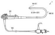
図1に示すように、本実施形態の内視鏡1は、撮像デバイス2が配設されている挿入部9の先端部9Aと、挿入部9の細長い軟性部9Bの基端側に配設された操作部9Cと、操作部9Cから延出するユニバーサルコード9Dと、を含む。なお、先端部9Aに配設された撮像デバイス2から出力された撮像信号は、挿入部9およびユニバーサルコード9Dを挿通する信号ケーブル35(図2参照)を介してプロセッサ(不図示)に伝送される。なお、内視鏡1は医療用であるが、工業用でもよい。<First Embodiment>
As shown in FIG. 1, the
図2および図3に示すように、挿入部9の先端部9Aには、略円筒状のハウジング10が配設されている。例えば、金属からなるハウジング10には、貫通孔H9、H10がある。貫通孔H9は、処理具等が挿通されるチャンネルの開口部を構成している。一方、貫通孔H10には撮像デバイス2が挿入され固定されている。 As shown in FIGS. 2 and 3, a substantially
なお、以下の説明において、各実施形態に基づく図面は、模式的なものであり、各部分の厚みと幅との関係、夫々の部分の厚みの比率などは現実のものとは異なることに留意すべきであり、図面の相互間においても互いの寸法の関係や比率が異なる部分が含まれている場合がある。また、一部の構成要素の図示、符号の付与は省略する場合がある。また、被写体の方向、すなわち、図2等において左方向を、「前方向」、右方向を「後ろ方向」という。In the following description, it should be noted that the drawings based on each embodiment are schematic, and the relationship between the thickness and width of each part, the ratio of the thickness of each part, and the like are different from the actual ones. It should be done, and there may be parts where the relations and ratios of the dimensions of the drawings are different from each other. In addition, illustration of some components and addition of reference numerals may be omitted. Further, the direction of the subject, that is, the left direction in FIG. 2 and the like is referred to as "forward direction", and the right direction is referred to as "backward direction".
撮像デバイス2は、光学ユニット20と撮像ユニット30とを有する。光学ユニット20は、先端レンズ21と、複数の光学部材22(例えば、レンズ22A、フィルタ22B、間隔調整環22C、レンズ22D)と、を含む。 The
先端レンズ21は、石英またはサファイア等の光学材料からなる。先端レンズ21には、安定化ジルコニア(YSZ)、イットリウム・アルミニウム・ガーネット(YAG)などの透明な光学材料を使うことも可能である。また、非結晶質のガラスでもオートクレーブ耐性が高いものは、先端レンズ21に適用可能である。 The
先端レンズ21は広視野を得るために負のパワーを有する平凹レンズである。しかし、先端レンズ21は光学ユニット20の構成によっては平凸レンズでもよい。しかし、先端レンズ21の外面は、付着防止及び衝撃による破損防止のため、平面であることが好ましい。 The
先端レンズ21は、ハウジング10の貫通孔H10の先端部に水密固定されている。ここで、水密とは、液体の水だけでなく水蒸気が隙間から浸入することが防止され、先端レンズ21の内面に結露が発生するおそれの無い状態を意味する。 The
貫通孔H10の前側(被写体側)から貫通孔H10に挿入された先端レンズ21は、例えば、接着剤、ガラスまたは半田等を介して、ハウジング10に直接固定されている。 The
これに対して、光学ユニット20の先端レンズ21以外の複数の光学部材22は、レンズ枠29に保持された状態で、貫通孔H10に後ろ側から挿入されている。 On the other hand, a plurality of
撮像ユニット30は、光学ユニット20が集光した被写体像を電気信号に変換する。撮像ユニット30は、撮像素子31、カバーガラス32、信号処理部33、および信号ケーブル35を含む。撮像ユニット30は、ユニット枠39に収容され、封止樹脂36により隙間が充填されている。 The
レンズ枠29は、ユニット枠39に収容されている撮像素子31との距離が調整されてから、ユニット枠39に強固に固定されている。例えば、レンズ枠29とユニット枠39とは嵌合固定されている。両者の接合部は、さらに、エポキシ等の高弾性率樹脂、または半田により、補強されていてもよい。 The
ハウジング10の貫通孔H10に、後ろ側から挿入された撮像デバイス2は、後部は貫通孔H10から突出している。すなわち、ユニット枠39は前部が貫通孔H10に挿入され、挿入されている前部の外周面が接着剤40を介して貫通孔H10に接着されている。 The
レンズ枠29も、接着剤40を介して貫通孔H10に接着されている。 The
そして、内視鏡1では、先端レンズ21を除く撮像デバイス2を、ハウジング10の貫通孔H10に接着している接着剤40の弾性率が、10MPa以下である。 In the
図4に示すように、内視鏡4では、撮像デバイス2の交換を行う場合、先端レンズ21を除く撮像デバイス2を、ハウジング10から後方に、容易に引き抜くことができる。すなわち、ハウジング10と撮像デバイス2とは、接着剤40を介して接着されているが、弾性率が10MPa以下の接着剤40は剪断応力により容易に破断する。言い替えれば、接着剤40は、ハウジング10に付着した接着剤40Aと、撮像デバイス2に付着した接着剤40Bとに、容易に破断できる。 As shown in FIG. 4, in the endoscope 4, when the
撮像デバイス2を再利用する場合には、撮像デバイス2に付着した接着剤40Bは、有機溶媒等により簡単に除去できる。なお、内視鏡1の撮像デバイス2の再利用は、厳密には、先端レンズ21を除く撮像デバイス2の再利用である。 When the
一方、動作不良の撮像デバイス2を交換する場合にも、ハウジング10に付着した接着剤40Aは簡単に除去できる。先端レンズ21の水密固定は、低融点ガラスまたは半田等を用いるため、繁雑である。しかし、内視鏡1では、ハウジング10に固定されている先端レンズ21は、そのまま利用できるため、さらに交換作業が容易である。 On the other hand, even when the malfunctioning
弾性率(ヤング率)が、10MPa以下の接着剤40としては、軟性シリコーン樹脂、軟質ポリエステル樹脂、軟質塩化ビニル樹脂、またはゴム等を用いることができる。ここで、例えば、シリコーン樹脂であっても、50MPaの樹脂は接着剤40として用いることはできない。もちろん、接着剤として広く使用されている、エポキシ樹脂(弾性率:8GPa)等は、接着剤40には不適である。 As the adhesive 40 having an elastic modulus (Young's modulus) of 10 MPa or less, a soft silicone resin, a soft polyester resin, a soft vinyl chloride resin, rubber, or the like can be used. Here, for example, even if it is a silicone resin, the resin of 50 MPa cannot be used as the adhesive 40. Of course, epoxy resin (elastic modulus: 8 GPa) and the like, which are widely used as adhesives, are not suitable for the adhesive 40.
なお、弾性率(ヤング率)は、例えば、規格(ISO 527-1、JIS K 7161)に基づいて、25℃で測定された引っ張り弾性率である。 The elastic modulus (Young's modulus) is, for example, a tensile elastic modulus measured at 25 ° C. based on a standard (ISO 527-1, JIS K 7161).
接着剤40の弾性率の下限は特に制限は無いが、工業的に容易に入手可能な接着剤では、例えば、0.1MPa以上である。 The lower limit of the elastic modulus of the adhesive 40 is not particularly limited, but an industrially readily available adhesive is, for example, 0.1 MPa or more.
また、弾性率が10MPa以下と極めて軟らかい樹脂からなる接着剤40は、挿入部9の先端部9Aに外部から強い衝撃力が印加されても、撮像デバイス2の振動を吸収する。また、先端レンズ21は、先端レンズ21以外の撮像デバイス2と一体化されていない。このため、内視鏡1の先端レンズ21は耐衝撃性に優れている。 Further, the adhesive 40 made of an extremely soft resin having an elastic modulus of 10 MPa or less absorbs the vibration of the
<第2実施形態>
第2実施形態の内視鏡1Aは、内視鏡1と類似し同じ効果を有するため、同じ機能の構成要素には同じ符号を付し説明は省略する。<Second Embodiment>
Since the
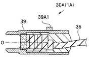
図6および図7に示すように内視鏡1Aでは、撮像ユニット30Aのユニット枠39が、貫通孔H10に挿入されない後部の外周面に、中心軸Oに対して回転対称に配置されている、複数の突起部39A1、39A2、39A3を有する。複数の突起部39A1、39A2、39A3は、ユニット枠39に接合されていてもよいし、ユニット枠39と一体形成されていてもよい。
すなわち、ユニット枠39は外周面に、ハウジング10から撮像デバイス2Aを引き抜くための治具が固定される複数の突起部39A1、39A2、39A3を有する。As shown in FIGS. 6 and 7, in the
That is, the
撮像デバイス2の交換作業において、ハウジング10から撮像デバイス2を引き抜くために、例えば、信号ケーブル35を引っ張ると信号ケーブル35が断線するおそれがあった。また、撮像デバイス2の外周を強い力で把持すると、撮像デバイス2が変形するおそれがあった。 In the replacement work of the
内視鏡1Aでは、撮像デバイス2Aには複数の突起部39A1、39A2、39A3があるため、例えば、突起部39A1等の前側面と当接する治具(不図示)を用いることで、信号ケーブル35および撮像デバイス2を損傷することなく、容易にハウジング10から撮像デバイス2Aを引き抜くことができる。
すなわち、内視鏡1Aの撮像デバイスの交換方法は、複数の突起部39A1、39A2、39A3に、治具が固定される工程と、挿入部9の先端部9Aが保持された状態において、治具を内視鏡9の基端側に引くことによって、ハウジング10から先端レンズ21以外の撮像デバイス2が引き抜かれる工程と、を具備する。In the
That is, the method of exchanging the imaging device of the
<第2実施形態の変形例>
第2実施形態の変形例の内視鏡1Bは、内視鏡1Aと類似しているため、同じ機能の構成要素には同じ符号を付し説明は省略する。<Modified example of the second embodiment>
Since the
図6に示すように内視鏡1Bでは、撮像ユニット30Bは撮像素子31の外形に合わせて、略直方体である。図示しないが光学ユニット20は、内視鏡1と同じように略円筒形である。 As shown in FIG. 6, in the
撮像ユニット30Bはユニット枠39の外周面に、中心軸Oに対して回転対称に配置されている2つの突起部39B1、39B2がある。 The
このため、内視鏡1Bは、内視鏡1Aと同じ効果を有する。 Therefore, the
<第3実施形態>
第3実施形態の内視鏡1Cは、内視鏡1と類似し同じ効果を有するため、同じ機能の構成要素には同じ符号を付し説明は省略する。<Third Embodiment>
Since the
図8に示すように、内視鏡1Cでは、ユニット枠39の前部と接着剤40との間、およびレンズ枠29と接着剤40との間、すなわち、ユニット枠39とレンズ枠29との接合部に、離型剤50がコーティングされている。離型剤50は、接着剤40の接合部との接着力を弱くする。なお、離型剤50は、ハウジング10の貫通孔H10の接合部と対向する領域にコーティングされていてもよい。As shown in FIG. 8, between the
離型剤50は、例えば、市販されている、フッ素系離型剤またはシリコーン系離型剤を用いる。離型剤50は、液体でもよいし、粘性の高いゲル状でもよい。 As the
撮像デバイス2の交換作業において、ハウジング10から撮像デバイス2を引き抜くときに、ユニット枠39とレンズ枠29との接合部に大きな応力が印加されると、接合部が損傷するおそれがある。 In the replacement work of the
内視鏡1Cは、ハウジング10から撮像デバイス2を引き抜くときに、ユニット枠39とレンズ枠29との接合部に大きな応力が印加されるおそれがない。 In the
<第3実施形態の変形例>
第3実施形態の変形例の内視鏡1Dは、内視鏡1Cと類似しているため、同じ機能の構成要素には同じ符号を付し説明は省略する。<Modified example of the third embodiment>
Since the endoscope 1D of the modified example of the third embodiment is similar to the
図9に示すように、内視鏡1Dでは、ユニット枠39の先端部と接着剤40との間、およびレンズ枠29と接着剤40との間、すなわち、ユニット枠39とレンズ枠29との接合部を覆う環状部材55が配設されている。例えば、環状部材55はシリコーンゴムチューブからなる。 As shown in FIG. 9, in the endoscope 1D, between the tip of the
内視鏡1Dは、環状部材55により接合部は接着剤40により接着されていない。すなわち、環状部材55は接合部を覆っているだけである。このため、内視鏡1Dでは、ハウジング10から撮像デバイス2を引き抜くときに、ユニット枠39とレンズ枠29との接合部に大きな応力が印加されるおそれがない。 In the endoscope 1D, the joint portion is not adhered by the adhesive 40 by the
なお、内視鏡1C、1Dにおいても、ユニット枠39が後部の外周面に中心軸に対して回転対称に配置されている複数の突起部を有していれば、内視鏡1A、1Bと同じ効果を有することは言うまでも無い。 Even in the
本発明は上述した実施形態および変形例等に限定されるものではなく、本発明の要旨を変えない範囲において、種々の変更、組み合わせ、及び改変等ができる。 The present invention is not limited to the above-described embodiments and modifications, and various modifications, combinations, modifications, and the like can be made without changing the gist of the present invention.
本出願は、2017年8月29日に日本国に出願された特願2017−164705号を優先権主張の基礎として出願するものであり、上記の開示内容は、本願明細書、請求の範囲に引用されるものとする。 This application is filed based on Japanese Patent Application No. 2017-164705 filed in Japan on August 29, 2017 as the basis for claiming priority, and the above disclosure contents are within the scope of the present specification and claims. It shall be quoted.
1、1A〜1D…内視鏡
2…撮像デバイス
4…内視鏡
9…挿入部
9A…先端部
9B…軟性部
9C…操作部
9D…ユニバーサルコード
10…ハウジング
20…光学ユニット
21…先端レンズ
22…光学部材
22A…レンズ
22B…フィルタ
22C…絞り
22D…レンズ
29…レンズ枠
30…撮像ユニット
31…撮像素子
32…カバーガラス
33…信号処理部
35…信号ケーブル
36…封止樹脂
39…ユニット枠
39A1、39A2、39A3…突起部
39B1、39B2…突起部
40…接着剤
50…離型剤
55…環状部材
H9、H10…貫通孔
O…中心軸1, 1A to 1D ...
Claims (5)
Translated fromJapanese前記撮像デバイスが、
先端レンズおよび複数の光学部材を含む光学ユニットと、
前記光学ユニットが集光した被写体像を電気信号に変換する撮像ユニットと、を有し、
前記先端レンズは、前記貫通孔の先端部に水密固定されており、
前記複数の光学部材はレンズ枠によって保持されており、前記レンズ枠は前記貫通孔に挿入され、前記レンズ枠の一部が接着剤を用いて前記貫通孔に接着されており、
前記撮像ユニットは、前記レンズ枠と固定されているユニット枠を有し、前記ユニット枠は前部が前記貫通孔に挿入され、前記前部が前記接着剤を用いて前記貫通孔に接着されており、
前記接着剤の弾性率が、0.1MPa以上10MPa以下であり、
前記ユニット枠が、前記貫通孔に挿入されていない後部の外周面に複数の突起部を有することを特徴とする内視鏡。An endoscope in which a housing having a through hole is arranged at the tip of the insertion portion, and an imaging device inserted into the through hole is fixed to the through hole.
The imaging device
An optical unit that includes a tip lens and multiple optics,
It has an image pickup unit that converts a subject image focused by the optical unit into an electric signal, and has an image pickup unit.
The tip lens is watertightly fixed to the tip of the through hole.
The plurality of optical members are held by a lens frame, the lens frame is inserted into the through hole, and a part of the lens frame is adhered to the through hole using an adhesive.
The imaging unit has a unit frame fixed to the lens frame, and the front portion of the unit frame is inserted into the through hole, and the front portion is adhered to the through hole using the adhesive. Glue,
The elastic modulus of the adhesive is 0.1 MPa or more and 10 MPa or less.
An endoscope characterized in that the unit frame has a plurality of protrusions on an outer peripheral surface of a rear portion that is not inserted into the through hole.
前記貫通孔に挿入され、前記貫通孔に固定されている撮像デバイスと、を具備する内視鏡の撮像デバイスの交換方法であって、It is a method of exchanging an image pickup device of an endoscope provided with an image pickup device inserted into the through hole and fixed to the through hole.
前記撮像デバイスが、先端レンズおよび複数の光学部材を含む光学ユニットと、前記光学ユニットが集光した被写体像を電気信号に変換する撮像ユニットと、を有し、The imaging device includes an optical unit including a tip lens and a plurality of optical members, and an imaging unit that converts a subject image focused by the optical unit into an electric signal.
前記先端レンズは、前記貫通孔の先端部に水密固定されており、The tip lens is watertightly fixed to the tip of the through hole.
前記複数の光学部材はレンズ枠によって保持されており、前記レンズ枠は前記貫通孔に挿入され、前記レンズ枠の一部は、弾性率が、0.1Mpa以上10Mpa以下である接着剤を用いて前記貫通孔に接着されており、The plurality of optical members are held by a lens frame, the lens frame is inserted into the through hole, and a part of the lens frame uses an adhesive having an elastic modulus of 0.1 Mpa or more and 10 Mpa or less. It is adhered to the through hole and
前記撮像ユニットは、前記レンズ枠と固定されているユニット枠を有し、前記ユニット枠は前部が前記貫通孔に挿入され、前記前部が前記接着剤を用いて前記貫通孔に接着されており、前記貫通孔に挿入されていない後部の外周面に、治具が固定される複数の突起部を有し、The imaging unit has a unit frame fixed to the lens frame, and the front portion of the unit frame is inserted into the through hole, and the front portion is adhered to the through hole using the adhesive. It has a plurality of protrusions on which the jig is fixed on the outer peripheral surface of the rear portion that is not inserted into the through hole.
前記複数の突起部に、前記治具が固定される工程と、The process of fixing the jig to the plurality of protrusions and
前記挿入部の前記先端部が保持された状態において、前記治具を前記内視鏡の基端側に引くことによって、前記ハウジングから前記先端レンズ以外の撮像デバイスが引き抜かれる工程と、を具備することを特徴とする内視鏡の撮像デバイスの交換方法。A step of pulling an imaging device other than the tip lens from the housing by pulling the jig toward the base end side of the endoscope while the tip portion of the insertion portion is held is provided. A method of exchanging an imaging device for an endoscope.
Applications Claiming Priority (3)
| Application Number | Priority Date | Filing Date | Title |
|---|---|---|---|
| JP2017164705 | 2017-08-29 | ||
| JP2017164705 | 2017-08-29 | ||
| PCT/JP2018/018804WO2019044053A1 (en) | 2017-08-29 | 2018-05-15 | Endoscope |
Publications (2)
| Publication Number | Publication Date |
|---|---|
| JPWO2019044053A1 JPWO2019044053A1 (en) | 2020-08-27 |
| JP6860959B2true JP6860959B2 (en) | 2021-04-21 |
Family
ID=65525001
Family Applications (1)
| Application Number | Title | Priority Date | Filing Date |
|---|---|---|---|
| JP2019538966AActiveJP6860959B2 (en) | 2017-08-29 | 2018-05-15 | How to replace the endoscope and the imaging device of the endoscope |
Country Status (4)
| Country | Link |
|---|---|
| US (1) | US10932652B2 (en) |
| JP (1) | JP6860959B2 (en) |
| CN (1) | CN111031884B (en) |
| WO (1) | WO2019044053A1 (en) |
Families Citing this family (16)
| Publication number | Priority date | Publication date | Assignee | Title |
|---|---|---|---|---|
| WO2018098465A1 (en) | 2016-11-28 | 2018-05-31 | Inventio, Inc. | Endoscope with separable, disposable shaft |
| EP3539445A1 (en) | 2018-03-14 | 2019-09-18 | Ambu A/S | Method for manufacturing a tip housing |
| EP3613327A1 (en) | 2018-08-24 | 2020-02-26 | Ambu A/S | A tip part for a vision device |
| EP3708061A1 (en)* | 2019-03-14 | 2020-09-16 | Ambu A/S | A tip part for an endoscope |
| US11794389B2 (en)* | 2019-09-06 | 2023-10-24 | Ambu A/S | Tip part assembly for an endoscope |
| USD1018844S1 (en) | 2020-01-09 | 2024-03-19 | Adaptivendo Llc | Endoscope handle |
| EP3858217A1 (en)* | 2020-01-28 | 2021-08-04 | Ambu A/S | A tip part of an endoscope |
| JP7216034B2 (en)* | 2020-02-13 | 2023-01-31 | 富士フイルム株式会社 | Endoscope and how to disassemble the endoscope |
| DE102020111455A1 (en)* | 2020-04-27 | 2021-10-28 | Schölly Fiberoptic GmbH | Flexible endoscope based on an investment material |
| DE102020111458A1 (en) | 2020-04-27 | 2021-10-28 | Schölly Fiberoptic GmbH | Flexible endoscope with a skeletal structure |
| USD1051380S1 (en) | 2020-11-17 | 2024-11-12 | Adaptivendo Llc | Endoscope handle |
| WO2022168865A1 (en)* | 2021-02-04 | 2022-08-11 | 富士フイルム株式会社 | Endoscope |
| USD1031035S1 (en) | 2021-04-29 | 2024-06-11 | Adaptivendo Llc | Endoscope handle |
| USD1070082S1 (en) | 2021-04-29 | 2025-04-08 | Adaptivendo Llc | Endoscope handle |
| US11839356B2 (en)* | 2021-08-19 | 2023-12-12 | Chia-Ling Wu | Endoscope decontamination sheath |
| USD1066659S1 (en) | 2021-09-24 | 2025-03-11 | Adaptivendo Llc | Endoscope handle |
Family Cites Families (17)
| Publication number | Priority date | Publication date | Assignee | Title |
|---|---|---|---|---|
| JPH0621252A (en)* | 1992-07-01 | 1994-01-28 | Oki Electric Ind Co Ltd | Mounting structure for large bare chip ic on circuit board |
| JPH11155805A (en)* | 1997-12-02 | 1999-06-15 | Olympus Optical Co Ltd | Endoscope |
| JP2001128930A (en) | 1999-11-01 | 2001-05-15 | Olympus Optical Co Ltd | Endoscope |
| JP3981263B2 (en)* | 2001-12-06 | 2007-09-26 | オリンパス株式会社 | Electronic endoscope |
| JP3772147B2 (en)* | 2002-12-24 | 2006-05-10 | オリンパス株式会社 | Endoscope |
| JP2005227728A (en)* | 2004-02-16 | 2005-08-25 | Pentax Corp | Lens assembly manufacturing method, lens assembly, and endoscope |
| JP2005287633A (en)* | 2004-03-31 | 2005-10-20 | Fujinon Corp | Insertion section fracture preventing device for endoscope |
| JP5143332B2 (en)* | 2004-07-05 | 2013-02-13 | オリンパス株式会社 | Imaging device, fixing member for imaging device, and method of repairing imaging device |
| EP1769719A4 (en)* | 2004-07-05 | 2009-10-21 | Olympus Medical Systems Corp | ELECTRONIC ENDOSCOPE |
| JP4578904B2 (en)* | 2004-09-13 | 2010-11-10 | 富士フイルム株式会社 | Endoscope |
| JP4928974B2 (en)* | 2007-02-19 | 2012-05-09 | Hoya株式会社 | The tip of the electronic endoscope |
| JP5011024B2 (en)* | 2007-08-10 | 2012-08-29 | オリンパスメディカルシステムズ株式会社 | Endoscope |
| JP2010267541A (en)* | 2009-05-15 | 2010-11-25 | Canon Inc | Display panel and image display device |
| WO2013084561A1 (en)* | 2011-12-08 | 2013-06-13 | オリンパスメディカルシステムズ株式会社 | Endoscope |
| JP5505578B1 (en)* | 2012-12-12 | 2014-05-28 | コニカミノルタ株式会社 | probe |
| JP2016522022A (en)* | 2013-04-29 | 2016-07-28 | エンドチョイス インコーポレイテッドEndochoice, Inc. | Video processing in small multi-view element endoscope system |
| JP6006458B1 (en)* | 2014-11-19 | 2016-10-12 | オリンパス株式会社 | Endoscope imaging unit |
- 2018
- 2018-05-15JPJP2019538966Apatent/JP6860959B2/enactiveActive
- 2018-05-15WOPCT/JP2018/018804patent/WO2019044053A1/ennot_activeCeased
- 2018-05-15CNCN201880053787.4Apatent/CN111031884B/enactiveActive
- 2020
- 2020-02-12USUS16/788,436patent/US10932652B2/enactiveActive
Also Published As
| Publication number | Publication date |
|---|---|
| JPWO2019044053A1 (en) | 2020-08-27 |
| CN111031884A (en) | 2020-04-17 |
| US20200297193A1 (en) | 2020-09-24 |
| US10932652B2 (en) | 2021-03-02 |
| WO2019044053A1 (en) | 2019-03-07 |
| CN111031884B (en) | 2022-07-08 |
Similar Documents
| Publication | Publication Date | Title |
|---|---|---|
| JP6860959B2 (en) | How to replace the endoscope and the imaging device of the endoscope | |
| JP5143332B2 (en) | Imaging device, fixing member for imaging device, and method of repairing imaging device | |
| JP6326561B1 (en) | Endoscope, endoscope manufacturing method | |
| US9998641B2 (en) | Image pickup unit provided in endoscope | |
| JP5566559B1 (en) | Endoscope | |
| CN106455924B (en) | Camera unit for endoscope | |
| CN104968254B (en) | endoscope | |
| JP2014188170A (en) | Endoscope and endoscope system | |
| JP6057595B2 (en) | Endoscope | |
| JP4722912B2 (en) | Endoscope, endoscope manufacturing method | |
| JP3981263B2 (en) | Electronic endoscope | |
| JP4477165B2 (en) | Endoscope | |
| JP4928975B2 (en) | The tip of the electronic endoscope | |
| JP5366722B2 (en) | Endoscope | |
| JP2001112708A (en) | Endoscope | |
| JP4928974B2 (en) | The tip of the electronic endoscope | |
| JP6095525B2 (en) | Lens unit, endoscope having lens unit | |
| JP4652843B2 (en) | Endoscope | |
| JP4160577B2 (en) | Imaging device | |
| JP3325237B2 (en) | Endoscope | |
| JP6099382B2 (en) | Lens device and endoscope | |
| JP2002301016A (en) | Endoscope | |
| JP6460928B2 (en) | Insertion device | |
| US20130165751A1 (en) | Waterproof endoscope and a method of manufacturing the same |
Legal Events
| Date | Code | Title | Description |
|---|---|---|---|
| A521 | Request for written amendment filed | Free format text:JAPANESE INTERMEDIATE CODE: A523 Effective date:20200205 | |
| A621 | Written request for application examination | Free format text:JAPANESE INTERMEDIATE CODE: A621 Effective date:20200205 | |
| A131 | Notification of reasons for refusal | Free format text:JAPANESE INTERMEDIATE CODE: A131 Effective date:20201027 | |
| A521 | Request for written amendment filed | Free format text:JAPANESE INTERMEDIATE CODE: A523 Effective date:20201207 | |
| A131 | Notification of reasons for refusal | Free format text:JAPANESE INTERMEDIATE CODE: A131 Effective date:20210126 | |
| A521 | Request for written amendment filed | Free format text:JAPANESE INTERMEDIATE CODE: A523 Effective date:20210302 | |
| TRDD | Decision of grant or rejection written | ||
| A01 | Written decision to grant a patent or to grant a registration (utility model) | Free format text:JAPANESE INTERMEDIATE CODE: A01 Effective date:20210316 | |
| A61 | First payment of annual fees (during grant procedure) | Free format text:JAPANESE INTERMEDIATE CODE: A61 Effective date:20210326 | |
| R151 | Written notification of patent or utility model registration | Ref document number:6860959 Country of ref document:JP Free format text:JAPANESE INTERMEDIATE CODE: R151 | |
| R250 | Receipt of annual fees | Free format text:JAPANESE INTERMEDIATE CODE: R250 | |
| R250 | Receipt of annual fees | Free format text:JAPANESE INTERMEDIATE CODE: R250 |