JP6859811B2 - Liquid drainer - Google Patents
Liquid drainerDownload PDFInfo
- Publication number
- JP6859811B2 JP6859811B2JP2017072943AJP2017072943AJP6859811B2JP 6859811 B2JP6859811 B2JP 6859811B2JP 2017072943 AJP2017072943 AJP 2017072943AJP 2017072943 AJP2017072943 AJP 2017072943AJP 6859811 B2JP6859811 B2JP 6859811B2
- Authority
- JP
- Japan
- Prior art keywords
- liquid
- flow path
- liquid chamber
- amount
- cartridge
- Prior art date
- Legal status (The legal status is an assumption and is not a legal conclusion. Google has not performed a legal analysis and makes no representation as to the accuracy of the status listed.)
- Active
Links
- 239000007788liquidSubstances0.000titleclaimsdescription474
- 230000004044responseEffects0.000claimsdescription45
- 230000007423decreaseEffects0.000claimsdescription13
- 238000005259measurementMethods0.000claimsdescription11
- 238000007599dischargingMethods0.000claimsdescription7
- 239000000976inkSubstances0.000description247
- 238000000034methodMethods0.000description96
- 230000008569processEffects0.000description95
- 238000012545processingMethods0.000description31
- 238000004891communicationMethods0.000description28
- 230000006870functionEffects0.000description23
- 238000001514detection methodMethods0.000description10
- 238000005192partitionMethods0.000description7
- 230000008859changeEffects0.000description6
- 238000012856packingMethods0.000description5
- 238000012423maintenanceMethods0.000description4
- 239000000463materialSubstances0.000description3
- 230000000149penetrating effectEffects0.000description3
- 230000001133accelerationEffects0.000description2
- 239000012528membraneSubstances0.000description2
- 230000003287optical effectEffects0.000description2
- 238000012546transferMethods0.000description2
- XLYOFNOQVPJJNP-UHFFFAOYSA-NwaterSubstancesOXLYOFNOQVPJJNP-UHFFFAOYSA-N0.000description2
- 230000004308accommodationEffects0.000description1
- 230000009471actionEffects0.000description1
- 238000004140cleaningMethods0.000description1
- 239000003086colorantSubstances0.000description1
- 238000010586diagramMethods0.000description1
- 230000000694effectsEffects0.000description1
- 230000005484gravityEffects0.000description1
- 238000003780insertionMethods0.000description1
- 230000037431insertionEffects0.000description1
- 239000004973liquid crystal related substanceSubstances0.000description1
- 230000008531maintenance mechanismEffects0.000description1
- 230000005055memory storageEffects0.000description1
- 238000012986modificationMethods0.000description1
- 230000004048modificationEffects0.000description1
- 230000002093peripheral effectEffects0.000description1
- 239000011347resinSubstances0.000description1
- 229920005989resinPolymers0.000description1
- 230000000717retained effectEffects0.000description1
Images


Classifications
- B—PERFORMING OPERATIONS; TRANSPORTING
- B41—PRINTING; LINING MACHINES; TYPEWRITERS; STAMPS
- B41J—TYPEWRITERS; SELECTIVE PRINTING MECHANISMS, i.e. MECHANISMS PRINTING OTHERWISE THAN FROM A FORME; CORRECTION OF TYPOGRAPHICAL ERRORS
- B41J2/00—Typewriters or selective printing mechanisms characterised by the printing or marking process for which they are designed
- B41J2/005—Typewriters or selective printing mechanisms characterised by the printing or marking process for which they are designed characterised by bringing liquid or particles selectively into contact with a printing material
- B41J2/01—Ink jet
- B41J2/17—Ink jet characterised by ink handling
- B41J2/175—Ink supply systems ; Circuit parts therefor
- B41J2/17566—Ink level or ink residue control
- B—PERFORMING OPERATIONS; TRANSPORTING
- B41—PRINTING; LINING MACHINES; TYPEWRITERS; STAMPS
- B41J—TYPEWRITERS; SELECTIVE PRINTING MECHANISMS, i.e. MECHANISMS PRINTING OTHERWISE THAN FROM A FORME; CORRECTION OF TYPOGRAPHICAL ERRORS
- B41J2/00—Typewriters or selective printing mechanisms characterised by the printing or marking process for which they are designed
- B41J2/005—Typewriters or selective printing mechanisms characterised by the printing or marking process for which they are designed characterised by bringing liquid or particles selectively into contact with a printing material
- B41J2/01—Ink jet
- B41J2/17—Ink jet characterised by ink handling
- B41J2/175—Ink supply systems ; Circuit parts therefor
- B41J2/17503—Ink cartridges
- B41J2/17506—Refilling of the cartridge
- B41J2/17509—Whilst mounted in the printer
- B—PERFORMING OPERATIONS; TRANSPORTING
- B41—PRINTING; LINING MACHINES; TYPEWRITERS; STAMPS
- B41J—TYPEWRITERS; SELECTIVE PRINTING MECHANISMS, i.e. MECHANISMS PRINTING OTHERWISE THAN FROM A FORME; CORRECTION OF TYPOGRAPHICAL ERRORS
- B41J2/00—Typewriters or selective printing mechanisms characterised by the printing or marking process for which they are designed
- B41J2/005—Typewriters or selective printing mechanisms characterised by the printing or marking process for which they are designed characterised by bringing liquid or particles selectively into contact with a printing material
- B41J2/01—Ink jet
- B41J2/17—Ink jet characterised by ink handling
- B41J2/175—Ink supply systems ; Circuit parts therefor
- B41J2/17503—Ink cartridges
- B41J2/17513—Inner structure
- B—PERFORMING OPERATIONS; TRANSPORTING
- B41—PRINTING; LINING MACHINES; TYPEWRITERS; STAMPS
- B41J—TYPEWRITERS; SELECTIVE PRINTING MECHANISMS, i.e. MECHANISMS PRINTING OTHERWISE THAN FROM A FORME; CORRECTION OF TYPOGRAPHICAL ERRORS
- B41J2/00—Typewriters or selective printing mechanisms characterised by the printing or marking process for which they are designed
- B41J2/005—Typewriters or selective printing mechanisms characterised by the printing or marking process for which they are designed characterised by bringing liquid or particles selectively into contact with a printing material
- B41J2/01—Ink jet
- B41J2/17—Ink jet characterised by ink handling
- B41J2/175—Ink supply systems ; Circuit parts therefor
- B41J2/17503—Ink cartridges
- B41J2/1752—Mounting within the printer
- B41J2/17523—Ink connection
- B—PERFORMING OPERATIONS; TRANSPORTING
- B41—PRINTING; LINING MACHINES; TYPEWRITERS; STAMPS
- B41J—TYPEWRITERS; SELECTIVE PRINTING MECHANISMS, i.e. MECHANISMS PRINTING OTHERWISE THAN FROM A FORME; CORRECTION OF TYPOGRAPHICAL ERRORS
- B41J2/00—Typewriters or selective printing mechanisms characterised by the printing or marking process for which they are designed
- B41J2/005—Typewriters or selective printing mechanisms characterised by the printing or marking process for which they are designed characterised by bringing liquid or particles selectively into contact with a printing material
- B41J2/01—Ink jet
- B41J2/17—Ink jet characterised by ink handling
- B41J2/175—Ink supply systems ; Circuit parts therefor
- B41J2/17503—Ink cartridges
- B41J2/17526—Electrical contacts to the cartridge
- B41J2/1753—Details of contacts on the cartridge, e.g. protection of contacts
- B—PERFORMING OPERATIONS; TRANSPORTING
- B41—PRINTING; LINING MACHINES; TYPEWRITERS; STAMPS
- B41J—TYPEWRITERS; SELECTIVE PRINTING MECHANISMS, i.e. MECHANISMS PRINTING OTHERWISE THAN FROM A FORME; CORRECTION OF TYPOGRAPHICAL ERRORS
- B41J2/00—Typewriters or selective printing mechanisms characterised by the printing or marking process for which they are designed
- B41J2/005—Typewriters or selective printing mechanisms characterised by the printing or marking process for which they are designed characterised by bringing liquid or particles selectively into contact with a printing material
- B41J2/01—Ink jet
- B41J2/17—Ink jet characterised by ink handling
- B41J2/175—Ink supply systems ; Circuit parts therefor
- B41J2/17503—Ink cartridges
- B41J2/17543—Cartridge presence detection or type identification
- B41J2/17546—Cartridge presence detection or type identification electronically
- B—PERFORMING OPERATIONS; TRANSPORTING
- B41—PRINTING; LINING MACHINES; TYPEWRITERS; STAMPS
- B41J—TYPEWRITERS; SELECTIVE PRINTING MECHANISMS, i.e. MECHANISMS PRINTING OTHERWISE THAN FROM A FORME; CORRECTION OF TYPOGRAPHICAL ERRORS
- B41J2/00—Typewriters or selective printing mechanisms characterised by the printing or marking process for which they are designed
- B41J2/005—Typewriters or selective printing mechanisms characterised by the printing or marking process for which they are designed characterised by bringing liquid or particles selectively into contact with a printing material
- B41J2/01—Ink jet
- B41J2/17—Ink jet characterised by ink handling
- B41J2/175—Ink supply systems ; Circuit parts therefor
- B41J2/17503—Ink cartridges
- B41J2/17553—Outer structure
- B—PERFORMING OPERATIONS; TRANSPORTING
- B41—PRINTING; LINING MACHINES; TYPEWRITERS; STAMPS
- B41J—TYPEWRITERS; SELECTIVE PRINTING MECHANISMS, i.e. MECHANISMS PRINTING OTHERWISE THAN FROM A FORME; CORRECTION OF TYPOGRAPHICAL ERRORS
- B41J29/00—Details of, or accessories for, typewriters or selective printing mechanisms not otherwise provided for
- B41J29/12—Guards, shields or dust excluders
- B41J29/13—Cases or covers
- B—PERFORMING OPERATIONS; TRANSPORTING
- B41—PRINTING; LINING MACHINES; TYPEWRITERS; STAMPS
- B41J—TYPEWRITERS; SELECTIVE PRINTING MECHANISMS, i.e. MECHANISMS PRINTING OTHERWISE THAN FROM A FORME; CORRECTION OF TYPOGRAPHICAL ERRORS
- B41J29/00—Details of, or accessories for, typewriters or selective printing mechanisms not otherwise provided for
- B41J29/38—Drives, motors, controls or automatic cut-off devices for the entire printing mechanism
- B—PERFORMING OPERATIONS; TRANSPORTING
- B41—PRINTING; LINING MACHINES; TYPEWRITERS; STAMPS
- B41J—TYPEWRITERS; SELECTIVE PRINTING MECHANISMS, i.e. MECHANISMS PRINTING OTHERWISE THAN FROM A FORME; CORRECTION OF TYPOGRAPHICAL ERRORS
- B41J2/00—Typewriters or selective printing mechanisms characterised by the printing or marking process for which they are designed
- B41J2/005—Typewriters or selective printing mechanisms characterised by the printing or marking process for which they are designed characterised by bringing liquid or particles selectively into contact with a printing material
- B41J2/01—Ink jet
- B41J2/17—Ink jet characterised by ink handling
- B41J2/175—Ink supply systems ; Circuit parts therefor
- B41J2/17566—Ink level or ink residue control
- B41J2002/17576—Ink level or ink residue control using a floater for ink level indication
Landscapes
- Ink Jet (AREA)
Description
Translated fromJapanese本発明は、液体を排出する液体排出装置に関する。 The present invention relates to a liquid discharge device that discharges a liquid.
従来より、着脱可能なメインタンクと、装着されたメインタンクから供給されたインクを貯留するサブタンクと、サブタンクに貯留されたインクを吐出して画像を記録する画像記録ユニットとを備えるインクジェットプリンタが知られている(例えば、特許文献1)。また、上記インクジェットプリンタは、メインタンク及びサブタンクの内部空間が大気に開放されている。そのため、メインタンクをインクジェトプリンタに装着すると、メインタンクの内部空間の水頭及びサブタンクの内部空間の水頭の差(以下、「水頭差」と標記する。)によって、メインタンク及びサブタンクの液面が同一高さに揃うように、水頭圧によってインクが移動する。そして、上記インクジェットプリンタは、残量検出センサで検出したインクの残量が閾値未満になったことに応じて、ディスプレイにエンプティを表示したり、画像記録ユニットによるインクの吐出を禁止したりする。 Conventionally, an inkjet printer equipped with a detachable main tank, a sub tank for storing ink supplied from the mounted main tank, and an image recording unit for ejecting ink stored in the sub tank and recording an image has been known. (For example, Patent Document 1). Further, in the inkjet printer, the internal spaces of the main tank and the sub tank are open to the atmosphere. Therefore, when the main tank is attached to the ink jet printer, the liquid levels of the main tank and the sub tank are the same due to the difference between the head in the internal space of the main tank and the head in the internal space of the sub tank (hereinafter referred to as "head difference"). The ink moves by the head pressure so that it is aligned with the height. Then, the inkjet printer displays emptyness on the display or prohibits ink ejection by the image recording unit according to the remaining amount of ink detected by the remaining amount detection sensor becoming less than the threshold value.
上記インクジェットプリンタでは、画像記録ユニットによるインクの吐出を禁止する際には、サブタンクから画像記録ユニットに至るインクの流路に空気が進入しない程度に、サブタンクにインクが貯留されている。これにより、上記インクジェットプリンタでは、当該流路に空気が進入する所謂エアインが抑制できる。一方、上記インクジェットプリンタにおいては、メインタンクが貯留するインクが完全に消費されても、サブタンクには未だインクが貯留されている。したがって、メインタンクのインクが消費された後も、エアインが生じる液面高さまでは、インクの吐出を禁止せずに、サブタンクに貯留されたインクを使用することが可能である。エアインが生じる高さまでインクを使用可能とすることにより、メインタンクを交換するタイミングに時間的な余裕が生じる。すなわち、メインタンクのインクが消費された後も、サブタンクからエアインが生じるまで画像記録が可能となる。そして、サブタンクにおけるインクの液面がエアインのおそれがある高さとなれば、画像記録ユニットによるインクの吐出が禁止される。 In the inkjet printer, when the ink ejection by the image recording unit is prohibited, the ink is stored in the sub tank to the extent that air does not enter the ink flow path from the sub tank to the image recording unit. As a result, in the inkjet printer, so-called air-in in which air enters the flow path can be suppressed. On the other hand, in the inkjet printer, even if the ink stored in the main tank is completely consumed, the ink is still stored in the sub tank. Therefore, even after the ink in the main tank is consumed, it is possible to use the ink stored in the sub tank without prohibiting the ejection of the ink at the liquid level where air-in occurs. By making it possible to use ink up to the height at which air-in occurs, there is time to spare when replacing the main tank. That is, even after the ink in the main tank is consumed, the image can be recorded until air-in is generated from the sub tank. Then, when the liquid level of the ink in the sub tank reaches a height at which there is a risk of air-in, the ink ejection by the image recording unit is prohibited.
メインタンクが交換されると、メインタンクからサブタンクへインクが流出する。仮に、サブタンクにも残量検出センサが設けられていれば、メインタンクからサブタンクへインクが流れ込み、やがて、残量検出センサの検知信号が変化する。残量検出センサの検知信号が変化すると、ディスプレイにおけるエンプティの表示を消去したり、インクの吐出の禁止を解除したりすることができる。しかしながら、メインタンクからサブタンクへインクが流出して、残量検出センサが出力する信号が変化するまでに時間を要すると、メインタンクを交換したユーザは、ディスプレイにおけるエンプティの表示か消えないことから、装置の故障やメインタンクの交換の不備を想定するおそれがある。また、メインタンクを交換した後、画像記録を行うまでユーザを待たせるという不都合が生じるおそれがある。 When the main tank is replaced, ink flows from the main tank to the sub tank. If the sub tank is also provided with the remaining amount detection sensor, ink will flow from the main tank to the sub tank, and eventually the detection signal of the remaining amount detection sensor will change. When the detection signal of the remaining amount detection sensor changes, the empty display on the display can be erased or the prohibition of ink ejection can be lifted. However, if it takes time for the ink to flow out from the main tank to the sub tank and the signal output by the remaining amount detection sensor changes, the user who replaced the main tank will see the empty display on the display or not disappear. There is a risk of equipment failure or improper replacement of the main tank. In addition, after replacing the main tank, there is a possibility that the user may have to wait until the image is recorded.
本発明は、前述された事情に鑑みてなされたものであり、その目的は、第1液室を有するカートリッジが交換されてから、液面センサが、第2液室内の液面が境界位置以上となる信号を出力する前に、報知機の作動を解除することができる手段を提供することにある。 The present invention has been made in view of the above-mentioned circumstances, and an object of the present invention is that after the cartridge having the first liquid chamber is replaced, the liquid level sensor detects the liquid level in the second liquid chamber at the boundary position or higher. It is an object of the present invention to provide a means capable of deactivating the alarm before outputting the signal.
(1) 本発明に係る液体排出装置は、液体が貯留された第1液室、一端が上記第1液室と連通され且つ他端が外部と連通される第1流路、及び一端が上記第1液室と連通され且つ他端が外部と連通される第2流路を有するカートリッジが装着される装着ケースと、第2液室を有するタンクであって、一端が外部と連通され且つ他端が上記第2液室と連通される第3流路であって、上記カートリッジが上記装着ケースに装着されたときに、上記第1液室及び上記第2液室を連通させる流路を、上記第1流路と共に構成する上記第3流路と、上記第3流路よりも下方に位置する一端が上記第2液室と連通される第4流路と、一端が上記第2液室に連通され且つ他端が外部と連通される第5流路と、を有する上記タンクと、上記第4流路の他端と連通されるヘッドと、液面センサと、装着センサと、報知機と、接点と、コントローラと、を備える。上記カートリッジは、上記カートリッジが上記装着ケースに装着された状態で上記接点と導通可能なカートリッジメモリを備えている。上記コントローラは、上記第2液室内の液面の位置が境界位置以上であることに応じて上記液面センサが出力する第1信号を、上記液面センサから受信し、上記第2液室内の液面の位置が上記境界位置未満であることに応じて上記液面センサが出力する第2信号を、上記第1信号の受信後に、上記液面センサから受信し、上記第2信号の受信後に、上記ヘッドを通じて液体を排出させる排出指示を受け付け、上記排出指示で排出が指示された液体の量に相当する値でカウント値を閾値に近づく向きに更新し、上記カウント値が上記閾値に達したことに応じて、上記報知機を作動させ、上記装着ケースに上記カートリッジが装着されていないことに応じて上記装着センサが出力する第3信号を、上記装着センサから受信し、上記装着ケースに上記カートリッジが装着されていることに応じて上記装着センサが出力する第4信号を、上記第3信号を受信した後に、上記装着センサから受信し、上記第3信号を受信した後に、上記第4信号を上記装着センサから受信したことに応じて、上記第1液室に貯留されている液体量Vcを上記カートリッジメモリから読み出し、読み出された上記液体量Vcに基づいて、上記第1液室から上記第2液室へ期間Δtに流出する液体の流出量Qcを算出し、算出された上記流出量Qcが第1閾値以上であること及び上記報知機を作動させていることに応じて、上記報知機の作動を解除する。 (1) The liquid discharge device according to the present invention has a first liquid chamber in which a liquid is stored, a first flow path having one end communicating with the first liquid chamber and the other end communicating with the outside, and one end having the above. A mounting case for mounting a cartridge having a second flow path that communicates with the first liquid chamber and the other end communicates with the outside, and a tank having a second liquid chamber, one end communicating with the outside and the other. A third flow path whose end communicates with the second liquid chamber, and which communicates with the first liquid chamber and the second liquid chamber when the cartridge is mounted on the mounting case. The third flow path formed together with the first flow path, a fourth flow path having one end located below the third flow path communicating with the second liquid chamber, and one end having the second liquid chamber. A tank having a fifth flow path that is communicated with and the other end of which is communicated with the outside, a head that is communicated with the other end of the fourth flow path, a liquid level sensor, a mounting sensor, and an alarm. , A contact, and a controller. The cartridge includes a cartridge memory capable of conducting continuity with the contacts in a state where the cartridge is mounted in the mounting case. The controller receives the first signal output by the liquid level sensor according to the position of the liquid level in the second liquid chamber being equal to or higher than the boundary position from the liquid level sensor, and receives the first signal from the liquid level sensor in the second liquid chamber. The second signal output by the liquid level sensor according to the position of the liquid level is less than the boundary position is received from the liquid level sensor after receiving the first signal, and after receiving the second signal. , The discharge instruction to discharge the liquid through the head is received, the count value is updated in the direction approaching the threshold value with a value corresponding to the amount of the liquid indicated to be discharged by the discharge instruction, and the count value reaches the above threshold value. In response to this, the alarm is activated, the third signal output by the mounting sensor in response to the fact that the cartridge is not mounted in the mounting case is received from the mounting sensor, and the mounting case is loaded with the third signal. The fourth signal output by the mounting sensor according to the mounting of the cartridge is received from the mounting sensor after receiving the third signal, and after receiving the third signal, the fourth signal is received. Is read from the cartridge memory in response to the reception from the mounting sensor, and the liquid amount Vc stored in the first liquid chamber is read from the first liquid chamber based on the read liquid amount Vc. The outflow amount Qc of the liquid flowing out to the second liquid chamber during the period Δt is calculated, and the calculated outflow amount Qc is equal to or higher than the first threshold value and the alarm is operated. Release the operation of the alarm.
上記構成によれば、報知機が作動された状態において、カートリッジが交換されてから、液面センサが、第2液室の液面が境界位置以上となる信号を出力する前に、報知機の作動を解除することができる。 According to the above configuration, in the state where the alarm is activated, after the cartridge is replaced, before the liquid level sensor outputs a signal that the liquid level in the second liquid chamber is equal to or higher than the boundary position, the alarm is operated. The operation can be canceled.
(2) 好ましくは、上記コントローラは、上記報知機を作動させている間であって且つ上記第3信号を受信した後に、上記第4信号を上記装着センサから受信したことに応じて、第1時間の計測を開始し、算出した上記流出量Qcが第1閾値未満、かつ第1閾値より小さな第2閾値以上であることに応じて、計測が開始された上記第1時間が待機時間T1に到達したかを判断し、計測された上記第1時間が上記待機時間T1に到達したと判断したことに応じて、上記報知機の作動を解除する。 (2) Preferably, the controller first receives the fourth signal from the mounting sensor while the alarm is operating and after receiving the third signal. When the time measurement is started and the calculated outflow amount Qc is less than the first threshold value and greater than or equal to the second threshold value smaller than the first threshold value, the first time when the measurement is started becomes the standby time T1. It is determined whether or not the alarm has been reached, and the operation of the alarm is released according to the determination that the measured first time has reached the standby time T1.
上記構成によれば、流出量Qcが第1閾値未満であっても、報知機が作動された状態において、カートリッジが交換されてからの第1時間が待機時間T1に到達するまで待機して、液面センサが、第2液室の液面が境界位置以上となる信号を出力する前に、報知機の作動を解除することができる。 According to the above configuration, even if the outflow amount Qc is less than the first threshold value, in the state where the alarm is activated, the first time after the cartridge is replaced waits until the standby time T1 is reached. The operation of the alarm can be released before the liquid level sensor outputs a signal that the liquid level in the second liquid chamber is equal to or higher than the boundary position.
(3) 好ましくは、上記コントローラは、算出された上記流出量Qcに基づいて、上記第1液室から上記第2液室へ所定の液量が流出する時間に相当する上記待機時間T1を算出する。 (3) Preferably, the controller calculates the waiting time T1 corresponding to the time when the predetermined liquid amount flows out from the first liquid chamber to the second liquid chamber based on the calculated outflow amount Qc. To do.
上記構成によれば、流出量Qcに応じた待機時間T1を設定することができる。 According to the above configuration, the standby time T1 can be set according to the outflow amount Qc.
(4) 好ましくは、上記第1閾値は、上記ヘッドから上記期間Δtにおける最大量の液体が排出されるときの液体の排出量である。 (4) Preferably, the first threshold value is the amount of liquid discharged when the maximum amount of liquid is discharged from the head in the period Δt.
上記構成によれば、報知機の作動が解除されてから、ヘッドから最大量の液体が排出されても、第2液室から第2流出部に空気が進入することを抑制できる。 According to the above configuration, even if the maximum amount of liquid is discharged from the head after the operation of the alarm is released, it is possible to prevent air from entering the second outflow portion from the second liquid chamber.
(5) 好ましくは、上記コントローラは、上記報知機の作動を解除した状態において、上記装着センサから上記第3信号を受信し、上記報知器の作動を解除した状態且つ上記第3信号を受信した後に、上記装着センサから上記第4信号を受信したことに応じて、第2時間の計測を開始し、上記第2時間の計測を開始してから、上記第2時間が待機時間T2に到達するまでの間に、上記液面センサから出力される上記第1信号を受信したかを判断し、上記第2時間の計測を開始してから、上記第2時間が上記待機時間T2に到達するまでの間に、上記第1信号を受信していないと判断したことに応じて、上記報知機を再作動する。 (5) Preferably, the controller receives the third signal from the mounting sensor in the state where the operation of the alarm is released, and receives the third signal in the state where the operation of the alarm is released. Later, in response to receiving the fourth signal from the mounting sensor, the measurement for the second time is started, and after the measurement for the second time is started, the second time reaches the standby time T2. In the meantime, it is determined whether or not the first signal output from the liquid level sensor has been received, and the measurement for the second time is started until the second time reaches the standby time T2. In the meantime, the alarm is restarted in response to the determination that the first signal has not been received.
上記構成によれば、仮にカートリッジメモリに書き込まれた液体量Vcが正確でなく、第1液室に液体が殆ど貯留されていない状態であり、第1液室から第2液室へ液体が殆ど流出しないときには、報知機を再作動させることができる。 According to the above configuration, if the amount of liquid Vc written in the cartridge memory is not accurate, almost no liquid is stored in the first liquid chamber, and most of the liquid is from the first liquid chamber to the second liquid chamber. When it does not leak, the alarm can be restarted.
(6) 好ましくは、上記液体排出装置は、装置メモリを更に備えており、上記コントローラは、上記報知機の作動を解除したことに応じて、上記カウント値を上記装置メモリ及び上記カートリッジメモリのいずれかに記憶させてから、上記カウント値をリセットし、上記報知機を再作動したことに応じて、上記装置メモリ及び上記カートリッジメモリのいずれかに記憶されたカウント値を上記カウント値として設定する。 (6) Preferably, the liquid discharge device further includes a device memory, and the controller sets the count value to either the device memory or the cartridge memory in response to the release of the operation of the alarm. The count value stored in either the device memory or the cartridge memory is set as the count value according to the fact that the count value is reset and the alarm is restarted.
上記構成によれば、前述したように、カートリッジ交換後に第1液室から第2液室へ液体が殆ど流出しないときには、リセット前のカウント値を復帰することができる。 According to the above configuration, as described above, when the liquid hardly flows out from the first liquid chamber to the second liquid chamber after the cartridge is replaced, the count value before the reset can be restored.
(7) 好ましくは、上記コントローラは、上記報知機を作動させている間に上記第2信号を受信し、上記報知機を作動させている間であって且つ上記第2信号を受信した後に、上記第1信号を受信し且つ上記流出量Qcが第2閾値未満であることに応じて、上記報知機の作動を解除する。 (7) Preferably, the controller receives the second signal while operating the alarm, and after receiving the second signal while operating the alarm and after receiving the second signal. When the first signal is received and the outflow amount Qc is less than the second threshold value, the operation of the alarm is released.
上記構成によれば、流出量Qcが第2閾値未満であるときには、液面センサの信号に基づいて報知器の作動を解除することができる。 According to the above configuration, when the outflow amount Qc is less than the second threshold value, the operation of the alarm can be released based on the signal of the liquid level sensor.
(8) 好ましくは、上記コントローラは、上記報知機の作動を開始するとともに、上記ヘッドを通じて液体の排出を禁止する。 (8) Preferably, the controller starts the operation of the alarm and prohibits the discharge of the liquid through the head.
上記構成によれば、上記第2液室に貯留される液体が少ないときに、記録ヘッドから液体が排出されないので、第2液室から第2流出部へ空気が進入することを抑制できる。 According to the above configuration, when the amount of liquid stored in the second liquid chamber is small, the liquid is not discharged from the recording head, so that it is possible to prevent air from entering the second outflow portion from the second liquid chamber.
(9) 好ましくは、上記液体排出装置は、上記第1液室に貯留されている液体量Vc、及び上記第2液室に貯留されている液体量Vsを記憶する装置メモリを更に具備しており、上記コントローラは、液体を排出する排出指示を受け付け、上記排出指示に従って上記ヘッドに液体を排出させ、上記排出指示に示される液体の排出量Dhを算出し、上記ヘッドを通じた液体の排出中の期間Δtの間に上記第4流路から上記ヘッドに向けて流出する液体の流出量Qaを、算出した上記排出量Dhに基づいて算出し、上記ヘッドを通じた液体の排出中の上記期間Δtの間に上記第1液室から上記第2液室へ流出する液体の流出量Qcを、算出した上記流出量Qa、上記第2流路の流路抵抗Rc、上記第5流路の流路抵抗Rs、及び上記第1流路及び上記第3流路の双方の抵抗又は一方の抵抗である流路抵抗Rnに基づいて算出し、上記装置メモリから上記液体量Vc、Vsを読み出し、読み出した上記液体量Vcから上記流出量Qcを減じて、上記期間Δtが経過した後の上記液体量Vcを算出し、読み出した上記液体量Vsから上記流出量Qaを減じ且つ上記流出量Qcを加えて、上記期間Δtが経過した後の上記液体量Vsを算出し、算出した上記液体量Vc、Vsを上記装置メモリに記憶させる。 (9) Preferably, the liquid discharge device further includes a device memory for storing the liquid amount Vc stored in the first liquid chamber and the liquid amount Vs stored in the second liquid chamber. The controller receives a discharge instruction for discharging the liquid, discharges the liquid to the head according to the discharge instruction, calculates the discharge amount Dh of the liquid indicated in the discharge instruction, and discharges the liquid through the head. The outflow amount Qa of the liquid flowing out from the fourth flow path toward the head during the period Δt of is calculated based on the calculated discharge amount Dh, and the period Δt during the discharge of the liquid through the head. The calculated outflow amount Qa of the liquid flowing out from the first liquid chamber to the second liquid chamber, the flow path resistance Rc of the second flow path, and the flow path of the fifth flow path are calculated during the period. It was calculated based on the resistance Rs and the resistance of both the first flow path and the third flow path or the flow path resistance Rn which is one of the resistances, and the liquid amounts Vc and Vs were read out from the device memory and read out. The outflow amount Qc is subtracted from the liquid amount Vc to calculate the liquid amount Vc after the elapse of the period Δt, the outflow amount Qa is subtracted from the read out liquid amount Vs, and the outflow amount Qc is added. The liquid amount Vs after the elapse of the period Δt is calculated, and the calculated liquid amounts Vc and Vs are stored in the device memory.
上記構成によれば、ヘッドに液体を排出させたことに伴って第1液室及び第2液室の液面の高さに差が生じたとしても、第1液室及び第2液室それぞれに貯留された液体量Vc、Vsを個別に算出することができる。また、算出した液体量Vcがカートリッジメモリに記憶されるので、カートリッジが交換されても、交換されたカートリッジの液体量Vcをカートリッジメモリから読み出すことができる。 According to the above configuration, even if there is a difference in the height of the liquid levels of the first liquid chamber and the second liquid chamber due to the liquid being discharged to the head, the first liquid chamber and the second liquid chamber are respectively. The amounts of liquids Vc and Vs stored in the container can be calculated individually. Further, since the calculated liquid amount Vc is stored in the cartridge memory, even if the cartridge is replaced, the liquid amount Vc of the replaced cartridge can be read from the cartridge memory.
(10) 好ましくは、上記コントローラは、算出した上記流出量Qa及び上記流路抵抗Rsが大きいほど大きくなり、上記流路抵抗Rc、Rnが大きいほど小さくなる上記流出量Qcを算出する。 (10) Preferably, the controller calculates the outflow amount Qc, which increases as the calculated outflow amount Qa and the flow path resistance Rs increase, and decreases as the flow path resistances Rc and Rn increase.
第1液室及び第2液室の液面の高さが揃っている状態において、第1液室及び第2液室は大気圧に維持されている。この状態からヘッドから液体が排出されると、第4流路を通じて第2液室から液体が流出すると共に、第1流路及び第3流路を通じて第1液室から第2液室に液体が移動する。すなわち、流出量Qcは、液体が実際に通過する第1流路及び第3流路の流路抵抗Rnが大きいほど小さくなる。また、流出量Qaが大きくなると第1液室及び第2液室の水頭差が大きくなるので、流出量Qcは、流出量Qaが大きいほど大きくなる。 The first liquid chamber and the second liquid chamber are maintained at atmospheric pressure in a state where the heights of the liquid levels of the first liquid chamber and the second liquid chamber are the same. When the liquid is discharged from the head from this state, the liquid flows out from the second liquid chamber through the fourth flow path, and the liquid flows from the first liquid chamber to the second liquid chamber through the first flow path and the third flow path. Moving. That is, the outflow amount Qc becomes smaller as the flow path resistance Rn of the first flow path and the third flow path through which the liquid actually passes becomes larger. Further, as the outflow amount Qa increases, the head difference between the first liquid chamber and the second liquid chamber increases, so that the outflow amount Qc increases as the outflow amount Qa increases.
また、第2液室は、ヘッドに液体が流出することによって一時的に大気圧から減圧される。そして、第2液室内の圧力と大気圧との差は、第1液室から第2液室に液体が流入し、且つ第5流路を通じて第2液室に空気が流入することによって解消される。すなわち、流出量Qcは、第5流路を通じた空気の流入量が少ない(すなわち、流路抵抗Rsが大きい)ほど大きくなる。 Further, the second liquid chamber is temporarily depressurized from the atmospheric pressure by the liquid flowing out to the head. The difference between the pressure in the second liquid chamber and the atmospheric pressure is eliminated by the liquid flowing from the first liquid chamber to the second liquid chamber and the air flowing into the second liquid chamber through the fifth flow path. To. That is, the outflow amount Qc increases as the inflow amount of air through the fifth flow path decreases (that is, the flow path resistance Rs increases).
さらに、第1液室は、第2液室に液体が流出することによって一時的に大気圧から減圧される。そして、第1液室内の圧力と大気圧との差は、第2流路を通じて第1液室に空気が流入することによって解消される。また、この圧力差は、第1液室から第2液室への液体の移動を阻害する。すなわち、流出量Qcは、第2流路を通じた空気の流入量が少ない(すなわち、流路抵抗Rcが大きい)ほど小さくなる。 Further, the first liquid chamber is temporarily depressurized from the atmospheric pressure due to the outflow of the liquid into the second liquid chamber. Then, the difference between the pressure in the first liquid chamber and the atmospheric pressure is eliminated by the inflow of air into the first liquid chamber through the second flow path. Further, this pressure difference hinders the movement of the liquid from the first liquid chamber to the second liquid chamber. That is, the outflow amount Qc becomes smaller as the inflow amount of air through the second flow path is smaller (that is, the flow path resistance Rc is larger).
(11) 本発明は、液体が貯留された第1液室、一端が上記第1液室と連通され且つ他端が外部と連通される第1流路、及び一端が上記第1液室と連通され且つ他端が外部と連通される第2流路を有するカートリッジと、上記カートリッジが装着される装着ケースと、第2液室を有するタンクであって、一端が外部と連通され且つ他端が上記第2液室と連通される第3流路であって、上記カートリッジが上記装着ケースに装着されたときに、上記第1液室及び上記第2液室を連通させる流路を、上記第1流路と共に構成する上記第3流路と、上記第3流路よりも下方に位置する一端が上記第2液室と連通される第4流路と、一端が上記第2液室に連通され且つ他端が外部と連通される第5流路と、を有する上記タンクと、上記第4流路の他端と連通されるヘッドと、液面センサと、装着センサと、報知機と、接点と、コントローラと、を備える液体排出装置であって、上記カートリッジは、上記カートリッジが上記装着ケースに装着された状態で上記接点と導通可能なカートリッジメモリを備えており、上記コントローラは、上記第2液室内の液面の位置が境界位置以上であることに応じて上記液面センサが出力する第1信号を、上記液面センサから受信し、上記第2液室内の液面の位置が上記境界位置未満であることに応じて上記液面センサが出力する第2信号を、上記第1信号の受信後に、上記液面センサから受信し、上記第2信号の受信後に、上記ヘッドを通じて液体を排出させる排出指示を受け付け、上記排出指示で排出が指示された液体の量に相当する値でカウント値を閾値に近づく向きに更新し、上記カウント値が上記閾値に達したことに応じて、上記報知機を作動させ、上記装着ケースに上記カートリッジが装着されていないことに応じて上記装着センサが出力する第3信号を、上記装着センサから受信し、上記装着ケースに上記カートリッジが装着されていることに応じて上記装着センサが出力する第4信号を、上記第3信号を受信した後に、上記装着センサから受信し、上記第3信号を受信した後に、上記第4信号を上記装着センサから受信したことに応じて、上記第1液室に貯留されている液体量Vcを上記カートリッジメモリから読み出し、読み出された上記液体量Vcに基づいて、上記第1液室から上記第2液室へ期間Δtに流出する液体の流出量Qcを算出し、算出された上記流出量Qcが第1閾値以上であること及び上記報知機を作動させていることに応じて、上記報知機の作動を解除する液体排出装置として捉えられてもよい。 (11) In the present invention, a first liquid chamber in which a liquid is stored, a first flow path having one end communicating with the first liquid chamber and the other end communicating with the outside, and one end having the first liquid chamber. A cartridge having a second flow path that is communicated and the other end is communicated with the outside, a mounting case in which the cartridge is mounted, and a tank having a second liquid chamber, one end of which is communicated with the outside and the other end. Is a third flow path that communicates with the second liquid chamber, and when the cartridge is mounted on the mounting case, the flow path that communicates with the first liquid chamber and the second liquid chamber is described above. The third flow path formed together with the first flow path, a fourth flow path having one end located below the third flow path communicating with the second liquid chamber, and one end in the second liquid chamber. The tank having a fifth flow path that is communicated and the other end of which is communicated with the outside, a head that is communicated with the other end of the fourth flow path, a liquid level sensor, a mounting sensor, and an alarm. A liquid discharge device including a contact and a controller, wherein the cartridge includes a cartridge memory capable of conducting conduction with the contact in a state where the cartridge is mounted in the mounting case, and the controller is described in the above. The first signal output by the liquid level sensor according to the position of the liquid level in the second liquid chamber is equal to or higher than the boundary position is received from the liquid level sensor, and the position of the liquid level in the second liquid chamber is changed. The second signal output by the liquid level sensor according to the position of less than the boundary position is received from the liquid level sensor after receiving the first signal, and after receiving the second signal, the liquid is passed through the head. In response to the discharge instruction to discharge the liquid, the count value is updated in the direction approaching the threshold value with a value corresponding to the amount of the liquid instructed to be discharged in the discharge instruction, and the count value reaches the threshold value. The alarm is activated, the third signal output by the mounting sensor in response to the fact that the cartridge is not mounted in the mounting case is received from the mounting sensor, and the cartridge is mounted in the mounting case. The fourth signal output by the mounting sensor is received from the mounting sensor after receiving the third signal, and after receiving the third signal, the fourth signal is transmitted from the mounting sensor. In response to the reception, the liquid amount Vc stored in the first liquid chamber is read from the cartridge memory, and based on the read liquid amount Vc, the first liquid chamber to the second liquid chamber are used. The outflow amount Qc of the liquid flowing out during the period Δt is calculated, and the calculated outflow amount Qc is Depending on whether it is equal to or higher than the first threshold value and operating the alarm, it may be regarded as a liquid discharge device that releases the operation of the alarm.
本発明によれば、カートリッジが交換されてから、液面センサが、第2液室内の液面が境界位置以上となる信号を出力する前に、報知機の作動を解除することができる。 According to the present invention, the operation of the alarm can be released after the cartridge is replaced and before the liquid level sensor outputs a signal that the liquid level in the second liquid chamber is equal to or higher than the boundary position.
以下、本発明の実施形態について説明する。なお、以下に説明される実施形態は本発明の一例にすぎず、本発明の要旨を変更しない範囲で、本発明の実施形態を適宜変更できることは言うまでもない。また、プリンタ10が使用可能に水平面に設置された使用姿勢を基準として上下方向7が定義され、プリンタ10の開口13が形成された面を前面として前後方向8が定義され、プリンタ10を前面から見て左右方向9が定義される。本実施形態では、使用姿勢において、上下方向7が鉛直方向に相当し、前後方向8及び左右方向9が水平方向に相当する。前後方向8及び左右方向9は、直交している。 Hereinafter, embodiments of the present invention will be described. It goes without saying that the embodiments described below are merely examples of the present invention, and the embodiments of the present invention can be appropriately changed without changing the gist of the present invention. Further, the
[プリンタ10の概要]
本実施形態に係るプリンタ10は、インクジェット記録方式でシートに画像を記録する液体排出装置の一例である。プリンタ10は、概ね直方体形状の筐体14を有している。また、プリンタ10は、ファクシミリ機能、スキャン機能、及びコピー機能などの機能を有する、所謂、「複合機」であってもよい。[Overview of Printer 10]
The
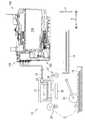
筐体14の内部には、図1及び図2に示されるように、給送トレイ15と、給送ローラ23と、搬送ローラ25と、複数のノズル29を有するヘッド21と、ヘッド21に対面するプラテン26と、排出ローラ27と、排出トレイ16と、カートリッジ200が着脱される装着ケース150と、ヘッド21及び装着ケース150に装着されたカートリッジ200を連通させるチューブ32とが位置している。 Inside the
プリンタ10は、給送ローラ23及び搬送ローラ25を駆動させて、給送トレイ15に支持されたシートをプラテン26の位置まで搬送する。次に、プリンタ10は、装着ケース150に装着されたカートリッジ200からチューブ32を通じて供給されるインクを、ヘッド21にノズル29を通じて吐出させる。これにより、プラテン26に支持されたシートにインクが着弾して、シート上に画像が記録される。そして、プリンタ10は、排出ローラ27を駆動させて、画像が記録されたシートを排出トレイ16に排出する。 The
より詳細には、ヘッド21は、搬送ローラ25によるシートの搬送向きと交差する主走査方向に往復移動するキャリッジに搭載されていてもよい。そして、プリンタ10は、主走査方向の一方から他方へキャリッジを移動させる過程で、ヘッド21にノズル29を通じてインクを吐出させてもよい。これにより、ヘッド21に対面するシートの一部の領域(以下、「1パス」と表記する。)に画像が記録される。次に、プリンタ10は、次に画像が記録されるべき領域がヘッド21に対面するように、搬送ローラ25にシートを搬送させてもよい。そして、これらの処理を交互に繰り返し実行させることによって、1枚のシートに画像が記録される。 More specifically, the
[カバー87]
図1に示されるように、筐体14の前面14Aで且つ左右方向9の右端部には、開口85が形成されている。筐体14は、さらにカバー87を備える。カバー87は、開口85を閉塞させる被覆位置(図1(A)に示される位置)と、開口85を開放する露出位置(図1(B)に示される位置)との間を回動可能である。カバー87は、例えば、上下方向7における筐体14の下端近傍において、左右方向9に沿う回動軸線周りに回動可能に、筐体14によって支持されている。そして、開口85の奥に広がる筐体14内部の収容空間86には、装着ケース150が位置している。[Cover 87]
As shown in FIG. 1, an
[カバーセンサ88]
プリンタ10は、カバーセンサ88(図6参照)を有する。カバーセンサ88は、例えば、カバー87が接離するスイッチ等の機械式センサであってもよいし、カバー87の位置によって光が遮断或いは透過される光学式センサであってもよい。カバーセンサ88は、カバー87の位置に応じた信号をコントローラ130に出力する。より詳細には、カバーセンサ88は、カバー87が被覆位置に位置していることに応じて、ローレベル信号をコントローラ130へ出力する。一方、カバーセンサ88は、カバー87が被覆位置と異なる位置に位置していることに応じて、ローレベル信号より信号強度の高いハイレベル信号をコントローラ130へ出力する。換言すれば、カバーセンサ88は、カバー87が露出位置に位置していることに応じて、ハイレベル信号をコントローラ130へ出力する。ハイレベル信号は第3信号の一例であり、ローレベル信号は第4信号の一例である。[Cover sensor 88]
The
[装着ケース150]
装着ケース150は、図3に示されるように、接点152と、ロッド153と、装着センサ154と、液面センサ155と、ロックピン156とを備えている。装着ケース150には、ブラック、シアン、マゼンタ、イエローの各色に対応する4つのカートリッジ200が収容可能である。すなわち、装着ケース150は、接点152、ロッド153、装着センサ154、液面センサ155は、4つのカートリッジ200それぞれに対応して、4つずつ備えている。なお、装着ケース150に収容可能なカートリッジ200の数は、4つに限定されず、1つでも良いし、5つ以上でも良い。[Mounting case 150]
As shown in FIG. 3, the mounting
装着ケース150は、装着されたカートリッジ200を収容する内部空間を有する箱形状である。装着ケース150の内部空間は、上端を画定する天壁と、下端を画定する底壁と、前後方向8の後端を画定する奥壁と、左右方向9の両端を画定する一対の側壁とで画定される。一方、装着ケース150の奥壁と対面する位置は、開口85となっている。すなわち、開口85は、カバー87を露出位置に配置したときに、装着ケース150の内部空間を、プリンタ10の外部に露出させる。 The mounting
そして、カートリッジ200は、筐体14の開口85を通じて、装着ケース150に挿入され、装着ケース150から抜かれる。より詳細には、カートリッジ200は、開口85を前後方向8の後ろ向きに通過して、装着ケース150に装着される。装着ケース150から抜かれるカートリッジ200は、開口85を前後方向8の前向きに通過する。 Then, the
[接点152]
接点152は、装着ケース150の天壁に位置している。接点152は、天壁から装着ケース150の内部空間へ向けて下方に突出している。接点152は、装着ケース150にカートリッジ200が装着された状態において、カートリッジ200の後述する電極248に接する位置に位置している。接点152は、導電性を有しており、さらに上下方向7に沿って弾性的に変形可能である。接点152は、コントローラ130に電気的に接続されている。[Contact 152]
The
[ロッド153]
ロッド153は、装着ケース150の奥壁から前方へ突出している。ロッド153は、装着ケース150の奥壁において、後述するジョイント180より上方に位置している。ロッド153は、カートリッジ200が装着ケース150に装着される過程において、カートリッジ200の後述する大気連通口221を通じて大気バルブ室214に進入する。ロッド153が大気バルブ室214に進入すると、後述する大気バルブ室214を大気に連通される。[Rod 153]
The
[装着センサ154]
装着センサ154は、装着ケース150の天壁に位置している。装着センサ154は、カートリッジ200が装着ケース150に装着されているか否かを検出するためのセンサである。装着センサ154は、左右方向9に離間した発光部及び受光部を備える。装着ケース150にカートリッジ200が装着された状態において、カートリッジ200の後述する遮光リブ245は、装着センサ154の発光部及び受光部の間に位置する。換言すれば、装着センサ154の発光部及び受光部は、装着ケース150に装着されたカートリッジ200の遮光リブ245を挟んで、互いに対向した状態で位置している。[Mounting sensor 154]
The mounting
装着センサ154は、発光部から左右方向9に沿って照射された光が受光部で受光されたか否かに応じて、異なる信号(図中では、「装着信号」と表記する。)を出力する。装着センサ154は、例えば、受光部で受光された光の受光強度が閾値強度未満であることに応じて、ローレベル信号をコントローラ130へ出力する。一方、装着センサ154は、受光部で受光された光の受光強度が閾値強度以上であることに応じて、ローレベル信号より信号強度の高いハイレベル信号をコントローラ130へ出力する。ハイレベル信号は第1信号の一例であり、ローレベル信号は第2信号の一例である。 The mounting
[液面センサ155]
液面センサ155は、後述するアクチュエータ190の被検出部194が検出位置に位置しているか否かを検出するためのセンサである。液面センサ155は、左右方向9に離間した発光部及び受光部を備える。換言すれば、液面センサ155の発光部及び受光部は、検出位置に位置した被検出部194を挟んで、互いに対向した状態で位置している。液面センサ155は、発光部から出力された光が受光部で受光されたか否かに応じて異なる信号(図中では、「液面信号」と表記する。)を出力する。[Liquid level sensor 155]
The
[ロックピン156]
ロックピン156は、装着ケース150の内部空間の上端で且つ開口85付近において、左右方向9に沿って延びる棒状の部材である。ロックピン156の左右方向9の両端は、装着ケース150の一対の側壁に固定されている。ロックピン156は、4つのカートリッジ200が収納可能な4つの空間に亘って左右方向9に延びている。ロックピン156は、装着ケース150に装着されたカートリッジ200を、図5に示される装着位置に保持するためのものである。カートリッジ200は、装着ケース150に装着された状態で、ロックピン156に係合される。[Lock pin 156]
The
[タンク160]
プリンタ10は、4つのカートリッジ200それぞれに対応して、4つのタンク160を備える。タンク160は、装着ケース150の奥壁よりさらに後方に位置している。タンク160は、図3に示されるように、上壁161と、前壁162と、下壁163と、後壁164と、不図示の一対の側壁とで構成されている。なお、前壁162は、各々が前後方向8にずれた複数の壁によって構成される。タンク160の内部は、液室171が形成されている。液室171は、第2液室の一例である。[Tank 160]
The
タンク160を構成する壁のうち、少なくとも液面センサ155に対面する壁は、透光性を有している。これにより、液面センサ155が出力した光は、液面センサ155に対面する壁を透過することができる。後壁164の少なくとも一部は、上壁161、下壁163、及び側壁の端面に溶着されるフィルムでもよい。また、タンク160の側壁は、装着ケース150と共通でもよいし、装着ケース150とは独立していてもよい。さらに、左右方向9に隣接するタンク160の間は、不図示の隔壁によって仕切られている。4つのタンク160の構成は、概ね共通する。 Of the walls constituting the
液室171は、流出口174を通じて不図示のインク流路に連通されている。流出口174の下端は、液室171の下端を画定する下壁163によって画定されている。流出口174は、ジョイント180(より詳細には、貫通孔184の下端)より上下方向7の下方に位置している。流出口174に連通された不図示のインク流路は、チューブ32に連通されている。これにより、液室171は、流出口174からインク流路及びチューブ32を通じて、ヘッド21と連通する。つまり、液室171に貯留されたインクは、流出口174からインク流路及びチューブ32を通じて、ヘッド21へ供給される。流出口174に連通されたインク流路及びチューブ32は、一端(流出口174)が液室171に連通され、且つ他端33(図2参照)がヘッド21に連通された第4流路の一例である。 The
液室171は、大気連通室175を通じて大気に連通されている。より詳細には、大気連通室175は、前壁162を貫通する貫通孔176を通じて液室171に連通されている。また、大気連通室175は、大気連通ポート177及び大気連通ポート177に接続された不図示のチューブを通じて、プリンタ10の外部に連通されている。すなわち、大気連通室175は、一端(貫通孔176)が液室171に連通され、且つ他端(大気連通ポート177)がプリンタ10の外部に連通された第5流路の一例である。なお、大気連通室175は、大気連通ポート177及び不図示のチューブを通じて、大気に連通している。 The
[ジョイント180]
ジョイント180は、図3に示されるように、ニードル181と、ガイド182とを備えている。ニードル181は、内部に流路が形成された管である。ニードル181は、液室171を画定する前壁162から前方へ突出している。ニードル181の突出先端には、開口183が形成されている。また、ニードル181の内部空間は、前壁162を貫通する貫通孔184を通じて液室171に連通されている。ニードル181は、一端(開口183)がタンク160の外部に連通され、且つ他端(貫通孔184)が液室171に連通された第3流路の一例である。ガイド182は、ニードル181の周囲に配置された円筒形状の部材である。ガイド182は、前壁162から前方に突出して、突出端が開口している。[Joint 180]
The joint 180 includes a
ニードル181の内部空間には、バルブ185と、コイルバネ186とが位置している。バルブ185は、ニードル181の内部空間において、閉塞位置と開放位置との間を、前後方向8に沿って移動可能である。バルブ185は、閉塞位置に位置すると開口183を閉塞する。またバルブ185は、開放位置に位置すると開口183を開放する。コイルバネ186は、バルブ185を開放位置から閉塞位置に移動させる向き、すなわち前後方向8の前向きに付勢している。 A
[アクチュエータ190]
液室171には、アクチュエータ190が位置している。アクチュエータ190は、液室171内に配置された不図示の支持部材によって、矢印198、199の向きに回動可能に支持されている。アクチュエータ190は、図3の実線で示される位置及び破線で示される位置の間を回動することができる。さらに、アクチュエータ190は、不図示のストッパ(例えば、液室171の内壁)によって、実線の位置より矢印198の向きへの回動が規制される。アクチュエータ190は、フロート191と、軸192と、アーム193と、被検出部194とを備える。[Actuator 190]
The
フロート191は、液室171に貯留されるインクより比重が小さい材料で形成されている。軸192は、フロート191の右面及び左面から左右方向9に突出している。軸192は、支持部材に形成された不図示の孔に挿入されている。これにより、アクチュエータ190は、軸192を中心として回動可能に支持部材によって支持される。アーム193は、フロート191から略上方へ延びている。被検出部194は、アーム193の突出先端部に位置している。被検出部194は、上下方向7及び前後方向8に延びる板状の部材である。被検出部194は、液面センサ155の発光部から出力された光を遮光する材料又は色で形成されている。 The
液室171内のインクの液面が境界位置P以上のとき、浮力によって矢印198の向きに回動されたアクチュエータ190は、ストッパによって図3の実線で示される検出位置に保持される。一方、インクの液面が境界位置P未満のとき、アクチュエータ190は、液面の降下に追従して矢印199の向きに回動される。これにより、被検出部194は、検出位置から外れた位置に移動する。すなわち、被検出部194は、液室171に貯留されたインクの量に対応する位置に移動する。 When the liquid level of the ink in the
境界位置Pは、上下方向7において、ニードル181の軸中心と同じ高さであり、且つ後述するインク供給口234の中心と同じ高さである。しかしながら、境界位置Pは、上下方向7における流出口174より上方の位置であれば、前述の位置に限定されない。他の例として、境界位置Pは、ニードル181の内部空間の上端や下端の高さでもよいし、インク供給口234の上端や下端の高さでもよい。 The boundary position P is at the same height as the axial center of the
液室171に貯留されたインクの液面が境界位置P以上のとき、液面センサ155の発光部から出力された光が被検出部194で遮られる。これにより、液面センサ155は、発光部からの光が受光部に到達しないので、ローレベル信号をコントローラ130へ出力する。一方、液室171に貯留されたインクの液面が境界位置P未満のとき、液面センサ155は、発光部から出力された光が受光部に到達するので、ハイレベル信号をコントローラ130へ出力する。すなわち、コントローラ130は、液室171内のインクの液面が境界位置P以上か否かを、液面センサ155から出力される信号によって検出することができる。 When the liquid level of the ink stored in the
[カートリッジ200]
カートリッジ200は、液体の一例であるインクを内部に貯留可能な液室210(図2参照)を有する容器である。液室210は、例えば、樹脂製の壁によって画定されている。カートリッジ200は、図4(A)に示されるように、上下方向7及び前後方向8それぞれに沿った寸法が、左右方向9に沿った寸法よりも大きい扁平形状である。なお、異なる色のインクが貯留されるカートリッジ200の外形形状は、同一でもよいし、異なっていてもよい。カートリッジ200を構成する壁のうちの少なくとも一部は、透光性を有している。これにより、ユーザは、カートリッジ200の液室210に貯留されたインクの液面をカートリッジ200の外部から視認することができる。[Cartridge 200]
The
カートリッジ200は、筐体201と、供給管230とを備える。筐体201は、後壁202と、前壁203と、上壁204と、下壁205と、一対の側壁206、207とで構成されている。なお、後壁202は、各々が前後方向8にずれた複数の壁によって構成されている。また、上壁204は、各々が上下方向7にずれた複数の壁によって構成されている。さらに、下壁205は、各々が上下方向7にずれた複数の壁によって構成されている。 The
カートリッジ200の内部空間には、図4(B)に示されるように、液室210、インクバルブ室213、及び大気バルブ室214が形成されている。液室210は、上部液室211と、下部液室212とを有する。上部液室211、下部液室212、及び大気バルブ室214は、筐体201の内部空間である。一方、インクバルブ室213は、供給管230の内部空間である。液室210は、インクを貯留する。大気バルブ室214は、液室210とカートリッジ200の外部とを連通させる。液室210は、第1液室の一例である。 As shown in FIG. 4B, a
液室210の上部液室211及び下部液室212は、筐体201の内部空間を仕切る隔壁215によって、上下方向7に隔てられている。そして、上部液室211及び下部液室212は、隔壁215に形成された貫通孔216によって連通されている。また、上部液室211及び大気バルブ室214は、筐体201の内部空間を仕切る隔壁217によって、上下方向7に隔てられている。そして、上部液室211及び大気バルブ室214は、隔壁217に形成された貫通孔218によって連通されている。さらに、インクバルブ室213は、貫通孔219を通じて下部液室212の下端に連通されている。 The upper
大気バルブ室214は、カートリッジ200の上部において、後壁202に形成された大気連通口221を通じてカートリッジ200の外部に連通されている。すなわち、大気バルブ室214は、一端(貫通孔218)が液室210(より詳細には、上部液室211)に連通され、且つ他端(大気連通口221)がカートリッジ200の外部に連通された第2流路の一例である。なお、大気バルブ室214は、大気連通口221を通じて、大気に連通している。また、大気バルブ室214には、バルブ222と、コイルバネ223とが位置している。バルブ222は、閉塞位置と開放位置との間を、前後方向8に沿って移動可能である。バルブ222は、閉塞位置に位置すると、大気連通口221を閉塞する。また、バルブ222は、開放位置に位置すると大気連通口221を開放する。コイルバネ223は、バルブ222を開放位置から閉塞位置に移動させる向き、すなわち前後方向8の後ろ向きに付勢している。 The
カートリッジ200が装着ケース150に装着される過程において、ロッド153が大気連通口221を通じて大気バルブ室214内に進入する。大気バルブ室214内に進入したロッド153は、閉塞位置のバルブ222をコイルバネ223の付勢力に抗して前向きに移動させる。そして、バルブ222が開放位置に移動することによって、上部液室211が大気に連通される。なお、大気連通口221を開放するための構成は、前述の例に限定されない。他の例として、大気連通口221を封止するフィルムをロッド153が突き破る構成でもよい。 In the process of mounting the
供給管230は、筐体201の下部において、後壁202から後方に突出している。供給管230は、その突出端(すなわち、後端)が開口されている。すなわち、インクバルブ室213は、貫通孔219を通じて連通された液室210と、カートリッジ200の外部とを連通させる。インクバルブ室213は、一端(貫通孔219)が液室210(より詳細には下部液室212)と連通され、且つ他端(後述するインク供給口234)がカートリッジ200の外部と連通された第1流路の一例である。また、インクバルブ室213には、パッキン231と、バルブ232と、コイルバネ233とが位置している。 The
パッキン231の中央には、前後方向8に貫通したインク供給口234が形成されている。インク供給口234の内径は、ニードル181の外径より僅かに小さい。バルブ232は、閉塞位置と開放位置との間を、前後方向8に沿って移動可能である。バルブ232は、閉塞位置に位置すると、パッキン231と当接してインク供給口234を閉塞する。また、バルブ232は、開放位置に位置すると、パッキン231から離間してインク供給口234を開放する。コイルバネ233は、バルブ232を開放位置から閉塞位置に移動させる向き、すなわち前後方向8の後ろ向きに付勢している。また、コイルバネ233の付勢力は、コイルバネ186より大きい。 An
カートリッジ200が装着ケース150に装着される過程において、供給管230がガイド182内に進入し、やがてニードル181がインク供給口234を通じてインクバルブ室213に進入する。このとき、ニードル181は、パッキン231を弾性変形させつつ、インク供給口234を画定する内周面に液密に接触する。カートリッジ200が装着ケース150へさらに挿入されると、ニードル181は、バルブ232をコイルバネ233の付勢力に抗して前向きに移動させる。また、バルブ232は、ニードル181の開口183から突出するバルブ185を、コイルバネ186の付勢力に抗して後ろ向きに移動させる。 In the process of mounting the
これにより、図5に示されるように、インク供給口234及び開口183が開放されて、供給管230のインクバルブ室213と、ニードル181の内部空間とが連通される。すなわち、装着ケース150にカートリッジ200が装着された状態において、インクバルブ室213及びニードル181の内部空間は、カートリッジ200の液室210とタンク160の液室171とを連通させる流路を構成する。 As a result, as shown in FIG. 5, the
また、装着ケース150にカートリッジ200が装着された状態において、液室210の一部と、液室171の一部とは、水平方向から見て互いに重なる。その結果、液室210に貯留されたインクは、接続された供給管230及びジョイント180を通じて、水頭差によってタンク160の液室171に移動する。 Further, in a state where the
上壁204には、突起241が形成されている。突起241は、上壁204の外面から上方に突出し且つ前後方向8に沿って延びている。突起241は、ロック面242と、傾斜面243とを有する。ロック面242及び傾斜面243は、上壁204より上方に位置している。ロック面242は、前後方向8の前方を向き且つ上下方向7及び左右方向9に延びている(すなわち、上壁204と概ね直交する)。傾斜面243は、上下方向7の上方及び前後方向8の後方を向くように、上壁204に対して傾斜している。 A
ロック面242は、装着ケース150にカートリッジ200が装着された状態において、ロックピン156に当接される面である。傾斜面243は、カートリッジ200が装着ケース150に装着される過程において、ロックピン156をロック面242と当接する位置まで案内する面である。ロック面242とロックピン156とが当接した状態では、コイルバネ186、223、233の付勢力に抗して、カートリッジ200が図5に示される装着位置に保持される。 The
ロック面242より前方において上壁204から上方へと延びるようにして、平板状の部材が形成されている。この平板状の部材の上面は、カートリッジ200を装着ケース150から抜去する際に、ユーザが操作する操作部244である。カートリッジ200が装着ケース150に装着された状態で且つカバー87が露出位置に位置しているとき、操作部244は、ユーザに操作可能となる。操作部244が下方へ押されると、カートリッジ200が回動することによって、ロック面242がロックピン156より下方へ移動する。その結果、カートリッジ200が装着ケース150から抜去することが可能となる。 A flat plate-shaped member is formed so as to extend upward from the
上壁204の外面で且つ突起241より後方には、遮光リブ245が形成されている。遮光リブ245は、上壁204の外面から上方に突出し且つ前後方向8に沿って延びている。遮光リブ245は、装着センサ154の発光部から出力される光を遮光する材料又は色で形成されている。遮光リブ245は、装着ケース150にカートリッジ200が装着された状態において、装着センサ154の発光部から受光部に至る光路上に位置する。すなわち、装着センサ154は、装着ケース150にカートリッジ200が装着されていることに応じて、ローレベル信号をコントローラ130に出力する。一方、装着センサ154は、装着ケース150にカートリッジ200が装着されていないことに応じて、ハイレベル信号をコントローラ130に出力する。すなわち、コントローラ130は、装着ケース150にカートリッジ200が装着されているか否かを、装着センサ154から出力される信号によって検出することができる。 A light-shielding
上壁204の外面で且つ前後方向8における遮光リブ245及び突起241の間には、ICチップ247が位置している。ICチップ247には、電極248が形成されている。また、ICチップ247は、不図示のメモリを備える。電極248は、ICチップ247の上記メモリと電気的に接続されている。電極248は、ICチップ247の上面において、接点152と導通可能に露出されている。すなわち、カートリッジ200が装着ケース150に装着された状態において、電極248は、接点152と電気的に導通する。コントローラ130は、接点152及び電極248を通じてICチップ247のメモリから情報を読み出し、接点152及び電極248を通じてICチップ247のメモリに情報を書き込むことができる。 The
ICチップ247のメモリは、最大インク量Vc0と、粘度ρと、後述するインク量Vc、高さHc、流路抵抗Rc、及び関数Fcとを記憶する。ICチップ247のメモリはカートリッジメモリの一例である。最大インク量Vc0は、カートリッジ200に貯留可能なインクの最大量を示す最大液体量の一例である。換言すれば、インク量Vc0は、新品のカートリッジ200に貯留されているインクの量を示す。粘度ρは、カートリッジ200に貯留されているインクの粘度を示す。以下、ICチップ247のメモリに記憶されている情報を総称して、「CTG情報」と表記することがある。また、「新品」とは、カートリッジ200から、カートリッジ200内のインクが一度も流出していない状態を示す。 The memory of the
ICチップ247のメモリの記憶領域は、例えば、第1領域と、第2領域と、第3領域とを含む。第1領域、第2領域、及び第3領域は、互いに異なるメモリ領域である。第1領域及び第3領域は、コントローラ130によって情報が上書きされない領域である。一方、第2領域は、コントローラ130によって情報が上書き可能な領域である。そして、第1領域に流路抵抗Rc及び関数Fcが記憶され、第2領域にインク量Vc及び高さHcが記憶され、第3領域に最大液体量Vc0が記憶される。 The memory storage area of the
[コントローラ130]
コントローラ130は、図6に示されるように、CPU131、ROM132、RAM133、EEPROM134、及びASIC135を備えている。ROM132には、CPU131が各種動作を制御するためのプログラムなどが格納されている。RAM133は、CPU131が上記プログラムを実行する際に用いるデータや信号等を一時的に記録する記憶領域、或いはデータ処理の作業領域として使用される。EEPROM134には、電源オフ後も保持すべき設定情報が格納される。ROM132、RAM133、及びEEPROM134は、装置メモリの一例である。[Controller 130]
As shown in FIG. 6, the
ASIC135は、給送ローラ23、搬送ローラ25、排出ローラ27、及びヘッド21を動作させるためのものである。コントローラ130は、ASIC135を通じて不図示のモータを駆動させることによって、給送ローラ23、搬送ローラ25、及び排出ローラ27を回転させる。また、コントローラ130は、ASIC135を通じてヘッド21の駆動素子に駆動信号を出力することによって、ヘッド21にノズル29を通じてインクを吐出させる。ASIC135は、ノズル29を通じて吐出すべきインクの量に応じて、複数種類の駆動信号を出力可能である。 The
また、ASIC135には、ディスプレイ17と、操作パネル22とが接続されている。ディスプレイ17は、液晶ディスプレイ、有機ELディスプレイ等であり、各種情報を表示する表示面を備える。ディスプレイ17は、報知機の一例である。但し、報知機の具体例はディスプレイ17に限定されず、スピーカ、LEDランプ、或いはこれらの組み合わせでもよい。操作パネル22は、ユーザによる操作に応じた操作信号をコントローラ130に出力する。操作パネル22は、例えば、押ボタンを有していてもよいし、ディスプレイに重畳されたタッチセンサを有していてもよい。 Further, the
さらに、ASIC135には、接点152と、カバーセンサ88と、装着センサ154と、液面センサ155とが電気的に接続されている。コントローラ130は、装着ケース150に装着されたカートリッジ200のICチップ247のメモリに、接点152を通じてアクセスする。コントローラ130は、カバー87の位置をカバーセンサ88を通じて検出する。また、コントローラ130は、カートリッジ200の挿抜を装着センサ154を通じて検出する。さらに、コントローラ130は、液室171内のインクの液面が境界位置P以上か否かを液面センサ155を通じて検出する。 Further, the
EEPROM134は、装着ケース150に装着される4つのカートリッジ200それぞれに対応付けて、換言すれば、カートリッジ200と連通されるタンク160それぞれに対応付けて、各種情報を記憶している。各種情報とは、例えば、液体量の一例であるインク量Vc、Vsと、最大インク量Vc0と、高さHc、Hsと、流路抵抗Rc、Rs、Rnと、関数Fc、Fsと、C_Emptyフラグと、S_Emptyフラグと、カウント値Nとを含む。 The
なお、最大インク量Vc0、インク量Vc、高さHc、流路抵抗Rc、及び関数Fcは、カートリッジ200が装着ケース150に装着された状態で、接点152を通じてICチップ247のメモリからコントローラ130によって読み出される情報である。また、流路抵抗Rc、Rn及び関数Fsは、EEPROM134に代えて、ROM132に記憶されていてもよい。 The maximum ink amount Vc0, ink amount Vc, height Hc, flow path resistance Rc, and function Fc are determined by the
インク量Vcは、カートリッジ200の液室210に貯留されているインクの量を示す。インク量Vsは、タンク160の液室171に貯留されているインクの量を示す。インク量Vc、Vsは、例えば、後述する式3、4によって算出される。 The ink amount Vc indicates the amount of ink stored in the
高さHcは、カートリッジ200に貯留されているインクの液面と基準位置との上下方向の高さを示す。高さHsは、タンク160に貯留されているインクの液面と基準位置との上下方向の高さを示す。一例として、基準位置は、ニードル181の内部空間の中心を通り水平方向(より詳細には、前後方向8)に沿って延びる仮想線の位置でもよい。他の例として、基準位置は、境界位置Pと同じ位置でもよい。高さHc、Hsは、例えば、式5、6によって算出される。 The height Hc indicates the height in the vertical direction between the liquid level of the ink stored in the
流路抵抗Rcは、大気バルブ室214を通過する空気が受ける抵抗の大きさを示す。より詳細には、流路抵抗Rcは、大気連通口221から貫通孔218に至る流路に位置する半透膜を空気が通過する際の抵抗を示す。流路抵抗Rsは、大気連通室175を通過する空気が受ける抵抗の大きさを示す。より詳細には、流路抵抗Rsは、大気連通ポート177から貫通孔176に至る流路に位置する半透膜を空気が通過する際の抵抗を示す。流路抵抗Raは、連通されたインクバルブ室213及びニードル181の内部空間を通過するインクが受ける抵抗の大きさを示す。より詳細には、流路抵抗Raは、インクバルブ室213を通過するインクが受ける抵抗の大きさ、ニードル181の内部空間を通過するインクが受ける抵抗の大きさの一方或いは両方を示す。 The flow path resistance Rc indicates the magnitude of the resistance received by the air passing through the
関数Fcは、インク量Vc及び高さHcの対応関係を示す情報である。カートリッジ200の液室210の水平断面積Dcが上下方向7において変化する場合、関数Fcは、インク量Vc及び高さHcを変数として、カートリッジ200の設計時に予め決定される。一方、上下方向7における水平断面積Dcが一定の場合、関数Fc=Vc/Dcとなる。第1対応情報は、関数の形式に限定されず、対応するインク量Vc及び高さHcの複数のセットを含むテーブルの形式であってもよい。 The function Fc is information indicating the correspondence between the ink amount Vc and the height Hc. When the horizontal cross-sectional area Dc of the
関数Fsは、インク量Vs及び高さHsの対応関係を示す情報である。タンク160の液室171の水平断面積Dsが上下方向7において変化する場合、関数Fsは、インク量Vs及び高さHsを変数として、タンク160の設計時に予め決定される。一方、上下方向7における水平断面積Dsが一定の場合、関数Fs=Vs/Dsとなる。なお、第2対応情報は、関数の形式に限定されず、対応するインク量Vc及び高さHcの複数のセットを含むテーブルの形式であってもよい。 The function Fs is information indicating the correspondence between the ink amount Vs and the height Hs. When the horizontal cross-sectional area Ds of the
カウント値Nは、液面センサ155から出力される信号がローレベル信号からハイレベル信号に変化した後に、ヘッド21に排出を指示したインク排出量Dh(すなわち、駆動信号で示されるインク量)に相当する値で、閾値Nthに近づく向きに更新される値である。カウント値Nは、初期値を“0”としてカウントアップされる値である。また、閾値Nthは、流出口174の上端と境界位置Pとの間の液室171の容積Vthに相当する。但し、カウント値Nは、容積Vthに相当する値を初期値として、カウントダウンされる値でもよい。この場合の閾値Nthは、0となる。The count value N is the ink discharge amount Dh (that is, the ink amount indicated by the drive signal) instructed to be discharged to the
C_Emptyフラグは、カートリッジ200がカートリッジエンプティ状態か否かを示す情報である。C_Emptyフラグには、カートリッジエンプティ状態であることに対応する値“ON”、或いはカートリッジエンプティ状態でないことに対応する値“OFF”が設定される。カートリッジエンプティ状態とは、カートリッジ200(より詳細には、液室210)にインクが実質的に貯留されていない状態である。換言すれば、カートリッジエンプティ状態とは、連通された液室210から液室171にインクが移動しない状態である。さらに換言すれば、カートリッジエンプティ状態とは、当該カートリッジ200に連通されたタンク160の液面が境界位置P未満の状態である。 The C_Empty flag is information indicating whether or not the
S_Emptyフラグは、タンク160がインクエンプティ状態か否かを示す情報である。S_Emptyフラグには、インクエンプティ状態であることに対応する値“ON”、或いはインクエンプティ状態でないことに対応する値“OFF”が設定される。インクエンプティ状態とは、例えば、タンク160(より詳細には、液室171)に貯留されたインクの液面が流出口174の上端の位置に達した状態である。換言すれば、インクエンプティ状態とは、カウント値Nが閾値Nth以上の状態である。インクエンプティ状態になった後にヘッド21によるインクの吐出を継続すると、ノズル29内がインクで満たされず、空気が混入してしまう(所謂、エアイン)可能性がある。すなわち、インクエンプティ状態は、ヘッド21を通じたインクの排出を禁止しなければならない状態である。The S_Empty flag is information indicating whether or not the
[プリンタ10の動作]
図7〜図10を参照して、本実施形態に係るプリンタ10の動作を説明する。図7〜図10に示される各処理は、コントローラ130のCPU131によって実行される。なお、以下の各処理は、ROM132に記憶されているプログラムをCPU131が読み出して実行してもよいし、コントローラ130に搭載されたハードウェア回路によって実現されてもよい。また、以下の各処理の実行順序は、本発明の要旨を変更しない範囲で、適宜変更することができる。[Operation of printer 10]
The operation of the
[画像記録処理]
コントローラ130は、プリンタ10に記録指示が入力されたことに応じて、図7に示される画像記録処理を実行する。記録指示は、画像データで示される画像をシートに記録する記録処理をプリンタ10に実行させるための排出指示の一例である。記録指示の取得先は特に限定されないが、例えば、記録指示に対応するユーザ操作を操作パネル22を通じて受け付けてもよいし、不図示の通信インタフェースを通じて外部装置から受信してもよい。[Image recording process]
The
まず、コントローラ130は、4つのS_Emptyフラグそれぞれの設定値を判断する(S11)。そして、コントローラ130は、4つのS_Emptyフラグの少なくとも1つに“ON”が設定されていると判断したことに応じて(S11:ON)、S_Empty報知画面をディスプレイ17に表示させる(S12)。S_Empty報知画面は、対応するタンク160がインクエンプティ状態になったことを、ユーザに報知するための画面である。S_Empty報知画面は、例えば、インクエンプティ状態のタンク160に貯留されているインクの色及びインク量Vc、Vsを示す情報を含んでもよい。なお、ステップS12において、コントローラ130は、4つのC_Emptyフラグの少なくとも1つに“ON”が設定されていると判断したことに応じて、C_Empty報知画面を、S_Empty報知画面と合わせてディスプレイ17に表示させてもよい。 First, the
また、コントローラ130は、“ON”が設定されたS_Emptyフラグに対応するカートリッジ200それぞれに対して、S13〜S17の処理を実行する。すなわち、S13〜S17の処理は、4つのカートリッジ200のうち、対応するS_Emptyフラグに“ON”が設定されたカートリッジ200それぞれに対して実行される。カートリッジ200毎のS13〜S17の処理は共通するので、1つのカートリッジ200に対応するS13〜S17の処理のみを説明する。 Further, the
まず、コントローラ130は、装着センサ154が出力する信号を取得する(S13)。次に、コントローラ130は、装着センサ154から取得した信号がハイレベル信号及びローレベル信号のどちらであるかを判断する(S14)。そして、コントローラ130は、装着センサ154が出力する信号が、ローレベル信号からハイレベル信号に変化し、再びハイレベル信号からローレベル信号に変化するまで(S14:No)、所定の時間間隔でS13、S14の処理を繰り返し実行する。換言すれば、コントローラ130は、カートリッジ200が装着ケース150から抜き出され、新たにカートリッジ200が装着ケース150に装着されるまで、S13、S14の処理を繰り返し実行する。 First, the
そして、コントローラ130は、装着センサ154からローレベル信号を取得し、その後に装着センサ154からハイレベル信号を取得し、さらにその後に装着センサ154からローレベル信号を取得したことに応じて(S14:Yes)、時間の計測を開始するとともに、S15〜S17の処理を実行する。まず、コントローラ130は、接点152を通じてICチップ247のメモリからCTG情報を読み出し、読み出したCTG情報をEEPROM134に記憶させる(S15)。 Then, the
また、コントローラ130は、Empty報知解除処理を実行する(S16)。Empty報知解除処理は、ディスプレイ17に表示されたC_Empty報知画面及びS_Empty報知画面を消去する処理である。Empty報知解除処理の詳細は、図10を参照して後述する Further, the
また、コントローラ130は、Empty報知解除処理と並行して残量更新処理を実行する(S17)。残量更新処理は、EEPROM134に記憶されたインク量Vc、Vs及び高さHc、Hsを更新する処理である。残量更新処理の詳細は、図8を参照して後述する。また詳細は後述するが、コントローラ130は、Empty報知解除処理及び残量更新処理と並行して、或いはEmpty報知解除処理及び残量更新処理が終了したことに応じて、S11以降の処理を再び実行する。そして、コントローラ130は、4つのS_Emptyフラグの全てに“OFF”が設定されていることに応じて(S11:OFF)、現時点で4つの液面センサ155それぞれから出力されている信号を取得する(S18)。さらにS18において、コントローラ130は、液面センサ155から取得した信号がハイレベル信号及びローレベル信号のどちらかを示す情報を、RAM133に記憶させる(S18)。 Further, the
そして、コントローラ130は、記録指示に含まれる画像データで示される画像をシートに記録する(S19)。より詳細には、コントローラ130は、給送トレイ15上のシートを給送ローラ23及び搬送ローラ25に搬送させ、ヘッド21にインクを吐出させ、画像が記録されたシートを排出ローラ27に排出トレイ16へ排出させる。すなわち、コントローラ130は、4つのS_Emptyフラグの全てに“OFF”が設定されているときにヘッド21を通じたインクの排出を許可する。一方、コントローラ130は、4つのS_Emptyフラグの少なくとも1つに“ON”が設定されているときにヘッド21を通じたインクの排出を禁止する。 Then, the
次に、コントローラ130は、記録指示に従ってシートに画像を記録したことに応じて、現時点で4つの液面センサ155それぞれから出力されている信号を取得する(S20)。さらに、S18と同様に、コントローラ130は、液面センサ155から取得した信号がハイレベル信号及びローレベル信号のどちらかを示す情報を、RAM133に記憶させる(S20)。そして、コントローラ130は、カウント処理を実行する(S21)。カウント処理は、S18、S20で液面センサ155から取得した信号に基づいて、カウント値N、C_Emptyフラグ、及びS_Emptyフラグを更新する処理である。カウント処理の詳細は、図9を参照して後述する。 Next, the
次に、コントローラ130は、記録指示で示された全ての画像をシートに記録するまで(S22:Yes)、S11〜S21の処理を繰り返し実行する。そして、コントローラ130は、記録指示で示される全ての画像をシートに記録したことに応じて(S22:No)、4つのS_Emptyフラグそれぞれの設定値及び4つのC_Emptyフラグそれぞれの設定値を判断する(S23、S24)。 Next, the
コントローラ130は、4つのS_Emptyフラグの少なくとも1つに“ON”が設定されていることに応じて(S23:ON)、S_Empty報知画面をディスプレイ17に表示させる(S25)。また、コントローラ130は、4つのS_Emptyフラグの全てに“OFF”が設定されており、且つ4つのC_Emptyフラグの少なくとも1つに“ON”が設定されていることに応じて(S23:OFF&S24:ON)、C_Empty報知画面をディスプレイ17に表示させる(S26)。S25、S26の処理は、報知機を作動させることの一例である。 The
S25で表示されるS_Empty報知画面は、S12と同様であってもよい。また、C_Empty報知画面は、”ON”が設定されたC_Emptyフラグに対応するカートリッジ200がカートリッジエンプティ状態になったことを、ユーザに報知するための画面である。C_Empty報知画面は、例えば、カートリッジエンプティ状態のカートリッジ200に貯留されているインクの色及びインク量Vc、Vsを示す情報を含んでもよい。一方、コントローラ130は、4つのS_Emptyフラグ及び4つのC_Emptyフラグの全てに“OFF”が設定されていることに応じて(S24:OFF)、S25、S26の処理を実行せずに、画像記録処理を終了する。 The S_Empty notification screen displayed in S25 may be the same as in S12. Further, the C_Empty notification screen is a screen for notifying the user that the
なお、排出指示の具体例は記録指示に限定されず、ノズル29のメンテナンスを指示するメンテナンス指示等であってもよい。コントローラ130は、例えばメンテナンス指示を取得したことに応じて、図7と同様の処理を実行する。メンテナンス指示を取得した場合の前述の処理との相違点は、以下の通りである。まず、コントローラ130は、S19において、不図示のメンテナンス機構を駆動させて、ノズル29を通じてインクを排出させる。また、コントローラ130は、カウント処理を実行した後にS22の処理を実行することなく、S23以降の処理を実行する。 The specific example of the discharge instruction is not limited to the recording instruction, and may be a maintenance instruction or the like instructing the maintenance of the
[残量更新処理]
次に図8を参照して、S17でコントローラ130が実行する残量更新処理の詳細を説明する。なお、以下の説明では、図11(A)に示されるように、タンク160内にインクが貯留されていない状態の装着ケース150に、新品(すなわち、最大インク量Vc0のインクが貯留された)カートリッジ200が装着された場合を前提とする。また、残量更新処理は、S14で新たにカートリッジ200の装着を検出した時刻tk−1から期間Δtが経過した時刻tkに実行されるものとする。すなわち、この場合の期間Δt=tk−tk−1である。[Remaining amount update process]
Next, with reference to FIG. 8, the details of the remaining amount update process executed by the
コントローラ130は、流出量Qa、Qc、インク量Vc、Vs、及び高さHc、Hsを、下記の式1〜式6を用いて算出する(S31、S32)。 The
まず、流出量Qaは、流出口174を通じて液室171から期間Δtの間に流出するインクの量を示す。S12〜S17の実行時点でヘッド21を通じてインクが排出されていないので、インク排出量Dh(tk−1)、Dh(tk)は、いずれも0となる。すなわち、コントローラ130は、式1を用いて、流出量Qa=0を算出する(S31)。First, the outflow amount Qa indicates the amount of ink that flows out from the

次に、流出量Qcは、連通されたニードル181の内部空間及びインクバルブ室213を通じて、期間Δtの間に液室210から液室171に流出するインクの量を示す。コントローラ130は、EEPROM134に記憶された高さHc、Hsを、時刻tk−1における高さHc’、Hs’として読み出す。また、コントローラ130は、粘度ρ、流路抵抗Rc、Rs、RnをEEPROM134から読み出す。そして、コントローラ130は、EEPROM134から読み出した情報と、重力加速度gと、直前に算出した流出量Qa=0とを式2に代入して、流出量Qcを算出する(S31)。Next, the outflow amount Qc indicates the amount of ink flowing out from the
流出量Qcは、式2で示されるように、高さHc’、Hs’の差(すなわち、水頭差)が大きいほど大きくなり、水頭差が小さいほど小さくなる。また、流出量Qcは、インクが実際に通過すインクバルブ室213及びニードル181の内部空間の流路抵抗Rnが大きいほど小さくなり、流路抵抗Rnが小さいほど大きくなる。 As shown in Equation 2, the outflow amount Qc increases as the difference between the heights Hc'and Hs' (that is, the head difference) increases, and decreases as the head difference decreases. Further, the outflow amount Qc becomes smaller as the flow path resistance Rn in the internal space of the
また、液室210から液室171にインクが移動すると、液室210は一時的に大気圧から減圧され、液室171は一時的に大気圧より加圧される。液室210内の圧力と大気圧との圧力差は、大気バルブ室214を通じて液室210に空気が流入することによって解消される。さらに、流出量Qa=0の場合において、液室171内の圧力と大気圧との圧力差は、大気連通室175を通じて液室171から空気が流出することによって解消される。 When the ink moves from the
そして、これらの圧力差は、液室210から液室171へのインクの移動を阻害する。すなわち、流出量Qcは、流路抵抗Rcが大きいほど小さくなり、流路抵抗Rcが小さいほど大きくなる。また、流出量Qa=0のときの流出量Qcは、流路抵抗Rsが大きいほど小さくなり、流路抵抗Rsが小さいほど大きくなる。 Then, these pressure differences hinder the movement of ink from the
次に、コントローラ130は、EEPROM134に記憶されたインク量Vcを、時刻tk−1におけるインク量Vc’として読み出す。そして、コントローラ130は、EEPROM134から読み出したインク量Vc’と、直前に算出した流出量Qcとを式3に代入して、時刻tkにおけるインク量Vcを算出する(S32)。すなわち、コントローラ130は、時刻tk−1におけるインク量Vc’から、期間Δtの間に液室210から液室171に流出したインクの流出量Qcを減じて、時刻tkにおけるインク量Vcを算出する。Next, the
またS32において、コントローラ130は、EEPROM134に記憶されたインク量Vsを、時刻tk−1におけるインク量Vs’として読み出す。そして、コントローラ130は、EEPROM134から読み出したインク量Vs’と、直前に算出した流出量Qa、Qcとを式4に代入して、時刻tkにおけるインク量Vsを算出する。すなわち、コントローラ130は、時刻tk−1におけるインク量Vs’に、期間Δtの間にタンク160から流出したインクの流出量Qaを減じ、且つ期間Δtの間に液室210から液室171に流出したインクの流出量Qcを加えて、時刻tkにおけるインク量Vsを算出する。Further, in S32, the
またS32において、コントローラ130は、EEPROM134に記憶された関数Fcを読み出す。そして、コントローラ130は、式5で示されるように直前に算出したインク量Vcを関数Fcに代入して、時刻tkにおける高さHcを特定する。さらにS32において、コントローラ130は、直前に算出したインク量Vsと容積Vthとを比較する。そして、コントローラ130は、インク量Vsが容積Vth以下(すなわち、図11(A)に示されるように、液室171の液面が境界位置P以下)だと判断したことに応じて、式6で示されるように時刻tkにおける高さHs=0と特定する。一方、コントローラ130は、インク量Vsが容積Vthより多い(すなわち、図11(B)及び図12(A)に示されるように、液室171の液面が境界位置Pより高い)と判断したことに応じて、EEPROM134から関数Fsを読み出す。そして、コントローラ130は、式6で示されるように直前に算出したインク量Vsを関数Fsに代入して、時刻tkにおける高さHsを特定する(S32)。Further, in S32, the
次に、コントローラ130は、S32で算出したインク量Vc、Vs及び高さHc、Hs(残量情報)をEEPROM134に記憶させる(S33)。より詳細には、コントローラ130は、EEPROM134に記憶されているインク量Vc、Vs及び高さHc、Hsを、直前のS32で算出したインク量Vc、Vs及び高さHc、Hsで上書きする。また、コントローラ130は、S33で算出したインク量Vc及び高さHc(残量情報)を、接点152を通じてICチップ247のメモリに記憶させる(S34)。より詳細には、コントローラ130は、ICチップ247のメモリの第2領域に記憶されているインク量Vc及び高さHcを、直前のS33で算出したインク量Vc及び高さHcで上書きする。 Next, the
なお、コントローラ130は、S34の処理に先立って、カバーセンサ88から出力されている信号を取得し、取得した信号がハイレベル信号かローレベル信号かを判断してもよい。そして、コントローラ130は、カバーセンサ88からハイレベル信号を取得したことに応じて、S35の処理を実行してもよい。一方、コントローラ130は、カバーセンサ88からローレベル信号を取得したことに応じて、S34の処理を実行せずに、S35以降の処理を実行してもよい。 The
次に、コントローラ130は、直前のS33で算出した高さHc、Hsの差と閾値高さHthとを比較する(S35)。閾値高さHthは、液室210及び液室171の間において、実質的にインクが移動しないと考えられる水頭差を示す。閾値高さHthは、例えば、0である。液室210及び液室171の間において、実質的にインクが移動しない状態を、平衡状態とする。すなわち、この平衡状態では、液室210及び液室171の水頭差が実質的に0である。Next, the
次に、コントローラ130は、高さHc、Hsの差が閾値高さHth以上だと判断したことに応じて(S35:No)、装着センサ154が出力する信号を取得する(S36)。次に、コントローラ130は、装着センサ154から取得した信号がハイレベル信号及びローレベル信号のどちらであるかを判断する(S37)。そして、コントローラ130は、装着センサ154が出力する信号がローレベル信号からハイレベル信号に変化するまで(S37:Yes)、或いは直前にS31〜S34の処理を実行してから期間Δtが経過するまで(S38:Yes)、期間Δtより短い所定の時間間隔でS36、S37の処理を繰り返し実行する。Next, the
次に、コントローラ130は、装着センサ154の出力が変化しないうちに期間Δtが経過したことに応じて(S37:No&S38:Yes)、S31以降の処理を再び実行する。換言すれば、コントローラ130は、直前にS31〜S34の処理を実行してから期間Δtが経過するまでの間、次のS31〜S34の処理の実行を待機する。S31〜S38の処理が繰り返し実行されることによって、図11(A)〜図12(A)に示されるように、高さHc、Hsの差が徐々に小さくなる。そして、コントローラ130は、高さHc、Hsの差が閾値高さHth未満だと判断したことに応じて(S35:Yes)、残量更新処理を終了する。すなわち、4つのカートリッジ200それぞれに対応する残量更新処理は、別々のタイミングで終了する可能性がある。Next, the
ここで、コントローラ130は、S38における期間Δtを可変にしてもよい。より詳細には、コントローラ130は、S38における期間Δtを、直前のS32で算出した高さHc、Hsの差が大きいほど短くし、直前のS32で算出した高さHc、Hsの差が小さいほど長くしてもよい。すなわち、コントローラ130は、繰り返し実行するS31〜S34の処理の間隔(換言すれば、インク量Vc、Vs及び高さHc、Hsの更新間隔)を、高さHc、Hsの差が大きいほど短くし、高さHc、Hsの差が小さいほど長くしてもよい。 Here, the
一方、コントローラ130は、期間Δtが経過する前に装着センサ154の出力がローレベル信号からハイレベル信号に変化したと判断したことに応じて(S38:No&S37:Yes)、S31〜S38の処理に代えて、S39〜S41の処理を実行する。装着センサ154の出力がローレベル信号からハイレベル信号に変化するのは、装着ケース150からカートリッジ200が抜かれたことに対応する。すなわち、S31〜S34の処理は、装着ケース150にカートリッジ200が装着されている間に繰り返し実行され、装着ケース150からカートリッジ200が抜かれたことに応じて停止される。 On the other hand, the
そして、コントローラ130は、装着センサ154の出力が再びハイレベル信号からローレベル信号に変化するまで(S40:No)、装着センサ154が出力する信号を所定の時間間隔で繰り返し取得する(S39)。そして、コントローラ130は、装着センサ154の出力がハイレベル信号からローレベル信号に変化したことに応じて(S40:Yes)、S41〜S41の処理を実行すると共に、再びS31以降の処理を実行する。S36、S37、S39、S40,S41の処理は、図7のS13、S14、S15の処理に対応する。 Then, the
一例として、コントローラ130は、S17で開始した残量更新処理が終了したことに応じて、S11以降の処理を実行してもよい。この場合は、図12(A)に示されるように、液室210及び液室171の液面が揃った状態で、ヘッド21を通じたインクの排出が開始される。他の例として、コントローラ130は、S17で開始した残量更新処理と並行して、S11以降の処理を実行してもよい。この場合は、図11(B)に示されるように、カートリッジ200及びタンク160の間に水頭差が生じた状態で、ヘッド21を通じたインクの排出が開始される。 As an example, the
[カウント処理]
次に図9を参照して、S21でコントローラ130が実行するカウント処理の詳細を説明する。なお、コントローラ130は、4つのカートリッジ200のそれぞれに対して、カウント処理を独立して実行する。カートリッジ200毎のカウント処理は共通するので、1つのカートリッジ200に対応するカウント処理のみを説明する。[Count processing]
Next, with reference to FIG. 9, the details of the counting process executed by the
まず、コントローラ130は、S18、S20でRAM133に記憶させた液面センサ155の信号を示す情報を比較する(S51)。すなわち、コントローラ130は、カウント処理(S21)を実行する直前のS19の処理を実行する前と後とで、4つの液面センサ155それぞれの信号が変化したか否かを判断する。 First, the
コントローラ130は、S18、S20でRAM133に記憶させた情報が共にローレベル信号を示す(すなわち、S19の処理の前後で液面センサ155の出力が変化していない)ことに応じて(S51:L→L)、残量更新処理を実行する(S52)。一方、S17で残量更新処理が開始され且つ平衡状態になる前にS19の処理が実行された場合は、S17で開始された残量更新処理が継続して実行されているので、S52で改めて残量更新処理を開始する必要がない。S52における残量更新処理は、流出量Qa≠0である点で前述の説明と相違する。以下、前述の説明との共通点の詳細な説明を省略し、相違点を中心に説明する。 The
まず、コントローラ130は、S19の開始時刻tk−1から終了時刻tkまでのインク排出量Dhを式1に代入して、流出量Qaを算出する(S32)。この場合の期間Δtは、1枚のシートに画像を記録するのに要する期間に相当する。また、この場合のインク排出量Dhは、1枚のシートに吐出されるべきインクの総排出量に相当する。すなわち、コントローラ130は、1枚のシートの画像記録を実行する度に、S32〜S35の処理を実行すればよい。但し、期間Δt及びインク排出量Dhの具体例は、これらに限定されない。First, the
他の例として、期間Δtは、1パス分の画像の記録を実行するのに要する期間に相当する。この場合において、時刻tk−1は、1パス分の画像の記録が開始される時刻である。また、時刻tkは、1パス分の画像の記録が終了した時刻である。また、インク排出量Dh(tk−1)は、S19の開始から時刻tk−1までに排出を指示したインク量に相当する。さらに、インク排出量Dh(tk)は、S19の開始から時刻tkまでに排出を指示したインク量に相当する。すなわち、コントローラ130は、1パス分の画像の記録が終了する度に、S32〜S35の処理を実行してもよい。さらに他の例として、コントローラ130は、画像記録の区切りとは関係のない任意のタイミングで、S32〜S35の処理を実行してもよい。As another example, the period Δt corresponds to the period required to record one pass of an image. In this case, the time tk-1 is the time when the recording of the image for one pass is started. In addition, time tk is the time at which the first pass content of the image recording has been completed. Further, the ink discharge amount Dh (tk-1 ) corresponds to the amount of ink instructed to discharge from the start of S19 to the time tk-1. Further, the ink discharge amount Dh(t k) is equivalent to the amount of ink has instructed the discharge by timet k from the start of the S19. That is, the
また、コントローラ130は、EEPROM134に記憶された高さHc’、Hs’、粘度ρ、及び流路抵抗Rc、Rs、Rnと、直前に算出した流出量Qaとを式2に代入して、流出量Qcを算出する(S32)。 Further, the
平衡状態の液室210、171は、共に大気圧に維持されている。この状態からヘッド21を通じてインクが排出されると、流出口174を通じて液室171からインクが流出する。さらに、ニードル181の内部空間及びインクバルブ室213を通じて液室210から液室171にインクが移動する。そして、流出量Qaが大きくなると液室210、171の水頭差が大きくなるので、流出量Qcは、流出量Qaが大きいほど大きくなる。 The
また、液室171は、ヘッド21を通じてインクが排出されることによって一時的に大気圧から減圧される。そして、液室171内の圧力と大気圧との圧力差は、液室210から液室171にインクが移動し、且つ大気連通室175を通じて液室171に空気が流入することによって解消される。そして、大気連通室175を通じて液室171に流入する空気の量は、流路抵抗Rsが大きいほど少なくなり、流路抵抗Rsが小さいほど大きくなる。そうすると、流出量Qa>0のときの流出量Qcは、液室171内を大気圧に戻すために、流路抵抗Rsが大きいほど大きくなり、流路抵抗Rsが小さいほど小さくなる。 Further, the
また図9に戻って、コントローラ130は、S18でRAM133に記憶させた情報がローレベル信号を示し、S20でRAM133に記憶させた情報がハイレベル信号を示す(すなわち、S19の処理の前後で液面センサ155の出力が変化した)ことに応じて(S51:L→H)、C_Emptyフラグに“ON”を代入する(S53)。液面センサ155の出力がローレベル信号からハイレベル信号に変化するのは、図12(B)に示されるように、S19の処理中に液室171の液面が境界位置Pに達したことに対応する。そして、これ以降は、カートリッジ200とタンク160との間でインクが移動しない。 Further, returning to FIG. 9, in the
また、コントローラ130は、EEPROM134に記憶されたインク量Vcを、予め定められた所定値(=0)で上書きする(S54)。同様に、コントローラ130は、EEPROM134に記憶されたインク量Vsを、予め定められた所定値(=容積Vth−インク排出量Dh)で上書きする(S54)。残量更新処理で算出されるインク量Vc、Vsは誤差を含むので、S32〜S35の処理の繰り返し回数が増えるほど、インク量Vc、Vsに累積される誤差が大きくなる。そこで、コントローラ130は、液面センサ155の出力がローレベル信号からハイレベル信号に変化したタイミングで、インク量Vc、Vsに予め定められた値を代入して、累積した誤差をリセットする。Further, the
なお前述したように、インク排出量Dhは、直前のS19で1枚のシートに吐出されるインク量に相当する。一方、液面センサ155の出力が変化するのは、S19の処理の途中である。すなわち、S54で上書きされたインク量Vsは、液面センサ155の出力が変化した瞬間にタンク160に貯留されているインクの量とは僅かにズレを生じている。しかしながら、このズレは僅かなので、S54で上書きしたインク量Vsを、液面センサ155の出力が変化した時点のインク量Vsとして扱うものとする。 As described above, the ink discharge amount Dh corresponds to the amount of ink discharged to one sheet in S19 immediately before. On the other hand, the output of the
また、コントローラ130は、EEPROM134に記憶されたカウント値Nに、インク排出量Dhを代入する(S55)。すなわち、コントローラ130は、直前のS19で排出を指示したインク量に相当する値で、カウント値Nをカウントアップする。換言すれば、コントローラ130は、液面センサ155の出力がローレベル信号からハイレベル信号に変化したことに応じて、カウント値Nの更新を開始する。 Further, the
次に、コントローラ130は、S55で更新したカウント値Nと、閾値Nthとを比較する(S56)。そして、コントローラ130は、S55で更新したカウント値Nが閾値Nth未満だと判断したことに応じて(S56:No)、S57の処理を実行せずに、カウント処理を終了する。一方、コントローラ130は、S55で更新したカウント値Nが閾値Nth以上だと判断したことに応じて(S56:Yes)、S_Emptyフラグに“ON”を代入する(S57)。そして、コントローラ130は、S_Emptyフラグに“ON”が設定されていることに応じてヘッド21を通じたインクの排出を禁止して、カウント処理を終了する。Next, the
また、コントローラ130は、S18、S20でRAM133に記憶させた情報が共にハイレベル信号を示すことに応じて(S51:H→H)、EEPROM134に記憶されているカウント値Nを読み出す。そして、コントローラ130は、読み出したカウント値Nにインク排出量Dhを加算して、再びEEPROM134に記憶させる(S58)。次に、コントローラ130は、S58で更新したカウント値Nを用いて、前述したS56以降の処理を実行する。 Further, the
すなわち、コントローラ130は、ヘッド21を通じてインクを排出させる度に、カートリッジ200毎にカウント処理を実行する。例えば、1つのカートリッジ200を対象として見ると、装着ケース150に装着されてからしばらくの間は残量更新処理が実行され(S51:L→L)、液面センサ155の出力が変化したタイミングでS53〜S57の処理が1回だけ実行され(S51:L→H)、その後はタンク160内のインクがなくなるまでS58、S56〜S57の処理が実行されることになる(S51:H→H)。 That is, the
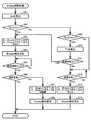
[Empty解除処理]
次に図7、図10を参照して、S16でコントローラ130が実行するEmpty解除処理の詳細を説明する。なお、コントローラ130は、4つのカートリッジ200のそれぞれに対して、S13〜S17の処理を、独立して実行する。カートリッジ200毎のEmpty解除処理は共通するので、1つのカートリッジ200に対応するEmpty解除処理のみを説明する。[Empty release process]
Next, with reference to FIGS. 7 and 10, details of the Empty release process executed by the
カウント処理において、コントローラ130は、S55で更新したカウント値Nが閾値Nth以上だと判断したことに応じて(S56:Yes)、S_Emptyフラグに“ON”を代入し(S57)、ヘッド21を通じたインクの排出を禁止する。画像記録処理において、コントローラ130は、S_Emptyフラグに“ON”が設定されていると判断したことに応じて(S11:ON)、S_Empty報知画面をディスプレイ17に表示させる(S12)。In the counting process, the
前述された状態(つまり、コントローラ130がヘッド21を通じたインクの排出を禁止し且つS_Empty報知画面をディスプレイ17に表示させている状態)において、図13(A)に示されるように、カートリッジ200は、タンク160へインクが流出しない状態、すなわち、Vc=0である。また、タンク160は、インクの液面が境界位置Pより下方であって、流出口174の上端付近の位置に達している。したがって、ユーザは、エンプティになったカートリッジ200を新品の或いは十分にインクが貯留されているカートリッジ200に交換して、ヘッド21を通じたインクの排出の禁止が解除されなければ、画像記録を行うことができない。 In the above-described state (that is, the
ユーザがカートリッジ200を交換している過程において、コントローラ130は、装着センサ154からローレベル信号を取得し、その後に装着センサ154からハイレベル信号を取得し、さらにその後に装着センサ154からローレベル信号を取得する(S14:Yes)。具体的には、カートリッジ200が装着ケース150から抜去される過程では、コントローラ130は、装着センサ154からローレベル信号を取得し、その後に装着センサ154からハイレベル信号を取得する。次に、カートリッジ200が装着ケース150に挿入される過程では、装着センサ154からハイレベル信号を取得し、その後に装着センサ154からローレベル信号を取得する。そして、コントローラ130は、接点152を通じてICチップ247のメモリからCTG情報を読み出し、読み出したCTG情報をEEPROM134に記憶させる(S15)。 In the process of the user exchanging the
Empty解除処理において、まず、コントローラ130は、S15において、接点152を通じてICチップ247のメモリから読み出してEEPROM134に記憶させたCTG情報に基づいて、流出量Qcを算出する。流出量Qcの算出は、S31における算出と同様である。カートリッジ200が交換された直後において、ヘッド21を通じたインクの排出の禁止は解除されていないので、流出量Qa=0である。また、インク量Vsが容積Vth以下なので、高さHs=0である。したがって、コントローラ130は、EEPROM134に記憶させた高さHc、粘度ρ、流路抵抗Rc、Rs、Rn、及び重力加速度gと、流出量Qa=0、高さHs=0とを式2に代入して、流出量Qcを算出する(S61)。In the Empty release process, first, in S15, the
次に、コントローラ130は、S61で算出した流出量Qcと、閾値Qth1とを比較する(S62)。閾値Qth1は、例えばヘッド21の、期間Δtにおいてヘッド21を通じたインクの排出を指示可能なインクの排出量Dhの最大値に相当する値でもよい。これにより、仮に、ヘッド21を通じたインクの排出が許可されて、期間Δtにおける排出量Dhの最大値が画像記録において指示されたとしても、液室171に対する所謂エアインが防止される。閾値Qth1は、第1閾値の一例である。Next, the
そして、コントローラ130は、S61で算出した流出量Qcが閾値Qth1以上だと判断したことに応じて(S62:Yes)、S_Emptyフラグ及びC_Emptyフラグにそれぞれ“OFF”を代入する(S63)。また、コントローラ130は、EEPROM134に記憶されているカウント値Nを、EEPROM134の別の記憶領域又はICチップ247のメモリに記憶させ、現在のカウント値Nをリセットする(S63)。すなわち、コントローラ130は、カウント値Nを”0”に更新する。そして、コントローラ130は、4つのS_Emptyフラグの全てに“OFF”が設定されていることに応じて、ヘッド21を通じたインクの排出を許可する。そして、コントローラ130は、S_Empty報知画面及びC_Empty報知画面をディスプレイ17から消去する(S64)。Then, the
続いて、コントローラ130は、装着センサ154からローレベル信号を取得し、その後に装着センサ154からハイレベル信号を取得し、さらにその後に装着センサ154からローレベル信号を取得した後(S14)に経過した時間と、時間T2とを比較する(S65)。例えば、時間T2は、図13(A)に示されるように、液室171内のインクの液面が、流出口174の上端付近の位置にある状態から、交換されたカートリッジ200からタンク160へインクが流出することによって、境界位置Pに到達するのに必要な時間である。また、例えば、時間T2は、液室210内に容積Vthに相当するインクが貯留されているときに、容積Vthに相当するすべてのインクが液室171へ流出するために要する時間であってもよい。また、例えば、時間T2は、算出された流出量Qcに基づいて、容積Vthに相当するインク量が液室171に流入するために要する時間として可変に算出されてもよい。Subsequently, the
そして、コントローラ130は、経過した時間が時間T2を超えていれば(S65:Yes)、液面センサ155の信号を取得する(S66)。図13(B)に示されるように、液室210から液室171へインクが流入して、液室171におけるインクの液面が境界位置Pに到達したとする。これにより、液面センサ155の出力が、ハイレベル信号からローレベル信号に変化する。コントローラ130は、液面センサ155からローレベル信号を取得したことに応じて(S66:Yes)、Empty解除処理を終了する。 Then, if the elapsed time exceeds the time T2 (S65: Yes), the
また、コントローラ130は、液面センサ155からローレベル信号を取得していないことに応じて(S66:No)、S_Emptyフラグ及びC_Emptyフラグにそれぞれ“ON”を代入する(S67)。例えば、カートリッジ200のICチップ247のメモリに記憶されているインク量Vcと、実際に液室210に貯留されているインク量とが合致していないことが想定される。例えば、液室210に殆どインクが貯留されていない場合には、経過した時間が時間T2を超えても、液面センサ155の出力はローレベル信号のままである。そのような場合には、S_Emptyフラグ及びC_Emptyフラグが再び“ON”にされる。また、コントローラ130は、リセットしたカウント値Nを、EEPROM134又はICチップ247のメモリに記憶させていた元のカウント値Nに更新する(S67)。そして、コントローラ130は、ディスプレイ17にS_Empty報知画面及びC_Empty報知画面を表示して(S68)、Empty解除処理を終了する。 Further, the
また、コントローラ130は、S61で算出した流出量Qcが閾値Qth1未満だと判断したことに応じて(S62:No)、S61で算出した流出量Qcと、閾値Qth2とを比較する(S69)。閾値Qth2は、閾値Qth1より小さい値である。閾値Qth2は、第2閾値の一例である。The
そして、コントローラ130は、S61で算出した流出量Qcが閾値Qth2以上だと判断したことに応じて(S69:Yes)、時間T1を算出する(S70)。閾値Qth2は、閾値Qth1より小さい値である。仮に、ヘッド21を通じたインクの排出が許可されて、期間Δtにおける排出量Dhの最大値が画像記録において指示されると、液室171に対するエアインが生じ得る。時間T1は、液室210から液室171へインクが流出してインク量Vsが増加するための時間である。時間T1は、時間T1経過後に期間Δtにおける排出量Dhの最大値が画像記録において指示されても所謂エアインが生じない時間である。したがって、時間T1は、算出された流出量Qcが大きければ短くなり、算出された流出量Qcが小さければ長くなる。Then, the
続いて、コントローラ130は、装着センサ154からローレベル信号を取得し、その後に装着センサ154からハイレベル信号を取得し、さらにその後に装着センサ154からローレベル信号を取得した後(S14)に経過した時間と、時間T1とを比較する(S71)。そして、コントローラ130は、経過した時間が時間T1に到達したと判断したことに応じて(S71:Yes)、S62〜S67の処理を実行する。 Subsequently, the
そして、コントローラ130は、S61で算出した流出量Qcが閾値Qth2未満だと判断したことに応じて(S69:No)、液面センサ155の信号を取得する(S72)。流出量Qcが閾値Qth2未満であっても、液室210から液室171へインクが流入して、液室171内のインクの液面が境界位置Pに到達すると、液面センサ155の出力が、ハイレベル信号からローレベル信号に変化する。したがって、コントローラ130は、液面センサ155からローレベル信号を受信したことに応じて(S72:Yes)、S_Emptyフラグ及びC_Emptyフラグにそれぞれ“OFF”を代入する(S73)。また、コントローラ130は、EEPROM134に記憶されているカウント値Nをリセットする(S73)。すなわち、コントローラ130は、カウント値Nを”0”に更新する。そして、コントローラ130は、4つのS_Emptyフラグの全てに“OFF”が設定されていることに応じて、ヘッド21を通じたインクの排出を許可する。そして、コントローラ130は、S_Empty報知画面及びC_Empty報知画面をディスプレイ17から消去して(S74)、Empty解除処理を終了する。Then, the
[作用効果]
上述の説明によれば、プリンタ10は、S_Empty報知画面がディスプレイ17に表示された状態において、液面センサ155の出力が変化する前に、流出量Qcと閾値Qth1との比較に基づいて、S_Empty報知画面をディスプレイ17から消去することができる。[Action effect]
According to the above description, the
また、上述の説明によれば、プリンタ10は、S_Empty報知画面をディスプレイ17から消去されてから、排出量Dhの最大量のインクが吐出される画像記録が指示されたとしても、液室171においてエアインが生じることを抑制できる。これは、閾値Qth1が、ヘッド21から期間Δtにおける排出量Dhの最大量であるためである。Further, according to the above description, even if the
また、上述の説明によれば、プリンタ10は、S_Empty報知画面がディスプレイ17に表示された状態において、カートリッジ200の交換から時間T1を待機して、液面センサ155の出力が変化する前に、S_Empty報知画面をディスプレイ17から消去することができる。プリンタ10が、S_Empty報知画面をディスプレイ17から消去する条件は、S61で算出された流出量Qcが閾値Qth1未満であり且つ閾値Qth2以上である。また、時間T1が流出量Qcに応じて算出されることにより、時間T1を短縮することができる。Further, according to the above description, the
また、上述の説明によれば、プリンタ10は、液面センサ155の出力がハイレベル信号からローレベル信号となる前に、S_Empty報知画面をディスプレイ17から消去する。その後、カートリッジ200の交換から時間T2が経過しても、液面センサ155の出力が変化しないときには、S_Empty報知画面がディスプレイ17に表示される。これにより、プリンタ10は、仮にカートリッジ200のICチップ247のメモリに書き込まれた液体量Vcが正確でなく、液室210から液室171へインクが殆ど流出しないときには、S_Empty報知画面をディスプレイ17に再表示させることができる。また、同様に、プリンタ10は、カートリッジ200の交換後に、液室210から液室171へインクが殆ど流出しないときには、EEPROM134又ICチップ247に記憶させたリセット前のカウント値Nを復帰することができる。 Further, according to the above description, the
また、上述の説明によれば、プリンタ10は、S61で算出された流出量Qcが閾値Qth2未満であるときには、液面センサ155の出力が変化したことに基づいて、S_Empty報知画面をディスプレイ17から消去することができる。Further, according to the above description, the
また、上述の説明によれば、プリンタ10は、S_Empty報知画面がディスプレイ17に表示されると共に、ヘッド21からのインクの排出が禁止されるので、液室171タンク160に対するエアインが生ずることを抑制できる。 Further, according to the above description, in the
また、上述の説明によれば、プリンタ10は、ヘッド21にインクを排出させたことに伴って液室210、171の液面の高さに差が生じたとしても、式1〜式4に従ってインク量Vc、Vsを個別に算出することができる。また、プリンタ10は、式2で高さHc、Hsを考慮して流出量Qcを算出するので、排出指示を取得した時点で既に液室210、171の液面が揃っていない場合でも、流出量Qcを適切に算出することができる。その結果、インク量Vc、Vsを適切に算出することができる。 Further, according to the above description, even if the
また、上述の説明によれば、装着ケース150にカートリッジ200が装着された時点で、液室210、171の液面の高さが異なっているとしても、液室210、171の液面が揃うまでの期間中において、プリンタ10は、式1〜式4に従って、インク量Vc、Vsを個別に算出することができる。但し、装着ケース150からカートリッジ200が抜かれるとインクの移動もなくなるので、プリンタ10は、装着センサ154からハイレベル信号が出力されたことに応じて、高さHc、Hsが閾値高さHth未満か否かに拘わらず、S32〜S35の処理を停止するのが望ましい。Further, according to the above description, even if the heights of the liquid levels of the
また、上述の説明によれば、プリンタ10は、期間Δtが経過する度にS32〜S35の処理を繰り返し実行する。その結果、液室210、171の液面が揃うまでの期間中において、プリンタ10は、インク量Vc、Vsをリアルタイムに把握することができる。なお、流出量Qcは、高さHc、Hsの差が大きいほど大きくなり、高さHc、Hsの差が小さいほど小さくなる。そこで上述の説明のように、高さHc、Hsの差に応じてS32〜S35の実行頻度を変更することによって、リアルタイムなインク量Vc、Vsの把握と、コントローラ130の処理負荷の軽減とを両立させることができる。 Further, according to the above description, the
また、上述の説明によれば、プリンタ10は、装着ケース150にカートリッジ200が装着されたタイミングで、最大インク量Vc0、粘度ρ、流路抵抗Rc、関数Fcを、ICチップ247のメモリから読み出す。そして、プリンタ10は、読み出した最大インク量Vc0、粘度ρ、流路抵抗Rc、関数Fcを用いて、流出量Qa、Qc、インク量Vc、Vs、及び高さHc、Hsを算出する。これにより、プリンタ10は、CTG情報がカートリッジ200毎に異なる場合であっても、S32、S33で適切な値を算出することができる。 Further, according to the above description, the
また、上述の説明によれば、プリンタ10は、S32で算出したインク量Vc及び高さHcをICチップ247のメモリに書き込む。これにより、装着ケース150から抜かれたカートリッジ200が他のプリンタ10に装着された場合において、当該他のプリンタ10がカートリッジ200に貯留されたインクの量を適切に把握することができる。但し、装着ケース150からカートリッジ200が抜かれるのは、カバー87が露出位置に配置されている場合だけである。そこで上述の説明のように、プリンタ10は、カバーセンサ88からハイレベル信号が出力されている場合にのみICチップ247のメモリのインク量Vc及び高さHcを更新する。これによって、ICチップ247のメモリへのアクセス回数を削減することができる。 Further, according to the above description, the
[変形例]
なお、上述の説明では、プリンタ10は、カウント値Nが閾値Nthに達したことに応じて、ヘッド21を通じたインクの排出を禁止する例を説明した。しかしながら、インクの排出を禁止するトリガはこれに限定されず、算出したインク量Vsが閾値(例えば、0)に達したことであってもよい。[Modification example]
In the above description, the
また、上述の説明では、インクを液体の一例として説明した。しかしながら、液体は、例えば、画像記録時にインクに先立って用紙などに吐出される前処理液でもよいし、ヘッド21を洗浄するための水でもよい。 Further, in the above description, ink has been described as an example of a liquid. However, the liquid may be, for example, a pretreatment liquid that is ejected onto paper or the like prior to the ink during image recording, or water for cleaning the
10・・・プリンタ
17・・・ディスプレイ
21・・・ヘッド
130・・・コントローラ
134・・・EEPROM
150・・・装着ケース
152・・・接点
154・・・装着センサ
155・・・液面センサ
160・・・タンク
171・・・液室
175・・・大気連通室
176・・・貫通孔
177・・・大気連通ポート
181・・・ニードル
183・・・開口
184,216,219・・・貫通孔
200・・・カートリッジ
210・・・液室
211・・・上部液室
212・・・下部液室
213・・・インクバルブ室
214・・・大気バルブ室
221・・・大気連通口
230・・・供給管
234・・・インク供給口
10 ...
150 ... Mounting
Claims (11)
Translated fromJapanese第2液室を有するタンクであって、
一端が外部と連通され且つ他端が上記第2液室と連通される第3流路であって、上記カートリッジが上記装着ケースに装着されたときに、上記第1液室及び上記第2液室を連通させる流路を、上記第1流路と共に構成する上記第3流路と、
上記第3流路よりも下方に位置する一端が上記第2液室と連通される第4流路と、
一端が上記第2液室に連通され且つ他端が外部と連通される第5流路と、
を有する上記タンクと、
上記第4流路の他端と連通されるヘッドと、
液面センサと、
装着センサと、
報知機と、
接点と、
コントローラと、を備える液体排出装置であって、
上記カートリッジは、上記カートリッジが上記装着ケースに装着された状態で上記接点と導通可能なカートリッジメモリを備えており、
上記コントローラは、
上記第2液室内の液面の位置が境界位置以上であることに応じて上記液面センサが出力する第1信号を、上記液面センサから受信し、
上記第2液室内の液面の位置が上記境界位置未満であることに応じて上記液面センサが出力する第2信号を、上記第1信号の受信後に、上記液面センサから受信し、
上記第2信号の受信後に、上記ヘッドを通じて液体を排出させる排出指示を受け付け、上記排出指示で排出が指示された液体の量に相当する値でカウント値を閾値に近づく向きに更新し、
上記カウント値が上記閾値に達したことに応じて、上記報知機を作動させ、
上記装着ケースに上記カートリッジが装着されていないことに応じて上記装着センサが出力する第3信号を、上記装着センサから受信し、
上記装着ケースに上記カートリッジが装着されていることに応じて上記装着センサが出力する第4信号を、上記第3信号を受信した後に、上記装着センサから受信し、
上記第3信号を受信した後に、上記第4信号を上記装着センサから受信したことに応じて、上記第1液室に貯留されている液体量Vcを上記カートリッジメモリから読み出し、
読み出された上記液体量Vcに基づいて、上記第1液室から上記第2液室へ期間Δtに流出する液体の流出量Qcを算出し、
算出された上記流出量Qcが第1閾値以上であること及び上記報知機を作動させていることに応じて、上記報知機の作動を解除する液体排出装置。A first liquid chamber in which a liquid is stored, a first flow path in which one end communicates with the first liquid chamber and the other end communicates with the outside, and one end communicates with the first liquid chamber and the other end communicates with the outside. A mounting case in which a cartridge having a second flow path communicating with the cartridge is mounted, and
A tank with a second liquid chamber
One end is a third flow path that communicates with the outside and the other end communicates with the second liquid chamber, and when the cartridge is mounted in the mounting case, the first liquid chamber and the second liquid The third flow path and the third flow path, which form the flow path for communicating the chamber together with the first flow path,
A fourth flow path in which one end located below the third flow path communicates with the second liquid chamber, and
A fifth flow path in which one end communicates with the second liquid chamber and the other end communicates with the outside.
With the above tank
A head that communicates with the other end of the fourth flow path,
Liquid level sensor and
With the mounting sensor
With an alarm
With contacts
A liquid discharge device including a controller.
The cartridge includes a cartridge memory that can conduct with the contacts in a state where the cartridge is mounted in the mounting case.
The above controller
The first signal output by the liquid level sensor according to the position of the liquid level in the second liquid chamber is equal to or higher than the boundary position is received from the liquid level sensor.
After receiving the first signal, the second signal output by the liquid level sensor according to the position of the liquid level in the second liquid chamber is less than the boundary position is received from the liquid level sensor.
After receiving the second signal, a discharge instruction for discharging the liquid is received through the head, and the count value is updated in a direction approaching the threshold value with a value corresponding to the amount of the liquid instructed to be discharged by the discharge instruction.
When the count value reaches the threshold value, the alarm is activated.
The third signal output by the mounting sensor in response to the fact that the cartridge is not mounted in the mounting case is received from the mounting sensor, and the third signal is received from the mounting sensor.
After receiving the third signal, the fourth signal output by the mounting sensor according to the mounting of the cartridge in the mounting case is received from the mounting sensor.
After receiving the third signal, the amount of liquid Vc stored in the first liquid chamber is read from the cartridge memory in response to receiving the fourth signal from the mounting sensor.
Based on the read-out liquid amount Vc, the outflow amount Qc of the liquid flowing out from the first liquid chamber to the second liquid chamber in the period Δt was calculated.
A liquid discharge device that releases the operation of the alarm according to the calculated outflow amount Qc being equal to or higher than the first threshold value and operating the alarm.
上記報知機を作動させている間であって且つ上記第3信号を受信した後に、上記第4信号を上記装着センサから受信したことに応じて、第1時間の計測を開始し、
算出した上記流出量Qcが第1閾値未満、かつ第1閾値より小さな第2閾値以上であることに応じて、計測が開始された上記第1時間が待機時間T1に到達したかを判断し、
計測された上記第1時間が上記待機時間T1に到達したと判断したことに応じて、上記報知機の作動を解除する請求項1に記載の液体排出装置。The above controller
While the alarm is operating and after receiving the third signal, the measurement for the first hour is started in response to the reception of the fourth signal from the mounting sensor.
According to the calculated outflow amount Qc being less than the first threshold value and not more than the second threshold value smaller than the first threshold value, it is determined whether the first time when the measurement is started reaches the waiting time T1.
The liquid discharge device according to claim 1, wherein the operation of the alarm is released in response to the determination that the measured first time has reached the standby time T1.
算出された上記流出量Qcに基づいて、上記第1液室から上記第2液室へ所定の液量が流出する時間に相当する上記待機時間T1を算出する請求項2に記載の液体排出装置。The above controller
The liquid discharge device according to claim 2, wherein the standby time T1 corresponding to the time when a predetermined liquid amount flows out from the first liquid chamber to the second liquid chamber is calculated based on the calculated outflow amount Qc. ..
上記報知機の作動を解除した状態において、上記装着センサから上記第3信号を受信し、
上記報知器の作動を解除した状態且つ上記第3信号を受信した後に、上記装着センサから上記第4信号を受信したことに応じて、第2時間の計測を開始し、
上記第2時間の計測を開始してから、上記第2時間が待機時間T2に到達するまでの間に、上記液面センサから出力される上記第1信号を受信したかを判断し、
上記第2時間の計測を開始してから、上記第2時間が上記待機時間T2に到達するまでの間に、上記第1信号を受信していないと判断したことに応じて、上記報知機を再作動する請求項1から4のいずれかに記載の液体排出装置。The above controller
In the state where the operation of the alarm is released, the third signal is received from the mounting sensor, and the third signal is received.
After the operation of the alarm is released and the third signal is received, the measurement for the second time is started in response to the reception of the fourth signal from the mounting sensor.
It is determined whether or not the first signal output from the liquid level sensor has been received between the start of the measurement of the second time and the time when the second time reaches the standby time T2.
In response to the determination that the first signal has not been received between the start of the measurement of the second time and the time when the second time reaches the standby time T2, the alarm is activated. The liquid discharge device according to any one of claims 1 to 4, which is restarted.
上記コントローラは、
上記報知機の作動を解除したことに応じて、上記カウント値を上記装置メモリ及び上記カートリッジメモリのいずれかに記憶させてから、上記カウント値をリセットし、
上記報知機を再作動したことに応じて、上記装置メモリ及び上記カートリッジメモリのいずれかに記憶されたカウント値を上記カウント値として設定する請求項5に記載の液体排出装置。It has more device memory and
The above controller
In response to the release of the operation of the alarm, the count value is stored in either the device memory or the cartridge memory, and then the count value is reset.
The liquid discharge device according to claim 5, wherein a count value stored in either the device memory or the cartridge memory is set as the count value in response to the restart of the alarm.
上記報知機を作動させている間に上記第2信号を受信し、
上記報知機を作動させている間であって且つ上記第2信号を受信した後に、上記第1信号を受信し且つ上記流出量Qcが第2閾値未満であることに応じて、上記報知機の作動を解除する請求項2又は3に記載の液体排出装置。The above controller
The second signal is received while the alarm is operating,
According to the fact that the first signal is received and the outflow amount Qc is less than the second threshold value while the alarm is being operated and after the second signal is received, the alarm The liquid discharge device according to claim 2 or 3, which releases the operation.
上記コントローラは、
液体を排出する排出指示を受け付け、
上記排出指示に従って上記ヘッドに液体を排出させ、
上記排出指示に示される液体の排出量Dhを算出し、
上記ヘッドを通じた液体の排出中の期間Δtの間に上記第4流路から上記ヘッドに向けて流出する液体の流出量Qaを、算出した上記排出量Dhに基づいて算出し、
上記ヘッドを通じた液体の排出中の上記期間Δtの間に上記第1液室から上記第2液室へ流出する液体の流出量Qcを、算出した上記流出量Qa、上記第2流路の流路抵抗Rc、上記第5流路の流路抵抗Rs、及び上記第1流路及び上記第3流路の双方の抵抗又は一方の抵抗である流路抵抗Rnに基づいて算出し、
上記装置メモリから上記液体量Vc、Vsを読み出し、
読み出した上記液体量Vcから上記流出量Qcを減じて、上記期間Δtが経過した後の上記液体量Vcを算出し、
読み出した上記液体量Vsから上記流出量Qaを減じ且つ上記流出量Qcを加えて、上記期間Δtが経過した後の上記液体量Vsを算出し、
算出した上記液体量Vc、Vsを上記装置メモリに記憶させる請求項1から8のいずれかに記載の液体排出装置。It further includes an apparatus memory for storing the amount of liquid Vc stored in the first liquid chamber and the amount of liquid Vs stored in the second liquid chamber.
The above controller
Accepts discharge instructions to discharge liquid,
Discharge the liquid to the head according to the discharge instruction,
Calculate the liquid discharge amount Dh indicated in the above discharge instruction, and calculate
The outflow amount Qa of the liquid flowing out from the fourth flow path toward the head during the period Δt during the discharge of the liquid through the head was calculated based on the calculated discharge amount Dh.
The outflow amount Qa of the liquid flowing out from the first liquid chamber to the second liquid chamber during the period Δt during the discharge of the liquid through the head, the calculated outflow amount Qa, and the flow of the second flow path. Calculated based on the road resistance Rc, the flow path resistance Rs of the fifth flow path, and the flow path resistance Rn which is the resistance of both the first flow path and the third flow path or one of the resistances.
Read the liquid amounts Vc and Vs from the device memory,
By subtracting the outflow amount Qc from the read-out liquid amount Vc, the liquid amount Vc after the elapse of the period Δt is calculated.
The liquid amount Vs after the period Δt has elapsed is calculated by subtracting the outflow amount Qa from the read out liquid amount Vs and adding the outflow amount Qc.
The liquid discharge device according to any one of claims 1 to 8, wherein the calculated liquid amounts Vc and Vs are stored in the device memory.
上記カートリッジが装着される装着ケースと、
第2液室を有するタンクであって、
一端が外部と連通され且つ他端が上記第2液室と連通される第3流路であって、上記カートリッジが上記装着ケースに装着されたときに、上記第1液室及び上記第2液室を連通させる流路を、上記第1流路と共に構成する上記第3流路と、
上記第3流路よりも下方に位置する一端が上記第2液室と連通される第4流路と、
一端が上記第2液室に連通され且つ他端が外部と連通される第5流路と、
を有する上記タンクと、
上記第4流路の他端と連通されるヘッドと、
液面センサと、
装着センサと、
報知機と、
接点と、
コントローラと、を備える液体排出装置であって、
上記カートリッジは、上記カートリッジが上記装着ケースに装着された状態で上記接点と導通可能なカートリッジメモリを備えており、
上記コントローラは、
上記第2液室内の液面の位置が境界位置以上であることに応じて上記液面センサが出力する第1信号を、上記液面センサから受信し、
上記第2液室内の液面の位置が上記境界位置未満であることに応じて上記液面センサが出力する第2信号を、上記第1信号の受信後に、上記液面センサから受信し、
上記第2信号の受信後に、上記ヘッドを通じて液体を排出させる排出指示を受け付け、上記排出指示で排出が指示された液体の量に相当する値でカウント値を閾値に近づく向きに更新し、
上記カウント値が上記閾値に達したことに応じて、上記報知機を作動させ、
上記装着ケースに上記カートリッジが装着されていないことに応じて上記装着センサが出力する第3信号を、上記装着センサから受信し、
上記装着ケースに上記カートリッジが装着されていることに応じて上記装着センサが出力する第4信号を、上記第3信号を受信した後に、上記装着センサから受信し、
上記第3信号を受信した後に、上記第4信号を上記装着センサから受信したことに応じて、上記第1液室に貯留されている液体量Vcを上記カートリッジメモリから読み出し、
読み出された上記液体量Vcに基づいて、上記第1液室から上記第2液室へ期間Δtに流出する液体の流出量Qcを算出し、
算出された上記流出量Qcが第1閾値以上であること及び上記報知機を作動させていることに応じて、上記報知機の作動を解除する液体排出装置。
A first liquid chamber in which a liquid is stored, a first flow path in which one end communicates with the first liquid chamber and the other end communicates with the outside, and one end communicates with the first liquid chamber and the other end communicates with the outside. A cartridge having a second flow path that communicates with
The mounting case where the above cartridge is mounted and
A tank with a second liquid chamber
One end is a third flow path that communicates with the outside and the other end communicates with the second liquid chamber, and when the cartridge is mounted in the mounting case, the first liquid chamber and the second liquid The third flow path and the third flow path, which form the flow path for communicating the chamber together with the first flow path,
A fourth flow path in which one end located below the third flow path communicates with the second liquid chamber, and
A fifth flow path in which one end communicates with the second liquid chamber and the other end communicates with the outside.
With the above tank
A head that communicates with the other end of the fourth flow path,
Liquid level sensor and
With the mounting sensor
With an alarm
With contacts
A liquid discharge device including a controller.
The cartridge includes a cartridge memory that can conduct with the contacts in a state where the cartridge is mounted in the mounting case.
The above controller
The first signal output by the liquid level sensor according to the position of the liquid level in the second liquid chamber is equal to or higher than the boundary position is received from the liquid level sensor.
After receiving the first signal, the second signal output by the liquid level sensor according to the position of the liquid level in the second liquid chamber is less than the boundary position is received from the liquid level sensor.
After receiving the second signal, a discharge instruction for discharging the liquid is received through the head, and the count value is updated in a direction approaching the threshold value with a value corresponding to the amount of the liquid instructed to be discharged by the discharge instruction.
When the count value reaches the threshold value, the alarm is activated.
The third signal output by the mounting sensor in response to the fact that the cartridge is not mounted in the mounting case is received from the mounting sensor, and the third signal is received from the mounting sensor.
After receiving the third signal, the fourth signal output by the mounting sensor according to the mounting of the cartridge in the mounting case is received from the mounting sensor.
After receiving the third signal, the amount of liquid Vc stored in the first liquid chamber is read from the cartridge memory in response to receiving the fourth signal from the mounting sensor.
Based on the read-out liquid amount Vc, the outflow amount Qc of the liquid flowing out from the first liquid chamber to the second liquid chamber in the period Δt was calculated.
A liquid discharge device that releases the operation of the alarm according to the calculated outflow amount Qc being equal to or higher than the first threshold value and operating the alarm.
Priority Applications (3)
| Application Number | Priority Date | Filing Date | Title |
|---|---|---|---|
| JP2017072943AJP6859811B2 (en) | 2017-03-31 | 2017-03-31 | Liquid drainer |
| US15/937,962US10279594B2 (en) | 2017-03-31 | 2018-03-28 | Liquid discharge apparatus |
| US16/363,274US10744783B2 (en) | 2017-03-31 | 2019-03-25 | Liquid discharge apparatus |
Applications Claiming Priority (1)
| Application Number | Priority Date | Filing Date | Title |
|---|---|---|---|
| JP2017072943AJP6859811B2 (en) | 2017-03-31 | 2017-03-31 | Liquid drainer |
Publications (2)
| Publication Number | Publication Date |
|---|---|
| JP2018171845A JP2018171845A (en) | 2018-11-08 |
| JP6859811B2true JP6859811B2 (en) | 2021-04-14 |
Family
ID=63672822
Family Applications (1)
| Application Number | Title | Priority Date | Filing Date |
|---|---|---|---|
| JP2017072943AActiveJP6859811B2 (en) | 2017-03-31 | 2017-03-31 | Liquid drainer |
Country Status (2)
| Country | Link |
|---|---|
| US (2) | US10279594B2 (en) |
| JP (1) | JP6859811B2 (en) |
Families Citing this family (24)
| Publication number | Priority date | Publication date | Assignee | Title |
|---|---|---|---|---|
| JP6859809B2 (en) | 2017-03-31 | 2021-04-14 | ブラザー工業株式会社 | Liquid drainer |
| JP6848616B2 (en)* | 2017-03-31 | 2021-03-24 | ブラザー工業株式会社 | Liquid drainer and cartridge |
| JP6996211B2 (en)* | 2017-10-10 | 2022-01-17 | ブラザー工業株式会社 | Liquid drainer |
| JP6988351B2 (en) | 2017-10-10 | 2022-01-05 | ブラザー工業株式会社 | Liquid drainer |
| JP6972881B2 (en)* | 2017-10-10 | 2021-11-24 | ブラザー工業株式会社 | Liquid drainer |
| JP6950438B2 (en)* | 2017-10-10 | 2021-10-13 | ブラザー工業株式会社 | Liquid drainer |
| JP7159702B2 (en) | 2018-08-31 | 2022-10-25 | ブラザー工業株式会社 | system |
| WO2020100279A1 (en)* | 2018-11-16 | 2020-05-22 | ブラザー工業株式会社 | System |
| CN113168446A (en) | 2018-12-03 | 2021-07-23 | 惠普发展公司,有限责任合伙企业 | Logic circuitry packaging |
| KR20210087502A (en) | 2018-12-03 | 2021-07-12 | 휴렛-팩커드 디벨롭먼트 컴퍼니, 엘.피. | logic circuit |
| US11338586B2 (en) | 2018-12-03 | 2022-05-24 | Hewlett-Packard Development Company, L.P. | Logic circuitry |
| WO2020117395A1 (en)* | 2018-12-03 | 2020-06-11 | Hewlett-Packard Development Company, L.P. | Logic circuitry package |
| US10894423B2 (en) | 2018-12-03 | 2021-01-19 | Hewlett-Packard Development Company, L.P. | Logic circuitry |
| US11366913B2 (en) | 2018-12-03 | 2022-06-21 | Hewlett-Packard Development Company, L.P. | Logic circuitry |
| CN113165391A (en) | 2018-12-03 | 2021-07-23 | 惠普发展公司,有限责任合伙企业 | Logic circuit |
| AU2018452257B2 (en) | 2018-12-03 | 2022-12-01 | Hewlett-Packard Development Company, L.P. | Logic circuitry |
| EP3687797A1 (en) | 2018-12-03 | 2020-08-05 | Hewlett-Packard Development Company, L.P. | Logic circuitry |
| PL3688636T3 (en) | 2018-12-03 | 2023-09-11 | Hewlett-Packard Development Company, L.P. | Logic circuitry |
| ES2848998T3 (en) | 2018-12-03 | 2021-08-13 | Hewlett Packard Development Co | Logic circuits |
| WO2021080607A1 (en) | 2019-10-25 | 2021-04-29 | Hewlett-Packard Development Company, L.P. | Logic circuitry package |
| WO2020117196A1 (en)* | 2018-12-03 | 2020-06-11 | Hewlett-Packard Development Company, L.P. | Logic circuitry |
| CN111421959B (en)* | 2019-01-10 | 2021-11-02 | 珠海艾派克微电子有限公司 | Ink box |
| CN110103591B (en)* | 2019-06-13 | 2020-03-27 | 杭州旗捷科技有限公司 | Automatic resetting method of consumable chip and consumable chip |
| EP4031997A1 (en) | 2020-04-30 | 2022-07-27 | Hewlett-Packard Development Company, L.P. | Logic circuitry package for print apparatus |
Family Cites Families (10)
| Publication number | Priority date | Publication date | Assignee | Title |
|---|---|---|---|---|
| JP2005096152A (en)* | 2003-09-22 | 2005-04-14 | Konica Minolta Holdings Inc | Inkjet printer |
| US20060250425A1 (en)* | 2005-05-03 | 2006-11-09 | Pitney Bowes Incorporated | Method and system for detecting low ink levels in a printing system and replacing ink cartridge without stopping printing operations |
| JP4380712B2 (en) | 2007-02-28 | 2009-12-09 | ブラザー工業株式会社 | Droplet discharge device |
| JP4434225B2 (en)* | 2007-03-29 | 2010-03-17 | ブラザー工業株式会社 | Liquid ejection device and liquid ejection device body |
| JP6083151B2 (en)* | 2012-08-24 | 2017-02-22 | ブラザー工業株式会社 | Printing fluid supply apparatus and printing fluid cartridge |
| CN203110525U (en)* | 2012-09-18 | 2013-08-07 | 珠海艾派克微电子有限公司 | Ink cartridge and ink-jet imaging device |
| JP2014200975A (en)* | 2013-04-03 | 2014-10-27 | 富士フイルム株式会社 | Liquid discharge device and method for acquiring information about liquid residual amount |
| JP2015044379A (en)* | 2013-08-29 | 2015-03-12 | キヤノン株式会社 | Liquid discharge device and control method of the same |
| EP2990208B1 (en)* | 2014-08-29 | 2018-10-03 | Brother Kogyo Kabushiki Kaisha | Liquid consuming apparatus |
| JP6497028B2 (en)* | 2014-10-29 | 2019-04-10 | ブラザー工業株式会社 | Liquid consumption device |
- 2017
- 2017-03-31JPJP2017072943Apatent/JP6859811B2/enactiveActive
- 2018
- 2018-03-28USUS15/937,962patent/US10279594B2/enactiveActive
- 2019
- 2019-03-25USUS16/363,274patent/US10744783B2/enactiveActive
Also Published As
| Publication number | Publication date |
|---|---|
| US20180281438A1 (en) | 2018-10-04 |
| US20190217628A1 (en) | 2019-07-18 |
| JP2018171845A (en) | 2018-11-08 |
| US10744783B2 (en) | 2020-08-18 |
| US10279594B2 (en) | 2019-05-07 |
Similar Documents
| Publication | Publication Date | Title |
|---|---|---|
| JP6859811B2 (en) | Liquid drainer | |
| JP6950245B2 (en) | Liquid drainer | |
| JP6859809B2 (en) | Liquid drainer | |
| JP6848616B2 (en) | Liquid drainer and cartridge | |
| JP7135383B2 (en) | Liquid discharge device and system | |
| JP6950439B2 (en) | Liquid drainer | |
| JP6939030B2 (en) | Liquid drainer | |
| JP7119451B2 (en) | Liquid discharge device and system | |
| US10717290B2 (en) | Liquid discharge device | |
| JP6874728B2 (en) | Liquid drainer | |
| JP6950440B2 (en) | Liquid drainer | |
| JP6972881B2 (en) | Liquid drainer | |
| JP6922352B2 (en) | Liquid drainer | |
| JP7077573B2 (en) | Liquid drainer | |
| JP7119450B2 (en) | Liquid discharge device and system | |
| JP7639881B2 (en) | Liquid Discharger | |
| JP2020055114A (en) | Liquid discharge device | |
| JP6879251B2 (en) | Liquid drainer | |
| JP6950438B2 (en) | Liquid drainer | |
| JP7167467B2 (en) | Liquid ejection devices, cartridges and systems | |
| JP7063129B2 (en) | Liquid drainer | |
| JP7073853B2 (en) | Liquid drainer |
Legal Events
| Date | Code | Title | Description |
|---|---|---|---|
| A621 | Written request for application examination | Free format text:JAPANESE INTERMEDIATE CODE: A621 Effective date:20200317 | |
| A977 | Report on retrieval | Free format text:JAPANESE INTERMEDIATE CODE: A971007 Effective date:20210106 | |
| TRDD | Decision of grant or rejection written | ||
| A01 | Written decision to grant a patent or to grant a registration (utility model) | Free format text:JAPANESE INTERMEDIATE CODE: A01 Effective date:20210224 | |
| A61 | First payment of annual fees (during grant procedure) | Free format text:JAPANESE INTERMEDIATE CODE: A61 Effective date:20210309 | |
| R150 | Certificate of patent or registration of utility model | Ref document number:6859811 Country of ref document:JP Free format text:JAPANESE INTERMEDIATE CODE: R150 |