JP6857980B2 - Information processing equipment, control methods and programs for information processing equipment - Google Patents
Information processing equipment, control methods and programs for information processing equipmentDownload PDFInfo
- Publication number
- JP6857980B2 JP6857980B2JP2016152286AJP2016152286AJP6857980B2JP 6857980 B2JP6857980 B2JP 6857980B2JP 2016152286 AJP2016152286 AJP 2016152286AJP 2016152286 AJP2016152286 AJP 2016152286AJP 6857980 B2JP6857980 B2JP 6857980B2
- Authority
- JP
- Japan
- Prior art keywords
- model
- finger
- image
- unit
- information processing
- Prior art date
- Legal status (The legal status is an assumption and is not a legal conclusion. Google has not performed a legal analysis and makes no representation as to the accuracy of the status listed.)
- Active
Links
Images


Classifications
- G—PHYSICS
- G06—COMPUTING OR CALCULATING; COUNTING
- G06T—IMAGE DATA PROCESSING OR GENERATION, IN GENERAL
- G06T19/00—Manipulating 3D models or images for computer graphics
- G06T19/20—Editing of 3D images, e.g. changing shapes or colours, aligning objects or positioning parts
- G—PHYSICS
- G06—COMPUTING OR CALCULATING; COUNTING
- G06T—IMAGE DATA PROCESSING OR GENERATION, IN GENERAL
- G06T17/00—Three dimensional [3D] modelling, e.g. data description of 3D objects
- G—PHYSICS
- G06—COMPUTING OR CALCULATING; COUNTING
- G06T—IMAGE DATA PROCESSING OR GENERATION, IN GENERAL
- G06T17/00—Three dimensional [3D] modelling, e.g. data description of 3D objects
- G06T17/30—Polynomial surface description
- G—PHYSICS
- G06—COMPUTING OR CALCULATING; COUNTING
- G06T—IMAGE DATA PROCESSING OR GENERATION, IN GENERAL
- G06T19/00—Manipulating 3D models or images for computer graphics
- G06T19/006—Mixed reality
- G—PHYSICS
- G06—COMPUTING OR CALCULATING; COUNTING
- G06T—IMAGE DATA PROCESSING OR GENERATION, IN GENERAL
- G06T5/00—Image enhancement or restoration
- G06T5/77—Retouching; Inpainting; Scratch removal
- G—PHYSICS
- G06—COMPUTING OR CALCULATING; COUNTING
- G06T—IMAGE DATA PROCESSING OR GENERATION, IN GENERAL
- G06T7/00—Image analysis
- G06T7/10—Segmentation; Edge detection
- G06T7/11—Region-based segmentation
- G—PHYSICS
- G06—COMPUTING OR CALCULATING; COUNTING
- G06T—IMAGE DATA PROCESSING OR GENERATION, IN GENERAL
- G06T7/00—Image analysis
- G06T7/70—Determining position or orientation of objects or cameras
- G—PHYSICS
- G06—COMPUTING OR CALCULATING; COUNTING
- G06T—IMAGE DATA PROCESSING OR GENERATION, IN GENERAL
- G06T2200/00—Indexing scheme for image data processing or generation, in general
- G06T2200/04—Indexing scheme for image data processing or generation, in general involving 3D image data
- G—PHYSICS
- G06—COMPUTING OR CALCULATING; COUNTING
- G06T—IMAGE DATA PROCESSING OR GENERATION, IN GENERAL
- G06T2200/00—Indexing scheme for image data processing or generation, in general
- G06T2200/08—Indexing scheme for image data processing or generation, in general involving all processing steps from image acquisition to 3D model generation
- G—PHYSICS
- G06—COMPUTING OR CALCULATING; COUNTING
- G06T—IMAGE DATA PROCESSING OR GENERATION, IN GENERAL
- G06T2219/00—Indexing scheme for manipulating 3D models or images for computer graphics
- G06T2219/20—Indexing scheme for editing of 3D models
- G06T2219/2004—Aligning objects, relative positioning of parts
- G—PHYSICS
- G06—COMPUTING OR CALCULATING; COUNTING
- G06T—IMAGE DATA PROCESSING OR GENERATION, IN GENERAL
- G06T2219/00—Indexing scheme for manipulating 3D models or images for computer graphics
- G06T2219/20—Indexing scheme for editing of 3D models
- G06T2219/2016—Rotation, translation, scaling
- G—PHYSICS
- G06—COMPUTING OR CALCULATING; COUNTING
- G06T—IMAGE DATA PROCESSING OR GENERATION, IN GENERAL
- G06T2219/00—Indexing scheme for manipulating 3D models or images for computer graphics
- G06T2219/20—Indexing scheme for editing of 3D models
- G06T2219/2021—Shape modification
Landscapes
- Engineering & Computer Science (AREA)
- Physics & Mathematics (AREA)
- General Physics & Mathematics (AREA)
- Theoretical Computer Science (AREA)
- Computer Graphics (AREA)
- Software Systems (AREA)
- General Engineering & Computer Science (AREA)
- Computer Hardware Design (AREA)
- Geometry (AREA)
- Computer Vision & Pattern Recognition (AREA)
- Architecture (AREA)
- Algebra (AREA)
- Mathematical Analysis (AREA)
- Mathematical Optimization (AREA)
- Mathematical Physics (AREA)
- Pure & Applied Mathematics (AREA)
- Processing Or Creating Images (AREA)
- User Interface Of Digital Computer (AREA)
Description
Translated fromJapanese本発明は、情報処理装置、情報処理装置の制御方法およびプログラムに関する。 The present invention relates to an information processing device, a control method and a program of the information processing device.
近年、現実空間に仮想空間の情報をリアルタイムに重ね合せて利用者に提示する複合現実感に関する研究が行われている。複合現実感では、撮像装置によって撮像された現実の映像の全域、または一部の領域に、撮像装置の位置姿勢に応じた仮想空間の画像(CG:Computer Graphics)を重畳した合成画像を表示する。 In recent years, research has been conducted on mixed reality, in which information in virtual space is superimposed on real space in real time and presented to users. In mixed reality, a composite image in which a virtual space image (CG: Computer Graphics) corresponding to the position and orientation of the image pickup device is superimposed on the entire area or a part of the real image captured by the image pickup device is displayed. ..
特許文献1では、撮像装置の映像から利用者の手に対応する三次元の手指モデルを生成し、手指モデルで直接CGモデルを操作することが開示されている。 Patent Document 1 discloses that a three-dimensional finger model corresponding to a user's hand is generated from an image of an imaging device, and the CG model is directly operated by the finger model.
しかしながら、手指モデルでCGモデルを直接操作すると、手指モデルがCGモデルにめり込むことがある。その場合、利用者はどのようにして手指モデルでCGモデルに触れているかを判断することが難しくなり、意図した操作を行えないことがあるという課題がある。 However, when the CG model is directly operated by the finger model, the finger model may be sunk into the CG model. In that case, it becomes difficult for the user to determine how the finger model is touching the CG model, and there is a problem that the intended operation may not be performed.
本発明は、上記の課題に鑑みてなされたものであり、利用者の操作感を損なうことなくCGモデルを操作するための技術を提供することを目的とする。 The present invention has been made in view of the above problems, and an object of the present invention is to provide a technique for operating a CG model without impairing a user's feeling of operation.
上記の目的を達成する本発明に係る情報処理装置は、
撮像画像から手指領域を抽出する抽出手段と、
前記手指領域から手指モデルを生成する生成手段と、
前記手指モデルと前記撮像画像に重畳されるCGモデルとの衝突判定を行う判定手段と、
前記衝突判定の結果に基づいて前記手指モデルの表示形態を制御する制御手段と、
前記制御手段による前記表示形態の制御の前後の前記手指モデルに挟まれる前記CGモデルの面を取得し、当該面上の手指モデルを識別表示することにより、前記撮像画像における前記CGモデルの表面に手指の操作状態を表示する処理を行う処理手段と、
を備えることを特徴とする。The information processing device according to the present invention that achieves the above object is
An extraction means that extracts the finger area from the captured image,
A generation means for generating a finger model from the finger region and
A determination means for determining a collision between the finger model and the CG model superimposed on the captured image, and
A control means for controlling the display form of the finger model based on the result of the collision determination, and
By acquiring the surface of the CG model sandwiched between the finger models before and after the control of the display form by the control means and identifying and displaying the finger model on the surface, the surface of the CG model in the captured image is displayed. A processing means for displaying the operation status of fingers and
It is characterized by having.
本発明によれば、利用者の操作感を損なうことなくCGモデルを操作することが可能となる。 According to the present invention, it is possible to operate the CG model without impairing the user's feeling of operation.
以下、図面を参照しながら実施形態を説明する。なお、以下の実施形態において示す構成は一例に過ぎず、本発明は図示された構成に限定されるものではない。 Hereinafter, embodiments will be described with reference to the drawings. The configuration shown in the following embodiments is only an example, and the present invention is not limited to the illustrated configuration.
(第1の実施形態)
第1の実施形態では、撮像画像から手指領域を抽出し、手指領域から手指モデルを生成し、手指モデルと撮像画像に重畳されるCGモデル(例えばバーチャル映像の消しゴム)との衝突判定の結果に基づいて手指モデルの表示形態を制御する例を説明する。具体的には、衝突が起こる場合、手指モデルの表示位置および形状の少なくとも一方を変更して(変形移動して)衝突を回避するように調整を行う。これにより、利用者の操作感を損なうことなくCGモデルを操作することが可能となる。また、撮像画像における手指領域を除去して、当該除去された領域をインペインティングする処理を行う。これにより、手指モデルとズレが生じた現実の手指を隠すことができ、より操作感を損なうことなくCGモデルを操作できるようになる。(First Embodiment)
In the first embodiment, the finger region is extracted from the captured image, the finger model is generated from the finger region, and the result of collision determination between the finger model and the CG model (for example, the eraser of the virtual image) superimposed on the captured image is obtained. An example of controlling the display form of the finger model based on this will be described. Specifically, when a collision occurs, at least one of the display position and the shape of the finger model is changed (deformed and moved) to make adjustments so as to avoid the collision. This makes it possible to operate the CG model without impairing the user's feeling of operation. In addition, a process of removing the finger region in the captured image and inpainting the removed region is performed. As a result, it is possible to hide the actual fingers that are out of alignment with the finger model, and the CG model can be operated without impairing the operability.
<構成>
図1に本実施形態に係る撮像部を制御する情報処理装置のブロック図を示す。本実施形態では、図1に示すように、撮像部100及び表示部200が、情報処理装置1000と接続されている。撮像部100は、例えば、ビデオシースルー型HMD(Head−Mounted Display)やネットワークカメラである。表示部200は、例えばHMDやPC(Personal Computer)モニタなどのディスプレイである。<Structure>
FIG. 1 shows a block diagram of an information processing apparatus that controls an imaging unit according to the present embodiment. In this embodiment, as shown in FIG. 1, the
また、情報処理装置1000は、画像取得部1010、データ記憶部1020、位置姿勢推定部1030、手指モデル生成部1040、衝突判定部1050、制御部1060、画像処理部1070、及び画像出力部1080を備えている。 Further, the
画像取得部1010は、撮像部100で撮像した撮像画像を取得し、取得画像をデータ記憶部1020に記憶する。なお、撮像部100で取得する画像は、カラー画像であってもよいし、深度画像であってもよい。手指を判別可能な画像であれば何れの種類の画像であってもよい。データ記憶部1020は、複合現実感で表示するCGモデルのデータ、画像取得部1010から入力される撮像画像、および、手指モデル生成部1040で生成する手指モデルのデータを記憶する。 The
位置姿勢推定部1030は、撮像部100の位置姿勢を推定する。例えば、非特許文献1に開示されるICP(Iterative Closest Point)アルゴリズムを用いて、予め定義したマーカや三次元形状の投影結果が撮像画像から抽出したマーカや自然特徴の位置と一致させるようにして撮像部100の位置姿勢を推定する。 The position /
手指モデル生成部1040は、撮像画像から利用者の手指領域を推定することにより、平面(二次元)、または三次元の手指モデルを生成する。例えば、撮像部100で取得した画像から肌色抽出を行うことにより手指領域を抽出し、手指領域に合わせたポリゴンモデルを手指モデルとして生成する。あるいは、多数の手画像から手指の形状を予め学習しておき、学習データに基づいて撮像画像から手指形状を推定してポリゴンモデルを生成してもよい。 The finger
衝突判定部1050は、手指モデル生成部1040で生成した手指モデルと、データ記憶部1020に記憶しているCGモデルとの間の衝突判定を行う。例えば、手指モデルとCGモデルのバウンディングスフィア(モデルを包括する球)を生成して球同士の衝突判定を行う。CGモデルは、任意の仮想物体であってもよいが、例えばバーチャルの消しゴムであってもよい。 The
制御部1060は、衝突判定部1050で手指モデルがCGモデルと衝突したと判定された場合に、手指モデルおよびCGモデルの衝突後の位置を計算し、データ記憶部1020に記憶する。例えば、制御部1060は、手指モデルがCGモデルにめり込んでいる場合、手指モデルがCGモデルにめり込まなくなるようにするための手指モデルの最小の移動量である干渉深度ベクトルを算出し、当該干渉深度ベクトルに基づいて手指モデルをCGモデルの表面に移動する。なお、手指モデルは剛体として移動してもよいし、手指モデルを有限要素モデル、ばねモデル、圧力モデルで近似して変形してもよい。 When the
例えば、図2は、手指モデル250を剛体としてCGモデル251にめり込まない位置へ移動させる例を示している。図3は、手指モデル350をばねモデルとしてCGモデル351にめり込まない位置へ変形、移動させる例を示している。手指モデルがCGモデルにめり込まない位置に手指モデルを移動できれば、何れの方法でもよい。 For example, FIG. 2 shows an example in which the
画像処理部1070は、データ記憶部1020に記憶している変形後の手指モデルとCGモデルを参照し、利用者にCGモデルをどのように保持しているか提示する画像を生成する。例えば、制御部1060により変形移動した位置に現実の手指を表示し、最初に手指モデルのあった領域(図2、および図3に示す黒い領域)に対して塗りつぶし又はインペインティング(背景領域から推定した見た目で欠損領域を埋めること)を行う。 The
画像出力部1080は、画像処理部1070により処理された画像を表示部200に出力して表示させる。 The
<処理の手順>
まず、図4は、第1の実施形態に係る手指モデル生成部1040の処理の手順を示すフローチャートである。ステップS2110では、手指モデル生成部1040は、画像取得部1010を介して撮像部100が撮像している画像を取得する。例えば、画像取得部1010は、撮像部100から得られた画像を取得するビデオキャプチャカードである。<Processing procedure>
First, FIG. 4 is a flowchart showing a processing procedure of the hand
ステップS2120では、手指モデル生成部1040は、撮像画像から肌色領域(手指領域)を抽出する。例えば、撮像画像の画素値が肌色であるか否かを判定し、肌色と判定された肌色領域を抽出した二値画像を生成する。このとき、領域の面積を計算し、微小な肌色領域(閾値以下の面積の肌色領域)を除去してもよい。 In step S2120, the finger
ステップS2130では、手指モデル生成部1040は、S2120で生成した肌色領域に対して輪郭抽出処理を行い、手指の輪郭を抽出する。ステップS2140では、手指モデル生成部1040は、抽出された輪郭から手指のメッシュ(ポリゴン)モデル(手指モデル)を生成する。例えば、輪郭の頂点を順番に結んで生成した平面ポリゴンに凸分解法とデローニ三角分割法を適用することで手指のメッシュモデルを生成する。 In step S2130, the finger
ステップS2150では、手指モデル生成部1040は、生成した手指のメッシュモデルに、変形計算用のパラメータを設定する。メッシュモデルとしては、例えば有限要素モデルや質点バネモデルを用いればよい。例えば、質点バネモデルの場合は、頂点に対して質力を、頂点を結ぶ線に対してバネ係数やダンパ係数を設定する。 In step S2150, the finger
ステップS2160では、手指モデル生成部1040は、手指モデルの移動後の位置に現実の手指画像を表示するために、手指モデルの頂点と撮像画像の座標とを対応付ける。以上で図4の一連の処理が終了する。 In step S2160, the finger
続いて、図5は、第1の実施形態に係る衝突判定部1050及び制御部1060の処理の手順を示すフローチャートである。 Subsequently, FIG. 5 is a flowchart showing a processing procedure of the
ステップS2210では、衝突判定部1050は、手指モデルがCGモデルに衝突したか否かを判定する。手指モデルが衝突したと判定された場合、ステップS2220へ進む。一方、手指モデルが衝突していないと判定された場合、手指モデルの変形や移動を行うことなく、処理を終了する。 In step S2210, the
ステップS2220では、制御部1060は、衝突判定された手指モデルとCGモデルとの間の干渉深度ベクトルを計算して取得する。例えば、衝突モデル間に対して非特許文献2に開示されるGilbert−Jonson−Keerthi Algorithm(GJK法)を適用することで、干渉深度ベクトルを取得することができる。 In step S2220, the
ステップS2230では、制御部1060は、干渉深度ベクトルに基づいて手指モデルの表示形態を制御する。具体的には手指モデルを変形移動する。例えば、手指モデル生成部1040で生成したメッシュモデル(手指モデル)に関して、CGモデルにめり込んだ頂点をCGモデルの表面まで移動すると共に、手指モデル全体を質点バネモデルに従って変形する。ただし、必ずしも変形させる必要はなく手指モデルがCGモデルにめり込まない位置に手指モデルを移動できれば何れの方法であってもよい。以上で図5の一連の処理が終了する。 In step S2230, the
続いて、図6は、第1の実施形態に係る衝突判定部1050及び画像処理部1070の処理の手順を示すフローチャートである。 Subsequently, FIG. 6 is a flowchart showing a processing procedure of the
ステップS2310では、衝突判定部1050は、手指モデルがCGモデルに衝突したか否かを判定する。手指モデルが衝突したと判定された場合、ステップS2320へ進む。一方、手指モデルが衝突していないと判定された場合、ステップS2340へ進む。 In step S2310, the
ステップS2320では、画像処理部1070は、撮像画像の手指領域を除去し、除去した領域に対してインペインティングを行う。例えば、過去の撮像部100の位置姿勢と撮像画像とを対応付けておく。そして、位置姿勢推定部1030により推定された撮像部100の位置姿勢に近い画像を選択し、当該画像と撮像画像との間で特徴点の対応を取る。そして除去領域を前フレームの画像で補完する。ただし、手指領域の周辺画素のテクスチャで除去領域を補完してもよい。撮像画像の除去領域を補完できれば何れの手法であってもよい。 In step S2320, the
ステップS2330では、画像出力部1080は、ステップS2320でインペインティングされた撮像画像を描画して表示部200に表示させる。ステップS2340では、画像出力部1080は、撮像画像を変更せずに描画して表示部200に表示させる。ステップS2350では、画像出力部1080は、CGモデル及び手指モデルを撮像画像に重畳して、重畳画像を表示部200に表示させる。以上で図6の一連の処理が終了する。 In step S2330, the
これにより、撮像画像中の利用者の手指がCGモデルにめり込むような場合であっても、当該めり込みを防止し、かつ、現実の手に近い手指モデルでCGモデルを操作することができる。よって、操作感を損なうことなくCGモデルを操作することが可能となる。 As a result, even when the user's fingers in the captured image are sunk into the CG model, the CG model can be operated with a finger model that is close to the actual hand while preventing the sunk. Therefore, it is possible to operate the CG model without impairing the operability.
(第2の実施形態)
第1の実施形態では、現実空間に対してインペインティングを行う例を説明した。これに対して、第2の実施形態では、撮像画像におけるCGモデルの表面に手指の操作状態を表示することにより、撮像画像をインペインティングせずに、CGモデルをどのように操作しているか利用者に提示する例を説明する。(Second embodiment)
In the first embodiment, an example of performing inpainting on a real space has been described. On the other hand, in the second embodiment, how to operate the CG model without inpainting the captured image by displaying the operation state of the fingers on the surface of the CG model in the captured image. An example to be presented to the user will be described.
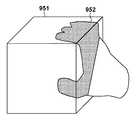
例えば、図7に示すように手指モデル750がCGモデル751にめり込んでいる場合、第1の実施形態では図8に示すように変形移動後の手指モデル850を表示すると共に、移動によって生じた手指の除去領域851をインペインティングしていた。一方、第2の実施形態では手指モデルを直接表示せず、図9に示すようにCGモデル951の表面に操作状態952を表示する。これにより、インペインティングを行わずに利用者に操作状態を提示する。また、図10に示すように現実の手指領域953を半透明表示してもよい。 For example, when the
<処理の手順>
図11は、第2の実施形態の画像処理部1070の処理の手順を示すフローチャートである。ステップS2410では、画像処理部1070は、変形前後の手指モデルに挟まれるCGモデル面を検出して取得する。具体的には、まず、図12に示すような変形前後の手指モデルを包括するモデルを生成する。例えば、変形前の手指モデルの頂点と変形後の手指モデルの頂点を結ぶことで側面に新たな平面を形成したモデルを生成する。次に、生成した手指モデルとCGモデルに対してDepth Peeling(深度剥離)を行うことにより、変形前の手指モデルと変形後の手指モデルとの間に存在するCGモデル面を検出する。<Processing procedure>
FIG. 11 is a flowchart showing a processing procedure of the
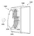
例えば、図13に示すように直方体のCGモデル1300に手指の包括モデル1301(実線と点線を結んだモデル)がめり込んでいる場合、矢印1302の方向からDepth Peelingを行うと、図14に示す4つの深度画像が得られる。ここで、深度画像の画素に対して剥離した面(モデル)のIDを記憶しておき、剥離した順番に深度画像のIDを参照すれば手の内部にあるCGモデル1300の表面を検出できる。 For example, as shown in FIG. 13, when the
例えば、図14の直線部1401では、剥離した順番で深度画像のモデルIDを参照したとき、手前面1510、CGモデル前面1530、手背面1520、CGモデル背面1540の順番で並んでいる。このとき、図14の直線上にある二つ目の深度画像の画素はCGモデルのIDだが、その前後の深度画像の画素は手のIDを持つため、二つ目の深度画像の画素にあるCGモデルは手指のモデル内(図13の黒い領域)に存在することが分かる。ただし、必ずしもCGモデル1300と手指の包括モデル1301との間の衝突面を求める必要はなく、CGモデルの表面に変形後の手指モデルを投影する構成であってもよい。 For example, in the
ステップS2420では、画像処理部1070が撮像画像にCGモデルを重畳し、画像出力部1080が重畳画像を出力して表示部200に表示させる。ステップS2430で、画像出力部1080は、画像処理部1070によりステップS2410で検出したCGモデル面を図9の操作状態952に示すように強調表示する。すなわち、変形前後の手指モデルの間にあるCGモデル面上の手指モデルを強調表示することにより、操作状態を表示する。なお、強調表示する領域に、撮像画像の手指領域画像を利用してもよい。以上で図11の一連の処理が終了する。 In step S2420, the
本実施形態によれば、撮像画像をインペインティングすることなく、利用者にCGモデルをどのように操作しているかを提示することができる。 According to this embodiment, it is possible to show the user how to operate the CG model without inpainting the captured image.
(第3の実施形態)
第1の実施形態では、手指モデルの変形移動に合わせてインペインティングする際に、二次元の画像情報に基づいて補完処理を行う例を説明した。これに対して、第3の実施形態では、現実空間の三次元再構成データを生成し、当該三次元再構成データを用いて補完を行うことにより、現実空間に基づいた撮像画像の補完を行う例を説明する。(Third Embodiment)
In the first embodiment, an example of performing complementary processing based on two-dimensional image information when inpainting according to the deformation movement of the finger model has been described. On the other hand, in the third embodiment, the captured image based on the real space is complemented by generating the three-dimensional reconstruction data in the real space and performing the complement using the three-dimensional reconstruction data. An example will be described.
<構成>
図15は、本実施形態に係る情報処理装置2000の概略構成を示している。第3の実施形態では、第1の実施形態の構成に加えて、三次元再構成部2010が追加されている。三次元再構成部2010は、データ記憶部1020から撮像部100の位置姿勢と撮像画像を取得し、これらの情報を用いて現実物体の三次元点群を生成する。また、生成した三次元点群および色情報をデータ記憶部1020に記憶する。なお、位置姿勢推定部1030は、三次元再構成部2010により抽出された特徴点を用いて位置合わせを行う。<Structure>
FIG. 15 shows a schematic configuration of the
<処理の手順>
図16は、本実施形態に係る三次元再構成部2010、および位置姿勢推定部1030の処理の手順を示すフローチャートである。<Processing procedure>
FIG. 16 is a flowchart showing a processing procedure of the three-
ステップS2510では、三次元再構成部2010は、撮像画像からFAST特徴量を用いて、画像内の特徴点を抽出する。ただし、FAST特徴量に限らずSIFT特徴量やSURF特徴量など特徴点を検出できるものであれば何れでもよい。なお、手の領域内の特徴を抽出する必要はない。 In step S2510, the three-
ステップS2520では、三次元再構成部2010は、抽出した特徴点に対応する過去フレームの撮像画像の特徴点を検出して、データ記憶部1020にフレーム間の対応点情報を保存する。 In step S2520, the three-
ステップS2530では、位置姿勢推定部1030は、フレーム間の対応点情報から特徴点の三次元位置と撮像部100の位置姿勢を算出する。ステップS2540では、三次元再構成部2010は、ステップ画像間の画素毎の対応点を求めて、三角測量の原理により三次元点群を三次元再構成データとして生成する。 In step S2530, the position /
ステップS2550では、三次元再構成部2010は、算出した三次元点群の三次元位置と画素の色情報とをデータ記憶部1020に記憶する。以上で図16の一連の処理が終了する。 In step S2550, the three-
画像処理部1070は、三次元再構成データを用いて、撮像画像の手指領域に対して、三次元再構成した点群を表示した後に、CGモデルと手指モデルを表示する。本実施形態によれば、現実空間の背景を違和感なく表示してCGモデルを操作することができる。 The
(その他の実施形態)
本発明は、上述の実施形態の1以上の機能を実現するプログラムを、ネットワーク又は記憶媒体を介してシステム又は装置に供給し、そのシステム又は装置のコンピュータにおける1つ以上のプロセッサがプログラムを読出し実行する処理でも実現可能である。また、1以上の機能を実現する回路(例えば、ASIC)によっても実現可能である。(Other embodiments)
The present invention supplies a program that realizes one or more functions of the above-described embodiment to a system or device via a network or storage medium, and one or more processors in the computer of the system or device reads and executes the program. It can also be realized by the processing to be performed. It can also be realized by a circuit (for example, ASIC) that realizes one or more functions.
100:撮像部、200:表示部、1000:情報処理装置、1010:画像取得部、1020:データ記憶部、1030:位置姿勢推定部、1040:手指モデル生成部、1050:衝突判定部、1060:制御部、1070:画像処理部、1080:画像出力部、2000:情報処理装置、2010:三次元再構成部 100: Imaging unit, 200: Display unit, 1000: Information processing device, 1010: Image acquisition unit, 1020: Data storage unit, 1030: Position and orientation estimation unit, 1040: Finger model generation unit, 1050: Collision detection unit, 1050: Control unit, 1070: Image processing unit, 1080: Image output unit, 2000: Information processing device, 2010: Three-dimensional reconstruction unit
Claims (4)
Translated fromJapanese前記手指領域から手指モデルを生成する生成手段と、
前記手指モデルと前記撮像画像に重畳されるCGモデルとの衝突判定を行う判定手段と、
前記衝突判定の結果に基づいて前記手指モデルの表示形態を制御する制御手段と、
前記制御手段による前記表示形態の制御の前後の前記手指モデルに挟まれる前記CGモデルの面を取得し、当該面上の手指モデルを識別表示することにより、前記撮像画像における前記CGモデルの表面に手指の操作状態を表示する処理を行う処理手段と、
を備えることを特徴とする情報処理装置。An extraction means that extracts the finger area from the captured image,
A generation means for generating a finger model from the finger region and
A determination means for determining a collision between the finger model and the CG model superimposed on the captured image, and
A control means for controlling the display form of the finger model based on the result of the collision determination, and
By acquiring the surface of the CG model sandwiched between the finger models before and after the control of the display form by the control means and identifying and displaying the finger model on the surface, the surface of the CG model in the captured image is displayed. A processing means for displaying the operation status of fingers and
An information processing device characterized by being equipped with.
撮像画像から手指領域を抽出する抽出工程と、
前記手指領域から手指モデルを生成する生成工程と、
前記手指モデルと前記撮像画像に重畳されるCGモデルとの衝突判定を行う判定工程と、
前記衝突判定の結果に基づいて前記手指モデルの表示形態を制御する制御工程と、
前記制御工程による前記表示形態の制御の前後の前記手指モデルに挟まれる前記CGモデルの面を取得し、当該面上の手指モデルを識別表示することにより、前記撮像画像における前記CGモデルの表面に手指の操作状態を表示する処理を行う処理工程と、
を有することを特徴とする情報処理装置の制御方法。It is a control method for information processing equipment.
An extraction process that extracts the finger area from the captured image,
A generation step of generating a finger model from the finger region and
A determination step of determining a collision between the finger model and the CG model superimposed on the captured image, and
A control process that controls the display form of the finger model based on the result of the collision determination, and
By acquiring the surface of the CG model sandwiched between the finger models before and after the control of the display form by the control step and identifying and displaying the finger model on the surface, the surface of the CG model in the captured image is displayed. A processing process that displays the operation status of fingers and
A method for controlling an information processing device, which comprises.
Priority Applications (2)
| Application Number | Priority Date | Filing Date | Title |
|---|---|---|---|
| JP2016152286AJP6857980B2 (en) | 2016-08-02 | 2016-08-02 | Information processing equipment, control methods and programs for information processing equipment |
| US15/660,532US10140777B2 (en) | 2016-08-02 | 2017-07-26 | Information processing apparatus, method of controlling information processing apparatus, and storage medium |
Applications Claiming Priority (1)
| Application Number | Priority Date | Filing Date | Title |
|---|---|---|---|
| JP2016152286AJP6857980B2 (en) | 2016-08-02 | 2016-08-02 | Information processing equipment, control methods and programs for information processing equipment |
Publications (3)
| Publication Number | Publication Date |
|---|---|
| JP2018022292A JP2018022292A (en) | 2018-02-08 |
| JP2018022292A5 JP2018022292A5 (en) | 2019-09-05 |
| JP6857980B2true JP6857980B2 (en) | 2021-04-14 |
Family
ID=61071743
Family Applications (1)
| Application Number | Title | Priority Date | Filing Date |
|---|---|---|---|
| JP2016152286AActiveJP6857980B2 (en) | 2016-08-02 | 2016-08-02 | Information processing equipment, control methods and programs for information processing equipment |
Country Status (2)
| Country | Link |
|---|---|
| US (1) | US10140777B2 (en) |
| JP (1) | JP6857980B2 (en) |
Families Citing this family (14)
| Publication number | Priority date | Publication date | Assignee | Title |
|---|---|---|---|---|
| US10510186B2 (en) | 2017-12-22 | 2019-12-17 | Adobe Inc. | Digital media environment for intuitive modifications of digital graphics |
| US10388045B2 (en) | 2018-01-04 | 2019-08-20 | Adobe Inc. | Generating a triangle mesh for an image represented by curves |
| JP7129839B2 (en)* | 2018-07-19 | 2022-09-02 | 三菱重工業株式会社 | TRAINING APPARATUS, TRAINING SYSTEM, TRAINING METHOD, AND PROGRAM |
| US10832446B2 (en)* | 2019-01-07 | 2020-11-10 | Adobe Inc. | Bone handle generation |
| US10943375B2 (en) | 2019-04-17 | 2021-03-09 | Adobe Inc. | Multi-state vector graphics |
| WO2020264149A1 (en)* | 2019-06-28 | 2020-12-30 | Magic Leap, Inc. | Fast hand meshing for dynamic occlusion |
| CN113014846B (en)* | 2019-12-19 | 2022-07-22 | 华为技术有限公司 | A video capture control method, electronic device, and computer-readable storage medium |
| KR102773987B1 (en) | 2020-01-16 | 2025-03-04 | 소니그룹주식회사 | Display device, image generation method and program |
| US11836871B2 (en) | 2021-03-22 | 2023-12-05 | Apple Inc. | Indicating a position of an occluded physical object |
| US12039673B2 (en)* | 2021-07-21 | 2024-07-16 | Sony Interactive Entertainment Inc. | Augmented reality artificial intelligence enhance ways user perceive themselves |
| US11941746B2 (en)* | 2021-09-03 | 2024-03-26 | Adobe Inc. | Accurate smooth occluding contours |
| US11631207B2 (en) | 2021-09-09 | 2023-04-18 | Adobe Inc. | Vector object stylization from raster objects |
| IT202100030014A1 (en) | 2021-11-26 | 2023-05-26 | Luxottica Group S P A | ENTIRELY VIRTUAL PROCEDURE FOR MEASUREMENTS OF OPTOMETRIC QUANTITIES. |
| JP2023079161A (en)* | 2021-11-26 | 2023-06-07 | ソニーグループ株式会社 | Display control device, display control method, and program |
Family Cites Families (8)
| Publication number | Priority date | Publication date | Assignee | Title |
|---|---|---|---|---|
| US7472047B2 (en)* | 1997-05-12 | 2008-12-30 | Immersion Corporation | System and method for constraining a graphical hand from penetrating simulated graphical objects |
| JPH11103447A (en)* | 1997-08-01 | 1999-04-13 | Sony Corp | Method and device for repairing moving image and providing medium |
| JP2000209425A (en)* | 1998-11-09 | 2000-07-28 | Canon Inc | Image processing apparatus and method, and storage medium |
| JP4522129B2 (en)* | 2004-03-31 | 2010-08-11 | キヤノン株式会社 | Image processing method and image processing apparatus |
| JP6194747B2 (en)* | 2013-10-24 | 2017-09-13 | 富士通株式会社 | Mapping processing program, method and apparatus |
| CN111986328B (en)* | 2013-12-17 | 2025-02-07 | 索尼公司 | Information processing device and method, and non-volatile computer-readable storage medium |
| JP6417702B2 (en)* | 2014-05-01 | 2018-11-07 | 富士通株式会社 | Image processing apparatus, image processing method, and image processing program |
| CN204480228U (en) | 2014-08-08 | 2015-07-15 | 厉动公司 | motion sensing and imaging device |
- 2016
- 2016-08-02JPJP2016152286Apatent/JP6857980B2/enactiveActive
- 2017
- 2017-07-26USUS15/660,532patent/US10140777B2/enactiveActive
Also Published As
| Publication number | Publication date |
|---|---|
| US20180040169A1 (en) | 2018-02-08 |
| US10140777B2 (en) | 2018-11-27 |
| JP2018022292A (en) | 2018-02-08 |
Similar Documents
| Publication | Publication Date | Title |
|---|---|---|
| JP6857980B2 (en) | Information processing equipment, control methods and programs for information processing equipment | |
| CN109561296B (en) | Image processing apparatus, image processing method, image processing system, and storage medium | |
| EP3850588B1 (en) | Method and system for generating a 3d reconstruction of a human | |
| US9594950B2 (en) | Depth mapping with enhanced resolution | |
| CN106846403B (en) | Method and device for positioning hand in three-dimensional space and intelligent equipment | |
| JP6587421B2 (en) | Information processing apparatus, information processing method, and program | |
| CN103140879B (en) | Information presentation device, digital camera, head mounted display, projecting apparatus, information demonstrating method and information are presented program | |
| TWI536320B (en) | Method for image segmentation | |
| KR20160147450A (en) | The bare hand interaction apparatus and method for augmented rearity using rgb-d images | |
| JP5965293B2 (en) | Camera pose estimation device and camera pose estimation program | |
| JP4938748B2 (en) | Image recognition apparatus and program | |
| US12211139B2 (en) | Method for capturing and displaying a video stream | |
| JP5526465B2 (en) | Nail position data detection device, nail position data detection method, and nail position data detection program | |
| JP2016071645A (en) | Object three-dimensional model restoration method, apparatus and program | |
| JP2018129007A (en) | Learning data generation apparatus, learning apparatus, estimation apparatus, learning data generation method, and computer program | |
| KR101696007B1 (en) | Method and device for creating 3d montage | |
| JP6196562B2 (en) | Subject information superimposing apparatus, subject information superimposing method, and program | |
| KR20200117685A (en) | Method for recognizing virtual objects, method for providing augmented reality content using the virtual objects and augmented brodadcasting system using the same | |
| KR20160046399A (en) | Method and Apparatus for Generation Texture Map, and Database Generation Method | |
| JP7520539B2 (en) | Image processing device, image processing method, and program | |
| WO2025057379A1 (en) | Posture estimation system, posture estimation method, and program | |
| JP7029253B2 (en) | Information processing equipment and its method | |
| JP7321029B2 (en) | CALIBRATION DEVICE AND ITS CONTROL METHOD, PROGRAM AND STORAGE MEDIUM | |
| JP2023003929A (en) | Skeleton Recognition Method, Skeleton Recognition Program, and Gymnastics Scoring Support System | |
| WO2018173205A1 (en) | Information processing system, method for controlling same, and program |
Legal Events
| Date | Code | Title | Description |
|---|---|---|---|
| A521 | Request for written amendment filed | Free format text:JAPANESE INTERMEDIATE CODE: A523 Effective date:20190724 | |
| A621 | Written request for application examination | Free format text:JAPANESE INTERMEDIATE CODE: A621 Effective date:20190724 | |
| A977 | Report on retrieval | Free format text:JAPANESE INTERMEDIATE CODE: A971007 Effective date:20200812 | |
| A131 | Notification of reasons for refusal | Free format text:JAPANESE INTERMEDIATE CODE: A131 Effective date:20200824 | |
| A521 | Request for written amendment filed | Free format text:JAPANESE INTERMEDIATE CODE: A523 Effective date:20201022 | |
| A131 | Notification of reasons for refusal | Free format text:JAPANESE INTERMEDIATE CODE: A131 Effective date:20201106 | |
| A521 | Request for written amendment filed | Free format text:JAPANESE INTERMEDIATE CODE: A523 Effective date:20201225 | |
| RD01 | Notification of change of attorney | Free format text:JAPANESE INTERMEDIATE CODE: A7421 Effective date:20210103 | |
| A521 | Request for written amendment filed | Free format text:JAPANESE INTERMEDIATE CODE: A523 Effective date:20210113 | |
| TRDD | Decision of grant or rejection written | ||
| A01 | Written decision to grant a patent or to grant a registration (utility model) | Free format text:JAPANESE INTERMEDIATE CODE: A01 Effective date:20210222 | |
| A61 | First payment of annual fees (during grant procedure) | Free format text:JAPANESE INTERMEDIATE CODE: A61 Effective date:20210323 | |
| R151 | Written notification of patent or utility model registration | Ref document number:6857980 Country of ref document:JP Free format text:JAPANESE INTERMEDIATE CODE: R151 |