JP6856335B2 - Processing equipment - Google Patents
Processing equipmentDownload PDFInfo
- Publication number
- JP6856335B2 JP6856335B2JP2016173459AJP2016173459AJP6856335B2JP 6856335 B2JP6856335 B2JP 6856335B2JP 2016173459 AJP2016173459 AJP 2016173459AJP 2016173459 AJP2016173459 AJP 2016173459AJP 6856335 B2JP6856335 B2JP 6856335B2
- Authority
- JP
- Japan
- Prior art keywords
- wafer
- polishing
- gettering
- holding table
- grinding
- Prior art date
- Legal status (The legal status is an assumption and is not a legal conclusion. Google has not performed a legal analysis and makes no representation as to the accuracy of the status listed.)
- Active
Links
Images


Classifications
- B—PERFORMING OPERATIONS; TRANSPORTING
- B24—GRINDING; POLISHING
- B24B—MACHINES, DEVICES, OR PROCESSES FOR GRINDING OR POLISHING; DRESSING OR CONDITIONING OF ABRADING SURFACES; FEEDING OF GRINDING, POLISHING, OR LAPPING AGENTS
- B24B7/00—Machines or devices designed for grinding plane surfaces on work, including polishing plane glass surfaces; Accessories therefor
- B24B7/20—Machines or devices designed for grinding plane surfaces on work, including polishing plane glass surfaces; Accessories therefor characterised by a special design with respect to properties of the material of non-metallic articles to be ground
- B24B7/22—Machines or devices designed for grinding plane surfaces on work, including polishing plane glass surfaces; Accessories therefor characterised by a special design with respect to properties of the material of non-metallic articles to be ground for grinding inorganic material, e.g. stone, ceramics, porcelain
- B24B7/228—Machines or devices designed for grinding plane surfaces on work, including polishing plane glass surfaces; Accessories therefor characterised by a special design with respect to properties of the material of non-metallic articles to be ground for grinding inorganic material, e.g. stone, ceramics, porcelain for grinding thin, brittle parts, e.g. semiconductors, wafers
- B—PERFORMING OPERATIONS; TRANSPORTING
- B24—GRINDING; POLISHING
- B24B—MACHINES, DEVICES, OR PROCESSES FOR GRINDING OR POLISHING; DRESSING OR CONDITIONING OF ABRADING SURFACES; FEEDING OF GRINDING, POLISHING, OR LAPPING AGENTS
- B24B37/00—Lapping machines or devices; Accessories
- B24B37/04—Lapping machines or devices; Accessories designed for working plane surfaces
- B—PERFORMING OPERATIONS; TRANSPORTING
- B24—GRINDING; POLISHING
- B24B—MACHINES, DEVICES, OR PROCESSES FOR GRINDING OR POLISHING; DRESSING OR CONDITIONING OF ABRADING SURFACES; FEEDING OF GRINDING, POLISHING, OR LAPPING AGENTS
- B24B27/00—Other grinding machines or devices
- B24B27/0023—Other grinding machines or devices grinding machines with a plurality of working posts
- B—PERFORMING OPERATIONS; TRANSPORTING
- B24—GRINDING; POLISHING
- B24B—MACHINES, DEVICES, OR PROCESSES FOR GRINDING OR POLISHING; DRESSING OR CONDITIONING OF ABRADING SURFACES; FEEDING OF GRINDING, POLISHING, OR LAPPING AGENTS
- B24B27/00—Other grinding machines or devices
- B24B27/0069—Other grinding machines or devices with means for feeding the work-pieces to the grinding tool, e.g. turntables, transfer means
- B—PERFORMING OPERATIONS; TRANSPORTING
- B24—GRINDING; POLISHING
- B24B—MACHINES, DEVICES, OR PROCESSES FOR GRINDING OR POLISHING; DRESSING OR CONDITIONING OF ABRADING SURFACES; FEEDING OF GRINDING, POLISHING, OR LAPPING AGENTS
- B24B27/00—Other grinding machines or devices
- B24B27/0076—Other grinding machines or devices grinding machines comprising two or more grinding tools
- B—PERFORMING OPERATIONS; TRANSPORTING
- B24—GRINDING; POLISHING
- B24B—MACHINES, DEVICES, OR PROCESSES FOR GRINDING OR POLISHING; DRESSING OR CONDITIONING OF ABRADING SURFACES; FEEDING OF GRINDING, POLISHING, OR LAPPING AGENTS
- B24B37/00—Lapping machines or devices; Accessories
- B24B37/04—Lapping machines or devices; Accessories designed for working plane surfaces
- B24B37/07—Lapping machines or devices; Accessories designed for working plane surfaces characterised by the movement of the work or lapping tool
- B24B37/10—Lapping machines or devices; Accessories designed for working plane surfaces characterised by the movement of the work or lapping tool for single side lapping
- B—PERFORMING OPERATIONS; TRANSPORTING
- B24—GRINDING; POLISHING
- B24B—MACHINES, DEVICES, OR PROCESSES FOR GRINDING OR POLISHING; DRESSING OR CONDITIONING OF ABRADING SURFACES; FEEDING OF GRINDING, POLISHING, OR LAPPING AGENTS
- B24B37/00—Lapping machines or devices; Accessories
- B24B37/27—Work carriers
- B24B37/30—Work carriers for single side lapping of plane surfaces
- B—PERFORMING OPERATIONS; TRANSPORTING
- B24—GRINDING; POLISHING
- B24B—MACHINES, DEVICES, OR PROCESSES FOR GRINDING OR POLISHING; DRESSING OR CONDITIONING OF ABRADING SURFACES; FEEDING OF GRINDING, POLISHING, OR LAPPING AGENTS
- B24B37/00—Lapping machines or devices; Accessories
- B24B37/34—Accessories
- B24B37/345—Feeding, loading or unloading work specially adapted to lapping
- B—PERFORMING OPERATIONS; TRANSPORTING
- B24—GRINDING; POLISHING
- B24B—MACHINES, DEVICES, OR PROCESSES FOR GRINDING OR POLISHING; DRESSING OR CONDITIONING OF ABRADING SURFACES; FEEDING OF GRINDING, POLISHING, OR LAPPING AGENTS
- B24B57/00—Devices for feeding, applying, grading or recovering grinding, polishing or lapping agents
- B24B57/02—Devices for feeding, applying, grading or recovering grinding, polishing or lapping agents for feeding of fluid, sprayed, pulverised, or liquefied grinding, polishing or lapping agents
- H—ELECTRICITY
- H01—ELECTRIC ELEMENTS
- H01L—SEMICONDUCTOR DEVICES NOT COVERED BY CLASS H10
- H01L21/00—Processes or apparatus adapted for the manufacture or treatment of semiconductor or solid state devices or of parts thereof
- H01L21/02—Manufacture or treatment of semiconductor devices or of parts thereof
- H01L21/04—Manufacture or treatment of semiconductor devices or of parts thereof the devices having potential barriers, e.g. a PN junction, depletion layer or carrier concentration layer
- H01L21/18—Manufacture or treatment of semiconductor devices or of parts thereof the devices having potential barriers, e.g. a PN junction, depletion layer or carrier concentration layer the devices having semiconductor bodies comprising elements of Group IV of the Periodic Table or AIIIBV compounds with or without impurities, e.g. doping materials
- H01L21/30—Treatment of semiconductor bodies using processes or apparatus not provided for in groups H01L21/20 - H01L21/26
- H01L21/302—Treatment of semiconductor bodies using processes or apparatus not provided for in groups H01L21/20 - H01L21/26 to change their surface-physical characteristics or shape, e.g. etching, polishing, cutting
- H01L21/304—Mechanical treatment, e.g. grinding, polishing, cutting
- H—ELECTRICITY
- H01—ELECTRIC ELEMENTS
- H01L—SEMICONDUCTOR DEVICES NOT COVERED BY CLASS H10
- H01L21/00—Processes or apparatus adapted for the manufacture or treatment of semiconductor or solid state devices or of parts thereof
- H01L21/02—Manufacture or treatment of semiconductor devices or of parts thereof
- H01L21/04—Manufacture or treatment of semiconductor devices or of parts thereof the devices having potential barriers, e.g. a PN junction, depletion layer or carrier concentration layer
- H01L21/18—Manufacture or treatment of semiconductor devices or of parts thereof the devices having potential barriers, e.g. a PN junction, depletion layer or carrier concentration layer the devices having semiconductor bodies comprising elements of Group IV of the Periodic Table or AIIIBV compounds with or without impurities, e.g. doping materials
- H01L21/30—Treatment of semiconductor bodies using processes or apparatus not provided for in groups H01L21/20 - H01L21/26
- H01L21/302—Treatment of semiconductor bodies using processes or apparatus not provided for in groups H01L21/20 - H01L21/26 to change their surface-physical characteristics or shape, e.g. etching, polishing, cutting
- H01L21/306—Chemical or electrical treatment, e.g. electrolytic etching
- H01L21/30625—With simultaneous mechanical treatment, e.g. mechanico-chemical polishing
Landscapes
- Engineering & Computer Science (AREA)
- Mechanical Engineering (AREA)
- Computer Hardware Design (AREA)
- Physics & Mathematics (AREA)
- Condensed Matter Physics & Semiconductors (AREA)
- General Physics & Mathematics (AREA)
- Manufacturing & Machinery (AREA)
- Microelectronics & Electronic Packaging (AREA)
- Power Engineering (AREA)
- Ceramic Engineering (AREA)
- Inorganic Chemistry (AREA)
- Chemical & Material Sciences (AREA)
- Mechanical Treatment Of Semiconductor (AREA)
- Finish Polishing, Edge Sharpening, And Grinding By Specific Grinding Devices (AREA)
- Grinding Of Cylindrical And Plane Surfaces (AREA)
Description
Translated fromJapanese本発明は、ウエーハを加工するとともに所望のゲッタリング層をウエーハの被加工面に形成する加工装置に関する。 The present invention relates to a processing apparatus for processing a wafer and forming a desired gettering layer on the surface to be processed of the wafer.
ウエーハを研削砥石で研削して薄化すると、ウエーハの被加工面に加工歪みなどが生じてチップの抗折強度が低下するため、ウエーハを研削した後に、スラリーを用いずに乾式で研磨するドライポリッシュやCMP(Chemical Mechanical Polishing)と呼ばれる化学的機械的研磨法によってウエーハの被加工面を研磨して加工歪みを除去している。 When the wafer is ground with a grinding wheel to make it thinner, processing distortion occurs on the surface to be processed of the wafer and the bending strength of the chip decreases. Therefore, after grinding the wafer, dry polishing without using a slurry is performed. The surface to be processed of the wafer is polished by a chemical mechanical polishing method called polishing or CMP (Chemical Mechanical Polishing) to remove processing distortion.
ここで、加工歪みが除去されたウエーハには、デバイスの金属汚染の原因となる金属不純物を捕獲するゲッタリング効果が消失してしまうという問題が生じている。そこで、ウエーハにゲッタリング効果を生じさせるゲッタリング層を形成する加工装置として、例えば下記の特許文献1に示すものがある。この加工装置においては、ウエーハを研削した後、研磨手段によりCMPによる研磨を施し、その後、スラリーを純水に切り換えて、純水をウエーハの裏面と研磨パッドの研磨面との間に供給しながらウエーハの裏面にゲッタリング層を形成している。 Here, the wafer from which the processing strain has been removed has a problem that the gettering effect of capturing metal impurities that cause metal contamination of the device is lost. Therefore, as a processing device for forming a gettering layer that causes a gettering effect on a wafer, for example, there is one shown in Patent Document 1 below. In this processing device, after grinding the wafer, polishing by CMP is performed by a polishing means, and then the slurry is switched to pure water to supply pure water between the back surface of the wafer and the polished surface of the polishing pad. A gettering layer is formed on the back surface of the wafer.
しかし、上記の加工装置においてスラリーと純水とを切り換えて、ウエーハの裏面にゲッタリング層を形成するためには、研磨パッドにスラリーが完全に付着していない状態にする必要がある。つまり、研磨パッドにスラリーが付着した状態では、ウエーハの裏面に所望のゲッタリング層を形成することができず、研磨パッドを洗浄等する必要がある。そのため、ウエーハの研削・研磨が終了しているのにもかかわらず、ゲッタリング層を形成するのに時間がかかるという問題がある。 However, in order to switch between the slurry and pure water in the above processing apparatus and form the gettering layer on the back surface of the wafer, it is necessary to make the slurry not completely adhered to the polishing pad. That is, when the slurry is attached to the polishing pad, a desired gettering layer cannot be formed on the back surface of the wafer, and it is necessary to clean the polishing pad. Therefore, there is a problem that it takes time to form the gettering layer even though the grinding and polishing of the wafer have been completed.
本発明は、上記の事情に鑑みてなされたものであり、時間をかけることなくウエーハの被加工面に所望のゲッタリング層を形成できるようにすることを目的としている。 The present invention has been made in view of the above circumstances, and an object of the present invention is to enable a desired gettering layer to be formed on a surface to be processed of a wafer without taking time.
本発明は、ウエーハの被加工面に研削と研磨とを施した後、該被加工面にゲッタリング層を形成する加工装置であって、中心を軸に自転可能に配設されウエーハを搬入出する搬入出領域とウエーハを研削する研削領域とウエーハを研磨する研磨領域とにウエーハを位置合わせするターンテーブルと、該ターンテーブルの中心を中心に等角度で配設されウエーハを保持する保持面を有する保持テーブルと、該搬入出領域に位置づけられた該保持テーブルに対してウエーハを搬入及び搬出する搬送手段と、該研削領域に位置づけられた該保持テーブルに保持されたウエーハを研削して所定の厚みに形成する研削手段と、該研磨領域に位置づけられた該保持テーブルに保持されたウエーハの被加工面を研磨する研磨手段と、該搬入出領域に位置づけられた該保持テーブルに保持されたウエーハの被加工面にゲッタリング層を形成するゲッタリング層形成手段と、を備え、該ゲッタリング層形成手段は、円板状のゲッタリングパッドが装着されたマウントの中心を軸に回転するスピンドルを有する回転手段と、該回転手段を該保持テーブルの該保持面に対して垂直方向に昇降させる昇降手段と、該ゲッタリングパッドの中心から純水をウエーハに供給する純水供給手段と、該ゲッタリングパッドをドレスするドレス部材と、を備える。The present invention is a processing device that forms a gettering layer on the surface to be processed after grinding and polishing the surface to be processed of the waiha, and is arranged so as to be rotatable around the center to carry in and out the waha. A turntable that aligns the waiha with the loading / unloading area, the grinding area that grinds the waha, and the polishing area that grinds the waha, and a holding surface that is arranged at an equal angle around the center of the turntable and holds the waha. A holding table to be held, a transport means for carrying in and out of a waha to the holding table located in the carry-in / out area, and a waha held in the holding table located in the grinding area are ground to be predetermined. A grinding means formed to a thickness, a polishing means for polishing the surface to be processed of a wafer held on the holding table located in the polishing region, and a wafer held on the holding table located in the loading / unloading region. A gettering layer forming means for forming a gettering layer on the surface to be processed, and the gettering layer forming means includes a spindle that rotates about the center of a mount on which a disc-shaped gettering pad is mounted. A rotating means, an elevating means for raising and lowering the rotating means in a direction perpendicular to the holding surface of the holding table, a pure water supply means for supplying pure water from the center of the gettering pad to the wafer, and the getter. It is providedwith a dress member for dressing a ring pad.
また、上記回転手段を上記保持テーブルの上記保持面に平行な水平方向に移動させる水平移動手段を備え、前記ゲッタリングパッドを前記搬入出領域から退避可能とする構成でもよい。
Further, a horizontal moving means for moving therotating means in the horizontal direction parallel to the holding surface of the holding tablemay be provided so that the gettering pad can be retracted from the carry-in / out area .
本発明にかかる加工装置は、中心を軸に自転可能に配設され搬入出領域,研削領域,研磨領域にウエーハを位置合わせするターンテーブルと、ターンテーブルの中心を中心に等角度で配設されウエーハを保持する保持面を有する保持テーブルと、搬入出領域に位置づけられた保持テーブルに対してウエーハを搬入及び搬出する搬送手段と、研削領域に位置づけられた保持テーブルに保持されたウエーハを研削して所定の厚みに形成する研削手段と、研磨領域に位置づけられた保持テーブルに保持されたウエーハの被加工面を研磨する研磨手段と、搬入出領域に位置づけられた保持テーブルに保持されたウエーハの被加工面にゲッタリング層を形成するゲッタリング層形成手段とを備え、ゲッタリング層形成手段は、円板状のゲッタリングパッドが装着されたマウントの中心を軸に回転するスピンドルを有する回転手段と、回転手段を保持テーブルの保持面に対して垂直方向に昇降させる昇降手段とを備えたため、ウエーハに対して研削・研磨を施した後、ターンテーブルが回転して保持テーブルを搬入出領域に位置づけることで、研磨手段と別機構であるゲッタリング層形成手段により、時間をかけることなくウエーハの被加工面にゲッタリング層を形成することができる。 The processing apparatus according to the present invention is arranged so as to be rotatable about the center, and is arranged at an equal angle around the center of the turntable and a turntable that aligns the waiha with the carry-in / out area, the grinding area, and the polishing area. A holding table having a holding surface for holding the waha, a transport means for carrying in and out the waha with respect to the holding table located in the carry-in / out area, and a waha held in the holding table located in the grinding area are ground. The grinding means formed to a predetermined thickness, the polishing means for polishing the surface to be processed of the waha held on the holding table located in the polishing area, and the waha held on the holding table located in the carry-in / out area. A means for forming a gettering layer for forming a gettering layer on a surface to be processed is provided, and the means for forming a gettering layer has a rotating means having a spindle that rotates about the center of a mount on which a disk-shaped gettering pad is mounted. Since it is equipped with a means for raising and lowering the rotating means in a direction perpendicular to the holding surface of the holding table, the turntable rotates to move the holding table to the loading / unloading area after grinding and polishing the wafer. By positioning, the gettering layer can be formed on the surface to be processed of the wafer without taking time by the gettering layer forming means which is a mechanism different from the polishing means.
上記回転手段を上記保持テーブルの上記保持面に対して水平方向に移動させる水平移動手段を備える場合は、上記搬入出領域に位置づけられた上記保持テーブルに対するウエーハの搬入及び搬出の妨げとならない位置にゲッタリング層形成手段を位置づけることができ、上記同様に、時間をかけることなくウエーハの被加工面にゲッタリング層を形成することができる。 When the horizontal moving means for moving the rotating means in the horizontal direction with respect to the holding surface of the holding table is provided, the position does not hinder the loading and unloading of the wafer with respect to the holding table located in the loading / unloading area. The gettering layer forming means can be positioned, and similarly to the above, the gettering layer can be formed on the surface to be processed of the wafer without taking time.
図1に示す加工装置1は、被加工物であるウエーハに研削・研磨を施す加工装置の一例である。加工装置1は、Y軸方向に延在する装置ベース100と、装置ベース100のY軸方向後部において立設された直立壁101とを有している。本実施形態に示す加工装置1は、ウエーハを搬入出するための搬入出領域P1と、加工前のウエーハを粗研削するための粗研削領域P2と、粗研削後のウエーハを仕上げ研削するための仕上げ研削領域P3と、仕上げ研削後のウエーハを研磨するための研磨領域P4とを備えている。 The processing device 1 shown in FIG. 1 is an example of a processing device that grinds and polishes a wafer as a workpiece. The processing apparatus 1 has an
装置ベース100の上面中央には、中心を軸に自転可能なターンテーブル2が配設され、ターンテーブル2の上には、ウエーハを保持する保持テーブル3が配設されている。保持テーブル3は、ターンテーブル2の中心を中心にして等角度の間隔を設けて少なくとも4つ配設されている。ターンテーブル2の上面には、各保持テーブル3が配設された領域を仕切るための仕切り板4が配設されている。仕切り板4の高さは、保持テーブル3の高さよりも高くなっている。そして、ターンテーブル2が回転することにより、保持テーブル3を公転させ、保持テーブル3を搬入出領域P1と、粗研削領域P2と、仕上げ研削領域P3と、研磨領域P4とに順次位置づけることができる。 A
装置ベース100のY軸方向前部には、ステージ102a,102bが隣接して配設されている。ステージ102aには研削前のウエーハを収容するカセット5aが配設され、ステージ102bには研削後のウエーハを収容するカセット5bが配設されている。カセット5a及びカセット5bの近傍には、カセット5aからの加工前のウエーハの搬出を行うとともにカセット5bへの加工後のウエーハの搬入を行う搬入出手段6が配設されている。搬入出手段6には、X軸方向移動手段7が接続されている。そして、X軸方向移動手段7によって搬入出手段6をX軸方向に水平移動させることにより、カセット5a又はカセット5bに対面した位置に搬入出手段6を位置づけることができる。
搬入出領域P1の近傍には、加工前のウエーハを仮置きして中心位置合わせを行う仮置き手段8が配設されている。仮置き手段8に隣接した位置には、加工後のウエーハを洗浄する洗浄手段9が配設されている。 In the vicinity of the carry-in / out area P1, a temporary placing means 8 for temporarily placing the wafer before processing and aligning the center is arranged. A cleaning means 9 for cleaning the processed wafer is arranged at a position adjacent to the temporary placing means 8.
加工装置1は、搬入出領域P1に位置づけられた保持テーブル3に対してウエーハを搬入及び搬出する搬送手段10と、粗研削領域P2に位置づけられた保持テーブル3に保持されたウエーハを所定の厚みに粗研削する粗研削手段20と、粗研削手段20を保持テーブル3に対して垂直方向(Z軸方向)に研削送りする粗研削送り手段30と、仕上げ研削領域P3に位置づけられた保持テーブル3に保持されたウエーハを所定の仕上げ厚みに仕上げ研削する仕上げ研削手段40と、仕上げ研削手段40を保持テーブル3に対してZ軸方向に研削送りする仕上げ研削送り手段50と、研磨領域P4に位置づけられた保持テーブル3に保持されたウエーハの被加工面を研磨する研磨手段60と、搬入出領域P1に位置づけられた保持テーブルに保持されたウエーハの被加工面にゲッタリング層を形成するゲッタリング層形成手段70とを備えている。 The processing apparatus 1 has a transport means 10 for loading and unloading the waha with respect to the holding table 3 located in the loading / unloading region P1, and a waha held in the holding table 3 positioned in the rough grinding region P2 with a predetermined thickness. The rough grinding means 20 for rough grinding, the rough grinding feeding means 30 for grinding and feeding the rough grinding means 20 in the direction perpendicular to the holding table 3 (Z-axis direction), and the holding table 3 positioned in the finish grinding area P3. Positioned in the polishing area P4, the finish grinding means 40 that finish-grinds the wafer held in the above to a predetermined finish thickness, the finish grinding feed means 50 that grinds and feeds the finish grinding means 40 with respect to the holding table 3 in the Z-axis direction. Polishing means 60 for polishing the work surface of the waier held on the holding table 3 and gettering for forming a gettering layer on the work surface of the waha held on the holding table located in the carry-in / out area P1. It is provided with a
搬送手段10は、ウエーハを吸着する円板状の吸着パッド11と、吸着パッド11を支持するアーム部12と、アーム部12を支持する支持ロッド13と、装置ベース100に取り付けられた一対の支持柱15と、一対の支持柱15の上端に固定されたY軸方向に延在する案内レール16と、支持ロッド13の上端に連結され案内レール16に沿ってY軸方向に往復移動する移動ブロック14とを備えている。支持ロッド13は、図示しない昇降機構によってZ軸方向に昇降可能となっている。このように構成される搬送手段10は、仮置き手段8に仮置きされた加工前のウエーハを搬入出領域P1に位置づけられた保持テーブル3に搬送するとともに、搬入出領域P1に位置づけられた保持テーブル3から加工後のウエーハを搬出して洗浄手段9に搬送することができる。 The transport means 10 includes a disk-
粗研削手段20は、直立壁101の側方において粗研削送り手段30を介して配設され、粗研削領域P2に配置されている。粗研削手段20は、Z軸方向の軸心を有するスピンドル21と、スピンドル21を回転可能に支持するスピンドルハウジング22と、スピンドル21の上端に接続されたモータ23と、スピンドル21の下端に装着された粗研削ホイール24と、粗研削ホイール24の下部に環状に固着された粗研削用の研削砥石25とを備えている。そして、モータ23がスピンドル21を回転させることにより、粗研削ホイール24を所定の回転速度で回転させることができる。 The rough grinding means 20 is arranged on the side of the
粗研削送り手段30は、Z軸方向に延在するボールネジ31と、ボールネジ31の一端に接続されたモータ32と、ボールネジ31と平行に延在する一対のガイドレール33と、一方の面が粗研削手段20に連結された昇降板34とを備えている。昇降板34の他方の面に形成された一対の案内溝340にガイドレール33が摺接し、昇降板34の中央部に形成されたナットにはボールネジ31が螺合している。モータ32によってボールネジ31が回動することにより、一対のガイドレール33に沿って昇降板34とともに粗研削手段20をZ軸方向に昇降させることができる。 The rough grinding feed means 30 has a
仕上げ研削手段40は、直立壁101の側方において仕上げ研削送り手段50を介して配設され、仕上げ研削領域P3に配置されている。仕上げ研削手段40は、Z軸方向の軸心を有するスピンドル41と、スピンドル41を回転可能に支持するスピンドルハウジング42と、スピンドル41の上端に接続されたモータ43と、スピンドル41の下端に装着された仕上げ研削ホイール44と、仕上げ研削ホイール44の下部に環状に固着された仕上げ研削用の研削砥石45とを備えている。モータ43がスピンドル41を回転させることにより、仕上げ研削ホイール44を所定の回転速度で回転させることができる。 The finish grinding means 40 is arranged on the side of the
仕上げ研削送り手段50は、Z軸方向に延在するボールネジ51と、ボールネジ51の一端に接続されたモータ52と、ボールネジ51と平行に延在する一対のガイドレール53と、一方の面が仕上げ研削手段40に連結された昇降板54とを備えている。昇降板54の他方の面に形成された一対の案内溝540にガイドレール53が摺接し、昇降板54の中央部に形成されたナットにはボールネジ51が螺合している。モータ52によってボールネジ51が回動することにより、一対のガイドレール53に沿って昇降板54とともに仕上げ研削手段40をZ軸方向に昇降させることができる。 The finish grinding feed means 50 has a
研磨手段60は、二点鎖線に示すように、装置ベース100の上に配設され、研磨領域P4に配置されている。研磨手段60は、図2に示すように、ウエーハの被加工面を研磨する研磨ホイール62と、研磨ホイール62を回転させる回転手段61と、回転手段61をZ軸方向に昇降可能に支持する可動ブロック63と、可動ブロック63に配設され回転手段61をZ軸方向に昇降させる第1研磨送り手段65と、可動ブロック63をX軸方向に移動可能に支持する固定ブロック64と、固定ブロック64に配設され可動ブロック63を保持テーブル3の保持面3aに対して平行なX軸方向に移動させる第2研磨送り手段66とを備えている。 The polishing means 60 is arranged on the
回転手段61は、Z軸方向の軸心を有するスピンドル610と、スピンドル610の上端に接続されたモータ611と、スピンドル610を回転可能に支持するスピンドルハウジング612とを備えている。研磨ホイール62は、スピンドル610の下端に着脱可能にマウント620を介して装着された基台621と、基台621の下部に装着された円板状の研磨パッド622とを備えている。そして、回転手段61は、モータ611を駆動することにより、マウント620の中心を軸にして研磨パッド622を所定の回転速度で回転させることができる。 The rotating means 61 includes a
研磨パッド622は、例えば発泡ウレタンや不織布中に砥粒を分散させ適宜のボンド材によって固定した研磨パッドによって構成される。砥粒は、例えば粒径が0.2〜1.5μmのGC(Green Carbide)砥粒を用いることができる。また、砥粒はウエーハの硬度よりも高くウエーハの被加工面に微小な傷をつけることができるものであればよい。砥粒としては、GC砥粒のほか、ダイヤモンド、アルミナ、セリア、CBN等の砥粒でもよい。研磨手段60によってCMPによる研磨加工を行う場合は、図示していないが、研磨パッド622と保持テーブル3が保持するウエーハの被加工面との間にスラリーを供給するスラリー供給源が接続されている。なお、スラリーは、アルカリ性の研磨液を用いることが多いが、加工対象となるウエーハの材質に応じて酸性の研磨液を用いるようにしてもよい。また、研磨手段60で乾式の研磨加工(ドライポリッシュ)を行うようにしてもよい。 The
第1研磨送り手段65は、Z軸方向に延在する図示しないボールネジと、ボールネジの一端に接続されたモータ650とを備えている。可動ブロック63の側面には、Z軸方向に延在する一対のガイドレール630が形成され、この一対のガイドレール630にスピンドルハウジング612に形成された一対の案内溝613が摺接し、スピンドルハウジング612の中央のナットにはボールネジが螺合している。そして、モータ650によってボールネジが回動することにより、一対のガイドレール630に沿って回転手段61とともに研磨ホイール62をZ軸方向に移動させることができる。 The first polishing feed means 65 includes a ball screw (not shown) extending in the Z-axis direction and a
第2研磨送り手段66は、X軸方向に延在する図示しないボールネジと、ボールネジの一端に接続されたモータ660とを備えている。固定ブロック64の側面には、X軸方向に延在する一対のガイドレール640が形成され、この一対のガイドレール640に可動ブロック63に形成された一対の案内溝631が摺接し、可動ブロック63の中央のナットにはボールネジが螺合している。そして、モータ660によってボールネジが回動することにより、一対のガイドレール640に沿って可動ブロック63をX軸方向に移動させることができる。 The second polishing feed means 66 includes a ball screw (not shown) extending in the X-axis direction and a
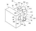
図1に示すゲッタリング層形成手段70は、研磨手段60の近傍に配設され、搬入出領域P1に配置されている。ゲッタリング層形成手段70は、図3に示すように、ウエーハの被加工面にゲッタリング層を形成するゲッタリングホイール72と、ゲッタリングホイール72を回転させる回転手段71と、回転手段71をZ軸方向に昇降可能に支持する可動ブロック73と、回転手段71を図1に示した保持テーブル3の保持面3aに対して垂直方向(Z軸方向)に昇降させる昇降手段75と、可動ブロック73をY軸方向に移動可能に支持する固定ブロック74と、固定ブロック74に配設され可動ブロック73を保持テーブル3の保持面3aに対して水平方向(Y軸方向)に移動させる水平移動手段76とを備えている。 The gettering
回転手段71は、Z軸方向の軸心を有するスピンドル710と、スピンドル710の上端に接続されたモータ711と、スピンドル710を回転可能に支持するスピンドルハウジング712とを備えている。ゲッタリングホイール72は、スピンドル710の下端に着脱可能にマウント720を介して装着された基台721と、基台721の下部に装着された円板状のゲッタリングパッド722とを備えている。そして、ゲッタリング層形成手段70は、モータ711を駆動することにより、マウント720の中心を軸にしてゲッタリングパッド722を所定の回転速度で回転させることができる。 The rotating means 71 includes a
ゲッタリングパッド722の直径は、例えば、図1に示した保持テーブル3の保持面3aの半径以上、かつ直径以下となっている。ゲッタリングパッド722は、上記の研磨パッド622と同様に、例えば発泡ウレタンや不織布中に例えば、GC、ダイヤモンド、アルミナ、セリア、CBN等の砥粒を分散させ適宜のボンド材によって固定したものである。砥粒については、研磨パッド622に分散されている砥粒の粒径よりも小さい粒径の砥粒を分散したものが用いられている。ゲッタリング層形成手段70には、図4に示すように、純水供給源90が接続されている。純水供給源90は、ゲッタリングパッド722の中心からウエーハとゲッタリングパッド722とが接触する部分に所定の流量の純水を供給する構成となっている。なお、形成するゲッタリング層によっては、ゲッタリングパッド722に分散される砥粒の粒径が、研磨パッド622に分散されている砥粒の粒径以上であってもよい。 The diameter of the
図3に示す昇降手段75は、Z軸方向に延在する図示しないボールネジと、ボールネジの一端に接続されたモータ750とを備えている。可動ブロック73の側面73aには、Z軸方向に延在する一対のガイドレール730が形成され、この一対のガイドレール730にスピンドルハウジング712に形成された一対の案内溝713が摺接し、スピンドルハウジング712の中央のナットにはボールネジが螺合している。そして、モータ750によってボールネジが回動することにより、一対のガイドレール730に沿って回転手段71とともにゲッタリングホイール72をZ軸方向に昇降させることができる。 The elevating means 75 shown in FIG. 3 includes a ball screw (not shown) extending in the Z-axis direction and a
水平移動手段76は、Y軸方向に延在するボールネジ760と、ボールネジ760の一端に接続されたモータ761とを備えている。固定ブロック74の側面74aには、Y軸方向に延在する一対のガイドレール740が形成され、この一対のガイドレール740に可動ブロック73に形成された一対の案内溝731が摺接し、可動ブロック73の中央のナットにはボールネジ760が螺合している。モータ761によってボールネジ760が回動することにより、一対のガイドレール740に沿って可動ブロック73をY軸方向に水平に移動させて、回転手段71とともにゲッタリングホイール72をY軸方向に水平に移動させることができる。本実施形態に示す固定ブロック74は、図1に示すターンテーブル2の外側に突出した位置まで延在した構成となっている。そのため、搬入出領域P1に位置づけられた保持テーブル3に対するウエーハの搬入及び搬出を実施するときに、水平移動手段76により、可動ブロック73を搬入出領域P1から例えば−Y方向側に退避した退避位置にまで移動させ、ゲッタリング層形成手段70が、搬入出領域P1に位置づけられた保持テーブル3に対するウエーハの搬入及び搬出の妨げになるのを防止することができる。 The horizontal moving means 76 includes a
さらに、ゲッタリング層形成手段70には、図3に示すように、ゲッタリングパッド722をドレス(目立て及び整形)するためのドレッサユニット80がゲッタリングホイール72の下方側に配設されている。ドレッサユニット80は、固定ブロック74の側面74aに固定されたブラケット81と、ブラケット81の上に配設されたドレス部材82とを備えている。そして、ドレッサユニット80を用いてゲッタリングパッド722をドレスする際には、回転手段71によりゲッタリングホイール72を回転させつつ、ゲッタリングパッド722をドレス部材82に接触させる高さに昇降手段75で位置づけたのち水平移動手段76により水平移動させて、ドレス部材82でゲッタリングパッド722を削ることによりドレスを実施する。 Further, as shown in FIG. 3, the gettering
次に、加工装置1の動作例について詳述する。加工対象となる図4に示すウエーハWは、被加工物の一例であって、特に限定されるものではない。ウエーハWとしては、例えば、Siウエーハ、GaNウエーハ、SiCウエーハなどが含まれる。ウエーハWの表面Waには、複数のデバイスが形成され、保持テーブル3に保持される被保持面となっている。この表面Waには保護部材があらかじめ貼着される。一方、ウエーハWの表面Waと反対側の裏面Wbは、研削・研磨されるとともに、ゲッタリング層が形成される被加工面となっている。加工前のウエーハWは、図1に示したカセット5aに複数収容されている。 Next, an operation example of the processing apparatus 1 will be described in detail. The wafer W shown in FIG. 4 to be processed is an example of a work piece, and is not particularly limited. The wafer W includes, for example, a Si wafer, a GaN wafer, a SiC wafer, and the like. A plurality of devices are formed on the surface Wa of the wafer W, and serve as a held surface to be held by the holding table 3. A protective member is attached to this surface Wa in advance. On the other hand, the back surface Wb on the opposite side of the front surface Wa of the wafer W is a surface to be processed on which a gettering layer is formed while being ground and polished. A plurality of wafers W before processing are housed in the
まず、搬入出手段6は、カセット5aから加工前のウエーハWを1枚取り出し、X軸方向移動手段7によって、搬入出手段6を例えば−X方向に移動させて仮置き手段8にウエーハWを仮置きする。続いて、搬送手段10は、仮置き手段8においてウエーハWの中心の位置が位置決めされたウエーハWを吸着パッド11で吸着して、搬入出領域P1で待機する保持テーブル3にウエーハWを搬送する。このとき、ゲッタリング層形成手段70を、固定ブロック74に沿って例えば−Y方向に移動させ、保持テーブル3へのウエーハWの搬入の妨げとならない退避位置に退避させておく。保持テーブル3は、吸引源の吸引力を作用させた保持面3aでウエーハWを吸引保持する。 First, the loading / unloading means 6 takes out one wafer W before processing from the
次いで、ターンテーブル2は、例えば矢印A方向に回転し、搬入出領域P1に位置する保持テーブル3を回転させつつ、ウエーハWを粗研削領域P2に位置合わせする。粗研削送り手段30は、モータ32によってボールネジ31を駆動することにより、粗研削手段20を保持テーブル3に保持されたウエーハWに向けて−Z方向に下降させる。粗研削手段20は、スピンドル21を回転させながら、研削砥石25でウエーハWを押圧しながら所望の厚みに達するまで粗研削する。ウエーハWが所望の厚みに達した時点で、粗研削送り手段30により粗研削手段20を+Z方向に上昇させ、粗研削を終了する。 Next, the
粗研削の終了後、ターンテーブル2がさらに矢印A方向に回転し、粗研削されたウエーハWを仕上げ研削領域P3に位置合わせする。仕上げ研削送り手段50は、モータ52によってボールネジ51を駆動することにより、仕上げ研削手段40を保持テーブル3に保持されたウエーハWに向けて−Z方向に下降させる。仕上げ研削手段40は、スピンドル41を回転させながら、研削砥石45でウエーハWを押圧しながら仕上げ厚みに達するまで仕上げ研削する。ウエーハWが仕上げ厚みに達した時点で、仕上げ研削送り手段50により仕上げ研削手段40を+Z方向に上昇させ、仕上げ研削を終了する。 After the rough grinding is completed, the
仕上げ研削の終了後、ターンテーブル2がさらに矢印A方向に回転し、仕上げ研削されたウエーハWを研磨領域P4に位置合わせする。図2に示した研磨手段60は、スピンドル610が回転して研磨パッド622を所定の回転速度で回転させながら、第1研磨送り手段65によって、スピンドルハウジング612とともに研磨ホイール62を下降させる。回転する研磨パッド622を保持テーブル3に保持されたウエーハWの全面に接触させるとともに、第2研磨送り手段66によって可動ブロック63をX軸方向に往復移動させることで、回転する研磨パッド622とウエーハWとを相対的に摺動させてウエーハWを研磨する。ウエーハWの研磨中は、スラリー供給源から回転するウエーハWと研磨パッド622との間にスラリーを供給することにより、スラリーによる化学的作用と研磨パッド622による機械的作用とが相まって、研削時にウエーハWの被加工面に生じた加工歪みが除去される。 After the finish grinding is completed, the
研磨終了後、ターンテーブル2がさらに矢印A方向に回転し、研磨されたウエーハWを搬入出領域P1に位置合わせする。少なくともゲッタリング層形成を開始する前までに、ゲッタリング層形成手段70を、固定ブロック74に沿って例えば+Y方向に移動させ、上記した退避位置から搬入出領域P1に移動させておくとよい。ウエーハWの被加工面にゲッタリング層を形成する場合は、図4に示すように、保持テーブル3を例えば矢印B方向に回転させるとともに、スピンドル710が回転しゲッタリングホイール72を所定の回転速度で例えば矢印B方向に回転させながら、図3に示した昇降手段75によって、スピンドルハウジング712とともにゲッタリングホイール72を下降させる。ゲッタリングパッド722を保持テーブル3に保持されたウエーハWの裏面Wbに接触させるとともに、図3に示した水平移動手段76によって可動ブロック73をY軸方向に往復移動させることで、回転するゲッタリングパッド722とウエーハWとを相対的に摺動させてウエーハWの裏面Wbにゲッタリング層を形成する。 After the polishing is completed, the
このとき、純水供給源90によってゲッタリングパッド722の中心からゲッタリングパッド722とウエーハWとの接触面に純水を供給する。すなわち、純水が回転するウエーハWの裏面Wbとゲッタリングパッド722の研磨面との間に進入することにより、微細なキズからなるダメージ層がウエーハWの裏面Wbに形成される。かかるダメージ層は、ゲッタリング効果を生じさせるゲッタリング層として機能する。このようにして、研磨手段60とは別のゲッタリング層形成手段70によって、研削・研磨直後のウエーハWの裏面Wbを研磨してゲッタリング層を裏面Wbに形成する。なお、本実施形態では、ゲッタリング層を形成するために純水を用いているが、純水のほか、研磨のときに使用したスラリーを中和する薬液を用いてもよい。つまり、アルカリ性のスラリーを用いて研磨したときは酸性の薬液を供給して中和させるとよい。スラリーを中和する薬液は、シリコンと反応しない液体であることが好ましい。 At this time, the pure
ゲッタリング層が形成された後、図1に示すゲッタリング層形成手段70を搬入出領域P1から上記した退避位置に移動させる。続いて、搬送手段10は、搬入出領域P1に位置する保持テーブル3に保持された加工済みのウエーハWを吸着パッド11で吸着し、洗浄手段9にウエーハWを搬送する。ウエーハWは、洗浄手段9によって、洗浄処理・乾燥処理が施された後、搬入出手段6により洗浄手段9から取り出され、カセット5bに収容される。このようにして、1枚のウエーハWに対する研削、研磨及びゲッタリング層の形成が完了する。そして、複数のウエーハWに対して上記同様の加工が繰り返し行われる。 After the gettering layer is formed, the gettering
ゲッタリング層形成手段70を用いて、複数のウエーハWに対して連続してゲッタリング層の形成を行うと、ゲッタリングパッド722が目つぶれ又は摩耗するため、加工装置1では、図3に示したドレッサユニット80を用いてゲッタリングパッド722をドレスする。具体的には、図3に示す水平移動手段76によって、可動ブロック73をY軸方向に移動させて、ドレス部材82の上方にゲッタリングホイール72を位置づける。続いて、回転手段71によりスピンドル710が回転し、ゲッタリングホイール72を回転させながら、昇降手段75によってゲッタリングパッド722を下降させて、回転するゲッタリングパッド722をドレス部材82に押し付けながら削ることにより、ゲッタリングパッド722の研磨面のドレスを行う。なお、ゲッタリングパッド722のドレスするタイミングは、特に限定されず、ゲッタリングパッド722の状態を常に監視して適宜ドレスを実施してもよいし、定期的にドレスを実施してもよい。When the gettering layer is continuously formed on a plurality of wafers W by using the gettering
このように、本発明にかかる加工装置1は、中心を軸に自転可能に配設され搬入出領域P1,粗研削領域P2,仕上げ研削領域P3,研磨領域P4に沿って回転するターンテーブル2と、ターンテーブル2の中心を中心に等角度で配設されウエーハWを保持する保持面3aを有する保持テーブル3と、搬入出領域P1に位置づけられた保持テーブル3に対してウエーハWを搬入及び搬出する搬送手段10と、粗研削領域P2に位置づけられた保持テーブル3に保持されたウエーハWを所定の厚みに粗研削する粗研削手段20と、仕上げ研削領域P3に位置づけられた保持テーブル3に保持されたウエーハWを仕上げ厚みに仕上げ研削する仕上げ研削手段40と、研磨領域P4に位置づけられた保持テーブル3に保持されたウエーハWの被加工面を研磨する研磨手段60と、搬入出領域P1に位置づけられた保持テーブル3に保持されたウエーハWの被加工面にゲッタリング層を形成するゲッタリング層形成手段70とを備え、ゲッタリング層形成手段70は、ウエーハWの被加工面にゲッタリング層を形成するゲッタリングホイール72と、ゲッタリングホイール72を回転させる回転手段71と、回転手段71とともにゲッタリングホイール72を保持テーブル3の保持面3aに対して垂直方向(Z軸方向)に昇降させる昇降手段75と、回転手段71とともにゲッタリングホイール72を保持テーブル3の保持面3aに対して水平方向(Y軸方向)に移動させる水平移動手段76を備えたため、ウエーハWに対して研削・研磨を施した後、研磨手段60と別機構であるゲッタリング層形成手段70を用いて、短時間でウエーハWの被加工面に所望のゲッタリング層を形成することが可能となる。 As described above, the processing apparatus 1 according to the present invention includes the
本実施形態に示したゲッタリング層形成手段70は、純水を用いた湿式タイプのゲッタリングパッド722を備えた場合について説明したが、この構成に限定されるものではなく、乾式のゲッタリングパッドを用いて、ウエーハWの裏面Wbにゲッタリング層を形成してもよい。この場合は、乾式のゲッタリングパッドと保持テーブルとを覆うカバーを用いて、ゲッタリングパッドでウエーハWの被加工面にゲッタリング層を形成する際に発生する粉塵が飛散するのを防ぐことが好ましい。 The case where the gettering
本実施形態に示した加工装置1は、ゲッタリング層形成手段70に水平移動手段76を備えた場合を説明したが、この構成に限定されず、水平移動手段76を備えない構成にしてもよい。この場合は、ドレッサユニット80自体が、ゲッタリングパッド722に対して水平方向(Y軸方向)に移動可能な構成にすることが好ましい。 The processing apparatus 1 shown in the present embodiment has described the case where the gettering
1:加工装置 2:ターンテーブル 3:保持テーブル 4:仕切り板
5a,5b:カセット 6:搬入出手段 7:X方向移動手段 8:仮置き手段
9:洗浄手段 10:搬送手段 11:吸着パッド 12:アーム部 13:支持ロッド
14:移動ブロック 15:支持柱 16:案内レール
20:粗研削手段 21:スピンドル 22:スピンドルハウジング 23:モータ
24:粗研削ホイール 25:研削砥石
30:粗研削送り手段 31:ボールネジ 32:モータ 33:ガイドレール
34:昇降板 340:案内溝
40:仕上げ研削手段 41:スピンドル 42:スピンドルハウジング 43:モータ
44:粗研削ホイール 45:研削砥石
50:仕上げ研削送り手段 51:ボールネジ 52:モータ 53:ガイドレール
54:昇降板 540:案内溝
60:研磨手段 61:回転手段 610:スピンドル 611:モータ
612:スピンドルハウジング 613:案内溝
62:研磨ホイール 620:マウント 621:基台 622:研磨パッド
63:可動ブロック 630:ガイドレール 631:案内溝
64:固定ブロック 640:ガイドレール
65:第1研磨送り手段 650:モータ
66:第2研磨送り手段 660:モータ
70:ゲッタリング層形成手段 71:回転手段 710:スピンドル 711:モータ
712:スピンドルハウジング 713:案内溝
72:ゲッタリングホイール 720:マウント 721:基台
722:ゲッタリングパッド
73:可動ブロック 730:ガイドレール 731:案内溝
74:固定ブロック 740:ガイドレール 741:案内溝
75:昇降手段 750:モータ
76:水平移動手段 760:ボールネジ 761:モータ
80:ドレッサユニット 81:ブラケット 82:ドレス部材
90:純水供給手段1: Processing equipment 2: Turntable 3: Holding table 4: Partition plates 5a, 5b: Cassette 6: Carry-in / out means 7: X-direction moving means 8: Temporary placing means 9: Cleaning means 10: Transport means 11: Adsorption pad 12 : Arm 13: Support rod 14: Moving block 15: Support pillar 16: Guide rail 20: Rough grinding means 21: Spindle 22: Spindle housing 23: Motor 24: Rough grinding wheel 25: Grinding grindstone 30: Rough grinding feed means 31 : Ball screw 32: Motor 33: Guide rail 34: Elevating plate 340: Guide groove 40: Finish grinding means 41: Spindle 42: Spindle housing 43: Motor 44: Rough grinding wheel 45: Grinding grindstone 50: Finish grinding feed means 51: Ball screw 52: Motor 53: Guide rail 54: Elevating plate 540: Guide groove 60: Polishing means 61: Rotating means 610: Spindle 611: Motor 612: Spindle housing 613: Guide groove 62: Polishing wheel 620: Mount 621: Base 622: Polishing pad 63: Movable block 630: Guide rail 631: Guide groove 64: Fixed block 640: Guide rail 65: First polishing feed means 650: Motor 66: Second polishing feed means 660: Motor 70: Gettering layer forming means 71 : Rotating means 710: Spindle 711: Motor 712: Spindle housing 713: Guide groove 72: Gettering wheel 720: Mount 721: Base 722: Gettering pad 73: Movable block 730: Guide rail 731: Guide groove 74: Fixed block 740: Guide rail 741: Guide groove 75: Elevating means 750: Motor 76: Horizontal moving means 760: Ball screw 761: Motor 80: Dresser unit 81: Bracket 82: Dress member 90: Pure water supply means
Claims (2)
Translated fromJapanese中心を軸に自転可能に配設されウエーハを搬入出する搬入出領域とウエーハを研削する研削領域とウエーハを研磨する研磨領域とにウエーハを位置合わせするターンテーブルと、
該ターンテーブルの中心を中心に等角度で配設されウエーハを保持する保持面を有する保持テーブルと、
該搬入出領域に位置づけられた該保持テーブルに対してウエーハを搬入及び搬出する搬送手段と、
該研削領域に位置づけられた該保持テーブルに保持されたウエーハを研削して所定の厚みに形成する研削手段と、
該研磨領域に位置づけられた該保持テーブルに保持されたウエーハの被加工面を研磨する研磨手段と、
該搬入出領域に位置づけられた該保持テーブルに保持されたウエーハの被加工面にゲッタリング層を形成するゲッタリング層形成手段と、を備え、
該ゲッタリング層形成手段は、円板状のゲッタリングパッドが装着されたマウントの中心を軸に回転するスピンドルを有する回転手段と、
該回転手段を該保持テーブルの該保持面に対して垂直方向に昇降させる昇降手段と、
該ゲッタリングパッドの中心から純水をウエーハに供給する純水供給手段と、
該ゲッタリングパッドをドレスするドレス部材と、
を備える加工装置。A processing device that forms a gettering layer on the surface to be processed after grinding and polishing the surface to be processed.
A turntable that aligns the wafer with the carry-in / out area for loading and unloading the wafer, the grinding area for grinding the wafer, and the polishing area for polishing the wafer, which are arranged so as to rotate around the center.
A holding table arranged at an equal angle around the center of the turntable and having a holding surface for holding the wafer, and a holding table.
A transport means for loading and unloading the wafer to the holding table located in the loading / unloading area, and a transport means.
A grinding means that grinds a wafer held on the holding table located in the grinding area to form a predetermined thickness.
A polishing means for polishing the surface to be processed of the wafer held on the holding table located in the polishing area, and a polishing means.
A gettering layer forming means for forming a gettering layer on a work surface of a wafer held on the holding table located in the carry-in / out area is provided.
The gettering layer forming means includes a rotating means having a spindle that rotates about the center of a mount on which a disc-shaped gettering pad is mounted, and a rotating means.
An elevating means for raising and lowering the rotating means in a direction perpendicular to the holding surface of the holding table, and an elevating means.
A pure water supply means for supplying pure water to the wafer from the center of the gettering pad, and
A dress member for dressing the gettering pad and
A processing device equipped with.
請求項1記載の加工装置。The processing apparatus according to claim 1, further comprising a horizontal moving means for moving therotating means in a horizontal direction parallel to the holding surface of the holding table,and allowing the gettering pad to be retracted from the carry-in / out area. ..
Priority Applications (4)
| Application Number | Priority Date | Filing Date | Title |
|---|---|---|---|
| JP2016173459AJP6856335B2 (en) | 2016-09-06 | 2016-09-06 | Processing equipment |
| TW106126018ATWI732012B (en) | 2016-09-06 | 2017-08-02 | Processing device |
| CN201710767736.5ACN107791115B (en) | 2016-09-06 | 2017-08-31 | Processing device |
| KR1020170113293AKR102277932B1 (en) | 2016-09-06 | 2017-09-05 | Machining apparatus |
Applications Claiming Priority (1)
| Application Number | Priority Date | Filing Date | Title |
|---|---|---|---|
| JP2016173459AJP6856335B2 (en) | 2016-09-06 | 2016-09-06 | Processing equipment |
Publications (2)
| Publication Number | Publication Date |
|---|---|
| JP2018039063A JP2018039063A (en) | 2018-03-15 |
| JP6856335B2true JP6856335B2 (en) | 2021-04-07 |
Family
ID=61531694
Family Applications (1)
| Application Number | Title | Priority Date | Filing Date |
|---|---|---|---|
| JP2016173459AActiveJP6856335B2 (en) | 2016-09-06 | 2016-09-06 | Processing equipment |
Country Status (4)
| Country | Link |
|---|---|
| JP (1) | JP6856335B2 (en) |
| KR (1) | KR102277932B1 (en) |
| CN (1) | CN107791115B (en) |
| TW (1) | TWI732012B (en) |
Families Citing this family (7)
| Publication number | Priority date | Publication date | Assignee | Title |
|---|---|---|---|---|
| JP7118558B2 (en)* | 2019-01-17 | 2022-08-16 | 株式会社ディスコ | Workpiece processing method |
| CN109571156A (en)* | 2019-01-24 | 2019-04-05 | 刘兴秋 | A kind of grinding and polishing unit |
| CN109822419B (en)* | 2019-03-04 | 2024-08-23 | 天通日进精密技术有限公司 | Wafer transfer device and wafer transfer method |
| CN111216003A (en)* | 2020-03-15 | 2020-06-02 | 湖北工业大学 | Grinding and polishing device for machining and producing mechanical parts |
| CN113305732B (en)* | 2021-06-22 | 2022-05-03 | 北京中电科电子装备有限公司 | A multi-station automatic thinning grinding method for semiconductor equipment |
| CN114473847B (en)* | 2021-12-29 | 2023-04-25 | 华海清科股份有限公司 | Rotary wafer interaction system |
| CN114227526B (en)* | 2022-02-28 | 2022-06-07 | 西安奕斯伟材料科技有限公司 | Grinding carrying platform, grinding device, grinding method and silicon wafer |
Family Cites Families (15)
| Publication number | Priority date | Publication date | Assignee | Title |
|---|---|---|---|---|
| DD109365A1 (en) | 1973-05-10 | 1974-11-05 | ||
| JP2719113B2 (en)* | 1994-05-24 | 1998-02-25 | 信越半導体株式会社 | Method for straining single crystal silicon wafer |
| JP3076291B2 (en)* | 1997-12-02 | 2000-08-14 | 日本電気株式会社 | Polishing equipment |
| JP4554901B2 (en)* | 2003-08-12 | 2010-09-29 | 株式会社ディスコ | Wafer processing method |
| JP2008060220A (en)* | 2006-08-30 | 2008-03-13 | Disco Abrasive Syst Ltd | Gettering layer forming device |
| JP4907302B2 (en)* | 2006-11-09 | 2012-03-28 | リンテック株式会社 | Semiconductor wafer grinding equipment |
| JP2010225987A (en)* | 2009-03-25 | 2010-10-07 | Disco Abrasive Syst Ltd | Wafer polishing method and polishing pad |
| JP5588151B2 (en)* | 2009-09-11 | 2014-09-10 | 株式会社東京精密 | Wafer processing method and wafer processing apparatus |
| JP5406676B2 (en)* | 2009-11-10 | 2014-02-05 | 株式会社ディスコ | Wafer processing equipment |
| JP2013004910A (en)* | 2011-06-21 | 2013-01-07 | Disco Abrasive Syst Ltd | Processing method of wafer having embedded copper electrode |
| JP5916513B2 (en)* | 2012-05-23 | 2016-05-11 | 株式会社ディスコ | Processing method of plate |
| JP6208498B2 (en) | 2013-08-29 | 2017-10-04 | 株式会社ディスコ | Polishing pad and wafer processing method |
| JP2015230935A (en)* | 2014-06-04 | 2015-12-21 | 株式会社ディスコ | Silicon wafer processing method |
| KR20150143151A (en)* | 2014-06-13 | 2015-12-23 | 삼성전자주식회사 | Method for polishing substrate |
| JP6366383B2 (en)* | 2014-06-27 | 2018-08-01 | 株式会社ディスコ | Processing equipment |
- 2016
- 2016-09-06JPJP2016173459Apatent/JP6856335B2/enactiveActive
- 2017
- 2017-08-02TWTW106126018Apatent/TWI732012B/enactive
- 2017-08-31CNCN201710767736.5Apatent/CN107791115B/enactiveActive
- 2017-09-05KRKR1020170113293Apatent/KR102277932B1/enactiveActive
Also Published As
| Publication number | Publication date |
|---|---|
| CN107791115A (en) | 2018-03-13 |
| TWI732012B (en) | 2021-07-01 |
| JP2018039063A (en) | 2018-03-15 |
| CN107791115B (en) | 2021-06-11 |
| TW201824392A (en) | 2018-07-01 |
| KR102277932B1 (en) | 2021-07-14 |
| KR20180027381A (en) | 2018-03-14 |
Similar Documents
| Publication | Publication Date | Title |
|---|---|---|
| JP6856335B2 (en) | Processing equipment | |
| CN101491880B (en) | Method of grinding wafer | |
| CN115673880A (en) | Method for grinding hard wafer | |
| JP5916513B2 (en) | Processing method of plate | |
| JP5963537B2 (en) | Processing method of silicon wafer | |
| KR102255728B1 (en) | Wafer processing method | |
| JP7612303B2 (en) | Processing method | |
| JP6851761B2 (en) | How to process plate-shaped objects | |
| US12304027B2 (en) | Grinding apparatus and use method of grinding apparatus | |
| JP6192778B2 (en) | Silicon wafer processing equipment | |
| TW202322978A (en) | Dressing tool and dressing method including a dressing portion that has an upper surface lower than another dressing portion and has an outer peripheral edge located on the outer side | |
| JP5877520B2 (en) | Planarization processing apparatus and planarization processing method for sapphire substrate | |
| JP7002287B2 (en) | Wafer for dressing and dressing method | |
| JP5172457B2 (en) | Grinding apparatus and grinding method | |
| JP4537778B2 (en) | How to sharpen vitrified bond wheels | |
| JP7592365B2 (en) | Method for grinding a workpiece | |
| JP2007194471A (en) | Wafer polishing method | |
| JP2013235876A (en) | Wafer processing method | |
| JP2022152042A (en) | Polishing device | |
| JP7118558B2 (en) | Workpiece processing method | |
| JP5975839B2 (en) | Grinding equipment | |
| TWI898132B (en) | Processing methods | |
| JP2014042959A (en) | Grinding apparatus | |
| JP2025044633A (en) | Dressing board and dressing method | |
| JP2023104444A (en) | Workpiece processing method |
Legal Events
| Date | Code | Title | Description |
|---|---|---|---|
| A621 | Written request for application examination | Free format text:JAPANESE INTERMEDIATE CODE: A621 Effective date:20190725 | |
| A977 | Report on retrieval | Free format text:JAPANESE INTERMEDIATE CODE: A971007 Effective date:20200610 | |
| A131 | Notification of reasons for refusal | Free format text:JAPANESE INTERMEDIATE CODE: A131 Effective date:20200721 | |
| A521 | Request for written amendment filed | Free format text:JAPANESE INTERMEDIATE CODE: A523 Effective date:20200923 | |
| TRDD | Decision of grant or rejection written | ||
| A01 | Written decision to grant a patent or to grant a registration (utility model) | Free format text:JAPANESE INTERMEDIATE CODE: A01 Effective date:20210222 | |
| A61 | First payment of annual fees (during grant procedure) | Free format text:JAPANESE INTERMEDIATE CODE: A61 Effective date:20210318 | |
| R150 | Certificate of patent or registration of utility model | Ref document number:6856335 Country of ref document:JP Free format text:JAPANESE INTERMEDIATE CODE: R150 | |
| R250 | Receipt of annual fees | Free format text:JAPANESE INTERMEDIATE CODE: R250 | |
| R250 | Receipt of annual fees | Free format text:JAPANESE INTERMEDIATE CODE: R250 |