JP6855846B2 - Manufacturing method of paste and 3D model - Google Patents
Manufacturing method of paste and 3D modelDownload PDFInfo
- Publication number
- JP6855846B2 JP6855846B2JP2017041933AJP2017041933AJP6855846B2JP 6855846 B2JP6855846 B2JP 6855846B2JP 2017041933 AJP2017041933 AJP 2017041933AJP 2017041933 AJP2017041933 AJP 2017041933AJP 6855846 B2JP6855846 B2JP 6855846B2
- Authority
- JP
- Japan
- Prior art keywords
- support layer
- forming
- particles
- constituent
- layer
- Prior art date
- Legal status (The legal status is an assumption and is not a legal conclusion. Google has not performed a legal analysis and makes no representation as to the accuracy of the status listed.)
- Active
Links
- 238000004519manufacturing processMethods0.000titleclaimsdescription56
- 239000002245particleSubstances0.000claimsdescription199
- 239000000463materialSubstances0.000claimsdescription186
- 239000000470constituentSubstances0.000claimsdescription149
- 239000011347resinSubstances0.000claimsdescription78
- 229920005989resinPolymers0.000claimsdescription78
- 238000005245sinteringMethods0.000claimsdescription73
- 239000002904solventSubstances0.000claimsdescription34
- 239000011230binding agentSubstances0.000claimsdescription23
- 238000000354decomposition reactionMethods0.000claimsdescription21
- 238000000034methodMethods0.000claimsdescription20
- 238000010586diagramMethods0.000description20
- 230000015572biosynthetic processEffects0.000description11
- 238000007599dischargingMethods0.000description11
- 239000000919ceramicSubstances0.000description9
- 238000010438heat treatmentMethods0.000description6
- 229910052751metalInorganic materials0.000description6
- 239000002184metalSubstances0.000description6
- -1polybutylene terephthalatePolymers0.000description5
- JUJWROOIHBZHMG-UHFFFAOYSA-NPyridineChemical compoundC1=CC=NC=C1JUJWROOIHBZHMG-UHFFFAOYSA-N0.000description4
- 150000002739metalsChemical class0.000description4
- 239000000843powderSubstances0.000description4
- ZWEHNKRNPOVVGH-UHFFFAOYSA-N2-ButanoneChemical compoundCCC(C)=OZWEHNKRNPOVVGH-UHFFFAOYSA-N0.000description3
- QTBSBXVTEAMEQO-UHFFFAOYSA-MAcetateChemical compoundCC([O-])=OQTBSBXVTEAMEQO-UHFFFAOYSA-M0.000description3
- CSCPPACGZOOCGX-UHFFFAOYSA-NAcetoneChemical compoundCC(C)=OCSCPPACGZOOCGX-UHFFFAOYSA-N0.000description3
- UHOVQNZJYSORNB-UHFFFAOYSA-NBenzeneChemical compoundC1=CC=CC=C1UHOVQNZJYSORNB-UHFFFAOYSA-N0.000description3
- XEKOWRVHYACXOJ-UHFFFAOYSA-NEthyl acetateChemical compoundCCOC(C)=OXEKOWRVHYACXOJ-UHFFFAOYSA-N0.000description3
- OKKJLVBELUTLKV-UHFFFAOYSA-NMethanolChemical compoundOCOKKJLVBELUTLKV-UHFFFAOYSA-N0.000description3
- PXHVJJICTQNCMI-UHFFFAOYSA-NNickelChemical compound[Ni]PXHVJJICTQNCMI-UHFFFAOYSA-N0.000description3
- 229920000299Nylon 12Polymers0.000description3
- 239000004952PolyamideSubstances0.000description3
- 239000004734Polyphenylene sulfideSubstances0.000description3
- YXFVVABEGXRONW-UHFFFAOYSA-NTolueneChemical compoundCC1=CC=CC=C1YXFVVABEGXRONW-UHFFFAOYSA-N0.000description3
- 239000007788liquidSubstances0.000description3
- 239000002923metal particleSubstances0.000description3
- 229920002647polyamidePolymers0.000description3
- 229920000069polyphenylene sulfidePolymers0.000description3
- HXVNBWAKAOHACI-UHFFFAOYSA-N2,4-dimethyl-3-pentanoneChemical compoundCC(C)C(=O)C(C)CHXVNBWAKAOHACI-UHFFFAOYSA-N0.000description2
- IAZDPXIOMUYVGZ-UHFFFAOYSA-NDimethylsulphoxideChemical compoundCS(C)=OIAZDPXIOMUYVGZ-UHFFFAOYSA-N0.000description2
- LFQSCWFLJHTTHZ-UHFFFAOYSA-NEthanolChemical compoundCCOLFQSCWFLJHTTHZ-UHFFFAOYSA-N0.000description2
- JHWNWJKBPDFINM-UHFFFAOYSA-NLaurolactamChemical compoundO=C1CCCCCCCCCCCN1JHWNWJKBPDFINM-UHFFFAOYSA-N0.000description2
- LRHPLDYGYMQRHN-UHFFFAOYSA-NN-ButanolChemical compoundCCCCOLRHPLDYGYMQRHN-UHFFFAOYSA-N0.000description2
- 239000004962Polyamide-imideSubstances0.000description2
- 239000004642PolyimideSubstances0.000description2
- VYPSYNLAJGMNEJ-UHFFFAOYSA-NSilicium dioxideChemical compoundO=[Si]=OVYPSYNLAJGMNEJ-UHFFFAOYSA-N0.000description2
- GWEVSGVZZGPLCZ-UHFFFAOYSA-NTitan oxideChemical compoundO=[Ti]=OGWEVSGVZZGPLCZ-UHFFFAOYSA-N0.000description2
- PNEYBMLMFCGWSK-UHFFFAOYSA-Naluminium oxideInorganic materials[O-2].[O-2].[O-2].[Al+3].[Al+3]PNEYBMLMFCGWSK-UHFFFAOYSA-N0.000description2
- DKPFZGUDAPQIHT-UHFFFAOYSA-Nbutyl acetateChemical compoundCCCCOC(C)=ODKPFZGUDAPQIHT-UHFFFAOYSA-N0.000description2
- 239000011651chromiumSubstances0.000description2
- 239000010949copperSubstances0.000description2
- 229920006351engineering plasticPolymers0.000description2
- 238000010304firingMethods0.000description2
- NGAZZOYFWWSOGK-UHFFFAOYSA-Nheptan-3-oneChemical compoundCCCCC(=O)CCNGAZZOYFWWSOGK-UHFFFAOYSA-N0.000description2
- 230000001678irradiating effectEffects0.000description2
- 239000011777magnesiumSubstances0.000description2
- 239000000113methacrylic resinSubstances0.000description2
- 229920000747poly(lactic acid)Polymers0.000description2
- 229920002312polyamide-imidePolymers0.000description2
- 229920001721polyimidePolymers0.000description2
- 239000004626polylactic acidSubstances0.000description2
- 239000011148porous materialSubstances0.000description2
- YKYONYBAUNKHLG-UHFFFAOYSA-Npropyl acetateChemical compoundCCCOC(C)=OYKYONYBAUNKHLG-UHFFFAOYSA-N0.000description2
- UMJSCPRVCHMLSP-UHFFFAOYSA-NpyridineNatural productsCOC1=CC=CN=C1UMJSCPRVCHMLSP-UHFFFAOYSA-N0.000description2
- 239000010936titaniumSubstances0.000description2
- JOLQKTGDSGKSKJ-UHFFFAOYSA-N1-ethoxypropan-2-olChemical compoundCCOCC(C)OJOLQKTGDSGKSKJ-UHFFFAOYSA-N0.000description1
- ARXJGSRGQADJSQ-UHFFFAOYSA-N1-methoxypropan-2-olChemical compoundCOCC(C)OARXJGSRGQADJSQ-UHFFFAOYSA-N0.000description1
- FPZWZCWUIYYYBU-UHFFFAOYSA-N2-(2-ethoxyethoxy)ethyl acetateChemical compoundCCOCCOCCOC(C)=OFPZWZCWUIYYYBU-UHFFFAOYSA-N0.000description1
- XNWFRZJHXBZDAG-UHFFFAOYSA-N2-METHOXYETHANOLChemical compoundCOCCOXNWFRZJHXBZDAG-UHFFFAOYSA-N0.000description1
- ZNQVEEAIQZEUHB-UHFFFAOYSA-N2-ethoxyethanolChemical compoundCCOCCOZNQVEEAIQZEUHB-UHFFFAOYSA-N0.000description1
- FKNQCJSGGFJEIZ-UHFFFAOYSA-N4-methylpyridineChemical compoundCC1=CC=NC=C1FKNQCJSGGFJEIZ-UHFFFAOYSA-N0.000description1
- 239000004925Acrylic resinSubstances0.000description1
- 229920000178Acrylic resinPolymers0.000description1
- 229910000838Al alloyInorganic materials0.000description1
- VYZAMTAEIAYCRO-UHFFFAOYSA-NChromiumChemical compound[Cr]VYZAMTAEIAYCRO-UHFFFAOYSA-N0.000description1
- 229910000531Co alloyInorganic materials0.000description1
- RYGMFSIKBFXOCR-UHFFFAOYSA-NCopperChemical compound[Cu]RYGMFSIKBFXOCR-UHFFFAOYSA-N0.000description1
- 229910000640Fe alloyInorganic materials0.000description1
- XEEYBQQBJWHFJM-UHFFFAOYSA-NIronChemical compound[Fe]XEEYBQQBJWHFJM-UHFFFAOYSA-N0.000description1
- FYYHWMGAXLPEAU-UHFFFAOYSA-NMagnesiumChemical compound[Mg]FYYHWMGAXLPEAU-UHFFFAOYSA-N0.000description1
- NTIZESTWPVYFNL-UHFFFAOYSA-NMethyl isobutyl ketoneChemical compoundCC(C)CC(C)=ONTIZESTWPVYFNL-UHFFFAOYSA-N0.000description1
- UIHCLUNTQKBZGK-UHFFFAOYSA-NMethyl isobutyl ketoneNatural productsCCC(C)C(C)=OUIHCLUNTQKBZGK-UHFFFAOYSA-N0.000description1
- 229910000990Ni alloyInorganic materials0.000description1
- 229920002302Nylon 6,6Polymers0.000description1
- CTQNGGLPUBDAKN-UHFFFAOYSA-NO-XyleneChemical compoundCC1=CC=CC=C1CCTQNGGLPUBDAKN-UHFFFAOYSA-N0.000description1
- 239000004696Poly ether ether ketoneSubstances0.000description1
- 229930182556PolyacetalNatural products0.000description1
- 239000004695Polyether sulfoneSubstances0.000description1
- 239000004697PolyetherimideSubstances0.000description1
- 229910000831SteelInorganic materials0.000description1
- 229910001069Ti alloyInorganic materials0.000description1
- RTAQQCXQSZGOHL-UHFFFAOYSA-NTitaniumChemical compound[Ti]RTAQQCXQSZGOHL-UHFFFAOYSA-N0.000description1
- WAIPAZQMEIHHTJ-UHFFFAOYSA-N[Cr].[Co]Chemical class[Cr].[Co]WAIPAZQMEIHHTJ-UHFFFAOYSA-N0.000description1
- MTHLBYMFGWSRME-UHFFFAOYSA-N[Cr].[Co].[Mo]Chemical compound[Cr].[Co].[Mo]MTHLBYMFGWSRME-UHFFFAOYSA-N0.000description1
- 150000001242acetic acid derivativesChemical class0.000description1
- YRKCREAYFQTBPV-UHFFFAOYSA-NacetylacetoneNatural productsCC(=O)CC(C)=OYRKCREAYFQTBPV-UHFFFAOYSA-N0.000description1
- 150000001298alcoholsChemical class0.000description1
- 125000005210alkyl ammonium groupChemical group0.000description1
- 229910045601alloyInorganic materials0.000description1
- 239000000956alloySubstances0.000description1
- 229910052782aluminiumInorganic materials0.000description1
- XAGFODPZIPBFFR-UHFFFAOYSA-NaluminiumChemical compound[Al]XAGFODPZIPBFFR-UHFFFAOYSA-N0.000description1
- 150000004945aromatic hydrocarbonsChemical class0.000description1
- 239000001913celluloseSubstances0.000description1
- 229920002678cellulosePolymers0.000description1
- 239000012461cellulose resinSubstances0.000description1
- 238000005119centrifugationMethods0.000description1
- 229910052804chromiumInorganic materials0.000description1
- 239000010941cobaltSubstances0.000description1
- 229910017052cobaltInorganic materials0.000description1
- GUTLYIVDDKVIGB-UHFFFAOYSA-Ncobalt atomChemical compound[Co]GUTLYIVDDKVIGB-UHFFFAOYSA-N0.000description1
- 229910052802copperInorganic materials0.000description1
- 230000006866deteriorationEffects0.000description1
- CCAFPWNGIUBUSD-UHFFFAOYSA-Ndiethyl sulfoxideChemical compoundCCS(=O)CCCCAFPWNGIUBUSD-UHFFFAOYSA-N0.000description1
- 239000006185dispersionSubstances0.000description1
- 238000009826distributionMethods0.000description1
- 230000000694effectsEffects0.000description1
- 239000003822epoxy resinSubstances0.000description1
- LYCAIKOWRPUZTN-UHFFFAOYSA-Nethylene glycolNatural productsOCCOLYCAIKOWRPUZTN-UHFFFAOYSA-N0.000description1
- 238000011156evaluationMethods0.000description1
- 239000000835fiberSubstances0.000description1
- 230000005484gravityEffects0.000description1
- WGCNASOHLSPBMP-UHFFFAOYSA-NhydroxyacetaldehydeNatural productsOCC=OWGCNASOHLSPBMP-UHFFFAOYSA-N0.000description1
- 239000002608ionic liquidSubstances0.000description1
- 230000001788irregularEffects0.000description1
- GJRQTCIYDGXPES-UHFFFAOYSA-Niso-butyl acetateNatural productsCC(C)COC(C)=OGJRQTCIYDGXPES-UHFFFAOYSA-N0.000description1
- FGKJLKRYENPLQH-UHFFFAOYSA-MisocaproateChemical compoundCC(C)CCC([O-])=OFGKJLKRYENPLQH-UHFFFAOYSA-M0.000description1
- 125000001449isopropyl groupChemical group[H]C([H])([H])C([H])(*)C([H])([H])[H]0.000description1
- OQAGVSWESNCJJT-UHFFFAOYSA-Nisovaleric acid methyl esterNatural productsCOC(=O)CC(C)COQAGVSWESNCJJT-UHFFFAOYSA-N0.000description1
- 229910052749magnesiumInorganic materials0.000description1
- 238000012423maintenanceMethods0.000description1
- 239000011812mixed powderSubstances0.000description1
- 239000000203mixtureSubstances0.000description1
- 229910052759nickelInorganic materials0.000description1
- TWNQGVIAIRXVLR-UHFFFAOYSA-Noxo(oxoalumanyloxy)alumaneChemical compoundO=[Al]O[Al]=OTWNQGVIAIRXVLR-UHFFFAOYSA-N0.000description1
- RVTZCBVAJQQJTK-UHFFFAOYSA-Noxygen(2-);zirconium(4+)Chemical compound[O-2].[O-2].[Zr+4]RVTZCBVAJQQJTK-UHFFFAOYSA-N0.000description1
- 229920002492poly(sulfone)Polymers0.000description1
- 229920001230polyarylatePolymers0.000description1
- 229920001707polybutylene terephthalatePolymers0.000description1
- 239000004417polycarbonateSubstances0.000description1
- 229920000515polycarbonatePolymers0.000description1
- 229920000647polyepoxidePolymers0.000description1
- 229920006393polyether sulfonePolymers0.000description1
- 229920002530polyetherether ketonePolymers0.000description1
- 229920001601polyetherimidePolymers0.000description1
- 229920000139polyethylene terephthalatePolymers0.000description1
- 239000005020polyethylene terephthalateSubstances0.000description1
- 229920006324polyoxymethylenePolymers0.000description1
- 229920001955polyphenylene etherPolymers0.000description1
- BDERNNFJNOPAEC-UHFFFAOYSA-Npropan-1-olChemical compoundCCCOBDERNNFJNOPAEC-UHFFFAOYSA-N0.000description1
- 230000009257reactivityEffects0.000description1
- 239000000377silicon dioxideSubstances0.000description1
- 235000012239silicon dioxideNutrition0.000description1
- 229920002050silicone resinPolymers0.000description1
- 238000007711solidificationMethods0.000description1
- 230000008023solidificationEffects0.000description1
- 239000010935stainless steelSubstances0.000description1
- 229910001220stainless steelInorganic materials0.000description1
- 239000010959steelSubstances0.000description1
- 238000003860storageMethods0.000description1
- 150000003462sulfoxidesChemical class0.000description1
- 230000008961swellingEffects0.000description1
- 229920003002synthetic resinPolymers0.000description1
- 239000000057synthetic resinSubstances0.000description1
- MCZDHTKJGDCTAE-UHFFFAOYSA-Mtetrabutylazanium;acetateChemical compoundCC([O-])=O.CCCC[N+](CCCC)(CCCC)CCCCMCZDHTKJGDCTAE-UHFFFAOYSA-M0.000description1
- 229920005992thermoplastic resinPolymers0.000description1
- 229910052719titaniumInorganic materials0.000description1
- 239000004408titanium dioxideSubstances0.000description1
- XLYOFNOQVPJJNP-UHFFFAOYSA-NwaterSubstancesOXLYOFNOQVPJJNP-UHFFFAOYSA-N0.000description1
- 239000008096xyleneSubstances0.000description1
- 229910001928zirconium oxideInorganic materials0.000description1
Images


Classifications
- B—PERFORMING OPERATIONS; TRANSPORTING
- B29—WORKING OF PLASTICS; WORKING OF SUBSTANCES IN A PLASTIC STATE IN GENERAL
- B29C—SHAPING OR JOINING OF PLASTICS; SHAPING OF MATERIAL IN A PLASTIC STATE, NOT OTHERWISE PROVIDED FOR; AFTER-TREATMENT OF THE SHAPED PRODUCTS, e.g. REPAIRING
- B29C64/00—Additive manufacturing, i.e. manufacturing of three-dimensional [3D] objects by additive deposition, additive agglomeration or additive layering, e.g. by 3D printing, stereolithography or selective laser sintering
- B29C64/10—Processes of additive manufacturing
- B29C64/165—Processes of additive manufacturing using a combination of solid and fluid materials, e.g. a powder selectively bound by a liquid binder, catalyst, inhibitor or energy absorber
- B—PERFORMING OPERATIONS; TRANSPORTING
- B22—CASTING; POWDER METALLURGY
- B22F—WORKING METALLIC POWDER; MANUFACTURE OF ARTICLES FROM METALLIC POWDER; MAKING METALLIC POWDER; APPARATUS OR DEVICES SPECIALLY ADAPTED FOR METALLIC POWDER
- B22F10/00—Additive manufacturing of workpieces or articles from metallic powder
- B22F10/10—Formation of a green body
- B22F10/14—Formation of a green body by jetting of binder onto a bed of metal powder
- B—PERFORMING OPERATIONS; TRANSPORTING
- B22—CASTING; POWDER METALLURGY
- B22F—WORKING METALLIC POWDER; MANUFACTURE OF ARTICLES FROM METALLIC POWDER; MAKING METALLIC POWDER; APPARATUS OR DEVICES SPECIALLY ADAPTED FOR METALLIC POWDER
- B22F10/00—Additive manufacturing of workpieces or articles from metallic powder
- B22F10/40—Structures for supporting workpieces or articles during manufacture and removed afterwards
- B—PERFORMING OPERATIONS; TRANSPORTING
- B22—CASTING; POWDER METALLURGY
- B22F—WORKING METALLIC POWDER; MANUFACTURE OF ARTICLES FROM METALLIC POWDER; MAKING METALLIC POWDER; APPARATUS OR DEVICES SPECIALLY ADAPTED FOR METALLIC POWDER
- B22F3/00—Manufacture of workpieces or articles from metallic powder characterised by the manner of compacting or sintering; Apparatus specially adapted therefor ; Presses and furnaces
- B22F3/22—Manufacture of workpieces or articles from metallic powder characterised by the manner of compacting or sintering; Apparatus specially adapted therefor ; Presses and furnaces for producing castings from a slip
- B—PERFORMING OPERATIONS; TRANSPORTING
- B29—WORKING OF PLASTICS; WORKING OF SUBSTANCES IN A PLASTIC STATE IN GENERAL
- B29C—SHAPING OR JOINING OF PLASTICS; SHAPING OF MATERIAL IN A PLASTIC STATE, NOT OTHERWISE PROVIDED FOR; AFTER-TREATMENT OF THE SHAPED PRODUCTS, e.g. REPAIRING
- B29C64/00—Additive manufacturing, i.e. manufacturing of three-dimensional [3D] objects by additive deposition, additive agglomeration or additive layering, e.g. by 3D printing, stereolithography or selective laser sintering
- B29C64/10—Processes of additive manufacturing
- B29C64/106—Processes of additive manufacturing using only liquids or viscous materials, e.g. depositing a continuous bead of viscous material
- B29C64/112—Processes of additive manufacturing using only liquids or viscous materials, e.g. depositing a continuous bead of viscous material using individual droplets, e.g. from jetting heads
- B—PERFORMING OPERATIONS; TRANSPORTING
- B29—WORKING OF PLASTICS; WORKING OF SUBSTANCES IN A PLASTIC STATE IN GENERAL
- B29C—SHAPING OR JOINING OF PLASTICS; SHAPING OF MATERIAL IN A PLASTIC STATE, NOT OTHERWISE PROVIDED FOR; AFTER-TREATMENT OF THE SHAPED PRODUCTS, e.g. REPAIRING
- B29C64/00—Additive manufacturing, i.e. manufacturing of three-dimensional [3D] objects by additive deposition, additive agglomeration or additive layering, e.g. by 3D printing, stereolithography or selective laser sintering
- B29C64/20—Apparatus for additive manufacturing; Details thereof or accessories therefor
- B29C64/205—Means for applying layers
- B29C64/209—Heads; Nozzles
- B—PERFORMING OPERATIONS; TRANSPORTING
- B29—WORKING OF PLASTICS; WORKING OF SUBSTANCES IN A PLASTIC STATE IN GENERAL
- B29C—SHAPING OR JOINING OF PLASTICS; SHAPING OF MATERIAL IN A PLASTIC STATE, NOT OTHERWISE PROVIDED FOR; AFTER-TREATMENT OF THE SHAPED PRODUCTS, e.g. REPAIRING
- B29C64/00—Additive manufacturing, i.e. manufacturing of three-dimensional [3D] objects by additive deposition, additive agglomeration or additive layering, e.g. by 3D printing, stereolithography or selective laser sintering
- B29C64/30—Auxiliary operations or equipment
- B29C64/307—Handling of material to be used in additive manufacturing
- B29C64/321—Feeding
- B29C64/336—Feeding of two or more materials
- B—PERFORMING OPERATIONS; TRANSPORTING
- B29—WORKING OF PLASTICS; WORKING OF SUBSTANCES IN A PLASTIC STATE IN GENERAL
- B29C—SHAPING OR JOINING OF PLASTICS; SHAPING OF MATERIAL IN A PLASTIC STATE, NOT OTHERWISE PROVIDED FOR; AFTER-TREATMENT OF THE SHAPED PRODUCTS, e.g. REPAIRING
- B29C64/00—Additive manufacturing, i.e. manufacturing of three-dimensional [3D] objects by additive deposition, additive agglomeration or additive layering, e.g. by 3D printing, stereolithography or selective laser sintering
- B29C64/40—Structures for supporting 3D objects during manufacture and intended to be sacrificed after completion thereof
- B—PERFORMING OPERATIONS; TRANSPORTING
- B33—ADDITIVE MANUFACTURING TECHNOLOGY
- B33Y—ADDITIVE MANUFACTURING, i.e. MANUFACTURING OF THREE-DIMENSIONAL [3-D] OBJECTS BY ADDITIVE DEPOSITION, ADDITIVE AGGLOMERATION OR ADDITIVE LAYERING, e.g. BY 3-D PRINTING, STEREOLITHOGRAPHY OR SELECTIVE LASER SINTERING
- B33Y10/00—Processes of additive manufacturing
- B—PERFORMING OPERATIONS; TRANSPORTING
- B33—ADDITIVE MANUFACTURING TECHNOLOGY
- B33Y—ADDITIVE MANUFACTURING, i.e. MANUFACTURING OF THREE-DIMENSIONAL [3-D] OBJECTS BY ADDITIVE DEPOSITION, ADDITIVE AGGLOMERATION OR ADDITIVE LAYERING, e.g. BY 3-D PRINTING, STEREOLITHOGRAPHY OR SELECTIVE LASER SINTERING
- B33Y70/00—Materials specially adapted for additive manufacturing
- B33Y70/10—Composites of different types of material, e.g. mixtures of ceramics and polymers or mixtures of metals and biomaterials
- C—CHEMISTRY; METALLURGY
- C04—CEMENTS; CONCRETE; ARTIFICIAL STONE; CERAMICS; REFRACTORIES
- C04B—LIME, MAGNESIA; SLAG; CEMENTS; COMPOSITIONS THEREOF, e.g. MORTARS, CONCRETE OR LIKE BUILDING MATERIALS; ARTIFICIAL STONE; CERAMICS; REFRACTORIES; TREATMENT OF NATURAL STONE
- C04B35/00—Shaped ceramic products characterised by their composition; Ceramics compositions; Processing powders of inorganic compounds preparatory to the manufacturing of ceramic products
- C04B35/01—Shaped ceramic products characterised by their composition; Ceramics compositions; Processing powders of inorganic compounds preparatory to the manufacturing of ceramic products based on oxide ceramics
- C04B35/10—Shaped ceramic products characterised by their composition; Ceramics compositions; Processing powders of inorganic compounds preparatory to the manufacturing of ceramic products based on oxide ceramics based on aluminium oxide
- C04B35/111—Fine ceramics
- C—CHEMISTRY; METALLURGY
- C04—CEMENTS; CONCRETE; ARTIFICIAL STONE; CERAMICS; REFRACTORIES
- C04B—LIME, MAGNESIA; SLAG; CEMENTS; COMPOSITIONS THEREOF, e.g. MORTARS, CONCRETE OR LIKE BUILDING MATERIALS; ARTIFICIAL STONE; CERAMICS; REFRACTORIES; TREATMENT OF NATURAL STONE
- C04B35/00—Shaped ceramic products characterised by their composition; Ceramics compositions; Processing powders of inorganic compounds preparatory to the manufacturing of ceramic products
- C04B35/622—Forming processes; Processing powders of inorganic compounds preparatory to the manufacturing of ceramic products
- C04B35/626—Preparing or treating the powders individually or as batches ; preparing or treating macroscopic reinforcing agents for ceramic products, e.g. fibres; mechanical aspects section B
- C04B35/62605—Treating the starting powders individually or as mixtures
- C04B35/62625—Wet mixtures
- C04B35/6264—Mixing media, e.g. organic solvents
- C—CHEMISTRY; METALLURGY
- C04—CEMENTS; CONCRETE; ARTIFICIAL STONE; CERAMICS; REFRACTORIES
- C04B—LIME, MAGNESIA; SLAG; CEMENTS; COMPOSITIONS THEREOF, e.g. MORTARS, CONCRETE OR LIKE BUILDING MATERIALS; ARTIFICIAL STONE; CERAMICS; REFRACTORIES; TREATMENT OF NATURAL STONE
- C04B35/00—Shaped ceramic products characterised by their composition; Ceramics compositions; Processing powders of inorganic compounds preparatory to the manufacturing of ceramic products
- C04B35/622—Forming processes; Processing powders of inorganic compounds preparatory to the manufacturing of ceramic products
- C04B35/626—Preparing or treating the powders individually or as batches ; preparing or treating macroscopic reinforcing agents for ceramic products, e.g. fibres; mechanical aspects section B
- C04B35/63—Preparing or treating the powders individually or as batches ; preparing or treating macroscopic reinforcing agents for ceramic products, e.g. fibres; mechanical aspects section B using additives specially adapted for forming the products, e.g.. binder binders
- C04B35/632—Organic additives
- C04B35/634—Polymers
- C04B35/63404—Polymers obtained by reactions only involving carbon-to-carbon unsaturated bonds
- C04B35/63424—Polyacrylates; Polymethacrylates
- C—CHEMISTRY; METALLURGY
- C09—DYES; PAINTS; POLISHES; NATURAL RESINS; ADHESIVES; COMPOSITIONS NOT OTHERWISE PROVIDED FOR; APPLICATIONS OF MATERIALS NOT OTHERWISE PROVIDED FOR
- C09D—COATING COMPOSITIONS, e.g. PAINTS, VARNISHES OR LACQUERS; FILLING PASTES; CHEMICAL PAINT OR INK REMOVERS; INKS; CORRECTING FLUIDS; WOODSTAINS; PASTES OR SOLIDS FOR COLOURING OR PRINTING; USE OF MATERIALS THEREFOR
- C09D11/00—Inks
- C09D11/30—Inkjet printing inks
- B—PERFORMING OPERATIONS; TRANSPORTING
- B22—CASTING; POWDER METALLURGY
- B22F—WORKING METALLIC POWDER; MANUFACTURE OF ARTICLES FROM METALLIC POWDER; MAKING METALLIC POWDER; APPARATUS OR DEVICES SPECIALLY ADAPTED FOR METALLIC POWDER
- B22F12/00—Apparatus or devices specially adapted for additive manufacturing; Auxiliary means for additive manufacturing; Combinations of additive manufacturing apparatus or devices with other processing apparatus or devices
- B22F12/22—Driving means
- B—PERFORMING OPERATIONS; TRANSPORTING
- B22—CASTING; POWDER METALLURGY
- B22F—WORKING METALLIC POWDER; MANUFACTURE OF ARTICLES FROM METALLIC POWDER; MAKING METALLIC POWDER; APPARATUS OR DEVICES SPECIALLY ADAPTED FOR METALLIC POWDER
- B22F12/00—Apparatus or devices specially adapted for additive manufacturing; Auxiliary means for additive manufacturing; Combinations of additive manufacturing apparatus or devices with other processing apparatus or devices
- B22F12/50—Means for feeding of material, e.g. heads
- B22F12/53—Nozzles
- B—PERFORMING OPERATIONS; TRANSPORTING
- B22—CASTING; POWDER METALLURGY
- B22F—WORKING METALLIC POWDER; MANUFACTURE OF ARTICLES FROM METALLIC POWDER; MAKING METALLIC POWDER; APPARATUS OR DEVICES SPECIALLY ADAPTED FOR METALLIC POWDER
- B22F12/00—Apparatus or devices specially adapted for additive manufacturing; Auxiliary means for additive manufacturing; Combinations of additive manufacturing apparatus or devices with other processing apparatus or devices
- B22F12/50—Means for feeding of material, e.g. heads
- B22F12/55—Two or more means for feeding material
- B—PERFORMING OPERATIONS; TRANSPORTING
- B22—CASTING; POWDER METALLURGY
- B22F—WORKING METALLIC POWDER; MANUFACTURE OF ARTICLES FROM METALLIC POWDER; MAKING METALLIC POWDER; APPARATUS OR DEVICES SPECIALLY ADAPTED FOR METALLIC POWDER
- B22F3/00—Manufacture of workpieces or articles from metallic powder characterised by the manner of compacting or sintering; Apparatus specially adapted therefor ; Presses and furnaces
- B22F3/24—After-treatment of workpieces or articles
- B22F2003/247—Removing material: carving, cleaning, grinding, hobbing, honing, lapping, polishing, milling, shaving, skiving, turning the surface
- B—PERFORMING OPERATIONS; TRANSPORTING
- B28—WORKING CEMENT, CLAY, OR STONE
- B28B—SHAPING CLAY OR OTHER CERAMIC COMPOSITIONS; SHAPING SLAG; SHAPING MIXTURES CONTAINING CEMENTITIOUS MATERIAL, e.g. PLASTER
- B28B1/00—Producing shaped prefabricated articles from the material
- B28B1/001—Rapid manufacturing of 3D objects by additive depositing, agglomerating or laminating of material
- B—PERFORMING OPERATIONS; TRANSPORTING
- B29—WORKING OF PLASTICS; WORKING OF SUBSTANCES IN A PLASTIC STATE IN GENERAL
- B29K—INDEXING SCHEME ASSOCIATED WITH SUBCLASSES B29B, B29C OR B29D, RELATING TO MOULDING MATERIALS OR TO MATERIALS FOR MOULDS, REINFORCEMENTS, FILLERS OR PREFORMED PARTS, e.g. INSERTS
- B29K2995/00—Properties of moulding materials, reinforcements, fillers, preformed parts or moulds
- B29K2995/0012—Properties of moulding materials, reinforcements, fillers, preformed parts or moulds having particular thermal properties
- B—PERFORMING OPERATIONS; TRANSPORTING
- B29—WORKING OF PLASTICS; WORKING OF SUBSTANCES IN A PLASTIC STATE IN GENERAL
- B29K—INDEXING SCHEME ASSOCIATED WITH SUBCLASSES B29B, B29C OR B29D, RELATING TO MOULDING MATERIALS OR TO MATERIALS FOR MOULDS, REINFORCEMENTS, FILLERS OR PREFORMED PARTS, e.g. INSERTS
- B29K2995/00—Properties of moulding materials, reinforcements, fillers, preformed parts or moulds
- B29K2995/0037—Other properties
- C—CHEMISTRY; METALLURGY
- C04—CEMENTS; CONCRETE; ARTIFICIAL STONE; CERAMICS; REFRACTORIES
- C04B—LIME, MAGNESIA; SLAG; CEMENTS; COMPOSITIONS THEREOF, e.g. MORTARS, CONCRETE OR LIKE BUILDING MATERIALS; ARTIFICIAL STONE; CERAMICS; REFRACTORIES; TREATMENT OF NATURAL STONE
- C04B2235/00—Aspects relating to ceramic starting mixtures or sintered ceramic products
- C04B2235/02—Composition of constituents of the starting material or of secondary phases of the final product
- C04B2235/50—Constituents or additives of the starting mixture chosen for their shape or used because of their shape or their physical appearance
- C04B2235/54—Particle size related information
- C04B2235/5418—Particle size related information expressed by the size of the particles or aggregates thereof
- C04B2235/5436—Particle size related information expressed by the size of the particles or aggregates thereof micrometer sized, i.e. from 1 to 100 micron
- C—CHEMISTRY; METALLURGY
- C04—CEMENTS; CONCRETE; ARTIFICIAL STONE; CERAMICS; REFRACTORIES
- C04B—LIME, MAGNESIA; SLAG; CEMENTS; COMPOSITIONS THEREOF, e.g. MORTARS, CONCRETE OR LIKE BUILDING MATERIALS; ARTIFICIAL STONE; CERAMICS; REFRACTORIES; TREATMENT OF NATURAL STONE
- C04B2235/00—Aspects relating to ceramic starting mixtures or sintered ceramic products
- C04B2235/60—Aspects relating to the preparation, properties or mechanical treatment of green bodies or pre-forms
- C04B2235/602—Making the green bodies or pre-forms by moulding
- C04B2235/6026—Computer aided shaping, e.g. rapid prototyping
- C—CHEMISTRY; METALLURGY
- C04—CEMENTS; CONCRETE; ARTIFICIAL STONE; CERAMICS; REFRACTORIES
- C04B—LIME, MAGNESIA; SLAG; CEMENTS; COMPOSITIONS THEREOF, e.g. MORTARS, CONCRETE OR LIKE BUILDING MATERIALS; ARTIFICIAL STONE; CERAMICS; REFRACTORIES; TREATMENT OF NATURAL STONE
- C04B2235/00—Aspects relating to ceramic starting mixtures or sintered ceramic products
- C04B2235/70—Aspects relating to sintered or melt-casted ceramic products
- C04B2235/96—Properties of ceramic products, e.g. mechanical properties such as strength, toughness, wear resistance
- C04B2235/963—Surface properties, e.g. surface roughness
- C04B2235/9638—Tolerance; Dimensional accuracy
- C—CHEMISTRY; METALLURGY
- C04—CEMENTS; CONCRETE; ARTIFICIAL STONE; CERAMICS; REFRACTORIES
- C04B—LIME, MAGNESIA; SLAG; CEMENTS; COMPOSITIONS THEREOF, e.g. MORTARS, CONCRETE OR LIKE BUILDING MATERIALS; ARTIFICIAL STONE; CERAMICS; REFRACTORIES; TREATMENT OF NATURAL STONE
- C04B35/00—Shaped ceramic products characterised by their composition; Ceramics compositions; Processing powders of inorganic compounds preparatory to the manufacturing of ceramic products
- C04B35/622—Forming processes; Processing powders of inorganic compounds preparatory to the manufacturing of ceramic products
- C04B35/626—Preparing or treating the powders individually or as batches ; preparing or treating macroscopic reinforcing agents for ceramic products, e.g. fibres; mechanical aspects section B
- C04B35/63—Preparing or treating the powders individually or as batches ; preparing or treating macroscopic reinforcing agents for ceramic products, e.g. fibres; mechanical aspects section B using additives specially adapted for forming the products, e.g.. binder binders
- C04B35/638—Removal thereof
- Y—GENERAL TAGGING OF NEW TECHNOLOGICAL DEVELOPMENTS; GENERAL TAGGING OF CROSS-SECTIONAL TECHNOLOGIES SPANNING OVER SEVERAL SECTIONS OF THE IPC; TECHNICAL SUBJECTS COVERED BY FORMER USPC CROSS-REFERENCE ART COLLECTIONS [XRACs] AND DIGESTS
- Y02—TECHNOLOGIES OR APPLICATIONS FOR MITIGATION OR ADAPTATION AGAINST CLIMATE CHANGE
- Y02P—CLIMATE CHANGE MITIGATION TECHNOLOGIES IN THE PRODUCTION OR PROCESSING OF GOODS
- Y02P10/00—Technologies related to metal processing
- Y02P10/25—Process efficiency
Landscapes
- Chemical & Material Sciences (AREA)
- Engineering & Computer Science (AREA)
- Materials Engineering (AREA)
- Manufacturing & Machinery (AREA)
- Ceramic Engineering (AREA)
- Structural Engineering (AREA)
- Mechanical Engineering (AREA)
- Organic Chemistry (AREA)
- Physics & Mathematics (AREA)
- Optics & Photonics (AREA)
- Inorganic Chemistry (AREA)
- Composite Materials (AREA)
- Civil Engineering (AREA)
- Chemical Kinetics & Catalysis (AREA)
- Life Sciences & Earth Sciences (AREA)
- Wood Science & Technology (AREA)
- Powder Metallurgy (AREA)
- Producing Shaped Articles From Materials (AREA)
Description
Translated fromJapanese本発明は、ペースト及び三次元造形物の製造方法に関する。 The present invention relates to a method for producing a paste and a three-dimensional model.
従来から、様々な三次元造形物を製造する製造方法が実施されている。このうち、三次元造形物の構成領域に対応する構成層を形成する際に該構成層を支持しながら三次元造形物を製造する製造方法が開示されている。
例えば、特許文献1には、粉末材料で層を形成し、三次元造形物の構成領域に対応する部分(即ち構成層)に結合剤を吐出するというサイクルを複数回行うことで、構成領域に対応する部分以外の粉末材料で構成層を支持しながら三次元造形物を製造する製造方法が開示されている。Conventionally, a manufacturing method for manufacturing various three-dimensional shaped objects has been implemented. Among these, a manufacturing method for manufacturing a three-dimensional model while supporting the component layer when forming a component layer corresponding to the component area of the three-dimensional model is disclosed.
For example, in
三次元造形物は、様々な材料で構成でき、例えば、金属やセラミックスなどで三次元造形物の形状を形成し、三次元造形物の形状が完成した後にそれを焼結させる場合がある。このうち、三次元造形物の構成層及びその支持層を一括して加熱し、構成層を焼結させる場合がある。このような場合、支持層は、焼結中の構成層を支持する役割があるとともに、焼結後に構成層と剥離しやすくするため、構成層の焼結に伴う形状変化が少なく、構成層の焼結に伴って溶融及び焼結をしないものが一般的に用いられている。
しかしながら、このような支持層を形成すると、三次元造形物の構成層を形成する際に該構成層を支持しながら三次元造形物を製造する従来の製造方法においては、構成層の焼結に伴う体積変化(収縮)に支持層の形状変化が伴わず、構成層が歪む(即ち三次元造形物の焼結体が変形する)場合があった。すなわち、構成層の歪みに伴って、高精度な三次元造形物が製造できない場合があった。The three-dimensional model can be made of various materials. For example, the shape of the three-dimensional model may be formed of metal, ceramics, or the like, and the shape of the three-dimensional model may be sintered after the shape of the three-dimensional model is completed. Of these, the constituent layers of the three-dimensional model and the supporting layer thereof may be heated together to sinter the constituent layers. In such a case, the support layer has a role of supporting the constituent layer during sintering, and is easily separated from the constituent layer after sintering, so that the shape change due to sintering of the constituent layer is small, and the constituent layer of the constituent layer Those that do not melt and sinter with sintering are generally used.
However, when such a support layer is formed, in the conventional manufacturing method of manufacturing a three-dimensional model while supporting the component layer when forming the component layer of the three-dimensional model, the constituent layer is sintered. The accompanying volume change (shrinkage) did not accompany the shape change of the support layer, and the constituent layer was sometimes distorted (that is, the sintered body of the three-dimensional model was deformed). That is, there are cases where a highly accurate three-dimensional model cannot be manufactured due to the distortion of the constituent layers.
そこで、本発明の目的は、高精度な三次元造形物を製造することである。 Therefore, an object of the present invention is to produce a highly accurate three-dimensional model.
上記課題を解決するための本発明の第1の態様のペーストは、三次元造形物を製造する際に使用される、該支持層の形成用の三次元造形用ペーストであって、溶媒と該溶媒に可溶なバインダーと支持層形成用第1粒子と該支持層形成用第1粒子の焼結温度よりも低い分解温度の材料とを含有し、前記支持層形成用第1粒子と前記材料の合計の体積を100%として前記材料を20%以上60%以下の体積で含有することを特徴とする。 The paste of the first aspect of the present invention for solving the above-mentioned problems is a three-dimensional modeling paste for forming the support layer, which is used when producing a three-dimensional modeled product, and is a solvent and the same. The solvent-soluble binder, the first particles for forming the support layer, and the material having a decomposition temperature lower than the sintering temperature of the first particles for forming the support layer are contained, and the first particles for forming the support layer and the material. It is characterized in that the material is contained in a volume of 20% or more and 60% or less, assuming that the total volume of the above is 100%.
本態様によれば、支持層を形成する際、溶媒と該溶媒に可溶なバインダーと支持層形成用第1粒子と該支持層形成用第1粒子の焼結温度よりも低い分解温度の材料とを含有し、支持層形成用第1粒子と材料の合計の体積を100%として材料を20%以上60%以下の体積で含有するペーストを使用できる。そして、このようなペーストを使用して、三次元造形物の形状が完成した後にそれを焼結させる際、材料を支持層形成用第1粒子の焼結温度よりも低く材料の分解温度よりも高くすることで、材料を揮発させその領域に支持層形成用第1粒子を移動させることができる。すなわち、三次元造形物の焼結に伴って支持層の体積を縮小させることができる。したがって、構成層の焼結に伴う体積変化(収縮)に対応して支持層が形状変化し、支持層は構成層の焼結に伴う収縮の妨げにならないため、三次元造形物の焼結体が変形することを抑制でき、高精度な三次元造形物を製造することができる。 According to this aspect, when the support layer is formed, the material has a decomposition temperature lower than the sintering temperature of the solvent, the binder soluble in the solvent, the first particles for forming the support layer, and the first particles for forming the support layer. A paste containing the above and containing the material in a volume of 20% or more and 60% or less can be used, with the total volume of the first particles for forming the support layer and the material as 100%. Then, when using such a paste to sinter the three-dimensional shaped object after the shape is completed, the material is lower than the sintering temperature of the first particles for forming the support layer and higher than the decomposition temperature of the material. By raising the temperature, the material can be volatilized and the first particles for forming the support layer can be moved to the region. That is, the volume of the support layer can be reduced as the three-dimensional model is sintered. Therefore, the shape of the support layer changes in response to the volume change (shrinkage) caused by the sintering of the constituent layer, and the support layer does not interfere with the shrinkage caused by the sintering of the constituent layer. Can be suppressed from being deformed, and a highly accurate three-dimensional model can be manufactured.
本発明の第2の態様のペーストは、前記第1の態様において、材料は、樹脂であることを特徴とする。 The paste of the second aspect of the present invention is characterized in that, in the first aspect, the material is a resin.
本態様によれば、材料は、樹脂であるので、材料を効率的に揮発させることができる。すなわち、三次元造形物の焼結に伴って効率的に支持層の体積を縮小させることができる。 According to this aspect, since the material is a resin, the material can be efficiently volatilized. That is, the volume of the support layer can be efficiently reduced as the three-dimensional model is sintered.
本発明の第3の態様のペーストは、前記第1又は第2の態様において、前記材料は粒子であって、前記粒子の平均粒径は、前記支持層形成用第1粒子の平均粒径以上であることを特徴とする。 In the paste of the third aspect of the present invention, in the first or second aspect, the material is particles, and the average particle size of the particles is equal to or larger than the average particle size of the first particles for forming the support layer. It is characterized by being.
本態様によれば、材料の平均粒径は支持層形成用第1粒子の平均粒径以上であるので、三次元造形物を焼結することで材料が揮発して生じる領域に、支持層形成用第1粒子を効率的に移動させることができる。すなわち、三次元造形物の焼結に伴って支持層の体積を効果的に縮小させることができる。 According to this aspect, since the average particle size of the material is equal to or larger than the average particle size of the first particles for forming the support layer, the support layer is formed in the region where the material is volatilized by sintering the three-dimensional model. The first particle for use can be moved efficiently. That is, the volume of the support layer can be effectively reduced as the three-dimensional model is sintered.
本発明の第4の態様の三次元造形物の製造方法は、三次元造形物の構成領域に対応する構成層を形成する構成層形成工程と、前記構成層に接し該構成層を支持する支持層を形成する支持層形成工程と、前記構成層を焼結する焼結工程と、を有する三次元造形物の製造方法であって、前記支持層形成工程では、前記支持層を、溶媒と該溶媒に可溶なバインダーと支持層形成用第1粒子と該支持層形成用第1粒子の焼結温度よりも低い分解温度の樹脂粒子とを含有し、前記支持層形成用第1粒子と前記樹脂粒子の合計の体積を100%として前記樹脂粒子を20%以上60%以下含有する、ペーストを用いて形成し、前記焼結工程における焼結温度は、前記支持層形成用第1粒子の焼結温度よりも低く前記樹脂粒子の分解温度よりも高いことを特徴とする。 The method for manufacturing a three-dimensional modeled object according to a fourth aspect of the present invention includes a component layer forming step of forming a constituent layer corresponding to a constituent area of the three-dimensional modeled object, and a support that is in contact with the constituent layer and supports the constituent layer. A method for producing a three-dimensional model having a support layer forming step for forming a layer and a sintering step for sintering the constituent layer. In the support layer forming step, the support layer is used as a solvent and the same. The solvent-soluble binder, the first particles for forming the support layer, and the resin particles having a decomposition temperature lower than the sintering temperature of the first particles for forming the support layer are contained, and the first particles for forming the support layer and the above. It is formed by using a paste containing 20% or more and 60% or less of the resin particles, with the total volume of the resin particles as 100%, and the sintering temperature in the sintering step is the firing of the first particles for forming the support layer. It is characterized in that it is lower than the firing temperature and higher than the decomposition temperature of the resin particles.
本態様によれば、支持層形成工程において支持層を形成する際、溶媒と該溶媒に可溶なバインダーと支持層形成用第1粒子と該支持層形成用第1粒子の焼結温度よりも低い分解温度の樹脂粒子とを含有し、支持層形成用第1粒子と樹脂粒子の合計の体積を100%として樹脂粒子を20%以上60%以下含有するペーストを使用する。そして、このようなペーストを使用し、焼結工程において焼結温度を支持層形成用第1粒子の焼結温度よりも低く樹脂粒子の分解温度よりも高くすることで、樹脂粒子を揮発させその領域に支持層形成用第1粒子を移動させることができる。すなわち、三次元造形物の焼結に伴って支持層の体積を縮小させることができる。したがって、構成層の焼結に伴う体積変化(収縮)に対応して支持層が形状変化し、支持層は構成層の焼結に伴う収縮の妨げにならないため、三次元造形物の焼結体が変形することを抑制でき、高精度な三次元造形物を製造することができる。 According to this aspect, when the support layer is formed in the support layer forming step, it is higher than the sintering temperature of the solvent, the binder soluble in the solvent, the first particles for forming the support layer, and the first particles for forming the support layer. A paste containing resin particles having a low decomposition temperature and containing 20% or more and 60% or less of the resin particles is used, with the total volume of the first particles for forming the support layer and the resin particles as 100%. Then, by using such a paste and raising the sintering temperature lower than the sintering temperature of the first particles for forming the support layer and higher than the decomposition temperature of the resin particles in the sintering step, the resin particles are volatilized. The first particle for forming the support layer can be moved to the region. That is, the volume of the support layer can be reduced as the three-dimensional model is sintered. Therefore, the shape of the support layer changes in response to the volume change (shrinkage) caused by the sintering of the constituent layer, and the support layer does not interfere with the shrinkage caused by the sintering of the constituent layer. Can be suppressed from being deformed, and a highly accurate three-dimensional model can be manufactured.
本発明の第5の態様の三次元造形物の製造方法は、前記第4の態様において、前記樹脂粒子の平均粒径は、前記支持層形成用第1粒子の平均粒径以上であることを特徴とする。 In the method for producing a three-dimensional model according to the fifth aspect of the present invention, in the fourth aspect, the average particle size of the resin particles is equal to or larger than the average particle size of the first particles for forming the support layer. It is a feature.
本態様によれば、樹脂粒子の平均粒径は支持層形成用第1粒子の平均粒径以上であるので、三次元造形物を焼結することで樹脂粒子が揮発して生じる領域に、支持層形成用第1粒子を効率的に移動させることができる。すなわち、三次元造形物の焼結に伴って支持層の体積を効果的に縮小させることができる。 According to this aspect, since the average particle size of the resin particles is equal to or larger than the average particle size of the first particles for forming the support layer, the resin particles are supported in the region generated by volatilization by sintering the three-dimensional model. The first particle for layer formation can be efficiently moved. That is, the volume of the support layer can be effectively reduced as the three-dimensional model is sintered.
本発明の第6の態様の三次元造形物の製造方法は、前記第4又は第5の態様において、前記支持層形成工程では、前記支持層形成用第1粒子に対する前記樹脂粒子の含有比率及び前記樹脂粒子の平均粒径の少なくとも一方が異なる複数種類のペーストを使用することを特徴とする。 In the method for producing a three-dimensional model according to the sixth aspect of the present invention, in the fourth or fifth aspect, in the support layer forming step, the content ratio of the resin particles to the first particles for forming the support layer and the content ratio of the resin particles It is characterized in that a plurality of types of pastes in which at least one of the average particle diameters of the resin particles is different are used.
本態様によれば、支持層形成工程で支持層形成用第1粒子に対する樹脂粒子の含有比率及び樹脂粒子の平均粒径の少なくとも一方が異なる複数種類のペーストを使用する。このため、構成層において該構成層の焼結に伴う体積変化にバラツキが有る場合でも、該バラツキに対応して適切な収縮率となるペーストを使用できる。 According to this aspect, in the support layer forming step, a plurality of types of pastes in which at least one of the content ratio of the resin particles to the first particles for forming the support layer and the average particle size of the resin particles are different are used. Therefore, even if there is a variation in the volume change of the constituent layer due to sintering of the constituent layer, a paste having an appropriate shrinkage ratio can be used in response to the variation.
本発明の第7の態様のペーストは、溶媒と該溶媒に可溶なバインダーと第1粒子と第1粒子の焼結温度よりも低い分解温度の材料とを含有し、前記第1粒子と前記材料の合計の体積を100%として前記材料を20%以上60%以下の体積で含有することを特徴とする。 The paste of the seventh aspect of the present invention contains a solvent, a binder soluble in the solvent, and a material having a decomposition temperature lower than the sintering temperature of the first particles and the first particles, and the first particles and the above. It is characterized in that the material is contained in a volume of 20% or more and 60% or less, assuming that the total volume of the materials is 100%.
本態様によれば、例えば三次元造形物の製造に用いた場合に、高精度な三次元造形物を製造することができる。 According to this aspect, it is possible to manufacture a highly accurate three-dimensional model when used for manufacturing, for example, a three-dimensional model.
以下、図面を参照して、本発明に係る実施形態を説明する。
図1〜図4は本発明の一の実施形態に係る三次元造形物の製造装置の構成を示す概略構成図である。
ここで、本実施形態の三次元造形物の製造装置は、2種類の材料供給部(ヘッドベース)と1種類の固化部とを備えている。このうち、図1及び図2は、一の材料供給部(構成材料を供給する材料供給部)のみを表した図である。また、図3及び図4は、一の材料供給部(三次元造形物を形成する際に該三次元造形物を支持する支持部を形成する支持部形成用材料を供給する材料供給部)と、一の固化部(支持層形成用材料を硬化させるための電磁波を用いた硬化部)と、を表した図である。
なお、本明細書における「三次元造形」とは、いわゆる立体造形物を形成することを示すものであって、例えば、平板状、いわゆる二次元形状の形状であっても厚さを有する形状を形成することも含まれる。また、「支持する」とは、下側から支持する場合の他、横側から支持する場合や、場合によっては上側から支持する場合も含む意味である。
また、本実施例の構成材料は、三次元造形物を構成する粉末粒子と溶媒とバインダーとを含む三次元造形用ペーストである。そして、本実施例の支持部形成用材料は、溶媒と該溶媒に可溶なバインダーと支持層形成用第1粒子と該支持層形成用第1粒子の焼結温度よりも低い分解温度の樹脂粒子とを含む三次元造形用ペーストである。Hereinafter, embodiments according to the present invention will be described with reference to the drawings.
1 to 4 are schematic configuration diagrams showing a configuration of a three-dimensional model manufacturing apparatus according to an embodiment of the present invention.
Here, the three-dimensional model manufacturing apparatus of the present embodiment includes two types of material supply units (head bases) and one type of solidification unit. Of these, FIGS. 1 and 2 are views showing only one material supply unit (material supply unit that supplies constituent materials). Further, FIGS. 3 and 4 show one material supply unit (a material supply unit that supplies a material for forming a support portion that forms a support portion that supports the three-dimensional modeled object when forming the three-dimensional modeled object). , A solidified portion (a cured portion using an electromagnetic wave for curing a material for forming a support layer).
In addition, "three-dimensional modeling" in this specification indicates that a so-called three-dimensional model is formed, and for example, a flat plate shape, that is, a shape having a thickness even if it is a so-called two-dimensional shape. It also includes forming. Further, "supporting" means supporting from the lower side, supporting from the side, and in some cases, supporting from the upper side.
Further, the constituent material of this embodiment is a paste for three-dimensional modeling containing powder particles, a solvent, and a binder that constitute the three-dimensional modeled object. The material for forming the support portion of this example is a resin having a decomposition temperature lower than the sintering temperature of the solvent, the binder soluble in the solvent, the first particles for forming the support layer, and the first particles for forming the support layer. It is a three-dimensional modeling paste containing particles.
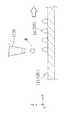
図1及び図3に示す三次元造形物の製造装置2000(以下、形成装置2000という)は、基台110と、基台110に備える駆動手段としての駆動装置111によって、図示するX,Y,Z方向の移動、あるいはZ軸を中心とする回転方向に駆動可能に備えられたステージ120を備えている。
そして、図1及び図2で表されるように、一方の端部が基台110に固定され、他方の端部に構成材料を吐出する構成材料吐出部1230を備えるヘッドユニット1400を複数保持するヘッドベース1100が保持固定される、ヘッドベース支持部130を備えている。
また、図3及び図4で表されるように、一方の端部が基台110に固定され、他方の端部に三次元造形物を支持する支持層形成用材料を吐出する支持層形成用材料吐出部1730を備えるヘッドユニット1900を複数保持するヘッドベース1600が保持固定される、ヘッドベース支持部730と、を備えている。
ここで、ヘッドベース1100と、ヘッドベース1600とは、XY平面において並列に設けられている。
なお、構成材料吐出部1230と支持層形成用材料吐出部1730とは同様の構成のものである。ただし、このような構成に限定されない。The three-dimensional model manufacturing apparatus 2000 (hereinafter referred to as the forming apparatus 2000) shown in FIGS. 1 and 3 includes the
Then, as shown in FIGS. 1 and 2, a plurality of
Further, as shown in FIGS. 3 and 4, one end is fixed to the
Here, the
The constituent
ステージ120上には、三次元造形物500が形成される過程での層501、502及び503が形成される。三次元造形物500の形成には、レーザーなどによる熱エネルギーの照射がなされるため、ステージ120の熱からの保護のため、耐熱性を有する試料プレート121を用いて、試料プレート121の上に三次元造形物500を形成してもよい。本実施形態の試料プレート121は頑丈で製造の容易な金属製のものである。しかしながら、試料プレート121としては、例えばセラミック板を用いることで、高い耐熱性を得ることができ、更に溶融(あるいは焼結されてもよい)される三次元造形物の構成材料との反応性も低く、三次元造形物500の変質を防止することができる。なお、図1及び図3では、説明の便宜上、層501、502及び503の3層を例示したが、所望の三次元造形物500の形状まで(図1及び図3中の層50nまで)積層される。
ここで、層501、502、503、・・・50nは、各々、支持層形成用材料吐出部1730から吐出される支持層形成用材料で形成される支持層300と、構成材料吐出部1230から吐出される構成材料で形成される構成層310と、で構成される。
Here, the
また、図2は、図1に示すヘッドベース1100を示すC部拡大概念図である。図2に示すように、ヘッドベース1100は、複数のヘッドユニット1400が保持されている。詳細は後述するが、1つのヘッドユニット1400は、構成材料供給装置1200に備える構成材料吐出部1230が保持治具1400aに保持されることで構成される。構成材料吐出部1230は、吐出ノズル1230aと、材料供給コントローラー1500によって吐出ノズル1230aから構成材料を吐出させる吐出駆動部1230bと、を備えている。 Further, FIG. 2 is an enlarged conceptual diagram of part C showing the
図4は、図3に示すヘッドベース1600を示すC’部拡大概念図である。図4に示すように、ヘッドベース1600は、複数のヘッドユニット1900が保持されている。ヘッドユニット1900は、支持層形成用材料供給装置1700に備える支持層形成用材料吐出部1730が保持治具1900aに保持されることで構成される。支持層形成用材料吐出部1730は、吐出ノズル1730aと、材料供給コントローラー1500によって吐出ノズル1730aから支持層形成用材料を吐出させる吐出駆動部1730bと、を備えている。また、支持層形成用材料として電磁波(紫外線など)により硬化可能な材料を使用した場合において該支持層形成用材料を硬化させるための、電磁波照射部1800をヘッドベース1600に備えている。また、支持層形成用材料に含まれるバインダーとして溶剤に溶解可能な材料を用いた場合においては、溶剤を除去し、該支持層形成用材料を硬化(バインダーによる結着)させるための、電磁波(赤外線)照射部1800をヘッドベース1600に備えてもよい。 FIG. 4 is an enlarged conceptual diagram of a C'section showing the
図1及び図2で表されるように、構成材料吐出部1230は、ヘッドベース1100に保持されるヘッドユニット1400それぞれに対応させた構成材料を収容した構成材料供給ユニット1210と供給チューブ1220により接続されている。そして、所定の構成材料が構成材料供給ユニット1210から構成材料吐出部1230に供給される。構成材料供給ユニット1210には、本実施形態に係る形成装置2000によって造形される三次元造形物500の構成材料が構成材料収容部1210aに収容され、個々の構成材料収容部1210aは、供給チューブ1220によって、個々の構成材料吐出部1230に接続されている。このように、個々の構成材料収容部1210aを備えることにより、ヘッドベース1100から、複数の異なる種類の材料を供給することができる。 As shown in FIGS. 1 and 2, the component
図3及び図4で表されるように、支持層形成用材料吐出部1730は、ヘッドベース1600に保持されるヘッドユニット1900それぞれに対応させた支持層形成用材料を収容した支持層形成用材料供給ユニット1710と供給チューブ1720により接続されている。そして、所定の支持層形成用材料が支持層形成用材料供給ユニット1710から支持層形成用材料吐出部1730に供給される。支持層形成用材料供給ユニット1710には、三次元造形物500を造形する際の支持層を構成する支持層形成用材料が支持層形成用材料収容部1710aに収容され、個々の支持層形成用材料収容部1710aは、供給チューブ1720によって、個々の支持層形成用材料吐出部1730に接続されている。このように、個々の支持層形成用材料収容部1710aを備えることにより、ヘッドベース1600から、複数の異なる種類の支持層形成用材料を供給することができる。
なお、本実施例の形成装置2000で使用される構成材料及び支持層形成用材料としての各々の三次元造形用ペーストについての詳細は後述する。As shown in FIGS. 3 and 4, the support layer forming
The details of the constituent materials used in the forming
形成装置2000には、図示しない、例えばパーソナルコンピューター等のデータ出力装置から出力される三次元造形物の造形用データに基づいて、上述したステージ120、構成材料供給装置1200に備える構成材料吐出部1230、並びに、支持層形成用材料供給装置1700に備える支持層形成用材料吐出部1730を制御する制御手段としての制御ユニット400を備えている。そして、制御ユニット400には、図示しないが、ステージ120及び構成材料吐出部1230が連携して駆動及び動作するよう制御し、ステージ120及び支持層形成用材料吐出部1730が連携して駆動及び動作するよう制御する制御部を備えている。 The forming
基台110に移動可能に備えられているステージ120は、制御ユニット400からの制御信号に基づき、ステージコントローラー410においてステージ120の移動開始と停止、移動方向、移動量、移動速度などを制御する信号が生成され、基台110に備える駆動装置111に送られ、図示するX,Y,Z方向にステージ120が移動する。ヘッドユニット1400に備える構成材料吐出部1230では、制御ユニット400からの制御信号に基づき、材料供給コントローラー1500において構成材料吐出部1230に備える吐出駆動部1230bにおける吐出ノズル1230aからの材料吐出量などを制御する信号が生成され、生成された信号により吐出ノズル1230aから所定量の構成材料が吐出される。
同様に、ヘッドユニット1900に備える支持層形成用材料吐出部1730では、制御ユニット400からの制御信号に基づき、材料供給コントローラー1500において支持層形成用材料吐出部1730に備える吐出駆動部1730bにおける吐出ノズル1730aからの材料吐出量などを制御する信号が生成され、生成された信号により吐出ノズル1730aから所定量の支持層形成用材料が吐出される。The
Similarly, in the support layer forming
次に、ヘッドユニット1400についてさらに詳細に説明する。なお、ヘッドユニット1900は、ヘッドユニット1400と同様の構成である。このため、ヘッドユニット1900についての詳細な構成の説明は省略する。
図5、並びに、図6〜図8は、ヘッドベース1100に複数保持されるヘッドユニット1400及び構成材料吐出部1230の保持形態の一例を示し、このうち図6〜図8は、図2に示す矢印D方向からのヘッドベース1100の外観図である。Next, the
5 and 6 to 8 show an example of a holding form of the
図5に示すように、ヘッドベース1100に複数のヘッドユニット1400が、図示しない固定手段によって保持されている。また、図6〜図8で表されるように、本実施形態に係る形成装置2000のヘッドベース1100では、図下方より第1列目のヘッドユニット1401、第2列目のヘッドユニット1402、第3列目のヘッドユニット1403、そして第4列目のヘッドユニット1404の、4ユニットが千鳥状(互い違い)に配置されたヘッドユニット1400を備えている。そして、図6で表されるように、ステージ120をヘッドベース1100に対してX方向に移動させながら各ヘッドユニット1400から構成材料を吐出させて構成層構成部50(構成層構成部50a、50b、50c及び50d)が形成される。構成層構成部50の形成手順については後述する。
なお、図示しないが、それぞれのヘッドユニット1401〜1404に備える構成材料吐出部1230は、吐出駆動部1230bを介して構成材料供給ユニット1210に供給チューブ1220で繋がれる構成となっている。As shown in FIG. 5, a plurality of
Although not shown, the component
図5に示すように、構成材料吐出部1230は吐出ノズル1230aから、ステージ120上に載置された試料プレート121上に向けて三次元造形物の構成材料である材料Mが吐出される。ヘッドユニット1401では、材料Mが液滴状で吐出される吐出形態を例示し、ヘッドユニット1402では、材料Mが連続体状で供給される吐出形態を例示している。材料Mの吐出形態は、液滴状であっても連続体状であっても、どちらでもよいが、本実施形態では材料Mは液滴状で吐出される形態により説明する。 As shown in FIG. 5, the component
吐出ノズル1230aから液滴状に吐出された材料Mは、略重力方向に飛翔し、試料プレート121上に着弾する。ステージ120は移動し、着弾した材料Mにより構成層構成部50が形成される。この構成層構成部50の集合体が、試料プレート121上に形成される三次元造形物500の構成層310(図1参照)として形成される。 The material M discharged in the form of droplets from the
次に、構成層構成部50の形成手順について、図6〜図8、並びに、図9及び図10を用いて説明する。
図6〜図8は、本実施形態のヘッドユニット1400の配置と、構成層構成部50の形成形態と、の関係を概念的に説明する平面図である。そして、図9及び図10は、構成層構成部50の形成形態を概念的に表す側面図である。Next, the procedure for forming the constituent layer
6 to 8 are plan views conceptually explaining the relationship between the arrangement of the
まず、ステージ120が+X方向に移動すると、複数の吐出ノズル1230aから材料Mが液滴状に吐出され、試料プレート121の所定の位置に材料Mが配置され、構成層構成部50が形成される。
より具体的には、まず、図9で表されるように、ステージ120を+X方向に移動させながら、複数の吐出ノズル1230aから試料プレート121の所定の位置に一定の間隔で材料Mを配置させる。First, when the
More specifically, first, as shown in FIG. 9, the material M is arranged at a predetermined position of the
次に、図10で表されるように、ステージ120を−X方向に移動させながら、一定の間隔で配置された材料Mの間を埋めるように新たに材料Mを配置させる。
ただし、ステージ120を+X方向に移動させながら、複数の吐出ノズル1230aから試料プレート121の所定の位置に材料Mが重なるように(間隔を空けないように)配置させる構成(ステージ120のX方向における往復移動で構成層構成部50を形成する構成ではなく、ステージ120のX方向における片側の移動のみで構成層構成部50を形成する構成)としても良い。Next, as shown in FIG. 10, while moving the
However, while moving the
上記のように構成層構成部50を形成することによって、図6で表されるような、各ヘッドユニット1401、1402、1403及び1404のX方向における1ライン分(Y方向における1ライン目)の構成層構成部50(構成層構成部50a、50b、50c及び50d)が形成される。 By forming the constituent layer
次に、各ヘッドユニット1401、1402、1403及び1404のY方向における2ライン目の構成層構成部50’(構成層構成部50a’、50b’、50c’及び50d’)を形成するため、−Y方向にヘッドベース1100を移動させる。移動量は、ノズル間のピッチをPとすると、P/n(nは自然数)ピッチ分だけ−Y方向に移動させる。本実施例ではnを3として説明する。
図9及び図10で表されるような、上記と同様な動作を行うことで、図7で表されるような、Y方向における2ライン目の構成層構成部50’(構成層構成部50a’、50b’、50c’及び50d’)が形成される。Next, in order to form the second line constituent layer constituents 50'(
By performing the same operation as described above as shown in FIGS. 9 and 10, the constituent layer constituent unit 50'(constituent layer
次に、各ヘッドユニット1401、1402、1403及び1404のY方向における3ライン目の構成層構成部50’’
(構成層構成部50a’’、50b’’、50c’’及び50d’’)を形成するため、−Y方向にヘッドベース1100を移動させる。移動量は、P/3ピッチ分だけ−Y方向に移動させる。
そして、図9及び図10で表されるような、上記と同様な動作を行うことで、図8で表されるような、Y方向における3ライン目の構成層構成部50’’
(構成層構成部50a’’、50b’’、50c’’及び50d’’)が形成され、構成層310を得ることができる。Next, the constituent layer constituent unit 50'' of the third line in the Y direction of each
The
Then, by performing the same operation as described above as shown in FIGS. 9 and 10, the constituent layer constituent unit 50'' of the third line in the Y direction as shown in FIG. 8 is performed.
(Constructive layer
また、構成材料吐出部1230から吐出される材料Mを、ヘッドユニット1401、1402、1403、1404のいずれか1ユニット、あるいは2ユニット以上からその他ヘッドユニットと異なる構成材料を吐出供給することもできる。従って、本実施形態に係る形成装置2000を用いることによって、異種材料から形成される三次元造形物を得ることができる。 Further, the material M discharged from the component
なお、第1層目の層501において、上述したように構成層310を形成する前或いは後に、支持層形成用材料吐出部1730から支持層形成用材料を吐出させて、同様の方法で、支持層300を形成することができる。そして、層501に積層させて層502、503、・・・50nを形成する際にも、同様に、構成層310及び支持層300を形成することができる。なお、支持層300は、支持層形成用材料の種類に応じて、電磁波照射部1800を用いて硬化することなどが可能である。 In the
上述の本実施形態に係る形成装置2000が備えるヘッドユニット1400及び1900の数及び配列は、上述した数及び配列に限定されない。図11及び図12に、その例として、ヘッドベース1100に配置されるヘッドユニット1400の、その他の配置の例を模式図的に示す。 The number and arrangement of the
図11は、ヘッドベース1100にヘッドユニット1400をX軸方向に複数、並列させた形態を示す。図12は、ヘッドベース1100にヘッドユニット1400を格子状に配列させた形態を示す。なお、いずれも配列されるヘッドユニットの数は、図示の例に限定されない。 FIG. 11 shows a form in which a plurality of
次に、本実施例の構成材料及び支持層形成用材料としての各々の三次元造形用ペーストについて詳細に説明する。
構成材料及び支持層形成用材料としては、例えばマグネシウム(Mg)、鉄(Fe)、コバルト(Co)やクロム(Cr)、アルミニウム(Al)、チタン(Ti)、銅(Cu)、ニッケル(Ni)の単体粉末、もしくはこれらの金属を1つ以上含む合金(マルエージング鋼、ステンレス、コバルトクロムモリブデン、チタニウム合金、ニッケル合金、アルミニウム合金、コバルト合金、コバルトクロム合金)などの混合粉末を、溶剤と、バインダーとを含むペースト状の混合材料にして用いることが可能である。
また、ポリアミド、ポリアセタール、ポリカーボネート、変性ポリフェニレンエーテル、ポリブチレンテレフタレート、ポリエチレンテレフタレートなどの汎用エンジニアリングプラスチックを用いることが可能である。その他、ポリサルフォン、ポリエーテルサルフォン、ポリフェニレンサルファイド、ポリアリレート、ポリイミド、ポリアミドイミド、ポリエーテルイミド、ポリエーテルエーテルケトンなどのエンジニアリングプラスチック(樹脂)も用いることが可能である。
このように、構成材料及び支持層形成用材料に特に限定はなく、上記金属以外の金属やセラミックスや樹脂等も使用可能である。また、二酸化ケイ素、二酸化チタン、酸化アルミニウム、酸化ジルコニウムなどを好ましく使用可能である。
さらには、セルロースなどの繊維も用いることが可能である。Next, each of the constituent materials of this example and the three-dimensional modeling paste as the material for forming the support layer will be described in detail.
Examples of the constituent material and the material for forming the support layer include magnesium (Mg), iron (Fe), cobalt (Co), chromium (Cr), aluminum (Al), titanium (Ti), copper (Cu), and nickel (Ni). ), Or a mixed powder such as an alloy containing one or more of these metals (malaging steel, stainless steel, cobalt-chromium molybdenum, titanium alloy, nickel alloy, aluminum alloy, cobalt alloy, cobalt-chromium alloy) as a solvent. , Can be used as a paste-like mixed material containing a binder.
Further, general-purpose engineering plastics such as polyamide, polyacetal, polycarbonate, modified polyphenylene ether, polybutylene terephthalate, and polyethylene terephthalate can be used. In addition, engineering plastics (resins) such as polysulfone, polyethersulfone, polyphenylene sulfide, polyarylate, polyimide, polyamideimide, polyetherimide, and polyetheretherketone can also be used.
As described above, the constituent material and the material for forming the support layer are not particularly limited, and metals other than the above metals, ceramics, resins and the like can also be used. Further, silicon dioxide, titanium dioxide, aluminum oxide, zirconium oxide and the like can be preferably used.
Furthermore, fibers such as cellulose can also be used.
溶剤としては、例えば、水;エチレングリコールモノメチルエーテル、エチレングリコールモノエチルエーテル、プロピレングリコールモノメチルエーテル、プロピレングリコールモノエチルエーテル等の(ポリ)アルキレングリコールモノアルキルエーテル類;酢酸エチル、酢酸n−プロピル、酢酸iso−プロピル、酢酸n−ブチル、酢酸iso−ブチル等の酢酸エステル類;ベンゼン、トルエン、キシレン等の芳香族炭化水素類;メチルエチルケトン、アセトン、メチルイソブチルケトン、エチル−n−ブチルケトン、ジイソプロピルケトン、アセチルアセトン等のケトン類;エタノール、プロパノール、ブタノール等のアルコール類;テトラアルキルアンモニウムアセテート類;ジメチルスルホキシド、ジエチルスルホキシド等のスルホキシド系溶剤;ピリジン、γ−ピコリン、2,6−ルチジン等のピリジン系溶剤;テトラアルキルアンモニウムアセテート(例えば、テトラブチルアンモニウムアセテート等)等のイオン液体等が挙げられ、これらから選択される1種または2種以上を組み合わせて用いることができる。
バインダーとしては、例えば、アクリル樹脂、エポキシ樹脂、シリコーン樹脂、セルロース系樹脂或いはその他の合成樹脂又はPLA(ポリ乳酸)、PA(ポリアミド)、PPS(ポリフェニレンサルファイド)或いはその他の熱可塑性樹脂である。また、紫外線の照射により重合する紫外線硬化樹脂をバインダーに用いてもよい。Examples of the solvent include water; (poly) alkylene glycol monoalkyl ethers such as ethylene glycol monomethyl ether, ethylene glycol monoethyl ether, propylene glycol monomethyl ether, and propylene glycol monoethyl ether; ethyl acetate, n-propyl acetate, and acetate. Acetate esters such as iso-propyl, n-butyl acetate, iso-butyl acetate; aromatic hydrocarbons such as benzene, toluene and xylene; methyl ethyl ketone, acetone, methyl isobutyl ketone, ethyl-n-butyl ketone, diisopropyl ketone, acetyl acetone Ketones such as; alcohols such as ethanol, propanol and butanol; tetraalkylammonium acetates; sulfoxide solvents such as dimethyl sulfoxide and diethyl sulfoxide; pyridine solvents such as pyridine, γ-picolin and 2,6-rutidine; tetra Examples thereof include ionic liquids such as alkylammonium acetate (for example, tetrabutylammonium acetate), and one or a combination of two or more selected from these can be used.
Examples of the binder include acrylic resin, epoxy resin, silicone resin, cellulose resin or other synthetic resin, PLA (polylactic acid), PA (polyamide), PPS (polyphenylene sulfide) or other thermoplastic resin. Further, an ultraviolet curable resin that polymerizes by irradiation with ultraviolet rays may be used as the binder.
ここで、本実施例の支持層形成用材料としての三次元造形用ペーストについてまとめると、本実施例の支持層形成用材料としての三次元造形用ペーストは、三次元造形物の構成領域に対応する構成層310と該構成層310に接し該構成層310を支持する支持層300とを形成して三次元造形物を製造する際に使用される、該支持層300の形成用の三次元造形用ペーストである。
そして、溶媒と該溶媒に可溶なバインダーと支持層形成用第1粒子と該支持層形成用第1粒子の焼結温度よりも低い分解温度の樹脂粒子(材料)とを含有する。なお、樹脂粒子としては上記で挙げたポリアミド(例えばナイロン12やナイロン66など)、ポリイミド、ポリアミドイミドなどの粒子を好ましく使用でき、支持層形成用第1粒子としては上記で挙げた金属やセラミックスなどの粒子を好ましく使用できる。
また、本実施例の支持層形成用材料としての三次元造形用ペーストは、支持層形成用第1粒子と樹脂粒子の合計の体積を100%として樹脂粒子を20%以上60%以下含有する。
支持層300を形成する際に本実施例の三次元造形用ペーストを使用することで、三次元造形物の形状が完成した後にそれを焼結させる際、焼結温度を支持層形成用第1粒子の焼結温度よりも低く樹脂粒子の分解温度よりも高くすることにより、樹脂粒子を揮発(昇華)させその領域に支持層形成用第1粒子を移動させることができる。すなわち、三次元造形物の焼結に伴って支持層300の体積を縮小させることができる。したがって、構成層310の焼結に伴う体積変化(収縮)に対応して支持層300が形状変化(収縮)し、支持層300は構成層310の焼結に伴う収縮の妨げにならないため、三次元造形物の焼結体が変形することを抑制でき、高精度な三次元造形物を製造することができる。
なお、樹脂粒子が20%未満であると三次元造形物の焼結に伴う支持層300の収縮が十分でない場合が発生し、樹脂粒子が60%を超えると三次元造形物の焼結に伴う支持層300の形状維持が不十分(構成層310が焼結する前に支持層300が崩れる)な場合が発生する。
また、支持層形成用材料としての三次元造形用ペーストは、支持層形成用第1粒子と樹脂粒子の合計の体積を100%として樹脂粒子を25%以上55%以下の体積で含有するものが特に好ましい。Here, to summarize the three-dimensional modeling paste as the support layer forming material of this example, the three-dimensional modeling paste as the support layer forming material of this example corresponds to the constituent area of the three-dimensional modeled object. A three-dimensional modeling for forming the supporting
Then, it contains a solvent, a binder soluble in the solvent, the first particles for forming the support layer, and the resin particles (material) having a decomposition temperature lower than the sintering temperature of the first particles for forming the support layer. As the resin particles, the above-mentioned particles such as polyamide (for example, nylon 12 and nylon 66), polyimide, and polyamide-imide can be preferably used, and the first particles for forming the support layer include the above-mentioned metals and ceramics. Particles can be preferably used.
Further, the three-dimensional modeling paste as the material for forming the support layer of this example contains 20% or more and 60% or less of the resin particles, with the total volume of the first particles for forming the support layer and the resin particles as 100%.
By using the three-dimensional modeling paste of this embodiment when forming the
If the resin particles are less than 20%, the shrinkage of the
Further, the three-dimensional modeling paste as the material for forming the support layer contains the resin particles in a volume of 25% or more and 55% or less, with the total volume of the first particles for forming the support layer and the resin particles as 100%. Especially preferable.
ここで、三次元造形用ペーストが支持層形成用第1粒子と樹脂粒子の合計の体積を100%として樹脂粒子を25%以上55%以下の体積で含有するか否かの確認は、例えば、以下のように行うことができる。
まず、遠心分離を行い、支持層形成用第1粒子と樹脂粒子を分離し、それぞれの重量を測定する。ここで、該それぞれの比重から体積が求められる。
そして、容器いっぱいに液体を満たし、支持層形成用第1粒子を沈めたときに溢れた液体の体積を測定することで支持層形成用第1粒子の体積が求められる。
なお、樹脂粒子についても同様にして体積が求められる。
このようにして得られた各々の体積から、樹脂粒子を25%以上55%以下の体積で含有するか否かを確認することができる。Here, it is confirmed, for example, whether or not the three-dimensional modeling paste contains the resin particles in a volume of 25% or more and 55% or less, with the total volume of the first particles for forming the support layer and the resin particles as 100%. It can be done as follows.
First, centrifugation is performed to separate the first particles for forming the support layer and the resin particles, and the weights of the respective particles are measured. Here, the volume is obtained from the specific gravity of each.
Then, the volume of the first particles for forming the support layer can be obtained by measuring the volume of the liquid that overflows when the container is filled with the liquid and the first particles for forming the support layer are submerged.
The volume of the resin particles can be obtained in the same manner.
From each volume thus obtained, it can be confirmed whether or not the resin particles are contained in a volume of 25% or more and 55% or less.
下記の表1で表されるように、三次元造形用ペーストが支持層形成用第1粒子と樹脂粒子の合計の体積を100%として樹脂粒子を25%以上55%以下の体積で含有させることで、支持層の形状維持、支持層の収縮、が優れた結果となり、総合評価が特に優れた結果となる。 As shown in Table 1 below, the three-dimensional modeling paste contains the resin particles in a volume of 25% or more and 55% or less, with the total volume of the first particles for forming the support layer and the resin particles as 100%. Therefore, the shape maintenance of the support layer and the shrinkage of the support layer are excellent results, and the comprehensive evaluation is particularly excellent.

ここで、樹脂粒子の平均粒径は、支持層形成用第1粒子の平均粒径以上であることが好ましい。樹脂粒子の平均粒径が支持層形成用第1粒子の平均粒径以上であれば、三次元造形物を焼結することで樹脂粒子が揮発して生じる領域に、支持層形成用第1粒子を効率的に移動させることができ、三次元造形物の焼結に伴って支持層300の体積を効果的に縮小させることができるためである。
樹脂粒子の平均粒径は、例えば、1μm以上50μm以下のものを好ましく使用することができる。1μm未満では支持層形成用第1粒子を効率的に移動させることが困難な場合が多くなり、50μmを超えると吐出ノズル1730aからの吐出が困難な場合が多くなるからである。
また、樹脂粒子は、溶媒に含有させることによる膨潤率が5%以下であることが好ましい。
ここで、粒子の形状は、特に限定されず、球状、紡錘形状、針状、筒状、鱗片状等、いかなる形状であってもよく、また、不定形であってもよいが、球状であるのが好ましい。
なお、本発明において、平均粒径とは、体積基準の平均粒径を言い、例えば、サンプルをメタノールに添加し、超音波分散器で3分間分散した分散液をコールターカウンター法粒度分布測定器(COULTER ELECTRONICS INS製TA−II型)にて、50μmのアパチャーを用いて測定することにより求めることができる。Here, the average particle size of the resin particles is preferably equal to or larger than the average particle size of the first particles for forming the support layer. If the average particle size of the resin particles is equal to or greater than the average particle size of the first support layer forming particles, the first support layer forming particles are located in the region where the resin particles are volatilized by sintering the three-dimensional model. This is because the volume of the
As the average particle size of the resin particles, for example, those having a diameter of 1 μm or more and 50 μm or less can be preferably used. This is because if it is less than 1 μm, it is often difficult to efficiently move the first particles for forming the support layer, and if it exceeds 50 μm, it is often difficult to discharge from the
Further, the resin particles preferably have a swelling rate of 5% or less when contained in a solvent.
Here, the shape of the particles is not particularly limited, and may be any shape such as a spherical shape, a spindle shape, a needle shape, a tubular shape, a scale shape, or an irregular shape, but is spherical. Is preferable.
In the present invention, the average particle size means a volume-based average particle size. For example, a dispersion liquid obtained by adding a sample to methanol and dispersing it with an ultrasonic disperser for 3 minutes is used as a particle size distribution measuring device by the Coulter counter method. It can be obtained by measuring with a COULTER ELECTRONICS INS TA-II type) using an aperture of 50 μm.
次に、上述の本実施形態に係る形成装置2000を用いて行う三次元造形物の製造方法の一実施例について説明する。
図13〜図18は、形成装置2000を用いて行う三次元造形物の製造過程の一例を表す概略図である。このうち、図13〜図16は三次元造形物の製造過程を側面視で表しており、図17及び図18は三次元造形物の製造過程を平面視で表している。また、図17及び図18は、図15及び図16に対応している。Next, an example of a method for manufacturing a three-dimensional model performed by using the forming
13 to 18 are schematic views showing an example of a manufacturing process of a three-dimensional modeled object performed by using the forming
最初に、図13は、支持層形成用材料吐出部1730を使用して試料プレート121の上に第1層目の層501のうちの支持層300を形成した状態を表している。なお、本実施例においては、支持層形成用材料として、支持層形成用第1粒子としての平均粒径3μmのアルミナ(セラミックス)粒子48.5%の重量(全粒子に対して50.0%の体積)と、樹脂粒子としての平均粒径5μmのナイロン12(ポリアミド12)粒子12.7%の重量(全粒子に対して50.0%の体積)と、バインダーとしてのメタクリル系樹脂7.8%の重量と、溶媒としてのカルビトールアセテート系溶媒31.0%の重量と、を含む材料を使用している。なお、さらに紫外線硬化樹脂などを含有していてもよい。
ここで、図13は、支持層形成用材料吐出部1730から支持層形成用材料を吐出した状態を表している。First, FIG. 13 shows a state in which the
Here, FIG. 13 shows a state in which the material for forming the support layer is discharged from the
次に、図14は、構成材料吐出部1230を使用して試料プレート121の上に第1層目の層501のうちの構成層310を形成した状態を表している。なお、本実施例においては、構成材料として、金属粒子である平均粒径3μmのSUS316粒子85.0%の重量と、バインダーとしてのメタクリル系樹脂3.0%の重量と、溶媒としてのカルビトールアセテート系溶媒12.0%の重量と、を含む材料を使用している。 Next, FIG. 14 shows a state in which the
そして、図13で表される支持層300の形成及び図14で表される構成層310の形成を繰り返すことにより、図15及び図17で表されるように、三次元造形物の積層体を形成する。
ここで、図15及び図17で表されるように、本実施例の三次元造形物の積層体は無底の円筒形状をしており、構成層310で囲まれた部分は空間S(正確には、少なくとも2方向から構成層310に囲まれた空間S)を構成している。Then, by repeating the formation of the
Here, as shown in FIGS. 15 and 17, the laminated body of the three-dimensional model of this embodiment has a bottomless cylindrical shape, and the portion surrounded by the
そして、最後に、図15及び図17で表されるように形成された三次元造形物の積層体を、本実施形態に係る形成装置2000とは別体として設けられる恒温槽(加熱槽)で、加熱する(構成層310を焼結させて焼結部310’とする)。ここで、図16及び図18は、三次元造形物の積層体を焼結させた状態を表している。
図16及び図18においては、焼結部310’は金属粒子が焼結しており、加熱後の支持層300’はバインダー及び支持層形成用樹脂粒子などが加熱分解されて揮発し除去された領域(揮発した領域)にセラミックス粒子である支持層形成用第1粒子が入り込んだため、密度が減少している。そして、加熱後の支持層300’は、残った粒子がセラミックス粒子である支持層形成用第1粒子であるため、粒状(パウダー状)となっている。Finally, the laminated body of the three-dimensional shaped objects formed as shown in FIGS. 15 and 17 is placed in a constant temperature bath (heating tank) provided as a separate body from the forming
In FIGS. 16 and 18, metal particles are sintered in the sintered portion 310', and the binder, the resin particles for forming the support layer, and the like are thermally decomposed and volatilized and removed from the support layer 300'after heating. Since the first particles for forming the support layer, which are ceramic particles, have entered the region (volatilized region), the density is reduced. The support layer 300'after heating is granular (powder-like) because the remaining particles are the first particles for forming the support layer, which are ceramic particles.
ここで、図15と図16、図17と図18を比較すると明らかなように、構成層310を焼結させると、体積は低下する。
体積の低下(体積の収縮)について説明すると、焼結後の1方向の長さをL、焼結前の1方向の長さをL0、構成層310の粒子の充填率をA、焼結密度をBとすると、以下の式1で表される。
L3=L03×(A/B)…(式1)
すなわち、焼結後の1方向の長さLは、L0×(A/B)1/3で表されるように収縮する。Here, as is clear from comparing FIGS. 15 and 16 and FIGS. 17 and 18, when the
Explaining the decrease in volume (shrinkage of volume), the length in one direction after sintering is L, the length in one direction before sintering is L0 , the filling rate of particles in the
L3 = L03 × (A / B) ... (Equation 1)
That is, the length L in one direction after sintering shrinks as represented byL 0 × (A / B)1/3.
このように、三次元造形物の積層体は焼結させることにより収縮するので、焼結後に、空間Sにおける支持層300の体積の収縮率が三次元造形物の積層体の収縮率よりも低い場合、三次元造形物の積層体(構成層310)は歪んでしまう。このため、本実施例においては、焼結後に、空間Sにおける支持層300の体積の収縮率が三次元造形物の積層体の収縮率よりも高くなるように、支持層形成材料の成分及びその配合を決定している。 In this way, since the laminated body of the three-dimensional model is shrunk by sintering, the shrinkage rate of the volume of the
次に、上記形成装置2000を用いて行う三次元造形物の製造方法の一例についてフローチャートを用いて説明する。
ここで、図19は、本実施例に係る三次元造形物の製造方法のフローチャートである。Next, an example of a method for manufacturing a three-dimensional modeled object performed by using the forming
Here, FIG. 19 is a flowchart of a method for manufacturing a three-dimensional model according to the present embodiment.
図19で表されるように、本実施例の三次元造形物の製造方法においては、最初にステップS110で、三次元造形物のデータを取得する。詳細には、例えばパーソナルコンピューターにおいて実行されているアプリケーションプログラム等から、三次元造形物の形状を表すデータを取得する。 As shown in FIG. 19, in the method for manufacturing a three-dimensional model of the present embodiment, first, in step S110, data of the three-dimensional model is acquired. Specifically, for example, data representing the shape of a three-dimensional model is acquired from an application program executed on a personal computer or the like.
次に、ステップS120で、層毎のデータを作成する。詳細には、三次元造形物の形状を表すデータにおいて、Z方向の造形解像度に従ってスライスし、断面毎にビットマップデータ(断面データ)を生成する。
この際、生成されるビットマップデータは、三次元造形物の形成領域(構成層310)と三次元造形物の非形成領域(支持層300)とで区別されたデータになっている。Next, in step S120, data for each layer is created. Specifically, in the data representing the shape of the three-dimensional modeled object, slices are made according to the modeling resolution in the Z direction, and bitmap data (cross-section data) is generated for each cross-section.
At this time, the generated bitmap data is data that is distinguished between the formed region of the three-dimensional modeled object (constituent layer 310) and the non-formed region of the three-dimensional modeled object (support layer 300).
次に、ステップS130で、形成しようとする層のデータが、三次元造形物の非形成領域(支持層300)を形成するデータか三次元造形物の形成領域(構成層310)を形成するデータかを判断する。なお。この判断は制御ユニット400に備えられた制御部により行われる。
本ステップで、支持層300を形成するデータと判断された場合はステップS140に進み、構成層310を形成するデータと判断された場合はステップS150に進む。Next, in step S130, the data of the layer to be formed is the data that forms the non-forming region (support layer 300) of the three-dimensional model or the data that forms the formation region (constituent layer 310) of the three-dimensional model. To judge. In addition. This determination is made by the control unit provided in the
In this step, if it is determined that the data forms the
ステップS140では、支持層300を形成するデータに基づいて支持層形成用材料吐出部1730から支持層形成用材料を吐出することにより、支持層形成用材料を供給する。
そして、ステップS140で支持層形成用材料を吐出すると、支持層形成用材料に紫外線硬化樹脂など電磁波が照射されることにより硬化する樹脂が含有されている場合、ステップS160で、電磁波照射部1800から電磁波(紫外線)を照射(エネルギー付与)して該吐出された液滴(支持層300)を固めることができる。
なお、支持層形成用材料に電磁波が照射されることにより硬化する樹脂が含有されていない場合は、ステップS160をスキップすることができる。支持層形成用材料である三次元造形用ペーストの粘度が高い場合などには、支持層300を固めなくても焼結前において構成層310を確りと支持できるためである。In step S140, the support layer forming material is supplied by discharging the support layer forming material from the support layer forming
Then, when the material for forming the support layer is discharged in step S140, if the material for forming the support layer contains a resin that is cured by being irradiated with an electromagnetic wave such as an ultraviolet curable resin, in step S160, the electromagnetic
If the material for forming the support layer does not contain a resin that is cured by being irradiated with electromagnetic waves, step S160 can be skipped. This is because when the viscosity of the three-dimensional modeling paste, which is a material for forming the support layer, is high, the
一方、ステップS150では、構成材料吐出部1230から構成材料を吐出することにより、構成材料を供給する。 On the other hand, in step S150, the constituent material is supplied by discharging the constituent material from the constituent
そして、ステップS170により、ステップS120において生成された各層に対応するビットマップデータに基づく三次元造形物の積層体の造形が終了するまで、ステップS130からステップS170までが繰り返される。 Then, in step S170, steps S130 to S170 are repeated until the modeling of the laminated body of the three-dimensional modeled object based on the bitmap data corresponding to each layer generated in step S120 is completed.
そして、ステップS180により、不図示の恒温槽において、上記ステップで形成した三次元造形物の積層体を加熱する。詳細には、三次元造形物の形成領域(構成層310)を焼結し、周りの支持層300の樹脂粒子などを分解除去して(揮発させて)セラミックス粒子などの支持層形成用第1粒子で粒子化する。別の表現をすると、本ステップにおける焼結温度は、支持層形成用第1粒子の焼結温度よりも低く樹脂粒子の分解温度よりも高くしている。ここで、加熱後の支持層300’の体積収縮率は、加熱後の構成層310(焼結部310’)の体積収縮率よりも高くなる(空間Sに対応する加熱後の支持層300’の体積は焼結部310’の体積よりも小さくなる)。
そして、ステップS180の終了に伴い、本実施例の三次元造形物の製造方法を終了する。Then, in step S180, the laminated body of the three-dimensional model formed in the above step is heated in a constant temperature bath (not shown). Specifically, the first for forming a support layer such as ceramic particles by sintering the forming region (constituent layer 310) of the three-dimensional model and decomposing and removing (volatilizing) the resin particles of the surrounding
Then, with the end of step S180, the method for manufacturing the three-dimensional model of the present embodiment is completed.
上記のように、本実施例の三次元造形物の製造方法は、三次元造形物の構成領域に対応する構成層310を形成する構成層形成工程(ステップS150)と、構成層310に接し該構成層310を支持する支持層300を形成する支持層形成工程(ステップS140)と、前記構成層を焼結する焼結工程(ステップS180)と、を有する。
そして、支持層形成工程では、支持層300を、溶媒と該溶媒に可溶なバインダーと支持層形成用第1粒子と該支持層形成用第1粒子の焼結温度よりも低い分解温度の樹脂粒子とを含有し、支持層形成用第1粒子と樹脂粒子の合計の体積を基準として樹脂粒子を20体積%以上60体積%以下含有する、三次元造形用ペーストを用いて形成している。
そして、焼結工程における焼結温度は、支持層形成用第1粒子の焼結温度よりも低く樹脂粒子の分解温度よりも高くしている。
このように、本実施例の三次元造形物の製造方法では、支持層形成工程において支持層300を形成する際、溶媒と該溶媒に可溶なバインダーと支持層形成用第1粒子と該支持層形成用第1粒子の焼結温度よりも低い分解温度の樹脂粒子とを含有し、支持層形成用第1粒子と樹脂粒子の合計の体積を基準として樹脂粒子を20体積%以上60体積%以下含有する三次元造形用ペーストを使用する。そして、このような三次元造形用ペーストを使用し、焼結工程において焼結温度を支持層形成用第1粒子の焼結温度よりも低く樹脂粒子の分解温度よりも高くすることで、樹脂粒子を揮発させその領域に支持層形成用第1粒子を移動させることができる。すなわち、三次元造形物の焼結に伴って支持層300の体積を縮小させることができる。したがって、本実施例の三次元造形物の製造方法は、構成層310の焼結に伴う体積変化(収縮)に対応して支持層300が形状変化し、支持層300は構成層310の焼結に伴う収縮の妨げにならないため、三次元造形物の焼結体が変形することを抑制でき、高精度な三次元造形物を製造することができる。
なお、焼結工程における焼結温度が支持層形成用第1粒子の焼結温度よりも低く樹脂粒子(一般的に樹脂の焼結温度は数十℃〜数百℃)の分解温度よりも高くするようにするために、例えば、構成材料における三次元造形物を構成する粉末粒子を鉄合金(焼結温度:1300℃〜1350℃)などの金属粒子とし、支持層形成用第1粒子をアルミナ(焼結温度:約1600℃)などのセラミックス粒子とし、焼結工程における焼結温度を数百℃〜約1000℃などとすることができる。ただし、このような例に限定されない。As described above, the method for manufacturing the three-dimensional model of the present embodiment includes a constituent layer forming step (step S150) for forming the
Then, in the support layer forming step, the
The sintering temperature in the sintering step is lower than the sintering temperature of the first particles for forming the support layer and higher than the decomposition temperature of the resin particles.
As described above, in the method for producing the three-dimensional model of the present embodiment, when the
The sintering temperature in the sintering step is lower than the sintering temperature of the first particles for forming the support layer and higher than the decomposition temperature of the resin particles (generally, the sintering temperature of the resin is several tens to several hundreds of degrees Celsius). For example, the powder particles constituting the three-dimensional model in the constituent material are made of metal particles such as an iron alloy (sintering temperature: 1300 ° C. to 1350 ° C.), and the first particles for forming the support layer are alumina. Ceramic particles such as (sintering temperature: about 1600 ° C.) can be used, and the sintering temperature in the sintering step can be set to several hundred ° C. to about 1000 ° C. However, the present invention is not limited to such an example.
また、本実施例の形成装置2000においては、上記のように、支持層形成用材料吐出部1730は、ヘッドベース1600に保持されるヘッドユニット1900それぞれに対応させた支持層形成用材料を収容した支持層形成用材料供給ユニット1710と供給チューブ1720により接続されている。すなわち、本実施例の形成装置2000は、支持層形成用材料として異なる複数種類の三次元造形用ペーストを使用することができる。このため、本実施例の三次元造形物の製造方法では、支持層形成工程において、支持層形成用第1粒子に対する樹脂粒子の含有比率及び樹脂粒子の平均粒径の少なくとも一方が異なる複数種類の三次元造形用ペーストを使用することができる。したがって、構成層310において該構成層310の焼結に伴う体積変化にバラツキが有る場合でも、該バラツキに対応して適切な収縮率となる三次元造形用ペースト(支持層形成用材料)を使用できる。
詳細には、支持層形成用第1粒子に対する樹脂粒子の含有比率及び樹脂粒子の平均粒径の少なくとも一方を変えることで、三次元造形物の焼結に伴って樹脂粒子が揮発することにより形成される支持層300における空孔の大きさや体積などを変えることができる。そして、空孔の大きさや体積などを変えることで、三次元造形物の焼結に伴う支持層300の収縮率を構成層310の収縮率に対応するように適正化することができる。Further, in the forming
Specifically, by changing at least one of the content ratio of the resin particles to the first particles for forming the support layer and the average particle size of the resin particles, the resin particles are volatilized as the three-dimensional model is sintered. The size and volume of the pores in the
上記のようにして構成される三次元造形物の具体的な形状の例について説明する。
図20〜図24はその具体例を表す概略分解側面図であり、このうち、図20はX方向に延びる2枚の平板が1辺において合わさり斜面が形成された形状を表している。また、図21は、無底の2つの円筒が重ねあわされた形状を表している。また、図22は、有底の円筒形状で内径の異なる部分を有する形状を表している。また、図23は、図22の形状に対して配管に対応するトンネルPが構成された形状を表している。そして、図24は、ドーム状の形状を表している。
しかしながら、このような形状に限定されるわけではないことは、言うまでもない。An example of a specific shape of the three-dimensional model formed as described above will be described.
20 to 24 are schematic exploded side views showing a specific example thereof, and FIG. 20 shows a shape in which two flat plates extending in the X direction are combined on one side to form a slope. Further, FIG. 21 shows a shape in which two bottomless cylinders are overlapped with each other. Further, FIG. 22 shows a bottomed cylindrical shape having portions having different inner diameters. Further, FIG. 23 shows a shape in which a tunnel P corresponding to the pipe is formed with respect to the shape of FIG. 22. And FIG. 24 shows a dome-shaped shape.
However, it goes without saying that the shape is not limited to such a shape.
本発明は、上述の実施例に限られるものではなく、その趣旨を逸脱しない範囲において種々の構成で実現することができる。例えば、発明の概要の欄に記載した各形態中の技術的特徴に対応する実施例中の技術的特徴は、上述の課題の一部又は全部を解決するために、あるいは、上述の効果の一部又は全部を達成するために、適宜、差し替えや、組み合わせを行うことが可能である。また、その技術的特徴が本明細書中に必須なものとして説明されていなければ、適宜、削除することが可能である。 The present invention is not limited to the above-described embodiment, and can be realized with various configurations within a range not deviating from the gist thereof. For example, the technical features in the examples corresponding to the technical features in each form described in the column of the outline of the invention may be used to solve some or all of the above-mentioned problems, or one of the above-mentioned effects. It is possible to replace or combine as appropriate to achieve part or all. Further, if the technical feature is not described as essential in the present specification, it can be deleted as appropriate.
50、50a、50b、50c、50d…構成層構成部、110…基台、
111…駆動装置、120…ステージ、121…試料プレート、
130…ヘッドベース支持部、300、300’…支持層、310…構成層、
310’…焼結部、400…制御ユニット、410…ステージコントローラー、
500…三次元造形物、501、502及び503…層、
730…ヘッドベース支持部、1100…ヘッドベース、
1200…構成材料供給装置、1210…構成材料供給ユニット、
1210a…構成材料収容部、1220…供給チューブ、1230…構成材料吐出部、
1230a…吐出ノズル、1230b…吐出駆動部、1400…ヘッドユニット、
1400a…保持治具、
1401、1402、1403及び1404…ヘッドユニット、
1500…材料供給コントローラー、1600…ヘッドベース、
1700…支持層形成用材料供給装置、1710…支持層形成用材料供給ユニット、
1710a…支持層形成用材料収容部、1720…供給チューブ、
1730…支持層形成用材料吐出部、1730a…吐出ノズル、
1730b…吐出駆動部、1800…電磁波照射部、1900…ヘッドユニット、
1900a…保持治具、2000…形成装置(三次元造形物の製造装置)、
M…材料(構成材料)、P…トンネル、S…構成層310に囲まれた空間50, 50a, 50b, 50c, 50d ... Constructible sheaf component, 110 ... Base,
111 ... drive device, 120 ... stage, 121 ... sample plate,
130 ... head base support, 300, 300'... support layer, 310 ... constituent layer,
310'... sintered part, 400 ... control unit, 410 ... stage controller,
500 ... 3D objects, 501, 502 and 503 ... layers,
730 ... Head base support, 1100 ... Head base,
1200 ... Constituent material supply device, 1210 ... Constituent material supply unit,
1210a ... Constituent material storage unit, 1220 ... Supply tube, 1230 ... Constituent material discharge unit,
1230a ... Discharge nozzle, 1230b ... Discharge drive unit, 1400 ... Head unit,
1400a ... Holding jig,
1401, 1402, 1403 and 1404 ... Head unit,
1500 ... Material supply controller, 1600 ... Head base,
1700 ... Support layer forming material supply device, 1710 ... Support layer forming material supply unit,
1710a ... Material accommodating portion for forming a support layer, 1720 ... Supply tube,
1730 ... Material discharge part for forming support layer, 1730a ... Discharge nozzle,
1730b ... Discharge drive unit, 1800 ... Electromagnetic wave irradiation unit, 1900 ... Head unit,
1900a ... Holding jig, 2000 ... Forming device (manufacturing device for three-dimensional model),
M ... Material (constituent material), P ... Tunnel, S ... Space surrounded by
Claims (6)
Translated fromJapanese溶媒と該溶媒に可溶なバインダーと支持層形成用第1粒子と該支持層形成用第1粒子の焼結温度よりも低い分解温度の材料とを含有し、
前記支持層形成用第1粒子と前記材料の合計の体積を100%として前記材料を20%以上60%以下の体積で含有し、
前記材料は粒子であって、
前記粒子の平均粒径は、前記支持層形成用第1粒子の平均粒径以上であることを特徴とするペースト。A paste used in the manufacture of three-dimensional objects.
It contains a solvent, a binder soluble in the solvent, the first particles for forming the support layer, and a material having a decomposition temperature lower than the sintering temperature of the first particles for forming the support layer.
The material is contained in a volume of 20% or more and 60% or less, assuming that the total volume of the first particles for forming the support layer and the material is 100%.
The material is particles
A paste characterized in thatthe average particle size of the particles is equal to or larger than the average particle size of the first particles for forming a support layer.
前記材料は、樹脂であることを特徴とするペースト。In the three-dimensional modeling paste according to claim 1,
The material is a paste characterized by being a resin.
前記支持層形成工程では、前記支持層を、溶媒と該溶媒に可溶なバインダーと支持層形成用第1粒子と該支持層形成用第1粒子の焼結温度よりも低い分解温度の樹脂粒子とを含有し、前記支持層形成用第1粒子と前記樹脂粒子の合計の体積を100%として前記樹脂粒子の材料を20%以上60%以下の体積で含有する、ペーストを用いて形成し、
前記焼結工程における焼結温度は、前記支持層形成用第1粒子の焼結温度よりも低く前記樹脂粒子の分解温度よりも高いことを特徴とする三次元造形物の製造方法。A constituent layer forming step of forming a constituent layer corresponding to a constituent region of a three-dimensional model, a support layer forming step of forming a support layer in contact with the constituent layer and supporting the constituent layer, and sintering of the constituent layer. A method for manufacturing a three-dimensional model having a sintering process.
In the support layer forming step, the support layer is made of a solvent, a binder soluble in the solvent, the first particles for forming the support layer, and resin particles having a decomposition temperature lower than the sintering temperature of the first particles for forming the support layer. The resin particles are formed by using a paste containing, and the total volume of the first particles for forming the support layer and the resin particles is 100%, and the material of the resin particles is contained in a volume of 20% or more and 60% or less.
A method for producing a three-dimensional model, wherein the sintering temperature in the sintering step is lower than the sintering temperature of the first particles for forming the support layer and higher than the decomposition temperature of the resin particles.
前記樹脂粒子の平均粒径は、前記支持層形成用第1粒子の平均粒径以上であることを特徴とする三次元造形物の製造方法。In the method for manufacturing a three-dimensional model according toclaim 3,
A method for producing a three-dimensional model, wherein the average particle size of the resin particles is equal to or larger than the average particle size of the first particles for forming a support layer.
前記支持層形成工程では、前記支持層形成用第1粒子に対する前記樹脂粒子の含有比率及び前記樹脂粒子の平均粒径の少なくとも一方が異なる複数種類のペーストを使用することを特徴とする三次元造形物の製造方法。In the method for manufacturing a three-dimensional model according toclaim 3 or4.
In the support layer forming step, three-dimensional modeling is characterized in that a plurality of types of pastes in which at least one of the content ratio of the resin particles to the first particles for forming the support layer and the average particle size of the resin particles are different are used. Manufacturing method of things.
前記第1粒子と前記材料の合計の体積を100%として前記材料を20%以上60%以下の体積で含有し、
前記材料は粒子であって、
前記粒子の平均粒径は、前記支持層形成用第1粒子の平均粒径以上であることを特徴とするペースト。It contains a solvent, a binder soluble in the solvent, and a material having a decomposition temperature lower than the sintering temperature of the first particles and the first particles.
The material is contained in a volume of 20% or more and 60% or less, assuming that the total volume of the first particles and the material is 100%.
The material is particles
A paste characterized in thatthe average particle size of the particles is equal to or larger than the average particle size of the first particles for forming a support layer.
Priority Applications (4)
| Application Number | Priority Date | Filing Date | Title |
|---|---|---|---|
| JP2017041933AJP6855846B2 (en) | 2017-03-06 | 2017-03-06 | Manufacturing method of paste and 3D model |
| CN201810161897.4ACN108527854B (en) | 2017-03-06 | 2018-02-27 | Paste and method for producing three-dimensional shaped object |
| EP18159808.7AEP3372327B1 (en) | 2017-03-06 | 2018-03-02 | Paste and method for producing three-dimensional shaped article |
| US15/911,589US10730235B2 (en) | 2017-03-06 | 2018-03-05 | Paste and method for producing three-dimensional shaped article |
Applications Claiming Priority (1)
| Application Number | Priority Date | Filing Date | Title |
|---|---|---|---|
| JP2017041933AJP6855846B2 (en) | 2017-03-06 | 2017-03-06 | Manufacturing method of paste and 3D model |
Publications (2)
| Publication Number | Publication Date |
|---|---|
| JP2018144354A JP2018144354A (en) | 2018-09-20 |
| JP6855846B2true JP6855846B2 (en) | 2021-04-07 |
Family
ID=61563217
Family Applications (1)
| Application Number | Title | Priority Date | Filing Date |
|---|---|---|---|
| JP2017041933AActiveJP6855846B2 (en) | 2017-03-06 | 2017-03-06 | Manufacturing method of paste and 3D model |
Country Status (4)
| Country | Link |
|---|---|
| US (1) | US10730235B2 (en) |
| EP (1) | EP3372327B1 (en) |
| JP (1) | JP6855846B2 (en) |
| CN (1) | CN108527854B (en) |
Families Citing this family (14)
| Publication number | Priority date | Publication date | Assignee | Title |
|---|---|---|---|---|
| US11230053B2 (en) | 2016-01-21 | 2022-01-25 | 3M Innovative Properties Company | Additive processing of fluoropolymers |
| JP6718306B2 (en)* | 2016-05-20 | 2020-07-08 | 三菱日立パワーシステムズ株式会社 | Valve and steam turbine equipment |
| EP3612330A4 (en)* | 2017-04-20 | 2021-03-31 | Xjet Ltd. | SYSTEM AND METHOD FOR MANUFACTURING PRINTED ITEMS |
| WO2019018787A1 (en)* | 2017-07-21 | 2019-01-24 | Saint-Gobain Performance Plastics Corporation | Method of forming a three-dimensional body |
| JP7515816B2 (en)* | 2018-12-25 | 2024-07-16 | エルジー・ケム・リミテッド | Molding apparatus and method for manufacturing molded body |
| CN111409266A (en)* | 2019-01-06 | 2020-07-14 | 严铜 | Easily-stripped supporting material and 3D printer using same |
| US11787108B2 (en)* | 2019-01-10 | 2023-10-17 | Hewlett-Packard Development Company, L.P. | Three-dimensional printing |
| CN114025930B (en)* | 2019-05-07 | 2024-03-29 | 三全音科技有限公司 | Additive manufacturing recipes for three-dimensional objects containing sinterable materials |
| JP7380080B2 (en)* | 2019-10-25 | 2023-11-15 | セイコーエプソン株式会社 | Method for manufacturing metal objects with porous structure |
| CN110625941B (en)* | 2019-10-30 | 2021-09-10 | 苏师大半导体材料与设备研究院(邳州)有限公司 | Primary screening and powder collecting device for 3D intelligent manufacturing |
| CN111283185A (en)* | 2020-03-17 | 2020-06-16 | 丽水学院 | Low-cost stainless steel indirect additive manufacturing method |
| JP2021161492A (en)* | 2020-03-31 | 2021-10-11 | 株式会社リコー | Molding table and molding apparatus |
| EP4188676A1 (en)* | 2020-07-27 | 2023-06-07 | Stratasys Ltd. | Method and system for three-dimensional printing on fabric |
| DE102021204295A1 (en) | 2021-04-29 | 2022-11-03 | Robert Bosch Gesellschaft mit beschränkter Haftung | Gob applicator and method for producing molten metal gobs |
Family Cites Families (16)
| Publication number | Priority date | Publication date | Assignee | Title |
|---|---|---|---|---|
| GB8914023D0 (en)* | 1989-06-19 | 1989-08-09 | Alcan Int Ltd | Porous ceramic membrane method |
| US5204055A (en) | 1989-12-08 | 1993-04-20 | Massachusetts Institute Of Technology | Three-dimensional printing techniques |
| US7700016B2 (en)* | 2005-08-02 | 2010-04-20 | Solidscape, Inc. | Method and apparatus for fabricating three dimensional models |
| JP5668328B2 (en)* | 2010-05-26 | 2015-02-12 | セイコーエプソン株式会社 | Slurry for modeling and modeling method |
| EP2914433B1 (en)* | 2012-11-05 | 2018-03-28 | Stratasys Ltd. | System and method for direct inkjet printing of 3d objects |
| JP6057806B2 (en)* | 2013-03-27 | 2017-01-11 | 群栄化学工業株式会社 | COMPOSITE MATERIAL POWDER AND METHOD FOR PRODUCING MOLDED ARTICLE |
| EP3057776B1 (en)* | 2013-10-17 | 2020-03-18 | Xjet Ltd. | Support ink for three dimensional (3d) printing |
| JP6478212B2 (en) | 2013-10-24 | 2019-03-06 | 株式会社リコー | Three-dimensional structure modeling method and three-dimensional structure modeling apparatus |
| CN104710548B (en)* | 2014-01-03 | 2017-09-29 | 南京波斯塔新材料科技有限公司 | A kind of 3D printing core material |
| JP6387614B2 (en)* | 2014-01-09 | 2018-09-12 | セイコーエプソン株式会社 | Manufacturing method of three-dimensional structure and ink set |
| JP6390108B2 (en)* | 2014-02-07 | 2018-09-19 | セイコーエプソン株式会社 | Sintered modeling material, sintered modeling method, sintered model and sintered modeling apparatus |
| WO2015141032A1 (en)* | 2014-03-18 | 2015-09-24 | 株式会社 東芝 | Additive layer manufacturing device and method for manufacturing additive layer manufacturing article |
| JP2015208859A (en)* | 2014-04-23 | 2015-11-24 | セイコーエプソン株式会社 | Method for manufacturing three-dimensional molded article and three-dimensional molded article |
| JP2016182794A (en)* | 2015-03-26 | 2016-10-20 | セイコーエプソン株式会社 | Composition for three-dimensional molding, method for manufacturing three-dimensional molded object, and three-dimensional molded object |
| JP6676984B2 (en)* | 2016-01-29 | 2020-04-08 | セイコーエプソン株式会社 | Manufacturing method of three-dimensional objects |
| CN110312582A (en)* | 2016-12-14 | 2019-10-08 | 德仕托金属有限公司 | Material Systems for Additive Manufacturing |
- 2017
- 2017-03-06JPJP2017041933Apatent/JP6855846B2/enactiveActive
- 2018
- 2018-02-27CNCN201810161897.4Apatent/CN108527854B/enactiveActive
- 2018-03-02EPEP18159808.7Apatent/EP3372327B1/enactiveActive
- 2018-03-05USUS15/911,589patent/US10730235B2/enactiveActive
Also Published As
| Publication number | Publication date |
|---|---|
| US20180250877A1 (en) | 2018-09-06 |
| EP3372327B1 (en) | 2019-10-02 |
| JP2018144354A (en) | 2018-09-20 |
| US10730235B2 (en) | 2020-08-04 |
| CN108527854B (en) | 2020-09-29 |
| CN108527854A (en) | 2018-09-14 |
| EP3372327A1 (en) | 2018-09-12 |
Similar Documents
| Publication | Publication Date | Title |
|---|---|---|
| JP6855846B2 (en) | Manufacturing method of paste and 3D model | |
| JP6448004B2 (en) | Three-dimensional additive manufacturing apparatus and three-dimensional additive manufacturing method | |
| JP6676984B2 (en) | Manufacturing method of three-dimensional objects | |
| JP6669985B2 (en) | Manufacturing method of three-dimensional objects | |
| JP6981558B2 (en) | 3D modeling stage, 3D modeling equipment and 3D modeling method | |
| JP2021155851A (en) | Flowable composition set and flowable composition | |
| JP6826321B2 (en) | Modeling stage of 3D model, 3D model manufacturing device and 3D model manufacturing method | |
| JP2018051969A (en) | Three-dimensional structure manufacturing apparatus and three-dimensional structure manufacturing method | |
| JP6751252B2 (en) | Three-dimensional model manufacturing method and three-dimensional model manufacturing apparatus | |
| CN109483879B (en) | Manufacturing method of three-dimensional shaped object | |
| CN107825698B (en) | Three-dimensional modeling device, three-dimensional modeling method and storage medium | |
| JP6802517B2 (en) | Modeling stage of 3D model, 3D model manufacturing device and 3D model manufacturing method | |
| JP6950498B2 (en) | Manufacturing method of 3D model | |
| JP6924382B2 (en) | Manufacturing method of 3D model and manufacturing equipment of 3D model | |
| JP6924380B2 (en) | 3D model manufacturing equipment and 3D model manufacturing method | |
| JP2021008095A (en) | Manufacturing apparatus for three-dimensional molded article | |
| JP2018051964A (en) | Three-dimensional structure manufacturing apparatus and three-dimensional structure manufacturing method | |
| JP2017075369A (en) | Method for manufacturing three-dimensional molded article and apparatus for manufacturing three-dimensional molded article | |
| US11759856B2 (en) | Method for manufacturing three-dimensional shaped object | |
| JP2019099859A (en) | Method for manufacturing three-dimensional molded article | |
| JP2020192758A (en) | Material set and method for manufacturing three-dimensional object |
Legal Events
| Date | Code | Title | Description |
|---|---|---|---|
| A621 | Written request for application examination | Free format text:JAPANESE INTERMEDIATE CODE: A621 Effective date:20191212 | |
| A977 | Report on retrieval | Free format text:JAPANESE INTERMEDIATE CODE: A971007 Effective date:20201016 | |
| A131 | Notification of reasons for refusal | Free format text:JAPANESE INTERMEDIATE CODE: A131 Effective date:20201111 | |
| A521 | Request for written amendment filed | Free format text:JAPANESE INTERMEDIATE CODE: A523 Effective date:20201209 | |
| TRDD | Decision of grant or rejection written | ||
| A01 | Written decision to grant a patent or to grant a registration (utility model) | Free format text:JAPANESE INTERMEDIATE CODE: A01 Effective date:20210216 | |
| A61 | First payment of annual fees (during grant procedure) | Free format text:JAPANESE INTERMEDIATE CODE: A61 Effective date:20210301 | |
| R150 | Certificate of patent or registration of utility model | Ref document number:6855846 Country of ref document:JP Free format text:JAPANESE INTERMEDIATE CODE: R150 |