JP6853796B2 - Bottom and sleeper - Google Patents
Bottom and sleeperDownload PDFInfo
- Publication number
- JP6853796B2 JP6853796B2JP2018043632AJP2018043632AJP6853796B2JP 6853796 B2JP6853796 B2JP 6853796B2JP 2018043632 AJP2018043632 AJP 2018043632AJP 2018043632 AJP2018043632 AJP 2018043632AJP 6853796 B2JP6853796 B2JP 6853796B2
- Authority
- JP
- Japan
- Prior art keywords
- bottom member
- main body
- body frame
- frame
- fixing member
- Prior art date
- Legal status (The legal status is an assumption and is not a legal conclusion. Google has not performed a legal analysis and makes no representation as to the accuracy of the status listed.)
- Active
Links
- 241001669679EleotrisSpecies0.000titleclaimsdescription72
- 230000002093peripheral effectEffects0.000claimsdescription29
- NJPPVKZQTLUDBO-UHFFFAOYSA-NnovaluronChemical compoundC1=C(Cl)C(OC(F)(F)C(OC(F)(F)F)F)=CC=C1NC(=O)NC(=O)C1=C(F)C=CC=C1FNJPPVKZQTLUDBO-UHFFFAOYSA-N0.000claimsdescription18
- 238000004891communicationMethods0.000claimsdescription15
- 230000007246mechanismEffects0.000description31
- 210000002683footAnatomy0.000description27
- 230000003028elevating effectEffects0.000description21
- 210000002414legAnatomy0.000description16
- 210000003127kneeAnatomy0.000description12
- 238000005452bendingMethods0.000description5
- 230000003014reinforcing effectEffects0.000description5
- 239000000463materialSubstances0.000description4
- 229920003002synthetic resinPolymers0.000description4
- 239000000057synthetic resinSubstances0.000description4
- 230000000694effectsEffects0.000description3
- 239000002184metalSubstances0.000description3
- 230000004048modificationEffects0.000description3
- 238000012986modificationMethods0.000description3
- 239000000470constituentSubstances0.000description2
- 238000001746injection mouldingMethods0.000description2
- 238000004519manufacturing processMethods0.000description2
- 125000006850spacer groupChemical group0.000description2
- 238000003466weldingMethods0.000description2
- 125000002066L-histidyl groupChemical group[H]N1C([H])=NC(C([H])([H])[C@](C(=O)[*])([H])N([H])[H])=C1[H]0.000description1
- 239000007769metal materialSubstances0.000description1
- 230000000474nursing effectEffects0.000description1
- 230000000149penetrating effectEffects0.000description1
- 210000003371toeAnatomy0.000description1
Images


Landscapes
- Invalid Beds And Related Equipment (AREA)
Description
Translated fromJapanese本発明は、ボトム、及び寝台装置に関する。 The present invention relates to a bottom and a sleeper device.
従来から、寝台装置本体に取付けられるボトムとして、例えば下記特許文献1に示されるように、表裏面が上下方向を向き、合成樹脂材料により一体に形成され、固定部材により寝台装置に取付けられる構成が知られている。 Conventionally, as a bottom to be attached to the sleeper device main body, for example, as shown in Patent Document 1 below, the front and back surfaces are oriented in the vertical direction, and the bottom is integrally formed of a synthetic resin material and attached to the sleeper device by a fixing member. Are known.
しかしながら、前記従来のボトムにおいては、全体が合成樹脂材料により一体に形成されているので、例えばボトムの上面部分のみを寝台装置本体から取り外して清拭したい場合であっても、ボトム全体を寝台装置本体から取り外す必要があった。 However, since the entire bottom of the conventional bottom is integrally formed of a synthetic resin material, for example, even if it is desired to remove only the upper surface portion of the bottom from the main body of the sleeper device and wipe it clean, the entire bottom of the sleeper device can be wiped. It had to be removed from the body.
本発明は、前述した事情に鑑みてなされたものであって、寝台装置からボトムの一部を容易に取り外すことができるボトムを提供することを目的とする。 The present invention has been made in view of the above circumstances, and an object of the present invention is to provide a bottom in which a part of the bottom can be easily removed from the sleeper device.
前記課題を解決するために、本発明は以下の手段を提案している。
(1)本発明に係るボトムは、寝台装置の支持架台に取付けられる本体フレームと、表裏面が上下方向に向けられた状態で前記本体フレームの上面に載置されたボトム部材と、前記ボトム部材を前記本体フレームに離脱自在に固定する固定部材と、を備え、前記固定部材は、前記ボトム部材の上面に配設されていることを特徴とする。In order to solve the above problems, the present invention proposes the following means.
(1) The bottom according to the present invention includes a main body frame attached to a support frame of a sleeper device, a bottom member mounted on the upper surface of the main body frame with the front and back surfaces facing in the vertical direction, and the bottom member. The body is provided with a fixing member that is detachably fixed to the main body frame, and the fixing member is disposed on the upper surface of the bottom member.
この発明では、ボトムが、寝台装置の支持架台に取付けられる本体フレームと、本体フレームの上面に載置されたボトム部材と、を備えている。このため、ボトム部材の上面を例えば清拭する際等に、ボトムのうち、上面を有するボトム部材のみを本体フレームから取り外すことが可能になり、優れた取扱性を具備させることができる。
また、固定部材が、ボトム部材の上面に配設されているので、ボトム部材の上方から固定部材を操作することが可能になり、この操作時に、例えば工具をボトム部材の下方から回り込ませたり、他の部材間の隙間に進入させたりする等の必要がなく、ボトム部材を本体フレームに容易に着脱することができる。
また、例えば本体フレームをパイプ等により形成し、ボトム部材を板金等により形成した場合には、ボトムを射出成形により一体に形成するような場合と比べて、金型製作等の初期費用を抑えることができ、ボトムを安価に製造することができる。In the present invention, the bottom includes a main body frame attached to the support base of the sleeper device, and a bottom member mounted on the upper surface of the main body frame. Therefore, when the upper surface of the bottom member is wiped, for example, only the bottom member having the upper surface can be removed from the main body frame, and excellent handleability can be provided.
Further, since the fixing member is arranged on the upper surface of the bottom member, the fixing member can be operated from above the bottom member, and at the time of this operation, for example, a tool can be wrapped around from below the bottom member. The bottom member can be easily attached to and detached from the main body frame without having to enter the gap between other members.
Further, for example, when the main body frame is formed of a pipe or the like and the bottom member is formed of a sheet metal or the like, the initial cost of mold production or the like can be suppressed as compared with the case where the bottom is integrally formed by injection molding or the like. And the bottom can be manufactured at low cost.
(2)上記(1)に係るボトムであって、前記ボトム部材は、上面視で4つの辺部を有する矩形状を呈し、前記固定部材は、前記4つの辺部のうちの少なくとも1つに配設され、前記4つの辺部のうち、前記固定部材が配設された辺部と異なる辺部には、前記本体フレームの下面に係止する係止部が配設されてもよい。 (2) The bottom according to (1), the bottom member has a rectangular shape having four sides when viewed from above, and the fixing member is formed on at least one of the four sides. Of the four side portions that are arranged, a locking portion that locks to the lower surface of the main body frame may be arranged on a side portion that is different from the side portion on which the fixing member is arranged.
この場合、ボトム部材の外周縁部における4つの辺部のうちの少なくとも1つの辺部に固定部材が配設されるとともに、他の辺部に、本体フレームの下面に、本体フレームの下面に係止する係止部が配設されている。このため、ボトム部材に、ボトム部材を本体フレームから持ち上げるような外力が加えられた際に、係止部が本体フレームの下面に係止することとなる。これにより、ボトム部材に加えられたこのような外力を、固定部材だけでなく、係止部によっても受け止めさせることができる。その結果、ボトム部材のうち、固定部材の周囲に位置する部分に大きな力がかかるのを抑制することが可能になり、ボトム部材に局所的な変形が生じるのを抑えることができる。 In this case, the fixing member is arranged on at least one side of the four sides on the outer peripheral edge of the bottom member, and is engaged with the other side, the lower surface of the main body frame, and the lower surface of the main body frame. A locking portion for stopping is provided. Therefore, when an external force such as lifting the bottom member from the main body frame is applied to the bottom member, the locking portion is locked to the lower surface of the main body frame. As a result, such an external force applied to the bottom member can be received not only by the fixing member but also by the locking portion. As a result, it is possible to suppress the application of a large force to the portion of the bottom member located around the fixing member, and it is possible to suppress the occurrence of local deformation of the bottom member.
(3)上記(2)に係るボトムであって、前記4つの辺部のうち、前記固定部材が配設された辺部と、前記係止部が配設された辺部と、は、互いに対向してもよい。 (3) Of the four side portions of the bottom according to (2) above, the side portion on which the fixing member is arranged and the side portion on which the locking portion is arranged are mutually exclusive. They may face each other.
この場合、係止部が、ボトム部材の辺部のうち、固定部材が配設された辺部から最も離れた辺部に配設されることになるので、固定部材と係止部との間の距離を大きく確保することできる。このため、ボトム部材のうち、固定部材が配設された辺部から最も離れた辺部に、ボトム部材を本体フレームから持ち上げるような外力が加えられた際には、固定部材周りに発生する回転モーメントを係止部が受けることで、係止部に生じる反力を小さくすることが可能になる。これにより、確実にボトム部材を本体フレームに係止することができる。 In this case, since the locking portion is arranged on the side portion of the bottom member that is farthest from the side portion on which the fixing member is arranged, between the fixing member and the locking portion. A large distance can be secured. Therefore, when an external force for lifting the bottom member from the main body frame is applied to the side portion of the bottom member farthest from the side portion on which the fixing member is arranged, the rotation generated around the fixing member is applied. When the locking portion receives the moment, the reaction force generated in the locking portion can be reduced. As a result, the bottom member can be securely locked to the main body frame.
(4)上記(2)又は(3)に係るボトムであって、前記4つの辺部のうち、前記係止部が配設された辺部には、下方に向けて延び、下端部に前記係止部が形成された折曲部が配設され、前記ボトム部材、前記折曲部、及び前記係止部は、互いに一体に形成されてもよい。 (4) The bottom according to (2) or (3), of the four side portions, the side portion on which the locking portion is arranged extends downward, and the lower end portion has the said. A bent portion in which a locking portion is formed may be arranged, and the bottom member, the bent portion, and the locking portion may be integrally formed with each other.
この場合には、折曲部及び係止部を、例えばボトム部材に曲げ加工を施すことにより形成することができ、ボトム部材を安価に製造することができる。 In this case, the bent portion and the locking portion can be formed by, for example, bending the bottom member, and the bottom member can be manufactured at low cost.
(5)上記(1)から(4)のいずれか1つに係るボトムであって、前記本体フレーム及び前記ボトム部材には、上下方向に互いに連通する連通孔が各別に形成され、前記固定部材は、上下方向に延びる軸体と、前記軸体の上端部に配設されたフランジ部と、を備え、前記固定部材は、前記フランジ部が前記ボトム部材の上面に配置され、前記軸体が前記本体フレーム及び前記ボトム部材の各連通孔に一体に挿入された状態で、前記ボトム部材を、前記本体フレームに固定してもよい。 (5) The bottom according to any one of (1) to (4) above, the main body frame and the bottom member are each separately formed with communication holes communicating with each other in the vertical direction, and the fixing member. Includes a shaft body extending in the vertical direction and a flange portion arranged at the upper end portion of the shaft body, and the fixing member has the flange portion arranged on the upper surface of the bottom member, and the shaft body has the shaft body. The bottom member may be fixed to the main body frame while being integrally inserted into the communication holes of the main body frame and the bottom member.
この場合、軸体を、本体フレーム及びボトム部材に、各別に形成された連通孔に一体に挿入するとともに、フランジ部をボトム部材の上面に配置することで、ボトム部材を本体フレームに固定することができる。これにより、ボトム部材を本体フレームに着脱する際に、ボトム部材の上面から上方に突出したフランジ部を操作することが可能になり、この着脱操作を容易に行うことができる。 In this case, the shaft body is integrally inserted into the main body frame and the bottom member into the communication holes formed separately, and the flange portion is arranged on the upper surface of the bottom member to fix the bottom member to the main body frame. Can be done. As a result, when attaching / detaching the bottom member to / from the main body frame, it is possible to operate the flange portion protruding upward from the upper surface of the bottom member, and this attaching / detaching operation can be easily performed.
(6)上記(1)から(5)のいずれか1つに係るボトムであって、前記フランジ部は、前記ボトム部材の上面に載置される下面と、前記下面の外周縁から内側に向かうに従い漸次、上方に向けて延びる突曲面と、を備えてもよい。 (6) A bottom according to any one of (1) to (5) above, the flange portion is a lower surface mounted on the upper surface of the bottom member and faces inward from the outer peripheral edge of the lower surface. It may be provided with a protruding curved surface that gradually extends upward according to the above.
この場合、ボトム部材の上面に載置される固定部材の下面の外周縁部から、突曲面が接続されているので、固定部材におけるフランジ部の外周縁と、ボトム部材の上面と、の間に段差が生ずるのを抑制することが可能になり、このような段差に物などが引っ掛かるのを抑制することができる。 In this case, since the protruding curved surface is connected from the outer peripheral edge portion of the lower surface of the fixing member mounted on the upper surface of the bottom member, the outer peripheral edge of the flange portion of the fixing member and the upper surface of the bottom member are between. It is possible to suppress the occurrence of a step, and it is possible to prevent an object or the like from being caught in such a step.
(7)本発明に係る寝台装置は、ボトムと、前記ボトムが取付けられた支持架台と、を備える寝台装置であって、前記ボトムは、上記(1)から(6)のいずれか1つに係るボトムであることを特徴とする。 (7) The sleeper device according to the present invention is a sleeper device including a bottom and a support pedestal to which the bottom is attached, and the bottom is any one of (1) to (6) above. It is characterized by being such a bottom.
この場合、寝台装置が上記のボトムを備えているので、寝台装置において上記の作用効果を奏功させることができる。 In this case, since the sleeper device has the above-mentioned bottom, the above-mentioned action and effect can be achieved in the sleeper device.
(8)本発明に係る寝台装置は、上記(7)に係る寝台装置であって、前記ボトムは、前記ボトム部材の表裏面が、前後方向に向かうに従い漸次、上下方向に延びるように水平方向に対して傾斜可能に、前記支持架台に支持され、前記ボトム部材は、上面視で前後方向に延びる2つの辺部、及び左右方向に延びる2つの辺部を有する矩形状を呈し、前記左右方向に延びる2つの辺部のうち、前記ボトム部材が傾斜した際に上方に位置する辺部には、前記本体フレームの下面に係止する係止部が配設されてもよい。 (8) The sleeper device according to the present invention is the sleeper device according to the above (7), and the bottom is in the horizontal direction so that the front and back surfaces of the bottom member gradually extend in the vertical direction as the front and rear directions are directed. The bottom member is supported by the support pedestal so as to be inclined with respect to the above, and the bottom member has a rectangular shape having two side portions extending in the front-rear direction and two side portions extending in the left-right direction in a top view, and the bottom member has a rectangular shape extending in the left-right direction. Of the two side portions extending in the direction of the above, a locking portion that locks to the lower surface of the main body frame may be provided on the side portion that is located upward when the bottom member is tilted.
この場合、係止部が、ボトム部材の外周縁部における2つの左右方向に延びる辺部のうち、ボトム部材の表裏面を水平方向に対して傾斜させた際に、上方に位置する辺部に配設されている。このため、ボトム部材の表裏面が水平方向に対して傾斜したことにより、本体フレームの上面で支えることができないボトム部材の自重を、固定部材だけでなく、係止部にも受け止めさせることができ、固定部材にかかる負荷を抑えることができる。 In this case, of the two laterally extending side portions of the outer peripheral edge portion of the bottom member, the locking portion is located on the side portion located above when the front and back surfaces of the bottom member are inclined with respect to the horizontal direction. It is arranged. Therefore, since the front and back surfaces of the bottom member are inclined with respect to the horizontal direction, the weight of the bottom member, which cannot be supported by the upper surface of the main body frame, can be received not only by the fixing member but also by the locking portion. , The load applied to the fixing member can be suppressed.
本発明によれば、寝台装置からボトムの一部を容易に取り外すことができる。 According to the present invention, a part of the bottom can be easily removed from the sleeper device.
本発明の一実施形態に係る寝台装置10を、図1から図13に基づいて以下に説明する。
寝台装置10は、例えば、医療環境下(介護環境下を含む)において、一般床ベッドやICUベッド等として利用することができる。図1から図13において、矢印Hは人(使用者)が寝る際に頭側Hとなる向きを示し、また矢印Fは人が寝る際に足側Fとなる向きを示している。以下の説明においては、矢印H、Fの方向である前後方向Xに対して直交する水平方向を左右方向Yと言う場合が有る。前後方向X及び左右方向Yは、いずれも水平方向に沿う方向であるとともに、互いに直交する方向である。The
The
図1から図6に示すように、寝台装置10は、寝台装置本体17と、寝台装置本体17の外周縁部に複数立設された壁状部材18と、を備えている。寝台装置本体17は、寝台11と、支持架台12と、寝台用オプション15と、駆動機構16と、を備え、壁状部材18は、柵体13と、ボード14と、を備えている。寝台装置10は、電力を動力源とするいわゆる電動ベッドである。
寝台11は、上面視した場合に左右方向Yよりも前後方向Xに長い。寝台11の長手方向は前後方向Xとされ、寝台11の短手方向は左右方向Yとなっている。寝台11上には、図13に示すようにマットレス80が配置される。寝台11には、マットレス80を介して使用者が横たわる。As shown in FIGS. 1 to 6, the
The sleeper 11 is longer in the front-rear direction X than in the left-right direction Y when viewed from above. The longitudinal direction of the sleeper 11 is the front-rear direction X, and the lateral direction of the sleeper 11 is the left-right direction Y. A mattress 80 is arranged on the bed 11 as shown in FIG. The user lies on the bed 11 via the mattress 80.
寝台11は、背ボトム21と、腰ボトム22と、脚ボトム23と、を備えている。これらの背ボトム21、腰ボトム22及び脚ボトム23は、頭側Hから足側Fに向けてこの順に並んでいる。背ボトム21は、使用者の背を支える。腰ボトム22は、使用者の腰を支える。脚ボトム23は、使用者の脚を支える。
脚ボトム23は、膝ボトム24と、足ボトム25と、を備えている。これらの膝ボトム24及び足ボトム25は、頭側Hから足側Fに向けてこの順に並んでいる。膝ボトム24は、使用者の膝から腰を支える。足ボトム25は、使用者の膝から足先を支える。The sleeper 11 includes a back bottom 21, a waist bottom 22, and
The
支持架台12は、寝台11を支持する。支持架台12は、寝台11、及び寝台11上の使用者それぞれの荷重を受け止める。図2及び図4に示すように、支持架台12は、ベースフレーム31と、メインフレーム32と、昇降機構33と、を備えている。
ベースフレーム31は、接地面に接地される。ベースフレーム31は、平面視において矩形状をなす。ベースフレーム31は、前後方向Xに延びる第1縦部材34と、左右方向Yに延びる第1横部材35と、接地面に接地する接地部36と、を備えている。The support pedestal 12 supports the sleeper 11. The support pedestal 12 receives the load of the sleeper 11 and the load of each user on the sleeper 11. As shown in FIGS. 2 and 4, the support frame 12 includes a
The
第1縦部材34は、左右方向Yに間隔をあけて一対設けられている。
第1横部材35は、左右一対の第1縦部材34間に架設されている。第1横部材35は、左右一対の第1縦部材34を左右方向Yに連結している。第1横部材35は、前後方向Xに間隔をあけて一対設けられている。第1横部材35は、第1縦部材34に移動不能に固定されている。第1横部材35は、第1縦部材34に例えば溶接等により固着されている。A pair of first
The first
接地部36は、第1縦部材34の前後方向Xの端部に設けられている。第1縦部材34の前後方向Xの端部は、第1横部材35よりも前後方向Xの外側に突出している。なお図示の例では、接地部36として、キャスターを採用することで寝台装置本体17を移動自在としているが、キャスターに代えてゴムカバーを採用することも可能である。また、キャスターとして、帯電防止キャスターを採用してもよい。 The
メインフレーム32は、寝台11を支持する。メインフレーム32は、平面視において矩形状をなす。メインフレーム32は、前後方向Xに延びる第2縦部材37と、左右方向Yに延びる第2横部材38と、寝台用オプション15を取付けるオプション受け39と、を備えている。 The
第2縦部材37は、左右方向Yに間隔をあけて一対設けられている。
第2横部材38は、左右一対の第2縦部材37を左右方向Yに連結している。第2横部材38は、前後方向Xに間隔をあけて一対設けられている。第2横部材38は、第2縦部材37に移動不能に固定されている。第2横部材38は、第2縦部材37に例えば溶接等により固着されている。第2横部材38の左右方向Yの端部は、第2縦部材37よりも左右方向Yに突出している。
オプション受け39は、第2横部材38の左右方向Yの端部に設けられている。A pair of second
The second
The
図4及び図5に示すように、昇降機構33は、メインフレーム32をベースフレーム31に対して昇降自在に連結する。昇降機構33は、前後一対の昇降ユニット40を備えている。一対の昇降ユニット40は、腰ボトム22を前後方向Xに挟むように配置されている。各昇降ユニット40は、左右一対のリンク機構41と、左右一対のリンク機構41を連結する連結部材42と、を備えている。前後一対の昇降ユニット40が並行に作動することで、昇降機構33が寝台11を昇降させる。 As shown in FIGS. 4 and 5, the elevating
図1及び図6に示すように、支持架台12は、背ボトム21及び脚ボトム23(可動ボトム)を、左右方向Yに延びる回動軸26回りに回動自在に支持している。寝台装置10は、いわゆるギャッチベッドとなっている。本実施形態では、腰ボトム22が支持架台12に固定され、背ボトム21及び脚ボトム23が、回動軸26を介して腰ボトム22に回動自在に連結されている。 As shown in FIGS. 1 and 6, the support pedestal 12 rotatably supports the back bottom 21 and the leg bottom 23 (movable bottom) around a
回動軸26は、背ボトム21と腰ボトム22とを連結する第1回動軸26aと、脚ボトム23と腰ボトム22とを連結する第2回動軸26bと、を備えている。
なお、膝ボトム24と足ボトム25とは、左右方向Yに延びる屈曲軸27回りに回動自在に連結されている。そのため、脚ボトム23が第2回動軸26b回りに回動すると、屈曲軸27が頂点をなすように、脚ボトム23が上方に向けて屈曲する。The
The
ボード14は、寝台装置本体17の外周縁部であって、支持架台12における前後方向Xの端部に、寝台装置本体17の外周縁部に沿って延びるように立設されている。ボード14は、表裏面が前後方向Xを向く板状に形成されている。ボード14は、支持架台12に着脱自在に装着されている。ボード14は、頭側Hに位置するヘッドボード14aと、足側Fに位置するフットボード14bと、を備えている。図示の例ではボード14は、第2横部材38に取付けられており、ボード14の左右方向Yの端部は、オプション受け39よりも左右方向Yの内側に位置している。 The
柵体13は、寝台装置本体17の外周縁部であって、支持架台12における左右方向Yの端部に、寝台装置本体17の外周縁部に沿って延びるように配置されている。本実施形態では、柵体13は、支持架台12に対して左右方向Yの両側に配置されている。柵体13は、前後方向Xに間隔をあけて一対、設けられている。柵体13は、支持架台12に昇降自在に連結されている。 The fence body 13 is an outer peripheral edge portion of the sleeper device
柵体13は、前後方向Xに沿う頭側Hに偏って配置されている。寝台装置10を左右方向Yから見た側面視において、柵体13は、ヘッドボード14aに対して近接し、フットボード14bに対して離間している。
寝台用オプション15は、オプション受け39に着脱自在に装着されている。本実施形態では、寝台用オプション15としてスペーサ15aが備えられている。スペーサ15aは、複数の壁状部材18間の隙間を埋める補助柵であり、前記側面視における柵体13とフットボード14bとの間の空間を塞いでいる。The fence body 13 is arranged unevenly on the head side H along the front-rear direction X. When the
The
図4に示すように、駆動機構16は、支持架台12に取付けられる。駆動機構16は、複数設けられている。複数の駆動機構16は、寝台11の下方に配置されている。駆動機構16は、寝台11及び支持架台12のうちの少なくとも一部である可動部を移動させる。駆動機構16は、前後方向Xに伸縮する直動アクチュエータとされ、前後方向Xに伸縮することで前記可動部を移動させる。 As shown in FIG. 4, the drive mechanism 16 is attached to the support pedestal 12. A plurality of drive mechanisms 16 are provided. The plurality of drive mechanisms 16 are arranged below the sleeper 11. The drive mechanism 16 moves a movable portion that is at least a part of the sleeper 11 and the support pedestal 12. The drive mechanism 16 is a linear actuator that expands and contracts in the front-rear direction X, and moves the movable portion by expanding and contracting in the front-rear direction X.
駆動機構16は、可動部としての寝台11を昇降させる昇降駆動機構51と、可動部としての背ボトム21または脚ボトム23を回動させる回動駆動機構52と、を備えている。
昇降駆動機構51は、昇降機構33に駆動力を伝達してメインフレーム32をベースフレーム31に対して昇降させる。昇降駆動機構51は、複数設けられている。昇降駆動機構51は、前後方向Xに一対設けられている。一対の昇降駆動機構51は、寝台11における左右方向Yの中央部に配置されている。The drive mechanism 16 includes an elevating drive mechanism 51 that raises and lowers the bed 11 as a movable portion, and a rotation drive mechanism 52 that rotates the back bottom 21 or the leg bottom 23 as a movable portion.
The elevating drive mechanism 51 transmits a driving force to the elevating
各昇降駆動機構51の前後方向Xの両端部は、メインフレーム32と、昇降ユニット40と、にそれぞれ取付けられている。頭側Hの昇降駆動機構51では、頭側Hの端部が、頭側Hの昇降ユニット40に取付けられ、足側Fの端部が、メインフレーム32に取付けられている。足側Fの昇降駆動機構51では、足側Fの端部が、足側Fの昇降ユニット40に取付けられ、頭側Hの端部が、メインフレーム32に取付けられている。 Both ends of the elevating drive mechanism 51 in the front-rear direction X are attached to the
回動駆動機構52は、背ボトム21を回動させる第1駆動機構53と、脚ボトム23を回動させる第2駆動機構54と、を備えている。第1駆動機構53及び第2駆動機構54は、昇降駆動機構51を左右方向Yに挟むように配置されている。各回動駆動機構52の前後方向Xの両端部は、支持架台12と、背ボトム21または脚ボトム23と、にそれぞれ取付けられている。 The rotation drive mechanism 52 includes a first drive mechanism 53 that rotates the back bottom 21, and a second drive mechanism 54 that rotates the
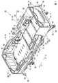
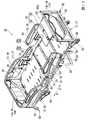
図7に示すように、背ボトム21は、寝台装置10の支持架台12に取付けられる第1本体フレーム61と、表裏面が上下方向Zに向けられた状態で、第1本体フレーム61の上面に載置された第1ボトム部材62と、第1ボトム部材62を第1本体フレーム61に離脱自在に固定する第1固定部材63と、を備えている。
また同様に、図1に示すように、腰ボトム22は、第2本体フレーム71、第2ボトム部材72、及び第2固定部材73を備えている。また、脚ボトム23のうち、膝ボトム24は、第3本体フレーム81、第3ボトム部材82、及び第3固定部材83を備え、足ボトム25は、図示しない第4本体フレーム91、第4ボトム部材92、及び第4固定部材94(図3参照)を備えている。
以下、背ボトム21について第1本体フレーム61、第1ボトム部材62、及び第1固定部材63の構造を説明する。As shown in FIG. 7, the back bottom 21 is attached to the upper surface of the first
Similarly, as shown in FIG. 1, the waist bottom 22 includes a second
Hereinafter, the structures of the first
図8に示すように、第1本体フレーム61は、上面視で矩形状を呈する枠状部材である。第1本体フレーム61は、左右方向Yに間隔をあけて配設されるとともに、前後方向Xに延びる一対の縦フレーム部61aと、一対の縦フレーム部61aの頭側Hの端部同士を連結し、左右方向Yに延びる横フレーム部61bと、一対の縦フレーム部61aにおける足側Fの端部同士を連結し、左右方向Yに延びる支持フレーム部61dと、を備えている。 As shown in FIG. 8, the first
一対の縦フレーム部61a及び横フレーム部61bは、互いに一体に形成されている。
一対の縦フレーム部61a及び横フレーム部61bは、それぞれが延びる方向に直交する断面視で、矩形状を呈する筒状に形成されている。一対の縦フレーム部61aと横フレーム部61bとの接続部分はそれぞれ、寝台装置10の外側に向けて突の曲面状に形成されている。一対の縦フレーム部61a及び横フレーム部61bの外表面のうち、上方を向く上面の幅寸法は、全域にわたって同等となっている。The pair of
The pair of
支持フレーム部61dは、左右方向Yに直交する断面視で矩形状を呈する筒状に形成されている。支持フレーム部61dのうち、左右方向Yの一方側に位置する部分には、第1駆動機構53が取り付けられる連結体55が配設されている。連結体55は、支持フレーム部61dの外表面のうち、下方を向く下面及び足側Fを向く後面に跨って一体に接続され、足側Fに向かうに従って、漸次下方に向けて延びている。 The
支持フレーム部61dの上面における幅寸法は、一対の縦フレーム部61a及び横フレーム部61bの上面における幅寸法よりも大きくなっている。支持フレーム部61dの上面における左右方向Yの中央部には、支持フレーム部61dの上面を上下方向Zに貫通するフレーム連通孔61eが形成されている。
支持フレーム部61dの左右方向Yの両端部には、第1回動軸26aに連結される回動部材56が各別に配設されている。The width dimension on the upper surface of the
Rotating
第1本体フレーム61には、支持フレーム部61dと、横フレーム部61bと、を接続し、前後方向Xに延びる補強フレーム部61g、61hが複数配設されている。補強フレーム部61g、61hは、第1本体フレーム61における左右方向Yの中央部に位置する第1補強フレーム部61gと、左右方向Yの外側に位置する一対の第2補強フレーム部61hと、を備えている。一対の第2補強フレーム部61hと、これらそれぞれの左右方向Yの外側に位置する縦フレーム部61aと、の間に、複数の連結板64が配設されている。 The first
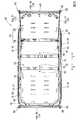
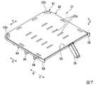
図9に示すように、第1ボトム部材62は、上面視で4つの辺部を有する矩形状を呈する板状に形成されている。第1ボトム部材62は例えば板金等により形成され、表裏面が上下方向Zを向いている。第1ボトム部材62の表裏面には、この表裏面を貫通する複数の長孔62aが形成されている。第1ボトム部材62の頭側Hの端部における左右方向Yの両端部には、左右方向Yの内側及び足側Fに向けて切り欠かれた切り欠き部62bが各別に形成されている。 As shown in FIG. 9, the
切り欠き部62bは、第1ボトム部材62の左右方向Yの両端部に位置する辺部において、頭側Hの端部から左右方向Yの内側に延びる横縁62pと、第1ボトム部材62の頭側Hに位置する辺部において、左右方向Yの両端部から足側Fに延びる縦縁62qと、横縁62pと縦縁62qとを接続する接続縁62rと、により形成されている。図7に示すように、切り欠き部62bは、第1本体フレーム61における一対の縦フレーム部61aと横フレーム部61bとの接続部分の内側と、上下方向Zで連通している。 The
図9に示すように、第1ボトム部材62の外周縁は、下方に向けて屈曲している。このため、第1ボトム部材62を第1本体フレーム61に載置する際に、第1ボトム部材62の外周縁内に、第1本体フレーム61の外側面をはめ込むことで、第1本体フレーム61に対して、第1ボトム部材62を位置決めすることができる。
第1ボトム部材62の外周縁部における4つの辺部のうち、足側Fに位置する部分における左右方向Yの中央部には、第1ボトム部材62を上下方向Zに貫通するボトム連通孔62cが形成されている。As shown in FIG. 9, the outer peripheral edge of the
Of the four side portions on the outer peripheral edge of the
そして本実施形態では、図1に示すように、第1固定部材63は、第1ボトム部材62の上面に配設されている。第1固定部材63は、図10に示すように、上下方向Zに延びる軸体63aと、軸体63aの上端部に配設された環状のフランジ部63bと、を備えている。第1固定部材63は合成樹脂材料により形成されている。軸体63a及びフランジ部63bは互いに別体とされ、フランジ部63b内に軸体63aが挿入されている。
第1固定部材63は、フランジ部63bが第1ボトム部材62の上面に配置され、軸体63aが、第1本体フレーム61のフレーム連通孔61e、及び第1ボトム部材62のボトム連通孔62cに一体に挿入されることで、第1ボトム部材62を、第1本体フレーム61に固定する。軸体63aは頭部に十字溝が形成された雄ねじ部材となっている。Then, in the present embodiment, as shown in FIG. 1, the first fixing
In the first fixing
また本実施形態では、フランジ部63bは、下方を向いて第1ボトム部材62の上面に載置される下面と、下面の外周縁から内側に向かうに従い漸次、上方に向けて延びる突曲面63cと、により構成されている。
フランジ部63bの下面の内周縁部には、下方に向けて延び、フランジ部63bの径方向に弾性変形可能な係止片63dが形成されている。係止片63dは、フランジ部63bの周方向に間隔をあけて複数形成されている。係止片63dには、径方向の内側に向けて突出し、軸体63aの雄ねじ部と係合する不図示の突起が形成されている。Further, in the present embodiment, the
A
フランジ部63bの上面における内周縁部には、下方に向けて窪み、軸体63aの頭部が収容されるザグリ穴63eが形成されている。軸体63aをフランジ部63b内に挿入することで、係止片63dが径方向の外側に向けて弾性変形し、係止片63dの外面がボトム連通孔62c及びフレーム連通孔61eの各内周面に密接する。軸体63aの頭部がフランジ部63bのザグリ穴63eに収容された状態において、フランジ部63bの上面と、軸体63aの頭部の上面と、は上下方向Zの段差なく連なっている。
また、軸体63aの頭部を軸体63aの中心軸回りに回転させることで、係止片63dの前記突起が軸体63aのねじ溝に沿って相対移動し、これにより軸体63aがフランジ部63bから上下方向Zに移動し、第1固定部材63を取り外すことができる。A
Further, by rotating the head of the
そして本実施形態では、図9に示すように、第1ボトム部材62の外周縁部における4つの辺部のうち、第1固定部材63が配設された辺部と異なる辺部には、第1本体フレーム61の下面に、第1本体フレーム61の下面に係止する第1係止部65が配設されている。第1係止部65は、第1ボトム部材62の外周縁部における4つの辺部のうち、横フレーム部61bに載置される辺部に配設されている。第1係止部65は、この辺部の左右方向Yの全長にわたって配設されている。 Then, in the present embodiment, as shown in FIG. 9, among the four side portions on the outer peripheral edge portion of the
第1ボトム部材62の外周縁部における4つの辺部のうち、第1固定部材63が配設された辺部と、第1係止部65が配設された辺部と、は、互いに対向している。図示の例では、第1固定部材63が配設された辺部と、第1係止部65が配設された辺部と、は、前後方向Xに互いに対向している。
第1ボトム部材62の外周縁部における4つの辺部のうち、第1係止部65が配設された辺部には、下方に向けて延び、下端部に第1係止部65が形成された折曲部66が配設されている。折曲部66は、この辺部の左右方向Yの全長にわたって配設されている。前述した第1ボトム部材62の4つの外周縁における屈曲部分のうちの1つが、折曲部66とされている。Of the four side portions on the outer peripheral edge portion of the
Of the four side portions on the outer peripheral edge of the
第1ボトム部材62の下面、及び第1係止部65は、上下方向Zで互いに対向し、第1ボトム部材62、折曲部66、及び第1係止部65は、互いに一体に形成されている。折曲部66、及び第1係止部65は、曲げ加工により形成される。長孔62a、及び切り欠き部62bは、金型を用いた加工やレーザ加工により形成される。 The lower surface of the
また本実施形態では、図6に示すように、背ボトム21、腰ボトム22、膝ボトム24、及び足ボトム25は、支持架台12に前後方向Xに複数並べられて配設され、背ボトム21、膝ボトム24、及び足ボトム25は、各ボトム部材62、82、92の表裏面が、前後方向Xに向かうに従い漸次、上下方向Zに延びるように水平方向に対して傾斜可能に支持されている。すなわち、背ボトム21は、頭側Hに向かうに従い漸次、上方に延びるように傾斜し、膝ボトム24は、足側Fに向かうに従い漸次、上方に延びるように傾斜する、また、足ボトム25は、頭側Hに向かうに従い漸次、上方に延びるように傾斜する。 Further, in the present embodiment, as shown in FIG. 6, a plurality of back bottom 21, waist bottom 22, knee bottom 24, and foot bottom 25 are arranged side by side in the front-rear direction X on the support pedestal 12, and the back bottom 21 is arranged. , The knee bottom 24, and the foot bottom 25 are supported so that the front and back surfaces of the
そして本実施形態では、各ボトム部材62、82、92における各係止部65、85、95は、各ボトム部材62、82、92の外周縁部における2つの左右方向に延びる辺部のうち、各ボトム部材62、82、92の表裏面が水平方向に対して傾斜した際に、上方に位置する辺部に配設されている。
すなわち、背ボトム21における第1係止部65は、第1本体フレーム61における横フレーム部61bに配設されている。また、膝ボトム24における第3係止部85は、第3本体フレーム81における足側Fの辺部に配設されている。また、足ボトム25における第4係止部95は、第4本体フレーム91(図2参照)における頭側Hの辺部に配設されている。In the present embodiment, the locking
That is, the
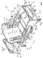
次に、寝台装置10の変形例について説明する。
図11及び図12に示すように、変形例の寝台装置20では、足側Fに位置するフットボード14bに記録台97が配設されている。記録台97は、フットボード14bに取付けられた回動軸97aによって、表裏面を足側Fに向けて回動させることで、不使用時には、フットボード14bに沿って収納することができる。Next, a modified example of the
As shown in FIGS. 11 and 12, in the
寝台装置20では、アシストバー96が配設されている。使用者が寝台11から立ち上がる際に、アシストバー96に体重をかけることで、容易に立ち上がることができる。
寝台装置20では、使用者の足元を照らす図示しないフットライトが支持架台12の下面に配設されている。
寝台装置20では、図12に示すように、膝ボトム24が、足側Fに向かうに従い漸次、上方に延びるように傾斜した際に、足ボトム25を水平方向に対して傾斜させずに昇降させることができる。In the
In the
In the
以上説明したように、本実施形態に係るボトムによれば、背ボトム21が、寝台装置10の支持架台12に取付けられる第1本体フレーム61と、第1本体フレーム61の上面に載置された第1ボトム部材62と、を備えている。このため、第1ボトム部材62の上面を例えば清拭する際等に、背ボトム21のうち、上面を有する第1ボトム部材62のみを第1本体フレーム61から取り外すことが可能になり、優れた取扱性を具備させることができる。 As described above, according to the bottom according to the present embodiment, the back bottom 21 is placed on the first
また、第1固定部材63が、第1ボトム部材62の上面に配設されているので、第1ボトム部材62の上方から第1固定部材63を操作することが可能になり、この操作時に、例えば工具を第1ボトム部材62の下方から回り込ませたり、他の部材間の隙間に進入させたりする等の必要がなく、第1ボトム部材62を第1本体フレーム61に容易に着脱することができる。
また、例えば第1本体フレーム61をパイプ等により形成し、第1ボトム部材62を板金等により形成した場合には、背ボトム21を合成樹脂材料の射出成形により一体に形成するような場合と比べて、金型製作等の初期費用を抑えることができ、背ボトム21を安価に製造することができる。Further, since the first fixing
Further, for example, when the first
また、第1ボトム部材62の外周縁部における4つの辺部のうちの少なくとも1つの辺部に第1固定部材63が配設されるとともに、他の辺部に、第1本体フレーム61の下面に、第1本体フレーム61の下面に係止する第1係止部65が配設されている。このため、第1ボトム部材62に、第1ボトム部材62を第1本体フレーム61から持ち上げるような外力が加えられた際に、第1係止部65が第1本体フレーム61の下面に係止することとなる。これにより、第1ボトム部材62に加えられたこのような外力を、第1固定部材63だけでなく、第1係止部65によっても受け止めさせることができる。その結果、第1ボトム部材62のうち、第1固定部材63の周囲に位置する部分に大きな力がかかるのを抑制することが可能になり、第1ボトム部材62に局所的な変形が生じるのを抑えることができる。 Further, the first fixing
また、第1係止部65が、第1ボトム部材62の辺部のうち、第1固定部材63が配設された辺部から最も離れた辺部に配設されることになるので、第1固定部材63と第1係止部65との間の距離を大きく確保することできる。このため、第1ボトム部材62のうち、第1固定部材63が配設された辺部から最も離れた辺部に、第1ボトム部材62を第1本体フレーム61から持ち上げるような外力が加えられた際には、第1固定部材63周りに発生する回転モーメントを第1係止部65により受けることで、第1係止部65に生じる反力を小さくすることが可能になる。これにより、確実に第1ボトム部材62を第1本体フレーム61に係止することができる。 Further, since the
また、折曲部66及び第1係止部65を、例えば第1ボトム部材62に曲げ加工を施すことにより形成することができ、第1ボトム部材62を安価に製造することができる。
また、軸体63aを、第1本体フレーム61及び第1ボトム部材62に、各別に形成されたフレーム連通孔61e、及びボトム連通孔62cに一体に挿入するとともに、フランジ部63bを第1ボトム部材62の上面に配置することで、第1ボトム部材62を第1本体フレーム61に固定することができる。これにより、第1ボトム部材62を第1本体フレーム61に着脱する際に、第1ボトム部材62の上面から上方に突出したフランジ部63bを操作することが可能になり、この着脱操作を容易に行うことができる。Further, the
Further, the
また、第1ボトム部材62の上面に載置される第1固定部材63の下面の外周縁部から、突曲面63cが接続されているので、第1固定部材63におけるフランジ部63bの外周縁と、第1ボトム部材62の上面と、の間に段差が生ずるのを抑制することが可能になり、このような段差に物などが引っ掛かるのを抑制することができる。
また、寝台装置10が背ボトム21を備えているので、寝台装置10において上記の作用効果を奏功させることができる。Further, since the protruding
Further, since the
また、第1係止部65が、第1ボトム部材62の外周縁部における2つの左右方向に延びる辺部のうち、第1ボトム部材62の表裏面を水平方向に対して傾斜させた際に、上方に位置する辺部に配設されている。このため、第1ボトム部材62の表裏面が水平方向に対して傾斜したことにより、第1本体フレーム61の上面で支えることができない第1ボトム部材62の自重を、第1固定部材63だけでなく、第1係止部65にも受け止めさせることができ、第1固定部材63にかかる負荷を抑えることができる。
なお、上記した各作用効果は、背ボトム21に限られず、他のボトムにおいても奏功することができる。Further, when the
It should be noted that each of the above-mentioned effects can be effective not only in the back bottom 21 but also in other bottoms.
なお、本発明の技術的範囲は前記実施形態に限定されるものではなく、本発明の趣旨を逸脱しない範囲において種々の変更を加えることが可能である。
例えば、上記実施形態では、第1ボトム部材62が上面視で矩形状を呈する板状に形成された構成を示したが、このような態様に限られない。第1ボトム部材は上面視で矩形状以外の形状を呈してもよい。The technical scope of the present invention is not limited to the above-described embodiment, and various modifications can be made without departing from the spirit of the present invention.
For example, in the above embodiment, the
また、上記実施形態では、第1ボトム部材62の辺部のうち、第1固定部材63が配設された辺部と異なる辺部に、第1係止部65が配設された構成を示したが、このような態様に限られない。第1ボトム部材に第1係止部が配設されていなくてもよい。
また、上記実施形態では、第1固定部材が第1ボトム部材62に1つ配設された構成を示したが、このような態様に限られない。固定部材はボトム部材に複数配設されてもよい。
また、上記実施形態では、第1固定部材63が配設された辺部と、第1係止部65が配設された辺部と、が互いに対向している構成を示したが、このような態様に限られない。
第1係止部と第1固定部材とは、互いに対向していなくてもよいし、同じ辺部に配置されてもよい。Further, in the above embodiment, among the side portions of the
Further, in the above embodiment, the configuration in which one first fixing member is arranged on the
Further, in the above embodiment, the side portion on which the first fixing
The first locking portion and the first fixing member may not face each other or may be arranged on the same side portion.
また、上記実施形態では、第1固定部材63は軸体63aとフランジ部63bとを備え、フランジ部63bが、下面と突曲面63cとにより形成された構成を示したが、このような態様に限られない。例えば、第1固定部材は単なる雄ねじ部材等であってもよいし、フランジ部が突曲面により形成されていなくてもよい。また、第1固定部材は金属材料により形成された部材であってもよい。
なお、上記した変形例は、背ボトム21に限られず、他のボトムにおいても適用することができる。Further, in the above embodiment, the first fixing
The above-mentioned modification can be applied not only to the back bottom 21 but also to other bottoms.
その他、本発明の趣旨に逸脱しない範囲で、前記実施形態における構成要素を周知の構成要素に置き換えることは適宜可能であり、また、前記した変形例を適宜組み合わせてもよい。 In addition, it is possible to replace the constituent elements in the above-described embodiment with well-known constituent elements as appropriate without departing from the spirit of the present invention, and the above-mentioned modified examples may be appropriately combined.
10 寝台装置
21 背ボトム(ボトム)
61 第1本体フレーム(本体フレーム)
61e フレーム連通孔
62 第1ボトム部材
62c ボトム連通孔
63 第1固定部材
63a 軸体
63b フランジ部10
61 1st body frame (body frame)
61e
Claims (5)
Translated fromJapanese前記本体フレームの上面に載置されたボトム部材と、
前記ボトム部材を前記本体フレームに離脱自在に固定でき、前記ボトム部材の上面に配設された固定部材と、を備え、
前記ボトム部材は、前記ボトム部材の外周縁の一部において下方に延びた折曲部と、前記折曲部の下端部に形成され、前記本体フレームの下面に係止する係止部とを含み、前記ボトム部材のうちで前記固定部材が配設された部分と前記係止部が配設された部分とは互いに、前記寝台装置の長手方向において対向していることを特徴とするボトム。The main frame of the sleeper and
The bottom member placed on the upper surface of the main body frame and
The bottom member can be detachably fixed to the main body frame, and a fixing member disposed on the upper surface of the bottom member is provided.
The bottom member includesa bent portion extending downward at a part of the outer peripheral edge of the bottom member,and a locking portion formed at the lower end portion of the bent portion and locked to the lower surface of the main body frame. A bottom of the bottom member, wherein the portion on which the fixing member is arranged and the portion on which the locking portion is arranged face each other in the longitudinal direction of the sleeper device.
前記本体フレームの上面に載置されたボトム部材と、
前記ボトム部材を前記本体フレームに離脱自在に固定でき、前記ボトム部材の上面に配設された固定部材と、を備え、
前記ボトム部材は、前記ボトム部材の外周縁の一部において下方に延びた折曲部と、前記折曲部の下端部に形成され、前記本体フレームの下面に前記固定部材よりも先に係止する係止部とを含み、前記ボトム部材のうちで前記固定部材が配設された部分と前記係止部が配設された部分とは互いに、前記寝台装置の長手方向において対向しており、
前記ボトム部材の辺部には、前記折曲部が配設され、前記ボトム部材、前記折曲部、及び前記係止部は、互いに一体に形成されていることを特徴とするボトム。The main frame of the sleeper and
The bottom member placed on the upper surface of the main body frame and
The bottom member can be detachably fixed to the main body frame, and a fixing member disposed on the upper surface of the bottom member is provided.
The bottom member is formed at a bent portion extending downward at a part of the outer peripheral edge of the bottom member and at the lower end portion of the bent portion, and is locked to the lower surface of the main body frame before the fixing member. The portion of the bottom member on which the fixing member is arranged and the portion on which the locking portion is arranged face each other in the longitudinal direction of the sleeper device.
Wherein the side portion of the bottom member,the bent portion is disposed, the bottom member, the bent portion, and the locking portion includes abottom, characterized in that it is formed integral with one another.
前記固定部材は、上下方向に延びる軸体と、前記軸体の上端部に配設されたフランジ部と、を備え、
前記固定部材は、前記フランジ部が前記ボトム部材の上面に配置され、前記軸体が前記本体フレーム及び前記ボトム部材の各連通孔に一体に挿入された状態で、前記ボトム部材を、前記本体フレームに固定していることを特徴とする請求項1または請求項2に記載のボトム。Communication holes that communicate with each other in the vertical direction are separately formed in the main body frame and the bottom member.
The fixing member includes a shaft body extending in the vertical direction and a flange portion disposed at the upper end portion of the shaft body.
In the fixing member, the bottom member is inserted into the main body frame in a state where the flange portion is arranged on the upper surface of the bottom member and the shaft body is integrally inserted into the communication holes of the main body frame and the bottom member. The bottom according to claim 1 or 2, wherein the bottom is fixed to.
前記ボトムが取付けられた支持架台と、を備える寝台装置であって、
前記ボトムは、請求項1〜4のいずれか1項に記載のボトムであることを特徴とする寝台装置。With the bottom
A sleeper device including a support pedestal to which the bottom is attached.
The sleeper device according to any one of claims 1 to 4, wherein the bottom is the bottom.
Priority Applications (1)
| Application Number | Priority Date | Filing Date | Title |
|---|---|---|---|
| JP2018043632AJP6853796B2 (en) | 2018-03-09 | 2018-03-09 | Bottom and sleeper |
Applications Claiming Priority (1)
| Application Number | Priority Date | Filing Date | Title |
|---|---|---|---|
| JP2018043632AJP6853796B2 (en) | 2018-03-09 | 2018-03-09 | Bottom and sleeper |
Related Parent Applications (1)
| Application Number | Title | Priority Date | Filing Date |
|---|---|---|---|
| JP2016190500ADivisionJP6307571B2 (en) | 2016-09-29 | 2016-09-29 | Bottom and bed apparatus |
Publications (2)
| Publication Number | Publication Date |
|---|---|
| JP2018114304A JP2018114304A (en) | 2018-07-26 |
| JP6853796B2true JP6853796B2 (en) | 2021-03-31 |
Family
ID=62984792
Family Applications (1)
| Application Number | Title | Priority Date | Filing Date |
|---|---|---|---|
| JP2018043632AActiveJP6853796B2 (en) | 2018-03-09 | 2018-03-09 | Bottom and sleeper |
Country Status (1)
| Country | Link |
|---|---|
| JP (1) | JP6853796B2 (en) |
Families Citing this family (1)
| Publication number | Priority date | Publication date | Assignee | Title |
|---|---|---|---|---|
| JP7621886B2 (en) | 2021-05-31 | 2025-01-27 | パラマウントベッド株式会社 | bed |
Family Cites Families (7)
| Publication number | Priority date | Publication date | Assignee | Title |
|---|---|---|---|---|
| JPH0640428U (en)* | 1992-10-29 | 1994-05-31 | 株式会社ニフコ | Push rivets |
| JP2003116932A (en)* | 2001-10-12 | 2003-04-22 | Norihiko Hayashi | Structure for bed |
| JP2004147897A (en)* | 2002-10-31 | 2004-05-27 | Iris Chitose Kk | Plate mounting structure of chair |
| US9038217B2 (en)* | 2005-12-19 | 2015-05-26 | Stryker Corporation | Patient support with improved control |
| JP5434211B2 (en)* | 2009-04-09 | 2014-03-05 | トヨタ紡織株式会社 | Assembly structure of sheet-like elastic body for vehicle seat |
| WO2014015320A1 (en)* | 2012-07-20 | 2014-01-23 | Ergomotion, Inc. | Articulating bed with flexible mattress support |
| JP5364198B1 (en)* | 2012-11-05 | 2013-12-11 | 第一工業株式会社 | Chair rivets and chairs |
- 2018
- 2018-03-09JPJP2018043632Apatent/JP6853796B2/enactiveActive
Also Published As
| Publication number | Publication date |
|---|---|
| JP2018114304A (en) | 2018-07-26 |
Similar Documents
| Publication | Publication Date | Title |
|---|---|---|
| JP6853796B2 (en) | Bottom and sleeper | |
| WO2005032308A1 (en) | Mattress with hand support | |
| JP6997631B2 (en) | Bottom member, bottom, and bed device | |
| JP6704305B2 (en) | Auxiliary fence and bed equipment | |
| JP6307571B2 (en) | Bottom and bed apparatus | |
| JP6618859B2 (en) | Bed equipment | |
| JP6869311B2 (en) | Sleeper | |
| JP5089785B2 (en) | Reclining bed | |
| JP5138081B1 (en) | mattress | |
| JP6768980B2 (en) | Sleeper | |
| CN112842730B (en) | Bed device | |
| JP6681684B2 (en) | Sleeper device | |
| JP4566069B2 (en) | Electric bed | |
| JP6982658B2 (en) | Sleeper components and sleeper equipment | |
| JP2019084248A (en) | Electric bed | |
| JP4371742B2 (en) | Electric bed | |
| JP6647065B2 (en) | Bed apparatus | |
| WO2017187596A1 (en) | Bed | |
| JP7165801B2 (en) | bed component and bed device | |
| JP6570378B2 (en) | Bed apparatus and fence body | |
| JP7314195B2 (en) | bed equipment | |
| JP6860638B2 (en) | Sleeper | |
| JP6639126B2 (en) | bed | |
| JP2006109882A (en) | Bed and bed board protector | |
| JP6595264B2 (en) | Bed equipment |
Legal Events
| Date | Code | Title | Description |
|---|---|---|---|
| A621 | Written request for application examination | Free format text:JAPANESE INTERMEDIATE CODE: A621 Effective date:20190308 | |
| RD01 | Notification of change of attorney | Free format text:JAPANESE INTERMEDIATE CODE: A7421 Effective date:20190424 | |
| A977 | Report on retrieval | Free format text:JAPANESE INTERMEDIATE CODE: A971007 Effective date:20200220 | |
| A131 | Notification of reasons for refusal | Free format text:JAPANESE INTERMEDIATE CODE: A131 Effective date:20200302 | |
| A521 | Request for written amendment filed | Free format text:JAPANESE INTERMEDIATE CODE: A523 Effective date:20200415 | |
| A131 | Notification of reasons for refusal | Free format text:JAPANESE INTERMEDIATE CODE: A131 Effective date:20200727 | |
| A521 | Request for written amendment filed | Free format text:JAPANESE INTERMEDIATE CODE: A523 Effective date:20200924 | |
| TRDD | Decision of grant or rejection written | ||
| A01 | Written decision to grant a patent or to grant a registration (utility model) | Free format text:JAPANESE INTERMEDIATE CODE: A01 Effective date:20210305 | |
| A61 | First payment of annual fees (during grant procedure) | Free format text:JAPANESE INTERMEDIATE CODE: A61 Effective date:20210312 | |
| R150 | Certificate of patent or registration of utility model | Ref document number:6853796 Country of ref document:JP Free format text:JAPANESE INTERMEDIATE CODE: R150 | |
| R250 | Receipt of annual fees | Free format text:JAPANESE INTERMEDIATE CODE: R250 |