JP6853765B2 - Cool box - Google Patents
Cool boxDownload PDFInfo
- Publication number
- JP6853765B2 JP6853765B2JP2017209611AJP2017209611AJP6853765B2JP 6853765 B2JP6853765 B2JP 6853765B2JP 2017209611 AJP2017209611 AJP 2017209611AJP 2017209611 AJP2017209611 AJP 2017209611AJP 6853765 B2JP6853765 B2JP 6853765B2
- Authority
- JP
- Japan
- Prior art keywords
- lid
- support
- storage box
- cold storage
- cylinder
- Prior art date
- Legal status (The legal status is an assumption and is not a legal conclusion. Google has not performed a legal analysis and makes no representation as to the accuracy of the status listed.)
- Active
Links
- XLYOFNOQVPJJNP-UHFFFAOYSA-NwaterSubstancesOXLYOFNOQVPJJNP-UHFFFAOYSA-N0.000claimsdescription27
- 210000000078clawAnatomy0.000claimsdescription17
- 239000011347resinSubstances0.000claimsdescription6
- 229920005989resinPolymers0.000claimsdescription6
- 229910052710siliconInorganic materials0.000claimsdescription2
- 239000010703siliconSubstances0.000claimsdescription2
- XUIMIQQOPSSXEZ-UHFFFAOYSA-NSiliconChemical compound[Si]XUIMIQQOPSSXEZ-UHFFFAOYSA-N0.000claims1
- 210000003811fingerAnatomy0.000description9
- 241000251468ActinopterygiiSpecies0.000description4
- 239000000463materialSubstances0.000description3
- 230000004048modificationEffects0.000description3
- 238000012986modificationMethods0.000description3
- 238000007599dischargingMethods0.000description2
- 238000000465mouldingMethods0.000description2
- 210000003813thumbAnatomy0.000description2
- 238000009413insulationMethods0.000description1
- 238000002844meltingMethods0.000description1
- 230000008018meltingEffects0.000description1
- 230000002093peripheral effectEffects0.000description1
- 238000005096rolling processMethods0.000description1
- 239000013535sea waterSubstances0.000description1
- 238000007789sealingMethods0.000description1
Images


Classifications
- B—PERFORMING OPERATIONS; TRANSPORTING
- B65—CONVEYING; PACKING; STORING; HANDLING THIN OR FILAMENTARY MATERIAL
- B65D—CONTAINERS FOR STORAGE OR TRANSPORT OF ARTICLES OR MATERIALS, e.g. BAGS, BARRELS, BOTTLES, BOXES, CANS, CARTONS, CRATES, DRUMS, JARS, TANKS, HOPPERS, FORWARDING CONTAINERS; ACCESSORIES, CLOSURES, OR FITTINGS THEREFOR; PACKAGING ELEMENTS; PACKAGES
- B65D81/00—Containers, packaging elements, or packages, for contents presenting particular transport or storage problems, or adapted to be used for non-packaging purposes after removal of contents
- B65D81/38—Containers, packaging elements, or packages, for contents presenting particular transport or storage problems, or adapted to be used for non-packaging purposes after removal of contents with thermal insulation
- B65D81/3813—Containers, packaging elements, or packages, for contents presenting particular transport or storage problems, or adapted to be used for non-packaging purposes after removal of contents with thermal insulation rigid container being in the form of a box, tray or like container
- A—HUMAN NECESSITIES
- A01—AGRICULTURE; FORESTRY; ANIMAL HUSBANDRY; HUNTING; TRAPPING; FISHING
- A01K—ANIMAL HUSBANDRY; AVICULTURE; APICULTURE; PISCICULTURE; FISHING; REARING OR BREEDING ANIMALS, NOT OTHERWISE PROVIDED FOR; NEW BREEDS OF ANIMALS
- A01K97/00—Accessories for angling
- A01K97/20—Keepnets or other containers for keeping captured fish
- B—PERFORMING OPERATIONS; TRANSPORTING
- B65—CONVEYING; PACKING; STORING; HANDLING THIN OR FILAMENTARY MATERIAL
- B65D—CONTAINERS FOR STORAGE OR TRANSPORT OF ARTICLES OR MATERIALS, e.g. BAGS, BARRELS, BOTTLES, BOXES, CANS, CARTONS, CRATES, DRUMS, JARS, TANKS, HOPPERS, FORWARDING CONTAINERS; ACCESSORIES, CLOSURES, OR FITTINGS THEREFOR; PACKAGING ELEMENTS; PACKAGES
- B65D81/00—Containers, packaging elements, or packages, for contents presenting particular transport or storage problems, or adapted to be used for non-packaging purposes after removal of contents
- B65D81/18—Containers, packaging elements, or packages, for contents presenting particular transport or storage problems, or adapted to be used for non-packaging purposes after removal of contents providing specific environment for contents, e.g. temperature above or below ambient
- B—PERFORMING OPERATIONS; TRANSPORTING
- B65—CONVEYING; PACKING; STORING; HANDLING THIN OR FILAMENTARY MATERIAL
- B65D—CONTAINERS FOR STORAGE OR TRANSPORT OF ARTICLES OR MATERIALS, e.g. BAGS, BARRELS, BOTTLES, BOXES, CANS, CARTONS, CRATES, DRUMS, JARS, TANKS, HOPPERS, FORWARDING CONTAINERS; ACCESSORIES, CLOSURES, OR FITTINGS THEREFOR; PACKAGING ELEMENTS; PACKAGES
- B65D81/00—Containers, packaging elements, or packages, for contents presenting particular transport or storage problems, or adapted to be used for non-packaging purposes after removal of contents
- B65D81/24—Adaptations for preventing deterioration or decay of contents; Applications to the container or packaging material of food preservatives, fungicides, pesticides or animal repellants
- B65D81/26—Adaptations for preventing deterioration or decay of contents; Applications to the container or packaging material of food preservatives, fungicides, pesticides or animal repellants with provision for draining away, or absorbing, or removing by ventilation, fluids, e.g. exuded by contents; Applications of corrosion inhibitors or desiccators
- B65D81/261—Adaptations for preventing deterioration or decay of contents; Applications to the container or packaging material of food preservatives, fungicides, pesticides or animal repellants with provision for draining away, or absorbing, or removing by ventilation, fluids, e.g. exuded by contents; Applications of corrosion inhibitors or desiccators for draining or collecting liquids without absorbing them
- Y—GENERAL TAGGING OF NEW TECHNOLOGICAL DEVELOPMENTS; GENERAL TAGGING OF CROSS-SECTIONAL TECHNOLOGIES SPANNING OVER SEVERAL SECTIONS OF THE IPC; TECHNICAL SUBJECTS COVERED BY FORMER USPC CROSS-REFERENCE ART COLLECTIONS [XRACs] AND DIGESTS
- Y02—TECHNOLOGIES OR APPLICATIONS FOR MITIGATION OR ADAPTATION AGAINST CLIMATE CHANGE
- Y02E—REDUCTION OF GREENHOUSE GAS [GHG] EMISSIONS, RELATED TO ENERGY GENERATION, TRANSMISSION OR DISTRIBUTION
- Y02E60/00—Enabling technologies; Technologies with a potential or indirect contribution to GHG emissions mitigation
- Y02E60/14—Thermal energy storage
Landscapes
- Engineering & Computer Science (AREA)
- Mechanical Engineering (AREA)
- Life Sciences & Earth Sciences (AREA)
- Environmental Sciences (AREA)
- Food Science & Technology (AREA)
- Animal Husbandry (AREA)
- Biodiversity & Conservation Biology (AREA)
- Closures For Containers (AREA)
- Purses, Travelling Bags, Baskets, Or Suitcases (AREA)
- Packages (AREA)
- Cold Air Circulating Systems And Constructional Details In Refrigerators (AREA)
Description
Translated fromJapanese本発明は、魚などを保冷した状態で収容可能な保冷箱に関し、詳細には、水抜き部に特徴を備えた保冷箱に関する。 The present invention relates to a cold storage box capable of storing fish or the like in a cold state, and more particularly to a cold storage box having a feature of a drainage portion.
一般的に、魚釣りには、保冷箱(クーラーボックス)が携行され、氷や魚等を収容し、釣った魚を保冷した状態で搬送できるようにしている。魚を保冷している状態において、氷が溶けたことによって水分が増加した場合等、水抜きすることが行われる。水抜きは、保冷箱本体の側壁下側に配設された水抜き部を操作することで行われる。この水抜き部としては、例えば特許文献1に開示されているように、側壁に形成された開口部を閉塞しているネジ式のキャップを開いて、開口部を露出させる構成が知られている。キャップには、開口部を通じて内部にT字型の抜け止め部(イカリ)が取り付けられており、キャップを外して内部から水(海水も含む)が流出した際、キャップが脱落しないようになっている。 Generally, a cooler box is carried for fishing, and ice, fish, etc. are stored so that the caught fish can be transported in a cold state. When the fish is kept cold and the water content increases due to the melting of ice, drainage is performed. Draining is performed by operating the draining portion arranged on the lower side of the side wall of the cool box body. As the drainage portion, for example, as disclosed in Patent Document 1, a configuration is known in which a screw-type cap that closes an opening formed in a side wall is opened to expose the opening. .. A T-shaped retaining part (anchor) is attached to the inside of the cap through the opening so that the cap will not fall off when water (including seawater) flows out from the inside after removing the cap. There is.
上記した構成では、水が流出する際、流出する水がキャップにかかってしまい、キャップが汚れてしまうという問題がある。このため、特許文献2には、水抜きする際に、開口部を開いた状態にする蓋体に流出する水がかからないように、蓋体を本体に対して回動させる構成が開示されている。 In the above configuration, when the water flows out, the outflowing water gets caught on the cap, and there is a problem that the cap becomes dirty. For this reason, Patent Document 2 discloses a configuration in which the lid is rotated with respect to the main body so that the water flowing out to the lid that keeps the opening open does not come in contact with the lid when draining water. ..
上記した特許文献2に開示されている水抜き部は、蓋体を開閉する際に、蓋体に設けられた摘み部を握って時計方向/反時計方向に回転操作する必要があり、操作性が劣るという問題がある。 When opening and closing the lid, the drainage portion disclosed in Patent Document 2 needs to be rotated clockwise / counterclockwise by grasping the knob provided on the lid, and the operability is operability. There is a problem that it is inferior.
本発明は、上記した問題に着目してなされたものであり、水抜きをする際に蓋体が汚れることはなく、簡単な操作で蓋体の開閉が可能な水抜き部を備えた保冷箱を提供することを目的とする。 The present invention has been made by paying attention to the above-mentioned problems, and a cold storage box provided with a drainage portion that does not stain the lid when draining water and allows the lid to be opened and closed with a simple operation. The purpose is to provide.
上記した目的を達成するために、本発明に係る保冷箱は、本体の側壁に設けられ、内部の水を外部に放出する水抜き部を備えており、前記水抜き部は、前記本体の内部に連通し、本体の内部に溜まった水の放出流路となる筒体と、前記筒体と一体化される支持体と、前記支持体に対して回動可能に支持され、かつ、前記筒体の開口を開閉する蓋体と、を有し、前記支持体と蓋体は、弾性係合可能な係合手段によって係合され、前記蓋体に、前記係合手段による弾性係合を解除する操作部材を設けたことを特徴とする。 In order to achieve the above object, the cold storage box according to the present invention is provided on the side wall of the main body and includes a drainage portion for discharging the water inside, and the drainage portion is inside the main body. A cylinder that serves as a discharge flow path for water accumulated inside the main body, a support that is integrated with the cylinder, and a cylinder that is rotatably supported by the support and It has a lid that opens and closes the opening of the body, and the support and the lid are engaged by an elastically engageable engaging means, and the lid is disengaged from the elastic engagement by the engaging means. It is characterized in that an operating member is provided.
上記した構成の保冷箱は、水抜き部を構成している蓋体を操作することで、本体内部の水を外部に流出させることができる。前記水抜き部は、本体の内部に連通する放出流路となる筒体と、筒体と一体化される支持体とを備えており、前記蓋体は、筒体の開口を開閉するように支持体に対して回動可能に支持されている。前記支持体と蓋体は、弾性係合可能な係合手段によって係合されており、蓋体に、係合手段による弾性係合を解除する操作部材を設けたことで、操作部材を操作して弾性係合を外すだけの簡単な操作、すなわち、弾性によって係合状態にある関係を、弾性による付勢力に抗して外すだけの簡単な操作で筒体の開口を開放することができる。そして、蓋体は、支持体に対して回動可能に支持されており、回動によって筒体の開口から退避できるため、流出時に水がかかることを防止することが可能となり、蓋体が汚れることなく、衛生的に内部の水を放出できる。 In the cold storage box having the above configuration, the water inside the main body can be discharged to the outside by operating the lid body constituting the drainage portion. The drainage portion includes a tubular body that serves as a discharge flow path that communicates with the inside of the main body, and a support that is integrated with the tubular body, and the lid body opens and closes the opening of the tubular body. It is rotatably supported with respect to the support. The support and the lid are engaged by an elastically engageable engaging means, and the operating member is operated by providing the lid with an operating member for releasing the elastic engagement by the engaging means. The opening of the tubular body can be opened by a simple operation of simply disengaging the elastic engagement, that is, a relationship in which the relationship is in an engaged state by elasticity is simply disengaged against the urging force of elasticity. The lid is rotatably supported by the support and can be retracted from the opening of the cylinder by rotation, so that it is possible to prevent water from splashing at the time of outflow and the lid becomes dirty. The water inside can be discharged hygienically without any need.
本発明によれば、水抜きをする際に蓋体が汚れることはなく、簡単な操作で蓋体の開閉が可能な保冷箱が得られる。 According to the present invention, a cold storage box can be obtained in which the lid body is not soiled when draining water and the lid body can be opened and closed with a simple operation.
以下、添付図面を参照しながら、本発明に係る保冷箱の実施形態について具体的に説明する。
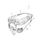
図1及び図2は、本発明に係る保冷箱の一実施形態の全体構成を示す図であり、図1は斜視図、図2は図1に示す保冷箱の水抜き部が設けられた側面を示す図である。Hereinafter, embodiments of the cool box according to the present invention will be specifically described with reference to the accompanying drawings.
1 and 2 are views showing the overall configuration of an embodiment of the cold storage box according to the present invention, FIG. 1 is a perspective view, and FIG. 2 is a side surface of the cold storage box shown in FIG. 1 provided with a drainage portion. It is a figure which shows.
保冷箱1は、断熱構造を有する断面長方形状の本体3と、本体3の縁部に対して回動自在に支持され、本体3の開口を閉塞する断熱構造を有する蓋体5と、を備えている。この場合、前記蓋体5は、本体3に対して1つの縁部に対して回動可能に支持される構造であっても良いし、1つの縁部及びこの縁部に対向する縁部の両方に対して回動可能に支持される構造(両開き構造)であっても良い。また、本体3には、保冷箱を搬送するための取手7が取り付けられている。本実施形態では、本体3の底部分にローラ6が取り付けられて転がして搬送できるキャリー搬送構造となっていることから、取手7は、本体3の短辺の縁部分に取り付けられているが、蓋体に取り付けられる構造であっても良い。 The cold insulation box 1 includes a main body 3 having a rectangular cross section having a heat insulating structure, and a
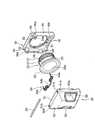
前記本体3は、略直方体形状に形成され、一対の短い側壁3Aと一対の長い側壁3Bと底壁3C(図4参照)とを備えており、短辺側の一方の側壁3Aの中央部の下方には、本体3の内部の水を外部に放出する機能を備えた水抜き部10が配設されている。以下、本実施形態の水抜き部10の構成について、図3から図9を参照して説明する。なお、これらの図において、図3は水抜き部の構成を示す斜視図、図4は保冷箱本体を内側から見た図であり、水抜き部の流出部分を示す図、図5は水抜き部を構成する蓋体の分解斜視図、図6は水抜き部の全体構成を示す分解斜視図、図7(a)は蓋体を閉じた状態を示す斜視図、図7(b)は蓋体を開いた状態を示す斜視図、図8は水抜き部の側面断面図、そして、図9は水抜き部の底面断面図である。 The main body 3 is formed in a substantially rectangular parallelepiped shape, includes a pair of
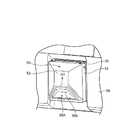
図3及び図4に示すように、水抜き部10は、側壁3Aの下側に形成された円形開口3aの部分に配設される。底壁3Cには、円形開口3aが形成される部分に、下方に窪んだ凹所3cが形成されており、円形開口3aに向けて水を案内し易いようにしている。円形開口3aに配設される水抜き部10は、円形開口3aに嵌入され、本体の内部に溜まった水の放出流路となる円筒状の筒体20と、筒体20を保持する支持体30と、支持体30に対して回動可能に支持される蓋体50とを備えている。 As shown in FIGS. 3 and 4, the
前記支持体30は、例えば樹脂製の材料で、中央に円形開口31が形成された略矩形状に構成されており、本体3の側壁3Aの外面に密着して配設される。前記筒体20は、支持体30と同様、例えば樹脂製の材料で形成されており、支持体30の円形開口31に嵌入される。筒体20には、一端側に雄ネジ部21が、他端側にフランジ22がそれぞれ形成されており、それらの間には、周方向に所定の角度をおいて回り止め用の突片23が形成されている。これらの回り止め用の突片は、略90°間隔で軸方向に沿って形成されており、9時、12時、3時方向で一つ、6時方向では2つ形成されている。 The
前記支持体30には、円形開口31の円形縁部に、前記突片23が嵌まり込む切欠き32が形成されている。このため、突片23と切欠き32を位置合わせして、筒体20を支持体30の円形開口31に嵌入することで、筒体20と支持体30は回り止め固定される。そして、両者が一体化された筒体20と支持体30は、支持体30を側壁3Aの外面に密着して配設し、この状態で、本体の内側に突出している筒体20の雄ネジ部21に、雌ネジ部25aが形成されたリング部材25を螺入することで、支持体30は本体3の側壁3Aに対して固定される。この場合、リング部材25と側壁3Aの内面との間には、Oリング26が介在されており、水漏れを防止している。また、本体3Aの開口3aの周縁部には、筒体20に形成された突片23が嵌まり込めるように、対応する位置に切欠き3eが形成されており、リング部材25を容易かつ安定して装着できるよう構成されている。 The
なお、前記筒体20と支持体30は、上記したように、それぞれ別体で形成しておき、機械的な結合或いは接着等によって一体化しても良いし、樹脂成型によって一体形成(一体化)しても良い。 As described above, the
前記支持体30の上端の両側には、一対の支持部34が突出形成されている。各支持部34には、支持孔34aが形成されており、この部分に後述する支軸53が装着される。また、支持体34の両側には、一対のサイド壁35が形成されており、各サイド壁35の下方側には、それぞれ係合部35aが形成されている。
前記係合部35aは、凹部(開口孔を含む)とすることができ、前記蓋体50との間で弾性係合可能な係合手段を構成し、蓋体50を弾性的に係合した状態(蓋体50が支持体30に対して固定された状態)で保持する機能を備える。また、各サイド壁35には、係合部35aに、後述する係止爪が案内されるように、傾斜した案内面35bが形成されている。A pair of
The engaging
前記支持体30に対しては、前記筒体20の外側の開口20Aを開閉する蓋体50が回動可能に支持されている。蓋体50の本体50Aは、例えば樹脂製の材料で一体形成することが可能であり、略矩形の枠部51と、ドーム状に膨出する膨出部52とを備えている。前記枠部51の上片の両側には、前記支持体30の一対の支持部34が入り込めるように切欠き51bが形成されている。 A
前記枠部51の両側上端には、前記支持体30に突出形成された支持部34の支持孔34aに対応するように、支持孔51aが形成されており、この部分に支軸53が配設されることで、蓋体50は、支持体30に対して上下方向に回動可能に支持されるようになっている。この支軸53は、回動スプリング54を挿通するように配設され、回動スプリング54の付勢力によって、蓋体50は、常時、支軸53を中心にして上方に開く方向(図8の矢印方向)に付勢されている。すなわち、回動スプリング54は、バネ部の両端に形成された当て付け部54aと、バネ部の中央に形成された当て付け部54bとを備えており、両端の当て付け部54aが支持体30に当て付けられ、中央の当て付け部54bが後述するプレートに当て付けられることで、蓋体50を常時、支軸53を中心にして上方に開く方向に付勢している。
前記膨出部52には、左右に略台形状の一対の開口52aが形成されている。この開口52aには、それぞれ例えば樹脂成型によって形成された操作部材(操作レバー)55が配設される。各操作部材55は、指を挿入できるように凹状に形成されており、両方の操作部材を指で挟み付ける(人差し指と親指で挟む)ことができるように垂直壁55aを備えている。また、操作部材55の互いに対向する側部には、それぞれ円形開口55bが形成されており、この部分に押圧バネ57を配設して、互いの操作部材55を離反する方向に付勢している。そして、膨出部52の裏面の上下には、各一対のガイド部52bが一体形成されており、この部分に操作部材55の板状部55dが位置付されて、操作部材55を左右方向のみに移動できるように保持している。 A pair of substantially
すなわち、両操作部材55の円形開口55bに、1つの押圧バネ57が介在されることで、両操作部材55は、指で摘まんで、付勢力に抗して互いに接近する方向に移動させることができると共に、指で摘ままないときは、押圧バネ57の付勢力によって互いに離反する方向に付勢された状態で保持される。このように、一対の操作部材55を1つの押圧バネで互いに離反する方向に付勢して係合状態にすることで、仮に一方の操作部材が誤操作で解除方向に押し込まれたとしても、他方の操作部材は押圧バネの付勢力方向に押し込まれる状態となって係合状態が解除されることはないため、確実に、誤操作による蓋体の開放を防止することができる。また、両部材間に1つの押圧バネを介在させることで構造が簡略化されて組み込み作業が容易になる。
もちろん、各操作部材に押圧バネを配設して、互いに離反する方向に付勢しても良い。That is, by interposing one pressing
Of course, a pressing spring may be provided on each operating member to urge each operating member in a direction away from each other.
前記各操作部材55には、前記支持体30のサイド壁35に形成された係合部35aに係合可能な突起付き爪55eが形成されている。この突起付き爪55eは、各操作部材55が押圧バネ57の付勢力で互いに離反する方向に付勢された状態で、傾斜した案内面35bに付勢力に抗して案内されて係合部35aに係合可能となっている。すなわち、操作部材55の突起付き爪55eと、これを受ける支持体30の係合部(凹部)35aは係合手段を構成しており、両突起付き爪55eは、押圧バネ57によって係合部35aと係合する方向に付勢されている。 Each of the operating
このため、蓋体50を回動スプリング54の付勢力に抗して支持体30に対して閉じると、突起付き爪55eが押圧バネ57による付勢力(弾性力)によって係合部35aに係合する。また、両操作部材55を押圧バネ57の付勢力に抗して操作(摘まみ操作)することで、両者の弾性係合を容易に解除することができ、蓋体50は、そのまま回動スプリング54の付勢力によって支持体30に対して回動駆動される。
なお、上記した支持体30と操作部材55に設けられる係合手段については、いずれが爪(突起)であっても良く、係合関係については、爪と凹部の係合関係であっても良いし、凸部同士で互いに係止可能な関係であっても良い。例えば、図10に示すように、支持体30のサイド壁35に凸部35fを形成しておき、この部分に、上記した突起付き爪55eを係合させるような構成であっても良い。Therefore, when the
It should be noted that any of the engaging means provided on the
前記操作部材55が組み込まれる蓋体50には、複数のビス穴60が形成されている。これらのビス穴60は、膨出部52の裏面側から、側壁3Aに対して直交する方向に突出形成されており、本実施形態では、蓋体50の四隅に4箇所形成されている。この蓋体50には、前記ビス穴60にビス(図示せず)を螺入することで板状のプレート65が取着されるようになっており、プレート65を取着することで枠部51の内側が閉塞され、前記一対の操作部材55が抜け止め保持される。
この場合、プレート65には、左右にそれぞれコの字状の切欠き65aが形成されており、プレート65によって閉塞される前記両操作部材55の突起付き爪55eが露出するようになっている。また、プレート65を蓋体50に取着すると、前記回動スプリング54は露出した状態となり、中央の当て付け部54bがプレート65上端縁65bに当て付く。A plurality of screw holes 60 are formed in the
In this case,
前記プレート65を取着した際の露出面には、筒体20の開口20Aに嵌るように円形突部65cが一体形成されている、この円形突部65cには、ゴム又はシリコン製のカバー体66を設けておくことが好ましく、これにより、蓋体20を閉じたときに、筒体20の開口20Aとの間でシール性が確保され、カバー体66が開口20Aと密着して水漏れを確実に防止することが可能となる。A
次に、上記したように本体3の側壁3Aに装着された水抜き部10の作用について説明する。
保冷箱の通常の状態では、蓋体50は、回動スプリング54の付勢力に抗して支持体30に対して係合している(図7(a)及び図8,図9参照)。このとき、蓋体50の本体50Aに取着されたプレート65のカバー体66が、筒体20の開口20Aに密着嵌合しており、内部の水が外部に漏れることはない(蓋体の閉塞状態)。また、この状態では、蓋体50の操作部材55に形成された一対の突起付き爪55eが、支持体30の係合部(凹部)35aと弾性的に係合しているため、蓋体50の回動が阻止され、水抜き部を開放することはない。Next, the operation of the
In the normal state of the cool box, the
水抜きをする場合は、一対の操作部材55の垂直壁55aを指で挟み付ける(人差し指と親指で挟む)。このとき、各操作部材55は、押圧バネ57の付勢力に抗して互いに接近する方向に移動し、各操作部材55の突起付き爪55eは、支持体30の係合部(凹部)35aから外れる。これにより、蓋体50と支持体30の係合関係が解除され、蓋体50は、回動スプリング54の付勢力によって、図8の矢印方向に回動され、図7(b)で示すように、蓋体50は開放する(筒体20の開口20Aが解放される)。この状態で、本体3内の水を、筒体20を介して外部に流出させることが可能となる。 When draining water, the
なお、本実施形態では、蓋体50の枠部51の両縁51cが、支持体30に形成されたサイド壁35の上端段部35dに当て付くことで、蓋体50の回動が規制されるようになっており、蓋体50は、支持体30(側壁3A)に対して、略90°の位置で回動が規制されるようになっている。 In the present embodiment, the rotation of the
上記のように、水抜き時では、蓋体50は、指で持ち上げ操作することなく回動スプリング54の付勢力だけで上下方向に回動して略水平位置で固定されるため、本体3を傾けて水抜きする場合、自動的に蓋体50が流出経路から退避することとなり、流出する水が蓋体50に触れることが防止され、衛生的に内部の水を放出することができる。また、支持体30と蓋体50は、弾性係合可能な係合手段によって係合しており、蓋体50に、係合手段による弾性係合を解除する操作部材55を設けたことで、操作部材55を操作(本実施形態では、一対の操作部材55を摘まむだけの簡単な操作)して弾性係合を外すだけで筒体20の開口20Aを開放することができる。 As described above, when draining water, the
また、上記した構成では、支持体30と蓋体50が、支持体に形成された支持部34に支持される支軸53を基準に位置決めできるので、係合手段である突起付き爪55eと係合部(凹部)35aを精度良く係合させることが可能となる。すなわち、係合手段の一方を、水抜き部を取り付ける本体3側に設けた構成と比べると、取り付け精度が良くなるため、両者の係合精度が良くなり、蓋体50の安定した開閉状態を確保することができる。さらに、蓋体50を閉塞するときは、回動スプリング54の付勢力に抗して蓋体50を支持体30に向けて回動し、支持体30に対して押し込むだけの簡単な操作で係合手段を係合状態に保持することができ、閉塞操作も容易に行えるようになる。 Further, in the above configuration, since the
以上、本発明の実施形態について説明したが、本発明は上記した実施形態に限定されることはなく、種々変形することが可能である。 Although the embodiments of the present invention have been described above, the present invention is not limited to the above-described embodiments and can be variously modified.
上記した実施形態では、操作部材55は、一対のレバー形態で互いに摘まむように構成していたが、上記したような係合手段で支持体30に対して係合される単一のレバーで構成しても良い。例えば、図11及び図12に示すように、操作部材55を蓋体50の膨出部52の一方側のみに配設しても良い。このような構成では、蓋体の本体50Aの裏面に、押圧バネ57の基端側を収容すると共に基端部を当て付け保持する保持部90を備えた保持壁91が設けられており、単一の操作部材55を図12の矢印D方向に付勢して、係合手段(突起付き爪55eと凹部35a)をその付勢力によって係合させている。このような構成では、蓋体を開く操作及び構造も簡略化することが可能となる。なお、蓋体50には、上記したような保持壁を設けることなく、押圧バネ57をそのまま枠部51に当て付けたり、部分的に当て付け部を形成しておき、ここに当接させても良い。 In the above-described embodiment, the operating
また、図13及び図14に示すように、操作部材55Aを上下方向に移動可能とし、下方に向けて係合手段(図示せず)が係合状態となるように押圧付勢する構成であっても良い。このような構成では、操作部材55Aの操作壁55bに指を当て、付勢力に抗して矢印D1方向に操作部材55Aを持ち上げ操作(引き上げ操作)することで係合手段の係合を解除するように構成される。このように、操作部材の操作方向についても適宜変形することが可能であり、これ以外にも、ボタン式の操作部材を押し込み操作したり、凸部材をスライド操作することで、係合手段の係合状態を解除するような構成であっても良い。さらに、蓋体の形状については、円形状にするなど、特に限定されることはない。 Further, as shown in FIGS. 13 and 14, the
1 保冷箱
3 本体
3A,3B 側壁
10 水抜き部
20 筒体
30 支持体
50 蓋体
55 操作部材1 Cool box 3
Claims (8)
Translated fromJapanese前記水抜き部は、
前記本体の内部に連通し、本体の内部に溜まった水の放出流路となる筒体と、
前記筒体と一体化され、前記側壁に形成された円形開口に前記筒体を嵌入させる支持体と、
前記支持体に対して回動可能に支持され、かつ、前記筒体の開口を開閉する蓋体と、
を有し、
前記支持体と蓋体は、弾性係合可能な係合手段によって係合され、
前記蓋体に、前記係合手段による弾性係合を解除する操作部材を設けており、
前記蓋体は、前記支持体に対し、バネによって開方向に付勢されており、前記操作部材の操作で前記係合手段の弾性係合を解除して前記蓋体を開位置に回動駆動することを特徴とする保冷箱。In a cool box provided on the side wall of the main body and provided with a drainage part that discharges the water inside.
The drainage part is
A cylinder that communicates with the inside of the main body and serves as a discharge flow path for water accumulated inside the main body.
A support that is integrated with thecylinder and that fits the cylinder into the circular opening formed in the side wall.
A lid that is rotatably supported by the support and that opens and closes the opening of the cylinder.
Have,
The support and the lid are engaged by elastically engageable engaging means.
The lid body is provided with an operating member for releasing elastic engagement by the engaging means.
The lid is urged to the support in the opening direction by a spring, and the elastic engagement of the engaging means is released by the operation of the operating member to rotate the lid to the open position. A cold storage box characterized by doing.
ことを特徴とする請求項1に記載の保冷箱。The engaging means includes a claw with a protrusion and a concave or convex portion that receives the claw.
The cold storage box according to claim 1.
ことを特徴とする請求項2に記載の保冷箱。The protruding claw is urged in a direction in which it engages with the concave or convex portion.
The cold storage box according to claim 2.
ことを特徴とする請求項1から3のいずれか1項に記載の保冷箱。The operating member comprises at least one lever that is operated against the elastic force of the engaging means.
The cold storage box according to any one of claims 1 to 3, characterized in that.
前記付勢力に抗して一対のレバーを摘まんで互いに接近する方向に操作することで、前記弾性係合が解除される、
ことを特徴とする請求項4に記載の保冷箱。The operating member includes a pair of levers that are urged by a spring member in a direction away from each other.
By pinching the pair of levers against the urging force and operating them in the direction of approaching each other, the elastic engagement is released.
The cool box according to claim 4.
ことを特徴とする請求項5に記載の保冷箱。The spring member is disposed between the pair of levers and urges both levers in a direction away from each other.
The cold storage box according to claim 5.
ことを特徴とする請求項1から6のいずれか1項に記載の保冷箱。The cold storage box according to any one of claims 1 to 6, characterized in that.
ことを特徴とする請求項1から7のいずれか1項に記載の保冷箱。The cold storage box according to any one of claims 1 to 7, characterized in that.
Priority Applications (4)
| Application Number | Priority Date | Filing Date | Title |
|---|---|---|---|
| JP2017209611AJP6853765B2 (en) | 2017-10-30 | 2017-10-30 | Cool box |
| TW107137357ATWI665140B (en) | 2017-10-30 | 2018-10-23 | Cool box |
| CN201811243850.9ACN109717162B (en) | 2017-10-30 | 2018-10-24 | Cold insulation box |
| KR1020180129735AKR102623731B1 (en) | 2017-10-30 | 2018-10-29 | Cooling box |
Applications Claiming Priority (1)
| Application Number | Priority Date | Filing Date | Title |
|---|---|---|---|
| JP2017209611AJP6853765B2 (en) | 2017-10-30 | 2017-10-30 | Cool box |
Publications (2)
| Publication Number | Publication Date |
|---|---|
| JP2019080521A JP2019080521A (en) | 2019-05-30 |
| JP6853765B2true JP6853765B2 (en) | 2021-03-31 |
Family
ID=66295419
Family Applications (1)
| Application Number | Title | Priority Date | Filing Date |
|---|---|---|---|
| JP2017209611AActiveJP6853765B2 (en) | 2017-10-30 | 2017-10-30 | Cool box |
Country Status (4)
| Country | Link |
|---|---|
| JP (1) | JP6853765B2 (en) |
| KR (1) | KR102623731B1 (en) |
| CN (1) | CN109717162B (en) |
| TW (1) | TWI665140B (en) |
Families Citing this family (4)
| Publication number | Priority date | Publication date | Assignee | Title |
|---|---|---|---|---|
| US10766672B2 (en) | 2018-12-12 | 2020-09-08 | Yeti Coolers, Llc | Insulating container |
| US11970313B2 (en) | 2018-12-12 | 2024-04-30 | Yeti Coolers, Llc | Insulating container |
| JP7311391B2 (en)* | 2019-10-25 | 2023-07-19 | 株式会社シマノ | cooler box |
| USD1040617S1 (en) | 2022-05-12 | 2024-09-03 | Yeti Coolers, Llc | Insulating container |
Family Cites Families (14)
| Publication number | Priority date | Publication date | Assignee | Title |
|---|---|---|---|---|
| US3831310A (en)* | 1973-03-08 | 1974-08-27 | G Frangullie | Live bait bucket |
| JPS62181161U (en)* | 1986-05-08 | 1987-11-17 | ||
| US4815411A (en)* | 1987-10-23 | 1989-03-28 | Burgess Dennis F | Container for carrying live fish |
| JPH01262534A (en)* | 1988-04-13 | 1989-10-19 | Konica Corp | Silver halide photographic sensitive material |
| JPH1017034A (en)* | 1996-07-05 | 1998-01-20 | Mamiya Op Co Ltd | Cold insulating box |
| JP3669666B2 (en)* | 1998-01-27 | 2005-07-13 | 株式会社シマノ | Cooler box |
| JP3993701B2 (en)* | 1998-06-19 | 2007-10-17 | 株式会社シマノ | Cooler box |
| JP4120080B2 (en)* | 1998-12-28 | 2008-07-16 | ソニー株式会社 | Imaging device and lens cap holder |
| JP4305624B2 (en)* | 2003-02-06 | 2009-07-29 | 株式会社ニフコ | Cold box latch device |
| JP2010168100A (en)* | 2009-01-26 | 2010-08-05 | Globeride Inc | Cold storage box |
| US20140252010A1 (en)* | 2013-03-11 | 2014-09-11 | Garrett Miller | Insulated Container and Drain Plug with Valve Aspect |
| JP5646009B1 (en)* | 2013-07-05 | 2014-12-24 | サーモス株式会社 | Beverage container closure |
| JP6462538B2 (en)* | 2015-08-31 | 2019-01-30 | グローブライド株式会社 | Container with open / close lid |
| CN206101379U (en)* | 2016-09-30 | 2017-04-19 | 池建勇 | Fishing box |
- 2017
- 2017-10-30JPJP2017209611Apatent/JP6853765B2/enactiveActive
- 2018
- 2018-10-23TWTW107137357Apatent/TWI665140B/enactive
- 2018-10-24CNCN201811243850.9Apatent/CN109717162B/enactiveActive
- 2018-10-29KRKR1020180129735Apatent/KR102623731B1/enactiveActive
Also Published As
| Publication number | Publication date |
|---|---|
| TWI665140B (en) | 2019-07-11 |
| KR20190049522A (en) | 2019-05-09 |
| KR102623731B1 (en) | 2024-01-12 |
| CN109717162B (en) | 2021-06-08 |
| TW201917074A (en) | 2019-05-01 |
| CN109717162A (en) | 2019-05-07 |
| JP2019080521A (en) | 2019-05-30 |
Similar Documents
| Publication | Publication Date | Title |
|---|---|---|
| JP6853765B2 (en) | Cool box | |
| EP3083430B1 (en) | Sealing mechanism for beverage container | |
| US10618730B2 (en) | Retainer mechanism | |
| EP3427615B1 (en) | Quick cup lid | |
| US10687643B2 (en) | Container with foldable elastic spout | |
| US20170327282A1 (en) | Drinking vessel lid assembly | |
| KR200353218Y1 (en) | Push-type lid of pressure cooker | |
| CN113636203A (en) | Lid with locking mechanism and container assembly including the same | |
| JP6975647B2 (en) | Cool box | |
| JP2016020241A (en) | Beverage container | |
| KR101373638B1 (en) | Cup cap of one touch type | |
| JP6466387B2 (en) | Cap unit and beverage container | |
| JP6133196B2 (en) | Beverage container | |
| JP6343704B2 (en) | Beverage container | |
| JP6754189B2 (en) | Beverage container lid lock structure | |
| JP5197314B2 (en) | Portable beverage container | |
| JP5157627B2 (en) | Portable vacuum double bottle | |
| KR20150103668A (en) | Travel mug lid | |
| KR200434633Y1 (en) | Multi-stage stackable container with middle cover | |
| JP3669666B2 (en) | Cooler box | |
| CN111207543B (en) | Ice making device and refrigerator having the same | |
| KR100539585B1 (en) | Push-type lid of pressure cooker | |
| KR100801349B1 (en) | Ice Tray Assembly For Refrigerator | |
| KR200318857Y1 (en) | Stacking type container | |
| KR200463129Y1 (en) | Container cover and container having the same |
Legal Events
| Date | Code | Title | Description |
|---|---|---|---|
| A621 | Written request for application examination | Free format text:JAPANESE INTERMEDIATE CODE: A621 Effective date:20191225 | |
| A131 | Notification of reasons for refusal | Free format text:JAPANESE INTERMEDIATE CODE: A131 Effective date:20201112 | |
| A977 | Report on retrieval | Free format text:JAPANESE INTERMEDIATE CODE: A971007 Effective date:20201111 | |
| A521 | Request for written amendment filed | Free format text:JAPANESE INTERMEDIATE CODE: A523 Effective date:20201224 | |
| TRDD | Decision of grant or rejection written | ||
| A01 | Written decision to grant a patent or to grant a registration (utility model) | Free format text:JAPANESE INTERMEDIATE CODE: A01 Effective date:20210218 | |
| A61 | First payment of annual fees (during grant procedure) | Free format text:JAPANESE INTERMEDIATE CODE: A61 Effective date:20210312 | |
| R150 | Certificate of patent or registration of utility model | Ref document number:6853765 Country of ref document:JP Free format text:JAPANESE INTERMEDIATE CODE: R150 | |
| R250 | Receipt of annual fees | Free format text:JAPANESE INTERMEDIATE CODE: R250 | |
| R250 | Receipt of annual fees | Free format text:JAPANESE INTERMEDIATE CODE: R250 |