JP6853563B2 - Equipment for transmitting information and management system - Google Patents
Equipment for transmitting information and management systemDownload PDFInfo
- Publication number
- JP6853563B2 JP6853563B2JP2016166245AJP2016166245AJP6853563B2JP 6853563 B2JP6853563 B2JP 6853563B2JP 2016166245 AJP2016166245 AJP 2016166245AJP 2016166245 AJP2016166245 AJP 2016166245AJP 6853563 B2JP6853563 B2JP 6853563B2
- Authority
- JP
- Japan
- Prior art keywords
- information
- unit
- sensor
- input
- input unit
- Prior art date
- Legal status (The legal status is an assumption and is not a legal conclusion. Google has not performed a legal analysis and makes no representation as to the accuracy of the status listed.)
- Active
Links
Images


Landscapes
- Traffic Control Systems (AREA)
- Navigation (AREA)
- Time Recorders, Dirve Recorders, Access Control (AREA)
Description
Translated fromJapanese本発明は、情報を送信する装置、及び管理システムに関する。 The present invention relates to a device for transmitting information and a management system.
バスやトラック等においては、運行記録計を搭載することが、法によって義務付けられている。運行記録計は、速度パルスや回転パルスに基づいて、車速や回転数などの運行データを記録する。運行データの記録は、車両内において、チャート紙に記録されたり、メモリカードなどの記録媒体に保存されることによって行われる。或いは、運行データは、車両外の管理サーバへ送信され、管理サーバにおいて保存される。 Buses, trucks, etc. are required by law to be equipped with an operation recorder. The operation recorder records operation data such as vehicle speed and rotation speed based on speed pulses and rotation pulses. The operation data is recorded in the vehicle by being recorded on a chart paper or stored in a recording medium such as a memory card. Alternatively, the operation data is transmitted to the management server outside the vehicle and stored in the management server.
運行データが管理サーバへ送信されるタイプのものは、運行管理システムとして構築されている(例えば、特許文献1参照)。運行管理システムにおいては、複数の車両から送信された複数の運行データを、管理サーバにおいて集中管理している。 A type in which operation data is transmitted to a management server is constructed as an operation management system (see, for example, Patent Document 1). In the operation management system, a management server centrally manages a plurality of operation data transmitted from a plurality of vehicles.
ところで、車両事故において、ドライブレコーダが事故原因の解明に役立っている。しかしながら、ドライブレコーダでは事故原因の解明が困難な場合がある。例えば、事故の状況から、「急加速した」ことが事故の直接の原因だと考えられる場合、ドライブレコーダの映像では、アクセルペダルが踏まれていないのに急加速したのか、運転手がアクセルペダルを踏んで急加速したのか判断できない。そうすると、真の事故原因が解明されないまま「運転手の操作ミス」が事故原因とされてしまう事態が生じ、事故の再発防止が達成されない。 By the way, in a vehicle accident, a drive recorder is useful for clarifying the cause of the accident. However, it may be difficult to clarify the cause of the accident with a drive recorder. For example, if the situation of the accident suggests that "rapid acceleration" is the direct cause of the accident, the driver may have suddenly accelerated even though the accelerator pedal was not depressed in the video of the drive recorder. I can't judge whether it accelerated suddenly by stepping on. Then, a situation occurs in which a "driver's operation error" is regarded as the cause of the accident without clarifying the true cause of the accident, and prevention of recurrence of the accident cannot be achieved.
また、近い将来に車両の自動運転が実用化されたとき、当該車両において事故が生じた場合において、自動運転装置側の不具合による事故であるのか、エンジンなど車両側の不具合による事故であるのかが容易に判別できれば、自動運転の安全性の向上、ひいては新たな交通システムの開発に寄与できる。 In addition, when automatic driving of a vehicle is put into practical use in the near future, if an accident occurs in the vehicle, whether it is an accident due to a malfunction on the automatic driving device side or a malfunction on the vehicle side such as the engine. If it can be easily identified, it can contribute to the improvement of the safety of autonomous driving and the development of a new transportation system.
本発明は、上記の事情に鑑みてなされたものであり、事故原因の解明に有用な情報を送信する装置、及びこの情報を送信する装置を用いた管理システムを提供することにある。 The present invention has been made in view of the above circumstances, and an object of the present invention is to provide a device for transmitting information useful for elucidating the cause of an accident and a management system using the device for transmitting this information.
(1) 本発明に係る情報を送信する装置は、車速情報が入力される車速情報入力部と、位置情報が入力される位置情報入力部と、自動運転装置が車両を操作するために出力する信号を駆動信号として、当該駆動信号が入力される駆動信号入力部と、上記駆動信号によって動作した操作部の実際の操作量を検出するセンサから操作情報が入力される操作情報入力部と、識別記号が記憶される記憶部と、情報を外部へ出力する出力部と、上記車速情報、上記位置情報、上記操作情報、及び上記識別記号を上記出力部から出力させる制御部と、を備える。上記制御部は、上記駆動信号に基いて生成され、かつ当該駆動信号が上記操作部をどのように動作させるかを判別可能な自動運転情報を上記操作情報とともに上記出力部から出力させる。(1) Thedevice for transmitting the information according to the present invention outputs a vehicle speed information input unit for inputting vehicle speed information, a position information input unit for inputting position information, and anautomatic driving device for operating the vehicle. Using the signal as a drive signal, the drive signal input unit to which the drive signal is input and the operation information input unit to which the operation information is input from the sensor that detects the actual operation amount of the operation unit operated by the drive signal are identified. It includes a storage unit for storing symbols, an output unit for outputting information to the outside, and a control unit for outputting the vehicle speed information, the position information, the operation information, and the identification symbol from the output unit.The control unit outputs automatic operation information generated based on the drive signal and capable of determining how the drive signal operates the operation unit from the output unit together with the operation information.
車速情報、位置情報、操作情報、及び識別記号は、車両の運行管理に用いられる。また、事故が生じた場合、車速情報、位置情報、操作情報、及び識別記号は、事故原因の解明、及び事故原因の証明に用いられる。 Vehicle speed information, position information, operation information, and identification symbols are used for vehicle operation management. In the event of an accident, vehicle speed information, position information, operation information, and identification symbols are used to elucidate the cause of the accident and prove the cause of the accident.
自動運転情報が操作情報とともに出力されるから、事故発生時における自動運転情報と操作情報とを対比させることができ、事故原因が自動運転装置にあるのか、車両にあるのかを判断することができる。また、判断内容を証明することができる。 Since the automatic driving information is output together with the operation information, it is possible to compare the automatic driving information and the operation information at the time of the accident, and it is possible to determine whether the cause of the accident is in the automatic driving device or the vehicle. .. In addition, the content of the judgment can be proved.
(2) 上記操作情報入力部は、ステアリングに加えられた力を検出する第1センサから上記操作情報が入力する第1入力部と、上記ステアリングの回転角度を検出する第2センサから上記操作情報が入力する第2入力部と、ブレーキペダルの操作量を検出する第3センサから上記操作情報が入力する第3入力部と、アクセルペダルの操作量を検出する第4センサから上記操作情報が入力する第4入力部と、サイドブレーキの操作を検出する第5センサから上記操作情報が入力する第5入力部と、変速ギアの位置を検出する第6センサから上記操作情報が入力する第6入力部と、ライトの点灯、消灯を検出する第7センサから上記操作情報が入力する第7入力部と、ウインカの点灯、消灯を検出する第8センサから上記操作情報が入力する第8入力部と、ドアロックの開閉を検出する第9センサから上記操作情報が入力する第9入力部と、ワイパの動作を検出する第10センサから上記操作情報が入力する第10入力部と、のうち、少なくとも1つを有していてもよい。 (2) The operation information input unit receives the operation information from the first input unit for inputting the operation information from the first sensor for detecting the force applied to the steering and the operation information from the second sensor for detecting the rotation angle of the steering. The operation information is input from the second input unit, the third input unit that detects the operation amount of the brake pedal, the third input unit that detects the operation amount of the accelerator pedal, and the fourth sensor that detects the operation amount of the accelerator pedal. The fourth input unit for detecting the operation of the side brake, the fifth input unit for inputting the operation information from the fifth sensor for detecting the operation of the side brake, and the sixth input for inputting the operation information from the sixth sensor for detecting the position of the transmission gear. The unit, the 7th input unit in which the operation information is input from the 7th sensor that detects the on / off of the light, and the 8th input unit in which the operation information is input from the 8th sensor that detects the on / off of the blinker. , At least of the 9th input unit in which the operation information is input from the 9th sensor that detects the opening / closing of the door lock and the 10th input unit in which the operation information is input from the 10th sensor that detects the operation of the wiper. You may have one.
第1入力部により、事故前後において運転手がステアリングにどのような力を加えたかがわかる。第2入力部により、事故前後において運転手がステアリングをどのように回転させたかがわかる。第3入力部により、事故前後において運転手がブレーキペダルをどのように踏み込んだかがわかる。第4入力部により、事故前後において運転手がアクセルペダルをどのように踏み込んだかがわかる。第5入力部により、事故前後において運転手がサイドブレーキを操作したかがわかる。第6入力部により、事故発生時のギア位置がわかる。第7入力部により、事故発生時のライトの点灯状況がわかる。第8入力部により、事故発生時のウインカの点灯状況がわかる。第9入力部により、事故発生時のドアロックの開閉状況がわかる。第10入力部により、事故発生時のワイパの使用状況がわかる。 From the first input unit, it is possible to know what kind of force the driver applied to the steering before and after the accident. The second input unit shows how the driver rotated the steering wheel before and after the accident. The third input unit shows how the driver depressed the brake pedal before and after the accident. The fourth input unit shows how the driver depressed the accelerator pedal before and after the accident. The fifth input unit indicates whether the driver operated the side brake before and after the accident. From the sixth input unit, the gear position at the time of the accident can be known. From the 7th input unit, the lighting status of the light at the time of the accident can be known. From the eighth input unit, the lighting status of the winker at the time of the accident can be known. From the ninth input unit, the opening / closing status of the door lock at the time of an accident can be known. From the tenth input unit, the usage status of the wiper at the time of the accident can be known.
(3) 本発明に係る情報を送信する装置は、環境センサをさらに備えていてもよい。上記環境センサは、気圧を検出する第1検出部と、温度を検出する第2検出部と、湿度を検出する第3検出部と、車内の空気成分を検出する第4検出部とのうち、少なくとも1つの検出部を有する。上記制御部は、上記環境センサが出力したした環境情報を上記操作情報とともに上記出力部から出力させる。(3) The device for transmitting information according to the present invention may further include an environmental sensor. The environmental sensor includes a first detection unit that detects atmospheric pressure, a second detection unit that detects temperature, a third detection unit that detects humidity, and a fourth detection unit that detects air components in a vehicle. It has at least one detector. The control unit outputs the environmental information output by the environmental sensor together with the operation information from the output unit.
気圧、温度、湿度、及び車内の空気成分の環境情報は、事故原因の解明に役立てられる。 Environmental information on atmospheric pressure, temperature, humidity, and air components in the car is useful for clarifying the cause of the accident.
(4) 本発明に係る情報を送信する装置は、車両に搭載された油圧システムの油圧を示す油圧情報が入力される第11入力部と、車両の冷却水の水温を示す水温情報が入力される第12入力部と、車両の燃料残量を示す燃料情報が入力される第13入力部と、のうち少なくとも1つを有する状態情報入力部をさらに備えていてもよい。上記制御部は、上記状態情報入力部から入力された上記状態情報を上記出力部から出力させる。(4) In the device for transmitting information according to the present invention, the eleventh input unit for inputting the hydraulic information indicating the hydraulic pressure of the hydraulic system mounted on the vehicle and the water temperature information indicating the water temperature of the cooling water of the vehicle are input. A state information input unit having at least one of a twelfth input unit and a thirteenth input unit for inputting fuel information indicating the remaining fuel amount of the vehicle may be further provided. The control unit outputs the state information input from the state information input unit from the output unit.
事故が発生したときの油圧や冷却水温度や燃料の残量などの情報がさらに得られる。 Further information such as oil pressure, cooling water temperature, and remaining fuel level when an accident occurs can be obtained.
(5) 本発明に係る情報を送信する装置は、加速度センサから加速度情報が入力される加速度情報入力部をさらに備えていてもよい。上記制御部は、上記加速度情報及び上記操作情報から急ハンドルと急加速と急ブレーキと障害物とのうち少なくとも1つを判断する判断処理を行い、当該判断処理において急ハンドル、急加速、急ブレーキ、或いは障害物と判断したことを条件に、注意情報を上記出力部から出力させる。(5) The device for transmitting information according to the present invention may further include an acceleration information input unit in which acceleration information is input from an acceleration sensor. The control unit performs a judgment process for determining at least one of a sudden steering wheel, a sudden acceleration, a sudden braking, and an obstacle from the acceleration information and the operation information, and in the judgment process, the sudden steering wheel, the sudden acceleration, and the sudden braking Or, on condition that it is determined to be an obstacle, caution information is output from the above output unit.
運転手が急ハンドルや急加速や急ブレーキを行ったことや、道路に障害物があることなどをリアルタイムで確認することができる。 It is possible to confirm in real time that the driver has made a sudden steering wheel, sudden acceleration or sudden braking, and that there is an obstacle on the road.
(6) 本発明に係る情報を送信する装置は、時刻情報を出力するクロックモジュールをさらに備えていてもよい。上記制御部は、上記時刻情報を上記操作情報とともに上記出力部から出力させる。(6) The device for transmitting information according to the present invention may further include a clock module that outputs time information. The control unit outputs the time information together with the operation information from the output unit.
時刻情報から、事故発生時の時間を正確に特定できる。また、時刻情報から、事故発生前後の情報を容易に確認できる。 From the time information, the time when the accident occurred can be accurately specified. In addition, information before and after the accident can be easily confirmed from the time information.
(7) 上記制御部は、上記位置情報、上記車速情報及び上記操作情報を上記記憶部に一時記憶させた後、上記出力部から出力させ、上記出力部からの出力後、少なくとも予め定められた保存期間が経過するまで、上記記憶部に一時記憶させた上記位置情報、上記車速情報及び上記操作情報を保存してもよい。(7) The control unit temporarily stores the position information, the vehicle speed information, and the operation information in the storage unit, then outputs the output from the output unit, and after the output from the output unit, at least predetermined. Until the storage period elapses, the position information, the vehicle speed information, and the operation information temporarily stored in the storage unit may be stored.
制御部は、位置情報、車速情報及び操作情報を記憶部に一時記憶させた後、出力部から出力させ、出力部からの出力後、少なくとも予め定められた保存期間が経過するまで、記憶部に一時記憶させた位置情報、車速情報及び操作情報を保存するから、事故が生じて位置情報、車速情報及び操作情報が受け取られなかったとしても、記憶部に記憶された位置情報、車速情報及び操作情報によって事故原因を解明することができる。 The control unit temporarily stores the position information, the vehicle speed information, and the operation information in the storage unit, then outputs the information from the output unit, and after the output from the output unit, stores the storage unit at least until a predetermined storage period elapses. Since the temporarily stored position information, vehicle speed information, and operation information are saved, even if the position information, vehicle speed information, and operation information are not received due to an accident, the position information, vehicle speed information, and operation stored in the storage unit are saved. The cause of the accident can be clarified by the information.
(8) 本発明の管理システムは、上述の情報を送信する装置と、当該情報を送信する装置が出力した情報及び上記識別記号を取得するサーバと、を備える。(8)management systemof the present invention comprises adevice for transmitting information described above, and aserver device which transmits the information to obtain information was output and the identification symbols, and.
(9) 上記サーバは、取得した情報を上記識別記号ごとに記憶する装置メモリを有していてもよい。(9) The server may have a device memory for storing the acquired information for each identification symbol.
(10) 本発明に係る装置は、自動運転装置が出力した駆動信号によって駆動された駆動部の実際の操作量を検出するセンサから操作情報が入力される情報入力部と、識別記号が記憶される記憶部と、情報を外部へ出力する出力部と、上記駆動信号に基いて生成され、かつ当該駆動信号が上記駆動部をどのように動作させるかを判別可能な自動運転情報、上記操作情報、及び上記識別記号を上記出力部から出力させる制御部と、を備える。(10) The device according to the present invention stores an information input unit in which operation information is input from a sensor that detects an actual operation amount of the drive unit driven by a drive signal output by the automatic operation device, and an identification symbol. Storage unit, output unit that outputs information to the outside, automatic operation information that is generated based on the drive signal and that can determine how the drive signal operates the drive unit, and operation information. , And a control unit that outputs the identification symbol from the output unit.
(11) 本発明に係るシステムは、上記装置と、上記装置が出力した自動運転情報、上記操作情報、及び上記識別記号が入力されるサーバと、を備える。上記サーバは、上記識別記号と対応付けて上記自動運転情報及び上記操作情報をメモリに記憶させる。(11) The system according to the present invention includes the above-mentioned device, an automatic operation information output by the above-mentioned device, the above-mentioned operation information, and a server into which the above-mentioned identification symbol is input. The server stores the automatic operation information and the operation information in a memory in association with the identification symbol.
本発明によれば、事故原因の解明に有用な装置、及びこの装置を用いた管理システムを提供することができる。According to the present invention, it is possible to providea device useful for elucidating the cause of an accident anda management system using this device.
以下、本発明の実施形態について説明する。なお、以下に説明される実施形態は本発明の一例にすぎず、本発明の要旨を変更しない範囲で、本発明の実施形態を適宜変更できることは言うまでもない。 Hereinafter, embodiments of the present invention will be described. It goes without saying that the embodiments described below are merely examples of the present invention, and the embodiments of the present invention can be appropriately changed without changing the gist of the present invention.
本実施形態では、図1に示される運行管理システム10が説明される。運行管理システム10は、車両20に搭載されるデジタルタコグラフ11と、デジタルタコグラフ11から送られる情報によって車両20の運行管理を行うサーバ12とを備える。なお、車両20には、バス、トラック、普通車など全ての車両が含まれる。 In this embodiment, the
車両20は、アンテナ21を備える。車両20は、アンテナ21により、通信衛星13から位置情報を受信し、また、送信を行う。すなわち、アンテナ21は送受信アンテナである。ただし、車両20は、送信アンテナと受信アンテナとを別個に備えていてもよい。 The
車両20は、バッテリ22を備える。バッテリ22は、デジタルタコグラフ11に電力を供給し、また、アンテナ21からの送信のための電力を供給する。 The
車両20は、図2に示されるように、車速センサ23及び回転数センサ24を備える。車速センサ23は、車両20の車速を示す車速情報を出力する。回転数センサ24は、車両20の不図示のエンジンの回転数を示す回転数情報を出力する。 As shown in FIG. 2, the
車両20は、第1センサ31A〜第10センサ31Jを備える。センサ31A〜31Jは、運転手による操作によって変化する実際の操作量を検出するセンサである。 The
第1センサ31Aは、運転手が車両20のステアリングに加えた負荷を検出するセンサである。第1センサ31Aは、例えば、パワーステアリングシステムに組み込まれたトルクセンサである。第1センサ31Aは、運転手がステアリングに加えた負荷に応じた信号である負荷情報を出力する。 The
第2センサ31Bは、運転手が操作したステアリングの回転角度を検出するセンサである。第2センサ31Bは、例えば、ステアリングのシャフトに設けられたレゾルバやエンコーダなどの回転角センサである。第2センサ31Bは、運転手が回転させたステアリングの回転角度に応じた信号であるステアリング角度情報を出力する。 The
第3センサ31Cは、運転手が踏み込んだブレーキペダルの踏込角やストロークを検出するセンサである。第3センサ31Cには、例えば、回転角センサや磁気センサなどが用いられる。第3センサ31Cは、運転手が踏み込んだブレーキペダルの踏込角やストロークの大きさに応じた信号であるブレーキペダル情報を出力する。 The
第4センサ31Dは、運転手が踏み込んだアクセルペダルの踏込角やストロークを検出するセンサである。第4センサ31Dは、例えば、回転角センサや磁気センサなどである。第4センサ31Dは、運転手が踏み込んだアクセルペダルの踏込角やストロークの大きさに応じた信号であるアクセルペダル情報を出力する。 The
第5センサ31Eは、運転手が操作したサイドブレーキの操作量や操作角度を検出するセンサである。第5センサ31Eは、例えば、回転角センサや磁気センサなどである。第5センサ31Eは、運転手が操作したサイドブレーキの操作量や操作角度に応じた信号であるサイドブレーキ情報を出力する。 The
第6センサ31Fは、運転手が移動させた変速ギアの位置を検出するセンサである。第6センサ31Fは、例えばタクトスイッチやマイクロスイッチなどの機械的なスイッチや、電磁リレーなどである。第6センサ31Fは、例えば、1速、2速、3速、4速、5速、バック、ニュートラル、ドライブ、パーキングに応じたギア位置情報を出力する。第6センサ31Fは、運転手が変速ギアを移動させるごとに、または常時、ギア位置情報を出力する。 The
第7センサ31Gは、運転手がライトを点灯させると、点灯させたライトの種類及び点灯させたことを示すライト情報を出力するセンサである。第7センサ31Gは、例えば、各点灯装置にそれぞれ設けられ、点灯装置がライトに電力を供給したことを検出してライト情報を出力する。または、第7センサ31Gは、運転手がライトを点灯させる際に操作する操作部に設けられた機械的なスイッチを有し、当該スイッチが操作部とともに操作されたことによって、ライト情報を出力する。ライトは、ヘッドライト、スモールライト、フォグライト、車内灯などである。 When the driver turns on the light, the
第8センサ31Hは、運転手がウインカを操作するとウインカ情報を出力するセンサである。第8センサ31Hは、例えば、左右のウインカの各点灯装置にそれぞれ設けられ、点灯装置から左右のウインカに電力が供給されたことを検出してウインカ情報を出力する。または、第8センサ31Hは、運転手がウインカを動作させる際に操作する操作部に設けられた機械的なスイッチであってもよい。 The
第9センサ31Iは、運転手が行ったドアロックの開閉に応じたドアロック情報を出力するセンサである。第9センサ31Iには、ドアロックの開閉を検知する磁気センサや、ドアロックの開閉によってオンオフされる機械的なスイッチなどのセンサを用いることができる。 The
第10センサ31Jは、運転手がワイパを動作させるとワイパ情報を出力するセンサである。第10センサ31Jは、例えば、ワイパを駆動させるモータの駆動装置に設けられ、モータに電力が供給されたことを検出してワイパ情報を出力する。または、第10センサ31Jは、運転手がワイパを動作させる際に操作する操作部に設けられた機械的なスイッチであってもよい。 The
上述の負荷情報、ステアリング角度情報、ブレーキペダル情報、アクセルペダル情報、サイドブレーキ情報、ギア位置情報、ライト情報、ウインカ情報、ドアロック情報、及びワイパ情報は、運転手によって操作された車両20の操作部の実際の操作量を示す操作情報である。 The above-mentioned load information, steering angle information, brake pedal information, accelerator pedal information, side brake information, gear position information, light information, winker information, door lock information, and wiper information are the operations of the
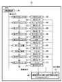
デジタルタコグラフ11は、車両20に搭載される。デジタルタコグラフ11は、インタフェースユニット40と、CPUユニット60とを備える。インタフェースユニット40及びCPUユニット60は、不図示のパターン回路基板と、このパターン回路基板に実装された抵抗やダイオードやIC(Integrated Circuit)などによって実現される。インタフェースユニット40とCPUユニット60とは、電源ケーブルや接続ケーブルによって電気的に接続されている。なお、本実施形態では、デジタルタコグラフ11がインタフェースユニット40とCPUユニット60とに分割されてケーブルで接続された例が説明されるが、インタフェースユニット40とCPUユニット60とが一体とされてもよい。 The
インタフェースユニット40は、車速情報入力部41と、回転数情報入力部42と、位置情報入力部43と、操作情報入力部51と、環境センサ44と、クロックモジュール45と、インタフェース回路46と、電源入力部47と、電源回路48とを備える。 The
電源入力部47は、車両20に搭載されたバッテリ22と、ケーブルやリード線などを用いて電気的に接続されている。電源回路48は、回路基板のパターンにより電源入力部47と電気的に接続されている。すなわち、電源回路48には、バッテリ22から直流電圧が供給される。電源回路48は、入力した直流電圧を安定した所定の定電圧に変換して出力する回路である。電源回路48は、DC−DCコンバータやレギュレータなどで構成され、5Vや3.3Vの直流電圧を出力する。後述の各回路は、電源回路48が出力した直流電圧により駆動される。なお、図2では、煩雑になるのを避けるため、電源回路48から各回路への給電線の図示が省略されている。 The
車速情報入力部41は、車両20に搭載された車速センサ23と、ケーブルやリード線などを用いて電気的に接続されている。車速情報入力部41は、車速センサ23から車速情報を入力される。車速情報入力部41は、回路基板のパターンによりインタフェース回路46と電気的に接続されている。 The vehicle speed
回転数情報入力部42は、車両20に搭載された回転数センサ24と、ケーブルやリード線などを用いて電気的に接続されている。回転数情報入力部42は、回転数センサ24から回転数情報を入力される。回転数情報入力部42は、回路基板のパターンによりインタフェース回路46と電気的に接続されている。 The rotation speed
位置情報入力部43は、車両20が備えるアンテナ21と、ケーブルやリード線などを用いて電気的に接続されている。位置情報入力部43は、アンテナ21を介して通信衛星13(図1)から位置情報を入力される。位置情報入力部43は、回路基板のパターンによりインタフェース回路46と電気的に接続されている。 The position
操作情報入力部51は、上述の第1センサ31A〜第10センサ31Jに対応して設けられた第1入力部51A〜第10入力部51Jを備える。 The operation
第1入力部51Aは、車両20に搭載された第1センサ31Aと、ケーブルやリード線などを用いて電気的に接続される。第1入力部51Aは、第1センサ31Aから負荷情報を入力される。第1入力部51Aは、回路基板のパターンによりインタフェース回路46と電気的に接続されている。 The
第2入力部51Bは、車両20に搭載された第2センサ31Bと、ケーブルやリード線などを用いて電気的に接続される。第2入力部51Bは、第2センサ31Bからステアリング角度情報を入力される。第2入力部51Bは、回路基板のパターンによりインタフェース回路46と電気的に接続されている。 The
第3入力部51Cは、車両20に搭載された第3センサ31Cと、ケーブルやリード線などを用いて電気的に接続される。第3入力部51Cは、第3センサ31Cからブレーキペダル情報を入力される。第3入力部51Cは、回路基板のパターンによりインタフェース回路46と電気的に接続されている。 The third input unit 51C is electrically connected to the
第4入力部51Dは、車両20に搭載された第4センサ31Dと、ケーブルやリード線などを用いて電気的に接続される。第4入力部51Dは、第4センサ31Dからアクセルペダル情報を入力される。第4入力部51Dは、回路基板のパターンによりインタフェース回路46と電気的に接続されている。 The fourth input unit 51D is electrically connected to the
第5入力部51Eは、車両20に搭載された第5センサ31Eと、ケーブルやリード線などを用いて電気的に接続される。第5入力部51Eは、第5センサ31Eからサイドブレーキ情報を入力される。第5入力部51Eは、回路基板のパターンによりインタフェース回路46と電気的に接続されている。 The fifth input unit 51E is electrically connected to the
第6入力部51Fは、車両20に搭載された第6センサ31Fと、ケーブルやリード線などを用いて電気的に接続される。第6入力部51Fは、第6センサ31Fからギア位置情報を入力される。第6入力部51Fは、回路基板のパターンによりインタフェース回路46と電気的に接続されている。 The
第7入力部51Gは、車両20に搭載された第7センサ31Gと、ケーブルやリード線などを用いて電気的に接続される。第7入力部51Gは、第7センサ31Gからライト情報を入力される。第7入力部51Gは、回路基板のパターンによりインタフェース回路46と電気的に接続されている。 The seventh input unit 51G is electrically connected to the
第8入力部51Hは、車両20に搭載された第8センサ31Hと、ケーブルやリード線などを用いて電気的に接続される。第8入力部51Hは、第8センサ31Hからウインカ情報を入力される。第8入力部51Hは、回路基板のパターンによりインタフェース回路46と電気的に接続されている。 The eighth input unit 51H is electrically connected to the
第9入力部51Iは、車両20に搭載された第9センサ31Iと、ケーブルやリード線などを用いて電気的に接続される。第9入力部51Iは、第9センサ31Iからドアロック情報を入力される。第9入力部51Iは、回路基板のパターンによりインタフェース回路46と電気的に接続されている。 The ninth input unit 51I is electrically connected to the
第10入力部51Jは、車両20に搭載された第10センサ31Jと、ケーブルやリード線などを用いて電気的に接続される。第10入力部51Jは、第10センサ31Jからワイパ情報を入力される。第10入力部51Jは、回路基板のパターンによりインタフェース回路46と電気的に接続されている。 The
環境センサ44は、図4に示されるように、気圧を検出する気圧センサ81(第1検出部)と、温度を検出する温度センサ82(第2検出部)と、湿度を検出する湿度センサ83(第3検出部)と、空気中の所定の成分の有無や濃度を検出するガスセンサ84(第4検出部)とを備える。ガスセンサ84は、例えば、車内の空気に含まれる揮発性有機化合物、アルコール、二酸化炭素などを検出する。環境センサ44には、例えば、BOSCH(商標)社製のBME680を用いることができる。 As shown in FIG. 4, the
クロックモジュール45は、時刻情報を出力するICである。例えば、MAXIM INTEGRATED(商標)社のDS3231をクロックモジュール45として使用することができる。クロックモジュール45は、回路基板のパターンによりインタフェース回路46と電気的に接続されている。 The
インタフェース回路46は、入力する信号を、後述のCPU61に入力可能な信号に変換する回路である。図面が煩雑になるのを避けるため図2では1個のインタフェース回路46が示されているが、インタフェース回路46は、入力する信号に合わせて設けられた複数のインタフェース回路からなる。具体的には、インタフェース回路46は、車速センサ23から入力するパルス信号を波形整形するインタフェース回路や、回転数センサ24から入力するパルス信号を波形整形するインタフェース回路など、複数のインタフェース回路からなる。 The
CPUユニット60は、図2に示されるように、CPU(Central Processing Unit)61と、記憶部62と、出力部63とを備える。 As shown in FIG. 2, the
CPU61は、演算処理を行う演算処理装置である。例えば、エイコーン(商標)社のラズベリーパイ2(RASPBERRY Pi2)がCPU61及び記憶部62として用いられる。CPU61は、車速センサ23及び回転数センサ24から入力した車速情報及び回転数情報から、車速及び回転数を演算する。この「演算」には、記憶部62に記憶された計算式による算出、及び記憶部62に記憶されたテーブルによる決定が含まれる。このテーブルには、例えば上記信号のパルス間隔に対応した車速及び回転数が対応付けて記憶されている。CPU61が制御部に相当する。 The
また、CPU61は、記憶部62への書き込み及び読み出しと、出力部63からの出力とを行う。具体的には、CPU61は、算出した車速及び回転数と、入力された位置情報、時刻情報、操作情報、及び環境情報を記憶部62に書込み、また、記憶部62からこれらの情報及び後述の識別ID(identification)を読み出し、出力部63から出力する。以下では、算出した車速及び回転数、位置情報、時刻情報、操作情報、環境情報、識別IDを運行管理情報と総称して説明がされることがある。 Further, the
記憶部62は、情報の書き込みや読出しが可能なメモリである。記憶部62は、EEPROMやRAMやROMなどである。記憶部62は、識別IDを記憶する。記憶部62は、例えばROMなどの読み出し専用メモリに識別IDを記憶する。識別IDは、各デジタルタコグラフ11にそれぞれ割り当てられる。識別IDは、識別記号に相当する。 The
また、記憶部62に記憶された車速、回転数、位置情報、時刻情報、環境情報、及び操作情報は、出力部63からの出力後、少なくとも所定の保存期間が経過するまでは上書きされずに保存される。保存期間は、通信障害が生じたとしても、出力部63から出力された運行管理情報がサーバ12に受信されるのに十分な期間として予め設定され、記憶部62に記憶された期間である。保存期間は、例えば、通信トラフィックにおけるコリジョンの発生状況から経験的に決定される。 Further, the vehicle speed, the number of revolutions, the position information, the time information, the environmental information, and the operation information stored in the
出力部63は、アンテナ21と電気的に接続されている。出力部63から出力された情報は、アンテナ21を介して外部へ送信される。アンテナ21から送信された情報は、移動体通信やインターネットなどにより、サーバ12に取得される。移動体通信及びインターネットについては公知であるので、詳しい説明は省略される。 The
出力部63からの出力は、所定の期間ごとに行われる。所定の期間は、サーバ12の性能や、運行管理システム10に用いられる車両20の台数などから決められる。すなわち、サーバ12の性能が良い場合や、車両20の台数が少ない場合は、所定の期間は短く設定される。反対に、サーバ12の性能が良くない場合や、車両20の台数が多い場合は、所定の期間は、長く設定される。所定の期間は、例えば、CPU61のクロック周波数の波数をカウントするタイマカウンタのカウント数によって決めることができる。 The output from the
サーバ12は、会社の事務所などに設置され、電話回線やインターネットなどの通信網と接続される。サーバ12は、図3に示されるように、管理ソフト71と、装置メモリ72とを備える。装置メモリ72は、サーバ12に内蔵されたものでもよいし、サーバ12に外付けされたものでもよい。 The
管理ソフト71は、各車両20から取得した運行管理情報を識別IDごとに装置メモリ72に記憶させる。 The
以下、運転手が車両20を運転するときの運行管理システム10の動作について説明がされる。 Hereinafter, the operation of the
車両20が走行することにより、車速センサ23から車速情報が車速情報入力部41に入力され、回転数センサ24から回転数情報が回転数情報入力部42に入力される。また、アンテナ21は、通信衛星13が送信する位置情報を受信する。アンテナ21が受信した位置情報は、位置情報入力部43に入力される。入力された車速情報、回転数情報、及び位置情報は、インタフェース回路46を介してCPUユニット60に入力される。 As the
また、運転手が車両20の操作部を操作することにより、操作情報が操作情報入力部51に入力される。具体的には、運転手が車両20のステアリングに力を加えてステアリングを右または左に回すことにより、負荷情報が第1入力部51Aに入力され、かつステアリング角度情報が第2入力部51Bに入力される。また、運転手が車両20のブレーキペダルやアクセルペダルを踏むことにより、ブレーキペダル情報が第3入力部51Cに入力され、アクセルペダル情報が第4入力部51Dに入力される。また、運転手が車両20のサイドブレーキを操作すると、サイドブレーキ情報が第5入力部51Eに入力される。また、運転手が車両20のギア位置を変更すると、ギア位置情報が第6入力部51Fに入力される。また、運転手が車両20のヘッドライト等のライトを点灯させると、ライト情報が第7入力部51Gに入力される。また、運転手が車両20のウインカを点灯させると、ウインカ情報が第8入力部51Hに入力される。また、運転手が車両20のドアロックを開閉すると、ドアロック情報が第9入力部51Iに入力される。また、運転手がワイパを動作させると、ワイパ情報が第10入力部51Jに入力される。 Further, when the driver operates the operation unit of the
操作情報入力部51に入力された操作情報は、インタフェース回路46を介してCPUユニット60に入力される。 The operation information input to the operation
また、環境センサ44が検出した環境情報が、インタフェース回路46を介してCPUユニット60に入力される。環境情報は、気圧センサ81が検出した気圧情報と、温度センサ82が検出した温度情報と、湿度センサ83が検出した湿度情報と、ガスセンサ84が検出したガス情報とで構成される。 Further, the environmental information detected by the
また、クロックモジュール45が出力した時刻情報が、インタフェース回路46を介してCPUユニット60に入力される。 Further, the time information output by the
CPU61は、算出した車速及び回転数、入力した位置情報、操作情報、環境情報、及び時刻情報を記憶部62に記憶させるとともに、それらの情報(運行管理情報)を、記憶部62に記憶された識別IDとともに出力部63から出力させる。出力部63から出力された運行管理情報及び識別IDは、アンテナ21から出力され、インターネット等を介してサーバ12に取得される。サーバ12は、取得した運行管理情報を、識別IDごとに装置メモリ72に記憶させる。 The
装置メモリ72に記憶された運行管理情報は、車両20の運行管理に用いられるとともに、車両20に事故が生じた場合の事故原因の解明に用いられる。例えば、運転手がアクセルペダルを強く踏んでいないのに車両20が急発進したことによって事故が生じた場合、装置メモリ72に記憶された位置情報、車速情報、時刻情報、アクセルペダル情報等が参照される。これらの情報により、アクセルペダルが強く踏み込まれていないのに車両20が急発進したことが証明される。また、運転手がブレーキペダルを強く踏み込んでいないのに車両20が急停車したことによって事故が生じた場合、装置メモリ72に記憶された位置情報、車速情報、時刻情報、ブレーキペダル情報等が参照される。これらの情報により、ブレーキペダルが強く踏み込まれていないのに車両20が急停車したことが証明される。また、運転手がステアリングに力を加えていないのに車両20が蛇行したことによって事故が生じた場合、装置メモリ72に記憶された位置情報、車速情報、時刻情報、負荷情報、ステアリング角度情報等が参照される。これらの情報により、運転手がステアリングに力を加えていないのに車両20が蛇行したことが証明される。なお、事故によってデジタルタコグラフ11からの運行管理情報の送信が停止し、サーバ12がこれらの情報を取得していない場合は、CPUユニット60の記憶部62に保存された情報が、事故原因の解明に使用される。 The operation management information stored in the
また、環境センサ44が設けられているので、事故が発生したときの気圧や温度や湿度なども、証明することができる。 Further, since the
上述のように、本実施形態では、ドライブカメラなどでは解明が困難な事故原因の解明を行うことができる。 As described above, in the present embodiment, it is possible to elucidate the cause of the accident, which is difficult to elucidate with a drive camera or the like.
また、出力部63からの出力後、予め定められた保存期間の間、運行管理情報が記憶部62に保存されるので、例え事故によって運行管理情報の送信が停止したとしても、記憶部62に記憶された運行管理情報によって事故原因の解明を行うことができる。 Further, since the operation management information is stored in the
[変形例1][Modification 1]
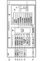
上述では、運転手が車両20の運転を行う例が説明された。本変形例では、図5に示されるように、車両20が自動運転装置90を備え、自動運転装置90が車両20の自動運転を行う例が説明される。なお、上述の実施形態と同一の構成には同一の符号が付され、説明が省略される。 In the above, an example in which the driver drives the
車両20は、自動運転装置90と、ステアリング102を回転させる第1アクチュエータ91と、ブレーキペダル103を動作させる第2アクチュエータ92と、アクセルペダル104を動作させる第3アクチュエータ93と、サイドブレーキ105を動作させる第4アクチュエータ94と、変速ギア106を動作させる第5アクチュエータ95と、ライト107を点灯させる第1点灯装置96と、ウインカ108を点灯させる第2点灯装置97と、ドアロック109を開閉させる第6アクチュエータ98と、ワイパ110を動作させる第7アクチュエータ99とを備える。 The
自動運転装置90は、第1アクチュエータ91を駆動させる駆動信号、第2アクチュエータ92を動作させる駆動信号、第3アクチュエータ93を駆動させる駆動信号、第4アクチュエータ94を駆動させる駆動信号、第5アクチュエータ95を駆動させる駆動信号、第1点灯装置96を駆動させる駆動信号、第2点灯装置97を駆動させる駆動信号、第6アクチュエータ98を駆動させる駆動信号、第7アクチュエータ99を駆動させる駆動信号を出力する。自動運転装置90は、駆動信号を出力することにより、ステアリング102を回転させ、ブレーキペダル103を動作させ、アクセルペダル104を動作させ、サイドブレーキ105を動作させ、変速ギア106の位置を変更させ、ライト107を点灯させ、ウインカ108を点灯させ、ドアロック109を開閉させ、ワイパ110を動作させて車両20を走行させる。 The automatic driving device 90 includes a drive signal for driving the
第2センサ31Bはステアリング102に対して設けられ、第3センサ31Cはブレーキペダル103に対して設けられ、第4センサ31Dはアクセルペダル104に対して設けられ、第5センサ31Eはサイドブレーキ105に対して設けられ、第6センサ31Fは変速ギア106に対して設けられ、第7センサ31Gはライト107に対して設けられ、第8センサ31Hはウインカ108に対して設けられ、第9センサ31Iはドアロック109に対して設けられ、第10センサ31Jはワイパ110に対して設けられる。 The
第2センサ31B〜第9センサ31Iが検出した操作情報は、デジタルタコグラフ11が備える操作情報入力部51に入力される。また、自動運転装置90が出力した駆動信号はデジタルタコグラフ11が備える駆動信号入力部49に入力される。 The operation information detected by the
デジタルタコグラフ11のCPU61は、入力された駆動信号を自動運転情報として記憶部62に記憶させ、また、入力された操作情報等とともに自動運転情報を出力部63から出力させる。自動運転情報は、例えば、どの操作部をどのように動作させるかを判別する情報である。具体的には、自動運転情報は、「ステアリング102を左に10度回転させる」、アクセルペダル104を15度動作させる」、「左ウインカを点灯させる」、「変速ギア106を2速の位置に動かす」などの情報である。 The
出力部63から出力された自動運転情報、運行管理情報、及び識別IDは、インターネット等を介してサーバ12に取得される。サーバ12は、取得した自動運転情報及び運行管理情報を識別IDと対応付けて装置メモリ72に記憶させる。 The automatic operation information, operation management information, and identification ID output from the
事故が生じた場合、装置メモリ72に記憶された自動運転情報及び運行管理情報が事故原因の解明に使用される。具体的に説明すると、事故原因が自動運転装置90にあるのか、車両20にあるのかが判断及び証明される。例えば、自動運転装置90がステアリング102を駆動させる駆動信号を出力していないも拘わらずステアリング102が動作したことが事故原因である場合、その事実を証明することができる。また、車両20が自動運転装置90からの駆動信号通りに走行していた場合、自動運転装置90のプログラムの不具合などが事故原因であり、その事実を証明することができる。 When an accident occurs, the automatic operation information and the operation management information stored in the
上述のように、本変形例では、自動運転装置90を搭載した車両20において事故が生じた場合に、事故原因が自動運転装置90にあるのか、車両20にあるのかを証明することができる。 As described above, in the present modification, when an accident occurs in the
また、事故が生じたときに自動運転装置90が動作していたか否かも、容易に証明することができる。 In addition, it can be easily proved whether or not the automatic driving device 90 was operating when the accident occurred.
[変形例2][Modification 2]
本変形例では、CPU61が、入力された加速度情報から、「急ハンドル」、「急加速」、及び「急ブレーキ」であるか否かを判断する例が説明される。 In this modification, an example of determining whether or not the
車両20は、図6に示されるように、加速度センサ25を備える。加速度センサ25は、例えば姿勢制御システムの一部として車両20に設けられる。本変形例では、加速度センサ25は、圧電素子などを用いた3軸の加速度センサである。加速度センサ25には、ジャイロセンサも含まれる。加速度センサ25は、加速度情報を出力する。なお、図6では、図面の簡略化のため、第1センサ31A〜第10センサ31Jがまとめてセンサ31として示されている。 The
デジタルタコグラフ11は、加速度センサ25から加速度情報が入力される加速度情報入力部53を備える。加速度情報入力部53は、加速度センサ25と、ケーブルやリード線などを用いて電気的に接続される。加速度情報入力部53は、回路基板のパターンによりインタフェース回路46と電気的に接続されている。加速度情報は、加速度情報入力部53及びインタフェース回路46を介してCPUユニット60に入力される。 The
CPU61は、加速度センサ25から入力された加速度情報及び操作情報から「急ハンドル」、「急ブレーキ」、及び「急加速」を判断する。例えば、CPU61は、車両20の幅方向における加速度が記憶部62に予め記憶された判定値以上である場合に、「急ハンドル」と判断する。また、CPU61は、車両20の前方向における加速度が記憶部62に予め記憶された判定値以上である場合に、「急加速」と判断する。また、CPU61は、例えば、車両20の後方向における加速度が記憶部62に予め記憶された判定値以上である場合に、「急ブレーキ」と判断する。 The
CPU61は、「急ハンドル」と判断すると、「急ハンドル」を示す注意情報を出力部63から出力させる。CPU61は、「急ブレーキ」と判断すると、「急ブレーキ」を示す注意情報を出力部63から出力させる。CPU61は、「急加速」と判断すると、「急加速」を示す注意情報を出力部63から出力させる。CPU61は、「障害物」と判断すると、「障害物」を示す注意情報を出力部63から出力させる。 When the
出力部63から出力された注意情報は、サーバ12に取得される。サーバ12は、取得した注意情報を装置メモリ72に記憶させる。装置メモリ72に記憶された注意情報は、車両20の運行管理に使用される。 The caution information output from the
本変形例では、運転手が危険な運転を行ったか否かを確認することができる。 In this modified example, it is possible to confirm whether or not the driver has performed dangerous driving.
本変形例では、デジタルタコグラフ11に加速度情報入力部53が設けられた例が説明された。しかしながら、デジタルタコグラフ11に加速度センサ25が直接設けられていてもよい。その場合、インタフェース回路46が加速度情報入力部に相当する。 In this modified example, an example in which the acceleration
また、本変形例では、加速度情報から「急ハンドル」等が判定される例が説明された。しかしながら、加速度情報、操作情報、速度情報を総合して、「急ハンドル」等が判定されてもよい。 Further, in this modified example, an example in which "sudden steering wheel" or the like is determined from the acceleration information has been described. However, the "sudden steering wheel" or the like may be determined by integrating the acceleration information, the operation information, and the speed information.
[変形例3][Modification 3]
本変形例では、図7に示されるように、デジタルタコグラフ11が状態情報入力部52をさらに備える例が説明される。状態情報入力部52は、車両20の状態を示す状態情報が入力される入力部である。なお、図7では、図面の簡略化のため、第1センサ31A〜第10センサ31Jがまとめてセンサ31として示されている。 In this modification, as shown in FIG. 7, an example in which the
車両20は、第11センサ32A、第12センサ32B、及び第13センサ32Cを備える。 The
第11センサ32Aは、車両20に搭載されている油圧システムの油圧を検出する油圧センサである。第11センサ32Aは、油圧システムの油圧を示す油圧情報を出力する。 The
第12センサ32Bは、車両20のエンジンンの冷却水の温度を検出する温度センサである。第12センサ32Bは、冷却水の温度を示す水温情報を出力する。 The
第13センサ32Cは、車両20の燃料タンクに存在する燃料の残量を検出するセンサである。第13センサ32Cは、燃料の残量を示す燃料情報を出力する。 The thirteenth sensor 32C is a sensor that detects the remaining amount of fuel existing in the fuel tank of the
上述の油圧情報、水温情報、及び燃料情報は、車両20の状態を示す状態情報である。 The above-mentioned oil pressure information, water temperature information, and fuel information are state information indicating the state of the
状態情報入力部52は、第11センサ32Aから油圧情報が入力される第11入力部52Aと、第12センサ32Bから水温情報が入力される第12入力部52Bと、第13センサ32Cから燃料情報が入力される第13入力部52Cとを備える。第11入力部52Aは、ケーブルやリード線などを用いて第11センサ32Aと電気的に接続されている。第12入力部52Bは、ケーブルやリード線などを用いて第12センサ32Bと電気的に接続されている。第13入力部52Cは、ケーブルやリード線などを用いて第13センサ32Cと電気的に接続されている。第11入力部52A、第12入力部52B、及び第13入力部52Cは、回路基板のパターンによりインタフェース回路46と電気的に接続されている。油圧情報、水温情報、及び燃料情報は、状態情報入力部52(第11入力部52A、第12入力部52B、第13入力部52C)及びインタフェース回路46を介してCPUユニット60に入力される。 The state
CPU61は、状態情報入力部52から入力した油圧情報、水温情報、及び燃料情報などの状態情報を記憶部62に記憶させる。また、CPU61は、位置情報や操作情報などの他の情報とともに、状態情報を出力部63から出力させる。出力部63から出力された状態情報は、サーバ12に取得される。サーバ12は、取得した状態情報を、識別IDや操作情報とともに装置メモリ72に記憶させる。 The
本変形例では、操作情報とともに、車両20の状態を示す状態情報が装置メモリ72に記憶されるから、事故などが生じた際に、事故発生時の車両20の状態を確認することができる。 In this modification, since the state information indicating the state of the
なお、上述の実施形態や変形例において、第1センサ31A〜第10センサ31J、及び第11センサ32A〜第13センサ32Cは、車両20に元から搭載されているセンサが流用されてもよいし、デジタルタコグラフ11の搭載時に車両20に新たに付設されてもよい。 In the above-described embodiment and modification, the sensors originally mounted on the
10・・・運行管理システム
11・・・デジタルタコグラフ
12・・・サーバ
20・・・車両
23・・・車速センサ
24・・・回転数センサ
31A・・第1センサ
31B・・第2センサ
31C・・第3センサ
31D・・第4センサ
31E・・第5センサ
31F・・第6センサ
31G・・第7センサ
31H・・第8センサ
31I・・第9センサ
31J・・第10センサ
32A・・第11センサ
32B・・第12センサ
32C・・第13センサ
41・・・車速情報入力部
42・・・回転数情報入力部
43・・・位置情報入力部
44・・・環境センサ
45・・・クロックモジュール
49・・・駆動信号入力部
51・・・操作情報入力部
51A・・第1入力部
51B・・第2入力部
51C・・第3入力部
51D・・第4入力部
51E・・第5入力部
51F・・第6入力部
51G・・第7入力部
51H・・第8入力部
51I・・第9入力部
51J・・第10入力部
52・・・状態情報入力部
52A・・第11入力部
52B・・第12入力部
52C・・第13入力部
53・・・加速度情報入力部
61・・CPU(制御部)
62・・・記憶部
63・・・出力部
72・・・装置メモリ
81・・・気圧センサ(第1検出部)
82・・・温度センサ(第2検出部)
83・・・湿度センサ(第3検出部)
84・・・ガスセンサ(第4検出部)
90・・・自動運転装置
10 ...
62 ...
82 ... Temperature sensor (second detector)
83 ... Humidity sensor (3rd detector)
84 ... Gas sensor (4th detector)
90 ... Automatic driving device
Claims (11)
Translated fromJapanese位置情報が入力される位置情報入力部と、
自動運転装置が車両を操作するために出力する信号を駆動信号として、当該駆動信号が入力される駆動信号入力部と、
上記駆動信号によって動作した操作部の実際の操作量を検出するセンサから操作情報が入力される操作情報入力部と、
識別記号が記憶される記憶部と、
情報を外部へ出力する出力部と、
上記車速情報、上記位置情報、上記操作情報、及び上記識別記号を上記出力部から出力させる制御部と、を備え、
上記制御部は、上記駆動信号に基いて生成され、かつ当該駆動信号が上記操作部をどのように動作させるかを判別可能な自動運転情報を上記操作情報とともに上記出力部から出力させる、情報を送信する装置。Vehicle speed information input unit where vehicle speed information is input, and
The location information input section where location information is input and
A drive signal input unit to which the drive signal is input, using a signal output by the automatic driving device to operate the vehicle as a drive signal,
An operation information input unit in which operation information is input from a sensor that detects the actual operation amount ofthe operation unit operated by the above drive signal, and
A storage unit that stores the identification symbol and
An output unit that outputs information to the outside and
The vehicle speed information, the position information, the operation information, and the control unit for outputting the identification symbol from the output unit are provided.
The control unit outputs information that is generated based on the drive signal and that can determine how the drive signal operates the operation unit from the output unit together with the operation information. A device to transmit.
ステアリングに加えられた力を検出する第1センサから上記操作情報が入力する第1入力部と、
上記ステアリングの回転角度を検出する第2センサから上記操作情報が入力する第2入力部と、
ブレーキペダルの操作量を検出する第3センサから上記操作情報が入力する第3入力部と、
アクセルペダルの操作量を検出する第4センサから上記操作情報が入力する第4入力部と、
サイドブレーキの操作を検出する第5センサから上記操作情報が入力する第5入力部と、
変速ギアの位置を検出する第6センサから上記操作情報が入力する第6入力部と、
ライトの点灯、消灯を検出する第7センサから上記操作情報が入力する第7入力部と、
ウインカの点灯、消灯を検出する第8センサから上記操作情報が入力する第8入力部と、
ドアロックの開閉を検出する第9センサから上記操作情報が入力する第9入力部と、
ワイパの動作を検出する第10センサから上記操作情報が入力する第10入力部と、
のうち、少なくとも1つを有する請求項1に記載の情報を送信する装置。The above operation information input unit
The first input unit that inputs the above operation information from the first sensor that detects the force applied to the steering, and
A second input unit for inputting the operation information from the second sensor that detects the rotation angle of the steering wheel, and
A third input unit that inputs the above operation information from the third sensor that detects the operation amount of the brake pedal, and
The 4th input unit where the above operation information is input from the 4th sensor that detects the operation amount of the accelerator pedal, and
The fifth input unit, in which the above operation information is input from the fifth sensor that detects the operation of the side brake,
The sixth input unit, in which the above operation information is input from the sixth sensor that detects the position of the transmission gear, and
The 7th input unit where the above operation information is input from the 7th sensor that detects the on / off of the light, and
The 8th input unit where the above operation information is input from the 8th sensor that detects the lighting and extinguishing of the blinker, and
The 9th input unit, which inputs the above operation information from the 9th sensor that detects the opening and closing of the door lock,
The 10th input unit where the above operation information is input from the 10th sensor that detects the operation of the wiper, and
A device for transmitting the information according to claim 1, which has at least one of them.
上記制御部は、上記環境センサが出力したした環境情報を上記操作情報とともに上記出力部から出力させる請求項1または2に記載の情報を送信する装置。At least one of a first detection unit that detects atmospheric pressure, a second detection unit that detects temperature, a third detection unit that detects humidity, and a fourth detection unit that detects air components in the vehicle. Further equipped with an environmental sensor that has
The control unit is a device that transmits the information according toclaim 1 or 2 in which the environmental information output by the environmental sensor is output from the output unit together with the operation information.
車両の冷却水の水温を示す水温情報が入力される第12入力部と、
車両の燃料残量を示す燃料情報が入力される第13入力部と、のうち少なくとも1つを有する状態情報入力部をさらに備え、
上記制御部は、上記状態情報入力部から入力された状態情報を上記出力部から出力させる請求項1から3のいずれかに記載の情報を送信する装置。The eleventh input unit, which inputs the flood control information indicating the flood control of the flood control system mounted on the vehicle, and
The twelfth input section where water temperature information indicating the water temperature of the vehicle cooling water is input, and
It further includes a thirteenth input unit for inputting fuel information indicating the remaining fuel amount of the vehicle, and a state information input unit having at least one of them.
The control unit is a device that transmits the information according to anyone of claims 1 to 3 for outputting the state information input from the state information input unit from the output unit.
上記制御部は、上記加速度情報及び上記操作情報から急ハンドルと急加速と急ブレーキと障害物とのうち少なくとも1つを判断する判断処理を行い、当該判断処理において急ハンドル、急加速、急ブレーキ、或いは障害物と判断したことを条件に、注意情報を上記出力部から出力させる請求項2から4のいずれかに記載の情報を送信する装置。It also has an acceleration information input unit that inputs acceleration information from the acceleration sensor.
The control unit performs a judgment process for determining at least one of a sudden steering wheel, a sudden acceleration, a sudden braking, and an obstacle from the acceleration information and the operation information, and in the judgment process, the sudden steering wheel, the sudden acceleration, and the sudden braking Or, a device for transmitting the information according to any one ofclaims 2 to 4 , which outputs caution information from the output unit on condition that it is determined to be an obstacle.
上記制御部は、上記時刻情報を上記操作情報とともに上記出力部から出力させる請求項1から5のいずれかに記載の情報を送信する装置。It also has a clock module that outputs time information.
The control unit is a device that transmits the information according to anyone of claims 1 to 5 for outputting the time information together with the operation information from the output unit.
上記情報を送信する装置が出力した情報及び上記識別記号を取得するサーバと、を備える管理システム。A device that transmits a plurality of pieces of information according to any one of claims 1 to7.
A management system including a server that acquires information output by a device that transmits the above information and the identification symbol.
識別記号が記憶される記憶部と、
情報を外部へ出力する出力部と、
上記駆動信号に基いて生成され、かつ当該駆動信号が上記駆動部をどのように動作させるかを判別可能な自動運転情報、上記操作情報、及び上記識別記号を上記出力部から出力させる制御部と、を備えた装置。An information input unit in which operation information is input from a sensor that detects the actual amount of operation of the drive unit driven by the drive signal output by the automatic driving device.
A storage unit that stores the identification symbol and
An output unit that outputs information to the outside and
With the automatic operation information generated based on the drive signal and capable of determining how the drive signal operates , the operation information, and the control unit that outputs the identification symbol from the output unit. A device equipped with.
上記装置が出力した自動運転情報、上記操作情報、及び上記識別記号が入力されるサーバと、を備え、
上記サーバは、上記識別記号と対応付けて上記自動運転情報及び上記操作情報をメモリに記憶させるシステム。The device according to claim10 and
The automatic operation information output by the device, the operation information, and the server into which the identification symbol is input are provided.
The server is a system that stores the automatic operation information and the operation information in a memory in association with the identification symbol.
Priority Applications (1)
| Application Number | Priority Date | Filing Date | Title |
|---|---|---|---|
| JP2016166245AJP6853563B2 (en) | 2016-08-26 | 2016-08-26 | Equipment for transmitting information and management system |
Applications Claiming Priority (1)
| Application Number | Priority Date | Filing Date | Title |
|---|---|---|---|
| JP2016166245AJP6853563B2 (en) | 2016-08-26 | 2016-08-26 | Equipment for transmitting information and management system |
Publications (3)
| Publication Number | Publication Date |
|---|---|
| JP2018032352A JP2018032352A (en) | 2018-03-01 |
| JP2018032352A5 JP2018032352A5 (en) | 2018-04-12 |
| JP6853563B2true JP6853563B2 (en) | 2021-03-31 |
Family
ID=61304638
Family Applications (1)
| Application Number | Title | Priority Date | Filing Date |
|---|---|---|---|
| JP2016166245AActiveJP6853563B2 (en) | 2016-08-26 | 2016-08-26 | Equipment for transmitting information and management system |
Country Status (1)
| Country | Link |
|---|---|
| JP (1) | JP6853563B2 (en) |
Families Citing this family (2)
| Publication number | Priority date | Publication date | Assignee | Title |
|---|---|---|---|---|
| JP6962566B2 (en)* | 2018-03-06 | 2021-11-05 | 株式会社パインベース | Information transmitters, programs, and management systems |
| JP6964649B2 (en)* | 2019-12-09 | 2021-11-10 | 本田技研工業株式会社 | Vehicle control system |
Family Cites Families (7)
| Publication number | Priority date | Publication date | Assignee | Title |
|---|---|---|---|---|
| JP2000194895A (en)* | 1998-12-25 | 2000-07-14 | Tmp:Kk | Vehicle operation management system and digital vehicle operation recorder |
| JP5938197B2 (en)* | 2011-12-01 | 2016-06-22 | 矢崎エナジーシステム株式会社 | Travel data transfer system |
| JP5972201B2 (en)* | 2013-03-22 | 2016-08-17 | ヤンマー株式会社 | Maneuvering system |
| JP6265525B2 (en)* | 2013-10-08 | 2018-01-24 | 東芝情報システム株式会社 | Driving related information sharing system and driver terminal |
| EP3223256B1 (en)* | 2014-11-17 | 2021-11-17 | Hitachi Astemo, Ltd. | Automatic driving system |
| JP6521803B2 (en)* | 2014-12-09 | 2019-05-29 | 株式会社Soken | Automatic operation control device, footrest, automatic operation control method, and operation information output method |
| JP6451282B2 (en)* | 2014-12-12 | 2019-01-16 | 富士通株式会社 | Analysis data generation program for driving operation, analysis data generation method, poster, and information processing apparatus |
- 2016
- 2016-08-26JPJP2016166245Apatent/JP6853563B2/enactiveActive
Also Published As
| Publication number | Publication date |
|---|---|
| JP2018032352A (en) | 2018-03-01 |
Similar Documents
| Publication | Publication Date | Title |
|---|---|---|
| JP5820190B2 (en) | On-board device for event monitoring | |
| KR100267026B1 (en) | Recording of operational events in an automotive vehicle | |
| US20080316010A1 (en) | Recording system and method for capturing images of driving conditions and driving images identification method | |
| US20170148237A1 (en) | In-vehicle control device and in-vehicle recording system | |
| US20110254676A1 (en) | Drive recorder | |
| US20110304447A1 (en) | Drive recorder | |
| US11269326B2 (en) | Monitoring and tracking mode of operation of vehicles to determine services | |
| US20210272398A1 (en) | Travel control device, travel control system, travel control method, and tire testing device | |
| CA3152568A1 (en) | After-market vehicle copilot device | |
| CN102982589B (en) | A kind of vehicle information recorder based on car load network and recording method thereof | |
| JP6853563B2 (en) | Equipment for transmitting information and management system | |
| CN111464797A (en) | Driving assistance apparatus, method, vehicle, and storage medium | |
| CA2734423C (en) | Environment activated automatic shut-off switch system and method | |
| JP3217361U (en) | In-vehicle information provider | |
| SE1150301A1 (en) | Vehicles with a tachograph | |
| JP6251704B2 (en) | On-board device for recording operation information | |
| WO2019111336A1 (en) | Digital tachograph, and operation management system | |
| JP6273811B2 (en) | Driving status recording system, driving status recording device | |
| CN113646818A (en) | Apparatus and method for warning following vehicle not maintaining safe distance | |
| JP6921302B2 (en) | Notification system and notification method | |
| JP7568483B2 (en) | DRIVER STATE ESTIMATION DEVICE, DRIVER STATE ESTIMATION PROGRAM, AND DAILY DRIVE REPORT GENERATION METHOD | |
| JP6186195B2 (en) | Intermediate connector | |
| KR200348621Y1 (en) | Monitoring system for vehicles | |
| JP2018032352A5 (en) | Information transmission device and management system | |
| CA2676746A1 (en) | Motor vehicle surveillance system |
Legal Events
| Date | Code | Title | Description |
|---|---|---|---|
| A521 | Request for written amendment filed | Free format text:JAPANESE INTERMEDIATE CODE: A523 Effective date:20180220 | |
| A621 | Written request for application examination | Free format text:JAPANESE INTERMEDIATE CODE: A621 Effective date:20190625 | |
| A711 | Notification of change in applicant | Free format text:JAPANESE INTERMEDIATE CODE: A711 Effective date:20191016 | |
| A977 | Report on retrieval | Free format text:JAPANESE INTERMEDIATE CODE: A971007 Effective date:20200604 | |
| A131 | Notification of reasons for refusal | Free format text:JAPANESE INTERMEDIATE CODE: A131 Effective date:20200721 | |
| A521 | Request for written amendment filed | Free format text:JAPANESE INTERMEDIATE CODE: A523 Effective date:20200916 | |
| TRDD | Decision of grant or rejection written | ||
| A01 | Written decision to grant a patent or to grant a registration (utility model) | Free format text:JAPANESE INTERMEDIATE CODE: A01 Effective date:20210202 | |
| A61 | First payment of annual fees (during grant procedure) | Free format text:JAPANESE INTERMEDIATE CODE: A61 Effective date:20210305 | |
| R150 | Certificate of patent or registration of utility model | Ref document number:6853563 Country of ref document:JP Free format text:JAPANESE INTERMEDIATE CODE: R150 | |
| R250 | Receipt of annual fees | Free format text:JAPANESE INTERMEDIATE CODE: R250 | |
| R250 | Receipt of annual fees | Free format text:JAPANESE INTERMEDIATE CODE: R250 |