JP6852352B2 - Loop heat pipes and electronics - Google Patents
Loop heat pipes and electronicsDownload PDFInfo
- Publication number
- JP6852352B2 JP6852352B2JP2016217241AJP2016217241AJP6852352B2JP 6852352 B2JP6852352 B2JP 6852352B2JP 2016217241 AJP2016217241 AJP 2016217241AJP 2016217241 AJP2016217241 AJP 2016217241AJP 6852352 B2JP6852352 B2JP 6852352B2
- Authority
- JP
- Japan
- Prior art keywords
- flow path
- metal sheet
- working fluid
- groove
- loop
- Prior art date
- Legal status (The legal status is an assumption and is not a legal conclusion. Google has not performed a legal analysis and makes no representation as to the accuracy of the status listed.)
- Expired - Fee Related
Links
Images


Landscapes
- Cooling Or The Like Of Semiconductors Or Solid State Devices (AREA)
- Cooling Or The Like Of Electrical Apparatus (AREA)
Description
Translated fromJapanese本発明は、ループヒートパイプ及び電子機器に関する。 The present invention relates to loop heat pipes and electronic devices.
スマートフォンやタブレット端末等のような小型で薄い電子機器の普及に伴い、これらの電子機器に内蔵されているCPU(Central Processing Unit)等の発熱部品を冷却する様々な方法が提案されている。 With the widespread use of small and thin electronic devices such as smartphones and tablet terminals, various methods for cooling heat-generating components such as CPUs (Central Processing Units) built in these electronic devices have been proposed.
発熱部品を冷却する方法としては、例えば、熱伝導率が良好な金属板や熱拡散シートで発熱部品の熱を外部に輸送する方法がある。但し、この方法では、輸送できる熱が金属板や熱拡散シートの熱伝導率によって制限されてしまう。例えば、熱拡散シートとして使用されるグラファイトシートの熱伝導率は500W/mK〜1500W/mK程度であり、この程度の熱伝導率では発熱部品の発熱量が多くなったときに発熱部品を冷却するのが難しくなってしまう。 As a method of cooling the heat-generating component, for example, there is a method of transporting the heat of the heat-generating component to the outside by a metal plate or a heat diffusion sheet having good thermal conductivity. However, in this method, the heat that can be transported is limited by the thermal conductivity of the metal plate or the heat diffusion sheet. For example, the thermal conductivity of a graphite sheet used as a heat diffusion sheet is about 500 W / mK to 1500 W / mK, and at this level of thermal conductivity, the heat-generating component is cooled when the amount of heat generated by the heat-generating component increases. Will be difficult.
そこで、発熱部品の熱を積極的に移動し、発熱部品を冷却するデバイスとしてヒートパイプが検討されている。 Therefore, a heat pipe is being studied as a device that positively transfers the heat of the heat-generating component and cools the heat-generating component.
ヒートパイプは、作動流体の相変化を利用して熱を輸送するデバイスであって、上記の熱拡散シートよりも効率的な熱輸送ができる。例えば、直径が3mmのヒートパイプは、1500W/mK〜2500W/mK程度に相当する大きな熱伝導率を示す。 The heat pipe is a device that transports heat by utilizing the phase change of the working fluid, and can transport heat more efficiently than the above-mentioned heat diffusion sheet. For example, a heat pipe having a diameter of 3 mm exhibits a large thermal conductivity corresponding to about 1500 W / mK to 2500 W / mK.
ヒートパイプには幾つかの種類がある。ループヒートパイプは、発熱部品の熱により作動流体を気化させる蒸発器と、気化した作動流体を冷却して液化する凝縮器とを備える。そして、蒸発器と凝縮器は、蒸気管や液管等のパイプによってループ状に接続されており、その内部に作動流体が封入されている。 There are several types of heat pipes. The loop heat pipe includes an evaporator that vaporizes the working fluid by the heat of the heat generating component and a condenser that cools and liquefies the vaporized working fluid. The evaporator and the condenser are connected in a loop by a pipe such as a steam pipe or a liquid pipe, and a working fluid is sealed in the loop.
ループヒートパイプは作動流体が流れる方向が一方向となるため、液相の作動流体とその蒸気が管内を往復するヒートパイプと比較して作動流体が受ける抵抗が少なく、効率的に熱輸送を行うことができる。 Since the loop heat pipe has a unidirectional flow of the working fluid, the working fluid receives less resistance than the heat pipe in which the liquid phase working fluid and its vapor reciprocate in the pipe, and efficiently transports heat. be able to.
しかしながら、薄型化された電子機器にループヒートパイプを搭載する場合、電子機器の厚さに合わせて前述の蒸発器、凝縮器、液管、及び蒸発器を扁平に潰さなければならない。その結果、液管や蒸気管のレイアウトによってはこれらの管を作動流体が流れ難くなり、ループヒートパイプの熱輸送の性能が低下するおそれがある。 However, when the loop heat pipe is mounted on a thin electronic device, the above-mentioned evaporator, condenser, liquid tube, and evaporator must be flattened according to the thickness of the electronic device. As a result, depending on the layout of the liquid pipe and the steam pipe, it becomes difficult for the working fluid to flow through these pipes, and the heat transport performance of the loop heat pipe may deteriorate.
開示の技術は、上記に鑑みてなされたものであって、ループヒートパイプの熱輸送の性能を向上させることを目的とする。 The disclosed technique has been made in view of the above and aims to improve the heat transport performance of the loop heat pipe.
一つの側面によれば、第1の金属シート、第2の金属シート、及び第3の金属シートが順に積層された積層体と、前記第1の金属シートと前記第2の金属シートとの間に設けられ、第1の作動流体が封入されたループ状の第1の流路と、前記第1の流路の途中に設けられ、前記第1の作動流体を蒸発させる第1の蒸発器と、前記第2の金属シートと前記第3の金属シートとの間に設けられ、第2の作動流体が封入されたループ状の第2の流路と、前記第2の流路の途中に設けられ、前記第2の作動流体を蒸発させる第2の蒸発器と、前記積層体の一部に設けられ、平面視で前記第1の流路と前記第2の流路のそれぞれに重なり、かつ前記第1の作動流体と前記第2の作動流体を凝縮させる凝縮器とを有し、前記第2の金属シートは、前記第1の金属シートに対向する第1の表面と、前記第3の金属シートに対向する第2の表面と、を有し、前記第1の表面に前記第1の流路を構成する第1の溝が形成され、前記第2の表面に前記第2の流路を構成する第2の溝が形成されているループヒートパイプが提供される。According to one side surface, between the first metal sheet, the second metal sheet, and the laminated body in which the third metal sheet is laminated in order, and the first metal sheet and the second metal sheet. A loop-shaped first flow path in which the first working fluid is sealed, and a first evaporator provided in the middle of the first flow path to evaporate the first working fluid. , A loop-shaped second flow path provided between the second metal sheet and the third metal sheet and filled with the second working fluid, and provided in the middle of the second flow path. A second evaporator for evaporating the second working fluid and a part of the laminated body are provided so as to overlap each other of the first flow path and the second flow path in a plan view.possess a condenser for condensing the second working fluid from the first workingfluid, said second metal sheet has a first surface facing the first metal sheet, the third A first groove having a second surface facing the metal sheet and forming the first flow path is formed on the first surface, and the second flow path is formed on the second surface. A loop heat pipe is provided in which asecond groove constituting the above is formed.
一つの側面によれば、本発明においては、第1の金属シートと第2の金属シートとの間に第1の流路を設け、かつ第2の金属シートと第3の金属シートとの間に第2の流路を設ける。このように各金属シートの異なる層間に第1の流路と第2の流路を設けるため、これらの流路が平面視で交差する場合であっても、その交差点には段差が発生しない。その結果、段差によって第1の作動流体や第2の作動流体の流れが滞るのを防止でき、ひいてはループヒートパイプの熱輸送の性能を向上させることが可能となる。 According to one aspect, in the present invention, a first flow path is provided between the first metal sheet and the second metal sheet, and between the second metal sheet and the third metal sheet. A second flow path is provided in. Since the first flow path and the second flow path are provided between the different layers of each metal sheet in this way, even when these flow paths intersect in a plan view, no step is generated at the intersection. As a result, it is possible to prevent the flow of the first working fluid and the second working fluid from being blocked by the step, and it is possible to improve the heat transport performance of the loop heat pipe.
本実施形態の説明に先立ち、本願発明者が行った検討事項について説明する。 Prior to the description of the present embodiment, the matters to be examined by the inventor of the present application will be described.
図1は、検討に使用したループヒートパイプの模式図である。 FIG. 1 is a schematic view of the loop heat pipe used in the study.
このループヒートパイプ1は、スマートフォン等の薄型の電子機器2に収容されるものであり、蒸発器3と凝縮器4とを有する。 The
蒸発器3と凝縮器4には蒸気管5と液管6とが接続されており、これらの管5、6によって作動流体Cが流れるループ状の流路が形成される。また、蒸発器3にはCPU等の発熱部品7が固着されており、その発熱部品7の熱により作動流体Cの蒸気Cvが生成される。 A
蒸気Cvは、蒸気管5を通って凝縮器4に導かれる。凝縮器4は、外気との熱交換により蒸気Cvを冷却して液化する機能を有し、外気との接触面積を増やすために板状とされる。そして、凝縮器4で液化した作動流体Cは液管6を通って再び蒸発器3に供給される。 The steam Cv is guided to the
このようにループ状の流路を作動流体Cが流れることにより、発熱部品7で発生した熱が凝縮器4に移動し、発熱部品7が冷却されることになる。 When the working fluid C flows through the loop-shaped flow path in this way, the heat generated in the
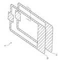
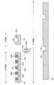
図2は、このループヒートパイプ1の分解斜視図である。 FIG. 2 is an exploded perspective view of the
図2に示すように、このループヒートパイプ1は、第1の銅シート11と第2の銅シート12とを有しており、これらを接合することにより作製される。 As shown in FIG. 2, the
図3は、図2のI-I線に沿った断面図である。 FIG. 3 is a cross-sectional view taken along the line I-I of FIG.
図3に示すように、第1の銅シート11と第2の銅シート12には、それぞれ第1の溝11aと第2の溝12aが設けられる。そして、これらの銅シート11、12を接合することにより、扁平な断面形状の蒸気管5や液管6が各溝11a、12aによって画定される。As shown in FIG. 3, the
このようなループヒートパイプ1によれば、第1の銅シート11と第2の銅シート12とを接合することにより作製されるため、スマートフォン等の薄型の電子機器2に適した薄いヒートパイプ1を得ることができる。 According to such a
但し、そのループヒートパイプ1に設けられている蒸発器3は一つのみであるため、複数の発熱部品7を備えた電子機器2においては複数の発熱部品7ごとに複数のループヒートパイプ1を用意しなければならない。 However, since only one
図4は、二つの発熱部品7を備えた電子機器2の平面図である。 FIG. 4 is a plan view of the
なお、図4において、図1で説明したのと同じ要素には図1におけるのと同じ符号を付し、以下ではその説明を省略する。 In FIG. 4, the same elements as described in FIG. 1 are designated by the same reference numerals as those in FIG. 1, and the description thereof will be omitted below.
図4の例では、二つの発熱部品7に対応して二つのループヒートパイプ1を電子機器2に設け、二つの発熱部品7の各々をループヒートパイプ1の各々の蒸発器3に固着している。 In the example of FIG. 4, two
この場合、電子機器2の小型化を図るために、電子機器2内において各ループヒートパイプ1を重ねて設けることになる。 In this case, in order to reduce the size of the
図5は、このように重ねて設けられたループヒートパイプ1の斜視図である。 FIG. 5 is a perspective view of the
図5に示すように、二つのループヒートパイプ1を重ねるレイアウトでは、これらのループヒートパイプ1同士が交差する交差点Aが発生する。その交差点Aにおいては、一方のループヒートパイプ1の蒸気管5や液管6に段差を設けることにより二つの蒸発器3を同一面内に配し、電子機器2の薄型化を図る。 As shown in FIG. 5, in the layout in which the two
しかしながら、このように段差を設けると交差点Aにおいて作動流体Cの流れが滞ってしまい、段差が設けられたループヒートパイプ1の熱輸送能力が低下してしまう。 However, if the step is provided in this way, the flow of the working fluid C is stagnant at the intersection A, and the heat transport capacity of the
しかも、この例では二つのループヒートパイプ1の凝縮器4同士が重なっているため、一方の凝縮器4の熱で他方の凝縮器4が温まってしまい、各々の凝縮器4の放熱効率が悪くなってしまう。 Moreover, in this example, since the
また、このように二つのループヒートパイプ1を交差させると次のような問題も発生する。 Further, when the two
図6は、交差点Aで発生する別の問題について説明するための断面図であって、図4のII-II線に沿う断面図に相当する。 FIG. 6 is a cross-sectional view for explaining another problem occurring at the intersection A, and corresponds to a cross-sectional view taken along the line II-II of FIG.
図6に示すように、交差点Aにおいては、二つのループヒートパイプ1の液管6同士が交差する。電子機器2の薄型化のためにはこれらの液管6同士を密着させるのが好ましいが、製造誤差等によって各液管6の間に隙間Sが生じ、その隙間Sにおける空気によって各液管6の間の熱抵抗が上昇する。 As shown in FIG. 6, at the intersection A, the
その結果、各液管6を流れる液相の作動流体Cに温度差が現れ、その作動流体Cで二つの発熱部品7を均等に冷却するのが難しくなる。 As a result, a temperature difference appears in the working fluid C of the liquid phase flowing through each
以下、本実施形態について説明する。 Hereinafter, this embodiment will be described.
(第1実施形態)
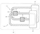
図7は、本実施形態に係る電子機器の平面図である。(First Embodiment)
FIG. 7 is a plan view of the electronic device according to the present embodiment.
この電子機器20は、スマートフォン、デジタルカメラ、及びタブレット端末等の小型の電子機器であって、筐体21とその内部に収容された第1及び第2の発熱部品22、23を有する。 The
各発熱部品22、23は、動作時に発熱するCPU等の能動素子であって、ループヒートパイプ24により冷却される。 Each of the
ループヒートパイプ24は、後述のように複数の金属シートを積層することにより作製され、いずれも平面視でループ状の第1の流路25と第2の流路26とを有する。 The
第1の流路25と第2の流路26は独立した流路であり、その各々に第1の作動流体C1と第2の作動流体C2が封入される。 The
また、第1の流路25の途中には、第1の発熱部品22に固着された第1の蒸発器31が設けられる。固着の仕方は特に限定されないが、この例では不図示のTIM(Thermal Interface Material)を介して第1の蒸発器31に第1の発熱部品22を接続する。 Further, a
第1の蒸発器31は、第1の発熱部品22の熱で第1の作動流体C1を蒸発させることにより、第1の作動流体C1の第1の蒸気Cv1を生成する。その第1の蒸気Cv1は、第1の流路25に設けられた第1の蒸気管33を通って凝縮器27に至る。 The
凝縮器27は、第1の流路25と第2の流路26の各々に重なる平面形状を有しており、外気との熱交換によって第1の作動流体C1や第2の作動流体C2を冷却してこれらを液化する。なお、外気との熱交換を促すために、凝縮器27を平面視で矩形状にし、凝縮器27の表面積を増やすのが好ましい。 The
そして、凝縮器27において液化した第1の作動流体C1は、第1の流路25に設けられた第1の液管34を通って再び第1の蒸発器31に戻る。 Then, the first working fluid C1 liquefied in the
一方、第2の流路26の途中には、第2の発熱部品23に固着された第2の蒸発器35が設けられる。固着の仕方は特に限定されず、第1の発熱部品22と同様に不図示のTIMを介して第2の蒸発器35に第2の発熱部品23を接続し得る。 On the other hand, in the middle of the
第2の蒸発器35は、第2の発熱部品23の熱で第2の作動流体C2を蒸発させることにより、第2の作動流体C2の第2の蒸気Cv2を生成する。その第2の蒸気Cv2は、第2の流路26に設けられた第2の蒸気管36を通って凝縮器27に至った後、凝縮器27で冷却されて液化する。 The
そして、凝縮器27において液化した第2の作動流体C2は、第2の流路26に設けられた第2の液管37を通って再び第2の蒸発器35に戻る。 Then, the second working fluid C2 liquefied in the
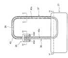
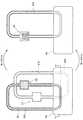
図8は、このループヒートパイプ24の斜視図である。 FIG. 8 is a perspective view of the
図8に示すように、各流路25、26は、平面視で交差点B、Cにおいて交差する。 As shown in FIG. 8, the
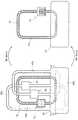
図9は、交差点Bにおけるループヒートパイプ24の分解斜視図である。 FIG. 9 is an exploded perspective view of the
図9に示すように、ループヒートパイプ24は第1〜第3の金属シート41〜43をこの順に積層した積層体44から形成される。各金属シート41〜43の材料は特に限定されないが、この例では銅シートを各金属シート41〜43として使用する。 As shown in FIG. 9, the
なお、銅シートに代えて、ステンレスシートや銅合金を材料とする銅合金シートを各金属シート41〜43として使用してもよい。 Instead of the copper sheet, a stainless sheet or a copper alloy sheet made of a copper alloy may be used as each
これらの金属シート41〜43のうち、第2の金属シート42は、第1の金属シート41に対向する第1の表面42aと、第3の金属シート43に対向する第2の表面42bとを有する。 Of these
第1の表面42aには、第1の流路25の上部内面を画定する第1の溝42xが形成される。そして、第2の表面42bには、第2の流路26の下部内面を画定する第2の溝42yが形成される。 A
また、第1の金属シート41には第1の流路25の下部内面を画定する第3の溝41xが形成され、第3の金属シート43には第2の流路26の上部内面を画定する第4の溝43xが形成される。 Further, the
これにより、このループヒートパイプ24においては、第1の金属シート41と第2の金属シート42との層間に第1の流路25が形成され、かつ第2の金属シート42と第3の金属シート43との層間に第2の流路26が形成されることになる。 As a result, in the
なお、流路25、26が潰れるのを防止するために、これらの流路の内部にリブ構造や多孔質構造を設けてもよい。 In addition, in order to prevent the
これらの流路25、26は、各金属シート41〜43の層間に形成されるため、電子機器20の薄型化を図るのに適した扁平な断面形状となる。 Since these
また、この例のように各流路25、26を設ける部位を金属シート41〜43の異なる層間とすることにより、各流路25、26に段差を設けることなしに交差点B、Cにおいて各流路25、26を交差させることができる。その結果、図4の例とは異なり、各流路25、26の段差において第1の作動流体C1や第2の作動流体C2の流れが滞るのを防止することができる。 Further, by setting the portions where the
交差点B、Cを設ける部位は特に限定されないが、本実施形態では交差点Bにおいて第1の液管34と第2の液管37とを平面視で交差させる。 The site where the intersections B and C are provided is not particularly limited, but in the present embodiment, the first
これにより、交差点Bにおいて液相の第1の作動流体C1と第2の作動流体C2との熱交換が促されるため、液相の作動流体C1、C2の温度差が小さくなり、これらの作動流体C1、C2で各発熱部品22、23を均等に冷却することができる。 As a result, heat exchange between the first working fluid C1 and the second working fluid C2 of the liquid phase is promoted at the intersection B, so that the temperature difference between the working fluids C1 and C2 of the liquid phase becomes small, and these working fluids become smaller. C1 and C2 can evenly cool the
また、交差点Cを凝縮器27に設け、交差点Cにおいて第1の蒸気管33と第2の蒸気管36とを平面視で交差させるのが好ましい。 Further, it is preferable that the intersection C is provided in the
これにより、第2の金属シート42を介して第1の蒸気Cv1と第2の蒸気Cv2との熱交換が促されるため、凝縮器27においてこれらの蒸気Cv1、Cv2を同程度に冷却することができ、凝縮器27の放熱効果を高めることが可能となる。As a result,heat exchange between the first steam Cv1 and the second steam Cv2 is promoted through the
図10(a)は、図7のII-II線に沿う断面図である。 FIG. 10A is a cross-sectional view taken along the line II-II of FIG.
図10(a)に示すように、第1の流路25と第2の流路26との間には第2の金属シート42が介在しており、その第2の金属シート42によって各流路25、26の表面が画定される。 As shown in FIG. 10A, a
そのため、図6の例のように各流路25、26の間に空気が介在する余地がなくなり、第1の流路25と第2の流路26との間の熱抵抗を小さくすることができる。 Therefore, as in the example of FIG. 6, there is no room for air to intervene between the
特に、第2の金属シート42に第2の溝42yを設けることで、第2の溝42yの底面42zが第1の流路25に近くなり、第1の流路25と第2の流路26との間の熱抵抗が小さくなる。 In particular, by providing the
そのため、交差点Bにおいて液相の第1の作動流体C1と第2の作動流体C2との温度差が更に小さくなり、第1の発熱部品22と第2の発熱部品23とを均等に冷却することができる。 Therefore, at the intersection B, the temperature difference between the first working fluid C1 and the second working fluid C2 in the liquid phase becomes smaller, and the first
なお、図10(a)の例では、第2の溝42yの底面42zの高さを第2の表面42bの高さよりも低くしたが、第2の金属シート42の構造はこれに限定されない。 In the example of FIG. 10A, the height of the
図10(b)は、第2の金属シート42の別の構造を説明するための断面図であって、図7のII-II線に沿う断面図に相当する。 FIG. 10B is a cross-sectional view for explaining another structure of the
図10(b)に示すように、この例では、第2の溝42yの底面42zを第2の表面42bと同一面内に設ける。このような構造を採用しても、第1の流路25と第2の流路26との間から空気が排除されるため、これらの流路25、26の間の熱抵抗を小さくすることができる。 As shown in FIG. 10B, in this example, the
なお、図10(a)と図10(b)においては第1〜第3の金属シート41〜43の材料としていずれも銅を使用したが、本実施形態はこれに限定されず、互いに接合することが可能な材料で各金属シート41〜43を形成し得る。 Although copper was used as the material of the first to
例えば、第1の金属シート41と第3の金属シート43の材料として銅を使用し、第2の金属シート42の材料としてニッケル銅合金を使用してもよい。このように第1の金属シート41や第3の金属シート43とは異なる材料で第2の金属シート42を形成することで、各流路25、26の間の熱抵抗を調節することが可能となる。 For example, copper may be used as the material of the
以上説明した本実施形態に係るループヒートパイプ24によれば、二つの発熱部品22、23の各々に対応した二つの蒸発器31、35を備えているため、一つのループヒートパイプ24で各発熱部品22、23を同時に冷却できる。 According to the
しかも、前述のように各金属シート41〜43の異なる層間に第1の流路25と第2の流路26を設けるため、これらの流路25、26の交差点には段差が発生しない。その結果、段差によって第1の作動流体C1や第2の作動流体C2の流れが滞るのを防止でき、ひいてはループヒートパイプ24の熱輸送の性能を向上させることが可能となる。 Moreover, since the
更に、平面視で二つの流路25、26の各々に重なるように凝縮器27を設けるため、各流路25、26を流れる第1の蒸気Cv1と第2の蒸気Cv2の各々を一つの凝縮器27で冷却することができる。そのため、図5の例のように二つの凝縮器を重ねる必要がなく、凝縮器27がその両面から放熱を行うことができ、凝縮器27の放熱効率を高めることが可能となる。 Further, since the
次に、本実施形態に係るループヒートパイプ24の製造方法について説明する。 Next, a method of manufacturing the
まず、第1の金属シート41の加工方法について説明する。 First, the processing method of the
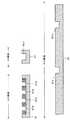
図11及び図12は第1の金属シート41の加工途中の平面図であり、図13及び図14はその断面図である。 11 and 12 are plan views during processing of the
なお、図13や図14の各断面図は、図11や図12におけるIV-IV線、V-V線、及びVI-VI線の各々に沿う断面図に相当する。 The cross-sectional views of FIGS. 13 and 14 correspond to the cross-sectional views taken along the lines IV-IV, V-V, and VI-VI in FIGS. 11 and 12.
最初に、図11及び図13に示すように、第1の金属シート41として厚さが0.1mm〜2.0mm、例えば0.25mm程度の銅シートを用意する。 First, as shown in FIGS. 11 and 13, a copper sheet having a thickness of 0.1 mm to 2.0 mm, for example, about 0.25 mm is prepared as the
そして、その第1の金属シート41の表面に第1のレジスト層51を塗布し、それを露光、現像することにより、第1の流路25と同じ平面形状の開口51aを第1のレジスト層51に形成する。 Then, by applying the first resist
その後に、開口51aを通じて第1の金属シート41を0.15mm程度の深さまでウエットエッチングすることにより、第1の流路25と同じ平面形状の第3の溝41xを第1の金属シート41に形成する。 After that, the
なお、ウエットエッチングに代えて、第1の金属シート41を切削加工することにより第3の溝41xを形成してもよい。 Instead of wet etching, the
第3の溝41xの幅は特に限定されない。この例では、第1の液管34を画定する部分における第3の溝41xの幅W1(図13参照)を6mmとする。また、第1の蒸気管33を画定する部分や、凝縮器27を通る部分の第3の溝41xの幅W2(図13参照)は7mmである。 The width of the
更に、第1の蒸発器31に相当する部分の第1の金属シート41には、上記のエッチングにより流路方向に延びる蒸気溝41dが間隔をおいて複数形成される。蒸気溝41dは、第1の蒸発器31において第1の蒸気Cv1が通る流路として機能し、その深さは0.15mmであり、幅W3(図13参照)は1mm程度である。 Further, a plurality of
また、図13に示すように、隣接する蒸気溝41dの間には、毛細管力で液相の第1の作動流体C1を保持するための複数の微細なチャネル41eが形成される。そのチャネル41eの深さは、蒸気溝41dと同様に0.15mm程度である。また、チャネル41eの幅W4と、隣接するチャネル41eの間隔pは、いずれも0.1mm程度である。Further, as shown in FIG. 13, a plurality of
このエッチングを終了後、第1のレジスト層51は除去される。 After completing this etching, the first resist
次いで、図12及び図14に示すように、第1の金属シート41の不要部分を打ち抜くことにより、第1の金属シート41に対する加工を終える。 Next, as shown in FIGS. 12 and 14, the processing of the
なお、第3の金属シート43の加工も上記した第1の金属シート41と同様のウエットエッチングや切削加工により行われるのでその詳細は省略する。 Since the processing of the
図15は、加工が終了した後の第3の金属シート43の平面図であり、図16はその断面図である。 FIG. 15 is a plan view of the
なお、図16の各断面図は、図15におけるIV-IV線、V-V線、及びVI-VI線の各々に沿う断面図に相当する。 Each cross-sectional view of FIG. 16 corresponds to a cross-sectional view taken along each of the IV-IV line, the V-V line, and the VI-VI line in FIG.
図15及び図16に示すように、第3の金属シート43は厚さが0.1mm〜2.0mm、例えば0.25mmの銅シートであって、その表面には第2の流路26と同じ平面形状の第4の溝43xが形成される。 As shown in FIGS. 15 and 16, the
第4の溝43xの幅は特に限定されないが、第2の液管37を画定する部分における第4の溝43xの幅W1(図16参照)は6mmである。そして、第2の蒸気管36を画定する部分や、凝縮器27を通る部分の第4の溝43xの幅W2(図16参照)は7mmである。 The width of the
また、第2の蒸発器35に相当する部分の第3の金属シート43には流路方向に延びる蒸気溝43dが間隔をおいて複数形成される。蒸気溝43dは、第2の蒸発器35において第2の蒸気Cv2が通る流路として機能し、その深さは0.15mmであり、幅W3(図16参照)は1mm程度である。 Further, a plurality of
そして、図16に示すように、隣接する蒸気溝43dの間には毛細管力で液相の第2の作動流体C2を保持するための複数の微細なチャネル43eが0.15mm程度の深さに形成される。なお、そのチャネル43eの幅W4と、隣接するチャネル43eの間隔pは、いずれも0.1mm程度である。 Then, as shown in FIG. 16, a plurality of
次に、第2の金属シート42の加工方法について説明する。 Next, the processing method of the
図17〜図19は、第2の金属シート42の加工途中の平面図であり、図20〜図22はその断面図である。 17 to 19 are plan views during processing of the
なお、図20〜図22の各断面図は、図17〜図19におけるIV-IV線、V-V線、及びVI-VI線の各々に沿う断面図に相当する。 Each cross-sectional view of FIGS. 20 to 22 corresponds to a cross-sectional view taken along each of the IV-IV line, the V-V line, and the VI-VI line in FIGS. 17 to 19.
まず、図17及び図20に示すように、第2の金属シート42として厚さが0.1mm〜2.0mm、例えば0.4mm程度の銅シートを用意する。 First, as shown in FIGS. 17 and 20, a copper sheet having a thickness of 0.1 mm to 2.0 mm, for example, about 0.4 mm is prepared as the
そして、その第2の金属シート42の第1の表面42aに第2のレジスト層52を塗布し、それを露光、現像することにより、第1の流路25と同じ平面形状の開口52aを第2のレジスト層52に形成する。 Then, the second resist
その後、開口52aを通じて第2の金属シート42を0.15mm程度の深さまでウエットエッチングすることにより、第2の金属シート42に第1の溝42xを形成する。 Then, the
なお、ウエットエッチングに代えて、第2の金属シート42を切削加工することにより第1の溝42xを形成してもよい。 Instead of wet etching, the
第1の溝42xは、前述のように第3の溝41x(図11参照)と協働して第1の流路25を画定するものであって、第1の溝42xの各部の幅は第3の溝41xのそれらと同じである。例えば、第1の液管34を画定する部分における第1の溝42xの幅W1(図20参照)は6mmである。そして、第1の蒸気管33を画定する部分や、凝縮器27を通る部分の第1の溝42xの幅W2(図20参照)は7mmである。 The
このエッチングの後に、第2のレジスト層52は除去される。 After this etching, the second resist
次に、図18及び図21に示すように、第2の金属シート42の第2の表面42bに第3のレジスト層53を塗布する。そして、その第3のレジスト層53を露光、現像することにより、第2の流路26と同じ平面形状の開口53aを第3のレジスト層53に形成する。 Next, as shown in FIGS. 18 and 21, the third resist
そして、開口53aを通じて第2の金属シート42を0.15mm程度の深さまでウエットエッチングすることにより、第2の金属シート42に第2の溝42yを形成する。 Then, the
なお、第2の金属シート42を切削加工することにより第2の溝42yを形成してもよい。 The
第2の溝42yは、前述のように第4の溝43x(図15参照)と協働して第2の流路26を画定するものであって、第2の溝42yの各部の幅は第4の溝43xのそれらと同じである。 The
例えば、第1の液管34を画定する部分における第2の溝42yの幅W1(図21参照)は6mmである。そして、第1の蒸気管33を画定する部分や、凝縮器27を通る部分の第2の溝42yの幅W2(図21参照)は7mmである。 For example, the width W1 (see FIG. 21) of the
このエッチングの後に、第3のレジスト層53は除去される。 After this etching, the third resist
そして、図19及び図22に示すように、第2の金属シート42の不要部分を打ち抜くことにより、第2の金属シート42に対する加工を終える。 Then, as shown in FIGS. 19 and 22, the processing of the
これ以降の工程について、図23及び図24を参照して説明する。 Subsequent steps will be described with reference to FIGS. 23 and 24.
図23及び図24は、本実施形態に係るループヒートパイプの製造途中の平面図である。 23 and 24 are plan views during the manufacturing of the loop heat pipe according to the present embodiment.
まず、図23に示すように、第2の金属シート42の第1の溝42xに第1のメッシュ部材55を収容する。第1のメッシュ部材55は金属細線の金網であって、その金属細線によって微細な孔が形成される。この例では、直径が0.05mmの銅線の金網を三層積層することにより第1のメッシュ部材55とする。なお、各々の金網には平均直径が0.1mmの微細な孔が形成される。 First, as shown in FIG. 23, the
その後に、第2の金属シート42の第1の表面42aに第1の金属シート41を貼り合わせる。 After that, the
次に、図24に示すように、第2の金属シート42の第2の溝42yに、直径が0.05mmの銅線の金網を三層積層してなる第2のメッシュ部材56を収容する。その金網に形成される孔の直径は特に限定されないが、この例ではその平均直径を0.1mmとする。 Next, as shown in FIG. 24, the
そして、この状態で第2の金属シート42の第2の表面42bに第3の金属シート43を貼り合わせる。 Then, in this state, the
図25は、本工程を終了後の断面図であって、図24のVI-VI線に沿う断面図に相当する。 FIG. 25 is a cross-sectional view after the completion of this step, and corresponds to a cross-sectional view taken along the line VI-VI of FIG. 24.
図25に示すように、ここまでの工程により第1〜第3の金属シート41〜43が積層された積層体44が得られ、その積層体44の一部に凝縮器27が形成される。 As shown in FIG. 25, a
そして、これらの金属シート41〜43を約900℃に加熱しながら各金属シート41〜43同士をプレスすることにより、拡散接合によりこれらの金属シート41〜43同士を接合する。 Then, by pressing each of the
その後に、不図示の注入口から各流路25、26を減圧した後、第1の流路25に第1の作動流体C1として水を注入すると共に、第2の流路26に第2の作動流体C2として水を注入する。 After that, after depressurizing the
以上により、厚さが0.9mm程度の薄型のループヒートパイプ24が完成する。Thus, the thickness of the
上記したループヒートパイプ24の製造方法によれば、第1〜第3の金属シート41〜43同士を接合することによりループヒートパイプ24を作成するため、薄型の電子機器20に適した扁平な流路25、26を得ることができる。According to the manufacturing method of the
また、第1の流路25に第1のメッシュ部材55を収容することにより、第1の蒸発器31に熱が加わっていない初期状態において第1の流路25の全体に液相の第1の作動流体C1が均一に染み渡る。そのため、実使用下において第1の発熱部品22が発熱したときに、ループヒートパイプ24の姿勢の如何を問わずに第1の作動流体C1を蒸発させることができ、ループヒートパイプ24による冷却を始動させることが可能となる。Further, by accommodating the
そして、これと同様の理由により、第2の流路26に第2のメッシュ部材56を収容することにより、ループヒートパイプ24の姿勢の如何を問わずにループヒートパイプ24による冷却を始動させることができる。Then, the same reason, by accommodating the
(第2実施形態)
第1実施形態では、二つの発熱部品22、23を冷却するために二つの蒸発器31、35を備えたループヒートパイプについて説明したが、蒸発器の個数はこれに限定されない。(Second Embodiment)
In the first embodiment, the loop heat pipe provided with the two
本実施形態では、三つの発熱部品に対応して三つの蒸発器を備えたループヒートパイプについて説明する。 In this embodiment, a loop heat pipe provided with three evaporators corresponding to three heat generating parts will be described.
図26は、本実施形態に係る電子機器の平面図である。 FIG. 26 is a plan view of the electronic device according to the present embodiment.
なお、図26において、第1実施形態で説明したのと同じ要素には第1実施形態におけるのと同じ符号を付し、以下ではその説明を省略する。 In FIG. 26, the same elements as described in the first embodiment are designated by the same reference numerals as those in the first embodiment, and the description thereof will be omitted below.
この電子機器60は、第1実施形態と同様にスマートフォンやタブレット端末等の小型の電子機器であって、その筐体21には第1の発熱部品22、第2の発熱部品23、及び第3の発熱部品61が収容される。 The
第3の発熱部品61は、第1及び第2の発熱部品22、23と同様にCPU等の能動素子であって、ループヒートパイプ70によって冷却される。 The third
そのループヒートパイプ70は、第1実施形態で説明した第1の流路25と第2の流路26の他に第3の流路71を有する。このうち、第1の流路25と第2の流路26については第1実施形態で説明したのでその詳細は省略する。 The
第3の流路71は、第1の流路25と第2の流路26の各々と独立しており、ループ状の平面形状を有する。また、第3の流路71の内部には、第3の作動流体C3として水が封入される。 The
そして、第3の流路71の途中には、不図示のTIMを介して第3の発熱部品61に接続された第3の蒸発器72が設けられる。 Then, in the middle of the
第3の蒸発器72は、第3の発熱部品61の熱で第3の作動流体C3を蒸発させることにより、第3の作動流体C3の第3の蒸気Cv3を生成する。その第3の蒸気Cv3は、第3の流路71に設けられた第3の蒸気管73を通って凝縮器27に至る。 The
凝縮器27は、第3の流路71に重なる矩形状の平面形状を有しており、外気との熱交換によって第3の作動流体C3を冷却して液化する。 The
そして、凝縮器27において液化した第3の作動流体C3は、第3の流路71に設けられた第3の液管74を通って再び第3の蒸発器72に戻る。 Then, the third working fluid C3 liquefied in the
そのループヒートパイプ70は、以下のように第1〜第4の金属シートを積層することにより製造され得る。 The
図27〜図29は、本実施形態に係るループヒートパイプ70の製造途中の平面図である。 27 to 29 are plan views of the
まず、図27に示すように、第1の金属シート41と第2の金属シート42の各々として銅シートを用意する。 First, as shown in FIG. 27, a copper sheet is prepared as each of the
その第1の金属シート41の表面には、第1実施形態で説明した第3の溝41xが形成される。また、第2の金属シート42の第1の表面42aには前述の第1の溝42xが形成されており、第2の表面42bには前述の第2の溝42yが形成される。 A
そして、その第1の溝42xに第1のメッシュ部材55を収容した後、第2の金属シート42の第1の表面42aに第1の金属シート41を貼り合わせる。 Then, after accommodating the
次に、図28に示すように、第2の金属シート42の第2の溝42yに第2のメッシュ部材56を収容する。 Next, as shown in FIG. 28, the
更に、その第2の金属シート42の他に、第3の金属シート43として銅シートを用意する。 Further, in addition to the
その第3の金属シート43は、第2の金属シート42に対向する第3の表面43aと、その第3の表面43aに相対する第4の表面43bとを有する。 The
このうち、第3の表面43aには前述の第4の溝43xが形成されている。一方、第4の表面43bには、第3の流路71を画定する第5の溝43yが形成されている。 Of these, the above-mentioned
そして、上記のように第2の溝42yに第2のメッシュ部材56が収容されている状態で、第2の金属シート42の第2の表面42bに第3の金属シート43の第3の表面43aを貼り合わせる。 Then, in a state where the
続いて、図29に示すように、第3の金属シート43の第5の溝43yに第3のメッシュ部材75を収容する。第3のメッシュ部材75は、第1のメッシュ部材55や第2のメッシュ部材56と同様に、直径が0.05mmの銅線の金網を三層積層することにより作製される。なお、その金網に形成される孔の直径は平均で0.1mm程度である。Subsequently, as shown in FIG. 29, the
第3のメッシュ部材75は、第3の蒸発器72に熱が加わっていない初期状態において液相の第3の作動流体C3を保持するように機能する。よって、実使用下において第3の発熱部品61が発熱することにより、ループヒートパイプ70の姿勢の如何を問わずに第3の作動流体C3が蒸発し、ループヒートパイプ70による冷却を始動することができる。 The
更に、その第3の金属シート43の他に、第4の金属シート77として厚さが0.25mm程度の銅シートを用意する。 Further, in addition to the
第4の金属シート77の表面には、第5の溝43yと協働して第3の流路71を画定する第6の溝77xが形成される。 On the surface of the
そして、上記のように第5の溝43yに第3のメッシュ部材75が収容されている状態で、第3の金属シート43の第4の表面43bに第4の金属シート77を貼り合わせる。 Then, with the
図30は、本工程を終了後の断面図であって、図29のVI-VI線に沿う断面図に相当する。 FIG. 30 is a cross-sectional view after the completion of this step, and corresponds to a cross-sectional view taken along the line VI-VI of FIG. 29.
図30に示すように、ここまでの工程により第1〜第4の金属シート41〜43、77が積層された積層体80が得られる。 As shown in FIG. 30, the
そして、これらの金属シート41〜43、77を約900℃に加熱しながら各金属シート41〜43、77同士をプレスすることにより、拡散接合によりこれらの金属シート41〜43、77同士を接合する。 Then, by pressing each of the
その後に、不図示の注入口から各流路25、26、71を減圧した後、これらの流路25、26、71の各々に第1〜第3の作動流体C1〜C3として水を注入する。 Then, after depressurizing each of the
以上により、本実施形態に係るループヒートパイプ70が完成する。 As described above, the
上記した本実施形態によれば、第1〜第3の発熱部品22、23、61の各々に対応した第1〜第3の流路25、26、71をループヒートパイプ70に設けるため、これら三つの発熱部品22、23、61を一つのループヒートパイプ70で同時に冷却できる。 According to the present embodiment described above, since the first to
以上、各実施形態について詳細に説明したが、各実施形態は上記に限定されない。例えば、第1〜第3の流路25、26、71の幅は上記に限定されず、ループヒートパイプ24、70に求められる熱輸送性能に応じて適宜最適化し得る。 Although each embodiment has been described in detail above, each embodiment is not limited to the above. For example, the widths of the first to
以上説明した各実施形態に関し、更に以下の付記を開示する。 The following additional notes will be further disclosed with respect to each of the above-described embodiments.
(付記1) 第1の金属シート、第2の金属シート、及び第3の金属シートが順に積層された積層体と、
前記第1の金属シートと前記第2の金属シートとの間に設けられ、第1の作動流体が封入されたループ状の第1の流路と、
前記第1の流路の途中に設けられ、前記第1の作動流体を蒸発させる第1の蒸発器と、
前記第2の金属シートと前記第3の金属シートとの間に設けられ、第2の作動流体が封入されたループ状の第2の流路と、
前記第2の流路の途中に設けられ、前記第2の作動流体を蒸発させる第2の蒸発器と、
前記積層体の一部に設けられ、前記第1の作動流体と前記第2の作動流体を凝縮させる凝縮器と、
を有するループヒートパイプ。(Appendix 1) A laminate in which a first metal sheet, a second metal sheet, and a third metal sheet are laminated in this order, and
A loop-shaped first flow path provided between the first metal sheet and the second metal sheet and in which the first working fluid is sealed,
A first evaporator provided in the middle of the first flow path and evaporating the first working fluid, and
A loop-shaped second flow path provided between the second metal sheet and the third metal sheet and in which a second working fluid is sealed, and
A second evaporator provided in the middle of the second flow path and evaporating the second working fluid, and
A condenser provided in a part of the laminate and condensing the first working fluid and the second working fluid,
Loop heat pipe with.
(付記2) 前記第1の流路と前記第2の流路とが平面視で交差することを特徴とする付記1に記載のループヒートパイプ。 (Supplementary note 2) The loop heat pipe according to
(付記3) 前記第2の金属シートは、前記第3の金属シートに対向する表面を有し、
前記第1の流路と前記第2の流路とが交差する部分において、前記第2の溝の底面の高さが、前記表面の高さ以下であることを特徴とする付記2に記載のループヒートパイプ。(Appendix 3) The second metal sheet has a surface facing the third metal sheet and has a surface facing the third metal sheet.
The description in
(付記4) 前記第1の流路は、前記第1の蒸発器で蒸発した前記第1の作動流体が流れる第1の蒸気管を有し、
前記第2の流路は、前記第2の蒸発器で蒸発した前記第2の作動流体が流れる第2の蒸気管を有し、
前記凝縮器において前記第1の蒸気管と前記第2の蒸気管とが平面視で交差することを特徴とする付記2に記載のループヒートパイプ。(Appendix 4) The first flow path has a first steam pipe through which the first working fluid vaporized by the first evaporator flows.
The second flow path has a second steam pipe through which the second working fluid vaporized by the second evaporator flows.
The loop heat pipe according to
(付記5) 前記第1の流路は、前記凝縮器で凝縮した前記第1の作動流体が流れる第1の液管を有し、
前記第2の流路は、前記凝縮器で凝縮した前記第2の作動流体が流れる第2の液管を有し、
前記第1の液管と前記第2の液管とが平面視で交差することを特徴とする付記2に記載のループヒートパイプ。(Appendix 5) The first flow path has a first liquid pipe through which the first working fluid condensed by the condenser flows.
The second flow path has a second liquid pipe through which the second working fluid condensed by the condenser flows.
The loop heat pipe according to
(付記6) 前記第2の金属シートは、前記第1の金属シートに対向する第1の表面と、前記第3の金属シートに対向する第2の表面とを有し、
前記第1の表面が前記第1の流路の内面を画定し、前記第2の表面が前記第2の流路の内面を画定することを特徴とする付記1に記載のループヒートパイプ。(Appendix 6) The second metal sheet has a first surface facing the first metal sheet and a second surface facing the third metal sheet.
The loop heat pipe according to
(付記7) 前記第1の表面に、前記第1の流路の一部を画定する第1の溝が形成され、
前記第2の表面に、前記第2の流路の一部を画定する第2の溝が形成されたことを特徴とする付記6に記載のループヒートパイプ。(Appendix 7) A first groove defining a part of the first flow path is formed on the first surface.
The loop heat pipe according to
(付記8) 前記第3の金属シートの上に積層された第4の金属シートと、
前記第3の金属シートと前記第4の金属シートとの間に形成されたループ状の平面形状を有し、第3の作動流体が封入された第3の流路と、
前記第3の流路の途中に設けられ、前記第3の作動流体を蒸発させる第3の蒸発器とを更に有することを特徴とする付記1に記載のループヒートパイプ。(Appendix 8) A fourth metal sheet laminated on the third metal sheet and
A third flow path having a loop-shaped planar shape formed between the third metal sheet and the fourth metal sheet and in which a third working fluid is sealed, and a third flow path.
The loop heat pipe according to
(付記9) 前記凝縮器は、平面視で前記第1の流路と前記第2の流路の各々に重なることを特徴とする付記1に記載のループヒートパイプ。 (Supplementary note 9) The loop heat pipe according to
(付記10) 第1の金属シート、第2の金属シート、及び第3の金属シートが順に積層された積層体と、
前記第1の金属シートと前記第2の金属シートとの間に設けられ、第1の作動流体が封入されたループ状の第1の流路と、
前記第1の流路の途中に設けられ、前記第1の作動流体を蒸発させる第1の蒸発器と、
前記第2の金属シートと前記第3の金属シートとの間に設けられ、第2の作動流体が封入されたループ状の第2の流路と、
前記第2の流路の途中に設けられ、前記第2の作動流体を蒸発させる第2の蒸発器と、
前記積層体の一部に設けられ、前記第1の作動流体と前記第2の作動流体を凝縮させる凝縮器と、
前記第1の蒸発器に接続された第1の発熱部品と、
前記第2の蒸発器に接続された第2の発熱部品と、
を有する電子機器。(Appendix 10) A laminate in which a first metal sheet, a second metal sheet, and a third metal sheet are laminated in this order, and
A loop-shaped first flow path provided between the first metal sheet and the second metal sheet and in which the first working fluid is sealed,
A first evaporator provided in the middle of the first flow path and evaporating the first working fluid, and
A loop-shaped second flow path provided between the second metal sheet and the third metal sheet and in which a second working fluid is sealed, and
A second evaporator provided in the middle of the second flow path and evaporating the second working fluid, and
A condenser provided in a part of the laminate and condensing the first working fluid and the second working fluid,
With the first heat generating component connected to the first evaporator,
With the second heat generating component connected to the second evaporator,
Electronic equipment with.
1…ループヒートパイプ、2…電子機器、3…蒸発器、4…凝縮器、5…蒸気管、6…液管、7…発熱部品、11…第1の銅シート、11a…第1の溝、12…第2の銅シート、12a…第2の溝、20…電子機器、21…筐体、22…第1の発熱部品、23…第2の発熱部品、24…ループヒートパイプ、25…第1の流路、26…第2の流路、27…凝縮器、31…第1の蒸発器、33…第1の蒸気管、34…第1の液管、35…第2の蒸発器、36…第2の蒸気管、37…第2の液管、41…第1の金属シート、41x…第3の溝、42…第2の金属シート、42a…第1の表面、42b…第2の表面、42x…第1の溝、42y…第2の溝、43…第3の金属シート、43a…第3の表面、43b…第4の表面、43x…第4の溝、43y…第5の溝、44…積層体、51…第1のレジスト層、51a…開口、52…第2のレジスト層、52a…開口、53…第3のレジスト層、53a…開口、55…第1のメッシュ部材、56…第2のメッシュ部材、60…電子機器、61…第3の発熱部品、70…ループヒートパイプ、71…第3の流路、72…第3の蒸発器、73…第3の蒸気管、74…第3の液管、75…第3のメッシュ部材、77…第4の金属シート、77x…第6の溝、80…積層体。1 ... Loop heat pipe, 2 ... Electronic equipment, 3 ... Evaporator, 4 ... Condenser, 5 ... Steam pipe, 6 ... Liquid pipe, 7 ... Heat generating parts, 11 ... First copper sheet, 11a ... First groove , 12 ... 2nd copper sheet, 12a ... 2nd groove, 20 ... electronic equipment, 21 ... housing, 22 ... first heat generating component, 23 ... second heat generating component, 24 ... loop heat pipe, 25 ... 1st flow path, 26 ... 2nd flow path, 27 ... Condenser, 31 ... 1st evaporator, 33 ... 1st steam pipe, 34 ... 1st liquid pipe, 35 ... 2nd evaporator , 36 ... second steam pipe, 37 ... second liquid pipe, 41 ... first metal sheet, 41x ... third groove, 42 ... second metal sheet, 42a ... first surface, 42b ... second 2 surface, 42x ... 1st groove, 42y ... 2nd groove, 43 ... 3rd metal sheet, 43a ... 3rd surface, 43b ... 4th surface, 43x ... 4th groove, 43y ... 5 grooves, 44 ... laminate, 51 ... first resist layer, 51a ... opening, 52 ... second resist layer, 52a ... opening, 53 ... third resist layer, 53a ... opening, 55 ... first Mesh member, 56 ... second mesh member, 60 ... electronic equipment, 61 ... third heat generating component, 70 ... loop heat pipe, 71 ... third flow path, 72 ... third evaporator, 73 ... third Steam pipe, 74 ... 3rd liquid pipe, 75 ... 3rd mesh member, 77 ... 4th metal sheet, 77x ...6th groove, 80 ... Laminate.
Claims (7)
Translated fromJapanese前記第1の金属シートと前記第2の金属シートとの間に設けられ、第1の作動流体が封入されたループ状の第1の流路と、
前記第1の流路の途中に設けられ、前記第1の作動流体を蒸発させる第1の蒸発器と、
前記第2の金属シートと前記第3の金属シートとの間に設けられ、第2の作動流体が封入されたループ状の第2の流路と、
前記第2の流路の途中に設けられ、前記第2の作動流体を蒸発させる第2の蒸発器と、
前記積層体の一部に設けられ、前記第1の作動流体と前記第2の作動流体を凝縮させる凝縮器と、
を有し、
前記第2の金属シートは、
前記第1の金属シートに対向する第1の表面と、
前記第3の金属シートに対向する第2の表面と、
を有し、
前記第1の表面に前記第1の流路を構成する第1の溝が形成され、
前記第2の表面に前記第2の流路を構成する第2の溝が形成されていることを特徴とするループヒートパイプ。A laminate in which a first metal sheet, a second metal sheet, and a third metal sheet are laminated in this order, and
A loop-shaped first flow path provided between the first metal sheet and the second metal sheet and in which the first working fluid is sealed,
A first evaporator provided in the middle of the first flow path and evaporating the first working fluid, and
A loop-shaped second flow path provided between the second metal sheet and the third metal sheet and in which a second working fluid is sealed, and
A second evaporator provided in the middle of the second flow path and evaporating the second working fluid, and
A condenser provided in a part of the laminate and condensing the first working fluid and the second working fluid,
Have a,
The second metal sheet is
With the first surface facing the first metal sheet,
With the second surface facing the third metal sheet,
Have,
A first groove forming the first flow path is formed on the first surface, and the first groove is formed.
A loop heat pipecharacterized in that a second groove forming the second flow path is formed on the second surface.
前記第1の流路と前記第2の流路とが交差する部分において、前記第1の溝と前記第2の溝とが交差することを特徴とする請求項1に記載のループヒートパイプ。The first flow path and the second flow path intersectin a plan view,
The loop heat pipe according to claim1, wherein the first groove and the second groove intersect at a portion where the first flow path and the second flow path intersect.
前記第2の流路は、前記第2の蒸発器で蒸発した前記第2の作動流体が流れる第2の蒸気管を有し、
前記凝縮器において前記第1の蒸気管と前記第2の蒸気管とが平面視で交差することを特徴とする請求項2に記載のループヒートパイプ。The first flow path has a first steam pipe through which the first working fluid vaporized by the first evaporator flows.
The second flow path has a second steam pipe through which the second working fluid vaporized by the second evaporator flows.
The loop heat pipe according to claim 2, wherein the first steam pipe and the second steam pipe intersect in a plan view in the condenser.
前記第2の流路は、前記凝縮器で凝縮した前記第2の作動流体が流れる第2の液管を有し、
前記第1の液管と前記第2の液管とが平面視で交差することを特徴とする請求項2に記載のループヒートパイプ。The first flow path has a first liquid pipe through which the first working fluid condensed by the condenser flows.
The second flow path has a second liquid pipe through which the second working fluid condensed by the condenser flows.
The loop heat pipe according to claim 2, wherein the first liquid pipe and the second liquid pipe intersect in a plan view.
前記積層体上であって前記第2の流路と平面視において重なる位置に、第2発熱部材が配置される第2領域が設けられ、前記第2領域において前記第2の溝には、液相の前記第2の作動流体を毛細管力で保持するための第2の複数チャネルが形成されるA second region on which the second heat generating member is arranged is provided at a position on the laminated body that overlaps with the second flow path in a plan view, and in the second region, the liquid is filled in the second groove. A second plurality of channels are formed to hold the second working fluid of the phase by capillary force.
ことを特徴とする請求項1乃至5いずれか一項に記載のループヒートパイプ。The loop heat pipe according to any one of claims 1 to 5, wherein the loop heat pipe is characterized.
前記第1の金属シートと前記第2の金属シートとの間に設けられ、第1の作動流体が封入されたループ状の第1の流路と、
前記第1の流路の途中に設けられ、前記第1の作動流体を蒸発させる第1の蒸発器と、
前記第2の金属シートと前記第3の金属シートとの間に設けられ、第2の作動流体が封入されたループ状の第2の流路と、
前記第2の流路の途中に設けられ、前記第2の作動流体を蒸発させる第2の蒸発器と、
前記積層体の一部に設けられ、前記第1の作動流体と前記第2の作動流体を凝縮させる凝縮器と、
前記第1の蒸発器に接続された第1の発熱部品と、
前記第2の蒸発器に接続された第2の発熱部品と、
を有し、
前記第2の金属シートは、
前記第1の金属シートに対向する第1の表面と、
前記第3の金属シートに対向する第2の表面と、
を有し、
前記第1の表面に前記第1の流路を構成する第1の溝が形成され、
前記第2の表面に前記第2の流路を構成する第2の溝が形成されていることを特徴とする電子機器。A laminate in which a first metal sheet, a second metal sheet, and a third metal sheet are laminated in this order, and
A loop-shaped first flow path provided between the first metal sheet and the second metal sheet and in which the first working fluid is sealed,
A first evaporator provided in the middle of the first flow path and evaporating the first working fluid, and
A loop-shaped second flow path provided between the second metal sheet and the third metal sheet and in which a second working fluid is sealed, and
A second evaporator provided in the middle of the second flow path and evaporating the second working fluid, and
A condenser provided in a part of the laminate and condensing the first working fluid and the second working fluid,
With the first heat generating component connected to the first evaporator,
With the second heat generating component connected to the second evaporator,
Have a,
The second metal sheet is
With the first surface facing the first metal sheet,
With the second surface facing the third metal sheet,
Have,
A first groove forming the first flow path is formed on the first surface, and the first groove is formed.
An electronic devicecharacterized in that a second groove forming the second flow path is formed on the second surface.
Priority Applications (1)
| Application Number | Priority Date | Filing Date | Title |
|---|---|---|---|
| JP2016217241AJP6852352B2 (en) | 2016-11-07 | 2016-11-07 | Loop heat pipes and electronics |
Applications Claiming Priority (1)
| Application Number | Priority Date | Filing Date | Title |
|---|---|---|---|
| JP2016217241AJP6852352B2 (en) | 2016-11-07 | 2016-11-07 | Loop heat pipes and electronics |
Publications (2)
| Publication Number | Publication Date |
|---|---|
| JP2018076978A JP2018076978A (en) | 2018-05-17 |
| JP6852352B2true JP6852352B2 (en) | 2021-03-31 |
Family
ID=62148980
Family Applications (1)
| Application Number | Title | Priority Date | Filing Date |
|---|---|---|---|
| JP2016217241AExpired - Fee RelatedJP6852352B2 (en) | 2016-11-07 | 2016-11-07 | Loop heat pipes and electronics |
Country Status (1)
| Country | Link |
|---|---|
| JP (1) | JP6852352B2 (en) |
Families Citing this family (3)
| Publication number | Priority date | Publication date | Assignee | Title |
|---|---|---|---|---|
| JP7161343B2 (en) | 2018-08-27 | 2022-10-26 | 新光電気工業株式会社 | Cooler |
| CN109579585B (en)* | 2019-01-10 | 2023-09-12 | 中国科学院上海技术物理研究所 | Multi-evaporator loop heat pipe |
| CN113099699A (en)* | 2021-04-13 | 2021-07-09 | 安徽赛聚新材料有限公司 | Digital heat-resistant modified plastic part of electronic and electric appliances and processing device thereof |
Family Cites Families (5)
| Publication number | Priority date | Publication date | Assignee | Title |
|---|---|---|---|---|
| US6804117B2 (en)* | 2002-08-14 | 2004-10-12 | Thermal Corp. | Thermal bus for electronics systems |
| TWI274839B (en)* | 2004-12-31 | 2007-03-01 | Foxconn Tech Co Ltd | Pulsating heat conveyance apparatus |
| JP5471119B2 (en)* | 2009-07-24 | 2014-04-16 | 富士通株式会社 | Loop heat pipe, electronic device |
| JP5765047B2 (en)* | 2011-05-02 | 2015-08-19 | 富士通株式会社 | Multi-loop heat pipe and electronic device |
| JP6233125B2 (en)* | 2014-03-20 | 2017-11-22 | 富士通株式会社 | Loop-type heat pipe, manufacturing method thereof, and electronic device |
- 2016
- 2016-11-07JPJP2016217241Apatent/JP6852352B2/ennot_activeExpired - Fee Related
Also Published As
| Publication number | Publication date |
|---|---|
| JP2018076978A (en) | 2018-05-17 |
Similar Documents
| Publication | Publication Date | Title |
|---|---|---|
| US11789505B2 (en) | Loop heat pipe | |
| US11536518B2 (en) | Fabrication method for loop heat pipe | |
| US10704838B2 (en) | Loop heat pipe | |
| JP6233125B2 (en) | Loop-type heat pipe, manufacturing method thereof, and electronic device | |
| US10420253B2 (en) | Loop heat pipe, manufacturing method thereof, and electronic device | |
| JP6648824B2 (en) | Loop heat pipe, method for manufacturing the same, and electronic equipment | |
| US20100326632A1 (en) | Phase-change-type heat spreader, flow-path structure, electronic apparatus,and method of producing a phase-change-type heat spreader | |
| US10712098B2 (en) | Loop heat pipe and method of manufacturing loop heat pipe | |
| US11060798B2 (en) | Loop heat pipe | |
| JP6951267B2 (en) | Heat pipe and its manufacturing method | |
| JP6852352B2 (en) | Loop heat pipes and electronics | |
| JP2020008249A (en) | Loop type heat pipe and method for manufacturing the same | |
| JP6999452B2 (en) | Loop type heat pipe and loop type heat pipe manufacturing method | |
| JP6991892B2 (en) | Loop type heat pipe | |
| Mantelli et al. | Experimental study of multidimensional wire-plate/sintered hybrid mini heat pipes for electronics | |
| JP7631133B2 (en) | Loop Heat Pipe | |
| US11808521B2 (en) | Loop heat pipe |
Legal Events
| Date | Code | Title | Description |
|---|---|---|---|
| RD03 | Notification of appointment of power of attorney | Free format text:JAPANESE INTERMEDIATE CODE: A7423 Effective date:20180215 | |
| RD04 | Notification of resignation of power of attorney | Free format text:JAPANESE INTERMEDIATE CODE: A7424 Effective date:20180220 | |
| A621 | Written request for application examination | Free format text:JAPANESE INTERMEDIATE CODE: A621 Effective date:20190709 | |
| A977 | Report on retrieval | Free format text:JAPANESE INTERMEDIATE CODE: A971007 Effective date:20200630 | |
| A131 | Notification of reasons for refusal | Free format text:JAPANESE INTERMEDIATE CODE: A131 Effective date:20200721 | |
| A521 | Request for written amendment filed | Free format text:JAPANESE INTERMEDIATE CODE: A523 Effective date:20200814 | |
| TRDD | Decision of grant or rejection written | ||
| A01 | Written decision to grant a patent or to grant a registration (utility model) | Free format text:JAPANESE INTERMEDIATE CODE: A01 Effective date:20210209 | |
| A61 | First payment of annual fees (during grant procedure) | Free format text:JAPANESE INTERMEDIATE CODE: A61 Effective date:20210222 | |
| R150 | Certificate of patent or registration of utility model | Ref document number:6852352 Country of ref document:JP Free format text:JAPANESE INTERMEDIATE CODE: R150 | |
| LAPS | Cancellation because of no payment of annual fees |