JP6852050B2 - Modular uniplanar pedicle screw assembly for use with multiaxial bone fasteners - Google Patents
Modular uniplanar pedicle screw assembly for use with multiaxial bone fastenersDownload PDFInfo
- Publication number
- JP6852050B2 JP6852050B2JP2018507713AJP2018507713AJP6852050B2JP 6852050 B2JP6852050 B2JP 6852050B2JP 2018507713 AJP2018507713 AJP 2018507713AJP 2018507713 AJP2018507713 AJP 2018507713AJP 6852050 B2JP6852050 B2JP 6852050B2
- Authority
- JP
- Japan
- Prior art keywords
- assembly
- plane
- tulip
- clamp
- bone
- Prior art date
- Legal status (The legal status is an assumption and is not a legal conclusion. Google has not performed a legal analysis and makes no representation as to the accuracy of the status listed.)
- Active
Links
- 210000000988bone and boneAnatomy0.000titleclaimsdescription146
- 241000722921Tulipa gesnerianaSpecies0.000claimsdescription241
- 238000003780insertionMethods0.000claimsdescription17
- 230000037431insertionEffects0.000claimsdescription17
- 230000000295complement effectEffects0.000claimsdescription6
- 230000000712assemblyEffects0.000description12
- 238000000429assemblyMethods0.000description12
- 238000001356surgical procedureMethods0.000description11
- 230000015572biosynthetic processEffects0.000description9
- 230000004927fusionEffects0.000description6
- 230000007246mechanismEffects0.000description6
- 230000000903blocking effectEffects0.000description5
- 230000005856abnormalityEffects0.000description4
- 208000032170Congenital AbnormalitiesDiseases0.000description3
- 230000008859changeEffects0.000description3
- 238000000034methodMethods0.000description3
- 206010023509KyphosisDiseases0.000description2
- 206010039722scoliosisDiseases0.000description2
- 206010061246Intervertebral disc degenerationDiseases0.000description1
- 206010028980NeoplasmDiseases0.000description1
- 206010058907Spinal deformityDiseases0.000description1
- 238000004873anchoringMethods0.000description1
- 230000006378damageEffects0.000description1
- 201000010099diseaseDiseases0.000description1
- 208000037265diseases, disorders, signs and symptomsDiseases0.000description1
- 230000006870functionEffects0.000description1
- 230000035876healingEffects0.000description1
- 230000003100immobilizing effectEffects0.000description1
- 238000011065in-situ storageMethods0.000description1
- 208000014674injuryDiseases0.000description1
- 239000002184metalSubstances0.000description1
- 210000000653nervous systemAnatomy0.000description1
- 230000008569processEffects0.000description1
- 230000001105regulatory effectEffects0.000description1
- 210000003371toeAnatomy0.000description1
- 230000008733traumaEffects0.000description1
- 239000011800void materialSubstances0.000description1
Images


Classifications
- A—HUMAN NECESSITIES
- A61—MEDICAL OR VETERINARY SCIENCE; HYGIENE
- A61B—DIAGNOSIS; SURGERY; IDENTIFICATION
- A61B17/00—Surgical instruments, devices or methods
- A61B17/56—Surgical instruments or methods for treatment of bones or joints; Devices specially adapted therefor
- A61B17/58—Surgical instruments or methods for treatment of bones or joints; Devices specially adapted therefor for osteosynthesis, e.g. bone plates, screws or setting implements
- A61B17/68—Internal fixation devices, including fasteners and spinal fixators, even if a part thereof projects from the skin
- A61B17/70—Spinal positioners or stabilisers, e.g. stabilisers comprising fluid filler in an implant
- A61B17/7001—Screws or hooks combined with longitudinal elements which do not contact vertebrae
- A61B17/7035—Screws or hooks, wherein a rod-clamping part and a bone-anchoring part can pivot relative to each other
- A61B17/7038—Screws or hooks, wherein a rod-clamping part and a bone-anchoring part can pivot relative to each other to a different extent in different directions, e.g. within one plane only
- A—HUMAN NECESSITIES
- A61—MEDICAL OR VETERINARY SCIENCE; HYGIENE
- A61B—DIAGNOSIS; SURGERY; IDENTIFICATION
- A61B17/00—Surgical instruments, devices or methods
- A61B17/56—Surgical instruments or methods for treatment of bones or joints; Devices specially adapted therefor
- A61B17/58—Surgical instruments or methods for treatment of bones or joints; Devices specially adapted therefor for osteosynthesis, e.g. bone plates, screws or setting implements
- A61B17/68—Internal fixation devices, including fasteners and spinal fixators, even if a part thereof projects from the skin
- A61B17/70—Spinal positioners or stabilisers, e.g. stabilisers comprising fluid filler in an implant
- A61B17/7001—Screws or hooks combined with longitudinal elements which do not contact vertebrae
- A61B17/7035—Screws or hooks, wherein a rod-clamping part and a bone-anchoring part can pivot relative to each other
- A61B17/7037—Screws or hooks, wherein a rod-clamping part and a bone-anchoring part can pivot relative to each other wherein pivoting is blocked when the rod is clamped
- A—HUMAN NECESSITIES
- A61—MEDICAL OR VETERINARY SCIENCE; HYGIENE
- A61B—DIAGNOSIS; SURGERY; IDENTIFICATION
- A61B17/00—Surgical instruments, devices or methods
- A61B17/56—Surgical instruments or methods for treatment of bones or joints; Devices specially adapted therefor
- A61B2017/564—Methods for bone or joint treatment
Landscapes
- Health & Medical Sciences (AREA)
- Orthopedic Medicine & Surgery (AREA)
- Life Sciences & Earth Sciences (AREA)
- Neurology (AREA)
- Surgery (AREA)
- Heart & Thoracic Surgery (AREA)
- Engineering & Computer Science (AREA)
- Biomedical Technology (AREA)
- Nuclear Medicine, Radiotherapy & Molecular Imaging (AREA)
- Medical Informatics (AREA)
- Molecular Biology (AREA)
- Animal Behavior & Ethology (AREA)
- General Health & Medical Sciences (AREA)
- Public Health (AREA)
- Veterinary Medicine (AREA)
- Surgical Instruments (AREA)
Description
Translated fromJapanese本発明は、概して、茎ねじアセンブリに関し、より具体的には、多軸骨締付具に手術中に連結され得る一平面上チューリップアセンブリに関する。 The present invention relates generally to pedicle screw assemblies, and more specifically to uniplanar tulip assemblies that can be surgically connected to a multiaxial bone clamp.
脊柱側彎症、後彎症、脊柱前彎症等の多くの種類の脊椎の異常は、疼痛を引き起こし、運動範囲を限定し、または脊柱内の神経系を損傷する可能性がある。これらの異常は、外傷、腫瘍、椎間板変性、及び疾患から生じている可能性がある。これらの異常は、脊柱の一部分を調節し、かつ脊椎の一部分を固定化することによって治療されることが多い。この治療は、1つ以上の椎骨に複数の茎ねじアセンブリ(チューリップ要素及び骨締付具を含む)を固着させて、次に、脊椎の軸の方向に略延在する細長いロッドに茎ねじアセンブリを接続することを伴う。この接続は、典型的に、椎骨に固着された各茎ねじアセンブリのチューリップ要素に細長いロッドを取り付けることにより達成される。 Many types of spinal abnormalities, such as scoliosis, kyphosis, and kyphosis, can cause pain, limit range of motion, or damage the nervous system within the spinal column. These abnormalities may result from trauma, tumors, disc degeneration, and disease. These abnormalities are often treated by regulating a portion of the spinal column and immobilizing a portion of the spine. This treatment involves fastening multiple pedicle screw assemblies (including tulip elements and bone clamps) to one or more vertebrae, and then pedicle screw assemblies to elongated rods that extend approximately in the direction of the spinal axis. Accompanied by connecting. This connection is typically achieved by attaching an elongated rod to the tulip element of each pedicle screw assembly secured to the vertebra.
外科医が脊柱の一部分を固定化するのに使用することができる、多くの種類の茎ねじアセンブリがある。かかるアセンブリには、例えば、多軸、一軸、及び一平面上茎ねじアセンブリが含まれる。これらのアセンブリの各々は、それらのチューリップ要素が、骨締付具に対して角形成され得るかどうか、かつ骨締付具のどの平面(複数可)においてであるか、によって特徴付けられる。 There are many types of pedicle screw assemblies that surgeons can use to immobilize parts of the spinal column. Such assemblies include, for example, multiaxial, uniaxial, and uniplanar pedicle screw assemblies. Each of these assemblies is characterized by whether their tulip elements can be angled with respect to the bone clamp and in which plane (s) of the bone clamp.
多軸茎ねじアセンブリは、チューリップ移動における最大の柔軟性を提供している。より具体的には、多軸アセンブリのチューリップ要素は、そのそれぞれの骨締付具の中心軸に対して任意の方向に、かつ全ての平面において自由に枢動することが可能である。この特徴は、ロッド留置において多軸アセンブリをより変動的にすることができる。 The multi-axis stalk screw assembly offers maximum flexibility in tulip movement. More specifically, the tulip elements of a multi-axis assembly can freely pivot in any direction and in all planes with respect to the central axis of their respective bone clamps. This feature allows the multi-axis assembly to be more variable in rod placement.
一軸茎ねじアセンブリは、典型的に、骨締付具及びチューリップ要素が単一片の生体適合性金属もしくはプラスチックから加工されている点で、一体構造を有する。この種の構造は、一軸茎ねじアセンブリが骨締付具の周りを枢動し得るのを防止する。この種の一体構造はまた、チューリップ要素が骨締付具から連結解除されるのを阻止する。 Uniaxial pedicle screw assemblies typically have an integral structure in that the bone fasteners and tulip elements are machined from a single piece of biocompatible metal or plastic. This type of structure prevents the uniaxial pedicle screw assembly from being able to pivot around the bone clamp. This type of integral structure also prevents the tulip element from being disconnected from the bone clamp.
他方、一平面上茎ねじアセンブリは、チューリップ要素が、骨締付具の中心軸の周りの一平面において前後に枢動することを可能にすると同時に、全ての他の平面におけるチューリップ要素の移動を防止する。この特徴は、一平面上アセンブリが変形の矯正中に特定の平面において剛性を維持することを可能にする。しかしながら、一平面上アセンブリは、一軸アセンブリと共通の特性を共有していること、すなわち、一平面上アセンブリのチューリップ要素は、骨締付具から連結解除されるのは不可能であり、剛性を提供するために、異なる骨締付具ヘッド部形状を必要とすることに留意すべきである。これは、一平面上アセンブリの骨締付具ヘッド部が、多軸アセンブリの骨締付具ヘッド部とは異なる形状を有するという事実に起因している。一平面上アセンブリに対する形状は、一方向での角形成に耐えるように設計されているが、インサイチュで時間がかかり、危険である、より複雑な組み立てプロセスも必要とする。 On the other hand, the one-plane pedicle screw assembly allows the tulip element to pivot back and forth in one plane around the central axis of the bone fastener, while at the same time allowing the tulip element to move in all other planes. To prevent. This feature allows the one-plane assembly to maintain stiffness in a particular plane during deformation correction. However, the uniplanar assembly shares common properties with the uniaxial assembly, that is, the tulip elements of the uniplanar assembly cannot be disconnected from the bone fasteners and are rigid. It should be noted that different bone clamp head portions are required to provide. This is due to the fact that the bone clamp head portion of the uniplanar assembly has a different shape than the bone clamp head portion of the multiaxial assembly. The shape for the one-plane assembly is designed to withstand unidirectional angle formation, but also requires an in situ, time consuming, dangerous, and more complex assembly process.
この知識により、脊椎の異常を矯正するために外科手術を行う外科医は、典型的に、茎ねじアセンブリのうちのどれを特定の椎骨の茎に固着させるかについて予め決定するだろう。例えば、外科医は、ロッド留置の容易さのために特定の椎体に対して多軸茎ねじアセンブリを使用することを予め決定し得る。この決定に基づいて、外科医は、その椎体へ、単一ユニットとしての多軸アセンブリ(チューリップ要素及び骨締付具を含む)を固着させるだろう。しかしながら、多軸アセンブリを椎体へ固着させた後、外科医は、罹患した椎体に変形の矯正が必要であり、かつこの目的のためには一平面上アセンブリがより好適であろうと、手術中に判断し得る。 With this knowledge, surgeons performing surgery to correct spinal abnormalities will typically predetermine which of the pedicle screw assemblies to anchor to a particular vertebral stalk. For example, the surgeon may predetermine to use a multiaxial pedicle screw assembly for a particular vertebral body for ease of rod placement. Based on this decision, the surgeon will attach a multi-axis assembly (including tulip elements and bone fasteners) as a single unit to the vertebral body. However, after anchoring the multiaxial assembly to the vertebral body, the surgeon is undergoing surgery, whether the affected vertebral body needs to be corrected for deformation, and a uniplanar assembly may be more suitable for this purpose. Can be judged.
この問題を解決するための一方法は、最初に椎体に固着された多軸アセンブリを戻して(例えば、螺合解除により)、次に、一平面上アセンブリを同じ孔内に固着させる(例えば、螺合により)ことである。しかしながら、この解決法は、複数のステップを必要とするため時間がかかり、骨締付具の繰り返しの螺合及び螺合解除に起因して、茎/椎骨の構造的一体性を損ない得る。 One way to solve this problem is to first put the multiaxial assembly attached to the vertebral body back (eg, by unthreading) and then anchor the assembly on one plane into the same hole (eg, by unscrewing). , By screwing). However, this solution is time consuming due to the need for multiple steps and can impair the structural integrity of the stalk / vertebra due to repeated screwing and unscrewing of the bone fasteners.
先行技術のこれらの欠点に起因して、外科医が手術中に、骨締付具を螺合及び螺合解除することを必要とせずに、異なる種類のチューリップアセンブリを使用することを可能にするモジュール式茎ねじアセンブリを提供する必要がある。 Due to these shortcomings of the prior art, a module that allows the surgeon to use different types of tulip assemblies during surgery without the need to screw and unscrew the bone fasteners. It is necessary to provide a formula stem screw assembly.
本発明は、先行技術の欠点のいくつかを伴わずに、多軸チューリップアセンブリとして一平面上チューリップアセンブリを同じ骨締付具ヘッド部上に連結する方法を提供している。 The present invention provides a method of connecting uniplanar tulip assemblies on the same bone fastener head as a multiaxial tulip assembly, without some of the drawbacks of the prior art.
本発明の例示的な実施形態によると、外科医が多軸チューリップアセンブリとして同じ骨締付具上に一平面上チューリップアセンブリを装着、連結すること等を可能にするモジュール式茎ねじアセンブリが提供されている。本発明の一平面上チューリップアセンブリは、長手方向スロットと、下部分及び上部分と共に配置されたアダプタとを備える。アダプタの下部分は、多軸骨締付具のヘッド部上に配置された凹部内に受容されるようにサイズ決め及び形状決めされる。上部分(下部分から延在する)は、一平面上チューリップアセンブリの長手方向スロット、具体的には、チューリップアセンブリの鞍状要素の長手方向スロットに沿って摺動するように適合される。本構成は、(i)長手方向スロットの長手方向軸に対して平行である方向に沿った第1の平面におけるチューリップアセンブリの移動を可能にし、かつ(ii)骨締付具に対する第1の平面の側方にある第2の平面におけるチューリップアセンブリの移動を防止する。このように、外科医は、手術中に、先行技術で現在行われているように椎体から骨締付具を螺合及び螺合解除する必要なく、多軸チューリップアセンブリと一平面上チューリップアセンブリとの間で選択することができる。 According to an exemplary embodiment of the invention, a modular pedicle screw assembly is provided that allows a surgeon to mount, connect, etc. a uniplanar tulip assembly on the same bone fastener as a multiaxial tulip assembly. There is. The one-plane tulip assembly of the present invention comprises a longitudinal slot and an adapter arranged with the lower and upper portions. The lower portion of the adapter is sized and shaped to be received within a recess located on the head portion of the multiaxial bone fastener. The upper portion (extending from the lower portion) is adapted to slide along the longitudinal slot of the tulip assembly on one plane, specifically the longitudinal slot of the saddle element of the tulip assembly. The configuration allows movement of the tulip assembly in a first plane along a direction parallel to the longitudinal axis of the longitudinal slot, and (ii) a first plane with respect to the bone clamp. Prevents the tulip assembly from moving in the second plane on the side of. Thus, during surgery, the surgeon does not need to screw and unscrew the bone clamp from the vertebral body during surgery, as is currently done in the prior art, with the multiaxial tulip assembly and the uniplanar tulip assembly. You can choose between.
本発明の代替的な実施形態において、全体的なアセンブリの多軸移動を一平面上移動に制約するように適合されたチューリップアセンブリが提供されている。チューリップアセンブリは、チューリップ要素と、鞍状要素と、クランプ要素とを備える。鞍状要素は、クランプ要素を剛性収容して、アセンブリがチューリップ要素のボア内に配置される、係止クランプアセンブリを形成する。クランプ要素は、チューリップアセンブリが骨締付具ヘッド部の中心軸の周りを全方向に自由に枢動することを可能にするように、骨締付具のヘッド部上に連結されるように適合される。クランプ要素が鞍状要素内で圧縮されると、チューリップアセンブリは、もはや自由に枢動することができない。すなわち、チューリップアセンブリの多軸移動は、クランプ要素が鞍状要素内で圧縮された場合であっても、一平面上移動に制約される。これは、鞍状要素が、チューリップ要素の内側表面上に配置された対応する凹部(例えば、キー孔)内にその各々が着座される、2つの突出部を有するという事実に起因している。本構成は、チューリップ要素が第1の平面において枢動もしくは角形成することを可能にすると同時に、第1の平面の側方にある第2の平面における剛性を提供する。 In an alternative embodiment of the invention there is provided a tulip assembly adapted to constrain the multiaxial movement of the entire assembly to one plane movement. The tulip assembly comprises a tulip element, a saddle-shaped element, and a clamp element. The saddle-shaped element rigidly accommodates the clamp element to form a locking clamp assembly in which the assembly is placed within the bore of the tulip element. The clamp element is adapted to be coupled over the bone clamp head to allow the tulip assembly to freely pivot in all directions around the central axis of the bone clamp head. Will be done. Once the clamp element is compressed within the saddle-shaped element, the tulip assembly can no longer be freely pivoted. That is, the multiaxial movement of the tulip assembly is constrained to one-plane movement, even when the clamp element is compressed within the saddle-shaped element. This is due to the fact that the saddle-shaped element has two protrusions, each of which is seated in a corresponding recess (eg, a keyhole) located on the inner surface of the tulip element. This configuration allows the tulip element to pivot or angle in the first plane while providing stiffness in the second plane lateral to the first plane.
本発明のさらなる代替的な実施形態において、チューリップ要素は、一対の対向して位置付けられた内方に突出するピンを有するスリーブアセンブリに連結される。スリーブアセンブリのピンは、チューリップ要素の移動の第1の平面における骨締付具の中心軸の周りを枢動する移動を防止するように適合されると同時に、第1の平面の側方にある第2の平面における剛性を提供する。 In a further alternative embodiment of the invention, the tulip element is connected to a sleeve assembly with a pair of opposed, inwardly projecting pins. The pins of the sleeve assembly are fitted to prevent pivotal movement around the central axis of the bone clamp in the first plane of movement of the tulip element, while at the same time being lateral to the first plane. It provides rigidity in the second plane.
本発明のさらなる実施形態において、チューリップ要素及び骨締付具ヘッド部は、骨締付具に対する回転及び並進能力をチューリップ要素に提供するように、並進ロッドを受容するように適合される、 In a further embodiment of the invention, the tulip element and the bone clamp head are adapted to accept the translation rod so as to provide the tulip element with rotational and translational capabilities for the bone clamp.
本発明のこれらの利点は、以下の開示及び添付の特許請求の範囲から明らかであろう。
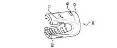
多軸骨締付具と共に使用するためのモジュール式一平面上茎ねじアセンブリ
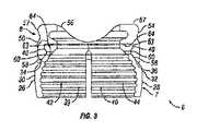
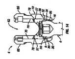
図1は、本発明の例示的な実施形態による多軸茎ねじアセンブリ2の分解図である。例示されているように、多軸茎ねじアセンブリ2は、多軸骨締付具4と、チューリップ要素10及び係止クランプアセンブリ6(例えば、クランプ要素7及び鞍状要素8を備え得る)を有する多軸チューリップアセンブリ101と、係止キャップアセンブリ12とを備え得る。下により詳細に考察されるように、骨締付具4は、係止クランプアセンブリ6が内部にすでに装填された状態で、チューリップ要素10の底部から装填され得る。所定位置に係止される前、チューリップ要素10は、骨締付具4の中心軸に対して複数の位置において枢動、角形成、及び回転され得る。いったんチューリップ要素10が骨締付具4に対する所望位置にくると、チューリップ要素10は、骨締付具4上に係止され得る。例示されている実施形態において、係止キャップアセンブリ12は、ロッド14をチューリップ要素10内に固定するように構成される。一実施形態において、チューリップ要素10は、ロッド14がチューリップ要素10内に固定された状態で、同時に骨締付具4上に固定される。Modular One-Plane Stem Thread Assembly for Use with Multiaxial Bone Tightener FIG. 1 is an exploded view of the multiaxial pedicle assembly 2 according to an exemplary embodiment of the present invention. As illustrated, the multi-axis pedicle screw assembly 2 has a multi-axis bone fastener 4 and a
図1により例示されているように、骨締付具4は、ヘッド部16と、ヘッド部16から延在するシャフト18とを含む。例示されている実施形態は、テーパ形状を有するシャフト18及びねじ山20を示す。当業者であれば、シャフト18が、例えば、特定の用途に応じて、ねじ山ピッチ、ねじ山径に対するシャフト径、全体的なシャフト形状等の多数の異なる特徴を有し得ることを理解するだろう。ヘッド部16は、任意の一般的な形状を有し得るが、ヘッド部16の少なくとも一部分は、チューリップ要素10に対する骨締付具4の回転移動もしくは角度調節を可能にするために、湾曲表面を有し得る。例えば、ヘッド部16の少なくとも一部分は、球の一部分もしくは球体の少なくとも一部分を形成するように形状決めされ得る。例示されているように、ヘッド部16は、クランプ要素7との係合を改善する粗化もしくはテクスチャ表面22を有し得る。一定の実施形態において、ヘッド部16は、例えば、ねじ駆動工具または他の装置により係合され得る工具係合表面を有し得る。工具係合表面は、骨締付具4を骨内に駆動させるように、骨締付具4に捩じりもしくは軸力を印加することを可能にし得る。例示されている実施形態において、ヘッド部16の工具係合表面は、多角形凹部24を有する。例えば、多角形凹部24は、例えば、アレンレンチ等の六角形工具を受容する、トルクス(登録商標)形状凹部もしくは六角形凹部であり得る。本発明は、同様に、他の形状を有する工具係合表面を包含することを企図している。 As illustrated by FIG. 1, the bone clamp 4 includes a
次に、図1〜3を参照すると、係止クランプアセンブリ6のクランプ要素7は、本発明の実施形態により、より詳細に記載されるだろう。例示されているように、クランプ要素7は、第1のクランプ部分26及び第2のクランプ部分28を含む。例示されている実施形態において、第1のクランプ部分26は、第2のクランプ部分28と実質的に同一であり、かつその鏡像である。第1及び第2のクランプ部分26、28は、下により詳細に考察されているように、装着されたときに、骨締付具4のヘッド部16周りにカラーを提供する。第1及び第2のクランプ部分26、28は、チューリップ要素10によりクランプ要素7上に力が印加されたときに骨締付具4を把持する。記載及び例示されている実施形態は、概して、第1及び第2のクランプ部分26、28を実質的に同一であるものとして記載しているが、部分26、28は、可変サイズであり得、互いの鏡像である必要はない。加えて、クランプ要素7は、2つのクランプ部分(すなわち、第1及び第2のクランプ部分26、28)を有するものとして例示されているが、クランプ要素7は、骨締付具4を把持するための2つ超の部分を備え得る。 Next, with reference to FIGS. 1-3, the clamp element 7 of the locking
例示されているように、第1及び第2のクランプ部分26、28の各々は、図1及び2に最良に示されているように、湾曲もしくは円形であり得る外側表面30、32を含む。第1及び第2のクランプ部分26、28の外側表面30、32は、各々、外側テーパ状表面34、36を含み得る。加えて、外側表面30、32はまた、各々、内部に形成された少なくとも1つの切り込み38を有し得る。少なくとも1つの切り込み38は、例えば、第1及び第2のクランプ部分26、28が骨締付具4のヘッド部16を収縮させ、かつそれにしっかりと係合することを可能にし得る。外側表面30、32は、本実施形態によるチューリップ要素10内の所定位置に完全に装着及び係止されたときに、図6のチューリップ要素10の内側楔状表面86に当接及び係合するべきである。図3を特に参照すると、第1及び第2のクランプ部分26、28は、各々、内側表面39、40を含む。チューリップ要素10内の所定位置に完全に装着及び係止されると、内側表面39、40は、本実施形態による骨締付具4のヘッド部16に当接及び係合するべきである。例示されている実施形態は、骨締付具4のヘッド部16との係合を改善した粗化もしくはテクスチャ特徴部42、44を有する内側表面39、40を示す。第1及び第2のクランプ部分26、28はまた、各々、図3に最良に見られるように、外側テーパ状表面34、36上に位置され得る外側リップ部46、48を含み得る。第1及び第2のクランプ部分26、28はまた、各々、図1に最良に見られるように、上表面31、33を含み得る。 As illustrated, each of the first and
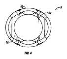
次に、図1〜5を参照すると、係止クランプアセンブリ6の鞍状要素8は、本発明の実施形態により、より詳細に記載されるだろう。例示されているように、鞍状要素8は、ボア50を含み得る。下部ボア50の下部分は、第1及び第2のクランプ部分26、28の外側リップ部46、48を含むクランプ要素7の上部分を受容するようにサイズ決めされ得る。鞍状要素8の本体は、凹状部分54を有する外側表面52を含む。外側表面52は、例えば、略円形であり得る。図4に最良に見られるように、鞍状要素8の外側表面52は、一実施形態において、略楕円形であり得る。外側表面52の楕円形状は、例えば、チューリップ要素10内に装着されたときに鞍状要素の径方向運動を限定するべきである。外側表面52の楕円形状は、例えば、チューリップ要素10内に装着されたときに鞍状要素8の径方向運動を限定するべきである。鞍状要素8は、上表面56をさらに含み得る。例示されている実施形態において、上表面56は、ロッド14を受容する座部を画定する。例示されているように、上表面56は、略凸状形状であり得る。例示されている実施形態において、鞍状要素8は、上リップ部57をさらに含む。 Next, with reference to FIGS. 1-5, the saddle-shaped element 8 of the locking
図3を特に参照すると、鞍状要素8は、内側楔状表面58をさらに含む。例示されているように、内側楔状表面58は、鞍状要素8の本体の下部分の周りに配設され得る。一実施形態において、内側楔状表面58は、円錐楔状部を形成する。内側楔状表面58は、例えば、クランプ要素7をチューリップ要素10のボア62の下に付勢するように、第1及び第2のクランプ部分26、28の外側テーパ状表面34、36に係合するように動作する。鞍状要素8は、内側楔状表面58に隣接する内側突出表面60と、内側突出表面60に隣接する内側凹状表面63とをさらに含み得る。鞍状要素8は、内側座部64をさらに含み得る。例示されているように、内側座部64は、第1及び第2のクランプ部分26、28の上表面31、33を受容するように下方に面し得る。 With particular reference to FIG. 3, the saddle-shaped element 8 further includes an inner wedge-shaped
本実施形態によると、係止クランプアセンブリ6は、チューリップ要素10内への挿入前に組み立てられ得る。一実施形態において、組み立てのために、クランプ要素7は、鞍状要素8の本体の開口を通して上方に鞍状要素8内に挿入され得る。第1及び第2のクランプ部分26、28の外側表面30、32は、クランプ要素7が挿入されたときに、鞍状要素8の内側楔状表面58に摺動係合するべきである。クランプ要素7は、第1及び第2のクランプ部分26、28の外側リップ部46、48が鞍状要素8の内側突出表面60を通過するまで挿入されるべきである。内側突出表面60は、クランプ要素7を鞍状要素8内に固定するように、外側リップ部46、48に係合する。例示されている実施形態において、係止クランプアセンブリ6は、係止クランプアセンブリが、ボア62の上部分の内径よりも大きいその最大点に外径を有するため、チューリップ要素10のボア62の上部を通して下方に嵌合しないだろう。 According to this embodiment, the locking
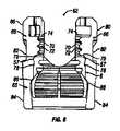
次に、図1及び6〜8を参照すると、チューリップ要素10は、本発明の実施形態により、より詳細に記載されるだろう。例示されているように、チューリップ要素10は、ボア62と、本体65と、本体65から上方に延在する一対の対向して位置付けられた側方アーム部66とを備え得る。例示されている実施形態において、アーム部66は、ロッド14を受容するようにサイズ決めされたU字形状チャネル68を画定する。アーム部66の各々は、ねじ駆動工具上の対応するねじ山に係合するためのねじ山付き部分72を有する内部表面70を有する。アーム部66の各々の内部表面70は、係止キャップアセンブリ12の対応するタブ96(例えば、図9)を受容するためのスロット74と、係止キャップアセンブリ12の対応する隆起部100(例えば、図9)に係合するための凹状表面76とをさらに含み得る。例示されているように、アーム部66の各々の凹状表面76は、スロット74上に配置され得る。アーム部66の各々の内部表面70は、図6に最良に見られるように、隆起部78をさらに含み得る。例示されている実施形態において、アーム部66の各々の隆起部78は、ねじ山付き部分72が隆起部78とスロット74との間に位置された状態で、ねじ山付き部分72の下に位置される。図6に最良に見られるように、アーム部66の各々の内部表面70は、例えば、ボア62を通した係止クランプアセンブリ6の移動を制限もしくは制約し得る、下方に面する座部79をさらに形成し得る。いくつかの実施形態において、鞍状要素8は、一対の対向して位置付けられた突起を有し、各突起は、外側表面52から側方外方に延在する。各突起は、チューリップ要素10の内部表面内に位置された対応する凹部内に受容されるように適合される。凹部は、チューリップ要素内に装着されたときに鞍状要素8の径方向運動を制限するために、突起のサイズ及び形状を補完するようにサイズ決め及び形状決めされる。続いて本発明の例示的な実施形態を参照すると、アーム部66の各々は、外側表面80をさらに含み得る。アーム部66の各々の外側表面80は、好適な工具(例示せず)によりチューリップ要素10を保持するのに使用され得る外側表面80上に形成された工具係合溝82を含み得る。 Next, referring to FIGS. 1 and 6-8, the
例示されているように、チューリップ要素10の本体65は、図1に最良に見られるように、湾曲もしくは円形であり得る外側表面84を有し得る。図6及び7を特に参照すると、本体65は、ボア62の下部分の周りに配設された内側楔状表面86をさらに含み得る。一実施形態において、内側楔状表面86は、円錐楔状部を形成する。チューリップ要素10の本体65の内側楔状表面86は、例えば、係止クランプアセンブリ6が所定位置に完全に装着及び係止されたときに、第1及び第2のクランプ部分26、28の外側表面30、32に当接及び係合し得る。 As illustrated, the
本実施形態によると、係止クランプアセンブリ6は、非係止位置もしくは係止位置のいずれかでチューリップ要素10内に装着され得る。図6は、本発明の実施形態による非係止位置でチューリップ要素10内に配設された係止クランプアセンブリ6を例示している。図6において、係止クランプアセンブリ6は、ボア62を通して上方にチューリップ要素10内に挿入されている。係止アセンブリ6は、鞍状要素8の上リップ部57がチューリップ要素10のアーム部66の内部表面70上に位置された隆起部78を通過するまで挿入されるべきである。隆起部78は、係止クランプアセンブリ6をチューリップ要素10内に固定するように上リップ部57に係合させるべきである。図6に例示されていないが、骨締付具4(例えば、図1に示される)は、次に、クランプ要素7とのスナップ嵌合を通して係止アセンブリ6内に留置され得る。クランプ要素7が骨締付具4のヘッド部16の周りに拡張及びスナップ留めするのに十分な空隙があるべきである。しかしながら、係止クランプアセンブリ6及びチューリップ要素10は、骨締付具4の中心軸に対してまだ自由に枢動及び回転するべきである。チューリップ要素10は、骨締付具4に対する所望の部分を得るように移動及び回転することができる。係止クランプアセンブリ6はまた、骨締付具4に対するチューリップ要素10の回転中に、チューリップ要素10と共に移動するべきである。いったんチューリップ要素10が所望の位置にくると、チューリップ要素10は、骨締付具4上に係止され得る。係止クランプアセンブリ6及びチューリップ要素10は、クランプアセンブリ6を骨締付具4のヘッド部16上に係止するように協働するべきである。 According to this embodiment, the locking
図7は、本発明の実施形態による係止位置でチューリップ要素10内に配設された係止クランプアセンブリ6を例示している。図7において、係止クランプアセンブリ6は、チューリップ要素10のボア62内で下方に押圧されている。例示されているように、係止クランプアセンブリ6は、鞍状要素8の上リップ部57がチューリップ要素10のアーム部66の内部表面70上に位置された隆起部78を通過するまで下方に押圧されている。係止クランプアセンブリ6が下方に移動すると、クランプ要素7は、チューリップ要素10の本体65に係合する。例示されているように、クランプ要素7の第1及び第2のクランプ部分26、28の外側表面30、32は、チューリップ要素10の本体65の内側楔状表面86に当接及び係合して、第1及び第2のクランプ部分26、28の内側表面38、40が骨締付具4(例えば、図1)のヘッド部16に係合するように付勢するべきである。係止位置において、チューリップ要素10は、骨締付具4上に係止され、よって、骨締付具4に対するチューリップ要素10のさらなる位置決めを防止するべきである。 FIG. 7 illustrates a locking
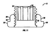
次に、図1及び9〜11を参照すると、係止キャップアセンブリ12は、本発明の実施形態により、より詳細に記載されるだろう。例示されているように、係止キャップアセンブリ12は、本体88と、本体88内のボア92内にねじ込まれたセットねじ90とを備え得る。セットねじ90は、例えば、ボア92の長さよりも長い長さを有し得る。例示されている実施形態において、セットねじ90の少なくとも一部分は、本体88の上部から延在する。一定の実施形態において、セットねじ90は、例えば、ねじ駆動工具もしくは他の装置により係合され得る工具係合表面を有し得る。工具係合表面は、医師が、本体88を通してロッド14上にセットねじ90を前進させるように、セットねじ90に捩じりもしくは軸力を印加することを可能にすることができる。係止キャップアセンブリ12がその係止位置にあるときに、セットねじ90は、ロッド14に係合するように本体88を通して前進され、ロッド14上に下方の力を印加し、それをチューリップ要素12に固定することができる。一実施形態において、セットねじ90は、ロッド14を下方に係止クランプアセンブリ6と接触するように付勢し、係止キャップアセンブリ6をチューリップ要素10内で下方に移動させる。例示されている実施形態において、セットねじ90の工具係合表面は、多角形凹部94である。例えば、多角形凹部94は、例えば、アレンチレンチ等の六角形工具を受容する六角形凹部であり得る。本発明は、例えば、他の種類のねじ回しと共に使用され得るスロットまたはクロス等の他の形状を有する工具係合表面を包含することを企図している。代替的な実施形態(例示せず)において、係合表面は、対応する凹部を有する工具もしくは装置と係合し得る突出係合表面と共に構成され得る。 Next, with reference to FIGS. 1 and 9-11, the locking
本実施形態によると、本体88は、1つ以上の突起を有し得る。例えば、本体88は、本体88の下端部から径方向に突出する下タブ96を備え得る。例示されている実施形態において、本体88は、本体88の対向側上に位置された一対の下タブ96を備え得る。例示されているように、下タブ96は、各々、略円形形状である外側表面98を有し得る。加えて、本体88は、2つの下タブ96を有するものとして例示されているが、本体88は、2つ超の下タブ96を備え得る。例示されているように、本体88は、隆起部100をさらに備え得る。隆起部100は、チューリップ要素10のアーム部66の対応する凹状表面76と係合し得る。隆起部100は、係止キャップアセンブリ12がその係止位置に達したときに、感じられるか、または聞こえ得るクリック等の触覚もしくは聴覚信号を医師に提供することができ得る。隆起部100はまた、係止キャップアセンブリ12をその係止位置に維持する助けとなり得る。例示されている実施形態において、本体88は、工具係合特徴部をさらに備え得る。工具係合特徴部は、例えば、好適な工具(例示せず)により係止キャップアセンブリ12を保持もしくは操作するのに使用され得る。例示されている実施形態において、係止キャップアセンブリ12は、上タブ102を含む。例示されているように、タブ102は、本体88の上表面に形成され得る。例示されている実施形態において、係止キャップアセンブリ12は、上表面の角部に4つの上タブ102を含む。加えて、本体88は、4つの上タブ102を有するものとして例示されているが、本体88は、およそ4つの上タブ102を備え得る。 According to this embodiment, the
係止キャップアセンブリ12をチューリップ要素10上に留置するために、下タブ96は、チューリップ要素10のアーム部66により形成されたU字形状チャネル68と整列するべきであり、係止キャップアセンブリ12は、次に、チューリップ要素10内のボア62内の下方に降下され得る。いったん下タブ96が、チューリップ要素10のアーム部66内の対応するスロット74と整列すると、係止キャップアセンブリ12は、回転することができる。スロット74は、下タブ96及びスロット74が整列したときに、下タブ96がアーム部66を通過することを可能にする。スロット74の長さは、係止キャップアセンブリ12を係止位置内に、または外に移動させるのに必要とされる回転量に略対応する。一実施形態において、係止キャップアセンブリ12は、係止位置内に留置するように、約60°〜約120°、代替的に、約80°〜約100°、代替的に、約90°回転する。先に述べられているように、隆起部100は、係止キャップアセンブリ12がその係止アセンブリに達したときに、触覚もしくは聴覚信号を医師に提供するように構成され得る。加えて、隆起部100はまた、係止キャップアセンブリ12をその係止位置に維持する助けとなり得る。アンダーカット及び幾何学的噛み合い表面等の他の特徴部を使用して、対向方向での回転を防止し得る。係止キャップアセンブリ12が所定位置に係止された状態で、セットねじ94は、次に、回転することができる。セットねじ94が下方に移動し、係止キャップアセンブリ12の基部88の底部から延在すると、セットねじ94は、ロッド14に対して押圧して、チューリップ要素10内にそれを固定する。加えて、ロッド14はまた、係止クランプアセンブリ6と係合するように下方に加圧され、チューリップ要素10内で下方にそれを付勢し得る。係止クランプアセンブリ6が下方に移動すると、クランプ要素7は、チューリップ要素10の本体65に係合する。図7に最良に見られるように、クランプ要素7の第1及び第2のクランプ部分26、28の外側表面30、32は、チューリップ要素10の本体65の内側楔状表面86に当接及び係合し、第1及び第2のクランプ部分26、28の内側表面38、40が骨締付具4のヘッド部16に係合し、チューリップ要素10に対してそれを固定するように付勢するべきである。 In order to place the locking
次に、図12〜14を参照すると、チューリップ要素10の骨締付具4上への係止が、本発明の実施形態により、より詳細に例示されている。この例示の目的上、係止キャップ要素12は示されていない。図12〜14に示されているチューリップ要素10は、チューリップ要素10が、チューリップ要素10のアーム部66の内部表面70内にねじ山付き部分72(例えば、図6〜7)もしくは下方に面する座部79(例えば、図6)を含まないことを除いて、先に記載されているチューリップ要素10と同様である。図12は、非係止位置でチューリップ要素10内に装着された係止クランプアセンブリ6を例示している。先に述べられているように、係止クランプアセンブリ6は、ボア62を通して上方にチューリップ要素10内に挿入され得る。図12に示されているように、係止アセンブリ6は、鞍状要素8の上リップ部57がチューリップ要素10の内部表面70上に位置された隆起部78を通過するまで挿入されるべきである。隆起部78は、係止クランプアセンブリ6をチューリップ要素10内に固定するように、上リップ部57に係合するべきである。図13により例示されているように、骨締付具4は、次に、クランプ要素7とのスナップ嵌合を通して係止アセンブリ6内に留置され得る。クランプ要素7が骨締付具4のヘッド部16の周りに拡張及びスナップ留めするのに十分な空隙があるべきである。しかしながら、係止クランプアセンブリ6及びチューリップ要素10は、骨締付具4に対してまだ自由に枢動及び回転するべきである。チューリップ要素10は、骨締付具4に対する所望の部分を得るように、枢動及び回転することができる。いったんチューリップ要素10が所望位置にくると、チューリップ要素10は、骨締付具4上に係止され得る。係止クランプアセンブリ6及びチューリップ要素10は、クランプアセンブリ6を骨締付具4のヘッド部16上に係止するように協働するべきである。 Next, with reference to FIGS. 12-14, the locking of the
図14は、本発明の実施形態によるチューリップ要素10に対して骨締付具4を固定するように、係止位置でチューリップ要素10内に配設され、かつ骨締付具4のヘッド部16上にクランプ留めする係止クランプアセンブリ6を例示している。図14に見られるように、係止クランプアセンブリ6は、鞍状要素8の上リップ部57がチューリップ要素10のアーム部66の内部表面70上に位置された隆起部78を通過するまで、チューリップ要素10のボア62内で下方に押圧されている。係止クランプアセンブリ6が下方に移動すると、クランプ要素7は、クランプ要素7の第1及び第2のクランプ部分26、28の外側表面30、32がチューリップ要素10の本体65の内側楔状表面86に当接及び係合して、第1及び第2のクランプ部分26、28の内側表面38、40が骨締付具4のヘッド部16に係合するように付勢するべきであるように、チューリップ要素10の本体65に係合する。係止位置において、チューリップ要素10は、骨締付具4上に係止され、よって、骨締付具4に対するチューリップ要素10のさらなる位置決めを防止するべきである。 FIG. 14 is arranged in the
外科手術手技中に、多軸チューリップアセンブリ101は、図12に示されているように、骨締付具4の多軸ヘッド部16に連結される。駆動工具により、外科医は、骨締付具4を(チューリップアセンブリ101がヘッド部16に連結された状態で)脊柱の特定の領域に位置された茎もしくは椎体内に挿入することができる。しかしながら、本開示の始めに考察されているように、外科医は、骨締付具4が茎もしくは椎体内に挿入された後、脊柱のこの特定の領域で変形の矯正が必要とされるかを手術中に判定し得る。 During the surgical procedure, the
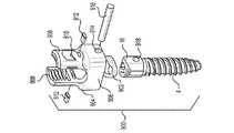
例示的な実施形態によると、外科医は、多軸チューリップアセンブリ101を骨締付具ヘッド部16から連結解除、着脱等することができ、次に、一平面上チューリップアセンブリ551を同じ骨締付具ヘッド部16上に連結、装着等することができる。下の説明から理解されるように、アダプタ502は、一平面上チューリップアセンブリ551と併せて使用されるとき、多軸骨締付具ヘッド部16に対する単一平面においてそれが枢動もしくは角形成することを可能にすると同時に、骨締付具ヘッド部16の全ての他の方向及び平面におけるチューリップアセンブリ551の移動を防止する。本発明のこれらの特徴は、図15〜18Dに関して下により詳細に記載されるだろう。 According to an exemplary embodiment, the surgeon can detach, detach, etc. the
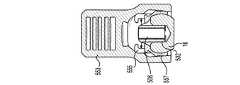
図15は、チューリップ要素553及び係止クランプアセンブリ559(すなわち、クランプ要素557及び鞍状要素555)を含む一平面上チューリップアセンブリ551を描写している。チューリップ要素553及び係止クランプアセンブリ559は、図1〜14に関して上で考察されている多軸チューリップアセンブリ101及び係止クランプアセンブリ6として同じもしくは同様の形態で共に連結もしくは組み立てられることが、本開示を読んだ後、当業者に明らかであろう。しかしながら、1つの違いは、一平面上鞍状要素555が、長手方向スロット561と、一対の対向して位置付けられた側方突出部550とを有し、それらの各々が多軸鞍状要素8内に存在しないことである。一平面上鞍状要素555の側方突出部550の各々は、チューリップ要素553の内側表面上に配置された対応する凹部563内に受容されるようにサイズ決め及び形状決めされる。いったん受容されると、鞍状要素555は、チューリップ要素553内で回転することを防止される。一平面上チューリップアセンブリ551は、図1〜14に関して上で考察されている多軸チューリップアセンブリ101と同じもしくは同様の形態で骨締付具ヘッド部16上に連結、装着等されるように適合されることにも留意するべきである。 FIG. 15 depicts a one-
図15は、各アダプタが異なる形状の下部分504を有する状態の2つのアダプタ502をさらに描写している。チューリップアセンブリ551とアダプタ502との組み合わせが、本発明によるモジュール式一平面上茎ねじアセンブリ575を形成する。図に示されているように、アダプタ502は、単一の一体構造として形成された下部分504及び上部分506を有する。代替的な実施形態において、下及び上部分は、アダプタ502を形成するように共に連結された2つの別個の部分であり得る。例示的な実施形態によると、アダプタ502の下部分504は、多軸骨締付具ヘッド部16の凹部24内に受容されるようにサイズ決め及び形状決めされる。一実施形態において、下部分504は、アダプタ502が骨締付具ヘッド部16の中心軸の周りを回転する可能性があるのを防止するために、凹部24の形状を補完する形状を有する。下部分及び凹部のこうした補完的形状は、図16に示されている。下部分504及び凹部24は、その形状が、下部分504が凹部24内で回転する可能性があるのを防止することができる限り、任意の形状(例えば、トルクス(登録商標)形状、六角形状、多角形状等)を有することができる。下により詳細に記載されるように、この物理的関係を上部分506及び長手方向スロット561の物理的関係と組み合わせることで、一平面上チューリップアセンブリ551が単一平面において枢動することを可能にすると同時に、骨締付具4の全ての他の方向及び平面におけるチューリップアセンブリ551の移動を防止することができるだろう。 FIG. 15 further illustrates two
図15に戻ると、本図は、下部分504から延在するアダプタ502の上部分506をさらに例示している。上部分506は、凹部もしくは孔510を有する上表面508、一対の対向して位置付けられた側方表面512、及び一対の対向して位置付けられた傾斜表面514により画定される。図15は、単に、1つの側方表面及び1つの傾斜表面を描写しているが、アダプタ502の1つの半体(等しい半体へと分割されたとき)は、アダプタ502の他の半体と実質的に同一であり、かつその鏡像であることに留意するべきである。続いて図15を参照すると、対向して位置付けられた傾斜表面514の各々は、フランジ516を形成し、各フランジは、多軸骨締付具ヘッド部16の上部に位置する下側を有することが示されている。 Returning to FIG. 15, this figure further illustrates the
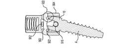
一平面上チューリップアセンブリ551が多軸骨締付具ヘッド部16の周りで枢動もしくは角形成することを可能にするために、上部分506は、鞍状要素555の長手方向スロット561内に受容されるように適合される。図17Aに示されているように、上部分506の幅は、鞍状要素555の長手方向スロット561の幅よりもわずかに小さい。すなわち、上部分506は、アダプタの側方表面512の各々が、長手方向スロット561のそれぞれの対向して位置付けられた内側壁518に対して当接するように、サイズ決め及び形状決めされる。これは、一平面上チューリップアセンブリ551が長手方向スロット561に対して垂直である方向及び平面において枢動もしくは角形成することを防止する。図17Aにさらに示されているように、上部分506は、いったん長手方向スロット561内に挿入されると、長手方向スロット561の一対の対向して位置付けられた内側壁518の上表面を越えて延在しない。しかしながら、代替的な実施形態において、上部分506は、一対の対向して位置付けられた内側壁518の上表面を越えて延在し得る。図15は、単に、1つの内側壁518を描写しているが、鞍状要素555の1つの半体(等しい半体へと分割されたとき)は、鞍状要素の他の半体と実質的に同一であり、かつその鏡像であることが、当業者により理解されるだろう。 The
上で考察されている要素の物理的関係から、上部分506は、長手方向スロット561の長手方向軸に対して平行である方向に沿った第1の平面におけるチューリップアセンブリ551(チューリップ要素553、クランプ要素557、及び鞍状要素555を含む)の移動を可能にするように、一平面上チューリップアセンブリ551の長手方向スロット561に沿って(すなわち、鞍状要素555の長手方向スロットに沿って、かつ図17B及び17Cに例示されている矢印の方向に)摺動するように適合される。長手方向スロットに沿って摺動するとき、一対の対向して位置付けられた傾斜表面514は、上部分506が長手方向スロット561に沿った所定の位置を越えて摺動することを阻止するように、チューリップアセンブリ551のそれぞれの対向して位置付けられた内側壁520(例えば、クランプ要素557、鞍状要素555、もしくはそれらの組み合わせの内側壁)に対して当接する。下及び上部分の物理的関係はまた、骨締付具4に対する第1の平面に対して側方にある第2の平面における一平面上チューリップアセンブリ551の任意の種類の枢動もしくは角形成移動を防止し、よって外科医が脊柱側彎症もしくは他の脊椎変形を罹患している患者の脊柱の特定の領域を調節する(例えば、真っ直ぐにする、変形を治す等)ことができるように、第2の平面における剛性を提供する。 Due to the physical relationship of the elements discussed above, the
例示的な実施形態によると、第1の平面における長手方向スロット561の長手方向軸に対して平行である方向は、身体の頭部から尾部への方向(すなわち、頭から足先への方向)であり、第1の平面に対して側方にある第2の平面は、身体の中央から側方への方向(すなわち、身体の中線から側部への方向)である。 According to an exemplary embodiment, the direction parallel to the longitudinal axis of the
上で考察されているように、本発明の代替的な実施形態は、一平面上チューリップアセンブリ551が枢動もしくは角形成し得る平面を変更するように、アダプタ502が多軸骨締付具ヘッド部16の中心軸の周りで回転することを可能にする。これを達成するために、下部分504は、上で考察されているように、凹部24にある間に下部分504が回転することを防止する形状ではなく、円筒形状を有する。下部分504の円筒形状は、図15に示されている。円筒状下部分504が上部分506と組み合わせて使用されるとき、この組み合わせは、一平面上チューリップアセンブリ551が(骨締付具ヘッド部16上にクランプ留めされたときであっても)ヘッド部16の中心軸の周りで回転することを可能にする。このように、外科医は、チューリップアセンブリ551が枢動もしくは角形成する平面を手術中に変更することができる。 As discussed above, in an alternative embodiment of the invention, the
例えば、アダプタ502を含む一平面上チューリップアセンブリ551は、多軸骨締付具ヘッド部16上にクランプ留めされる。外科医は、チューリップアセンブリ551の枢動もしくは角形成平面を身体の頭部から尾部への区分から中央から側方への区分へと手術中に変更したいと思うだろう。外科医は、チューリップアセンブリを90°回転させることによりこれを達成することができ、チューリップアセンブリ551は、骨締付具ヘッド部16上にクランプ留めされる。アダプタ502の上部分512は、上で考察されている方法でチューリップアセンブリ551内に配置されるため、チューリップアセンブリの90°の回転がまた、アダプタを90°回転させるだろう。いったん回転すると、一平面上チューリップアセンブリ551は、次に、中央から側方への方向に多軸骨締付具ヘッド部16の中心軸の周りで枢動もしくは角形成することができると同時に、頭部から尾部への方向の移動を防ぐことができる。 For example, the one-
チューリップアセンブリ551(円筒状下部分504を有するアダプタ502を用いるとき)が、チューリップアセンブリ551が枢動し、かつ移動を防止し得る方向/平面を変更する任意の数の角度で回転することができることは、本開示を読んだ後、当業者に明らかであるべきである。本発明の代替的な実施形態において、長手方向スロット561は、例示的な実施形態で、もしくは別の角度で示されている配向に対して垂直に配向され得る。この代替的な配向は、一平面上チューリップアセンブリ551が、例えば、制限されないが、中央から側方への方向に傾斜すると同時に、本体の頭部から尾部への方向における剛性を維持することを可能にする。 The tulip assembly 551 (when using an
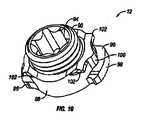
本発明はまた、ばね荷重された自己保持先端部602を備える挿入工具600を提供している。図18A〜18Dは、それぞれ、(i)アダプタ502の装填、(ii)アダプタ502の多軸骨締付具ヘッド部16の凹部24内への挿入、(iii)アダプタ502の解放、及び一平面上チューリップアセンブリ551の骨締付具ヘッド部16上への連結、ならびに(iv)挿入ステップ中のアダプタ502の不整列を例示している。 The present invention also provides an
これらの図に示されているように、自己保持先端部は、アダプタ502の孔510内に挿入されるようにサイズ決め及び形状決めされる。外科医が自己保持先端部602を孔510の上孔530内に挿入すると、自己保持先端部は、図18Aに示されているように、挿入工具600のハウジング内に上方に引き込むだろう。自己保持先端部602がハウジング内へと過度に引き込むことを防止するために、ノブ608が提供される。ノブは、内側ピン604が戻りチャネル606を横断することを制約するように適合される。いったんアダプタ502が一平面上チューリップアセンブリ551と共に挿入工具600内に装填されると、外科医は、ノブ608を挿入工具600から取り外すことができる。 As shown in these figures, the self-holding tip is sized and shaped to be inserted into the
いったんノブ608が挿入工具600から取り外されると、外科医は、図18Bに示されているように、アダプタ502の下部分504を多軸骨締付具ヘッド部16の凹部24と整列させる。ピン604は、アダプタの下部分504が凹部24の底部(整列された)もしくは骨締付具ヘッド部16の外側表面(不整列の)に対して当接するとき、戻りチャネル606を横断するだろう。ピン604が戻りチャネル606を横断すると、図18Cに示されているように、遮断機構610を左から右に同時移動させる。この段階中に、外科医は、一平面上チューリップアセンブリ551からの音声もしくは物理的フィードバックについて聞いているだろう。これらの指摘は、アダプタ502の下部分504が、凹部24内に適切に整列及び着座されていることを表している。より具体的には、音声もしくは物理的フィードバックは、チューリップアセンブリ551が、次に、骨締付具ヘッド部16内に着座され、かつ遮断機構610が、チューリップアセンブリ551が(係止クランプアセンブリ559を介して)多軸骨締付具ヘッド部16上にクランプ留めされ得るように、その点で外科医がハンドルを挿入工具600上に係合させることができる、挿入工具600(図18Cに示されているように)内の所定の位置に達したことを指摘している。しかしながら、アダプタ502の下部分504が凹部24と不整列である場合、ピン604は、戻りチャネル606に沿って過度に遠くに横断し、それにより遮断機構610は、ハンドルが外科医(図18Dに示されているように)により動作される可能性を遮断し続ける。 Once the
代替的な実施形態において、外科医は、アダプタ502の下部分504を多軸骨締付具ヘッド部16の凹部24内に単に挿入することができる。この代替的な実施形態において、挿入工具600の自己保持先端部602は、上孔530内に挿入され、アダプタ502の下部分504は、凹部24内に着座される。先端部602が上孔530と整列し、かつ上孔内への挿入に成功したとき、遮断機構610は、図18Cに示されているように、挿入工具600内の特定の位置に移動するだろう。アダプタ502の上部分506はまた、先端部602の上孔530内への挿入に成功したとき、長手方向スロット561内に挿入されることに留意するべきである。この点で、外科医は、上で考察されているように、チューリップアセンブリ551を骨締付具ヘッド部16上にクランプ留めするように、ハンドルを挿入工具600上に係合させることができる。先端部602が上孔530と不整列である場合、ピン604は、戻りチャネル606に沿って過度に遠くに横断し、それにより遮断機構610は、外科医(図18Dに示されているように)により動作される可能性を遮断し続けるだろう。 In an alternative embodiment, the surgeon can simply insert the
次に、椎骨内に挿入された多軸骨締付具4上でモジュール式一平面上茎ねじアセンブリ575を使用する方法が記載されるだろう。骨締付具4は、多軸チューリップアセンブリ101がそこに連結された状態で、椎骨内に挿入される。外科手術中のある点で、外科医は、罹患した椎体に変形の矯正が必要とされ、かつ一平面上アセンブリがこの目的のためにより好適であることを手術中に判定し得る。本発明の例示的な実施形態によると、外科医は、多軸チューリップアセンブリ101を多軸骨締付具4から連結解除するための専門工具、具体的には、骨締付具ヘッド部16を使用することができる。いったん多軸チューリップアセンブリ101が連結解除されると、外科医は、アダプタ502の下部分504を多軸骨締付具4のヘッド部16上に配置された凹部24内に挿入し得る。同様に、アダプタ502の上部分506は、図18A〜18Cに関して上で考察されているように、一平面上チューリップアセンブリ551の長手方向スロット561内に挿入される。上部分506は、長手方向スロットの長手方向軸に対して平行である方向に沿った第1の平面における一平面上チューリップアセンブリ551の移動を可能にすると同時に、骨締付具4に対して第1の平面の側方にある第2の平面における一平面上チューリップアセンブリ551の移動を防止するように長手方向スロット561に沿って摺動するように適合される。いったんアダプタの上及び下部分が挿入され、かつ一平面上チューリップアセンブリ551が骨締付具ヘッド部16上に連結されると、外科医は、融合バーを一平面上チューリップアセンブリに取り付ける。より具体的には、外科医は、融合バー14を鞍状要素555のU字形状チャネル68上に着座させ得る。例えば、係止キャップ12は、骨締付具ヘッド部16上にそれを係止させるように、一平面上チューリップアセンブリ575上にねじ込まれる。その後、外科医は、挿入されたアダプタ502及び取り付けられた融合バー14を有する一平面上チューリップアセンブリ575を使用して第2の平面における所望の位置に罹患した椎骨を移動させ得る。
枢動する鞍状要素を有するモジュール式一平面上チューリップアセンブリ
図19Aは、本発明の代替的な実施形態による一平面上チューリップアセンブリ700の斜視図である。図19B及び19Cは、それぞれ、チューリップアセンブリ700の側面及び正面断面図を示している。図20は、チューリップアセンブリ700を形成する要素を描写している。Next, a method of using the modular uniplanar
Modular one-plane tulip assembly with pivoting saddle-like elements FIG. 19A is a perspective view of a one-
図19A〜19Cは、チューリップ要素702及び係止クランプアセンブリ704(図20に描写されたクランプ要素706及び鞍状要素708を備える)を有する一平面上チューリップアセンブリ700を示している。係止クランプアセンブリ704は、図1〜14に関して上で考察されている係止クランプアセンブリ6と同じもしくは同様の形態でチューリップ要素702内に組み立て及び装着され得る。図19A〜19Cには示されていないが、多軸茎ねじアセンブリ700はまた、骨締付具と、係止キャップアセンブリとを備え、その各々は、上で考察されている骨締付具4及び係止キャップアセンブリ12と同じもしくは異なる可能性がある。 19A-19C show a one-
概して、チューリップアセンブリ700は、鞍状要素708がアダプタ502を受容するための長手方向スロット561を有し得ないことを除いて、図1に描写されているチューリップアセンブリ101と同様である。代わりに、多軸骨締付具4を有する一平面上チューリップアセンブリ700を使用することを可能にするために、チューリップ要素702の各対向して位置付けられた側方アーム部712の内側表面710は、鞍状要素708の対応する突出部716を受容するように適合された凹部714(例えば、キー孔等)と共に配置される。 In general, the
より具体的には、図19Bは、係止クランプアセンブリ704を形成するように組み立てられたクランプ要素706及び鞍状要素708を描写している。クランプ要素706は、クランプ要素を第1のクランプ部分726及び第2のクランプ部分728へと分割する少なくとも1つの切り込み738を含む。少なくとも1つの切り込み738は、例えば、第1及び第2のクランプ部分726、728が骨締付具4のヘッド部16を収縮させ、かつそれにしっかりと係合することを可能にし得る。しかしながら、図19Bは、非係止位置における(例えば、図6に関して上で考察されているように)チューリップ要素702を描写している。非係止位置において、チューリップ要素702、クランプ要素706、及び鞍状要素708は、単一ユニットとして、骨締付具4の中心軸(すなわち、図19Cの回転軸746)の周りで回転し、かつ骨締付具ヘッド部16の周りで自由に枢動/角形成することが可能である。 More specifically, FIG. 19B depicts a
ある時点で、外科医は、第1及び第2のクランプ部分726、728に骨締付具4のヘッド部16を収縮させ、かつそれに係合させ得、それによりクランプ要素706及び鞍状要素708を係止位置に(例えば、図7に関して上で考察されているように)留置し得る。係止位置において、チューリップ要素702、クランプ要素706、及び鞍状要素708は、骨締付具4の中心軸の周りでもはや回転し得ない。係止位置は、クランプ要素706及び鞍状要素708が骨締付具ヘッド部16の任意及び全ての平面において枢動/角形成することをさらに阻止する。係止位置において枢動/角形成することを可能にする唯一の要素は、チューリップ要素702であり、その要素は、多軸骨締付具ヘッド部16の単一平面において枢動/角形成することのみを可能にする。すなわち、鞍状要素708の対向して位置付けられた側方突出部716の各々は、チューリップ要素702の内側表面710上に配置されたそれぞれの凹部714内に受容されるようにサイズ決め及び形状決めされるため、チューリップ要素702は、図19Cに描写されている関節運動平面744に沿って枢動/角形成することを可能にする。関節運動平面は、例えば、限定されないが、身体の中央から側方への方向もしくは頭部から尾部への方向であり得る。外科医が、チューリップ要素702の枢動/角形成平面を再調節することを望むとき、外科医は、工具を使用してチューリップアセンブリを非係止位置に留置し、かつ上のステップを繰り返し得る。 At some point, the surgeon may contract and engage the
この構成を用いることにより、外科医は、特定の平面における剛性を提供するように、茎ねじの多軸角形成の柔軟性、及び一平面上もしくは二平面上の角形成へとねじを独立して係止させる能力を有することができる。
多軸茎ねじを一平面上茎ねじに変換するためのチューリップスリーブ
図21は、本発明の代替的な実施形態によるスリーブアセンブリ800を使用して一平面上茎ねじに変換され得る多軸茎ねじの斜視図である。By using this configuration, the surgeon can independently turn the screw into one-plane or two-plane angle formation, as well as the flexibility of multi-axis angle formation of the stalk screw to provide stiffness in a particular plane. It can have the ability to lock.
Tulip Sleeve for Converting a Multi-Stem Thread to a Uni-Stem Thread Figure 21 shows a multi-stem screw that can be converted to a uni-plane stalk screw using the
本発明のこの代替的な実施形態において、チューリップ要素10、702は、チューリップアセンブリが骨締付具ヘッド部16の特定の平面において枢動もしくは角形成することを防止するためのスリーブアセンブリ800を受容するように改変され得る。図22に示されているように、チューリップ要素802(上で考察されているチューリップ要素10、702と実質的に同じもしくは異なる構造的、物理的、かつ/または機能的特徴を有し得る)は、側方アーム部808の外側表面806の下部分に配置された凹部804を備える。他の側方アーム部810は、側方アーム部808と実質的に同一であり、かつその鏡像であることが、本開示を読んだ後、当業者に明らかであろう。各側方アーム部808、810の凹部804は、スリーブアセンブリ800をチューリップ要素802に取り付けるための対応する挿入具816を受容及び保管するようにサイズ決め及び形状決めされる。挿入具816は、スリーブアセンブリ800がチューリップ要素802に対する軸及び回転移動を防止する機能を提供するように、凹部804内に正面から嵌合する。 In this alternative embodiment of the invention, the
図23に示されているように、スリーブアセンブリ800は、第1の部分812及び第2の部分814と共に構築及び配置される。部分は、図に描写されているスリーブアセンブリ800を形成するように共に接合される。第1及び第2の部分812、814の各々は、ピン818を含む。スリーブアセンブリ800が挿入具816を介してチューリップ要素802に取り付けられたとき、骨締付具ヘッド部16の底表面は、ピン818の上部に位置し、骨締付具4のシャフト18は、内方に突出するピン818としっかりと係合する。ピン818とシャフト18との間のこのしっかりとした係合は、チューリップ要素802が身体の中央から側方への区分において枢動することを防止すると同時に、身体の頭部から尾部への区分におけるチューリップ要素802の枢動を可能にする。
回転及び並進能力を有する一平面上茎ねじアセンブリ
図24Aは、骨締付具4が(i)並進ロッドの長手方向軸に対して垂直である方向に沿った第1の平面における回転移動(例えば、枢動または角形成)、及び(ii)並進ロッドの長手方向軸に対して平行である方向に沿った第2の平面における並進移動を有することを可能にする、一平面上茎ねじアセンブリ900の斜視図である。As shown in FIG. 23, the
One-plane top stalk screw assembly with rotational and translational capabilities FIG. 24A shows rotational movement (eg, eg) in a first plane along a direction in which the bone clamp 4 is (i) perpendicular to the longitudinal axis of the translation rod. , Pivot or angle formation), and (ii) one-
図24Bは、解体された図24Aの一平面上茎ねじアセンブリ900を描写している。図に示されているように、アセンブリ900は、本体906及び一対の対向して位置付けられた側方アーム部908を有するチューリップ要素904を備える。チューリップ要素904は、上で考察されているチューリップ要素と実質的に同じもしくは異なる可能性がある。本発明の本実施形態において、各アーム部908は、対応する鞍状保持器912を受容及び補完するようにサイズ決め及び形状決めされたスロット910(図では1つのみが示されている)を含む。さらに、本体906の各側方表面は、骨締付具4が回転及び並進能力を有することを可能にするための並進ロッド916を受容及び補完するようにサイズ決め及び形状決めされた貫通孔914(図では1つのみが示されている)を含む。チューリップ要素904の1つの半体は、チューリップ要素の他の半体と実質的に同一であり、かつその鏡像であることが、本開示を読んだ後、当業者に明らかであろう。チューリップ要素904は、上で考察されているチューリップ要素10、702と実質的に同じもしくは異なる構造的、物理的、かつ/または機能的特徴を有し得ることも、当業者に明らかであろう。図24Bは、並進ロッド916を受容及び補完するようにサイズ決め及び形状決めされた一対の対向して位置付けられた貫通孔918(図では1つのみが示されている)と共に配置されたヘッド部16を有する鞍状要素902及び骨締付具4をさらに描写している。本発明の本実施形態において、骨締付具ヘッド部の一対の対向して位置付けられた貫通孔918は、ヨークと同様の機能を有する。骨締付具ヘッド部16の1つの半体は、骨締付具ヘッド部の他の半体と実質的に同一であり、かつその鏡像であることが、本開示を読んだ後、当業者に明らかであろう。 FIG. 24B depicts the disassembled one-plane
図25Aは、本発明の一平面上茎ねじアセンブリ900の正面図である。図25Bは、図25Aの一平面上茎ねじアセンブリ900の断面図である。図に示されているように、スロット910の各々は、鞍状部保持器912を受容するようにサイズ決め及び形状決めされる。鞍状部保持器912の上及び下表面は、内部に挿入されたときに、スロット910の対応する表面としっかり係合する。鞍状部保持器912の各々は、鞍状要素902の上リップ部926に係合するために、それらのそれぞれのスロット910の上及び下表面を越えて延在する。この構成は、鞍状要素902をチューリップ要素904のボア920内に保持する。並進ロッド916を介してチューリップ要素904に連結された骨締付具4は、図25Bにも示されている。骨締付具ヘッド部16上に配置された貫通孔918の各々は、チューリップ要素904上に配置されたそれらのそれぞれの貫通孔914と整列する。いったん整列すると、並進ロッド916は、貫通孔914、918を通して挿入される。並進ロッド916の端部は、ロッドが貫通孔から落下しないことを確実にするようにピーニング処理される。骨締付具ヘッド部16と鞍状要素902との間の小さい間隙934があることが、本開示のこの点で留意されるべきである。下により詳細に記載されるように、この小さい間隙934は、チューリップ要素904が特定の平面において枢動もしくは角形成することを可能にする空隙を提供する。 FIG. 25A is a front view of the one-plane top
図26Aは、本発明の一平面上茎ねじアセンブリ900の側面図である。図26Bは、図26Aの一平面上茎ねじアセンブリ900の断面図である。図に示されているように、鞍状要素902は、一対の対向して位置付けられた歯部922と共に配置され、その各々が、チューリップ要素904(骨締付具4の中心軸に対して)の回転移動を所定の範囲に制約するように、骨締付具ヘッド部16の上表面に係合するように適合される。図にさらに示されているように、並進ロッド916は、チューリップ要素916が並進ロッド916の長手方向軸に対して垂直である方向に沿った第1の平面における回転移動(例えば、枢動もしくは角形成)を有することを可能にする。回転移動は、鞍状要素902と骨締付具ヘッド部16との間に空隙を提供する、小さい間隙934により可能になる。 FIG. 26A is a side view of the one-plane top
図27Aは、本発明の一平面上茎ねじアセンブリ900の平面図であり、平面図は、矢印950に向かうチューリップ要素904の並進移動を示している。図27Bは、図27Bの並進された一平面上茎ねじアセンブリ900の正面図である。図に示されているように、並進ロッド916は、チューリップ要素904が枢動もしくは角形成することを可能にするのみでなく、チューリップ要素904が並進ロッド916の長手方向軸に対して平行である方向に沿った第2の平面における並進移動を有することも可能にする。 FIG. 27A is a plan view of the one-plane top
いったんチューリップ要素904が所望の位置に回転もしくは並進すると、係止機構を使用してチューリップ要素904をその位置に固定する。図28に示されているように、融着ロッド14は、鞍状要素902の上表面上に着座され、かつ係止キャップ924は、チューリップ要素904の一対の対向して位置付けられた側方アーム部908上にねじ込まれる。係止キャップ924の底表面は、融着ロッド14に対して当接し、次に、鞍状要素902が骨締付具ヘッド部16に対するチューリップ要素904の移動を制約する。 Once the
本開示は、数個の実施形態を記載しており、かつ本発明の多くの変形例が、本開示を読んだ後、当業者により容易に想定され得、本発明の範囲は、以下の特許請求の範囲により判定されるべきであることが理解されるべきである。 The present disclosure describes several embodiments, and many variations of the present invention can be easily envisioned by those skilled in the art after reading the present disclosure, and the scope of the present invention is the following patents. It should be understood that it should be determined by the claims.
Claims (10)
Translated fromJapanese前記骨締付具のヘッド部に連結されるように適合された一平面上チューリップアセンブリであって、長手方向スロットを含む、一平面上チューリップアセンブリと、
アダプタであって、
(i)前記骨締付具のヘッド部の凹部内に受容されるようにサイズ決め及び形状決めされた下部分、ならびに
(ii)前記下部分から延在し、かつ前記長手方向スロットの長手方向軸に対して平行である方向に沿った第1の平面における一平面上チューリップアセンブリの移動を可能にするように、前記一平面上チューリップアセンブリの前記長手方向スロットに沿って摺動するように適合された上部分であって、前記長手方向スロットが、前記骨締付具に対して前記第1の平面の側方にある第2の平面内の一平面上チューリップアセンブリの移動を防止する、上部分、を含む、アダプタと、を備える、モジュール式一平面上茎ねじアセンブリ。A modular, one-plane pedicle screw assembly for use with multi-axis bone fasteners.
A one-plane tulip assembly adapted to be connected to the head portion of the bone clamp, the one-plane tulip assembly including a longitudinal slot.
It ’s an adapter
(I) a lower portion sized and shaped to be received in the recess of the head portion of the bone clamp, and (ii) longitudinal direction of the longitudinal slot extending from the lower portion. Fitted to slide along the longitudinal slot of the tulip assembly on one plane to allow movement of the tulip assembly on one plane along a direction parallel to the axis. An upper portion of which the longitudinal slot prevents movement of the tulip assembly on one plane in a second plane lateral to the first plane with respect to the bone clamp. A modular one-plane top stalk screw assembly, including parts, with an adapter.
The bone clamp head portion is also fitted to be connected to a multi-axis tulip assembly and the multi-axis tulip assembly is adapted to move multi-axis around the central axis of the bone clamp head portion. The modular one-plane top pedicle screw assembly according to claim 1.
Applications Claiming Priority (3)
| Application Number | Priority Date | Filing Date | Title |
|---|---|---|---|
| US14/827,905US10130395B2 (en) | 2015-08-17 | 2015-08-17 | Modular uniplanar pedicle screw assembly for use with a polyaxial bone fastener |
| US14/827,905 | 2015-08-17 | ||
| PCT/US2016/047313WO2017031188A1 (en) | 2015-08-17 | 2016-08-17 | Modular uniplanar pedicle screw assembly for use with a polyaxial bone fastener |
Publications (2)
| Publication Number | Publication Date |
|---|---|
| JP2018523532A JP2018523532A (en) | 2018-08-23 |
| JP6852050B2true JP6852050B2 (en) | 2021-03-31 |
Family
ID=58050942
Family Applications (1)
| Application Number | Title | Priority Date | Filing Date |
|---|---|---|---|
| JP2018507713AActiveJP6852050B2 (en) | 2015-08-17 | 2016-08-17 | Modular uniplanar pedicle screw assembly for use with multiaxial bone fasteners |
Country Status (4)
| Country | Link |
|---|---|
| US (4) | US10130395B2 (en) |
| EP (1) | EP3337415B1 (en) |
| JP (1) | JP6852050B2 (en) |
| WO (1) | WO2017031188A1 (en) |
Families Citing this family (24)
| Publication number | Priority date | Publication date | Assignee | Title |
|---|---|---|---|---|
| US9980753B2 (en)* | 2009-06-15 | 2018-05-29 | Roger P Jackson | pivotal anchor with snap-in-place insert having rotation blocking extensions |
| AU2010260521C1 (en)* | 2008-08-01 | 2013-08-01 | Roger P. Jackson | Longitudinal connecting member with sleeved tensioned cords |
| US9259247B2 (en) | 2013-03-14 | 2016-02-16 | Medos International Sarl | Locking compression members for use with bone anchor assemblies and methods |
| US12262917B2 (en) | 2016-05-19 | 2025-04-01 | Auctus Surgical, Inc. | Spinal curvature modulation systems and methods |
| CN109152596B (en) | 2016-05-19 | 2022-07-08 | 奥图斯外科手术股份有限公司 | Spinal curvature adjustment system |
| US11298156B2 (en) | 2017-03-30 | 2022-04-12 | K2M, Inc. | Modular screw |
| WO2018183486A1 (en) | 2017-03-30 | 2018-10-04 | K2M, Inc. | Modular offset screw |
| AU2018243875B2 (en) | 2017-03-30 | 2022-05-26 | K2M, Inc. | Bone anchor apparatus and method of use thereof |
| WO2020102787A1 (en) | 2018-11-16 | 2020-05-22 | Surber, James L. | Pivotal bone anchor assembly having a deployable collet insert with internal pressure ring |
| WO2020097691A1 (en) | 2018-11-16 | 2020-05-22 | Southern Cross Patents Pty Ltd | Pedicle screws |
| US11559333B2 (en)* | 2019-01-21 | 2023-01-24 | Zimmer Biomet Spine, Inc. | Bone anchor |
| US11571244B2 (en) | 2019-05-22 | 2023-02-07 | Nuvasive, Inc. | Posterior spinal fixation screws |
| DE102019116368A1 (en)* | 2019-06-17 | 2020-12-17 | Aesculap Ag | Partially blocked pedicle screw |
| EP3785649B1 (en) | 2019-08-30 | 2022-08-03 | Biedermann Technologies GmbH & Co. KG | Bone anchoring device |
| EP4114292B1 (en)* | 2020-03-03 | 2025-06-11 | Inno4Spine AG | Spinal bone fastener assembly |
| WO2021263088A1 (en) | 2020-06-26 | 2021-12-30 | K2M, Inc. | Modular head assembly |
| US11311316B2 (en)* | 2020-09-04 | 2022-04-26 | Warsaw Orthopedic, Inc. | Spinal implant system and methods of use |
| WO2022108875A1 (en) | 2020-11-19 | 2022-05-27 | K2M, Inc. | Modular head assembly for spinal fixation |
| CN112754632B (en)* | 2020-12-31 | 2022-08-16 | 北京市春立正达医疗器械股份有限公司 | Spine fixing nail and spine fixing nail rod system applying same |
| WO2022184797A1 (en) | 2021-03-05 | 2022-09-09 | Medos International Sarl | Selectively locking polyaxial screw |
| US12364515B2 (en) | 2021-03-05 | 2025-07-22 | Medos International Sàrl | Multi-feature polyaxial screw |
| US11771473B2 (en) | 2022-02-04 | 2023-10-03 | Phoenyx Spinal Technologies, Inc. | Polyaxial pedicle screw |
| EP4580530A1 (en)* | 2022-09-01 | 2025-07-09 | Getset Surgical SA | Bone securing systems |
| US12343055B1 (en) | 2024-08-02 | 2025-07-01 | Institute For Spine & Scoliosis, P.A. | Anchor device for bone implantation during surgical procedures |
Family Cites Families (38)
| Publication number | Priority date | Publication date | Assignee | Title |
|---|---|---|---|---|
| FR1499117A (en)* | 1965-05-17 | 1967-10-27 | Wood and machine screws, with head of any shape, or without head, with hole against the head | |
| US5499983A (en)* | 1994-02-23 | 1996-03-19 | Smith & Nephew Richards, Inc. | Variable angle spinal screw |
| US6554834B1 (en)* | 1999-10-07 | 2003-04-29 | Stryker Spine | Slotted head pedicle screw assembly |
| US7322979B2 (en)* | 2000-03-15 | 2008-01-29 | Warsaw Orthopedic, Inc. | Multidirectional pivoting bone screw and fixation system |
| DE10260222B4 (en)* | 2002-12-20 | 2008-01-03 | Biedermann Motech Gmbh | Tubular element for an implant and implant to be used in spine or bone surgery with such an element |
| US7309355B2 (en)* | 2003-06-27 | 2007-12-18 | Depuy Mitek, Inc. | Flexible tibial sheath |
| WO2006047711A2 (en)* | 2004-10-25 | 2006-05-04 | Alphaspine, Inc. | Pedicle screw systems and methods |
| US7445627B2 (en) | 2005-01-31 | 2008-11-04 | Alpinespine, Llc | Polyaxial pedicle screw assembly |
| WO2008024937A2 (en)* | 2006-08-23 | 2008-02-28 | Pioneer Surgical Technology, Inc. | Minimally invasive surgical system |
| US20060241593A1 (en)* | 2005-04-08 | 2006-10-26 | Sdgi Holdings, Inc. | Multi-piece vertebral attachment device |
| WO2007040553A1 (en)* | 2005-09-26 | 2007-04-12 | Dong Jeon | Hybrid jointed bone screw system |
| US8002806B2 (en)* | 2005-10-20 | 2011-08-23 | Warsaw Orthopedic, Inc. | Bottom loading multi-axial screw assembly |
| US8388660B1 (en)* | 2006-08-01 | 2013-03-05 | Samy Abdou | Devices and methods for superior fixation of orthopedic devices onto the vertebral column |
| ES2334811T3 (en)* | 2006-11-17 | 2010-03-16 | Biedermann Motech Gmbh | OSEO ANCHORAGE DEVICE. |
| AU2008206396A1 (en)* | 2007-01-12 | 2008-07-24 | Lanx, Inc. | Bone fastener assembly |
| US8221479B2 (en)* | 2007-01-19 | 2012-07-17 | Pbj, Llc | Orthopedic screw insert |
| US8926669B2 (en) | 2007-02-27 | 2015-01-06 | The Center For Orthopedic Research And Education, Inc. | Modular polyaxial pedicle screw system |
| FR2920959B1 (en)* | 2007-09-17 | 2010-09-10 | Clariance | VERTEBRAL ANCHORING DEVICE. |
| US8038701B2 (en)* | 2007-10-22 | 2011-10-18 | K2M, Inc. | Uni-planar, taper lock bone screw |
| GB0720762D0 (en)* | 2007-10-24 | 2007-12-05 | Depuy Spine Sorl | Assembly for orthopaedic surgery |
| US8007522B2 (en)* | 2008-02-04 | 2011-08-30 | Depuy Spine, Inc. | Methods for correction of spinal deformities |
| US8007518B2 (en)* | 2008-02-26 | 2011-08-30 | Spartek Medical, Inc. | Load-sharing component having a deflectable post and method for dynamic stabilization of the spine |
| CA2742399A1 (en)* | 2008-11-03 | 2010-06-03 | Dustin M. Harvey | Uni-planar bone fixation assembly |
| US8382805B2 (en)* | 2009-06-02 | 2013-02-26 | Alphatec Spine, Inc. | Bone screw assembly for limited angulation |
| US8449578B2 (en)* | 2009-11-09 | 2013-05-28 | Ebi, Llc | Multiplanar bone anchor system |
| US8647370B2 (en)* | 2010-01-15 | 2014-02-11 | Ebi, Llc | Uniplanar bone anchor system |
| US8419778B2 (en) | 2010-01-15 | 2013-04-16 | Ebi, Llc | Uniplanar bone anchor system |
| WO2011127065A1 (en)* | 2010-04-06 | 2011-10-13 | Seaspine, Inc. | System and methods for correcting spinal deformities |
| FR2958531B1 (en)* | 2010-04-07 | 2012-08-31 | Michel Timoteo | DEVICE FOR PIVOT INDEXING AND GROOVING THE POLY AXIALITY OF A PEDICULAR SCREW |
| DE102010028423B4 (en)* | 2010-04-30 | 2016-04-14 | Kilian Kraus | Pedicle screw and device for stabilizing the spine |
| CN103687560B (en)* | 2011-05-26 | 2016-08-24 | 艾泽特奇有限责任公司 | Bone screw system with connecting portion |
| US9358047B2 (en) | 2011-07-15 | 2016-06-07 | Globus Medical, Inc. | Orthopedic fixation devices and methods of installation thereof |
| US9603635B2 (en)* | 2011-07-15 | 2017-03-28 | Globus Medical, Inc | Orthopedic fixation devices and methods of installation thereof |
| US8663290B2 (en) | 2011-10-28 | 2014-03-04 | Ortho Innovations, Llc | Top loading polyaxial ball and socket fastener with saddle |
| US8470009B1 (en)* | 2012-03-08 | 2013-06-25 | Warsaw Orthopedic, Inc. | Bone fastener and method of use |
| ES2539501T3 (en)* | 2012-06-18 | 2015-07-01 | Biedermann Technologies Gmbh & Co. Kg | Bone anchor |
| US8764804B2 (en)* | 2012-09-28 | 2014-07-01 | Warsaw Orthopedic, Inc. | Bone fastener and methods of use |
| WO2014169189A1 (en)* | 2013-04-12 | 2014-10-16 | Alphatec Spine, Inc. | Uniplanar screw assembly and methods of use |
- 2015
- 2015-08-17USUS14/827,905patent/US10130395B2/enactiveActive
- 2016
- 2016-08-17JPJP2018507713Apatent/JP6852050B2/enactiveActive
- 2016-08-17WOPCT/US2016/047313patent/WO2017031188A1/ennot_activeCeased
- 2016-08-17EPEP16837741.4Apatent/EP3337415B1/enactiveActive
- 2018
- 2018-10-15USUS16/160,101patent/US10702310B2/enactiveActive
- 2020
- 2020-06-03USUS16/891,126patent/US11607252B2/enactiveActive
- 2023
- 2023-02-22USUS18/172,600patent/US20230190336A1/enactivePending
Also Published As
| Publication number | Publication date |
|---|---|
| US10702310B2 (en) | 2020-07-07 |
| US20170049484A1 (en) | 2017-02-23 |
| US11607252B2 (en) | 2023-03-21 |
| WO2017031188A1 (en) | 2017-02-23 |
| EP3337415A4 (en) | 2018-08-22 |
| US20190046241A1 (en) | 2019-02-14 |
| JP2018523532A (en) | 2018-08-23 |
| US20200289166A1 (en) | 2020-09-17 |
| US10130395B2 (en) | 2018-11-20 |
| US20230190336A1 (en) | 2023-06-22 |
| EP3337415B1 (en) | 2021-03-24 |
| EP3337415A1 (en) | 2018-06-27 |
Similar Documents
| Publication | Publication Date | Title |
|---|---|---|
| JP6852050B2 (en) | Modular uniplanar pedicle screw assembly for use with multiaxial bone fasteners | |
| US8740946B2 (en) | Bone anchor with locking cap and method of spinal fixation | |
| US7951173B2 (en) | Pedicle screw implant system | |
| EP2455031B1 (en) | Head to head connector for bone fixation assemblies | |
| US8663290B2 (en) | Top loading polyaxial ball and socket fastener with saddle | |
| US7883531B2 (en) | Multi-axial bone plate system | |
| US8075603B2 (en) | Locking polyaxial ball and socket fastener | |
| US20080243189A1 (en) | Variable angle spinal screw assembly | |
| JP2008502458A (en) | Fixation system for vertebral stabilization system | |
| US20060064092A1 (en) | Selective axis serrated rod low profile spinal fixation system | |
| US20130006307A1 (en) | Cross link for spinal rod system | |
| JP2009502322A (en) | Capless multiaxial screw, spinal fixation assembly and method | |
| JP2009511171A (en) | Multi-directional moving device for fixing the spine during osteosynthesis surgery | |
| US12193714B2 (en) | Connectors, systems, and methods thereof | |
| JP6808779B2 (en) | Orthopedic fixation device and its mounting method | |
| JP6983196B2 (en) | Orthopedic fixation device and its mounting method | |
| JP7107687B2 (en) | Orthopedic fixation device and installation method |
Legal Events
| Date | Code | Title | Description |
|---|---|---|---|
| A521 | Request for written amendment filed | Free format text:JAPANESE INTERMEDIATE CODE: A523 Effective date:20180417 | |
| A621 | Written request for application examination | Free format text:JAPANESE INTERMEDIATE CODE: A621 Effective date:20190607 | |
| A977 | Report on retrieval | Free format text:JAPANESE INTERMEDIATE CODE: A971007 Effective date:20200821 | |
| A131 | Notification of reasons for refusal | Free format text:JAPANESE INTERMEDIATE CODE: A131 Effective date:20200901 | |
| A521 | Request for written amendment filed | Free format text:JAPANESE INTERMEDIATE CODE: A523 Effective date:20201201 | |
| TRDD | Decision of grant or rejection written | ||
| A01 | Written decision to grant a patent or to grant a registration (utility model) | Free format text:JAPANESE INTERMEDIATE CODE: A01 Effective date:20210224 | |
| A61 | First payment of annual fees (during grant procedure) | Free format text:JAPANESE INTERMEDIATE CODE: A61 Effective date:20210310 | |
| R150 | Certificate of patent or registration of utility model | Ref document number:6852050 Country of ref document:JP Free format text:JAPANESE INTERMEDIATE CODE: R150 | |
| R250 | Receipt of annual fees | Free format text:JAPANESE INTERMEDIATE CODE: R250 | |
| R250 | Receipt of annual fees | Free format text:JAPANESE INTERMEDIATE CODE: R250 |