JP6851185B2 - Catalytic conversion sensor and gas detector - Google Patents
Catalytic conversion sensor and gas detectorDownload PDFInfo
- Publication number
- JP6851185B2 JP6851185B2JP2016221959AJP2016221959AJP6851185B2JP 6851185 B2JP6851185 B2JP 6851185B2JP 2016221959 AJP2016221959 AJP 2016221959AJP 2016221959 AJP2016221959 AJP 2016221959AJP 6851185 B2JP6851185 B2JP 6851185B2
- Authority
- JP
- Japan
- Prior art keywords
- gas
- conversion
- catalyst
- detection target
- sensor
- Prior art date
- Legal status (The legal status is an assumption and is not a legal conclusion. Google has not performed a legal analysis and makes no representation as to the accuracy of the status listed.)
- Active
Links
Images


Landscapes
- Investigating Or Analyzing Materials By The Use Of Electric Means (AREA)
- Sampling And Sample Adjustment (AREA)
- Investigating Or Analyzing Materials By The Use Of Fluid Adsorption Or Reactions (AREA)
- Catalysts (AREA)
Description
Translated fromJapanese本発明は、酸化によって生成した転化ガスを検出することで検知対象ガスを検知する触媒転化式センサに関する。 The present invention relates to a catalytic conversion type sensor that detects a gas to be detected by detecting a conversion gas generated by oxidation.
半導体製造にエッチングガス又はクリーニングガスとして使用される、三フッ化窒素(NF3)、C4F6、C4F8、四フッ化炭素等のフッ素系特殊ガスは、通常、周辺環境に対する負荷があると考えられている。そのため、三フッ化窒素等のフッ素系特殊ガスの漏洩を検知することにより、これらフッ素系特殊ガスを周辺環境に放出しないように対策することができる。Fluorine-based special gases such as nitrogen trifluoride (NF 3 ), C4 F6 , C4 F8 , and carbon tetrafluoride, which are used as etching gas or cleaning gas in semiconductor manufacturing, usually have a load on the surrounding environment. It is believed that there is. Therefore, by detecting the leakage of fluorine-based special gas such as nitrogen trifluoride, it is possible to take measures to prevent these fluorine-based special gas from being released to the surrounding environment.
三フッ化窒素は、直接電気化学反応による検知ができないためガスセンサによる感度が低く、事前に熱分解により二酸化窒素(NO2)に転化させることにより検知できることが知られている。It is known that nitrogen trifluoride cannot be detected directly by an electrochemical reaction, so its sensitivity by a gas sensor is low, and it can be detected by converting it intonitrogen dioxide (NO 2) by thermal decomposition in advance.
尚、本発明における従来技術となる上述した「熱分解によって生成した転化ガスを検出することで検知対象ガスを検知する」技術は、一般的な技術であるため、特許文献等の従来技術文献は示さない。 Since the above-mentioned technique of "detecting the gas to be detected by detecting the conversion gas generated by thermal decomposition" which is the prior art in the present invention is a general technique, the prior art documents such as patent documents are described. Not shown.
しかし、三フッ化窒素を二酸化窒素に転化できる割合(転化率)は数%(3%程度)程度と低いため、効率よく三フッ化窒素を検知するのは困難であった。また、転化率は流量に依存するため、流量センサの劣化によって単位時間当たりの流量が増加すれば、転化率はさらに低下する虞があった。さらに、三フッ化窒素を検知しようとすれば、熱分解ユニットを増設する必要があるため、大型化する傾向にあった。 However, since the ratio (conversion rate) at which nitrogen trifluoride can be converted to nitrogen dioxide is as low as several percent (about 3%), it is difficult to detect nitrogen trifluoride efficiently. Further, since the conversion rate depends on the flow rate, if the flow rate per unit time increases due to the deterioration of the flow rate sensor, the conversion rate may further decrease. Further, in order to detect nitrogen trifluoride, it is necessary to add a pyrolysis unit, so that the size tends to increase.
従って、本発明の目的は、転化率を向上でき、小型化を達成できる触媒転化式センサを提供することにある。 Therefore, an object of the present invention is to provide a catalytic conversion type sensor capable of improving the conversion rate and achieving miniaturization.
上記目的を達成するための本発明に係る触媒転化式センサの第一特徴構成は、酸化によって生成した転化ガスを検出することで検知対象ガスを検知するべく、ケーシング内に、前記検知対象ガスを流下させるガス流路と、前記ガス流路と接続し、前記検知対象ガスを自然拡散させる拡散手段によって前記ガス流路と空間的に区別できるように仕切られた転化部と、を備え、前記転化部は、加熱した触媒と接触させることにより前記検知対象ガスを酸化して転化ガスを生成する加熱触媒部、および、酸化によって生成した転化ガスを検出可能なセンサ素子部を有し、前記検知対象ガスが前記ガス流路を流下する方向と、前記検知対象ガスの一部が前記拡散手段を透過して前記転化部の内部へ自然拡散する方向とが異なるように構成した点にある。The first characteristic configuration of the catalytic conversion type sensor according to the present invention for achieving the above object is to detect the detection target gas by detecting the conversion gas generated by oxidation, and to detect the detection target gas in thecasing. a gas flow path for flowingdown, the connectionwith the gas flow path, anda conversion unit which is partitioned to distinguish spatially the gas flow path by diffusion means for natural diffusion of the detection target gas, the conversion parts, the heat catalyst unit for generating a shifted gas by oxidizing detection target gas, andhave a sensor capable of detecting element unit conversion gas generated by oxidation by contacting the heatedcatalyst, the detection target The point is that the direction in which the gas flows down the gas flow path and the direction in which a part of the detection target gas permeates the diffusion means and naturally diffuses into the inside of the conversion portion are different .
本構成の触媒転化式センサは、ガス流路と転化部とを空間的に区別できるように仕切る拡散手段によりガス流路を流下する検知対象ガスを転化部の側に自然拡散させることができるため、転化部へ移行する検知対象ガスのガス量がガス流路を流下する流量に依存し難いように構成することができる。そのため、流量センサの劣化によって経時的にガス流路を流下する検知対象ガスの流量が変動した場合であっても、直ちに転化部へ移行する検知対象ガスのガス量に影響し難くなるため、転化部へ移行する検知対象ガスのガス量は変動し難くなる。従って、本発明の触媒転化式センサにおいては、検知対象ガスを転化ガスに転化させる転化率は検知対象ガスの流量の影響を受け難くなるため、経時的に転化率が低下し難くなる。
また、本構成によれば、ガス流路を流下する検知対象ガスの少なくとも一部を、流圧の影響を受け難い状態で拡散手段を透過して転化部の内部へ自然拡散させ易くなる。This is because the catalytic conversion type sensor of this configuration can naturally diffuse the gas to be detected flowing down the gas flow path to the conversion part side by the diffusion means that partitions the gas flow path and the conversion part so as to be spatially distinguishable. , The amount of the detection target gas that shifts to the conversion unit can be configured so as not to depend on the flow rate flowing down the gas flow path. Therefore, even if the flow rate of the detection target gas flowing down the gas flow path fluctuates over time due to deterioration of the flow rate sensor, it is difficult to affect the gas amount of the detection target gas that immediately shifts to the conversion unit. The amount of gas to be detected that shifts to the unit is less likely to fluctuate. Therefore, in the catalytic conversion type sensor of the present invention, the conversion rate for converting the detection target gas into the conversion gas is less affected by the flow rate of the detection target gas, so that the conversion rate is less likely to decrease over time.
Further, according to this configuration, at least a part of the detection target gas flowing down the gas flow path is easily permeated through the diffusion means and naturally diffused into the inside of the conversion portion in a state where it is not easily affected by the flow pressure.
また、本構成の拡散手段であれば、転化部の内部に自然拡散して滞留する検知対象ガスを加熱触媒部に効率よく接触させることができるため、転化率を向上させることができる。このとき、検知対象ガスは熱分解ではなく、触媒による酸化作用によって転化ガスを生成することができるため、加熱触媒部の加熱温度を抑制することができる。 Further, with the diffusion means having this configuration, the detection target gas that naturally diffuses and stays inside the conversion portion can be efficiently brought into contact with the heating catalyst portion, so that the conversion rate can be improved. At this time, since the gas to be detected can generate conversion gas by the oxidizing action of the catalyst instead of thermal decomposition, the heating temperature of the heating catalyst portion can be suppressed.
また、本発明の触媒転化式センサは、転化部に加熱触媒部およびセンサ素子部を有することにより、熱分解ユニットを増設する必要が無いため小型化を達成することができる。 Further, since the catalyst conversion type sensor of the present invention has a heating catalyst unit and a sensor element unit in the conversion unit, it is not necessary to add a thermal decomposition unit, so that miniaturization can be achieved.
本発明に係る触媒転化式センサの第二特徴構成は、前記ガス流路を流下する検知対象ガスの一部が、前記拡散手段を透過して前記転化部の内部へ自然拡散し、前記検知対象ガスの残りが前記ガス流路の下流側へ流下する点にある。The second characteristic configuration of the catalyst conversion type sensor according to the present invention is thata part of the detection target gas flowing down the gas flow path naturally diffuses into the inside of the conversion portion through the diffusion means, and the detection target. The rest of the gas is at a point where itflows down to the downstream side of the gas flow path.
本構成によれば、ガス流路を流下する検知対象ガスの少なくとも一部を、より流圧の影響を受け難い状態で拡散手段を透過して転化部の内部へ自然拡散させ易くなる。According to this configuration, the detection target at least part of the gas flowing down the gas flow path, easily and naturally diffuse through the diffusion means in amore unsusceptible state the influence of fluid pressure to the interior of the conversion unit.
本発明に係る触媒転化式センサの第三特徴構成は、前記拡散手段を、所定の孔径を有する孔部を形成した膜とした点にある。The third characteristic configuration of the catalyst conversion type sensor according to the present invention is that the diffusion means is a film having pores having a predetermined pore diameter.
本構成によれば、膜に孔部を形成する簡易な構成で、拡散手段を透過して転化部の内部へ自然拡散する検知対象ガスのガス量を調節することができる。According to this configuration, it is possible to adjust the amount of the detection target gas that naturally diffuses into the inside of the conversion portion through the diffusion means witha simple configuration in which the pore portion is formed in the film.
本発明に係る触媒転化式センサの第四特徴構成は、前記拡散手段を樹脂膜とした点にある。The fourth characteristic configuration of the catalyst conversion type sensor according to the present invention is that the diffusion means is a resin film.
本構成によれば、樹脂膜に孔部を形成する簡易な構成で、拡散手段を透過して転化部の内部へ自然拡散する検知対象ガスのガス量を調節することができる。According to this configuration,it is possible to adjust the amount of the detection target gas that naturally diffuses into the inside of the conversion portion through the diffusion means with a simple configuration in which the pore portion is formed in the resin film.
本発明に係る触媒転化式センサの第五特徴構成は、前記拡散手段を、所定の孔径を有する孔部を形成した樹脂膜、および、ガス透過性の多孔質膜を隣接配置した点にある。The fifth characteristic configuration of the catalyst conversion type sensor according to the present invention is that the diffusion means is adjacently arranged with a resin film having pores having a predetermined pore diameter and a gas-permeable porous membrane.
本構成によれば、樹脂膜に孔部を形成することで、拡散手段を透過して転化部の内部へ自然拡散する検知対象ガスのガス量を調節することができる。また、ガス透過性の多孔質膜は、検知対象ガスが転化部の内部へ自然拡散する程度を所望の程度に規定することができる。
拡散手段は、ガス流路を流下する検知対象ガスが転化部の側に自然拡散できるように検知対象ガスを透過させる態様となっているが、一方で、転化部において生成した転化ガスが拡散手段を透過してガス流路の側に移行し難いように構成するのが望ましい。即ち、転化ガスがガス流路の側に移行し難くなれば、センサ素子部によって効率よく転化ガスを検知することができる。そのため、本構成のように拡散手段を樹脂膜および多孔質膜を隣接配置するように構成すれば、孔部の孔径等を種々設定し、さらに多孔質膜の透気度を種々変更する等して、拡散手段の透気抵抗度が、適用される検知対象ガスが転化部の側に自然拡散でき、かつ、転化ガスが転化部からガス流路の側に移行し難くなるように構成することができる。According to this configuration,by forming the pores in the resin film, it is possible to adjust the amount of the detection target gas that permeates the diffusion means and naturally diffuses into the inside of the conversion portion. Further, in the gas-permeable porous membrane, the degree to which the detection target gas naturally diffuses into the inside of the conversion portion can be defined to a desired degree.
The diffusion means has a mode in which the detection target gas permeates the detection target gas so that the detection target gas flowing down the gas flow path can naturally diffuse to the conversion portion side, but on the other hand, the conversion gas generated in the conversion portion is the diffusion means. It is desirable to configure the gas so that it does not easily move to the gas flow path side. That is, if it becomes difficult for the conversion gas to move to the gas flow path side, the conversion gas can be efficiently detected by the sensor element unit. Therefore, if the diffusion means is configured such that the resin film and the porous film are arranged adjacent to each other as in this configuration, the pore diameter of the pores and the like can be set variously, and the air permeability of the porous film can be changed variously. Therefore, the air permeation resistance of the diffusing means is configured so that the gas to be detected to be applied can be naturally diffused to the side of the conversion part, and the conversion gas is difficult to move from the conversion part to the side of the gas flow path. Can be done.
本発明に係る触媒転化式センサの第六特徴構成は、前記検知対象ガスを三フッ化窒素とし、前記転化ガスを二酸化窒素とした点にある。The sixth characteristic configuration of the catalyst conversion type sensor according to the present invention is that the detection target gas is nitrogen trifluoride and the conversion gas is nitrogen dioxide.
本構成によれば、ガスセンサによる感度が低く、直接電気化学反応による検知ができない三フッ化窒素を二酸化窒素に転化して効率よく検知することができる。According to this configuration,nitrogen trifluoride, which has low sensitivity by the gas sensor and cannot be detected by a direct electrochemical reaction, can be converted into nitrogen dioxide and detected efficiently.
本発明に係る触媒転化式センサの第七特徴構成は、前記加熱触媒部における触媒をPdおよびPtを含有する貴金属触媒とし、前記センサ素子部を貴金属担持カーボンを有して二酸化窒素を検知できる電気化学式窒素酸化物センサ素子とした点にある。The seventh characteristic configuration of the catalyst conversion type sensor according to the present invention is that the catalyst in the heating catalyst section is a noble metal catalyst containing Pd and Pt, and the sensor element section has a noble metal-supported carbon and can detect nitrogen dioxide. The point is that it is a chemical nitrogen oxide sensor element.
本構成によれば、貴金属担持カーボンを有して二酸化窒素を検知できる電気化学式窒素酸化物センサ素子であれば、二酸化窒素に対しても感度が高く、小型化することができる。従って、本構成の触媒転化式センサであれば、触媒転化式センサの一層の小型化を達成することができる。According to this configuration,an electrochemical nitrogen oxide sensor element having a noble metal-supported carbon and capable of detecting nitrogen dioxide has high sensitivity to nitrogen dioxide and can be miniaturized. Therefore, with the catalyst conversion type sensor of this configuration, further miniaturization of the catalyst conversion type sensor can be achieved.
本発明に係る触媒転化式センサの第八特徴構成は、第一〜七特徴構成の何れか一項に記載の触媒転化式センサを備えたガス検知器とした点にある。The eighth feature configuration of the catalyst conversion type sensor according to the present invention is that the gas detector is provided with the catalyst conversion type sensor according to any one ofthe first to seventh feature configurations.
本構成によれば、上記の触媒転化式センサをガス検知器の部材とすることができる。According to this configuration,the catalyst conversion type sensor can be used as a member of the gas detector.
以下、本発明の実施形態を図面に基づいて説明する。
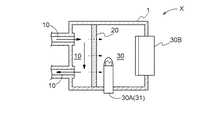
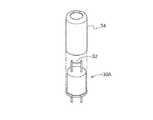
図1に示したように、本発明の触媒転化式センサXは、酸化によって生成した転化ガスを検出することで検知対象ガスを検知するべく、検知対象ガスを流下させるガス流路10と、ガス流路10と接続し、検知対象ガスを自然拡散させる拡散手段20によって隔てられた側に、加熱した触媒31と接触させることにより検知対象ガスを酸化して転化ガスを生成する加熱触媒部30A、および、酸化によって生成した転化ガスを検出可能なセンサ素子部30Bを有する転化部30と、を備える。Hereinafter, embodiments of the present invention will be described with reference to the drawings.
As shown in FIG. 1, the catalyst conversion type sensor X of the present invention has a
本実施形態では、検知対象ガスが三フッ化窒素であり、転化ガスが二酸化窒素であり、センサ素子部30Bが二酸化窒素を検知できる電気化学式窒素酸化物センサ素子である場合について説明するが、これらに限定されるものではない。例えば、センサ素子部30Bが電気化学式窒素酸化物センサ素子であれば、検知対象ガスをアンモニアとすることが可能である。また、センサ素子部30Bが転化ガスとして一酸化炭素や二酸化炭素を検知できるセンサ素子であれば、他のガスも検知対象とすることが可能である。 In the present embodiment, the case where the detection target gas is nitrogen trifluoride, the conversion gas is nitrogen dioxide, and the
拡散手段20は、ガス流路10と転化部30とを仕切るものであり、これらを空間的に区別できるように構成してあればよく、ガス流路10を流下する検知対象ガスが転化部30の側に自然拡散できるように検知対象ガスを透過させる態様となるように構成してある。即ち、ガス流路10を流下する検知対象ガスの一部は、そのままガス流路10の下流側へ流下し、残りの一部が拡散手段20を透過して転化部30の内部へ自然拡散する態様となる。本明細書における「自然拡散」とは、例えば検知対象ガスを加圧するなどして強制的に拡散手段20の孔を通過させて転化部30の内部へ透過させることはせず、ガス流路10を流下する検知対象ガスの少なくとも一部が、当該流圧の影響を受け難い状態で拡散手段20の孔を通過して転化部30の内部へ透過する態様のことをいうものとする。 The diffusion means 20 partitions the
このような拡散手段20は、透気抵抗度が800mm・Pa−1・s−1以下であるように構成すればよく、好ましくは、50〜800mm・Pa−1・s−1とするのがよい。Such diffusion means 20 may be configured to air resistance is a 800mm· Pa-1·s -1 or less, preferably, that the 50~800mm· Pa-1·s -1 Good.
拡散手段20は、異なる材料を組み合わせて構成してもよく、単一の材料で構成してもよい。本実施形態では異なる材料を組み合わせて構成した場合について説明する。 The diffusion means 20 may be composed of a combination of different materials, or may be composed of a single material. In this embodiment, a case where different materials are combined and configured will be described.
拡散手段20を異なる材料を組み合わせて構成する場合は、図2に示したように、所定の孔径を有する孔部21aを備えた樹脂膜21、および、ガス透過性の多孔質膜22を隣接配置して重ねた態様とすることができるが、これに限定されるものではない。これらを重ねる場合は、樹脂膜21がガス流路10の側、多孔質膜22が転化部30の側となるように配設すればよい。 When the diffusing means 20 is composed of a combination of different materials, as shown in FIG. 2, a
樹脂膜21は、プラスチック合成樹脂などの高分子成分などを薄い膜状に成型したものとすればよいが、これに限定されるものではない。このような樹脂膜21に所定の孔径を有する孔部21aを1個あるいは複数個形成する。孔部21aの孔径および孔数を設定することにより、拡散手段20を透過して転化部30の内部へ自然拡散する検知対象ガスのガス量を調節することができる。ガス量の調節は、所望のガス量となるように孔部21aの孔径および孔数を設定すればよい。 The
多孔質膜22は、ガス透過性の多孔質膜等を使用すればよいが、これに限定されるものではない。このような多孔膜は、例えばPTFE(ポリテトラフルオロエチレン)膜等を使用することができる。当該多孔質膜22は、検知対象ガスが転化部30の内部へ自然拡散する程度を所望の程度に規定することができる。 As the
上述したように、拡散手段20は、ガス流路10を流下する検知対象ガスが転化部30の側に自然拡散できるように検知対象ガスを透過させる態様となっているが、一方で、転化部30において生成した転化ガスが拡散手段20を透過してガス流路10の側に移行し難いように構成するのが望ましい。即ち、転化ガスがガス流路10の側に移行し難くなれば、センサ素子部30Bによって効率よく転化ガスを検知することができる。そのため、上述した拡散手段20であれば、孔部21aの孔径および孔数の他、孔部21aの配設位置を種々設定し、さらに多孔質膜22の透気度を種々変更する等して、拡散手段20の透気抵抗度が、適用される検知対象ガスが転化部30の側に自然拡散でき、かつ、転化ガスが転化部30からガス流路10の側に移行し難くなるように構成することができる。 As described above, the diffusion means 20 is in a mode of allowing the detection target gas to permeate so that the detection target gas flowing down the
例えば、拡散手段20を樹脂膜21およびガス透過性の多孔質膜22を重ねた態様とした場合、樹脂膜21の中心に1つの孔部21aを形成し、孔径を1〜4mmとした場合において転化率を35〜90%程度とすることができる。 For example, when the diffusion means 20 has a
拡散手段20を単一の材料で構成する場合は、例えば所定の孔径を有する孔部を形成した樹脂膜、或いは、ガス透過性の多孔質膜等の何れかを使用すればよいが、これに限定されるものではない。 When the diffusing means 20 is made of a single material, for example, a resin film having pores having a predetermined pore diameter, a gas-permeable porous membrane, or the like may be used. It is not limited.
樹脂膜は、上述したプラスチック合成樹脂などの高分子成分などを薄い膜状に成型したものとすればよいが、これに限定されるものではない。この場合も当該樹脂膜に所定の孔径を有する孔部を1個あるいは複数個形成する。孔部2の孔径および孔数を設定することにより、拡散手段20を透過して転化部30の内部へ自然拡散する検知対象ガスのガス量を調節することができる。そのため、所望のガス量となるように孔部の孔径および孔数を設定すればよい。例えば樹脂膜の外径を14mmとした場合、孔径を1〜4mmとするのがよい。 The resin film may be formed by molding a polymer component such as the plastic synthetic resin described above into a thin film, but the resin film is not limited thereto. Also in this case, one or a plurality of pores having a predetermined pore diameter are formed in the resin film. By setting the hole diameter and the number of holes of the
多孔質膜は、例えば上述したPTFE膜等を使用することができる。尚、拡散手段20を単一の材料で構成する場合は単一の同じ材料(多孔質PTFE膜)であっても、透気度を異ならせた複数の多孔質PTFE膜を組み合わせることも可能である。 As the porous membrane, for example, the above-mentioned PTFE membrane or the like can be used. When the diffusion means 20 is composed of a single material, it is possible to combine a plurality of porous PTFE membranes having different air permeability even if they are the same single material (porous PTFE membrane). is there.
本構成であれば、簡易な構成で、拡散手段20を透過して転化部30の内部へ自然拡散する検知対象ガスのガス量を調節することができる。ガス量の調節は、所望のガス量となるように孔部の孔径および孔数を設定すればよい。 With this configuration, it is possible to adjust the amount of the detection target gas that has passed through the diffusion means 20 and naturally diffuses into the inside of the
転化部30は、検知対象ガスを酸化して生成した転化ガスを検出するように構成するため、加熱触媒部30Aおよびセンサ素子部30Bを有する。本実施形態の転化部30はケーシング1の内部空間の一部として構成してある。即ち、当該ケーシング1は、その内部を拡散手段20によって仕切ってあり、仕切られた空間の一方を転化部30とし、他方をガス流路10の一部としてある。ケーシング1は円柱状や立方体状等、どのような形状であってもよい。本実施形態では、検知対象ガスがガス流路10を流下する方向と、検知対象ガスの一部が拡散手段20を透過して転化部30の内部へ自然拡散する方向とが異なる(略直交する)ように構成してある場合について説明する。この場合、ガス流路10を流下する検知対象ガスの少なくとも一部を、より当該流圧の影響を受け難い状態で拡散手段20の孔を通過して転化部30の内部へ自然拡散させ易くなる。 The
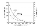
加熱触媒部30Aは、拡散手段20を透過して転化部30の内部へ自然拡散した検知対象ガスを加熱した触媒31に接触させ、検知対象ガスを酸化して転化ガスを生成する。本実施形態における当該触媒31は、PdおよびPtを含有する貴金属触媒とした場合について説明するが、これらに限定されずRu、RhおよびIrも使用することができる。この加熱触媒部30Aは、例えば300〜700℃、好ましくは350〜600℃、さらに好ましくは400〜600℃程度まで加熱することができるように構成すればよい。この場合、印加電圧は約0.68〜1.85Vとするのがよい。検知対象ガスが加熱した触媒31に接触すると、検知対象ガスが酸化され、また触媒による酸化作用によって転化ガスを生成することができる。加熱触媒部は1つであれば消費電力を抑制できるが、設置数は1つに限定されず、複数設けてもよい。加熱触媒部を複数設ける場合は、例えば2つの加熱触媒部を所定間隔で並置してそれらの下流側にセンサ素子部30Bが配設されるように構成してもよいし、2つの加熱触媒部がケーシング1の内部で対面するように配設してもよい。また、加熱触媒部を複数設ける場合は、それぞれの加熱触媒部を加熱する温度を同じ温度に設定してもよく、設置位置に応じた適切な温度に変更してもよい。当該温度は、拡散手段20の性能が適切に発揮できる温度に設定するのがよい。 The
本実施形態では、加熱触媒部30Aとして接触燃焼式センサの素子を用いる場合について説明する。この場合、簡便かつ小型の態様で加熱触媒部を構成することができる。 In this embodiment, a case where an element of a contact combustion type sensor is used as the
接触燃焼式センサは、所定のガスと感応する検知素子を備えている。当該検知素子は、接触燃焼式の素子であって、電気抵抗に対する温度係数が高い白金等を含む金属線のコイルの表面が、検出対象ガスに対して活性な貴金属触媒を坦持するアルミナ等の坦体で被覆されて形成されている。貴金属触媒は、上述した白金族である、Pt、Pd、Ru、RhおよびIrの少なくとも1つ以上の微粒子を使用することができる。 The contact combustion type sensor includes a detection element that is sensitive to a predetermined gas. The detection element is a contact combustion type element, and the surface of the coil of a metal wire containing platinum or the like having a high temperature coefficient with respect to electric resistance is made of alumina or the like carrying a noble metal catalyst active with respect to the gas to be detected. It is formed by being covered with a carrier. As the noble metal catalyst, at least one or more fine particles of Pt, Pd, Ru, Rh and Ir, which are the platinum group described above, can be used.
検知素子の球径は0.76〜1.08mmとするのがよく、好ましくは0.84〜1.00mmとするのがよい。この範囲であれば、検知対象ガスを酸化して転化ガスを生成する効率が優れたものとなる。 The ball diameter of the detection element is preferably 0.76 to 1.08 mm, preferably 0.84 to 1.00 mm. Within this range, the efficiency of oxidizing the detection target gas to generate conversion gas is excellent.
上述したように、本実施形態では、検知対象ガスが三フッ化窒素であり、転化ガスが二酸化窒素であるが、これは以下の化1〜化3の反応式によって転化が進行すると考えられる。 As described above, in the present embodiment, the detection target gas is nitrogen trifluoride and the conversion gas is nitrogen dioxide, and it is considered that the conversion proceeds by the following reaction formulas 1 to 3.

センサ素子部30Bは、電気化学式センサ、光センサ、半導体式ガスセンサ、接触燃焼式センサ等が適用できる。本実施形態では、貴金属担持カーボンを有して、生成した転化ガスである二酸化窒素を検知できる電気化学式窒素酸化物センサ素子である場合について説明する。 An electrochemical sensor, an optical sensor, a semiconductor gas sensor, a contact combustion type sensor, or the like can be applied to the
当該電気化学式窒素酸化物センサ素子は、ガス拡散電極からなる検知極、当該検知極に一体に接合されている補助相、常温溶融塩である電解液、検知極と同様の構成からなる対極をセンサケースに収容することによって構成することができる。検知極は金触媒を担持させたカーボン粉末(金担持カーボン)とバインダーとしてのポリ4フッ化エチレンとの混合物から形成してある。補助相は多孔性ニッケルシートの孔中に補助相材料である硝酸リチウムを充填して形成してある。このような電気化学式窒素酸化物センサ素子は、二酸化窒素に対しても感度が高い。 The electrochemical nitrogen oxide sensor element detects a detection electrode composed of a gas diffusion electrode, an auxiliary phase integrally bonded to the detection electrode, an electrolytic solution which is a molten salt at room temperature, and a counter electrode having the same configuration as the detection electrode. It can be configured by housing it in a case. The detection electrode is formed from a mixture of carbon powder supporting a gold catalyst (gold-supporting carbon) and polyethylene tetrafluoride as a binder. The auxiliary phase is formed by filling the pores of the porous nickel sheet with lithium nitrate, which is an auxiliary phase material. Such an electrochemical nitrogen oxide sensor element is also highly sensitive to nitrogen dioxide.
この金担持カーボンであれば、約10nm程度まで微粒子化することができるため、電気化学式窒素酸化物センサ素子を小型化することができる。また、金担持カーボンを微粒子化することで、表面積が増大して二酸化窒素に対しても感度を向上することができる。
本発明で使用する検知対象ガスである三フッ化窒素は、ガスセンサによる感度が低く、直接電気化学反応による検知ができないため、事前に酸化により二酸化窒素(NO2)に転化させることにより検知できる。Since this gold-supported carbon can be made into fine particles up to about 10 nm, the electrochemical nitrogen oxide sensor element can be miniaturized. Further, by making the gold-supported carbon into fine particles, the surface area can be increased and the sensitivity to nitrogen dioxide can be improved.
Nitrogen trifluoride, which is the gas to be detected used in the present invention, has low sensitivity by a gas sensor and cannot be detected directly by an electrochemical reaction. Therefore, it can be detected by converting it tonitrogen dioxide (NO 2) by oxidation in advance.
本発明の触媒転化式センサXは、検知対象ガスを吸引して流下させるポンプ、流量センサ、センサ素子部30Bが検知した結果に基づいて検知対象ガスの漏洩を判定する演算手段、警報レベル以上の検知対象ガスの濃度を継続して検知した場合に警報を発するように制御する警報手段(何れも図外)等と共に警報器やガス検知器の部材とすることができる。 The catalyst conversion type sensor X of the present invention is a pump for sucking and flowing down the gas to be detected, a flow sensor, a calculation means for determining leakage of the gas to be detected based on the result detected by the
本発明の触媒転化式センサXは、拡散手段20によりガス流路10を流下する検知対象ガスを転化部30の側に自然拡散させることができるため、転化部30へ移行する検知対象ガスのガス量がガス流路10を流下する流量に依存し難いように構成することができる。そのため、流量センサが劣化して経時的にガス流路10を流下する検知対象ガスの流量が変動した場合であっても、直ちに転化部30へ移行する検知対象ガスのガス量に影響し難くなるため、転化部30へ移行する検知対象ガスのガス量は変動し難くなる。従って、本発明の触媒転化式センサXにおいては、検知対象ガスを転化ガスに転化させる転化率は検知対象ガスの流量の影響を受け難くなるため、経時的に転化率が低下し難くなる。 In the catalyst conversion type sensor X of the present invention, the detection target gas flowing down the
上述した拡散手段20であれば、転化部30の内部に自然拡散して滞留する検知対象ガスを加熱触媒部30Aに効率よく接触させることができるため、転化率を35〜90%程度、好ましくは45〜90%程度に向上させることができる。このとき、検知対象ガスは加熱触媒部30Aによって酸化され、また触媒による酸化作用によって転化ガスを生成することができるため、加熱触媒部30Aの加熱温度を300〜700℃、好ましくは350〜600℃、さらに好ましくは400〜600℃、さらに好ましくは450℃程度に抑制することができる。この温度範囲であれば、応答速度および検出可能な感度の双方を両立させることができる。 With the diffusion means 20 described above, the detection target gas that naturally diffuses and stays inside the
上述した拡散手段20であれば、転化ガスが転化部30から外部(ガス流路10)に移行し難くなるように構成することができるため、転化部30の内部で滞留する転化ガスを効率よく安定してセンサ素子部30Bによって検知できる。 Since the above-mentioned diffusion means 20 can be configured so that the conversion gas does not easily move from the
また、本発明の触媒転化式センサXは、転化部30に加熱触媒部30Aおよびセンサ素子部30Bを有することにより、熱分解ユニットを増設する必要が無いため小型化を達成することができる。 Further, the catalyst conversion type sensor X of the present invention can achieve miniaturization because it is not necessary to add a thermal decomposition unit by having the
〔実施例1〕
本発明の実施例について説明する。
本発明の触媒転化式センサXを使用して転化率の変動について調べた。
検知対象ガスは三フッ化窒素とし、転化ガスは二酸化窒素とし、センサ素子部30Bを電気化学式窒素酸化物センサ素子とした。また、拡散手段20は、円形に形成した樹脂膜(プラスチック合成樹脂)21およびガス透過性の多孔質膜(PTFE膜)22を重ねた態様とし、樹脂膜21の中心に1つの孔部21aを形成した。当該孔部21aの孔径をφ1〜14mmまで種々変更した場合の転化率の変動について調べた。φ14mmは、円柱状の転化部30の直径に対応する大きさである。[Example 1]
Examples of the present invention will be described.
The variation of the conversion rate was investigated using the catalytic conversion type sensor X of the present invention.
The detection target gas was nitrogen trifluoride, the conversion gas was nitrogen dioxide, and the
流下させるガスは三フッ化窒素および二酸化窒素とし、それぞれを各別に流下させた。二酸化窒素を流下させるのは、孔部21aの孔径によって二酸化窒素がどのように挙動するかを確認するためである。結果を図3に示した。三フッ化窒素を流下させた場合は転化部30において生成した転化ガスである二酸化窒素のセンサ出力を測定した。二酸化窒素を流下させた場合は転化部30に自然拡散した二酸化窒素のセンサ出力を測定した。 The gas to be flowed down was nitrogen trifluoride and nitrogen dioxide, and each was flowed down separately. The reason why nitrogen dioxide is allowed to flow down is to confirm how nitrogen dioxide behaves depending on the pore size of the
この結果、二酸化窒素を流下させた場合は、孔径が大きい場合(φ8〜14)は、センサ出力が高いため転化部30に自然拡散し易いと認められた。しかし、この場合、転化部30から外部(ガス流路10)に移行し易くなる。 As a result, it was recognized that when nitrogen dioxide was allowed to flow down, when the pore diameter was large (φ8 to 14), the sensor output was high and the nitrogen dioxide was easily diffused into the
三フッ化窒素を流下させた場合は、孔径が大きい場合(φ8〜14)は、センサ出力が低いため転化率は10〜20%程度であった。これは、孔径が大きいため、三フッ化窒素から生成した転化ガスである二酸化窒素が転化部30から外部(ガス流路10)に移行し易いためであると考えられた。また、孔径が小さい場合(φ1〜4)は、センサ出力が高いため転化率は35〜90%程度となった。これは、これは、孔径が小さいため、三フッ化窒素から生成した転化ガスである二酸化窒素が転化部30から外部(ガス流路10)に移行し難いため、効率よく検知できたためであると考えられた。 When nitrogen trifluoride was allowed to flow down, the conversion rate was about 10 to 20% when the pore diameter was large (φ8 to 14) because the sensor output was low. It was considered that this is because nitrogen dioxide, which is a conversion gas generated from nitrogen trifluoride, easily moves from the
これより、樹脂膜21の中心に1つの孔部21aを形成した場合は、孔径を1〜4mmとした場合に良好な転化率(35〜90%程度)が得られると認められ、好ましくは孔径を1〜3mmとした場合に良好な転化率(45〜90%程度)が得られると認められた。 From this, it is recognized that when one
〔実施例2〕
本発明の触媒転化式センサXおよび従来センサを使用して三フッ化窒素を検知する際の感度について比較した。従来センサは、熱分解により三フッ化窒素を二酸化窒素に転化させることにより検知するため、検知対象ガスを予め増設の熱分解ユニットにより熱分解しセンサ部へ導入する構造を有するものを使用した。当該熱分解ユニットは公知の構成のユニットを使用した。[Example 2]
The sensitivities of detecting nitrogen trifluoride using the catalytic conversion type sensor X of the present invention and the conventional sensor were compared. Since the conventional sensor detects by converting nitrogen trifluoride into nitrogen dioxide by thermal decomposition, a sensor having a structure in which the gas to be detected is thermally decomposed by an additional thermal decomposition unit in advance and introduced into the sensor unit is used. As the thermal decomposition unit, a unit having a known configuration was used.
拡散手段20の透気抵抗度を50mm・Pa−1・s−1とし、樹脂膜21(樹脂膜径16mm、PPフィルム 厚さ0.2mm)の中心に1つの孔部21a(孔径6mm)を形成したものを使用し、多孔質膜を多孔質PTFE膜(巴川製紙所社製)とした。また、転化部30の容積を0.001m3とし、加熱触媒部30Aの加熱温度を450℃とした。さらに三フッ化窒素の濃度は16ppmとし、本発明の触媒転化式センサXおよび従来センサにおいてガス流路を流下させる流量は0.5L/分とした。それぞれのセンサによって三フッ化窒素を検知した結果を図4に示した。The air permeation resistance of the diffusion means 20 is 50 mm, Pa-1 , s-1, and one
この結果、本発明の触媒転化式センサXにおける三フッ化窒素の感度は、50秒経過後には0.30μA付近の高い値が得られたが、従来センサにおける三フッ化窒素の感度は、100秒経過後であっても0.15μA付近の低い値に留まった。よって、本発明の触媒転化式センサXは、高い転化率が達成できる高感度のセンサであると認められた。 As a result, the sensitivity of nitrogen trifluoride in the catalytic conversion type sensor X of the present invention was as high as around 0.30 μA after 50 seconds, but the sensitivity of nitrogen trifluoride in the conventional sensor was 100. Even after the lapse of seconds, it remained at a low value of around 0.15 μA. Therefore, the catalytic conversion type sensor X of the present invention was recognized as a highly sensitive sensor capable of achieving a high conversion rate.
〔実施例3〕
実施例2で使用した触媒転化式センサXにおける拡散手段20の透気抵抗度について調べた。拡散手段20の構成を種々変更することで透気抵抗度を種々変更し、応答速度の目安である60秒以内、より好ましくは30秒以内を考慮したうえで十分なガス感度が得られる透気抵抗度の範囲を決定した。拡散手段20の構成は、PPフィルムのみ(多孔質PTFEシートなし)とし、孔部21aの孔径をそれぞれ1mm、2mm、3mm、4mm、6mm、8mmおよび全開(14mm)とした。透気抵抗度は孔径が小さい順からそれぞれ50、100、150、300、800、1000、1200であった。結果を図5に示した。[Example 3]
The air permeation resistance of the diffusion means 20 in the catalyst conversion type sensor X used in Example 2 was investigated. By variously changing the configuration of the diffusion means 20, the air permeability resistance is variously changed, and sufficient gas sensitivity can be obtained in consideration of the response speed within 60 seconds, more preferably within 30 seconds. The range of resistance was determined. The structure of the diffusion means 20 was only a PP film (without a porous PTFE sheet), and the pore diameters of the
この結果、拡散手段の透気抵抗度が800mm・Pa−1・s−1以下であれば、好ましい応答速度(60秒以内)を満たす範囲であると認められた。さらに、拡散手段の透気抵抗度が50〜800mm・Pa−1・s−1の範囲であれば、十分なガス感度(25mV以上)を満たす範囲であると認められた。As a result, it was recognized that when the air permeation resistance of the diffusion means was 800 mm · Pa-1 · s-1 or less, it was within the range satisfying the preferable response speed (within 60 seconds). Further, when the air permeation resistance of the diffusing means was inthe range of 50 to 800 mm, Pa -1 , s-1 , it was recognized that the range satisfied sufficient gas sensitivity (25 mV or more).
〔実施例4〕
本発明の触媒転化式センサXにおいて、拡散手段20を、単一の材料で構成した樹脂膜とした場合(実施例4−1)、或いは、樹脂膜21および多孔質膜22を隣接配置して重ねた態様とした場合(実施例4−2)について、それぞれのガス感度および応答時間の関係について調べた。[Example 4]
In the catalyst conversion type sensor X of the present invention, when the diffusion means 20 is a resin film made of a single material (Example 4-1), or the
実施例4−1のセンサでは、膜径14mmの樹脂膜に2mmの孔径を有する孔部を形成した拡散手段20を使用した。実施例4−2のセンサでは、膜径が14mmであり4mmの孔径を有する孔部を形成した樹脂膜21および膜径が14mmの多孔質PTFE膜からなる拡散手段20を使用した。三フッ化窒素の濃度は16ppmとした。結果を図6に示した。 In the sensor of Example 4-1 the diffusion means 20 in which a hole having a pore diameter of 2 mm was formed in a resin film having a film diameter of 14 mm was used. In the sensor of Example 4-2, a diffusion means 20 composed of a
この結果、何れの実施例においても約100〜200秒において、約160〜210mVの高いガス感度が得られたと認められた。 As a result, it was recognized that a high gas sensitivity of about 160 to 210 mV was obtained in about 100 to 200 seconds in each of the examples.
〔実施例5〕
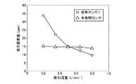
本発明の触媒転化式センサXおよび従来センサを使用して、ガス検知の際に得られる指示値が検知対象ガスの流量に依存するかどうかを調べた。従来センサは実施例2に使用した従来センサ1を使用した。
検知対象ガスは15ppmの三フッ化窒素とし、流量は0.2〜0.8L/分の間で種々変更した。結果を図7に示した。[Example 5]
Using the catalyst conversion type sensor X of the present invention and the conventional sensor, it was investigated whether or not the indicated value obtained at the time of gas detection depends on the flow rate of the gas to be detected. As the conventional sensor, the conventional sensor 1 used in the second embodiment was used.
The detection target gas was 15 ppm nitrogen trifluoride, and the flow rate was variously changed between 0.2 and 0.8 L / min. The results are shown in FIG.
この結果、従来センサ1は流量が増加するに従って転化率が減少するため指示値が減少したが、本発明の触媒転化式センサXは、流量が増加した場合であっても指示値は殆ど変化しなかった。そのため、本発明の触媒転化式センサXは、検知対象ガスの流量に依存し難いものと認められた。 As a result, in the conventional sensor 1, the indicated value decreases because the conversion rate decreases as the flow rate increases, but in the catalyst conversion type sensor X of the present invention, the indicated value almost changes even when the flow rate increases. There wasn't. Therefore, it was recognized that the catalyst conversion type sensor X of the present invention is less likely to depend on the flow rate of the gas to be detected.
〔実施例6〕
加熱触媒部30Aとして接触燃焼式センサを使用した場合に、当該接触燃焼式センサの検知素子の球径を種々変更した場合の印加電圧および素子温度の関係を調べた。[Example 6]
When a contact combustion type sensor was used as the
検知素子は白金コイルをPdおよびPtを含有する貴金属触媒を坦持するアルミナで被覆したものを使用し、検知素子の球径を、0.76mm(本発明例1)、0.84mm(本発明例2)、0.92mm(本発明例3)、1.00mm(本発明例4)、1.08mm(本発明例5)とし、印加電圧は約220〜1820mVの間で素子温度を測定した。結果を図8,9に示した。図9は印加電圧が900〜1300mVの間の図8のグラフを拡大したものである。 The detection element uses a platinum coil coated with alumina carrying a noble metal catalyst containing Pd and Pt, and the sphere diameter of the detection element is 0.76 mm (Example 1 of the present invention) and 0.84 mm (the present invention). Example 2), 0.92 mm (Example 3 of the present invention), 1.00 mm (Example 4 of the present invention), 1.08 mm (Example 5 of the present invention), and the applied voltage was measured between about 220 and 1820 mV. .. The results are shown in Figures 8 and 9. FIG. 9 is an enlarged graph of FIG. 8 in which the applied voltage is between 900 and 1300 mV.
この結果、印可電圧を高くするほど素子温度は上昇し、検知素子の球径を大きくするほど同一の電圧では素子温度が下がるものと認められた。 As a result, it was recognized that the higher the applied voltage, the higher the element temperature, and the larger the spherical diameter of the detection element, the lower the element temperature at the same voltage.
〔実施例7〕
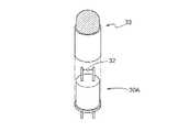
加熱触媒部30Aとして接触燃焼式センサを使用した場合、当該接触燃焼式センサの検知素子32を覆うキャップを、拡散制限を有しないキャップ33(図10,11:以下、拡散制限無しキャップと称する)、および、拡散制限を有するキャップ34(図12,13:以下、拡散制限付きキャップと称する)を使用したときに、検知素子32の球径がどのように関係するかを調べた。[Example 7]
When a contact combustion type sensor is used as the
拡散制限無しキャップ33は胴体部33aおよび金網部33bによって構成してある。胴体部33aは直径5.8〜5.9mmの裾広げ加工を施したSUS304製のシームレス管であり、金網部33bは最大直径が5.2mmとなる半円形状を呈しており、線径0.1mm、100メッシュであるSUS316製の金網が二重構造となるように構成してある。金網部33bは胴体部33aに対して4か所のスポット溶接を行って内嵌させ、これらを組み立てたときの長寸が11.5mmとなるようにしてある。拡散制限無しキャップ33は、例えば拡散制限無しキャップ33の内部のガスが拡散制限無しキャップ33の金網部33bを介して拡散するのを制限しないように構成してある。 The diffusion-restricted
一方、拡散制限付きキャップ34は直径5.9mm、長寸11.6mmの筒状のSUS305−2D製の胴体部34aを呈しており、直径3.6mmの孔部34bを形成してある。拡散制限付きキャップ34は当該孔部34bを胴体部34aの直径より絞った孔径とすることで、例えば拡散制限付きキャップ34の内部のガスが拡散制限付きキャップ34の孔部34bを介して拡散するのをある程度制限するように構成してある。 On the other hand, the diffusion-restricted
尚、拡散制限付きキャップ34は拡散制限無しキャップ33に比べて50%程度の拡散制限を有する構成となっている。 The diffusion-restricted
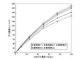
使用したガスは試験用のガスとしてメタンガスとした。メタンガスの濃度を0〜100%LELまで変化させた場合のガス感度の結果を図14(拡散制限無しキャップ33)、図15(拡散制限付きキャップ34)に示した。 The gas used was methane gas as a test gas. The results of gas sensitivity when the concentration of methane gas was changed from 0 to 100% LEL are shown in FIGS. 14 (
この結果、図14より拡散制限無しキャップ33を使用した場合は検知素子32の球径が大きくなるほど感度が高くなり、図15より拡散制限付きキャップ34を使用した場合は検知素子32の球径によって感度は殆ど変化しないことが判明した。これは、拡散制限付きキャップ34が有する拡散制限の作用のため、検知素子32の球径による感度の差が出難くなったと考えられる。これにより、拡散制限付きキャップ34を使用した場合は、例えば触媒の劣化による反応性の低下に際して、出力値に変化が生じ難く、感度の低下が小さいと認められた。 As a result, as shown in FIG. 14, when the
このように拡散制限付きキャップ34を使用した場合は感度の球径依存が殆ど無いため、拡散制限付きのキャップを使用すれば、加熱触媒部30Aにおいてガス拡散の状態が拡散律速となっていると考えられる。即ち、拡散制限付きキャップ34は、球径を意図的に変化させても感度に変化が生じない状態となるキャップであると考えられる。さらに、本実施例ではメタンガスを使用したが、メタンガスより分子が大きく拡散し辛いガスに対して、拡散制限付きキャップ34を使用した場合であっても、拡散律速となるキャップであると考えられる。 In this way, when the diffusion-restricted
〔実施例8〕
加熱触媒部30Aとして接触燃焼式センサを使用した場合に、当該接触燃焼式センサの検知素子の球径に対して、電気化学式窒素酸化物センサ素子(センサ素子部30B)におけるNO2感度の変化、および、応答速度について調べた。検知素子の球径は実施例6で設定した0.76〜1.08mmのサイズとし、接触燃焼式センサにおいて使用するキャップは実施例7で使用した2種類のキャップとした。検知対象ガスは16ppmの三フッ化窒素とし、印加電圧は1.1Vとした。結果を図16,17に示した。[Example 8]
When a contact combustion type sensor is used as the heating catalyst unit 30A, the change in NO 2 sensitivity of the electrochemical nitrogen oxide sensor element (
この結果、何れのキャップを使用した場合であっても、図16より検知素子の球径が大きくなるにつれて感度が上昇し、図17より球径が大きくなるにつれて応答速度が遅くなることが判明した。これらの結果より、感度と応答速度の兼ね合いから、検知素子の球径において実使用上の最適な範囲があると認められた。即ち、例えばNO2感度において例えば50mV以上(図16)が必要である場合、検知素子の球径は0.76〜1.08mmのサイズであれば、応答速度は約15〜34秒(図17)であり、検知対象ガスを酸化して転化ガスを生成する効率が優れ、好ましい応答速度(60秒以内)を満たす範囲であると認められた。As a result, it was found from FIG. 16 that the sensitivity increases as the ball diameter of the detection element increases, and the response speed decreases as the ball diameter increases from FIG. 17, regardless of which cap is used. .. From these results, it was confirmed that there is an optimum range for actual use in the ball diameter of the detection element from the balance between sensitivity and response speed. That is, for example, when NO2 sensitivity requires, for example, 50 mV or more (FIG. 16), if the ball diameter of the detection element is 0.76 to 1.08 mm, the response speed is about 15 to 34 seconds (FIG. 17). ), It was recognized that the efficiency of oxidizing the detection target gas to generate a conversion gas was excellent, and the response speed (within 60 seconds) was satisfied.
また、特に、検知素子の球径が0.84〜1.00mmであれば、NO2感度が50mV以上(図16)であり、かつ応答速度が30秒以内(図17)を満たす範囲であると認められた。Further, in particular, when the ball diameter of the detection element is 0.84 to 1.00 mm, the NO2 sensitivity is 50 mV or more (FIG. 16), and the response speed is within 30 seconds (FIG. 17). Was recognized.
〔実施例9〕
実施例8において、検知素子(加熱触媒部30A)の温度に対して、電気化学式窒素酸化物センサ素子(センサ素子部30B)におけるNO2感度の変化、および、応答速度について調べた。検知素子32の球径は1.00mmとした。結果を図18,19に示した。[Example 9]
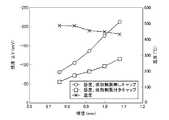
In Example 8, the change in NO 2 sensitivity of the electrochemical nitrogen oxide sensor element (
図18より、2種類のキャップにおいて検知素子のトップ温度は異なるものの、400〜420℃付近でセンサ出力がピークに達し、その後、検知素子の温度が高くなるに従ってセンサ出力が低下するものと認められた。即ち、例えばNO2感度において50mV以上が必要である場合、拡散制限無しキャップ33を使用した場合は検知素子の温度を300〜700℃とするのがよく、拡散制限付きキャップ34を使用した場合は検知素子の温度を300〜600℃とするのがよいことが判明した。From FIG. 18, it is recognized that although the top temperature of the detection element is different between the two types of caps, the sensor output reaches a peak around 400 to 420 ° C., and then the sensor output decreases as the temperature of the detection element increases. It was. That is, for example, when a NO2 sensitivity of 50 mV or more is required, the temperature of the detection element should be 300 to 700 ° C. when the diffusion-restricted
また、図19より、2種類のキャップにおいて、検知素子の温度が高いほど応答速度が速くなると認められた。即ち、拡散制限無しキャップ33を使用した場合は、300℃以上の場合が好ましい応答速度(60秒以内)を満たし、700℃付近から応答速度は殆ど変化が認められないため、検知素子の温度を300〜700℃とするのがよいことが判明した。また、拡散制限付きキャップ34を使用した場合は、約350℃以上の場合が好ましい応答速度(60秒以内)を満たし、600℃付近から応答速度は殆ど変化が認められないため、検知素子の温度を350〜600℃とするのがよいことが判明した。 Further, from FIG. 19, it was recognized that in the two types of caps, the higher the temperature of the detection element, the faster the response speed. That is, when the
検知素子の温度を300〜700℃とした場合、印加電圧は例えば0.68V(検知素子の球径0.76mm)〜1.85V(検知素子の球径1.08mm)とするのがよい(図8)。 When the temperature of the detection element is 300 to 700 ° C., the applied voltage is preferably, for example, 0.68V (ball diameter of the detection element 0.76 mm) to 1.85V (sphere diameter of the detection element 1.08 mm) (the ball diameter of the detection element is 1.08 mm). FIG. 8).
尚、拡散制限付きキャップ34を使用した場合においてトップ温度が低温にシフトし、応答速度が遅くなっているのは、ガスがキャップ内にこもるためであると考えられた。また、図18,19の結果より、検知素子の温度が300℃以下であれば検知対象ガスの転化が殆ど進行し難く、700℃以上の高温であれば、NOからN2O2となる反応が進行し難くなると考えられる。When the diffusion-restricted
〔実施例10〕
加熱触媒部30Aとして接触燃焼式センサを使用した場合に、当該接触燃焼式センサに使用するキャップを、拡散制限無しキャップ33(図10,11)、および、拡散制限付きキャップ34(図12,13)を使用したときの検知素子の経時安定性について調べた。使用したガスは15ppmの三フッ化窒素とした。結果を図20に示した。[Example 10]
When a contact combustion type sensor is used as the
この結果、約二か月以上使用した時点において、拡散制限無しキャップ33を使用した方は緩やかに劣化が進行し、拡散制限付きキャップ34を使用した方は殆ど劣化が認められないことが判明した。 As a result, it was found that when the
尚、拡散制限無しキャップ33を使用した方は経時的に劣化が緩やかに進行するがセンサ出力が高いため、短期使用できる場所であれば十分使用できると考えられる。一方、拡散制限付きキャップ34を使用した方はセンサ出力が低いがセンサ出力が経時的に安定しているため、工場など長期に亘って設置できる場所での使用に向いていると考えられる。 It should be noted that the person who uses the
〔実施例11〕
上述した実施例では、加熱触媒部30Aおよびセンサ素子部30Bは離間した状態で転化部30に配置する場合について説明したが、このような態様に限定されるものではなく、加熱触媒部30Aおよびセンサ素子部30Bを一体化した態様で転化部30に配置してもよい。[Example 11]
In the above-described embodiment, the case where the
例えば図21〜26に示したように、加熱触媒部30Aを構成する第一センサケース40と、センサ素子部30Bを構成する第二センサケース50とをボルト等によって一体化させる態様とすることが可能である。 For example, as shown in FIGS. 21 to 26, the
第一センサケース40には、ガスが流入する第一ガス流入口41と、接触燃焼式センサを差し込む差込孔42と、ガスが流出するガス流出口43とが形成してある(図21〜23)。ガス流入口41からは検知対象ガスが流入し、ガス流出口43からは転化ガスが流出する。 The
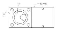
第二センサケース50には、電気化学式センサ等を収容するセンサ収容部51と、第一センサケース40を載置する載置部52とが形成してある(図24,25)。また、第二センサケース50には、載置部52においてガス流出口43と接続する第二ガス流入口53が形成してあり、当該第二ガス流入口53およびセンサ収容部51を連通させる連通部54が形成してある。これにより、ガス流出口43から流出した転化ガスが第二ガス流入口53および連通部54を介してセンサ収容部51に流入し、電気化学式センサ等によって転化ガスを検知できる。 The
このように、加熱触媒部30A(第一センサケース40)およびセンサ素子部30B(第二センサケース50)を一体化した態様とすることで、転化部30の容量を小さくすることができる。 In this way, the capacity of the
また、第二センサケース50に第一センサケース40を載置しない態様とすることで、センサ素子部30B(第二センサケース50)のみの構成、即ち、電気化学式センサのみの構成とすることができる。これにより、加熱触媒部30Aおよびセンサ素子部30Bを備えた構成と、センサ素子部30Bのみを備えた構成とを容易に選択することができる。 Further, by not mounting the
本発明は、酸化によって生成した転化ガスを検出することで検知対象ガスを検知する触媒転化式センサに利用できる。 INDUSTRIAL APPLICABILITY The present invention can be used for a catalytic conversion type sensor that detects a gas to be detected by detecting a conversion gas generated by oxidation.
X 触媒転化式センサ
10 ガス流路
20 拡散手段
30 転化部
30A 加熱触媒部
30B センサ素子部
31 触媒X Catalyst
Claims (8)
Translated fromJapanese前記検知対象ガスを流下させるガス流路と、
前記ガス流路と接続し、前記検知対象ガスを自然拡散させる拡散手段によって前記ガス流路と空間的に区別できるように仕切られた転化部と、を備え、
前記転化部は、加熱した触媒と接触させることにより前記検知対象ガスを酸化して転化ガスを生成する加熱触媒部、および、酸化によって生成した転化ガスを検出可能なセンサ素子部を有し、
前記検知対象ガスが前記ガス流路を流下する方向と、前記検知対象ガスの一部が前記拡散手段を透過して前記転化部の内部へ自然拡散する方向とが異なるように構成してある触媒転化式センサ。In order to detect the detection target gas by detecting the conversion gas generated by oxidation, in thecasing,
A gas flow path through whichthe gas to be detected flows down, and
It is provided witha conversion unit which is connected to the gas flow path and is partitioned so as to be spatially distinguishable from the gas flow path by a diffusion means for naturally diffusing the detection target gas.
The conversion unit, the heating catalyst unit for generating a shifted gas by oxidizing detection target gas, and the conversion gas generated by oxidationhave a sensor capable of detecting element by contact with a heatedcatalyst,
A catalystconfigured so that the direction in which the detection target gas flows down the gas flow path and the direction in which a part of the detection target gas permeates the diffusion means and naturally diffuses into the inside of the conversion portion. Convertible sensor.
Priority Applications (2)
| Application Number | Priority Date | Filing Date | Title |
|---|---|---|---|
| US15/775,701US10928339B2 (en) | 2015-11-13 | 2016-11-14 | Catalytic-conversion-type sensor |
| PCT/JP2016/083735WO2017082431A1 (en) | 2015-11-13 | 2016-11-14 | Catalytic-conversion-type sensor |
Applications Claiming Priority (2)
| Application Number | Priority Date | Filing Date | Title |
|---|---|---|---|
| JP2015223022 | 2015-11-13 | ||
| JP2015223022 | 2015-11-13 |
Related Child Applications (1)
| Application Number | Title | Priority Date | Filing Date |
|---|---|---|---|
| JP2020216818ADivisionJP7097947B2 (en) | 2015-11-13 | 2020-12-25 | Catalytic conversion type sensor |
Publications (2)
| Publication Number | Publication Date |
|---|---|
| JP2017096946A JP2017096946A (en) | 2017-06-01 |
| JP6851185B2true JP6851185B2 (en) | 2021-03-31 |
Family
ID=58817303
Family Applications (2)
| Application Number | Title | Priority Date | Filing Date |
|---|---|---|---|
| JP2016221959AActiveJP6851185B2 (en) | 2015-11-13 | 2016-11-14 | Catalytic conversion sensor and gas detector |
| JP2020216818AActiveJP7097947B2 (en) | 2015-11-13 | 2020-12-25 | Catalytic conversion type sensor |
Family Applications After (1)
| Application Number | Title | Priority Date | Filing Date |
|---|---|---|---|
| JP2020216818AActiveJP7097947B2 (en) | 2015-11-13 | 2020-12-25 | Catalytic conversion type sensor |
Country Status (2)
| Country | Link |
|---|---|
| JP (2) | JP6851185B2 (en) |
| CN (1) | CN108351323A (en) |
Families Citing this family (3)
| Publication number | Priority date | Publication date | Assignee | Title |
|---|---|---|---|---|
| JP7263933B2 (en)* | 2019-06-18 | 2023-04-25 | 株式会社アイシン | gas sensor |
| CN112415134A (en)* | 2020-10-13 | 2021-02-26 | 南通峥麒环保科技有限公司 | NF3 gas detection pretreatment furnace |
| JP7731853B2 (en)* | 2022-07-08 | 2025-09-01 | 株式会社東芝 | Sensors and Sensor Systems |
Family Cites Families (17)
| Publication number | Priority date | Publication date | Assignee | Title |
|---|---|---|---|---|
| JPS58103660A (en)* | 1981-12-16 | 1983-06-20 | Hitachi Ltd | Gas sensor for carbon monoxide |
| GB8928177D0 (en)* | 1989-12-13 | 1990-02-14 | City Tech | Flammable gas detection |
| JPH0823555B2 (en)* | 1993-06-25 | 1996-03-06 | 日本電気株式会社 | Nitrogen trifluoride detection device and method |
| JPH08170954A (en)* | 1994-08-08 | 1996-07-02 | Matsushita Seiko Co Ltd | Gas sensor |
| JP3450084B2 (en)* | 1995-03-09 | 2003-09-22 | 日本碍子株式会社 | Method and apparatus for measuring combustible gas components |
| JPH08292138A (en)* | 1995-04-24 | 1996-11-05 | Hirotaka Komiya | Device for detecting gas |
| WO2002076503A1 (en)* | 2000-06-20 | 2002-10-03 | Mayo Foundation For Medical Education And Research | Treatment of central nervous system diseases by antibodies against glatiramer acetate |
| JP3640601B2 (en)* | 2000-07-11 | 2005-04-20 | セントラル硝子株式会社 | Method for detecting fluorine-containing compound gas |
| JP4375336B2 (en)* | 2003-08-11 | 2009-12-02 | 株式会社日立製作所 | Gas sensor and gas detection method |
| JP2005214933A (en) | 2004-02-02 | 2005-08-11 | Shimadzu Corp | Hydrogen sensor |
| JP4156561B2 (en) | 2004-05-31 | 2008-09-24 | 東京瓦斯株式会社 | Combustible gas concentration measuring device |
| DE102005037529A1 (en)* | 2004-08-11 | 2006-02-23 | Gte Industrieelektronik Gmbh | Gas sensor for use in mixtures containing interfering gases has a heating element in the filter used in taking up the interfering gas |
| US7754491B2 (en)* | 2005-12-09 | 2010-07-13 | The Regents Of The University Of Calif. | Sensor for measuring syngas ratios under high temperature and pressure conditions |
| JP2009092431A (en)* | 2007-10-04 | 2009-04-30 | Denso Corp | Nox sensor |
| JP2013130540A (en) | 2011-12-22 | 2013-07-04 | New Cosmos Electric Corp | Gas detector |
| CN102914575A (en)* | 2012-08-14 | 2013-02-06 | 尚沃医疗电子无锡有限公司 | Gas sensor |
| CN103575918A (en)* | 2013-10-28 | 2014-02-12 | 邯郸派瑞节能控制技术有限公司 | Device and method for detecting nitrogen trifluoride |
- 2016
- 2016-11-14JPJP2016221959Apatent/JP6851185B2/enactiveActive
- 2016-11-14CNCN201680066293.0Apatent/CN108351323A/enactivePending
- 2020
- 2020-12-25JPJP2020216818Apatent/JP7097947B2/enactiveActive
Also Published As
| Publication number | Publication date |
|---|---|
| JP2021056244A (en) | 2021-04-08 |
| JP7097947B2 (en) | 2022-07-08 |
| CN108351323A (en) | 2018-07-31 |
| JP2017096946A (en) | 2017-06-01 |
Similar Documents
| Publication | Publication Date | Title |
|---|---|---|
| JP7097947B2 (en) | Catalytic conversion type sensor | |
| JP6596444B2 (en) | Electrochemical cell | |
| JP2006515401A (en) | Space-saving exhaust gas aftertreatment device that has exhaust and recirculation zones located in a nested manner and that allows exhaust gas to flow in and out on the same side | |
| CN113295742A (en) | Acrylonitrile detection using biased electrochemical sensors | |
| US10948452B2 (en) | Sensing electrode oxygen control in an oxygen sensor | |
| CN111380936A (en) | Electrochemical gas sensor assembly | |
| JP7141962B2 (en) | Constant potential electrolytic gas sensor | |
| US10928339B2 (en) | Catalytic-conversion-type sensor | |
| US20100040935A1 (en) | Fuel cell element electrode | |
| WO2017082431A1 (en) | Catalytic-conversion-type sensor | |
| JP6858535B2 (en) | Catalytic conversion sensor and gas detector | |
| JP7090756B2 (en) | Catalytic conversion type sensor | |
| JP7303617B2 (en) | gas sensor | |
| JP4084345B2 (en) | Combustible gas concentration measuring device | |
| CN112924501A (en) | Electrochemical gas sensor assembly | |
| JP3042616B2 (en) | Constant potential electrolytic gas sensor | |
| KR101693531B1 (en) | A nitrogen oxide sensor | |
| JP4304024B2 (en) | Constant-potential electrolysis gas sensor | |
| KR101995498B1 (en) | Sensor material deposited with a metal oxide and gas sensors including the same | |
| JP7474682B2 (en) | Potential electrolysis gas sensor | |
| JP7478648B2 (en) | Potential electrolysis gas sensor | |
| CN219830930U (en) | Electrochemical gas sensor | |
| JP6330213B2 (en) | Constant potential electrolytic oxygen gas sensor | |
| JP2009301849A (en) | Fuel cell stack | |
| JP2003028831A (en) | Hydrogen gas concentration detector |
Legal Events
| Date | Code | Title | Description |
|---|---|---|---|
| A621 | Written request for application examination | Free format text:JAPANESE INTERMEDIATE CODE: A621 Effective date:20190902 | |
| A131 | Notification of reasons for refusal | Free format text:JAPANESE INTERMEDIATE CODE: A131 Effective date:20200519 | |
| A521 | Request for written amendment filed | Free format text:JAPANESE INTERMEDIATE CODE: A523 Effective date:20200622 | |
| A02 | Decision of refusal | Free format text:JAPANESE INTERMEDIATE CODE: A02 Effective date:20201013 | |
| A521 | Request for written amendment filed | Free format text:JAPANESE INTERMEDIATE CODE: A523 Effective date:20201225 | |
| C60 | Trial request (containing other claim documents, opposition documents) | Free format text:JAPANESE INTERMEDIATE CODE: C60 Effective date:20201225 | |
| A911 | Transfer to examiner for re-examination before appeal (zenchi) | Free format text:JAPANESE INTERMEDIATE CODE: A911 Effective date:20210107 | |
| C21 | Notice of transfer of a case for reconsideration by examiners before appeal proceedings | Free format text:JAPANESE INTERMEDIATE CODE: C21 Effective date:20210112 | |
| TRDD | Decision of grant or rejection written | ||
| A01 | Written decision to grant a patent or to grant a registration (utility model) | Free format text:JAPANESE INTERMEDIATE CODE: A01 Effective date:20210209 | |
| A61 | First payment of annual fees (during grant procedure) | Free format text:JAPANESE INTERMEDIATE CODE: A61 Effective date:20210309 | |
| R150 | Certificate of patent or registration of utility model | Ref document number:6851185 Country of ref document:JP Free format text:JAPANESE INTERMEDIATE CODE: R150 | |
| R250 | Receipt of annual fees | Free format text:JAPANESE INTERMEDIATE CODE: R250 | |
| R250 | Receipt of annual fees | Free format text:JAPANESE INTERMEDIATE CODE: R250 |