JP6850739B2 - Radio terminal station position estimation method and wireless base station - Google Patents
Radio terminal station position estimation method and wireless base stationDownload PDFInfo
- Publication number
- JP6850739B2 JP6850739B2JP2018005797AJP2018005797AJP6850739B2JP 6850739 B2JP6850739 B2JP 6850739B2JP 2018005797 AJP2018005797 AJP 2018005797AJP 2018005797 AJP2018005797 AJP 2018005797AJP 6850739 B2JP6850739 B2JP 6850739B2
- Authority
- JP
- Japan
- Prior art keywords
- terminal station
- wireless terminal
- measurement signal
- distributed
- radio wave
- Prior art date
- Legal status (The legal status is an assumption and is not a legal conclusion. Google has not performed a legal analysis and makes no representation as to the accuracy of the status listed.)
- Active
Links
Images


Landscapes
- Position Fixing By Use Of Radio Waves (AREA)
Description
Translated fromJapanese本発明は、分散配置される分散アンテナの切り替えが可能な無線基地局において、分散アンテナごとに当該無線基地局と無線端末局との間の電波到達時間を測定することで無線端末局の位置を推定する無線端末局の位置推定方法および無線基地局に関する。 The present invention determines the position of a wireless terminal station by measuring the radio wave arrival time between the wireless base station and the wireless terminal station for each distributed antenna in a wireless base station capable of switching distributed antennas. The present invention relates to a method of estimating the position of a wireless terminal station to be estimated and a wireless base station.
無線信号の電波到達時間であるToA(Time of Arrival )を応用したサービスとして、無線LANシステムにおける無線端末局の位置提供サービスがある。この位置提供サービスの実現例として、例えば非特許文献1に示すように、位置推定を行いたい無線端末局と複数の無線基地局との間で電波到達時間を測定する方法がある。 As a service that applies ToA (Time of Arrival), which is the radio wave arrival time of a wireless signal, there is a location providing service of a wireless terminal station in a wireless LAN system. As an example of realizing this location providing service, as shown in Non-Patent Document 1, for example, there is a method of measuring the radio wave arrival time between a wireless terminal station for which location estimation is desired and a plurality of wireless base stations.
図4は、従来の無線端末局の位置推定方法を示す。
図4において、無線端末局40の周辺に複数の無線基地局50−1〜50−3が存在する。無線端末局40は、まず無線基地局50−1との接続処理を行い(S11)、無線基地局50−1に測定信号を送信し、無線基地局50−1から応答信号を受信する(S12)。この無線端末局40の測定信号の送信開始時刻と、無線基地局50−1からの応答信号の受信開始時刻から往復遅延時間Tm1を測定する。無線端末局40は、同様に他の無線基地局50−2,50−3との接続処理を行い、それぞれ測定信号の送信開始時刻と応答信号の受信開始時刻から往復遅延時間Tm2,Tm3を算出する(S13〜S16)。さらに、無線端末局40は、各無線基地局50−1〜50−3との間の往復遅延時間Tm1〜Tm3から、それぞれの電波到達時間T1 〜T3 を算出する。そして、複数の無線基地局50−1〜50−3の位置情報と各電波到達時間T1 〜T3 から、無線端末局40の位置を推定する(S17)。FIG. 4 shows a conventional method for estimating the position of a wireless terminal station.
In FIG. 4, there are a plurality of radio base stations 50-1 to 50-3 around the
図4に示す従来の無線端末局の位置推定方法では、位置推定を行いたい無線端末局40と複数の無線基地局50−1〜50−3との間の電波到達時間T1 〜T3 を算出するために、無線端末局40は、複数の無線基地局50−1〜50−3に順番に接続する必要があり、その接続処理に無線基地局数分の時間がかかっていた。 In the conventional position estimation method of the wireless terminal station shown in FIG. 4, the radio wave arrival times T1 to T3 between the
本発明は、無線基地局で分散配置される分散アンテナを切り替えながら無線基地局と無線端末局との間の電波到達時間を測定することで、高速に無線端末局の位置推定を行うことができる無線端末局の位置推定方法および無線基地局を提供することを目的とする。 According to the present invention, the position of a wireless terminal station can be estimated at high speed by measuring the arrival time of radio waves between the wireless base station and the wireless terminal station while switching the distributed antennas distributed in the wireless base station. An object of the present invention is to provide a method for estimating the position of a radio terminal station and a radio base station.
第1の発明は、分散配置される複数の分散アンテナを切り替えて送受信が可能な無線基地局と、該無線基地局と通信する無線端末局とを備え、該無線基地局が該無線端末局の位置を推定する無線端末局の位置推定方法において、無線基地局が、分散アンテナごとに、測定信号を送信し、該測定信号を受信した無線端末局から送信された応答信号を受信することで、当該無線端末局との間の電波到達時間を測定する第1ステップと、第1ステップで測定した分散アンテナごとの電波到達時間を用いて無線端末局の位置を推定する第2ステップとを実行し、第1ステップは、分散アンテナごとに、測定信号の送信から応答信号の受信までの往復遅延時間を、無線端末局が受信する反射成分を削減するように測定信号の送信電力を低減して、または無線端末局が反射成分の少なくとも一部を受信しないように測定信号の変調方式・符号化率を変更して複数測定するステップと、分散アンテナごとに、複数測定された往復遅延時間を平均化した値から電波到達時間を算出するステップとを含む。The first invention includes a radio base station capable of switching and transmitting and receiving a plurality of distributed antennas arranged in a distributed manner, and a radio terminal station that communicates with the radio base station, and the radio base station is the radio terminal station. In the position estimation method of a wireless terminal station for estimating the position, the wireless base station transmits a measurement signal for each distributed antenna and receives a response signal transmitted from the wireless terminal station that has received the measurement signal. The first step of measuring the radio wave arrival time with the wireless terminal station and the second step of estimating the position of the wireless terminal station using the radio wave arrival time of each distributed antenna measured in the first step are executed. the first step is distributed for each antenna, the round trip time between the transmission of the measurement signal and receiving the response signal,by reducing the transmission power of the measurement signalas a wireless terminal station to reduce the reflection component for receiving,Alternatively, the step of changing the modulation method / codingrate of the measurement signal so that the wireless terminal station does not receive at least a part of the reflected component and performing multiple measurements, and the multiple measured round-trip delay times are averaged for each distributed antenna. It includes a step of calculating the radio wave arrival time from the calculated value.
第1の発明の無線端末局の位置推定方法において、第1ステップでは、分散アンテナごとに接続されるケーブルの長さによる遅延時間を校正する。In the position estimation method of a wireless terminal station of the first invention,in a first step,we calibrate the delay time due to the length of the cable connected to each distributedantenna.
第1の発明の無線端末局の位置推定方法において、第1ステップでは、無線端末局の内部における時間ずれを校正する。In the position estimation method of a wireless terminal station of the first invention,in a first step,we calibrated time shift in the interior of the radio terminalstation.
第1の発明の無線端末局の位置推定方法において、第1ステップでは、他無線局からの干渉による電波到達時間ずれを校正する。In the position estimation method of a wireless terminal station of the first invention,in a first step,we calibrate the radio wave arrival time difference due to interference from other radiostations.
第2の発明の無線基地局は、所定の長さを有するケーブルを介して分散配置される複数の分散アンテナと、無線端末局との電波到達時間を測定するための測定信号を送信する測定信号送信部と、測定信号を受信した無線端末局から送信された応答信号を受信する応答信号受信部と、複数の分散アンテナを切り替え、該切り替えた分散アンテナと測定信号送信部および応答信号受信部とを接続するアンテナ切替部と、分散アンテナごとに、測定信号の送信から応答信号の受信までの往復遅延時間を、無線端末局が受信する反射成分を削減するように測定信号の送信電力を低減して、または無線端末局が反射成分の少なくとも一部を受信しないように測定信号の変調方式・符号化率を変更して複数測定する往復遅延時間測定部と、分散アンテナごとに、複数測定された往復遅延時間を平均化した値から電波到達時間を算出する電波到達時間算出部と、分散アンテナごとの電波到達時間から無線端末局の位置を推定する位置推定部とを備える。
The radio base station of the second invention is a measurement signal that transmits a measurement signal for measuring a radio wave arrival time between a plurality of distributed antennas distributed and arranged via a cable having a predetermined length and a radio terminal station. A transmitter, a response signal receiver that receives a response signal transmitted from a wireless terminal station that has received the measurement signal, and a plurality of distributed antennas that are switched, and the switched distributed antenna, the measurement signal transmitter, and the response signal receiver an antenna switching unit for connecting, for each distributed antenna, the round trip time between the transmission of the measurement signal and receiving the response signal,reducing the transmit power of the measuring signalas a wireless terminal station to reduce the reflection component that receivesIn addition , a reciprocating delay time measuring unit that measures a plurality of measurements by changing the modulation method / codingrateof the measured signal so that the wireless terminal station does not receive at least a part of the reflected component, and a plurality of measurements are performed for each distributed antenna. It includes a radio wave arrival time calculation unit that calculates the radio wave arrival time from the average value of the round-trip delay time, and a position estimation unit that estimates the position of the wireless terminal station from the radio wave arrival time for each distributed antenna.
本発明は、分散配置される複数の分散アンテナを切り替えながら、無線基地局と無線端末局との間で送受信する測定信号および応答信号から電波到達時間を測定することにより、高速に無線端末局の位置推定することができる。 According to the present invention, the radio wave arrival time is measured from the measurement signal and the response signal transmitted and received between the wireless base station and the wireless terminal station while switching the plurality of distributed antennas arranged in a distributed manner, thereby performing the wireless terminal station at high speed. The position can be estimated.
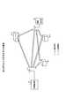
図1は、本発明における無線端末局の位置推定方法を示す。
図1において、無線基地局10には、分散配置される分散アンテナ11−1〜11−3が接続される。ここでは、分散アンテナが3本の例を示すが、3本以上であってもよい。無線基地局10と各分散アンテナ11−1〜11−3は、所定の長さを有するケーブル12−1〜12−3を介して接続され、各分散アンテナ11−1〜11−3の位置を(x1,y1)、(x2,y2)、(x3,y3)とする。FIG. 1 shows a method for estimating the position of a wireless terminal station in the present invention.
In FIG. 1, distributed antennas 11-1 to 11-3, which are distributed and arranged, are connected to the
無線基地局10は、分散アンテナ11−1〜11−3を介して無線端末局20との接続処理を行い、無線端末局20の位置情報の収集を開始する(S1)。 The
無線基地局10は、まず分散アンテナ11−1に切り替え、無線端末局20に対して測定信号を送信し、測定信号を受信した無線端末局20は、無線基地局10に対して応答信号を送信する(S2)。ここで、無線基地局10は、測定信号の送信開始時刻と応答信号の受信開始時刻を測定し、往復遅延時間Tm1を取得する。この往復遅延時間Tm1には、接続されるケーブル12−1の往復で発生する遅延時間2Tc1および測定信号の信号長Ts が含まれているので、無線基地局10の分散アンテナ11−1と無線端末局20との間の電波到達時間T1 は、次式で求めることができる。
T1 =(Tm1−2Tc1−Ts )/2 …(1)The
T1 = (Tm1-2Tc1-Ts) / 2 ... (1)
次に、無線基地局10は、分散アンテナ11−2,11−3に順次切り替え、無線端末局20に対して測定信号を送信し、測定信号を受信した無線端末局20は無線基地局10に対して応答信号を送信し(S3,S4)、往復遅延時間Tm2,Tm3を測定する。ここで、分散アンテナ11−2,11−3と無線端末局20との間の電波到達時間T2 ,T3 は、ケーブル12−2,12−3の往復で発生する遅延時間2Tc2,2Tc3と、測定信号の信号長Ts を用いて、次式で求めることができる。
T2 =(Tm2−2Tc2−Ts )/2 …(2)
T3 =(Tm3−2Tc3−Ts )/2 …(3)Next, the
T2 = (Tm2-2Tc2-Ts) / 2 ... (2)
T3 = (Tm3-2Tc3-Ts) / 2 ... (3)
次に、無線基地局10は、得られた各分散アンテナ11−1〜11−3に対する電波到達時間T1 〜T3 から、無線基地局10と各分散アンテナ11−1〜11−3との間の距離R1 〜R3 に換算し、無線端末局20の位置(x,y)を次式を用いて推定する(S5)。
R1 ={ (x−x1)2+ (y−y1)2}1/2+cΔt …(4-1)
R2 ={ (x−x2)2+ (y−y2)2}1/2+cΔt …(4-2)
R3 ={ (x−x3)2+ (y−y3)2}1/2+cΔt …(4-3)Next, the
R1 = {(x−x1 )2 + (y−y1 )2 }1/2 + cΔt… (4-1)
R2 = {(x−x2 )2 + (y−y2 )2 }1/2 + cΔt… (4-2)
R3 = {(x−x3 )2 + (y−y3 )2 }1/2 + cΔt… (4-3)
ここで、cは光速、Δtは無線端末局20内で測定信号を受信して応答信号を送信するまでの遅延時間である。なお、当該遅延時間Δtは、式(1) 〜式(3) の電波到達時間T1 〜T3 で調整してもよい。式(4-1) 〜式(4-3) から無線端末局20の位置(x,y)を算出する方法は様々あるが、例えばニュートン法を用いることで、(x,y)を算出することができる。この例では、2次元上での位置を想定しているが、分散アンテナ数を増加させることで、3次元上においても無線端末局20の位置を推定することができる。 Here, c is the speed of light, and Δt is the delay time from receiving the measurement signal to transmitting the response signal in the
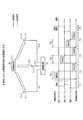
図2は、本発明における無線基地局10および無線端末局20の構成例を示す。なお、図中には、本発明に関係する主要な機能ブロックのみを抽出して示しており、一般的に無線基地局および無線端末局でも用いられる機能ブロックおよびその説明は省略している。 FIG. 2 shows a configuration example of the
図2において、無線基地局10は、分散アンテナ11−1〜11−n(nは3以上の整数)、ケーブル12−1〜12−n、アンテナ切替部13、測定信号送信部14、応答信号受信部15、往復遅延時間測定部16、電波到達時間算出部17、位置推定部18から構成される。 In FIG. 2, the
分散アンテナ11−1〜11−nは、アンテナ切替部13からケーブル12−1〜12−nを介して入力する測定信号を空中に送信し、空中から受信した応答信号をケーブル12−1〜12−nを介しアンテナ切替部13に出力する。 The distributed antennas 11-1 to 11-n transmit the measurement signal input from the
アンテナ切替部13は、測定信号送信部14から測定信号が入力される場合に、指定された分散アンテナ11−1〜11−nの1つに切り替えて出力する。また、指定された分散アンテナで受信する応答信号を応答信号受信部15に出力する。 When the measurement signal is input from the measurement
測定信号送信部14は、無線基地局10および無線端末局20の間の往復遅延時間を測定するための測定信号を生成し、アンテナ切替部13に出力する。また、測定信号の送信開始時刻を往復遅延時間測定部16に出力する。 The measurement
応答信号受信部15は、分散アンテナから送信された測定信号を無線端末局20が受信し、測定信号に対する応答信号が送信された場合に、その応答信号を受信し、その受信開始時刻を往復遅延時間測定部16に出力する。 When the
往復遅延時間測定部16は、測定信号送信部14から入力する送信開始時刻と、応答信号受信部15から入力される受信開始時刻の差分を算出し、往復遅延時間Tm1〜Tmnとして電波到達時間算出部17に出力する。 The round-trip delay
電波到達時間算出部17は、往復遅延時間測定部16から入力する往復遅延時間Tm1〜Tmnから、例えば式(1) 〜式(3) で示される各種の時間ずれを校正し、分散アンテナ11−1〜11−nと無線端末局20との間の電波到達時間T1 〜Tn を位置推定部18に出力する。 The radio wave arrival time calculation unit 17 calibrates various time lags represented by, for example, equations (1) to (3) from the round trip delay times Tm1 to Tmn input from the round trip delay
位置推定部18では、電波到達時間算出部17から入力される分散アンテナごとの電波到達時間T1 〜Tn から、例えば式(4-1) 〜式(4-3) を用いて無線端末局20の位置を推定する。 In the
無線端末局20は、アンテナ21、測定信号受信部22、応答信号送信部23から構成される。
アンテナ21は、受信した測定信号を測定信号受信部22に出力し、応答信号送信部23から入力される応答信号を空中に送信する。The
The
測定信号受信部22は、アンテナ21から入力される測定信号を受信し、その情報を応答信号送信部23に出力する。
応答信号送信部23では、測定信号受信部22から入力する測定信号に対する無線基地局10への応答信号を生成し、アンテナ21に出力する。The measurement
The response
ところで、式(1) 〜式(3) で示した分散アンテナ11−1〜11−3ごとに算出される電波到達時間T1 〜T3 には、他無線局からの干渉信号によるずれも存在する可能性がある。例えば、無線端末局20が応答信号を送信する際に、他無線局からの干渉によって送信待機が発生し、送信が遅れる場合がある。このように干渉信号によって正常に応答信号の送受信ができない場合があるため、電波到達時間に異常値が検出された場合は、その値を削除することによって、干渉による影響を削除する。 By the way, the radio wave arrival times T1 to T3 calculated for each of the distributed antennas 11-1 to 11-3 represented by the equations (1) to (3) may have a deviation due to an interference signal from another radio station. There is sex. For example, when the
また、電波到達時間T1 〜T3 を高精度に算出するために、分散アンテナ11−1〜11−3ごとに測定信号の送信形式を変更する方法が有効である。その具体例を図3を参照して説明する。 Further, in order to calculate the radio wave arrival times T1 to T3 with high accuracy, it is effective to change the transmission format of the measurement signal for each of the distributed antennas 11-1 to 11-3. A specific example thereof will be described with reference to FIG.
図3は、無線基地局10に接続される1つの分散アンテナ11のみを示し、送信形式を変更せず、分散アンテナ11と無線端末局20との間の往復遅延時間を測定する例を示す。ただし、本環境における伝搬路は、直接成分、反射物30−1による第1反射成分、反射物30−2による第2反射成分、反射物30−3による第3反射成分の4種類となり、往復遅延時間は4種類の合成波から算出される。なお、往復遅延時間は反射成分が存在するほど測定誤差が増加する傾向にある。 FIG. 3 shows an example in which only one distributed
ここで、無線基地局10から送信する測定信号の送信電力を低減した場合には、例えば無線基地局10から遠い反射物30−2で測定信号の反射波が小さくなり、この反射成分を削減できる。 Here, when the transmission power of the measurement signal transmitted from the
また、無線基地局10から送信する測定信号の変調方式および符号化率を変更することにより、無線端末局20における必要な受信感度を変更することができ、3種類の反射成分の一部または全部の受信可否を選択できる。 Further, by changing the modulation method and the coding rate of the measurement signal transmitted from the
また、無線基地局10から送信する測定信号の伝送帯域もしくは伝送周波数を調整する方法がある。一般的に、伝送周波数や伝送帯域によって伝搬路が異なることが知られている。したがって、複数の周波数や伝送帯域によって異なる伝搬路の往復遅延時間を測定することができる。 Further, there is a method of adjusting the transmission band or the transmission frequency of the measurement signal transmitted from the
このように、送信電力、変調方式・符号化率、周波数・伝送帯域を変更することで、伝搬路の反射環境が変更されるため、それらの往復遅延時間を平均化(重み付き平均も含む)することによって、電波到達時間を高精度に算出することができる。 By changing the transmission power, modulation method / coding rate, frequency / transmission band in this way, the reflection environment of the propagation path is changed, so the round-trip delay times are averaged (including the weighted average). By doing so, the radio wave arrival time can be calculated with high accuracy.
10,50 無線基地局
11 分散アンテナ
12 ケーブル
13 アンテナ切替部
14 測定信号送信部
15 応答信号受信部
16 往復遅延時間測定部
17 電波到達時間算出部
18 位置推定部
20,40 無線端末局
21 アンテナ
22 測定信号受信部
23 応答信号送信部
30 反射物10,50
Claims (5)
Translated fromJapanese前記無線基地局が、
前記分散アンテナごとに、測定信号を送信し、該測定信号を受信した前記無線端末局から送信された応答信号を受信することで、当該無線端末局との間の電波到達時間を測定する第1ステップと、
前記第1ステップで測定した前記分散アンテナごとの電波到達時間を用いて前記無線端末局の位置を推定する第2ステップと
を実行し、
前記第1ステップは、
前記分散アンテナごとに、前記測定信号の送信から前記応答信号の受信までの往復遅延時間を、前記無線端末局が受信する反射成分を削減するように前記測定信号の送信電力を低減して、または前記無線端末局が反射成分の少なくとも一部を受信しないように前記測定信号の変調方式・符号化率を変更して複数測定するステップと、
前記分散アンテナごとに、複数測定された前記往復遅延時間を平均化した値から前記電波到達時間を算出するステップと
を含むことを特徴とする無線端末局の位置推定方法。A wireless terminal that includes a wireless base station capable of transmitting and receiving by switching a plurality of distributed antennas arranged in a distributed manner and a wireless terminal station that communicates with the wireless base station, and the wireless base station estimates the position of the wireless terminal station. In the station position estimation method,
The radio base station
A first method of measuring the radio wave arrival time with the wireless terminal station by transmitting a measurement signal for each of the distributed antennas and receiving a response signal transmitted from the wireless terminal station that received the measurement signal. Steps and
The second step of estimating the position of the wireless terminal station using the radio wave arrival time for each distributed antenna measured in the first step is executed.
The first step is
For each of the distributed antennas, the round-trip delay time from the transmission of the measurement signal to the reception of the response signalis reduced , or the transmission powerof the measurement signal is reduced so as to reduce the reflection component received by the wireless terminal station, or A step of changing the modulation method / codingrate of themeasurement signal so that the wireless terminal station does not receive at least a part of the reflection component and performing a plurality of measurements.
A method for estimating the position of a wireless terminal station, which comprises a step of calculating the radio wave arrival time from a value obtained by averaging the reciprocating delay times measured in a plurality of measurements for each of the distributed antennas.
前記第1ステップでは、前記分散アンテナごとに接続されるケーブルの長さによる遅延時間を校正する
ことを特徴とする無線端末局の位置推定方法。In the method for estimating the position of a wireless terminal station according to claim 1,
In the first step, the position estimation method of a wireless terminal station, whereinyou calibrate the delay time due to the length of the cable connected to each of the distributed antenna.
前記第1ステップでは、前記無線端末局の内部における時間ずれを校正する
ことを特徴とする無線端末局の位置推定方法。In the method for estimating the position of a wireless terminal station according to claim 1,
In the first step, the position estimation method of a wireless terminal station, whereinyou calibrated time shift in the interior of the radio terminal station.
前記第1ステップでは、他無線局からの干渉による電波到達時間ずれを校正する
ことを特徴とする無線端末局の位置推定方法。In the method for estimating the position of a wireless terminal station according to claim 1,
In the first step, the position estimation method of a wireless terminal station, whereinyou calibrate the radio wave arrival time difference due to interference from other radio stations.
無線端末局との電波到達時間を測定するための測定信号を送信する測定信号送信部と、 前記測定信号を受信した前記無線端末局から送信された応答信号を受信する応答信号受信部と、
前記複数の分散アンテナを切り替え、該切り替えた分散アンテナと前記測定信号送信部および前記応答信号受信部とを接続するアンテナ切替部と、
前記分散アンテナごとに、前記測定信号の送信から前記応答信号の受信までの往復遅延時間を、前記無線端末局が受信する反射成分を削減するように前記測定信号の送信電力を低減して、または前記無線端末局が反射成分の少なくとも一部を受信しないように前記測定信号の変調方式・符号化率を変更して複数測定する往復遅延時間測定部と、
前記分散アンテナごとに、複数測定された前記往復遅延時間を平均化した値から電波到達時間を算出する電波到達時間算出部と、
前記分散アンテナごとの前記電波到達時間から前記無線端末局の位置を推定する位置推定部と
を備えたことを特徴とする無線基地局。A plurality of distributed antennas distributed via a cable having a predetermined length,
A measurement signal transmitter that transmits a measurement signal for measuring the radio wave arrival time with a wireless terminal station, a response signal receiver that receives a response signal transmitted from the wireless terminal station that has received the measurement signal, and a response signal receiver.
An antenna switching unit that switches the plurality of distributed antennas and connects the switched distributed antenna to the measurement signal transmitting unit and the response signal receiving unit.
For each of the distributed antennas, the round-trip delay time from the transmission of the measurement signal to the reception of the response signalis reduced , or the transmission powerof the measurement signal is reduced so as to reduce the reflection component received by the wireless terminal station, or A reciprocating delay time measuring unit that measures a plurality of measurement signals by changing the modulation method / codingrate of themeasurement signal so that the wireless terminal station does not receive at least a part of the reflection component.
A radio wave arrival time calculation unit that calculates the radio wave arrival time from a value obtained by averaging the reciprocating delay times measured in plurality for each of the distributed antennas.
A radio base station including a position estimation unit that estimates the position of the radio terminal station from the radio wave arrival time of each distributed antenna.
Priority Applications (1)
| Application Number | Priority Date | Filing Date | Title |
|---|---|---|---|
| JP2018005797AJP6850739B2 (en) | 2018-01-17 | 2018-01-17 | Radio terminal station position estimation method and wireless base station |
Applications Claiming Priority (1)
| Application Number | Priority Date | Filing Date | Title |
|---|---|---|---|
| JP2018005797AJP6850739B2 (en) | 2018-01-17 | 2018-01-17 | Radio terminal station position estimation method and wireless base station |
Publications (2)
| Publication Number | Publication Date |
|---|---|
| JP2019124597A JP2019124597A (en) | 2019-07-25 |
| JP6850739B2true JP6850739B2 (en) | 2021-03-31 |
Family
ID=67397845
Family Applications (1)
| Application Number | Title | Priority Date | Filing Date |
|---|---|---|---|
| JP2018005797AActiveJP6850739B2 (en) | 2018-01-17 | 2018-01-17 | Radio terminal station position estimation method and wireless base station |
Country Status (1)
| Country | Link |
|---|---|
| JP (1) | JP6850739B2 (en) |
Family Cites Families (13)
| Publication number | Priority date | Publication date | Assignee | Title |
|---|---|---|---|---|
| JPH01206279A (en)* | 1988-02-13 | 1989-08-18 | Nec Corp | Position searching system |
| JPH09236651A (en)* | 1996-03-01 | 1997-09-09 | Mitsubishi Electric Corp | Position locator |
| US6300904B1 (en)* | 1999-06-09 | 2001-10-09 | Honeywell International Inc. | Narrowband based navigation scheme |
| JP2006013894A (en)* | 2004-06-25 | 2006-01-12 | Advanced Telecommunication Research Institute International | Communications system |
| DE102004059957A1 (en)* | 2004-12-13 | 2006-06-14 | Fraunhofer-Gesellschaft zur Förderung der angewandten Forschung e.V. | Synchronization device and device for generating a synchronization signal |
| JP2008202996A (en)* | 2007-02-16 | 2008-09-04 | Fujitsu Ltd | Positioning system, measuring apparatus, and measuring method |
| JP2010078527A (en)* | 2008-09-26 | 2010-04-08 | Brother Ind Ltd | Mobile station positioning system |
| EP2932740B1 (en)* | 2012-12-12 | 2020-04-29 | PoLTE Corporation | Multi-path mitigation in rangefinding and tracking objects using reduced attenuation rf technology |
| EP2965111B1 (en)* | 2013-03-06 | 2021-05-19 | Intel Corporation | System and method for channel information exchange for time of flight range determination |
| JP6396664B2 (en)* | 2014-03-26 | 2018-09-26 | 株式会社Soken | Position estimation device |
| JP6258744B2 (en)* | 2014-03-27 | 2018-01-10 | 株式会社デンソー | Measuring system |
| JP2017227442A (en)* | 2014-09-24 | 2017-12-28 | 日本電気株式会社 | Radio communication system, access point, control device, and position calculation method |
| US9763045B2 (en)* | 2015-05-11 | 2017-09-12 | Qualcomm Incorporated | Base station selection for positioning/localization based on an indication of capacity |
- 2018
- 2018-01-17JPJP2018005797Apatent/JP6850739B2/enactiveActive
Also Published As
| Publication number | Publication date |
|---|---|
| JP2019124597A (en) | 2019-07-25 |
Similar Documents
| Publication | Publication Date | Title |
|---|---|---|
| US12081643B2 (en) | Methods for nanosecond-scale time synchronization over a network | |
| US10509116B2 (en) | Method and apparatus for determining location using phase difference of arrival | |
| US7609207B2 (en) | System and method for performing time difference of arrival location without requiring a common time base or clock calibration | |
| US11456788B2 (en) | Beam direction selection for a radio communications device | |
| EP2494829B1 (en) | System for wireless locations estimation using radio transceivers with polarization diversity | |
| US20070217379A1 (en) | Terminal location system and positioning method | |
| JP6865194B2 (en) | Position estimation method and position estimation device | |
| JP2004242122A (en) | Terminal Positioning Method and Positioning System Based on Wireless Signal Propagation Time Difference | |
| JP2003092508A (en) | Device and method for correcting array antenna | |
| WO2016098635A1 (en) | Wireless base station | |
| US20020085627A1 (en) | Method and apparatus for base station and mobile station time calibration | |
| KR20110035983A (en) | Wireless positioning method and device | |
| US20220377699A1 (en) | Access point (ap) placement using fine time measurement (ftm) | |
| RU2002130594A (en) | METHOD FOR DETERMINING MUTUAL TEMPORARY DISCONNECTION OF SIGNALS OF BASIC STATIONS IN CELLULAR RADIO SYSTEM | |
| JP6850739B2 (en) | Radio terminal station position estimation method and wireless base station | |
| KR102246959B1 (en) | Method and apparatus for tdoa wireless positioning using destructive interference of multiple anchor nodes | |
| US11467243B2 (en) | Radio wave arrival direction estimation apparatus | |
| JP4728923B2 (en) | Wireless positioning system | |
| JP2001275148A (en) | Distance measuring method and system in mobile communication system and position measuring method and system of mobile device | |
| US20200213970A1 (en) | Positioning System Based on Distributed Transmission and Reception of WI-FI Signals | |
| EP4160258A1 (en) | Transceiver circuit | |
| CN119277311B (en) | Device location determination method and device | |
| CN118362972A (en) | Positioning system, method, apparatus, device, medium and program product | |
| US12010586B2 (en) | Position estimation method, position estimation system, position estimation server, and position estimation program | |
| KR101706204B1 (en) | Method of correcting transceiver of radio channel measurement system with multiple antennas |
Legal Events
| Date | Code | Title | Description |
|---|---|---|---|
| A621 | Written request for application examination | Free format text:JAPANESE INTERMEDIATE CODE: A621 Effective date:20190820 | |
| RD02 | Notification of acceptance of power of attorney | Free format text:JAPANESE INTERMEDIATE CODE: A7422 Effective date:20200522 | |
| RD04 | Notification of resignation of power of attorney | Free format text:JAPANESE INTERMEDIATE CODE: A7424 Effective date:20200529 | |
| A521 | Request for written amendment filed | Free format text:JAPANESE INTERMEDIATE CODE: A523 Effective date:20200701 | |
| A977 | Report on retrieval | Free format text:JAPANESE INTERMEDIATE CODE: A971007 Effective date:20200911 | |
| A131 | Notification of reasons for refusal | Free format text:JAPANESE INTERMEDIATE CODE: A131 Effective date:20200929 | |
| A521 | Request for written amendment filed | Free format text:JAPANESE INTERMEDIATE CODE: A523 Effective date:20201126 | |
| A131 | Notification of reasons for refusal | Free format text:JAPANESE INTERMEDIATE CODE: A131 Effective date:20201215 | |
| A521 | Request for written amendment filed | Free format text:JAPANESE INTERMEDIATE CODE: A523 Effective date:20210209 | |
| TRDD | Decision of grant or rejection written | ||
| A01 | Written decision to grant a patent or to grant a registration (utility model) | Free format text:JAPANESE INTERMEDIATE CODE: A01 Effective date:20210302 | |
| A61 | First payment of annual fees (during grant procedure) | Free format text:JAPANESE INTERMEDIATE CODE: A61 Effective date:20210308 | |
| R150 | Certificate of patent or registration of utility model | Ref document number:6850739 Country of ref document:JP Free format text:JAPANESE INTERMEDIATE CODE: R150 | |
| S533 | Written request for registration of change of name | Free format text:JAPANESE INTERMEDIATE CODE: R313533 |