Movatterモバイル変換


[0]ホーム

URL:


JP6849942B2 - Lighting device - Google Patents

Lighting device
Download PDF

Info

Publication number
JP6849942B2
JP6849942B2JP2017004417AJP2017004417AJP6849942B2JP 6849942 B2JP6849942 B2JP 6849942B2JP 2017004417 AJP2017004417 AJP 2017004417AJP 2017004417 AJP2017004417 AJP 2017004417AJP 6849942 B2JP6849942 B2JP 6849942B2
Authority
JP
Japan
Prior art keywords
reflector
light
light source
long
short
Prior art date
Legal status (The legal status is an assumption and is not a legal conclusion. Google has not performed a legal analysis and makes no representation as to the accuracy of the status listed.)
Active
Application number
JP2017004417A
Other languages
Japanese (ja)
Other versions
JP2018113228A (en
Inventor
戸田 雅宏
雅宏 戸田
則雅 鈴木
則雅 鈴木
義郎 岡
義郎 岡
Current Assignee (The listed assignees may be inaccurate. Google has not performed a legal analysis and makes no representation or warranty as to the accuracy of the list.)
Toshiba Lighting and Technology Corp
Original Assignee
Toshiba Lighting and Technology Corp
Priority date (The priority date is an assumption and is not a legal conclusion. Google has not performed a legal analysis and makes no representation as to the accuracy of the date listed.)
Filing date
Publication date
Application filed by Toshiba Lighting and Technology CorpfiledCriticalToshiba Lighting and Technology Corp
Priority to JP2017004417ApriorityCriticalpatent/JP6849942B2/en
Publication of JP2018113228ApublicationCriticalpatent/JP2018113228A/en
Application grantedgrantedCritical
Publication of JP6849942B2publicationCriticalpatent/JP6849942B2/en
Activelegal-statusCriticalCurrent
Anticipated expirationlegal-statusCritical

Links

Images

Landscapes

Description

Translated fromJapanese

本発明の実施形態は、複数の光源および複数の反射体を用いた照明装置に関する。 An embodiment of the present invention relates to a lighting device using a plurality of light sources and a plurality of reflectors.

従来、例えば競技場やスポーツ施設などに使用される照明装置は、照明領域に対して遠方に設置され、遠方から照明領域に光を照射するため、高出力で、配光角が狭い投光器が用いられている。 Conventionally, lighting devices used in, for example, stadiums and sports facilities are installed far from the lighting area and irradiate the lighting area from a distance, so a floodlight with high output and a narrow light distribution angle is used. Has been done.

このような照明装置にも、発光素子を用いた光源が採用されてきている。この照明装置では、灯体内に、所望の光束を確保するために複数の光源を配設するとともに、これら光源から照射する光の配光角をそれぞれ制御するために複数の反射体を配設している。そして、複数の反射体には、同一の配光特性を有する同一構造の反射体が用いられている。 A light source using a light emitting element has also been adopted for such a lighting device. In this lighting device, a plurality of light sources are arranged in the lamp body in order to secure a desired luminous flux, and a plurality of reflectors are arranged in order to control the light distribution angle of the light emitted from these light sources. ing. As the plurality of reflectors, reflectors having the same structure having the same light distribution characteristics are used.

そのため、照明装置は、複数の反射体により、光軸を中心とする中心光度を確保した配光とするか、中心光度が低くても広い配光となるように周辺光度を確保した配光とするかのいずれか一方の配光となっている。 Therefore, the lighting device has a light distribution that secures the central luminous intensity centered on the optical axis by a plurality of reflectors, or a light distribution that secures the peripheral luminous intensity so that the light distribution is wide even if the central luminous intensity is low. The light distribution is one of the two.

そのため、照明装置は、複数の反射体により、光軸を中心とする中心光度を確保した配光とするか、中心光度が低くても広い配光となるように周辺光度を確保した配光とするか等の単一配光しか選択できなかった。 Therefore, the lighting device has a light distribution that secures the central luminous intensity centered on the optical axis by a plurality of reflectors, or a light distribution that secures the peripheral luminous intensity so that the light distribution is wide even if the central luminous intensity is low. Only a single light distribution such as whether to do it could be selected.

特許第5868897号公報Japanese Patent No. 5868897

本発明が解決しようとする課題は、中心光度および周辺光度を確保できる照明装置を提供することである。 An object to be solved by the present invention is to provide a lighting device capable of ensuring central luminous intensity and peripheral luminous intensity.

実施形態の照明装置は、灯体、複数の光源および光制御部を備える。複数の光源は、灯体の周辺域に複数配設されているとともに中心域に1つ配設される。光制御部は、それぞれ円筒状で光軸方向へ向けて拡開するとともに光軸方向の長さが異なる少なくとも長反射体と短反射体を有し、光軸方向の長さが長い長反射体が灯体の周辺域の光源に対向され、光軸方向の長さが短い短反射体が灯体の中心域の光源に対向されており、短反射体は長反射体よりも配光角度が広いThe lighting device of the embodiment includes a lamp body, a plurality of light sources, and a light control unit. A plurality of light sources arearranged in the peripheral area of the lamp body and one in the central area. Light control unit, each the length of the optical axis directionto have a different at leastlong reflector and short reflector with diverging toward the optical axis direction in a cylindricalshape, the length of the optical axis direction is longer length reflector Is opposed to the light source in the peripheral region of the lamp, and the short reflector having a short length in the optical axis direction is opposed to the light source in the central region of the lamp, and the short reflector has a light distribution angle higher than that of the long reflector. Wide .

本発明によれば、中心光度および周辺光度を確保することが期待できる。 According to the present invention, it can be expected to secure the central luminous intensity and the peripheral luminous intensity.

一実施形態を示す照明装置の断面図である。It is sectional drawing of the lighting apparatus which shows one Embodiment.同上照明装置の斜視図である。It is a perspective view of the lighting device of the same as above.同上照明装置の正面図である。It is a front view of the lighting device of the same as above.同上照明装置の光源の斜視図である。It is a perspective view of the light source of the same-mentioned lighting apparatus.

以下、一実施形態を、図1ないし図4を参照して説明する。 Hereinafter, one embodiment will be described with reference to FIGS. 1 to 4.

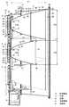
図1ないし図3に、照明装置10として投光器を示す。この照明装置10は、灯体11、この灯体11を支持する支持体12、および灯体11(光源)に電源を供給するための図示しない電源ユニットを備えている。 1 to 3 show a floodlight as thelighting device 10. Thelighting device 10 includes alamp body 11, asupport body 12 that supports thelamp body 11, and a power supply unit (not shown) for supplying power to the lamp body 11 (light source).

そして、灯体11は、本体15、この本体15の後側に配設される光源体16、本体15の前側に配設される光制御体17を備えている。 Thelamp body 11 includes amain body 15, alight source body 16 arranged on the rear side of themain body 15, and anoptical control body 17 arranged on the front side of themain body 15.

本体15は、例えば金属材料によって、前後に開口する環状に形成されている。本体15の下部には、電源ユニットからの給電ケーブルが配線される配線ボックス部19が設けられている。 Themain body 15 is formed of an annular shape that opens back and forth, for example, by a metal material. At the bottom of themain body 15, awiring box portion 19 to which a power supply cable from a power supply unit is wired is provided.

また、光源体16は、複数の光源ユニット21、およびこれら光源ユニット21を一体に取り付けた取付板22を備えており、取付板22によって本体15の後側に取り付けられている。 Further, thelight source body 16 includes a plurality oflight source units 21 and amounting plate 22 to which theselight source units 21 are integrally attached, and is attached to the rear side of themain body 15 by themounting plate 22.

光源体16の各光源ユニット21は、光源23、およびこの光源23を取り付けた放熱器24を備えている。 Eachlight source unit 21 of thelight source body 16 includes alight source 23 and aradiator 24 to which thelight source 23 is attached.

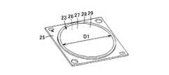
光源23は、図4に示すように、COB(Chip On Board)モジュールによって構成されている。光源(COBモジュール)23は、基板25、この基板25に実装された複数の発光素子(LED)26、およびこれら発光素子26を覆う蛍光体層27を備えている。基板25上には発光素子26の実装領域の周囲に円環状の枠状部28が設けられ、この枠状部28の内側に蛍光体層27が充填されている。蛍光体層27の表面が光を発光する発光部の発光面29であり、この発光面29は円形で所定の直径D1に形成されている。また、図1に示すように、光源23は、光源ホルダ30に保持され、絶縁性を有する熱伝導シート31を介して放熱器24の前面に取り付けられている。光源ホルダ30の中央には、光源23の発光面29に対向するとともに前方へ向けて拡開する円形の光源開口32が形成されている。 As shown in FIG. 4, thelight source 23 is composed of a COB (Chip On Board) module. The light source (COB module) 23 includes asubstrate 25, a plurality of light emitting elements (LEDs) 26 mounted on thesubstrate 25, and aphosphor layer 27 covering thelight emitting elements 26. An annular frame-shaped portion 28 is provided on thesubstrate 25 around the mounting region of thelight emitting element 26, and thephosphor layer 27 is filled inside the frame-shaped portion 28. The surface of thephosphor layer 27 is alight emitting surface 29 of a light emitting portion that emits light, and thelight emitting surface 29 is circular and has a predetermined diameter D1. Further, as shown in FIG. 1, thelight source 23 is held by thelight source holder 30 and is attached to the front surface of theradiator 24 via a heatconductive sheet 31 having an insulating property. At the center of thelight source holder 30, a circular light source opening 32 that faces thelight emitting surface 29 of thelight source 23 and expands forward is formed.

放熱器24は、例えば金属材料で形成されている。放熱器24は、平板状の放熱ベース33、およびこの放熱ベース33の背面から突出された複数の放熱フィン34を備えている。放熱ベース33の前面に光源23が取り付けられている。放熱フィン34は上下方向に沿って配設されており、放熱フィン34間に上下方向に空気が流通する間隙が設けられている。 Theradiator 24 is made of, for example, a metal material. Theradiator 24 includes a flatheat dissipation base 33 and a plurality of heat dissipation fins 34 protruding from the back surface of theheat dissipation base 33. Alight source 23 is attached to the front surface of theheat dissipation base 33. Theheat radiating fins 34 are arranged along the vertical direction, and a gap through which air flows in the vertical direction is provided between the heat radiating fins 34.

光源体16の取付板22は、各光源ユニット21の取付位置に対応して光源23が挿通される挿通孔35が形成されている。そして、各光源ユニット21の放熱器24が取付板22の後側に取り付けられている。 Themounting plate 22 of thelight source body 16 is formed with aninsertion hole 35 into which thelight source 23 is inserted, corresponding to the mounting position of eachlight source unit 21. Aradiator 24 of eachlight source unit 21 is attached to the rear side of theattachment plate 22.

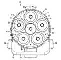
そして、本実施形態では、6つの光源23が用いられ、5つの光源23が灯体11の周辺域に周方向に沿って等間隔に配設され、1つの光源23が灯体11の中央域に配設されている。そして、これら光源23は、同一構成のものが用いられ、つまり、発光面29の大きさ(直径D1)が同じものが用いられている。なお、光源23であるCOBモジュールにおいては、発光面29の直径D1が大きいほど発光効率が高い特性を有するため、発光面29の直径D1が大きいものを用いることが好ましい。 Then, in the present embodiment, sixlight sources 23 are used, fivelight sources 23 are arranged at equal intervals along the circumferential direction in the peripheral area of thelamp body 11, and onelight source 23 is in the central region of thelamp body 11. It is arranged in. As theselight sources 23, those having the same configuration are used, that is, those having the same size (diameter D1) of thelight emitting surface 29 are used. In the COB module which is thelight source 23, the larger the diameter D1 of thelight emitting surface 29, the higher the luminous efficiency. Therefore, it is preferable to use the one having a large diameter D1 of thelight emitting surface 29.

また、光制御体17は、光制御部37、この光制御部37を収容するケース38、およびこのケース38の前面を覆う透光カバー39を備えている。 Further, theoptical control body 17 includes anoptical control unit 37, acase 38 accommodating theoptical control unit 37, and atranslucent cover 39 covering the front surface of thecase 38.

光制御部37は、光源ユニット21の光源23の1つずつに対応して配光制御に用いられる複数の反射体41、およびこれら反射体41を一体に支持して本体15に取り付ける反射体ホルダ42を備えている。 Thelight control unit 37 includes a plurality ofreflectors 41 used for light distribution control corresponding to each of thelight sources 23 of thelight source unit 21, and a reflector holder that integrally supports thesereflectors 41 and attaches them to themain body 15. It has 42.

光制御部37の反射体41は、例えば金属材料で形成されている。反射体41は、前後に開口する円筒状で、光軸方向(発光面29の中心から垂直方向に出る光の方向を光軸方向という)へ向けて拡開する放物面形状に形成されている。反射体41の後端側には光源23の発光面29に対向して光が入射する入射開口43が形成され、反射体41の前端側には光を出射する出射開口44が形成されている。 Thereflector 41 of thelight control unit 37 is made of, for example, a metal material. Thereflector 41 has a cylindrical shape that opens back and forth, and is formed in a parabolic shape that expands in the direction of the optical axis (the direction of light emitted in the vertical direction from the center of thelight emitting surface 29 is called the optical axis direction). There is. An incident opening 43 for light incident on thelight emitting surface 29 of thelight source 23 is formed on the rear end side of thereflector 41, and anexit opening 44 for emitting light is formed on the front end side of thereflector 41. ..

反射体41の内面には、光軸方向へ向けて拡開する放物面によって構成される反射面45が形成されている。この反射面45には、高屈折率膜(TiO2)と低屈折率膜(SiO2)とが積層された増反射膜46が形成されている。増反射膜46は、可視光の90%以上(好ましくは94%以上)を反射する高い反射効率を有している。A reflectingsurface 45 formed of a paraboloid that expands in the direction of the optical axis is formed on the inner surface of thereflector 41. On thereflective surface 45, anantireflection film 46 in which ahigh refractive index film (TiO 2 ) and a low refractive index film (SiO2) are laminated is formed. Theantireflection film 46 has a high reflection efficiency of reflecting 90% or more (preferably 94% or more) of visible light.

反射体41には、光軸方向の長さが異なる少なくとも2種類の反射体41が用いられている。本実施形態では、光軸方向の長さL1が長く、狭角配光の反射体(以下、長反射体という)41aと、光軸方向の長さL2が短く、長反射体41aよりも広角配光の反射体(以下、短反射体という)41bとの2種類が用いられている。 As thereflector 41, at least two types ofreflectors 41 having different lengths in the optical axis direction are used. In the present embodiment, the length L1 in the optical axis direction is long and the narrow angle light distribution reflector (hereinafter referred to as long reflector) 41a and the length L2 in the optical axis direction are short and the angle is wider than that of thelong reflector 41a. Two types of light distribution reflectors (hereinafter referred to as short reflectors) 41b are used.

長反射体41aは、入射開口43の入射開口径をD2a、出射開口44の出射開口径をD3aとすると、入射開口径D2aは発光面29の直径D1よりも大きく、出射開口径D3aは入射開口径D2aよりも大きい関係にある。 Assuming that the incident aperture diameter of theincident aperture 43 is D2a and the emission aperture diameter of theexit aperture 44 is D3a, the incident aperture diameter D2a is larger than the diameter D1 of thelight emitting surface 29, and the emission aperture diameter D3a is the incident aperture. The relationship is larger than the caliber D2a.

短反射体41bは、入射開口43の入射開口径をD2b、出射開口44の出射開口径をD3bとすると、入射開口径D2bは発光面29の直径D1よりも大きく、出射開口径D3bは入射開口径D2aよりも大きい関係にある。 Assuming that the incident aperture diameter of theincident aperture 43 is D2b and the emission aperture diameter of theexit aperture 44 is D3b, the incident aperture diameter D2b is larger than the diameter D1 of thelight emitting surface 29, and the emission aperture diameter D3b is the incident aperture. The relationship is larger than the caliber D2a.

長反射体41aの入射開口径D2aは短反射体41bの入射開口径D2bよりも大きく、長反射体41aの出射開口径D3aは短反射体41bの出射開口径D3bよりも大きい関係にある。すなわち、長反射体41aは、短反射体41bよりも全体的に径(開口径)が大きくなっている。 The incident aperture diameter D2a of thelong reflector 41a is larger than the incident aperture diameter D2b of theshort reflector 41b, and the exit aperture diameter D3a of thelong reflector 41a is larger than the exit aperture diameter D3b of theshort reflector 41b. That is, thelong reflector 41a has a larger diameter (opening diameter) as a whole than theshort reflector 41b.

長反射体41aは、入射開口43を有する後側の入射側反射体47と出射開口44を有する前側の出射側反射体48とに2分割され、これらを一体的に組み合わせて構成されている。なお、長反射体41aは、2分割せず、一体に形成されていてもよい。 Thelong reflector 41a is divided into two, a rearincident side reflector 47 having anincident opening 43 and a front emittingside reflector 48 having anexit opening 44, and these are integrally combined. Thelong reflector 41a may be integrally formed without being divided into two.

そして、各反射体41は各光源23の前方にそれぞれ配設されている。本実施形態では、灯体11の周辺域に配設される5つの光源23の前方に5つの長反射体41aがそれぞれ配設され、灯体11の中央域に配設される1つの光源23の前方に1つの短反射体41bが配設されている。 Eachreflector 41 is arranged in front of eachlight source 23. In the present embodiment, fivelong reflectors 41a are arranged in front of the fivelight sources 23 arranged in the peripheral region of thelamp body 11, and onelight source 23 arranged in the central region of thelamp body 11 is provided. Oneshort reflector 41b is arranged in front of the.

光制御体17のケース38は、例えば金属材料で、前後に開口するとともに後側から前側に向かって拡開する円筒状に形成されており、後端側が本体15の前面に取り付けられている。ケース38の前端側に、円形の照射開口50が形成されている。そして、ケース38内に複数の反射体41が収容されている。 Thecase 38 of theoptical controller 17 is made of, for example, a metal material and is formed in a cylindrical shape that opens back and forth and expands from the rear side to the front side, and the rear end side is attached to the front surface of themain body 15. Acircular irradiation opening 50 is formed on the front end side of thecase 38. A plurality ofreflectors 41 are housed in thecase 38.

光制御体17の透光カバー39は、例えば透明なガラスで、円板状に形成されている。そして、透光カバー39の周辺部がシール材52を介してケース38の前端に配置され、ケース38の前端をかしめることにより、透光カバー39がケース38の前端に固定されている。 Thetranslucent cover 39 of theoptical control body 17 is, for example, transparent glass and is formed in a disk shape. Then, the peripheral portion of thetranslucent cover 39 is arranged at the front end of thecase 38 via the sealingmaterial 52, and thetranslucent cover 39 is fixed to the front end of thecase 38 by crimping the front end of thecase 38.

また、支持体12は、灯体11を回動可能に支持し、例えば構造物などの被設置部に灯体11を設置する。支持体12は、設置部54、およびこの設置部54の両側から折曲された一対のアーム部55を備えている。設置部54は、造営物などにボルトなどによって固定される。アーム部55の先端は本体15の両側から突設されている軸部材に回動可能に連結されており、軸部材を中心として本体15を含む灯体11を回動可能に支持する。アーム部55には、アーム部55に対して灯体11を締め付け固定するためのハンドル56が配設されている。そして、ハンドル56を緩めることにより、灯体11がアーム部55に対して回動可能となり、灯体11からの光照射方向を調整することができる。 Further, thesupport body 12 rotatably supports thelamp body 11, and thelamp body 11 is installed in an installed portion such as a structure. Thesupport 12 includes aninstallation portion 54 and a pair ofarm portions 55 bent from both sides of theinstallation portion 54. Theinstallation unit 54 is fixed to a structure or the like with bolts or the like. The tip of thearm portion 55 is rotatably connected to a shaft member projecting from both sides of themain body 15, and rotatably supports thelamp body 11 including themain body 15 around the shaft member. Thearm portion 55 is provided with ahandle 56 for tightening and fixing thelamp body 11 to thearm portion 55. Then, by loosening thehandle 56, thelamp body 11 can rotate with respect to thearm portion 55, and the light irradiation direction from thelamp body 11 can be adjusted.

そして、このように構成された照明装置10において、電源ユニットから各光源23に点灯電源が供給されると、各光源23が発光し、各光源23の発光面29から出射する光が反射体41の内側に入射し、各反射体41によって配光が制御された光が透光カバー39を透過して照明領域に照射される。 Then, in thelighting device 10 configured in this way, when lighting power is supplied from the power supply unit to eachlight source 23, eachlight source 23 emits light, and the light emitted from thelight emitting surface 29 of eachlight source 23 is thereflector 41. The light incident on the inside of the light source and whose light distribution is controlled by eachreflector 41 passes through thelight transmissive cover 39 and irradiates the illumination area.

複数の反射体41のうち、長反射体41aでは光軸方向の長さL1が長いために狭角配光の光に制御し、短反射体41bでは光軸方向の長さL2が短いために長反射体41aよりも広角配光の光に制御する。 Of the plurality ofreflectors 41, thelong reflector 41a has a long length L1 in the optical axis direction, so that the light is controlled to have a narrow angle distribution, and theshort reflector 41b has a short length L2 in the optical axis direction. It controls the light with a wider angle distribution than thelong reflector 41a.

そのため、複数の長反射体41aで狭角配光に制御された光によって中心光度を確保することができるとともに、短反射体41bで広角配光に制御された光によって周辺光度を確保することができる。そして、レンズ等を用いず、反射体41のみによって配光を制御することにより、照明領域への照明率を向上できる。 Therefore, the central luminous intensity can be secured by the light controlled by the narrow-angle light distribution by the plurality oflong reflectors 41a, and the peripheral luminous intensity can be secured by the light controlled by the wide-angle light distribution by theshort reflector 41b. it can. Then, by controlling the light distribution only by thereflector 41 without using a lens or the like, the illumination rate to the illumination region can be improved.

また、光源23に用いられるCOBモジュールにおいては、発光面29の直径D1が大きいほど発光効率が高い特性を有するため、照明装置10の器具効率を高めるには、発光面29の直径D1が大きいものを用いることが好ましい。しかし、発光面29の直径D1が大きくなると、配光角が広くなりやすい。 Further, in the COB module used for thelight source 23, the larger the diameter D1 of thelight emitting surface 29 is, the higher the luminous efficiency is. Therefore, in order to improve the appliance efficiency of thelighting device 10, the diameter D1 of thelight emitting surface 29 is large. Is preferably used. However, as the diameter D1 of thelight emitting surface 29 increases, the light distribution angle tends to increase.

配光角を狭くするためにレンズを用いた投光器などもあるが、レンズの表面が光ることで、照明対象とする照明領域以外への漏れ光が多くなり、照明領域への照明率(光源23の全光束のうち照明領域に到達する光束の割合)が低下してしまう。 There are also floodlights that use a lens to narrow the light distribution angle, but when the surface of the lens shines, more light leaks to areas other than the illumination area to be illuminated, and the illumination rate to the illumination area (light source 23). The ratio of the luminous flux that reaches the illumination area to the total luminous flux of

漏れ光が少なく、照明領域への照明率を高めるには、レンズを用いず、反射体41のみを用いることが好ましいが、配光角を狭くするには開口径が大きい反射体41を用いる必要がある。 It is preferable to use only thereflector 41 without using a lens in order to reduce the leakage light and increase the illumination rate to the illumination area, but it is necessary to use thereflector 41 having a large opening diameter in order to narrow the light distribution angle. There is.

本実施形態の照明装置10では、光軸方向の長さL1が長い長反射体41aは出射開口44の開口径が大きく、光軸方向の長さL2が短い短反射体41bは出射開口44の開口径が小さい構成となっている。そして、発光面29の直径D1が大きい光源23と開口径が大きい出射開口44の長反射体41aとを組み合わせて用いることにより、配光角を狭くすることができるうえに、器具効率(光源23の全光束のうち器具外に放射される光束の割合)が高く、照明領域への照明率を高くすることができる。 In thelighting device 10 of the present embodiment, thelong reflector 41a having a long length L1 in the optical axis has a large opening diameter of theexit opening 44, and theshort reflector 41b having a short length L2 in the optical axis has anexit opening 44. It has a small opening diameter. Then, by using thelight source 23 having a large diameter D1 of thelight emitting surface 29 and thelong reflector 41a of theexit aperture 44 having a large aperture diameter in combination, the light distribution angle can be narrowed and the instrument efficiency (light source 23) can be narrowed. The ratio of the luminous flux radiated to the outside of the fixture is high, and the illumination rate to the illumination area can be increased.

仮に、灯体11内に配置される全ての反射体41について長反射体41aを用いた場合、つまり、灯体11内の中央域に配置される反射体41にも長反射体41aを用いた場合、灯体11の外径を大きくする必要があり、照明装置10が大形化してしまう。また、灯体11の外径が大きくなるのを抑制するために、灯体11内の中央域には光源23および反射体41を配置しない場合、照明装置10に必要な光束を確保することができない場合がある。 Assuming that thelong reflector 41a is used for all thereflectors 41 arranged in thelamp 11, that is, thelong reflector 41a is also used for thereflector 41 arranged in the central region in thelamp 11. In this case, it is necessary to increase the outer diameter of thelamp body 11, and thelighting device 10 becomes large. Further, in order to suppress an increase in the outer diameter of thelamp body 11, if thelight source 23 and thereflector 41 are not arranged in the central region inside thelamp body 11, it is possible to secure the luminous flux required for thelighting device 10. It may not be possible.

本実施形態の照明装置10では、灯体11内の中央域に光源23および出射開口44の開口径の小さい短反射体41bを配置することにより、灯体11の外径が大きくなるのを抑制しながら、照明装置10に必要な光束を確保することができる。 In thelighting device 10 of the present embodiment, by arranging thelight source 23 and theshort reflector 41b having a small opening diameter of theexit opening 44 in the central region of thelamp body 11, the outer diameter of thelamp body 11 is suppressed from becoming large. At the same time, the light flux required for thelighting device 10 can be secured.

そして、本実施形態の照明装置10によれば、軸方向の長さが異なる2種類の反射体41を用いることにより、つまり狭角配光の長反射体41aおよび広角配光の短反射体41bを用いることにより、中心光度および周辺光度を確保することができる。 Then, according to theillumination device 10 of the present embodiment, by using two types ofreflectors 41 having different axial lengths, that is, along reflector 41a having a narrow angle light distribution and ashort reflector 41b having a wide angle light distribution. By using, the central luminous intensity and the peripheral luminous intensity can be secured.

さらに、光軸方向の長さL1が長い長反射体41aは出射開口44の開口径が大きく、光軸方向の長さL2が短い短反射体41bは出射開口44の開口径が小さい構成となるため、出射開口44の開口径が異なる2種類の反射体41を用いることになり、灯体11の大形化を抑制しかつ光束を確保しながら、照明領域への照明率を向上できる。 Further, thelong reflector 41a having a long length L1 in the optical axis has a large opening diameter of theexit opening 44, and theshort reflector 41b having a short length L2 in the optical axis has a small opening diameter of theexit opening 44. Therefore, two types ofreflectors 41 having different aperture diameters of theexit openings 44 are used, and the illumination rate to the illumination region can be improved while suppressing the enlargement of thelamp body 11 and securing the luminous flux.

また、灯体11内の長反射体41aの数が短反射体41bの数よりも多いことにより、狭角配光の照明装置10を提供できる。 Further, since the number of thelong reflectors 41a in thelamp 11 is larger than the number of theshort reflectors 41b, theillumination device 10 having a narrow angle light distribution can be provided.

また、灯体11内の周辺域に複数の長反射体41aを配設し、中央域に短反射体41bを配設することにより、限られた大きさの灯体11内に、複数の長反射体41aおよび短反射体41bを効率よく有効に配置することができる。つまり、灯体11の周辺域に配設される複数の長反射体41aの間にできるデットスペースを有効利用して、短反射体41bを配設することができる。 Further, by arranging a plurality oflong reflectors 41a in the peripheral region in thelamp body 11 and arranging theshort reflector 41b in the central region, a plurality of lengths are arranged in thelamp body 11 having a limited size. Thereflector 41a and theshort reflector 41b can be arranged efficiently and effectively. That is, theshort reflector 41b can be arranged by effectively utilizing the dead space created between the plurality oflong reflectors 41a arranged in the peripheral area of thelamp body 11.

しかも、灯体11内の周辺域に複数の長反射体41aを配設し、中央域に短反射体41bを配設することにより、短反射体41bによる配光角が長反射体41aによる配光角よりも広くても、軸対称の配光形状とすることができる。 Moreover, by arranging a plurality oflong reflectors 41a in the peripheral region inside thelamp 11 and arranging theshort reflectors 41b in the central region, the light distribution angle by theshort reflectors 41b is arranged by thelong reflectors 41a. Even if it is wider than the light angle, it can have an axially symmetric light distribution shape.

また、灯体11内の周辺域の光源23のみを点灯して狭角配光としたり、灯体11の中央域の光源23のみを点灯して広角配光としたり、1つの照明装置10で配光を切り換えることができる。 Further, only thelight source 23 in the peripheral area inside thelamp 11 is turned on for a narrow-angle light distribution, or only thelight source 23 in the central area of thelamp 11 is turned on for a wide-angle light distribution. The light distribution can be switched.

また、灯体11の複数の光源23には、発光面29の大きさが同じ構成のもの、つまり同一の光源23を用いることにより、光源23の共通化を図り、照明装置10の製造性を向上することができる。 Further, by using thelight sources 23 having the same size of thelight emitting surface 29 as the plurality oflight sources 23 of thelamp body 11, that is, the samelight sources 23 are used, thelight sources 23 can be made common and theluminosity device 10 can be manufactured easily. Can be improved.

また、反射体41の反射面45には、高屈折膜と低屈折膜とが積層された反射効率の高い増反射膜46が形成されているため、照明装置10の器具効率が高くなるとともに、配光の広がりが少なく、配光角を狭くすることができる。 Further, since theantireflection film 46 having a high reflection efficiency in which a high refraction film and a low refraction film are laminated is formed on thereflection surface 45 of thereflector 41, the equipment efficiency of thelighting device 10 is increased and the efficiency of the fixture is increased. The spread of the light distribution is small, and the light distribution angle can be narrowed.

また、反射体41は、金属材料で形成されているため、光源23の光エネルギーが大きくても、劣化を防止することができる。 Further, since thereflector 41 is made of a metal material, deterioration can be prevented even if the light energy of thelight source 23 is large.

なお、灯体11の周辺域に5つの長反射体41aを配設し、中央域に1つの短反射体41bを配設することで、灯体11内を効率よく有効に利用して長反射体41aを配設することができるが、照明装置10の出力の種類に応じて、例えば、周辺域に6つ以上あるいは4つ以下の長反射体41aを配設してもよい。 By arranging fivelong reflectors 41a in the peripheral region of thelamp 11 and oneshort reflector 41b in the central region, the inside of thelamp 11 can be efficiently and effectively used for long reflection. Although thebody 41a can be arranged, for example, six or more or four or lesslong reflectors 41a may be arranged in the peripheral area depending on the type of output of thelighting device 10.

また、灯体11内の周辺域にも、短反射体41bを1つまたは複数配設してもよい。この場合、灯体11内の周辺域に長反射体41aと短反射体41bとを1つおきに配設してもよいし、灯体11内の周辺域を所定の領域毎に分けて配設してもよい。 Further, one or a plurality ofshort reflectors 41b may be arranged in the peripheral area in thelamp body 11. In this case, thelong reflector 41a and theshort reflector 41b may be arranged every other in the peripheral area in thelamp 11, or the peripheral area in thelamp 11 may be divided into predetermined areas. It may be installed.

また、灯体11内の周辺域に複数の短反射体41bのみを配設し、中央域に長反射体41aを配設してもよい。この場合、照明装置10の全体的な配光を広角配光としながら、中心光度も確保できる。 Further, only a plurality ofshort reflectors 41b may be arranged in the peripheral region in thelamp body 11, and thelong reflector 41a may be arranged in the central region. In this case, the central luminous intensity can be secured while the overall light distribution of thelighting device 10 is a wide-angle light distribution.

また、軸方向の長さが異なる反射体41の種類は、2種類に限らず、3種類以上の異なる長さでもよい。そして、複数種類の反射体41を組み合わせることにより、配光を任意に設定したり、各反射体41を灯体11内に効率よく配置することが可能となる。 Further, the types ofreflectors 41 having different axial lengths are not limited to two types, and three or more types having different lengths may be used. Then, by combining a plurality of types ofreflectors 41, it is possible to arbitrarily set the light distribution and efficiently arrange eachreflector 41 in thelamp body 11.

また、複数の光源23には、異なる色温度の光を放出する光源23を用いてもよい。この場合、長反射体41aには高い色温度の光源23を組み合わせ、短反射体41bには低い色温度の光源23を組み合わせたり、あるいはその逆に組み合わせてもよい。 Further, as the plurality oflight sources 23,light sources 23 that emit light having different color temperatures may be used. In this case, thelong reflector 41a may be combined with thelight source 23 having a high color temperature, and theshort reflector 41b may be combined with thelight source 23 having a low color temperature, or vice versa.

また、短反射体41bの反射面45に入射せずに出射開口44から直接出射される光源23の直接光は、長反射体41aに遮られることなく、外部に出射されることが好ましい。この場合、短反射体41bは、光軸方向の長さ、開口径、長反射体41aとの位置関係等の設定により、直接光が長反射体41aに遮られないように構成すればよい。このように構成すれば、外部に取り出される光が増加し、照明率を向上できる。 Further, it is preferable that the direct light of thelight source 23, which is directly emitted from theexit opening 44 without being incident on the reflectingsurface 45 of theshort reflector 41b, is emitted to the outside without being blocked by thelong reflector 41a. In this case, theshort reflector 41b may be configured so that direct light is not blocked by thelong reflector 41a by setting the length in the optical axis direction, the aperture diameter, the positional relationship with thelong reflector 41a, and the like. With this configuration, the amount of light taken out to the outside increases, and the lighting rate can be improved.

本発明のいくつかの実施形態を説明したが、これらの実施形態は、例として提示したものであり、発明の範囲を限定することは意図していない。これら新規な実施形態は、その他の様々な形態で実施されることが可能であり、発明の要旨を逸脱しない範囲で、種々の省略、置き換え、変更を行うことができる。これら実施形態やその変形は、発明の範囲や要旨に含まれるとともに、特許請求の範囲に記載された発明とその均等の範囲に含まれる。 Although some embodiments of the present invention have been described, these embodiments are presented as examples and are not intended to limit the scope of the invention. These novel embodiments can be implemented in various other embodiments, and various omissions, replacements, and changes can be made without departing from the gist of the invention. These embodiments and modifications thereof are included in the scope and gist of the invention, and are also included in the scope of the invention described in the claims and the equivalent scope thereof.

10 照明装置
11 灯体
23 光源
37 光制御部
41a長反射体
41b短反射体
10 Lighting equipment
11 lamp body
23 Light source
37 Optical control unit
41along reflector
41bShort reflector

Claims (1)

Translated fromJapanese
灯体と;
前記灯体の周辺域に複数配設されているとともに中心域に1つ配設される複数の光源と;
それぞれ円筒状で光軸方向へ向けて拡開するとともに光軸方向の長さが異なる少なくとも長反射体と短反射体を有し、光軸方向の長さが長い前記長反射体が前記灯体の周辺域の前記光源に対向され、光軸方向の長さが短い前記短反射体が前記灯体の中心域の前記光源に対向されており、前記短反射体は前記長反射体よりも配光角度が広い光制御部と;
を具備することを特徴とする照明装置
With a lamp;
With a plurality of light sources arranged in the peripheral area of the lamp bodyand one in the central area;
The long reflector, which is cylindrical and expands in the optical axis direction and has at least along reflector and a short reflector having different lengths in the optical axis direction and has along length in the optical axis direction, is the lamp body. The short reflector facing the light source in the peripheral region of the lamp and having a short length in the optical axis direction faces the light source in the central region of the lamp body, and the short reflector is arranged more than the long reflector. With an optical control unit with a wide optical angle;
A lighting device characterized by comprising.
JP2017004417A2017-01-132017-01-13 Lighting deviceActiveJP6849942B2 (en)

Priority Applications (1)

Application NumberPriority DateFiling DateTitle
JP2017004417AJP6849942B2 (en)2017-01-132017-01-13 Lighting device

Applications Claiming Priority (1)

Application NumberPriority DateFiling DateTitle
JP2017004417AJP6849942B2 (en)2017-01-132017-01-13 Lighting device

Publications (2)

Publication NumberPublication Date
JP2018113228A JP2018113228A (en)2018-07-19
JP6849942B2true JP6849942B2 (en)2021-03-31

Family

ID=62911280

Family Applications (1)

Application NumberTitlePriority DateFiling Date
JP2017004417AActiveJP6849942B2 (en)2017-01-132017-01-13 Lighting device

Country Status (1)

CountryLink
JP (1)JP6849942B2 (en)

Families Citing this family (1)

* Cited by examiner, † Cited by third party
Publication numberPriority datePublication dateAssigneeTitle
JP7396003B2 (en)*2019-12-042023-12-12三菱電機株式会社 lighting equipment

Family Cites Families (3)

* Cited by examiner, † Cited by third party
Publication numberPriority datePublication dateAssigneeTitle
JPS4836383Y1 (en)*1969-11-081973-10-31
JP3787148B1 (en)*2005-09-062006-06-21株式会社未来 Lighting unit and lighting device
JP6179760B2 (en)*2013-04-012017-08-16東芝ライテック株式会社 lighting equipment

Also Published As

Publication numberPublication date
JP2018113228A (en)2018-07-19

Similar Documents

PublicationPublication DateTitle
JP6539665B2 (en) Sports lighting equipment
CN101725852A (en)Lighting apparatus
JP2011508372A5 (en)
JP2016504723A (en) Flat lighting equipment
JP2008078015A (en) lighting equipment
JP2014086159A (en)Lighting device
JP2015062159A (en) Light emitting device
JP6624550B2 (en) lighting equipment
JP6425066B2 (en) lighting equipment
JP5505623B2 (en) lighting equipment
JP6849942B2 (en) Lighting device
JP6094618B2 (en) lamp
JP6102864B2 (en) lamp
JP5800164B2 (en) lighting equipment
CN213712678U (en)LED module, LED module combination and lamp
JP6721862B2 (en) Lighting equipment
US20120224368A1 (en)Led lamp with high brightness and without overlapping
JP6892627B2 (en) Lighting device
JP2016146300A (en)Light source device with socket
JP6560582B2 (en) Louver and floodlight
JP2014093129A (en)Light-emitting unit and luminaire
JP6366017B2 (en) lighting equipment
JP5457576B1 (en) Lighting device
JP5558619B1 (en) Lighting device
JP5673705B2 (en) Lighting device

Legal Events

DateCodeTitleDescription
A621Written request for application examination

Free format text:JAPANESE INTERMEDIATE CODE: A621

Effective date:20190911

A977Report on retrieval

Free format text:JAPANESE INTERMEDIATE CODE: A971007

Effective date:20200525

A131Notification of reasons for refusal

Free format text:JAPANESE INTERMEDIATE CODE: A131

Effective date:20200610

A521Written amendment

Free format text:JAPANESE INTERMEDIATE CODE: A523

Effective date:20200807

TRDDDecision of grant or rejection written
A01Written decision to grant a patent or to grant a registration (utility model)

Free format text:JAPANESE INTERMEDIATE CODE: A01

Effective date:20210203

A61First payment of annual fees (during grant procedure)

Free format text:JAPANESE INTERMEDIATE CODE: A61

Effective date:20210216

R151Written notification of patent or utility model registration

Ref document number:6849942

Country of ref document:JP

Free format text:JAPANESE INTERMEDIATE CODE: R151


[8]ページ先頭

©2009-2025 Movatter.jp