JP6848903B2 - Component insertion device, component insertion method, and program - Google Patents
Component insertion device, component insertion method, and programDownload PDFInfo
- Publication number
- JP6848903B2 JP6848903B2JP2018042074AJP2018042074AJP6848903B2JP 6848903 B2JP6848903 B2JP 6848903B2JP 2018042074 AJP2018042074 AJP 2018042074AJP 2018042074 AJP2018042074 AJP 2018042074AJP 6848903 B2JP6848903 B2JP 6848903B2
- Authority
- JP
- Japan
- Prior art keywords
- slot
- fpc
- claws
- pair
- component
- Prior art date
- Legal status (The legal status is an assumption and is not a legal conclusion. Google has not performed a legal analysis and makes no representation as to the accuracy of the status listed.)
- Expired - Fee Related
Links
- 238000003780insertionMethods0.000titleclaimsdescription53
- 230000037431insertionEffects0.000titleclaimsdescription53
- 238000012966insertion methodMethods0.000titleclaimsdescription19
- 210000000078clawAnatomy0.000claimsdescription84
- 238000000034methodMethods0.000claimsdescription29
- 238000012545processingMethods0.000claimsdescription17
- 238000006243chemical reactionMethods0.000claimsdescription7
- 238000003384imaging methodMethods0.000claimsdescription4
- 238000010586diagramMethods0.000description11
- 238000012986modificationMethods0.000description4
- 230000004048modificationEffects0.000description4
- 230000008030eliminationEffects0.000description2
- 238000003379elimination reactionMethods0.000description2
- 239000004033plasticSubstances0.000description2
- 239000004065semiconductorSubstances0.000description2
- 238000013519translationMethods0.000description2
- RYGMFSIKBFXOCR-UHFFFAOYSA-NCopperChemical compound[Cu]RYGMFSIKBFXOCR-UHFFFAOYSA-N0.000description1
- 239000004593EpoxySubstances0.000description1
- 239000004642PolyimideSubstances0.000description1
- 239000000853adhesiveSubstances0.000description1
- 230000001070adhesive effectEffects0.000description1
- 239000012790adhesive layerSubstances0.000description1
- 238000013459approachMethods0.000description1
- 230000005540biological transmissionEffects0.000description1
- 238000004891communicationMethods0.000description1
- 239000004020conductorSubstances0.000description1
- 239000011889copper foilSubstances0.000description1
- 238000002474experimental methodMethods0.000description1
- 239000011888foilSubstances0.000description1
- 239000000463materialSubstances0.000description1
- 229920001721polyimidePolymers0.000description1
- 229920001187thermosetting polymerPolymers0.000description1
Images


Classifications
- B—PERFORMING OPERATIONS; TRANSPORTING
- B25—HAND TOOLS; PORTABLE POWER-DRIVEN TOOLS; MANIPULATORS
- B25J—MANIPULATORS; CHAMBERS PROVIDED WITH MANIPULATION DEVICES
- B25J9/00—Programme-controlled manipulators
- B25J9/16—Programme controls
- B25J9/1679—Programme controls characterised by the tasks executed
- B25J9/1687—Assembly, peg and hole, palletising, straight line, weaving pattern movement
- B—PERFORMING OPERATIONS; TRANSPORTING
- B25—HAND TOOLS; PORTABLE POWER-DRIVEN TOOLS; MANIPULATORS
- B25J—MANIPULATORS; CHAMBERS PROVIDED WITH MANIPULATION DEVICES
- B25J13/00—Controls for manipulators
- B—PERFORMING OPERATIONS; TRANSPORTING
- B25—HAND TOOLS; PORTABLE POWER-DRIVEN TOOLS; MANIPULATORS
- B25J—MANIPULATORS; CHAMBERS PROVIDED WITH MANIPULATION DEVICES
- B25J9/00—Programme-controlled manipulators
- B25J9/16—Programme controls
- B25J9/1612—Programme controls characterised by the hand, wrist, grip control
- B—PERFORMING OPERATIONS; TRANSPORTING
- B25—HAND TOOLS; PORTABLE POWER-DRIVEN TOOLS; MANIPULATORS
- B25J—MANIPULATORS; CHAMBERS PROVIDED WITH MANIPULATION DEVICES
- B25J9/00—Programme-controlled manipulators
- B25J9/16—Programme controls
- B25J9/1628—Programme controls characterised by the control loop
- B25J9/1633—Programme controls characterised by the control loop compliant, force, torque control, e.g. combined with position control
- H—ELECTRICITY
- H05—ELECTRIC TECHNIQUES NOT OTHERWISE PROVIDED FOR
- H05K—PRINTED CIRCUITS; CASINGS OR CONSTRUCTIONAL DETAILS OF ELECTRIC APPARATUS; MANUFACTURE OF ASSEMBLAGES OF ELECTRICAL COMPONENTS
- H05K13/00—Apparatus or processes specially adapted for manufacturing or adjusting assemblages of electric components
- H05K13/04—Mounting of components, e.g. of leadless components
- H05K13/0404—Pick-and-place heads or apparatus, e.g. with jaws
- H—ELECTRICITY
- H05—ELECTRIC TECHNIQUES NOT OTHERWISE PROVIDED FOR
- H05K—PRINTED CIRCUITS; CASINGS OR CONSTRUCTIONAL DETAILS OF ELECTRIC APPARATUS; MANUFACTURE OF ASSEMBLAGES OF ELECTRICAL COMPONENTS
- H05K3/00—Apparatus or processes for manufacturing printed circuits
- H05K3/36—Assembling printed circuits with other printed circuits
- H05K3/361—Assembling flexible printed circuits with other printed circuits
- H05K3/365—Assembling flexible printed circuits with other printed circuits by abutting, i.e. without alloying process
- G—PHYSICS
- G05—CONTROLLING; REGULATING
- G05B—CONTROL OR REGULATING SYSTEMS IN GENERAL; FUNCTIONAL ELEMENTS OF SUCH SYSTEMS; MONITORING OR TESTING ARRANGEMENTS FOR SUCH SYSTEMS OR ELEMENTS
- G05B2219/00—Program-control systems
- G05B2219/30—Nc systems
- G05B2219/40—Robotics, robotics mapping to robotics vision
- G05B2219/40028—Insert flexible rod, beam into hole
- H—ELECTRICITY
- H01—ELECTRIC ELEMENTS
- H01R—ELECTRICALLY-CONDUCTIVE CONNECTIONS; STRUCTURAL ASSOCIATIONS OF A PLURALITY OF MUTUALLY-INSULATED ELECTRICAL CONNECTING ELEMENTS; COUPLING DEVICES; CURRENT COLLECTORS
- H01R12/00—Structural associations of a plurality of mutually-insulated electrical connecting elements, specially adapted for printed circuits, e.g. printed circuit boards [PCB], flat or ribbon cables, or like generally planar structures, e.g. terminal strips, terminal blocks; Coupling devices specially adapted for printed circuits, flat or ribbon cables, or like generally planar structures; Terminals specially adapted for contact with, or insertion into, printed circuits, flat or ribbon cables, or like generally planar structures
- H01R12/70—Coupling devices
- H01R12/77—Coupling devices for flexible printed circuits, flat or ribbon cables or like structures
- H—ELECTRICITY
- H01—ELECTRIC ELEMENTS
- H01R—ELECTRICALLY-CONDUCTIVE CONNECTIONS; STRUCTURAL ASSOCIATIONS OF A PLURALITY OF MUTUALLY-INSULATED ELECTRICAL CONNECTING ELEMENTS; COUPLING DEVICES; CURRENT COLLECTORS
- H01R43/00—Apparatus or processes specially adapted for manufacturing, assembling, maintaining, or repairing of line connectors or current collectors or for joining electric conductors
Landscapes
- Engineering & Computer Science (AREA)
- Robotics (AREA)
- Mechanical Engineering (AREA)
- Manufacturing & Machinery (AREA)
- Microelectronics & Electronic Packaging (AREA)
- Health & Medical Sciences (AREA)
- General Health & Medical Sciences (AREA)
- Orthopedic Medicine & Surgery (AREA)
- Metallurgy (AREA)
- Manipulator (AREA)
- Automatic Assembly (AREA)
Description
Translated fromJapaneseこの発明は部品挿入装置および部品挿入方法に関し、より詳しくは、細長いスロットを有する受け部に、上記スロットに嵌合する平板状の形状をもつワーク部品を挿入する部品挿入装置および部品挿入方法に関する。また、この発明は、そのような部品挿入方法をコンピュータに実行させるためのプログラムに関する。 The present invention relates to a component insertion device and a component insertion method, and more particularly to a component insertion device and a component insertion method for inserting a work component having a flat plate shape fitted into the slot into a receiving portion having an elongated slot. The present invention also relates to a program for causing a computer to execute such a component insertion method.
細長いスロットを有する受け部に、上記スロットに嵌合する平板状の形状をもつワーク部品を挿入する典型的な場合として、例えば特許文献1(特開平10−27659号公報)に開示されているように、細長いストレート形状の隙間(スロット)を有するFPC(Flexible Printed Circuit;フレキシブル配線板)用コネクタに、平板状の形状をもつFPCをスライド挿入する場合がある。 As a typical case of inserting a work component having a flat plate shape to be fitted into the slot into a receiving portion having an elongated slot, for example, as disclosed in Patent Document 1 (Japanese Unexamined Patent Publication No. 10-27659). In some cases, an FPC having a flat plate shape is slid into a connector for an FPC (Flexible Printed Circuit) having an elongated straight-shaped gap (slot).
従来より、このようなFPC用コネクタにFPCをスライド挿入する工程(FPC挿入工程)を、例えばロボットを用いて自動的に行う試みがなされている。 Conventionally, attempts have been made to automatically perform a step of sliding and inserting an FPC into such an FPC connector (FPC insertion step) using, for example, a robot.
しかしながら、FPC挿入工程については、次のような理由によって、機械化・自動化が進んでいないのが実情である。
− 第1に、接触探索が困難であることが挙げられる。具体的には、ロボットに力覚センサを設けて、FPCをFPC用コネクタのスロットの周りに接触させ、FPCが受ける接触反力に基づいてスロットの位置を探索しようとしても、接触の仕方によってはFPC自体が曲がって大きく塑性変形してしまうことがある。このため、接触反力に基づいてスロットの位置を探索することが困難である。なお、FPCが大きく塑性変形すると、廃棄する必要が生ずる。
− 第2に、タクト時間が長くかかることが挙げられる。具体的には、FPCの破損(塑性変形を含む。)を回避するためには、コンプライアンス制御によってFPCをゆっくり押し込む必要がある。このとき、押し込み速度を遅く、かつ、噛みつき解消動作(FPCが挿入口に引っ掛かる現象を、FPCを細かく振動させて解消する動作)を遅く設定する必要がある。結果として、1枚のFPCを挿入するのに、例えば約150秒間程度かかってしまう。However, the fact is that the FPC insertion process has not been mechanized and automated for the following reasons.
-First, it is difficult to search for contact. Specifically, even if the robot is provided with a force sensor, the FPC is brought into contact with the slot of the FPC connector, and the position of the slot is searched based on the contact reaction force received by the FPC, depending on the contact method. The FPC itself may bend and undergo large plastic deformation. Therefore, it is difficult to search for the position of the slot based on the contact reaction force. If the FPC is greatly plastically deformed, it will be necessary to dispose of it.
-Second, it takes a long time to tact. Specifically, in order to avoid damage to the FPC (including plastic deformation), it is necessary to slowly push the FPC by compliance control. At this time, it is necessary to set the pushing speed to be slow and the bite elimination operation (the operation to eliminate the phenomenon that the FPC is caught in the insertion slot by vibrating the FPC finely). As a result, it takes about 150 seconds, for example, to insert one FPC.
そこで、この発明の課題は、細長いストレート形状のスロットを有する受け部に、上記スロットに嵌合する平板状の形状をもつワーク部品であって比較的柔らかいものを、短時間で自動的に挿入できる部品挿入装置および部品挿入方法を提供することにある。また、この発明の課題は、そのような部品挿入方法をコンピュータに実行させるためのプログラムを提供することにある。 Therefore, an object of the present invention is that a relatively soft work part having a flat plate shape fitted to the slot can be automatically inserted into a receiving portion having an elongated straight slot in a short time. To provide a component insertion device and a component insertion method. Another object of the present invention is to provide a program for causing a computer to execute such a component insertion method.
上記課題を解決するため、この開示の部品挿入装置は、
細長いストレート形状のスロットを有する受け部に、上記スロットに嵌合する平板状の形状をもつワーク部品の特定部分を挿入する部品挿入装置であって、
ロボットと、
このロボットの動作を制御する制御部とを備え、
上記ロボットは、
上記特定部分を外部へ突出させた態様で上記ワーク部品を挟持することが可能な一対の爪を有するグリッパと、
上記受け部の上記スロットの周りから上記ワーク部品が受ける接触反力を、上記グリッパを介して検出可能な力覚センサと
を有し、
上記一対の爪は、互いに接近して上記ワーク部品を挟持するとき、上記ワーク部品の少なくとも上記特定部分を厚さ方向に湾曲または屈曲させる特定形状をもち、
上記制御部は、
上記一対の爪を互いに接近させて、上記ワーク部品を、上記スロットの短手方向寸法の範囲内で上記特定部分を厚さ方向に湾曲または屈曲させながら、上記特定部分を外部へ突出させた態様で挟持する処理を行う挟持処理部と、
上記ロボットによって、上記受け部の上記スロットに、上記一対の爪によって挟持された上記ワーク部品の上記特定部分を、この特定部分がなす先端面に垂直な挿入方向に沿って、上記力覚センサの出力に基づいてコンプライアンス制御によって挿入する処理を行う挿入処理部と
を備えたことを特徴とする。In order to solve the above problems, the component insertion device of this disclosure is
A component insertion device that inserts a specific portion of a work component having a flat plate shape that fits into the slot into a receiving portion having an elongated straight slot.
With a robot
It is equipped with a control unit that controls the operation of this robot.
The above robot
A gripper having a pair of claws capable of sandwiching the work part in a manner in which the specific portion is projected to the outside, and
It has a force sensor that can detect the contact reaction force received by the work component from around the slot of the receiving portion via the gripper.
The pair of claws have a specific shape that bends or bends at least the specific portion of the work part in the thickness direction when the work part is sandwiched in close proximity to each other.
The control unit
A mode in which the pair of claws are brought close to each other, and the work part is projected outward while the specific portion is curved or bent in the thickness direction within the range of the lateral dimension of the slot. The pinching processing unit that performs the pinching process and
By the robot, the specific portion of the work part sandwiched by the pair of claws in the slot of the receiving portion is inserted into the slot of the receiving portion along the insertion direction perpendicular to the tip surface formed by the specific portion of the force sensor. It is characterized by having an insertion processing unit that performs insertion processing by compliance control based on the output.
本明細書で、ワーク部品の「特定部分」とは、上記スロットまたは孔に挿入される部分に相当する。したがって、その「特定部分」が上記スロットまたは孔に嵌合する平板状の形状をもてば足りる。「特定部分」とは、端部に限られず、他の部分を指していてもよい。 As used herein, the "specific portion" of a workpiece corresponds to a portion inserted into the slot or hole. Therefore, it suffices to have a flat plate shape in which the "specific portion" fits into the slot or hole. The “specific part” is not limited to the end portion, and may refer to another portion.
また、ワーク部品の特定部分としては、実際上、平板状の形状のままでは、力覚センサによって接触反力を測定することが困難な、比較的柔らかいものが対象となる。その理由は、仮にワーク部品が平板状の形状のままであっても力覚センサによって接触反力を測定できるようなものであれば、上記ワーク部品の特定部分を厚さ方向に湾曲または屈曲させる必要が無く、上記受け部の上記スロットに上記ワーク部品の特定部分を平板状の形状のままコンプライアンス制御によって挿入すればよいからである。 Further, as the specific part of the work part, a relatively soft part, which is difficult to measure the contact reaction force by the force sensor, is targeted in practice with the flat plate shape. The reason is that even if the work part remains in a flat plate shape, if the contact reaction force can be measured by the force sensor, the specific part of the work part is curved or bent in the thickness direction. This is because there is no need to insert the specific portion of the work component into the slot of the receiving portion by compliance control while maintaining the flat plate shape.
また、上記スロットの「短手方向寸法」は、上記ワーク部品の厚さ寸法に対して、予め定められたクリアランス寸法だけ広く設定されている。 Further, the "short direction dimension" of the slot is set wider by a predetermined clearance dimension with respect to the thickness dimension of the work part.
また、上記特定部分がなす「先端面」とは、上記特定部分の先端に相当する面を指す。この先端面は、上記ワーク部品が平板状の形状(本来の形状)にある場合も、上記特定部分が厚さ方向に湾曲または屈曲された場合も、実質的に或る平面をなしていると考えられる。 Further, the "tip surface" formed by the specific portion refers to a surface corresponding to the tip of the specific portion. The tip surface is substantially flat regardless of whether the workpiece has a flat plate shape (original shape) or the specific portion is curved or bent in the thickness direction. Conceivable.
この開示の部品挿入装置では、上記ロボットのグリッパが有する一対の爪は、互いに接近して上記ワーク部品を挟持するとき、上記ワーク部品の少なくとも上記特定部分を厚さ方向に湾曲または屈曲させる特定形状をもっている。上記制御部の挟持処理部は、上記一対の爪を互いに接近させて、上記ワーク部品を、上記スロットの短手方向寸法の範囲内で上記特定部分を厚さ方向に湾曲または屈曲させながら、上記特定部分を外部(グリッパの爪の外部)へ突出させた態様で挟持する処理を行う。これにより、上記特定部分がなす先端面に垂直な挿入方向に関して、上記ワーク部品の強度(実質的な硬さ)が増す。次に、挿入処理部は、上記ロボットによって、上記受け部の上記スロットに、上記一対の爪によって挟持された上記ワーク部品の上記特定部分を、この特定部分がなす先端面に垂直な挿入方向に沿って、上記力覚センサの出力に基づいてコンプライアンス制御によって挿入する処理を行う。このとき、コンプライアンス制御ではあるけれども、上記ワーク部品の上記特定部分の強度が増しているので、比較的短時間(例えば、約20秒間〜30秒間程度)で挿入を完了できる。また、上記ワーク部品の上記特定部分の強度が増しているので、上記ワーク部品が大きく塑性変形するのを防止できる。したがって、この部品挿入装置によれば、細長いストレート形状のスロットを有する受け部に、上記スロットに嵌合する平板状の形状(本来の形状)をもつワーク部品であって比較的柔らかいものを、短時間で自動的に挿入できる。 In the component inserting device of the present disclosure, when the pair of claws of the gripper of the robot are close to each other to sandwich the workpiece, at least the specific portion of the workpiece is curved or bent in the thickness direction. Have. The pinching processing unit of the control unit brings the pair of claws close to each other, and bends or bends the specific portion in the thickness direction of the work component within the range of the lateral dimension of the slot. A process of sandwiching a specific part in a manner of projecting to the outside (outside the gripper's claw) is performed. As a result, the strength (substantial hardness) of the workpiece increases with respect to the insertion direction perpendicular to the tip surface formed by the specific portion. Next, the insertion processing unit inserts the specific portion of the work part sandwiched by the pair of claws into the slot of the receiving portion by the robot in the insertion direction perpendicular to the tip surface formed by the specific portion. Along with this, a process of inserting by compliance control is performed based on the output of the force sensor. At this time, although it is compliance control, the strength of the specific portion of the work component is increased, so that the insertion can be completed in a relatively short time (for example, about 20 to 30 seconds). Further, since the strength of the specific portion of the work part is increased, it is possible to prevent the work part from being significantly plastically deformed. Therefore, according to this component insertion device, a relatively soft work component having a flat plate shape (original shape) that fits into the slot is shortened to a receiving portion having an elongated straight slot. Can be inserted automatically in time.
一実施形態の部品挿入装置では、
上記一対の爪によって挟持された上記ワーク部品の上記厚さ方向に湾曲または屈曲した上記先端面を撮像する撮像部を備え、
上記制御部は、上記撮像部によって得られた上記先端面の画像に基づいて、上記ワーク部品の上記先端面における実効的厚さ寸法を求める寸法取得部を有し、
上記挟持処理部は、上記先端面における上記実効的厚さ寸法に基づいて、この実効的厚さ寸法が上記スロットの短手方向寸法未満になるように、上記一対の爪の間の距離を可変して設定することを特徴とする。In the component insertion device of one embodiment,
An image pickup unit for imaging the tip surface of the work component sandwiched by the pair of claws, which is curved or bent in the thickness direction, is provided.
The control unit has a dimension acquisition unit that obtains an effective thickness dimension of the work component on the front end surface based on the image of the tip surface obtained by the image pickup unit.
Based on the effective thickness dimension on the tip surface, the pinching processing unit changes the distance between the pair of claws so that the effective thickness dimension is less than the lateral dimension of the slot. It is characterized by setting.
本明細書で、上記先端面における「実効的厚さ寸法」とは、厚さ方向に関して、上記先端面における一方の輪郭線に対する外接線と、他方の輪郭線に対する外接線とが作る距離を意味している。 In the present specification, the "effective thickness dimension" on the tip surface means the distance formed by the circumscribed line with respect to one contour line on the tip surface and the circumscribed line with respect to the other contour line in the thickness direction. are doing.
この一実施形態の部品挿入装置では、撮像部は、上記一対の爪によって挟持された上記ワーク部品の上記厚さ方向に湾曲または屈曲した上記先端面を撮像する。上記制御部の寸法取得部は、上記ワーク部品の上記先端面における実効的厚さ寸法を求める。上記挟持処理部は、上記先端面における上記実効的厚さ寸法に基づいて、この実効的厚さ寸法が上記スロットの短手方向寸法未満になるように、上記一対の爪の間の距離を可変して設定する。これにより、上記ワーク部品の上記先端面(したがって、上記端部)が上記スロットに挿入され得る寸法になる。 In the component insertion device of this embodiment, the imaging unit images the tip surface of the work component sandwiched by the pair of claws, which is curved or bent in the thickness direction. The dimension acquisition unit of the control unit obtains an effective thickness dimension of the work component on the tip surface. Based on the effective thickness dimension on the tip surface, the pinching processing unit changes the distance between the pair of claws so that the effective thickness dimension is less than the lateral dimension of the slot. And set. As a result, the tip surface (and therefore the end) of the work component has a size that allows it to be inserted into the slot.
別の局面では、この開示の部品挿入方法は、
上記部品挿入装置によって、細長いストレート形状のスロットを有する受け部に、上記スロットに嵌合する平板状の形状をもつワーク部品の特定部分を挿入する部品挿入方法であって、
上記一対の爪を互いに接近させて、上記ワーク部品を、上記スロットの短手方向寸法の範囲内で上記特定部分を厚さ方向に湾曲または屈曲させながら、上記特定部分を外部へ突出させた態様で挟持する処理を行った後、
上記ロボットによって、上記受け部の上記スロットに、上記一対の爪によって挟持された上記ワーク部品の上記特定部分を、この特定部分がなす先端面に垂直な挿入方向に沿って、上記力覚センサの出力に基づいてコンプライアンス制御によって挿入する処理を行う
ことを特徴とする。In another aspect, the component insertion method of this disclosure
A component insertion method in which a specific portion of a work component having a flat plate shape to be fitted into the slot is inserted into a receiving portion having an elongated straight slot by the component insertion device.
A mode in which the pair of claws are brought close to each other, and the work part is projected outward while the specific portion is curved or bent in the thickness direction within the range of the lateral dimension of the slot. After performing the process of sandwiching with
By the robot, the specific portion of the work part sandwiched by the pair of claws in the slot of the receiving portion is inserted into the slot of the receiving portion along the insertion direction perpendicular to the tip surface formed by the specific portion of the force sensor. It is characterized in that the process of inserting is performed by compliance control based on the output.
この開示の部品挿入方法によれば、細長いストレート形状のスロットを有する受け部に、上記スロットに嵌合する平板状の形状(本来の形状)をもつワーク部品であって比較的柔らかいものを、短時間で自動的に挿入できる。 According to the component insertion method of the present disclosure, a relatively soft work component having a flat plate shape (original shape) that fits into the slot is shortened to a receiving portion having an elongated straight slot. Can be inserted automatically in time.
さらに別の局面では、この開示のプログラムは、上記部品挿入方法をコンピュータに実行させるためのプログラムである。 In yet another aspect, the program of this disclosure is a program for causing a computer to execute the above-mentioned component insertion method.
この開示のプログラムをコンピュータに実行させることによって、上記部品挿入方法を実施することができる。 The above-mentioned component insertion method can be carried out by causing a computer to execute the program of this disclosure.
以上より明らかなように、この開示の部品挿入装置および部品挿入方法によれば、細長いストレート形状のスロットを有する受け部に、上記スロットに嵌合する平板状の形状をもつワーク部品であって比較的柔らかいものを、短時間で自動的に挿入することができる。また、この開示のプログラムをコンピュータに実行させることによって、上記部品挿入方法を実施することができる。 As is clear from the above, according to the component insertion device and the component insertion method of the present disclosure, a work component having a flat plate shape that fits into the slot in a receiving portion having an elongated straight slot is compared. A soft object can be automatically inserted in a short time. Further, the above-mentioned component insertion method can be carried out by causing a computer to execute the program of this disclosure.
以下、この発明の実施の形態を、図面を参照しながら詳細に説明する。 Hereinafter, embodiments of the present invention will be described in detail with reference to the drawings.
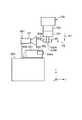
図1(A)は、この発明の一実施形態の部品挿入装置1の外観を模式的に示している。この部品挿入装置1は、この例では組立台800の近傍に配置されたロボット100と、このロボット100の動作を制御するコントローラ10と、撮像部としてのカメラ20とを備えている。 FIG. 1A schematically shows the appearance of the
この例では、組立台800は、ロボット100の可動範囲内に設置されている。この組立台800上に、仕掛品600として、受け部としてのFPC(Flexible Printed Circuit;フレキシブル配線板)用コネクタ602を有する回路基板601を搭載したものが載置されている(仕掛品600は、図示しない要素によって組立台800上に固定されていてもよい。)。カメラ20は、アーム付きスタンド801によって、FPC用コネクタ602の上方に、視野をロボット100へ向けた姿勢で保持されている。図1(C)に示すように、FPC用コネクタ602は、細長いストレート形状のスロット602sを有している。部品挿入装置1は、このようなFPC用コネクタ602のスロット602sに、ワーク部品としての矩形の平板状の形状をもつFPC90の特定部分としての端部90eを、自動的に挿入するための装置である。スロット602sの開口の長手方向寸法SL1、短手方向寸法SL2は、それぞれFPC90の端部90eの長手方向寸法FP1(この例では、3cm)、短手方向寸法FP2(この例では、0.20mm)よりも一定のクリアランス寸法だけ大きく、この例ではSL1=3.2cm、SL2=2mmに設定されている。スロット602sの深さ(つまり、FPC90の挿入深さ)は、この例では5mmに設定されている。なお、スロット602sの短手方向寸法SL2は、スロット602s内で深さが深くなるにつれて次第に小さく(狭く)なっていてもよい。 In this example, the assembly table 800 is installed within the movable range of the
ロボット100は、この例ではグリッパ101を有する6軸(6制御軸)多関節ロボットからなっている。このロボット100は、並進の自由度を表す3軸であるx(x軸の位置)、y(y軸の位置)およびz(z軸の位置)と、回転の自由度を表す3軸であるyaw(ヨー角)、pitch(ピッチ角)およびroll(ロール角)とを有している。図1(B)は、図1(A)におけるグリッパ101近傍部分(2点鎖線Bで囲まれた部分)を示している。この図1(B)に示すように、グリッパ101は、この例ではFPC90を挟持することが可能な一対の爪102A,102Bを有している。一対の爪102A,102Bは、グリッパ101の先端面101bから外部へ細長く突出している。なお、図1(B)において爪102Bは、爪102Aの奥側に隠れて配置されている。この例では、グリッパ101は、サーボ制御により、一対の爪102A,102Bを互いに接近する向き又はその逆に互いに互いに離間する向きにスライドさせて、一対の爪102A,102Bの間の間隔を調整することができる(また、挟持力も調整することができる。)。グリッパ101の爪102A,102BがFPC90をその中央部90cで把持すると、FPC90の端部90eは外部へ突出した態様になる。 In this example, the
この例では、矩形の平板状のFPC90の寸法は、全長7cm、幅3cm(=FP1)、厚さ0.20mm(=FP2)として設定されている。グリッパ101の爪102A,102BによってFPC90の中央部90cが把持された状態では、FPC90の端部90eは、グリッパ101の爪102A,102Bの外部(この例では、側方)へ約3cm程度突出した態様になるとともに、後述するように厚さ方向に湾曲(または屈曲)する。 In this example, the dimensions of the rectangular flat plate-shaped
FPC90は、公知のものであり、ポリイミド等の比較的柔らかい基材の上に、接着層(例えばエポキシ系熱硬化型接着剤)を介して導体箔(銅箔など)を設けて構成されている。 The
また、ロボット100のグリッパ101近傍の部位には、力覚センサ103が搭載されている。この力覚センサ103は、後述の処理(図6のステップS4)の際に、FPC用コネクタ602のスロット602sの周りからFPC90が受ける接触反力を、グリッパ101を介して検出することができる。 Further, a
図2(A−1)は上記グリッパ101が有する一対の爪102A,102Bを斜めから見たところ示している。この例では、一方の爪102Aは、四角柱状の主部102mと、この主部102mから他方の爪102Bへ向かって半円柱状(この例では、半径2.0cm)に突起した特定形状としての凸部102pとを有している。凸部102pは、この主部102mの長手方向中央部に配置され、主部102mの長手方向に交差する向きに延在している。他方の爪102Bは、一方の爪102Aの主部102mに対して平行に延在する四角柱状の主部102nと、この主部102nのうち一方の爪102Aの凸部102pに対応する部位に形成され、凸部102pを受け得るように半円筒状に窪んだ特定形状としての凹部102qとを有している。一対の爪102A,102Bの間にFPC90が配され、一対の爪102A,102Bの主部102m,102n間の間隔Dが矢印E1,E2で示すように互いに接近されると、凸部102pと凹部102qとの間にFPC90の中央部90cが挟まれて、図2(A−2)に示すように、FPC90は端部90eを含めて厚さ方向Eに円弧状に湾曲する。これにより、端部90eをなす先端面90pにおける実効的厚さ寸法FP2effが大きくなる。ここで、実効的厚さ寸法FP2effとは、厚さ方向Eに関して、先端面90pにおける一方の輪郭線(この例では図2(A−2)における右側の輪郭線)90p1に対する外接線cu1と、他方の輪郭線(この例では図2(A−2)における左側の輪郭線)90p2に対する外接線cu2とが作る距離を意味している。この例では、図2(A−3)に示すように、FPC用コネクタ602のスロット602sに、一対の爪102A,102Bによって挟持されたFPC90の端部90eを、この端部90eがなす先端面90pに垂直な挿入方向P4に沿って挿入することを予定している(詳しくは、後述する。)。 FIG. 2 (A-1) shows a pair of
図3(A−1)、図3(A−2)、図3(A−3)は、図2(A−1)に示した一対の爪102A,102Bの主部102m,102n間の間隔Dを、この例では2.0cm、1.0cm、0.0cmというように順次可変して設定したときの態様を示している。図3(B−1)、図3(B−2)、図3(B−3)に示すように、一対の爪102A,102Bの主部102m,102n間の間隔Dに応じて、湾曲されたFPC90の先端面90pにおける実効的厚さ寸法FP2effは、この例では、0.25mm、0.5mm、1.0mmというように順次変化している。一対の爪102A,102Bの主部102m,102n間の間隔D(単位cm)と湾曲されたFPC90の先端面90pにおける実効的厚さ寸法FP2eff(単位mm)との間の関係は、図4に示すように、2次曲線Cで近似され得る。この2次曲線Cは、本発明者らによる実験によって求められたもので、この例では、
FP2eff = 0.125D2 − 0.625D + 1 …(Eq.1)
として求められている。このように、一対の爪102A,102Bの主部102m,102n間の間隔Dを可変して設定することによって、FPC90の先端面90pにおける実効的厚さ寸法FP2effを調節することができる。3 (A-1), 3 (A-2), and 3 (A-3) show the distance between the
FP2eff = 0.125D 2 - 0.625D + 1 ... (Eq.1)
Is required as. In this way, the effective thickness dimension FP2eff on the
図5に示すように、コントローラ10は、この例では、入力部11、記憶部12、および、ロボット制御部30を備えている。 As shown in FIG. 5, the
入力部11は、この例ではティーチングペンダントからなっている。この例では、入力部11は、特に、ユーザが処理開始命令を入力するために用いられる。 The
記憶部12は、この例では不揮発性半導体メモリからなっている。この例では、記憶部12は、特に、後述の処理(図6のステップS2)の際に、カメラ20によって撮像された画像を記憶する。 The
ロボット制御部30は、この例では、記憶部12に格納されたロボット制御プログラムに従って動作するプロセッサによって構成されている。このロボット制御部30は、6軸のロボット100を、その軸数と同数の6要素からなる制御情報CVを用いて制御する。制御情報CVは、並進の自由度を表す3要素であるx(x軸の位置)、y(y軸の位置)およびz(z軸の位置)と、回転の自由度を表す3要素であるyaw(ヨー角の値)、pitch(ピッチ角の値)およびroll(ロール角の値)とを含む。通常の位置制御では、制御情報CVの各要素は、それぞれ一定周期で逐次値が更新され、それによって、それぞれロボット100の各軸が駆動される。 In this example, the
また、この例では、ロボット制御部30は、ロボット100について、力覚センサ103の出力信号FSを受けて、コンプライアンス制御(ロボット先端の位置と姿勢、およびロボット先端にかかる力を用いて、ロボットにやわらかい動きをさせる制御)を行うことができる。コンプライアンス制御では、例えば、力覚センサ103において検出された挿入方向(例えば−y方向)に交差(直交)する方向(x方向及びz方向)の力成分が小さくなるようにロボット100の動作がフィードバック制御される。 Further, in this example, the
コントローラ10とロボット100との間の、制御情報CV、力覚センサ103の出力信号FSの送受信は、図1(A)中に示したケーブル10Cを介して行われる。 The transmission / reception of the control information CV and the output signal FS of the
また、この例では、ロボット制御部30は、無線通信によって又は図示しないケーブルを介して、カメラ20が撮像した画像を表す信号MSを受信する。 Further, in this example, the
カメラ20は、後述の処理(図6のステップS2)の際に、一対の爪102A,102Bによって挟持されたFPC90の厚さ方向Eに湾曲または屈曲した先端面90pを撮像し、得られた画像を表す信号MSをロボット制御部30へ出力する。 The
図6は、上述の部品挿入装置1が行う一実施形態の部品挿入方法の動作フローを示している。次に、図7A〜図7D(図1(A)における+x方向から見たところ)を併せて参照しながら、FPC用コネクタ602のスロット602sにFPC90の端部90eを自動的に挿入する処理について説明する。 FIG. 6 shows an operation flow of the component insertion method of one embodiment performed by the
図7Aに示すように、予め、組立台800上に、FPC用コネクタ602を含む仕掛品600を載置しておくものとする。カメラ20は、アーム付きスタンド801によって、FPC用コネクタ602の上方に、視野を+y方向のロボット100へ向けた姿勢で保持されている。このとき、この例では、ロボット100のグリッパ101は、組立台800から離れた位置に存在している。 As shown in FIG. 7A, it is assumed that the work-in-
ユーザが入力部11によって処理開始命令を入力すると、まず、図6のステップS1に示すように、コントローラ10のロボット制御部30は挟持処理部として働いて、ロボット100のグリッパ101の一対の爪102A,102Bを互いに接近させて、図2(A−2)に示したように、FPC90を、端部90eを含めて厚さ方向Eに湾曲(この例では、円弧状に湾曲)させながら、図7Aに示すように、端部90eを外部へ突出させた態様で挟持する。これにより、端部90eがなす先端面90pに垂直な挿入方向(この例では、−y方向)に関して、FPC90の強度(実質的な硬さ)が増す。この図7Aの状態では、FPC90の端部90eは、ロボット100を基準として−y方向を向いている。 When the user inputs a processing start command through the
次に、ロボット制御部30は、図7B中に矢印P1,P2で示すようにロボット100を動かして、一対の爪102A,102Bによって挟持されたFPC90を、端部90e(つまり、先端面90p)が−y方向に向いた姿勢のまま、カメラ20へ接近させる。この状態で、図6のステップS2に示すように、カメラ20は、一対の爪102A,102Bによって挟持されたFPC90の厚さ方向Eに湾曲した先端面90p(図2(A−2)参照)を撮像し、得られた画像を表す信号MSをロボット制御部30へ出力する。ロボット制御部30は、カメラ20によって撮像された画像(FPC90の厚さ方向Eに湾曲または屈曲した先端面90pを表す画像)を記憶部12に一旦記憶させる。 Next, the
次に、図6のステップS3に示すように、ロボット制御部30は寸法取得部として働いて、カメラ20によって得られた先端面90pの画像に基づいて、FPC90の先端面90pにおける実効的厚さ寸法FP2effを求める。具体的には、例えば図2(A−2)中に示すように、FPC90の先端面90pの画像上で、厚さ方向Eに関して、一方の輪郭線90p1に対する外接線cu1と、他方の輪郭線90p2に対する外接線cu2とを設定し、それらの外接線cu1,cu2間の距離を求める。続いて、ロボット制御部30は挟持処理部として働いて、先端面90pにおける実効的厚さ寸法FP2effに基づいて、この実効的厚さ寸法FP2effがスロット602sの短手方向寸法SL2未満になるように、一対の爪102A,102Bの間の距離Dを可変して設定する。これにより、FPC90の先端面90pにおける実効的厚さ寸法FP2effが、図2(A−3)中に示すスロット602sの短手方向寸法SL2の範囲内になって、FPC90の先端面90p(したがって、端部90e)がスロット602sに挿入され得る寸法になる。 Next, as shown in step S3 of FIG. 6, the
次に、図6のステップS4に示すように、ロボット制御部30は挿入処理部として働いて、ロボット100によって、FPC用コネクタ602のスロット602sに、一対の爪102A,102Bによって挟持されたFPC90の端部90eを、この端部90eがなす先端面90pに垂直な挿入方向(この例では、−y方向)に沿って、力覚センサ103の出力に基づいてコンプライアンス制御によって挿入する処理を行う。これにより、図7C中に矢印P3,P4で示すように、FPC用コネクタ602のスロット602sにFPC90の端部90eが挿入される(なお、この例では、矢印P4は−y方向に向いている。)。このとき、コンプライアンス制御ではあるけれども、FPC90の端部90eの強度が増しているので、比較的短時間(例えば、約20秒間〜30秒間程度)で挿入を完了できる。また、FPC90の端部90eの強度が増しているので、FPC90が大きく塑性変形するのを防止できる。 Next, as shown in step S4 of FIG. 6, the
ここで、コンプライアンス制御によって挿入する処理は、具体的には、図8(A)の状態から開始して、次のような手順で行われる。まず、図8(B)中に矢印Q1で示すように、FPC用コネクタ602のスロット602sの周り(開口近傍)にFPC90の端部90e(先端面90p)を突き当てる(突き当て動作)。次に、図8(C)中に矢印Q2で示すように、FPC90の端部90eによってスロット602sの開口の位置を探る(探り動作)。スロット602sの開口の位置が見つかったら、図8(D)中に矢印Q3で示すように、FPC用コネクタ602のスロット602sの入口近傍にFPC90の端部90eを押し込む(押し込み動作)。押し込み中に、図8(E)中に記号Q4で示すように、FPC90の端部90eを細かく振動させて噛みつき(スロット602sの入口に引っ掛かる現象)を解消する(噛みつき解消動作)。このようにして、図8(F)に示すように、FPC用コネクタ602のスロット602sにFPC90の端部90eを挿入する。スロット602sに挿入されたFPC90の端部90eの形状は、スロット602sのストレート形状に沿って、本来の平板状の形状に戻る。 Here, the process of inserting by the compliance control is specifically started from the state of FIG. 8A and performed in the following procedure. First, as shown by an arrow Q1 in FIG. 8B, the
この後、ロボット100のグリッパ101の一対の爪102A,102Bは開かれて、FPC90を離す。そして、図7D中に矢印P5で示すように、ロボット100は、組立台800から離れる向き(+y方向)に後退する。 After that, the pair of
このように、この部品挿入装置1によれば、細長いストレート形状のスロット602sを有するFPC用コネクタ602に、スロット602sに嵌合する平板状の形状(本来の形状)をもつFPC90であって比較的柔らかいものを、自動的に挿入できる。 As described above, according to the
なお、グリッパ101は、挟持しているFPC90が一対の爪102A,102Bに対して位置ずれするのを防止するストッパ(図示せず)を有している。したがって、図6のステップS3で仮に一対の爪102A,102Bの間の距離Dが比較的広く設定されたとしても、スロット602sにFPC90の端部90eを挿入する処理(図6のステップS4)の際に、FPC90が一対の爪102A,102Bに対して位置ずれすることはない。 The
(変形例)
上述の例では、ロボット100のグリッパ101の一対の爪102A,102BによってFPC90の中央部90cを挟持する処理(図6のステップS1)の際に、FPC90を、端部90eを含めて厚さ方向Eに円弧状に湾曲させるものとした。しかしながら、これに限られるものではない。例えば、図2(B−1)はグリッパ101が有する一対の爪102A,102Bの変形例(符号102A′,102B′で示す。)を示している。この例では、一方の爪102A′は、四角柱状の主部102m′と、この主部102m′から側方(図2(B−1)では手前側)へ向かって円柱状(この例では、半径1.4cm)に突起した特定形状としての横棒部102rとを有している。横棒部102rは、この主部102m′の長手方向中央部に配置され、主部102m′の長手方向に交差する向きに延在している。他方の爪102B′は、一方の爪102A′の主部102m′に対して平行に延在する四角柱状の主部102n′と、この主部102n′から側方(図2(B−1)では手前側)へ向かって円柱状(この例では、半径1.4cm)に突起した特定形状としての横棒部102s1,102s2とを有している。横棒部102s1,102s2は、主部102n′のうち、高さ方向に関して一方の爪102A′の横棒部102rの最上部、最下部に対応する部位に形成され、横棒部102rに対してそれぞれ平行に延在している。一対の爪102A′,102B′の間にFPC90が配され、一対の爪102A′,102B′の主部102m′,102n′間の間隔Dが矢印E1,E2で示すように互いに接近されると、主部102m′,102n′間にFPC90の中央部90cが挟まれるとともに、横棒部102rと横棒部102s1,102s2との間にFPC90の端部90eが挟まれて、図2(B−2)に示すように、FPC90の端部90eは厚さ方向Eに波状に湾曲する。これにより、端部90eをなす先端面90pにおける実効的厚さ寸法FP2effが大きくなる。したがって、図2(B−3)に示すように、FPC用コネクタ602のスロット602sに、一対の爪102A′,102B′によって挟持されたFPC90の端部90eを、この端部90eがなす先端面90pに垂直な挿入方向P4に沿って挿入すると、既述の例と同様に、比較的短時間で挿入を完了できる。また、FPC90の端部90eの強度が増しているので、FPC90が大きく塑性変形するのを防止できる。(Modification example)
In the above example, during the process of sandwiching the
また、図2(C−1)はグリッパ101が有する一対の爪102A,102Bの別の変形例(符号102A″,102B″で示す。)を示している。この例では、一方の爪102A″は、矩形の平板状の主部102m″を有している。図2(C−1)において、この主部102m″の特定形状としての下端102tは、他方の爪102Bの下端102uよりも上方に位置している。他方の爪102B″は、一方の爪102A″の主部102m″に対して平行に延在する四角柱状の主部102n″と、この主部102n″の下端102uに形成され、一方の爪102A″の下端102tよりも下方で、一方の爪102A″の側(図2(C−1)における右側)へ向かって突起した特定形状としての突起部102vとを有している。一対の爪102A″,102B″の間にFPC90が配され、一対の爪102A″,102B″の主部102m″,102n″間の間隔Dが矢印E1,E2で示すように互いに接近されると、主部102m″,102n″間にFPC90が挟まれて、図2(C−2)に示すように、FPC90は端部90eのコーナー部90e1を含めて厚さ方向Eに屈曲する。これにより、端部90eをなす先端面90pにおける実効的厚さ寸法FP2effが大きくなる。したがって、図2(C−3)に示すように、FPC用コネクタ602のスロット602sに、一対の爪102A″,102B″によって挟持されたFPC90の端部90eを、この端部90eがなす先端面90pに垂直な挿入方向P4に沿って挿入すると、既述の例と同様に、比較的短時間で挿入を完了できる。また、FPC90の端部90eの強度が増しているので、FPC90が大きく塑性変形するのを防止できる。 Further, FIG. 2 (C-1) shows another modification (indicated by
このように、グリッパ101の一対の爪102A,102Bが有する特定形状は、スロット602sの短手方向寸法SL2の範囲内でFPC90の端部90eがなす先端面90pにおける実効的厚さ寸法FP2effを大きくできれば良く、様々な形状をとり得る。 As described above, the specific shape of the pair of
上述の例では、スロットまたは孔を有する受け部(仕掛品600に含まれたFPC用コネクタ602)が組立台800上に載置されているものとしたが、これに限られるものではない。スロットまたは孔を有する受け部は、例えばベルトコンベアによってロボット100の可動範囲内に搬送されて来て、上述の処理(図6のステップS1〜S4)の間、ロボット100に対する配置が維持されるようになっていてもよい。 In the above example, it is assumed that the receiving portion having a slot or a hole (
また、細長いストレート形状のスロットまたは孔を有する受け部と、上記スロットまたは孔に嵌合する平板状の形状をもつワーク部品との組み合わせとしては、既述のFPC用コネクタ602とFPC90との組み合わせ例に限られず、様々なものが対象となり得る。 Further, as a combination of a receiving portion having an elongated straight-shaped slot or hole and a work component having a flat plate shape fitted to the slot or hole, an example of a combination of the
上記コントローラ10のロボット制御部30は、プログラムに従って動作するプロセッサによって構成されている。また、記憶部12は、不揮発性半導体メモリなどの記憶装置によって構成されている。つまり、これらのロボット制御部30と記憶部12は、実質的にコンピュータ装置(例えば、プログラマブルロジックコントローラ(programmable logic controller;PLC)など)によって構成され得る。したがって、図6によって説明した部品挿入方法は、コンピュータに実行させるためのプログラムとして構成されるのが望ましい。また、そのプログラムは、コンピュータ読み取り可能な非一時的(non-transitory)な記録媒体に記録されるのが望ましい。その場合、記録媒体に記録されたそれらのプログラムをコンピュータ装置に読み取らせ、実行させることによって、上述の部品挿入方法を実施することができる。 The
以上の実施形態は例示であり、この発明の範囲から離れることなく様々な変形が可能である。上述した複数の実施の形態は、それぞれ単独で成立し得るものであるが、実施の形態同士の組みあわせも可能である。また、異なる実施の形態の中の種々の特徴も、それぞれ単独で成立し得るものであるが、異なる実施の形態の中の特徴同士の組みあわせも可能である。 The above embodiment is an example, and various modifications can be made without departing from the scope of the present invention. The plurality of embodiments described above can be established independently, but combinations of the embodiments are also possible. Further, although various features in different embodiments can be established independently, it is also possible to combine features in different embodiments.
1 部品挿入装置
10 コントローラ
20 カメラ
90 FPC
100 ロボット
101 グリッパ
102A,102B,102A′,102B′,102A″,102B″ 爪
103 力覚センサ
602 FPC用コネクタ
602s スロット1
100
Claims (4)
Translated fromJapaneseロボットと、
このロボットの動作を制御する制御部とを備え、
上記ロボットは、
上記特定部分を外部へ突出させた態様で上記ワーク部品を挟持することが可能な一対の爪を有するグリッパと、
上記受け部の上記スロットの周りから上記ワーク部品が受ける接触反力を、上記グリッパを介して検出可能な力覚センサと
を有し、
上記一対の爪は、互いに接近して上記ワーク部品を挟持するとき、上記ワーク部品の少なくとも上記特定部分を厚さ方向に湾曲または屈曲させる特定形状をもち、
上記制御部は、
上記一対の爪を互いに接近させて、上記ワーク部品を、上記スロットの短手方向寸法の範囲内で上記特定部分を厚さ方向に湾曲または屈曲させながら、上記特定部分を外部へ突出させた態様で挟持する処理を行う挟持処理部と、
上記ロボットによって、上記受け部の上記スロットに、上記一対の爪によって挟持された上記ワーク部品の上記特定部分を、この特定部分がなす先端面に垂直な挿入方向に沿って、上記力覚センサの出力に基づいてコンプライアンス制御によって挿入する処理を行う挿入処理部と
を備えたことを特徴とする部品挿入装置。A component insertion device that inserts a specific portion of a work component having a flat plate shape that fits into the slot into a receiving portion having an elongated straight slot.
With a robot
It is equipped with a control unit that controls the operation of this robot.
The above robot
A gripper having a pair of claws capable of sandwiching the work part in a manner in which the specific portion is projected to the outside, and
It has a force sensor that can detect the contact reaction force received by the work component from around the slot of the receiving portion via the gripper.
The pair of claws have a specific shape that bends or bends at least the specific portion of the work part in the thickness direction when the work part is sandwiched in close proximity to each other.
The control unit
A mode in which the pair of claws are brought close to each other, and the work part is projected outward while the specific portion is curved or bent in the thickness direction within the range of the lateral dimension of the slot. The pinching processing unit that performs the pinching process and
By the robot, the specific portion of the work part sandwiched by the pair of claws in the slot of the receiving portion is inserted into the slot of the receiving portion along the insertion direction perpendicular to the tip surface formed by the specific portion of the force sensor. A component insertion device including an insertion processing unit that performs insertion processing by compliance control based on an output.
上記一対の爪によって挟持された上記ワーク部品の上記厚さ方向に湾曲または屈曲した上記先端面を撮像する撮像部を備え、
上記制御部は、上記撮像部によって得られた上記先端面の画像に基づいて、上記ワーク部品の上記先端面における実効的厚さ寸法を求める寸法取得部を有し、
上記挟持処理部は、上記先端面における上記実効的厚さ寸法に基づいて、この実効的厚さ寸法が上記スロットの短手方向寸法未満になるように、上記一対の爪の間の距離を可変して設定することを特徴とする部品挿入装置。In the component insertion device according to claim 1,
An image pickup unit for imaging the tip surface of the work component sandwiched by the pair of claws, which is curved or bent in the thickness direction, is provided.
The control unit has a dimension acquisition unit that obtains an effective thickness dimension of the work component on the front end surface based on the image of the tip surface obtained by the image pickup unit.
Based on the effective thickness dimension on the tip surface, the pinching processing unit can change the distance between the pair of claws so that the effective thickness dimension is less than the lateral dimension of the slot. A component insertion device characterized in that it is set.
上記一対の爪を互いに接近させて、上記ワーク部品を、上記スロットの短手方向寸法の範囲内で上記特定部分を厚さ方向に湾曲または屈曲させながら、上記特定部分を外部へ突出させた態様で挟持する処理を行った後、
上記ロボットによって、上記受け部の上記スロットに、上記一対の爪によって挟持された上記ワーク部品の上記特定部分を、この特定部分がなす先端面に垂直な挿入方向に沿って、上記力覚センサの出力に基づいてコンプライアンス制御によって挿入する処理を行う
ことを特徴とする部品挿入方法。A component insertion method for inserting a specific portion of a work component having a flat plate shape to be fitted into the slot into a receiving portion having an elongated straight-shaped slot by the component inserting device according to claim 1.
A mode in which the pair of claws are brought close to each other, and the work part is projected outward while the specific portion is curved or bent in the thickness direction within the range of the lateral dimension of the slot. After performing the process of sandwiching with
By the robot, the specific portion of the work component sandwiched by the pair of claws in the slot of the receiving portion is inserted into the slot of the receiving portion along the insertion direction perpendicular to the tip surface formed by the specific portion of the force sensor. A component insertion method characterized in that a process of inserting by compliance control is performed based on an output.
Priority Applications (4)
| Application Number | Priority Date | Filing Date | Title |
|---|---|---|---|
| JP2018042074AJP6848903B2 (en) | 2018-03-08 | 2018-03-08 | Component insertion device, component insertion method, and program |
| CN201811492384.8ACN110248531B (en) | 2018-03-08 | 2018-12-07 | Component insertion device and component insertion method |
| US16/218,444US10967516B2 (en) | 2018-03-08 | 2018-12-12 | Component insertion device, component insertion method and program |
| EP18212669.8AEP3566825B1 (en) | 2018-03-08 | 2018-12-14 | Workpiece insertion device, workpiece insertion method and program |
Applications Claiming Priority (1)
| Application Number | Priority Date | Filing Date | Title |
|---|---|---|---|
| JP2018042074AJP6848903B2 (en) | 2018-03-08 | 2018-03-08 | Component insertion device, component insertion method, and program |
Publications (2)
| Publication Number | Publication Date |
|---|---|
| JP2019155496A JP2019155496A (en) | 2019-09-19 |
| JP6848903B2true JP6848903B2 (en) | 2021-03-24 |
Family
ID=64665667
Family Applications (1)
| Application Number | Title | Priority Date | Filing Date |
|---|---|---|---|
| JP2018042074AExpired - Fee RelatedJP6848903B2 (en) | 2018-03-08 | 2018-03-08 | Component insertion device, component insertion method, and program |
Country Status (4)
| Country | Link |
|---|---|
| US (1) | US10967516B2 (en) |
| EP (1) | EP3566825B1 (en) |
| JP (1) | JP6848903B2 (en) |
| CN (1) | CN110248531B (en) |
Families Citing this family (3)
| Publication number | Priority date | Publication date | Assignee | Title |
|---|---|---|---|---|
| CN111417299B (en)* | 2020-04-13 | 2021-03-23 | 温州职业技术学院 | Method for manufacturing circuit substrate body |
| TW202317338A (en)* | 2021-10-21 | 2023-05-01 | 日商倉敷紡績股份有限公司 | Connection method for board to board connector |
| CN116900192B (en)* | 2023-09-13 | 2023-12-05 | 万向钱潮股份公司 | Sealing device for shock absorber |
Family Cites Families (33)
| Publication number | Priority date | Publication date | Assignee | Title |
|---|---|---|---|---|
| US4132318A (en)* | 1976-12-30 | 1979-01-02 | International Business Machines Corporation | Asymmetric six-degree-of-freedom force-transducer system for a computer-controlled manipulator system |
| JPH04189495A (en)* | 1990-11-22 | 1992-07-07 | Matsushita Electric Ind Co Ltd | Method and device for positioning |
| JP3479960B2 (en) | 1996-07-10 | 2003-12-15 | 住友電装株式会社 | FPC connector |
| JPH10104796A (en)* | 1996-09-26 | 1998-04-24 | Fuji Photo Film Co Ltd | Method and device for loading photosensitive sheet material |
| JPH1186078A (en)* | 1997-09-03 | 1999-03-30 | Omron Corp | Paper sheet discriminating device |
| CN1228673A (en)* | 1998-12-28 | 1999-09-15 | 四川长虹电子集团公司 | Inserting method for horizontal component and inserting head of automatic insertion machine specially-using said method |
| JP2000283902A (en)* | 1999-03-30 | 2000-10-13 | Shimadzu Corp | Transporter for soft samples |
| US6612143B1 (en)* | 2001-04-13 | 2003-09-02 | Orametrix, Inc. | Robot and method for bending orthodontic archwires and other medical devices |
| US7181314B2 (en)* | 2003-11-24 | 2007-02-20 | Abb Research Ltd. | Industrial robot with controlled flexibility and simulated force for automated assembly |
| US7783383B2 (en)* | 2004-12-22 | 2010-08-24 | Intelligent Hospital Systems Ltd. | Automated pharmacy admixture system (APAS) |
| US7150652B1 (en)* | 2006-02-21 | 2006-12-19 | Myoungsoo Jeon | Connector having a pair of printed circuits and facing sets of contact beams |
| JP5105147B2 (en)* | 2006-08-28 | 2012-12-19 | 株式会社安川電機 | Robot and control method |
| JP4249789B2 (en)* | 2007-07-23 | 2009-04-08 | ファナック株式会社 | Flexible work assembly method |
| CN102292194B (en)* | 2009-08-21 | 2015-03-04 | 松下电器产业株式会社 | Robot arm control device and control method, assembly robot, robot arm control program, and robot arm control integrated circuit |
| US8504205B2 (en)* | 2011-03-17 | 2013-08-06 | Harris Corporation | Robotic grasping device with multi-force sensing at base of fingers |
| WO2013080500A1 (en)* | 2011-11-30 | 2013-06-06 | パナソニック株式会社 | Robot teaching device, robot device, control method for robot teaching device, and control program for robot teaching device |
| EP3007867B1 (en)* | 2013-06-11 | 2020-10-21 | OnRobot A/S | Systems and methods for sensing objects |
| JP5681271B1 (en)* | 2013-07-26 | 2015-03-04 | ファナック株式会社 | Robotic gripping device |
| CN104552322A (en)* | 2013-10-28 | 2015-04-29 | 精工爱普生株式会社 | Gripping apparatus, robot, and gripping method |
| JP2015089575A (en)* | 2013-11-05 | 2015-05-11 | セイコーエプソン株式会社 | Robot, control device, robot system and control method |
| JP6489745B2 (en)* | 2014-03-03 | 2019-03-27 | キヤノン株式会社 | ROBOT DEVICE, ROBOT DEVICE CONTROL METHOD, ARTICLE ASSEMBLY METHOD USING ROBOT DEVICE, PROGRAM, AND RECORDING MEDIUM |
| US9535522B2 (en)* | 2014-12-22 | 2017-01-03 | Lg Display Co., Ltd. | Flexible organic light emitting diode display device |
| JP6219890B2 (en)* | 2015-07-17 | 2017-10-25 | ファナック株式会社 | Automatic assembly system by robot |
| JP6693098B2 (en)* | 2015-11-26 | 2020-05-13 | セイコーエプソン株式会社 | Robots and robot systems |
| WO2017103682A2 (en)* | 2015-12-16 | 2017-06-22 | Mbl Limited | Robotic manipulation methods and systems for executing a domain-specific application in an instrumented environment with containers and electronic minimanipulation libraries |
| JP6301994B2 (en)* | 2016-04-04 | 2018-03-28 | ファナック株式会社 | Robotic gripping device |
| JP2017196705A (en)* | 2016-04-28 | 2017-11-02 | セイコーエプソン株式会社 | Robot and robot system |
| JP6915239B2 (en)* | 2016-07-22 | 2021-08-04 | セイコーエプソン株式会社 | Insertion method |
| JP2018015857A (en)* | 2016-07-29 | 2018-02-01 | セイコーエプソン株式会社 | Control device and robot |
| JP2018015853A (en)* | 2016-07-29 | 2018-02-01 | セイコーエプソン株式会社 | Robot and robot system |
| JP2018051735A (en)* | 2016-09-30 | 2018-04-05 | セイコーエプソン株式会社 | Robot control device, robot and robot system |
| CN206154336U (en)* | 2016-10-19 | 2017-05-10 | 深圳市艾励美特科技有限公司 | Absorption device |
| CN107336255B (en)* | 2017-07-12 | 2023-08-25 | 天津职业技术师范大学 | A multifunctional industrial robot gripper |
- 2018
- 2018-03-08JPJP2018042074Apatent/JP6848903B2/ennot_activeExpired - Fee Related
- 2018-12-07CNCN201811492384.8Apatent/CN110248531B/enactiveActive
- 2018-12-12USUS16/218,444patent/US10967516B2/ennot_activeExpired - Fee Related
- 2018-12-14EPEP18212669.8Apatent/EP3566825B1/ennot_activeNot-in-force
Also Published As
| Publication number | Publication date |
|---|---|
| US20190275677A1 (en) | 2019-09-12 |
| US10967516B2 (en) | 2021-04-06 |
| JP2019155496A (en) | 2019-09-19 |
| EP3566825A1 (en) | 2019-11-13 |
| CN110248531B (en) | 2020-09-29 |
| CN110248531A (en) | 2019-09-17 |
| EP3566825B1 (en) | 2021-09-01 |
Similar Documents
| Publication | Publication Date | Title |
|---|---|---|
| CN110253564B (en) | Part insertion device, part insertion method, and computer-readable recording medium | |
| JP6848903B2 (en) | Component insertion device, component insertion method, and program | |
| EP2993002B1 (en) | Robot apparatus and method for controlling robot apparatus | |
| JP6791150B2 (en) | Mounting device, mounting method, and hand mechanism | |
| US20130085604A1 (en) | Robot apparatus, robot system, and method for producing a to-be-processed material | |
| US11589489B2 (en) | Lead wire straightening device | |
| JP7167681B2 (en) | Robot system and connection method | |
| CN101352807A (en) | Flexible workpiece assembling method | |
| CN111618844B (en) | Robot system and control method | |
| CN114494420A (en) | A flexible circuit board assembly device and method | |
| TW202019643A (en) | Robot system and coupling method | |
| CN114555240A (en) | End effector and control device for end effector | |
| JP2021119024A (en) | Connection method and robot system | |
| JP6928316B2 (en) | Parts mounting machine with holding function | |
| US10813259B2 (en) | Board work machine and insertion method | |
| US10617049B2 (en) | Component mounting device and gripping members | |
| CN112518762B (en) | Transport systems, transport methods, robots | |
| CN118434541A (en) | Robot control device, robot system, and robot control program | |
| JPWO2018134912A1 (en) | Parts insertion machine | |
| US20240356294A1 (en) | Connector insertion method and inspection method | |
| CN110740631B (en) | Electronic component mounting device and electronic component mounting method | |
| JP2024158152A (en) | Inspection method and position detection method | |
| JP5579037B2 (en) | Work positioning method and apparatus |
Legal Events
| Date | Code | Title | Description |
|---|---|---|---|
| A621 | Written request for application examination | Free format text:JAPANESE INTERMEDIATE CODE: A621 Effective date:20200228 | |
| TRDD | Decision of grant or rejection written | ||
| A977 | Report on retrieval | Free format text:JAPANESE INTERMEDIATE CODE: A971007 Effective date:20210129 | |
| A01 | Written decision to grant a patent or to grant a registration (utility model) | Free format text:JAPANESE INTERMEDIATE CODE: A01 Effective date:20210202 | |
| A61 | First payment of annual fees (during grant procedure) | Free format text:JAPANESE INTERMEDIATE CODE: A61 Effective date:20210215 | |
| R150 | Certificate of patent or registration of utility model | Ref document number:6848903 Country of ref document:JP Free format text:JAPANESE INTERMEDIATE CODE: R150 | |
| LAPS | Cancellation because of no payment of annual fees |