JP6848778B2 - Power supply device - Google Patents
Power supply deviceDownload PDFInfo
- Publication number
- JP6848778B2 JP6848778B2JP2017177316AJP2017177316AJP6848778B2JP 6848778 B2JP6848778 B2JP 6848778B2JP 2017177316 AJP2017177316 AJP 2017177316AJP 2017177316 AJP2017177316 AJP 2017177316AJP 6848778 B2JP6848778 B2JP 6848778B2
- Authority
- JP
- Japan
- Prior art keywords
- power supply
- capacitor
- power
- output terminal
- capacitor unit
- Prior art date
- Legal status (The legal status is an assumption and is not a legal conclusion. Google has not performed a legal analysis and makes no representation as to the accuracy of the status listed.)
- Expired - Fee Related
Links
Images


Classifications
- H—ELECTRICITY
- H02—GENERATION; CONVERSION OR DISTRIBUTION OF ELECTRIC POWER
- H02M—APPARATUS FOR CONVERSION BETWEEN AC AND AC, BETWEEN AC AND DC, OR BETWEEN DC AND DC, AND FOR USE WITH MAINS OR SIMILAR POWER SUPPLY SYSTEMS; CONVERSION OF DC OR AC INPUT POWER INTO SURGE OUTPUT POWER; CONTROL OR REGULATION THEREOF
- H02M7/00—Conversion of AC power input into DC power output; Conversion of DC power input into AC power output
- H02M7/02—Conversion of AC power input into DC power output without possibility of reversal
- H02M7/04—Conversion of AC power input into DC power output without possibility of reversal by static converters
- H02M7/06—Conversion of AC power input into DC power output without possibility of reversal by static converters using discharge tubes without control electrode or semiconductor devices without control electrode
- H—ELECTRICITY
- H02—GENERATION; CONVERSION OR DISTRIBUTION OF ELECTRIC POWER
- H02M—APPARATUS FOR CONVERSION BETWEEN AC AND AC, BETWEEN AC AND DC, OR BETWEEN DC AND DC, AND FOR USE WITH MAINS OR SIMILAR POWER SUPPLY SYSTEMS; CONVERSION OF DC OR AC INPUT POWER INTO SURGE OUTPUT POWER; CONTROL OR REGULATION THEREOF
- H02M1/00—Details of apparatus for conversion
- H02M1/0003—Details of control, feedback or regulation circuits
- H02M1/0006—Arrangements for supplying an adequate voltage to the control circuit of converters
- H—ELECTRICITY
- H02—GENERATION; CONVERSION OR DISTRIBUTION OF ELECTRIC POWER
- H02M—APPARATUS FOR CONVERSION BETWEEN AC AND AC, BETWEEN AC AND DC, OR BETWEEN DC AND DC, AND FOR USE WITH MAINS OR SIMILAR POWER SUPPLY SYSTEMS; CONVERSION OF DC OR AC INPUT POWER INTO SURGE OUTPUT POWER; CONTROL OR REGULATION THEREOF
- H02M1/00—Details of apparatus for conversion
- H02M1/0096—Means for increasing hold-up time, i.e. the duration of time that a converter's output will remain within regulated limits following a loss of input power
- H—ELECTRICITY
- H02—GENERATION; CONVERSION OR DISTRIBUTION OF ELECTRIC POWER
- H02P—CONTROL OR REGULATION OF ELECTRIC MOTORS, ELECTRIC GENERATORS OR DYNAMO-ELECTRIC CONVERTERS; CONTROLLING TRANSFORMERS, REACTORS OR CHOKE COILS
- H02P7/00—Arrangements for regulating or controlling the speed or torque of electric DC motors
- H02P7/06—Arrangements for regulating or controlling the speed or torque of electric DC motors for regulating or controlling an individual DC dynamo-electric motor by varying field or armature current
- H02P7/18—Arrangements for regulating or controlling the speed or torque of electric DC motors for regulating or controlling an individual DC dynamo-electric motor by varying field or armature current by master control with auxiliary power
- H02P7/24—Arrangements for regulating or controlling the speed or torque of electric DC motors for regulating or controlling an individual DC dynamo-electric motor by varying field or armature current by master control with auxiliary power using discharge tubes or semiconductor devices
- H02P7/28—Arrangements for regulating or controlling the speed or torque of electric DC motors for regulating or controlling an individual DC dynamo-electric motor by varying field or armature current by master control with auxiliary power using discharge tubes or semiconductor devices using semiconductor devices
- H02P7/285—Arrangements for regulating or controlling the speed or torque of electric DC motors for regulating or controlling an individual DC dynamo-electric motor by varying field or armature current by master control with auxiliary power using discharge tubes or semiconductor devices using semiconductor devices controlling armature supply only
- H02P7/292—Arrangements for regulating or controlling the speed or torque of electric DC motors for regulating or controlling an individual DC dynamo-electric motor by varying field or armature current by master control with auxiliary power using discharge tubes or semiconductor devices using semiconductor devices controlling armature supply only using static converters, e.g. AC to DC
- H—ELECTRICITY
- H02—GENERATION; CONVERSION OR DISTRIBUTION OF ELECTRIC POWER
- H02M—APPARATUS FOR CONVERSION BETWEEN AC AND AC, BETWEEN AC AND DC, OR BETWEEN DC AND DC, AND FOR USE WITH MAINS OR SIMILAR POWER SUPPLY SYSTEMS; CONVERSION OF DC OR AC INPUT POWER INTO SURGE OUTPUT POWER; CONTROL OR REGULATION THEREOF
- H02M5/00—Conversion of AC power input into AC power output, e.g. for change of voltage, for change of frequency, for change of number of phases
- H02M5/40—Conversion of AC power input into AC power output, e.g. for change of voltage, for change of frequency, for change of number of phases with intermediate conversion into DC
- H02M5/42—Conversion of AC power input into AC power output, e.g. for change of voltage, for change of frequency, for change of number of phases with intermediate conversion into DC by static converters
- H02M5/44—Conversion of AC power input into AC power output, e.g. for change of voltage, for change of frequency, for change of number of phases with intermediate conversion into DC by static converters using discharge tubes or semiconductor devices to convert the intermediate DC into AC
- H02M5/453—Conversion of AC power input into AC power output, e.g. for change of voltage, for change of frequency, for change of number of phases with intermediate conversion into DC by static converters using discharge tubes or semiconductor devices to convert the intermediate DC into AC using devices of a triode or transistor type requiring continuous application of a control signal
- H02M5/458—Conversion of AC power input into AC power output, e.g. for change of voltage, for change of frequency, for change of number of phases with intermediate conversion into DC by static converters using discharge tubes or semiconductor devices to convert the intermediate DC into AC using devices of a triode or transistor type requiring continuous application of a control signal using semiconductor devices only
- H—ELECTRICITY
- H02—GENERATION; CONVERSION OR DISTRIBUTION OF ELECTRIC POWER
- H02P—CONTROL OR REGULATION OF ELECTRIC MOTORS, ELECTRIC GENERATORS OR DYNAMO-ELECTRIC CONVERTERS; CONTROLLING TRANSFORMERS, REACTORS OR CHOKE COILS
- H02P2201/00—Indexing scheme relating to controlling arrangements characterised by the converter used
- H02P2201/03—AC-DC converter stage controlled to provide a defined DC link voltage
Landscapes
- Engineering & Computer Science (AREA)
- Power Engineering (AREA)
- Stand-By Power Supply Arrangements (AREA)
- Rectifiers (AREA)
- Inverter Devices (AREA)
Description
Translated fromJapanese本発明は、モータ駆動装置に電力を供給する電力供給装置に関する。 The present invention relates to a power supply device that supplies electric power to a motor drive device.
従来、入力電圧の急変(瞬時電圧低下および瞬時停電など)が発生した場合にも、サーボドライバ、サーボアンプなどのモータ駆動装置の主回路に、安定して電力を供給可能な電力供給装置が知られている。例えば、下掲の特許文献1には、整流回路の正側出力端子と負側出力端子との間にコンデンサを接続して、インバータ装置の主回路に電力を供給する電力変換装置が開示されている。 Conventionally, a power supply device that can stably supply power to the main circuit of a motor drive device such as a servo driver or a servo amplifier is known even when a sudden change in input voltage (instantaneous voltage drop, instantaneous power failure, etc.) occurs. Has been done. For example, Patent Document 1 below discloses a power conversion device that supplies power to the main circuit of an inverter device by connecting a capacitor between the positive output terminal and the negative output terminal of the rectifier circuit. There is.
しかしながら、上述のような従来技術は、入力電圧の急変が発生した場合にモータ駆動装置の制御回路に電力を供給することができないという問題がある。 However, the above-mentioned conventional technique has a problem that electric power cannot be supplied to the control circuit of the motor drive device when a sudden change in the input voltage occurs.
本発明の一態様は、入力電圧の急変が発生した場合に、モータ駆動装置の主回路だけでなく、モータ駆動装置の制御回路にも電力を供給可能な電力供給装置を実現することを目的とする。 One aspect of the present invention is to realize a power supply device capable of supplying power not only to the main circuit of the motor drive device but also to the control circuit of the motor drive device when a sudden change in the input voltage occurs. To do.
上記の課題を解決するために、本発明の一態様に係る電力供給装置は、モータ駆動装置の、モータにモータ駆動電力を供給する主回路に電力を供給する電力供給装置であって、外部の交流電源から入力された交流を整流する整流回路と、前記モータ駆動装置の、前記主回路を制御する制御回路に電力を供給する制御電源出力端子と、を備え、(1)前記整流回路と前記制御電源出力端子との間には第一バックアップ用コンデンサが挿入されており、(2)前記第一バックアップ用コンデンサは前記整流回路の出力により充電されることを特徴としている。 In order to solve the above problems, the power supply device according to one aspect of the present invention is a power supply device of the motor drive device that supplies power to the main circuit that supplies the motor drive power to the motor, and is an external power supply device. It includes a rectifier circuit that rectifies alternating current input from an alternating current power supply, and a control power output terminal that supplies power to a control circuit that controls the main circuit of the motor drive device. (1) The rectifier circuit and the above. A first backup capacitor is inserted between the control power supply output terminal and (2) the first backup capacitor is charged by the output of the rectifier circuit.
前記の構成によれば、前記電力供給装置は、前記整流回路と、前記モータ駆動装置の前記制御回路に電力を供給する制御電源出力端子と、を備え、(1)前記整流回路の正側出力端子と前記制御電源出力端子の正側との間には第一バックアップ用コンデンサの正極端子が電気的に接続されており、(2)前記整流回路の負側出力端子と前記制御電源出力端子の負側との間には前記第一バックアップ用コンデンサの負極端子が電気的に接続されている。言い換えれば、前記電力供給装置は、前記整流回路と、前記モータ駆動装置の前記制御回路に電力を供給する制御電源出力端子と、の間に前記第一バックアップ用コンデンサを備えている。そして、前記第一バックアップ用コンデンサは、前記整流回路の出力によって充電される。 According to the above configuration, the power supply device includes the rectifier circuit and a control power output terminal for supplying power to the control circuit of the motor drive device, and (1) the positive side output of the rectifier circuit. The positive electrode terminal of the first backup capacitor is electrically connected between the terminal and the positive side of the control power supply output terminal, and (2) the negative side output terminal of the rectifier circuit and the control power supply output terminal. The negative electrode terminal of the first backup capacitor is electrically connected to the negative side. In other words, the power supply device includes the first backup capacitor between the rectifier circuit and the control power output terminal that supplies power to the control circuit of the motor drive device. Then, the first backup capacitor is charged by the output of the rectifier circuit.
したがって、前記電力供給装置は、落雷等を原因とする瞬時電圧低下および瞬時停電などの入力電圧の急変が発生した場合であっても、前記第一バックアップ用コンデンサの充電電力を、前記モータ駆動装置の前記制御回路に供給することができるとの効果を奏する。 Therefore, the power supply device uses the charging power of the first backup capacitor to supply the charging power of the first backup capacitor even when an instantaneous voltage drop due to a lightning strike or the like and a sudden change in the input voltage such as a momentary power failure occur. It has the effect that it can be supplied to the control circuit.
また、前記電力供給装置は、前記モータ駆動装置を変更することなく、前記モータ駆動装置について、落雷等を原因とする瞬時電圧低下および瞬時停電などの入力電圧の急変への対策を行なうことができるとの効果を奏する。 Further, the power supply device can take measures against sudden changes in the input voltage such as a momentary voltage drop and a momentary power failure due to a lightning strike or the like for the motor drive device without changing the motor drive device. It has the effect of.
例えば、モータ制御装置で用いる各種のパラメータを変更する場合、および、モータ制御装置に発生した異常を解除する場合等において、制御電源をいったん切った後、制御電源を入れ直すこと(モータ制御装置の制御電源の再投入)が必要となることがある。ここで、モータ制御装置の内部に制御電源のバックアップ機構を設けた場合、モータ制御装置内のバックアップ機構の放電が完了するまで、制御電源を切ることはできない。しかしながら、制御電源のバックアップ機構を、モータ制御装置内に設けるのではなく、前記電力供給装置に設けることによって、制御電源の切断および再投入を容易に行うことができるようになる。すなわち、モータ制御装置内のバックアップ機構の放電完了を待つことなく、モータ制御装置と前記電力供給装置との電気的接続を切断し、または再接続するだけで、制御電源の切断および再投入を容易に行うことができるようになる。 For example, when changing various parameters used in the motor control device, or when canceling an abnormality that has occurred in the motor control device, turn off the control power supply and then turn it on again (control of the motor control device). Power cycle) may be required. Here, when the backup mechanism of the control power supply is provided inside the motor control device, the control power supply cannot be turned off until the discharge of the backup mechanism in the motor control device is completed. However, by providing the backup mechanism of the control power supply in the power supply device instead of providing it in the motor control device, the control power supply can be easily turned off and on again. That is, it is easy to disconnect and reconnect the control power supply simply by disconnecting or reconnecting the electrical connection between the motor control device and the power supply device without waiting for the completion of discharge of the backup mechanism in the motor control device. You will be able to do it.
また、モータ制御装置は、使用状況等に応じて、電源バックアップが必要な場合もあれば、電源バックアップが不要である場合もある。制御電源のバックアップ機構を、外付けにする(つまり、前記電源供給装置に設ける)ことにより、ユーザが必要な時に、制御電源のバックアップを行なうことができる。さらに、当初は制御電源のバックアップが不要であったモータ制御装置について、その後に制御電源のバックアップが必要となった場合にも、前記電力供給装置によって容易に制御電源をバックアップすることができる。 Further, the motor control device may require a power supply backup or may not require a power supply backup depending on the usage conditions and the like. By externally providing a backup mechanism for the control power supply (that is, providing the power supply device), the control power supply can be backed up when the user needs it. Further, with respect to the motor control device which initially did not require the backup of the control power supply, the control power supply can be easily backed up by the power supply device even when the control power supply needs to be backed up after that.
本発明に係る電力供給装置において、(1)前記第一バックアップ用コンデンサの正極端子は、さらに、前記整流回路の正側出力端子と、入力電圧の急変が発生した場合に前記主回路の動作から独立して前記モータを減速させるブレーキ制御回路に電力を供給する出力端子の正側と、の間に電気的に接続されており、(2)前記第一バックアップ用コンデンサの負極端子は、さらに、前記整流回路の負側出力端子と、前記ブレーキ制御回路に電力を供給する出力端子の負側と、の間に電気的に接続されていてもよい。 In the power supply device according to the present invention, (1) the positive electrode terminal of the first backup capacitor is further from the positive side output terminal of the rectifying circuit and the operation of the main circuit when a sudden change in input voltage occurs. It is electrically connected between the positive side of the output terminal that supplies power to the brake control circuit that independently decelerates the motor, and (2) the negative electrode terminal of the first backup capacitor. It may be electrically connected between the negative side output terminal of the rectifying circuit and the negative side of the output terminal that supplies power to the brake control circuit.
前記の構成によれば、前記電力供給装置において、(1)前記第一バックアップ用コンデンサの正極端子は、さらに、前記整流回路の正側出力端子と、入力電圧の急変が発生した場合に前記主回路の動作から独立して前記モータを減速させるブレーキ制御回路に電力を供給する出力端子の正側と、の間に電気的に接続されており、(2)前記第一バックアップ用コンデンサの負極端子は、さらに、前記整流回路の負側出力端子と、前記ブレーキ制御回路に電力を供給する出力端子の負側と、の間に電気的に接続されている。言い換えれば、前記電力供給装置は、前記整流回路と、前記ブレーキ制御回路に電力を供給する出力端子と、の間に前記第一バックアップ用コンデンサを備えている。そして、前記電力供給装置は、落雷等を原因とする入力電圧の急変が発生した場合、前記ブレーキ制御回路に、前記第一バックアップ用コンデンサの充電電力を供給する。 According to the above configuration, in the power supply device, (1) the positive electrode terminal of the first backup capacitor is further the positive side output terminal of the rectifier circuit, and the main output terminal when a sudden change in input voltage occurs. It is electrically connected between the positive side of the output terminal that supplies power to the brake control circuit that decelerates the motor independently of the operation of the circuit, and (2) the negative electrode terminal of the first backup capacitor. Is further electrically connected between the negative side output terminal of the rectifying circuit and the negative side of the output terminal that supplies power to the brake control circuit. In other words, the power supply device includes the first backup capacitor between the rectifier circuit and the output terminal that supplies power to the brake control circuit. Then, when a sudden change in the input voltage occurs due to a lightning strike or the like, the power supply device supplies the charging power of the first backup capacitor to the brake control circuit.
ここで、前記ブレーキ制御回路への電源供給がバックアップされていない状態で、落雷等を原因とする入力電圧の急変が発生した場合、前記ブレーキ制御回路は、前記主回路の動作から独立して前記モータを減速させる。また、前記ブレーキ制御回路は、電断中等において前記モータ制御装置の主回路から駆動電力が供給されていない前記モータの停止を、維持してもよい。 Here, when a sudden change in the input voltage due to a lightning strike or the like occurs in a state where the power supply to the brake control circuit is not backed up, the brake control circuit is independent of the operation of the main circuit. Decelerate the motor. Further, the brake control circuit may maintain the stop of the motor to which the driving power is not supplied from the main circuit of the motor control device during power failure or the like.
しかしながら、例えば、前記主回路による前記モータの制御から独立して、前記ブレーキ制御回路が前記モータを急減速させた場合、ワークの破損等、前記主回路が前記モータを制御している時には発生しなかった不測の事態が、発生し得る。 However, for example, when the brake control circuit suddenly decelerates the motor independently of the control of the motor by the main circuit, it occurs when the main circuit controls the motor, such as damage to the work. Unforeseen circumstances that did not occur can occur.
これに対して、前記電力供給装置は、落雷等を原因とする入力電圧の急変が発生した場合に、前記ブレーキ制御回路への電源供給をバックアップする。したがって、前記電力供給装置は、前記ブレーキ制御回路が前記主回路の動作から独立して前記モータを減速させることにより前述のような不測の事態が発生するのを回避することができるとの効果を奏する。 On the other hand, the power supply device backs up the power supply to the brake control circuit when a sudden change in the input voltage occurs due to a lightning strike or the like. Therefore, the power supply device has an effect that the brake control circuit can avoid the unexpected situation as described above by decelerating the motor independently of the operation of the main circuit. Play.
本発明に係る電力供給装置は、前記モータ駆動装置の主回路に電力を供給する正側出力端子と負側出力端子との間に接続された第二バックアップ用コンデンサをさらに備えてもよい。 The power supply device according to the present invention may further include a second backup capacitor connected between the positive side output terminal and the negative side output terminal that supply power to the main circuit of the motor drive device.
前記の構成によれば、前記電力供給装置は、前記モータ駆動装置の主回路に電力を供給する正側出力端子と負側出力端子との間に接続された第二バックアップ用コンデンサをさらに備えている。そして、前記第二バックアップ用コンデンサは、前記モータ駆動装置の前記主回路に電力を供給する出力端子へ入力されることになる電力によって、充電される。 According to the above configuration, the power supply device further includes a second backup capacitor connected between the positive output terminal and the negative output terminal that supply power to the main circuit of the motor drive device. There is. Then, the second backup capacitor is charged by the electric power that will be input to the output terminal that supplies electric power to the main circuit of the motor drive device.
したがって、前記電力供給装置は、落雷等を原因とする瞬時電圧低下および瞬時停電などの入力電圧の急変が発生した場合であっても、前記第二バックアップ用コンデンサの充電電力を、前記モータ駆動装置の前記主回路に供給することができるとの効果を奏する。 Therefore, the power supply device uses the charging power of the second backup capacitor to supply the charging power of the second backup capacitor even when an instantaneous voltage drop due to a lightning strike or the like and a sudden change in the input voltage such as a momentary power failure occur. It has the effect that it can be supplied to the main circuit.
本発明に係る電力供給装置は、前記第二バックアップ用コンデンサに電気的に接続されたコネクタをさらに備え、前記コネクタは、自装置以外の前記電力供給装置の、(1)前記コネクタ、または、(2)前記モータ駆動装置の主回路に電力を供給する出力端子と接続可能であってもよい。 The power supply device according to the present invention further includes a connector electrically connected to the second backup capacitor, and the connector is (1) the connector or (1) the connector of the power supply device other than the own device. 2) It may be possible to connect to an output terminal that supplies electric power to the main circuit of the motor drive device.
前記の構成によれば、前記電力供給装置は、前記第二バックアップ用コンデンサに電気的に接続されたコネクタをさらに備えている。そして、前記コネクタは、自装置以外の前記電力供給装置の、(1)前記コネクタ、または、(2)前記モータ駆動装置の主回路に電力を供給する出力端子と接続可能である。 According to the above configuration, the power supply device further includes a connector electrically connected to the second backup capacitor. Then, the connector can be connected to (1) the connector of the power supply device other than the own device, or (2) an output terminal for supplying power to the main circuit of the motor drive device.
そのため、自装置以外の前記電力供給装置の、(1)前記コネクタ、または、(2)前記モータ駆動装置の主回路に電力を供給する出力端子が、前記コネクタに電気的に並列接続されると、自装置以外の前記電力供給装置の前記第二バックアップ用コンデンサと、自装置の前記第二バックアップ用コンデンサとは、電気的に並列接続されることになる。つまり、前記電力供給装置は、自装置以外の前記電力供給装置の、(1)前記コネクタ、または、(2)前記モータ駆動装置の主回路に電力を供給する出力端子を、前記コネクタに電気的に並列接続させることにより、自装置以外の前記電力供給装置の前記第二バックアップ用コンデンサの電気容量を利用することができる。 Therefore, when (1) the connector or (2) an output terminal for supplying power to the main circuit of the motor drive device of the power supply device other than the own device is electrically connected in parallel to the connector. The second backup capacitor of the power supply device other than the own device and the second backup capacitor of the own device are electrically connected in parallel. That is, the power supply device electrically provides the connector with an output terminal that supplies power to (1) the connector or (2) the main circuit of the motor drive device of the power supply device other than the own device. By connecting in parallel to, the electric capacity of the second backup capacitor of the power supply device other than the own device can be used.
したがって、前記電力供給装置は、前記第二バックアップ用コンデンサの電気容量が不足する場合等において、自装置以外の前記電力供給装置の、(1)前記コネクタ、または、(2)前記モータ駆動装置の主回路に電力を供給する出力端子を、前記コネクタに電気的に並列接続させることにより、自装置に接続している自装置以外の前記電力供給装置の前記第二バックアップ用コンデンサの電気容量を利用することができるとの効果を奏する。 Therefore, when the electric capacity of the second backup capacitor is insufficient, the power supply device may be used for (1) the connector or (2) the motor drive device of the power supply device other than the own device. By electrically connecting the output terminal that supplies power to the main circuit to the connector in parallel, the electric capacity of the second backup capacitor of the power supply device other than the own device connected to the own device is used. It has the effect of being able to.
本発明に係る電力供給装置は、前記第一バックアップ用コンデンサの正極端子は前記第二バックアップ用コンデンサの正極端子と電気的に接続し、前記第一バックアップ用コンデンサの負極端子は前記第二バックアップ用コンデンサの負極端子と電気的に接続していてもよい。 In the power supply device according to the present invention, the positive electrode terminal of the first backup capacitor is electrically connected to the positive electrode terminal of the second backup capacitor, and the negative electrode terminal of the first backup capacitor is for the second backup. It may be electrically connected to the negative electrode terminal of the capacitor.
前記の構成によれば、前記第一バックアップ用コンデンサの正極端子は前記第二バックアップ用コンデンサの正極端子と電気的に接続し、前記第一バックアップ用コンデンサの負極端子は前記第二バックアップ用コンデンサの負極端子と電気的に接続している。すなわち、前記電力供給装置において、前記第一バックアップ用コンデンサと、前記第二バックアップ用コンデンサとは、電気的に並列接続されている。 According to the above configuration, the positive terminal of the first backup capacitor is electrically connected to the positive terminal of the second backup capacitor, and the negative terminal of the first backup capacitor is of the second backup capacitor. It is electrically connected to the negative electrode terminal. That is, in the power supply device, the first backup capacitor and the second backup capacitor are electrically connected in parallel.
したがって、前記電力供給装置は、入力電圧の急変が発生した場合、前記第一バックアップ用コンデンサに電気的に並列接続されている前記第二バックアップ用コンデンサの充電電力を、前記モータ駆動装置の制御回路に供給することができるとの効果を奏する。 Therefore, when a sudden change in the input voltage occurs, the power supply device uses the charging power of the second backup capacitor electrically connected to the first backup capacitor in parallel to the control circuit of the motor drive device. It has the effect of being able to supply to.
本発明に係る電力供給装置は、自装置への入力電圧の急変が発生すると、入力電圧の急変が発生したことを外部に通知してもよい。 When a sudden change in the input voltage to the own device occurs, the power supply device according to the present invention may notify the outside that a sudden change in the input voltage has occurred.
前記の構成によれば、前記電力供給装置は、自装置への入力電圧の急変が発生すると、入力電圧の急変が発生したことを外部に通知する。 According to the above configuration, when the sudden change of the input voltage to the own device occurs, the power supply device notifies the outside that the sudden change of the input voltage has occurred.
したがって、前記電力供給装置は、自装置への入力電圧の急変が発生すると、外部のコントローラ等に、入力電圧の急変が発生したことを通知して、前記コントローラ等に、「入力電圧の急変」時に必要な処理を実行させることができるとの効果を奏する。例えば、前記電力供給装置は、自装置への入力電圧の急変が発生すると、外部のコントローラに、入力電圧の急変が発生したことを通知する。そして、この通知を受けたコントローラは、例えば、複数の前記モータ駆動装置に、複数の前記モータ駆動装置の各々に接続されている前記モータを同期させて停止させることができる。 Therefore, when a sudden change in the input voltage to the own device occurs, the power supply device notifies the external controller or the like that the sudden change in the input voltage has occurred, and informs the controller or the like that "the sudden change in the input voltage". It has the effect of being able to perform the necessary processing at times. For example, when a sudden change in the input voltage to the own device occurs, the power supply device notifies an external controller that the sudden change in the input voltage has occurred. Then, the controller that has received this notification can, for example, synchronize and stop the motors connected to each of the plurality of motor driving devices to the plurality of the motor driving devices.
本発明の一態様によれば、入力電圧の急変が発生した場合に、モータ駆動装置の主回路だけでなく、モータ駆動装置の制御回路にも電力を供給することができるという効果を奏する。 According to one aspect of the present invention, when a sudden change in the input voltage occurs, it is possible to supply electric power not only to the main circuit of the motor drive device but also to the control circuit of the motor drive device.
〔実施形態1〕
以下、本発明の実施形態1について、図1から図4に基づいて詳細に説明する。図中同一または相当部分には同一符号を付してその説明は繰返さない。本発明の一態様に係るコンデンサユニット10(電力供給装置)についての理解を容易にするため、先ず、コンデンサユニット10を含む電力供給システム1の概要を、図2を用いて説明する。なお、以下の説明において、「AC」は「Alternating Current(交流)」を、「DC」は「Direct Current(直流)」を表わすものとする。[Embodiment 1]
Hereinafter, Embodiment 1 of the present invention will be described in detail with reference to FIGS. 1 to 4. The same or corresponding parts in the figure are designated by the same reference numerals, and the description is not repeated. In order to facilitate understanding of the capacitor unit 10 (power supply device) according to one aspect of the present invention, first, an outline of the power supply system 1 including the
(電力供給システムの概要)
図2は、コンデンサユニット10を含む電力供給システム1の全体概要を示す図である。図2に例示するように、電力供給システム1は、コンデンサユニット10、ドライバ20およびモータ30を含み、さらに、コントローラ40およびツール50を含んでいてもよい。(Overview of power supply system)
FIG. 2 is a diagram showing an overall outline of the power supply system 1 including the
コントローラ40は、例えば、PLC(Programmable Logic Controller)であり、電力供給システム1において、フィールドネットワーク60を介したデータ伝送を管理するマスタ装置である。マスタ装置としてのコントローラ40には、スレーブ装置として、ドライバ20が接続される。 The
なお、図2には、マスタ装置としてのコントローラ40が、1台のドライバ20(スレーブ装置)と接続する例が示されている。しかしながら、マスタ装置に接続するスレーブ装置が1台であることは必須ではなく、マスタ装置としてのコントローラ40は、複数のドライバ20(スレーブ装置)と接続してもよい。後述する図7には、コントローラ40が複数のドライバ20と接続する例を示す。 Note that FIG. 2 shows an example in which the
ドライバ20は、フィールドネットワーク60を介してコントローラ40と接続されるとともに、コントローラ40からの指令値に従ってモータ30を駆動するモータ制御装置である。より具体的には、ドライバ20は、コントローラ40から一定の時間間隔(周期)で、位置指令値、速度指令値、トルク指令値といった指令値を受ける。また、ドライバ20は、モータ30の軸に接続されている位置センサ(ロータリーエンコーダ)およびトルクセンサといった検出器から、位置、速度(典型的には、今回位置と前回位置との差から算出される)、トルクといったモータ30の動作に係る実測値を取得する。そして、ドライバ20は、コントローラ40からの指令値を目標値に設定し、実測値をフィードバック値として、フィードバック制御を行う。すなわち、ドライバ20は、軸ごとの指令値をコントローラ40から受信し、制御対象であるモータ30の軸ごとの出力(つまり、軸ごとの制御量)が軸ごとの指令値に追従するように、フィードバック制御を行う。具体的には、ドライバ20は、実測値が目標値に近づくようにモータ30を駆動するための電流を調整する。なお、ドライバ20は、サーボモータアンプと称されることもある。 The
ドライバ20は、「モータ30に、モータ30を駆動するための電流(電力)を供給する」主回路と、「主回路の制御等を行う」制御回路と、を含んでいる。ドライバ20は、コンデンサユニット10から、主回路電源(主回路のための直流電源)を得ると共に、制御電源(制御回路のための直流電源)を得る。主回路電源はモータ駆動電源として用いられ、制御電源はマイクロコンピュータ等により構成される制御回路の電源として用いられる。主回路は主回路電源を供給されると、供給された主回路電源をモータ駆動電源に変換してモータ30に供給する。制御回路は制御電源を供給されると、モータ30の制御量がコントローラ40からの指令値に追従するように主回路を制御する。 The
ドライバ20は、さらに、「入力電圧の急変が発生した場合に、主回路の動作から独立してモータ30を減速させるブレーキ」を制御する回路(ブレーキ制御回路)を備えていてもよい。ドライバ20の備えるブレーキ制御回路は、ブレーキ制御回路に供給される電源について入力電圧の急変が発生すると、主回路の動作から独立してモータ30にブレーキをかけてモータ30を減速させる。また、ブレーキ制御回路は、電断中等においてドライバ20の主回路から駆動電力が供給されていないモータ30の停止を、維持してもよい。 The
なお、以下の説明においては、「入力電圧の急変が発生した場合に、主回路の動作から独立してモータ30を減速させるブレーキ」を制御する回路(ブレーキ制御回路)がドライバ20に内蔵されている例を説明する。しかしながら、ブレーキ制御回路がドライバ20に内蔵されていることは、電力供給システム1にとって必須ではない。電力供給システム1において、「入力電圧の急変が発生した場合に、ドライバ20の主回路の動作から独立してモータ30を減速させるブレーキ」を制御する回路または装置が、ドライバ20から独立して存在してもよい。 In the following description, the
フィールドネットワーク60は、コントローラ40が受信し、またはコントローラ40が送信する各種データを伝送する。フィールドネットワーク60としては、典型的には、各種の産業用イーサネット(登録商標)を用いることができる。産業用イーサネット(登録商標)としては、例えば、EtherCAT(登録商標)、PROFINET(登録商標) IRT、MECHATROLINK(登録商標)−III、Powerlink、SERCOS(登録商標)−III、CIP Motionなどが知られており、これらのうちのいずれを採用してもよい。さらに、産業用イーサネット(登録商標)以外のフィールドネットワークを用いてもよい。例えば、EtherNet/IP(登録商標)、DeviceNet、CompoNet/IP(登録商標)などであってもよい。電力供給システム1では、典型的に、産業用イーサネット(登録商標)であるEtherCAT(登録商標)をフィールドネットワーク60として採用する場合の構成について例示する。 The
モータ30は、ドライバ20によって駆動を制御され、不図示の負荷機械を駆動する。具体的には、モータ30は、ドライバの主回路から供給される電流に応じて駆動する。モータ30は、例えば、サーボモータであり、またはステッピングモータであってもよい。 The drive of the
なお、図2には、モータ30がサーボモータであり、ドライバ20がサーボドライバである例を示すが、その他の構成、たとえば、モータ30がパルスモータであり、ドライバ20がパルスモータドライバであってもよい。 Note that FIG. 2 shows an example in which the
ツール50は、通信ケーブル70を介して、コントローラ40に接続される。ツール50は、人間と機械とが情報をやり取りするための手段であり、具体的には、人間が機械を操作したり(機械に指示を与えたり)、機械が現在の状態・結果を人間に知らせたりする手段である。ツール50について、人間が機械に指示を与える手段としてはスイッチ、ボタン、ハンドル、ダイヤル、ペダル、リモコン、マイク、キーボード、マウスなどが含まれ、機械が現在の状態・結果等に係る情報を人間に伝える手段としては液晶画面、メーター、ランプ、スピーカーなどが含まれる。ツール50は、典型的には、汎用のコンピュータで構成され、HMI(Human Machine Interface)で構成されてもよい。例えば、ツール50で実行される情報処理プログラムは、不図示のCD−ROM(Compact Disk-Read Only Memory)に格納されて流通してもよい。このCD−ROMに格納されたプログラムは、図示しないCD−ROM駆動装置によって読取られ、ツール50のハードディスクなどへ格納される。あるいは、上位のホストコンピュータなどからネットワークを通じてプログラムをダウンロードするように構成してもよい。 The tool 50 is connected to the
ツール50は、電力供給システム1(特に、コントローラ40)に対して、各種のパラメータを設定してもよい。例えば、状態値の取得(入力リフレッシュ)のタイミングおよび出力値の更新(出力リフレッシュ)のタイミングは、ツール50によって算出および設定されてもよい。また、ツール50は、ユーザが制御目的(たとえば、対象のラインおよびプロセス)に応じてコントローラ40に実行させる制御プログラムとしてのユーザプログラムをプログラミングするための環境を提供してもよい。 The tool 50 may set various parameters for the power supply system 1 (particularly the controller 40). For example, the timing of acquiring the state value (input refresh) and the timing of updating the output value (output refresh) may be calculated and set by the tool 50. The tool 50 may also provide an environment for the user to program a user program as a control program to be executed by the
コンデンサユニット10は、ドライバ20に電力を供給する電力供給装置であり、商用電源等によってAC電源が入力され、ドライバ20にDC電源を出力する電力供給装置である。具体的には、コンデンサユニット10は、ドライバ20に、主回路電源(図2における「P−N」。ドライバ20の主回路のためのDC電源)と、制御電源(図2における「DC24V」。ドライバ20の制御回路のためのDC電源)と、を供給する。例えば、コンデンサユニット10は、単相200VのAC電源を供給され、24VのDC電流をドライバ20の制御回路に供給する。また、コンデンサユニット10は、三相200VのAC電源を供給され、200VのDC電流をドライバ20の主回路に供給する。さらに、コンデンサユニット10は、単相200VのAC電源を供給され、24VのDC電流をドライバ20のブレーキ制御回路に供給してもよい。なお、コンデンサユニット10が、ドライバ20のブレーキ制御回路に供給する電源を、以下の説明においては「ブレーキ電源」と称することがある。 The
以上に説明したように、コンデンサユニット10がドライバ20に供給する電力(電源)は、例えば、DC200V系(「主回路電源」)とDC24V系(「制御回路電源」または「制御回路電源およびブレーキ電源」)との2種類である。 As described above, the power (power supply) supplied to the
詳細は後述するが、コンデンサユニット10は、従来までのモータ制御装置であるドライバ20を変更することなく、ドライバ20について、落雷等を原因とする瞬時電圧低下および瞬時停電などの入力電圧の急変への対策を行なうことができる。コンデンサユニット10は、ドライバ20の制御電源を第一バックアップ用コンデンサ100で確保している。したがって、落雷等を原因とする入力電圧の急変が発生した場合であっても、ドライバ20の制御回路は動作を継続することができる。入力電圧の急変が発生した場合、コンデンサユニット10の第一バックアップ用コンデンサ100の充電電力は、ドライバ20の制御回路の電源として消費され、第二バックアップ用コンデンサ109の充電電力は、ドライバ20の主回路の電源として消費される。 Although the details will be described later, the
(電力供給装置の概要)
これまで図2を用いて概要を説明してきた電力供給システム1に含まれるコンデンサユニット10について、次に、その構成および処理の内容等を、図1等を用いて説明していく。図1を参照して詳細を説明する前に、コンデンサユニット10についての理解を容易にするため、その概要について以下のように整理しておく。(Overview of power supply device)
Next, the configuration and processing contents of the
コンデンサユニット10(電力供給装置)は、ドライバ20(モータ駆動装置)の、モータ30にモータ駆動電力を供給する主回路に電力を供給する電力供給装置であって、外部の交流電源から入力された交流を整流する整流器104(整流回路)と、ドライバ20の、前記主回路を制御する制御回路に電力を供給する制御電源出力端子101と、を備え、(1)整流器104と制御電源出力端子101との間には第一バックアップ用コンデンサ100が挿入されており、(2)第一バックアップ用コンデンサ100は整流器104の出力により充電される。例えば、(1)整流器104の正側出力端子には第一バックアップ用コンデンサ100の正極端子が電気的に接続されており、(2)整流器104の負側出力端子には第一バックアップ用コンデンサ100の負極端子が電気的に接続されている。 The capacitor unit 10 (power supply device) is a power supply device that supplies power to the main circuit of the driver 20 (motor drive device) that supplies motor drive power to the
図1において、(1)整流器104の正側出力端子と制御電源出力端子101の正側101Aとの間には第一バックアップ用コンデンサ100の正極端子が電気的に接続されている。また、(2)整流器104の負側出力端子と制御電源出力端子101の負側101Bとの間には第一バックアップ用コンデンサ100の負極端子が電気的に接続されている。 In FIG. 1, (1) the positive electrode terminal of the
前記の構成によれば、コンデンサユニット10は、整流器104と、ドライバ20の制御回路に電力を供給する制御電源出力端子101と、の間に第一バックアップ用コンデンサ100を備えている。そして、第一バックアップ用コンデンサ100は、整流器104の出力によって充電される。 According to the above configuration, the
したがって、コンデンサユニット10は、落雷等を原因とする瞬時電圧低下および瞬時停電などの入力電圧の急変が発生した場合であっても、第一バックアップ用コンデンサ100の充電電力を、ドライバ20の制御回路に供給することができるとの効果を奏する。 Therefore, the
また、コンデンサユニット10は、ドライバ20を変更することなく、ドライバ20について、落雷等を原因とする瞬時電圧低下および瞬時停電などの入力電圧の急変への対策を行なうことができるとの効果を奏する。 Further, the
コンデンサユニット10は、ドライバ20の主回路に電力を供給する正側出力端子110Aと負側出力端子110Bとの間に接続された第二バックアップ用コンデンサ109をさらに備えてもよい。 The
前記の構成によれば、コンデンサユニット10は、ドライバ20の主回路に電力を供給する正側出力端子110Aと負側出力端子110Bとの間に接続された第二バックアップ用コンデンサ109をさらに備えている。そして、第二バックアップ用コンデンサ109は、ドライバ20の主回路に電力を供給する主回路電源出力端子110へ入力されることになる電力によって、充電される。 According to the above configuration, the
したがって、コンデンサユニット10は、落雷等を原因とする瞬時電圧低下および瞬時停電などの入力電圧の急変が発生した場合であっても、第二バックアップ用コンデンサ109の充電電力を、ドライバ20の主回路に供給することができるとの効果を奏する。 Therefore, the
コンデンサユニット10は、自装置への入力電圧の急変が発生すると、入力電圧の急変が発生したことを外部に通知する。具体的には、コンデンサユニット10は通知部200を備え、通知部200は、自装置に入力されるAC電源の入力電圧が急変したことを検出すると、「入力電圧の急変が発生した」ことを、外部(例えば、コントローラ40)に通知する。 When a sudden change in the input voltage to its own device occurs, the
前記の構成によれば、コンデンサユニット10は、自装置への入力電圧の急変が発生すると、コントローラ40等に、入力電圧の急変が発生したことを通知して、コントローラ40等に、「入力電圧の急変」時に必要な処理を実行させることができるとの効果を奏する。例えば、コンデンサユニット10は、自装置への入力電圧の急変が発生すると、コントローラ40に、入力電圧の急変が発生したことを通知する。そして、この通知を受けたコントローラ40は、例えば、複数のドライバ20に、複数のドライバ20の各々に接続されているモータ30を同期させて停止させることができる。 According to the above configuration, when a sudden change in the input voltage to the own device occurs, the
(コンデンサユニットの詳細)
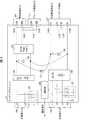
図1は、本発明の実施形態1に係るコンデンサユニット10(電力供給装置)の回路構成を示す図である。図1に示すように、コンデンサユニット10は、AC電源入力端子102、コンデンサ103、整流器104、第一バックアップ用コンデンサ100、DC/DC電源コンバータモジュール105、制御電源出力端子101、AC電源入力端子106、コンデンサ107、整流器108、第二バックアップ用コンデンサ109、および、主回路電源出力端子110を含む。(Details of capacitor unit)
FIG. 1 is a diagram showing a circuit configuration of a capacitor unit 10 (power supply device) according to the first embodiment of the present invention. As shown in FIG. 1, the
(制御電源供給回路)
外部電源からAC電源入力端子102が受容したAC電源は、整流器104により整流され、DC/DC電源コンバータモジュール105により電圧を所望の値に調整された後、制御電源として、制御電源出力端子101からドライバ20に出力される。(Control power supply circuit)
The AC power received by the AC
AC電源入力端子102には、商用電源等によって、AC電源(例えば、単相200V)が入力される。AC電源入力端子102にはコンデンサ103を介して整流器104が接続されている。コンデンサ103は、前記AC電源からノイズ(高調波電流)を低減する。コンデンサ103を通過した交流電圧は、整流器104にて整流される。 An AC power source (for example, single-phase 200V) is input to the AC
整流器104は、直流電圧を、第一バックアップ用コンデンサ100を介してDC/DC電源コンバータモジュール105に出力する。整流器104から出力された直流電流は、DC/DC電源コンバータモジュール105を介して、制御電源出力端子101に入力される。 The
図1、図5、および図6において、「Power supply」との記載は、コンバータを示している。DC/DC電源コンバータモジュール105は、整流器104から出力された直流電流の電圧を、所望の電圧(例えば、24V)へと変換し、所望の電圧に変換した直流電流を、制御電源出力端子101に出力する電圧変換回路である。 In FIGS. 1, 5, and 6, the description "Power supply" refers to a converter. The DC / DC
なお、コンデンサユニット10、図5を用いて後述するコンデンサユニット11、および、図6を用いて後述するコンデンサユニット12において、DC/DC電源コンバータモジュール105は必須ではない。例えば、コンデンサユニット10において、整流器104から出力された直流電流の電圧が、制御電源出力端子101へと入力すべき所望の電圧である場合、電圧変換は不要となるため、DC/DC電源コンバータモジュール105は必要ではない。 The DC / DC
制御電源出力端子101は、DC/DC電源コンバータモジュール105によって電圧が所望の値へと調整された直流電流を、制御電源(ドライバ20の制御回路のための電源)として、ドライバ20に供給する。 The control
なお、コンデンサユニット10、図5を用いて後述するコンデンサユニット11、および、図6を用いて後述するコンデンサユニット12において、制御電源出力端子101が直流電流をドライバ20に供給することは必須ではない。コンデンサユニット10、コンデンサユニット11、および、コンデンサユニット12において、制御電源出力端子101は交流電流を、制御電源としてドライバ20に供給してもよい。その場合、例えば、第一バックアップ用コンデンサ100と制御電源出力端子101との間に、インバータ回路(DC/ACインバータ回路)を挿入してもよい。インバータ回路は、整流器104(第一バックアップ用コンデンサ100)からの直流電流を交流電流に変換し、変換した交流電流を制御電源出力端子101に出力することで、制御電源出力端子101が、制御電源として交流電流をドライバ20に供給してもよい。 It is not essential that the control
第一バックアップ用コンデンサ100は、整流器104と制御電源出力端子101との間に挿入され、例えば、整流器104とDC/DC電源コンバータモジュール105との間に挿入される。すなわち、図1には、第一バックアップ用コンデンサ100の正極端子が、整流器104の正側出力端子とDC/DC電源コンバータモジュール105の正側入力端子との間に接続されている例が示されている。図1に示す回路例においては、第一バックアップ用コンデンサ100の負極端子は、整流器104の負側出力端子とDC/DC電源コンバータモジュール105の負側入力端子との間に接続されている。 The
第一バックアップ用コンデンサ100は、整流器104の出力によって充電され、落雷等を原因とする瞬時電圧低下および瞬時停電などの「入力電圧の急変」が発生すると、放電によりドライバ20の制御回路に制御電源を供給する。言い換えれば、第一バックアップ用コンデンサ100は、落雷等を原因とする入力電圧の急変が発生した場合に、充電電力を、ドライバ20の制御回路に供給する。また、第一バックアップ用コンデンサ100は、モータ30からの回生エネルギーを吸収する。 The
コンデンサユニット10は、落雷等を原因とする入力電圧の急変が発生した場合に、第一バックアップ用コンデンサ100の充電電力を、制御電源として、ドライバ20に供給する。つまり、コンデンサユニット10は、ドライバ20の制御電源を確保し、ドライバ20の制動回路によるドライバ20の主回路の制御を(つまり、モータ30の駆動の制御を)可能とする。入力電圧の急変が発生した場合にも、第一バックアップ用コンデンサ100に残された電荷を利用することによって、ドライバ20の制御回路は動作を続けることができる。 The
(主回路電源供給回路)
外部電源からAC電源入力端子106が受容したAC電源は、整流器108により整流され、主回路電源として、主回路電源出力端子110からドライバ20に出力される。(Main circuit power supply circuit)
The AC power received by the AC
AC電源入力端子106には、商用電源等によって、AC電源(例えば、三相200V)が入力される。AC電源入力端子106にはコンデンサ107を介して整流器108が接続されている。コンデンサ107は、前記AC電源からノイズ(高調波電流)を低減する。コンデンサ107を通過した交流電圧は、整流器108にて整流される。 An AC power source (for example, three-phase 200V) is input to the AC
整流器108は、直流電圧を、第二バックアップ用コンデンサ109を介して第二バックアップ用コンデンサ109に出力する。整流器108から出力された直流電流は、主回路電源出力端子110に入力され、主回路電源出力端子110は、整流器108から出力された直流電流を、主回路電源(ドライバ20の主回路のための電源)として、ドライバ20に供給する。 The
第二バックアップ用コンデンサ109は、整流器108と主回路電源出力端子110との間に挿入される。すなわち、図1には、第二バックアップ用コンデンサ109の正極端子が、整流器108の正側出力端子と主回路電源出力端子110の正側出力端子110Aとの間に接続されている例が示されている。図1に示す回路例においては、第二バックアップ用コンデンサ109の負極端子は、整流器108の負側出力端子と主回路電源出力端子110の負側出力端子110Bとの間に接続されている。 The
第二バックアップ用コンデンサ109は、整流器108の出力によって充電され、落雷等を原因とする瞬時電圧低下および瞬時停電などの「入力電圧の急変」が発生すると、放電によりドライバ20の主回路に主回路電源を供給する。言い換えれば、第二バックアップ用コンデンサ109は、落雷等を原因とする入力電圧の急変が発生した場合に、充電電力を、ドライバ20の主回路に供給する。また、第二バックアップ用コンデンサ109は、モータ30からの回生エネルギーを吸収する。 The
コンデンサユニット10は、落雷等を原因とする入力電圧の急変が発生した場合に、第二バックアップ用コンデンサ109から主回路電源をドライバ20に供給し、つまり、ドライバ20の主回路電源を確保する。入力電圧の急変が発生した場合にも、ドライバ20の主回路は、第二バックアップ用コンデンサ109に残された電荷を利用することができる。 The
以上に説明したとおり、コンデンサユニット10は、2系統のAC電源(例えば、単相200VのAC電源と三相200VのAC電源)の入力を受けて、2系統のDC電源(例えば、DC24Vの制御電源とDC200Vの主回路電源)の出力を行う。コンデンサユニット10は、また、その2系統のDC電源(具体的には、制御電源と主回路電源)について、バックアップを行なっている。すなわち、コンデンサユニット10は、第一バックアップ用コンデンサ100によって制御電源を、第二バックアップ用コンデンサ109によって主回路電源を、バックアップしている。 As described above, the
なお、主回路電源のバックアップ用電力を充電する第二バックアップ用コンデンサ109の電気容量(静電容量、コンデンサ容量)は、制御回路電源のバックアップ用電力を充電する第一バックアップ用コンデンサ100の電気容量よりも大きい。ただし、第二バックアップ用コンデンサ109の電気容量が、第一バックアップ用コンデンサ100の電気容量よりも大きいことは必須ではない。例えば、第二バックアップ用コンデンサ109の電気容量と、第一バックアップ用コンデンサ100の電気容量とは等しくてもよい。 The electric capacity (capacitance, capacitor capacity) of the
(通知部)
コンデンサユニット10は、機能ブロックとして、通知部200を備えている。なお、記載の簡潔性を担保するため、本実施の形態に直接関係のない構成は、説明および図1の回路図から省略している。ただし、実施の実情に則して、コンデンサユニット10は、当該省略された構成を備えてもよい。図1に例示した通知部200は、例えば、CPU(central processing unit)などが、ROM(read only memory)、NVRAM(non-Volatile random access memory)等で実現された記憶装置(不図示)に記憶されているプログラムを不図示のRAM(random access memory)等に読み出して実行することで実現することができる。(Notification section)
The
通知部200は、コンデンサユニット10への入力電圧の急変が発生すると、「入力電圧の急変が発生した」ことを外部に通知する。通知部200は、例えば、AC電源入力端子102およびAC電源入力端子106と接続している。通知部200は、AC電源入力端子102およびAC電源入力端子106の少なくとも一方に入力されるAC電源の入力電圧が急変したことを検出すると、「入力電圧の急変が発生した」ことを、外部の装置(例えば、コントローラ40等)に通知する。 When a sudden change in the input voltage to the
(ドライバとの接続例)
図3は、コンデンサユニット10についてドライバ20(モータ駆動装置)との接続例を示す図である。なお、図3の説明において、コンデンサユニット10Aおよび10Bは、2つの「コンデンサユニット10」の各々を区別するために「コンデンサユニット10」に付合「A」および「B」を付したものである。コンデンサユニット10Aおよびコンデンサユニット10Bの各々を特に区別する必要がない場合は、単に「コンデンサユニット10」と称する。(Example of connection with driver)
FIG. 3 is a diagram showing a connection example of the
図3において、コンデンサユニット10Aは、ドライバ20に、主回路電源(図3における「P−N」)と、制御電源(図3の、紙面上側における「DC24V」)と、を供給するとともに、主回路電源と制御電源とをバックアップしている。 In FIG. 3, the
図3において、コンデンサユニット10Aは、さらに、ドライバ20のブレーキ制御回路に、DC電流(図3の、紙面下側における「DC24V(Brake)」)を供給している。ブレーキ制御回路は、ブレーキ制御回路に供給される電源について入力電圧の急変が発生すると、モータ30にブレーキをかけてモータ30を減速(急減速)させる。また、ブレーキ制御回路は、電断中等においてドライバ20の主回路から駆動電力が供給されていないモータ30の停止を、維持してもよい。 In FIG. 3, the
しかしながら、ブレーキ制御回路がモータ30を急停止させることにより、不測の事態が発生し得る。そこで、コンデンサユニット10Aは、ドライバ20のブレーキ制御回路への電源(ブレーキ電源)をバックアップすることによって、モータ30の急停止に伴う不測の事態の発生を回避している。 However, when the brake control circuit suddenly stops the
コンデンサユニット10Aには、コンデンサユニット10Bが接続されている。コンデンサユニット10Aとコンデンサユニット10Bとは並列接続され、コンデンサユニット10Aとコンデンサユニット10Bとに、外部から、AC電源(図3における「三相AC200V」)が入力されている。 A capacitor unit 10B is connected to the
図3に例示するように、コンデンサユニット10Aには、コンデンサユニット10Bを増設することができ、コンデンサユニット10Aの電気容量が不足する等の事態が発生した場合に、コンデンサユニット10Aの電気容量を擬似的に大きくすることができる。より正確には、コンデンサユニット10Aは、コンデンサユニット10Bと電気的に並列に接続されることにより、コンデンサユニット10Bの電気容量を利用することができる。 As illustrated in FIG. 3, a capacitor unit 10B can be added to the
すなわち、コンデンサユニット10(例えば、コンデンサユニット10A)は、「自装置以外のコンデンサユニット10(コンデンサユニット10B)」と電気的に接続するためのコネクタ(外部コネクタ)を備えている。コンデンサユニット10(例えば、コンデンサユニット10A)は、コネクタで、「自装置以外のコンデンサユニット10(コンデンサユニット10B)」を増設する(電気的に接続する)ことができる。コンデンサユニット10Aとコンデンサユニット10Bとは、互いのコネクタを直結し、または、互いのコネクタを有線でつないで、相互に電気的に並列接続する。 That is, the capacitor unit 10 (for example, the
コンデンサユニット10は、コネクタを介して「自装置以外のコンデンサユニット10」と電気的に並列に接続することによって、(疑似的に)電気容量を増やし、つまり、「自装置以外のコンデンサユニット10」の電気容量を利用することができる。すなわち、コンデンサユニット10は、コネクタで、「自装置以外のコンデンサユニット10(コンデンサユニット10B)」を増設して、(疑似的に)第一バックアップ用コンデンサ100の電気容量を大きくすることができる。したがって、コンデンサユニット10は、第二バックアップ用コンデンサ109の電気容量が不足するといった事態に対応することが可能である。 The
なお、図3には、コンデンサユニット10(図3の例ではコンデンサユニット10A)が、コネクタを介して、1台の「自装置以外のコンデンサユニット10(図3の例ではコンデンサユニット10B)」と電気的に並列接続する例が示されている。しかしながら、コンデンサユニット10が、コネクタを介して、電気的に並列接続することのできる「自装置以外のコンデンサユニット10」は1台に限られない。コンデンサユニット10は、コネクタを介して、複数台(例えば、2台または3台)の「自装置以外のコンデンサユニット10」と、電気的に並列接続することができる。言い換えれば、コンデンサユニット10は、「自装置以外のコンデンサユニット10」と電気的に接続するためのコネクタ(外部コネクタ)を、複数備えている。 In addition, in FIG. 3, the capacitor unit 10 (
また、図3には、コンデンサユニット10(図3の例ではコンデンサユニット10A)のコネクタと、別のコンデンサユニット10(図3の例ではコンデンサユニット10B)のコネクタとが、有線で、電気的に接続される例が示されている。しかしながら、複数のコンデンサユニット10の各々のコネクタ間が、有線で電気的に接続させることは必須ではない。複数のコンデンサユニット10の各々のコネクタ間が直結してもよい。例えば、コンデンサユニット10Aのコネクタと、コンデンサユニット10Bのコネクタとは直結してもよい。 Further, in FIG. 3, the connector of the capacitor unit 10 (
なお、ここで述べた「コネクタ(外部コネクタ)」は、図6に示す「コンデンサ増設端子112」に相当し、その詳細は図6を用いて後述する。 The "connector (external connector)" described here corresponds to the "capacitor expansion terminal 112" shown in FIG. 6, and the details thereof will be described later with reference to FIG.
(従来の電力供給システムとの比較)
図4は、電力供給システム1および従来の電力供給システムの各々の概要および両者の比較を示している。図4の(A)は、従来の電力供給システムの全体概要を示す図である。従来の電力供給システムは、ドライバ97の主回路に、従来のコンデンサユニット99が主回路電源を供給し、ドライバ97の制御回路に、UPS(Uninterruptible Power Supply、無停電電源装置)98が制御電源を供給する構成である。図4の(B)は、図2に例示した電力供給システム1のうち、特にコンデンサユニット10がドライバ20に供給する電力(電源)について説明する図である。図4の(C)は、図4の(A)に例示した「従来の電力供給システム」と、図4の(B)に例示した電力供給システム1と、を比較する表である。図4の(C)の表において、「ドライバ97+UPS98+従来のコンデンサユニット99」の「組合せ」は、「従来の電力供給システム」を示し、「ドライバ20+コンデンサユニット10」の「組合せ」は、電力供給システム1を示している。(Comparison with conventional power supply system)
FIG. 4 shows an outline of each of the power supply system 1 and the conventional power supply system, and a comparison between the two. FIG. 4A is a diagram showing an overall outline of a conventional power supply system. In the conventional power supply system, the conventional capacitor unit 99 supplies the main circuit power to the main circuit of the driver 97, and the UPS (Uninterruptible Power Supply) 98 supplies the control power to the control circuit of the driver 97. It is a configuration to supply. FIG. 4B is a diagram illustrating the electric power (power supply) supplied to the
以上に構成を説明した電力供給システム1および従来の電力供給システムについて、先ず、両者に共通する、落雷等を原因とする瞬時電圧低下および瞬時停電などの「入力電圧の急変」の発生に伴うリスクについて、説明しておく。 Regarding the power supply system 1 and the conventional power supply system whose configurations have been described above, first of all, the risks associated with the occurrence of "sudden changes in input voltage" such as instantaneous voltage drop and instantaneous power failure due to lightning strikes, etc., which are common to both. Will be explained.
(入力電圧の急変に伴うリスク)
ドライバ20およびドライバ97の動作中に、落雷等を原因とする瞬時電圧低下および瞬時停電などの「入力電圧の急変」が発生すると、ドライバ20またはドライバ97が制御している複数のメカ同士が干渉し合うなどして、ワークの破損等が発生し得る。例えば、液剤充填に係る作業においては複数軸が同期して動くため、入力電圧の急変時に、慣性の異なる複数のメカ同士(例えば、ノズル部分のメカと搬送部分のメカと)が干渉したり衝突したりすることによって、高価なノズルが折れることがある。より具体的には、長いコンベヤはイナーシャが大であるのに対し、液剤充填機はイナーシャが小さいため、「入力電圧の急変」が発生した場合、位置ズレが大きくなり、高価なノズルが割れることがある。また、液剤充填機の稼働する無菌空間等での復旧作業には、莫大な工数が掛かるだけでなく、廃棄ロスおよび液剤の補充等に莫大な額の損害が発生し得る。(Risk associated with sudden changes in input voltage)
If a "sudden change in input voltage" such as a momentary voltage drop or a momentary power failure due to a lightning strike occurs during the operation of the
ここで、落雷等を原因とする入力電圧の急変(瞬時電圧低下および瞬時停電など)時にモータ30等に正常な停止をさせるには、「ドライバ20またはドライバ97」の主回路および制御回路の双方に電力を供給する必要がある。すなわち、「ドライバ20またはドライバ97」の主回路電源だけでなく、制御電源もバックアップされていなくては、落雷等を原因とする入力電圧の急変に伴って、ノズルの破損等を含む巨額の損失を被ることになる。 Here, in order to cause the
しかしながら、そのような液剤充填機が稼働している工場等において、ドライバ20またはドライバ97の電源をバックアップするための機器の設置スペースは、限られていることが多い。 However, in factories and the like where such a liquid agent filling machine is operating, the installation space of equipment for backing up the power supply of the
(従来の電力供給システム)
図4の(A)に例示する従来の電力供給システムにおいては、「入力電圧の急変」に伴う上述のリスクの回避策として、つまり、入力電圧の急変時に複数軸(複数のメカ)を同期させたまま停止させるために、以下のような構成が採用されていた。(Conventional power supply system)
In the conventional power supply system illustrated in FIG. 4A, as a workaround for the above-mentioned risk associated with "sudden change in input voltage", that is, when the input voltage suddenly changes, a plurality of axes (plurality of mechanisms) are synchronized. The following configuration was adopted to stop it while it was still there.
すなわち、従来、上述の特許文献1に係るような「ドライバ97の主回路電源のみをバックアップ可能な、従来のコンデンサユニット99」と、「ドライバ97の制御電源のみをバックアップするUPS98」と、を併用していた。図4の(A)に例示するように、従来の電力供給システムにおいて、「ドライバ97の制御電源」については、「ドライバ97の主回路電源」をバックアップする従来のコンデンサユニット99とは別の、UPS98等によってバックアップしていた。 That is, conventionally, the "conventional capacitor unit 99 capable of backing up only the main circuit power supply of the driver 97" and the "UPS98 backing up only the control power supply of the driver 97" as described in Patent Document 1 described above are used in combination. Was. As illustrated in FIG. 4A, in the conventional power supply system, the "control power supply of the driver 97" is different from the conventional capacitor unit 99 that backs up the "main circuit power supply of the driver 97". It was backed up by UPS98 etc.
しかしながら、上述の通り、工場等においてはドライバ97の電源をバックアップするための場所が限られているため、ドライバ97の制御電源のバックアップに用いるUPS98は、小型で高性能だが高価なものを選択せざるを得ない。また、UPS09は、バッテリの定期交換等のメンテナンスが必要な上、一般に、電気容量が不足する場合に増設が困難である。 However, as described above, since the place for backing up the power supply of the driver 97 is limited in factories and the like, the UPS98 used for backing up the control power supply of the driver 97 should be small, high-performance, but expensive. I have no choice but to do it. In addition, UPS09 requires maintenance such as periodic battery replacement, and is generally difficult to expand when the electric capacity is insufficient.
(本実施形態に係る電力供給システム)
図4の(B)に例示するコンデンサユニット10は、ドライバ20の主回路電源および制御電源の2系統の電源出力を行ない、主回路電源および制御電源の双方をバックアップしている。言い換えれば、コンデンサユニット10は、「モータ30を駆動させるための主回路電源(モータ駆動電源)」および「モータ30の駆動(つまり、主回路)を制御するための制御電源」の両者をバックアップする。(Power supply system according to this embodiment)
The
したがって、落雷等を原因とする入力電圧の急変が発生した場合であっても、コンデンサユニット10がドライバ20への電源供給を継続するので、例えば、複数軸は同期して制御され、メカ間の衝突が回避される。また、コンデンサユニット10は、ドライバ20に主回路電源および制御電源を供給するとともに、両者のバックアップを行ない、さらに、回生/力行のエネルギー活用に対応している。さらに、電力供給システム1においては、コンデンサユニット10がドライバ20の制御電源をバックアップするため、UPS98が不要であり、また当然に、UPS98のための設置スペースが不要となる。 Therefore, even if a sudden change in the input voltage occurs due to a lightning strike or the like, the
(比較表)
図4の(C)を用いて、図4の(A)に例示した「従来の電力供給システム」と、図4の(B)に例示した電力供給システム1と、の違いについて整理しておく。なお、図4の(C)に示されている通り、「従来の電力供給システム」と電力供給システム1とで、「主回路電源」および「出力」についてはほとんど違いが無いので、「主回路電源」および「出力」について詳細は略記する。(Comparison table)
Using (C) of FIG. 4, the difference between the "conventional power supply system" illustrated in (A) of FIG. 4 and the power supply system 1 exemplified in (B) of FIG. 4 will be summarized. .. As shown in FIG. 4C, there is almost no difference in "main circuit power supply" and "output" between the "conventional power supply system" and the power supply system 1, so that the "main circuit" is used. Details of "power supply" and "output" are omitted.
「従来の電力供給システム(ドライバ97+UPS98+従来のコンデンサユニット99)」において、「制御電源」は「単相AC電源」である。これに対して、電力供給システム1(ドライバ20+コンデンサユニット10)において、「制御電源」は「DC電源(例えば、DC24V)」である。したがって、電力供給システム1においてコンデンサユニット10は、第一バックアップ用コンデンサ100によって、ドライバ20の制御電源をバックアップすることができる。 In the "conventional power supply system (driver 97 + UPS98 + conventional capacitor unit 99)", the "control power supply" is a "single-phase AC power supply". On the other hand, in the power supply system 1 (
また、従来のコンデンサユニット99は、「ブレーキ回路(ブレーキ制御回路)」を外付けでコントロールすることができず、言い換えれば、従来のコンデンサユニット99は、ブレーキ回路のための電源をバックアップすることができない。これに対し、電力供給システム1において、ドライバ20は「ブレーキ回路(ブレーキ制御回路)」を内蔵しており、コンデンサユニット10は、図3に例示したように、24VのDC電流をドライバ20のブレーキ制御回路に供給する。そして、コンデンサユニット10は、第一バックアップ用コンデンサ100の充電電力を、ドライバ20のブレーキ制御回路に供給することができ、つまり、ブレーキ電源をバックアップすることができる。なお、第一バックアップ用コンデンサ100によるブレーキ電源のバックアップについて、詳細は図6および図7を用いて後述する。 Further, the conventional capacitor unit 99 cannot externally control the "brake circuit (brake control circuit)", in other words, the conventional capacitor unit 99 can back up the power supply for the brake circuit. Can not. On the other hand, in the power supply system 1, the
さらに、従来のコンデンサユニット99は、「増設(つまり、自装置以外の、従来のコンデンサユニット99との電気的な接続)」ができず(不可)、「対応ドライバ容量(つまり、吸収可能な回生エネルギー)」は「1kW以下」であった。これに対し、コンデンサユニット10は、「増設」が「可能」であり、「増設」によって、「対応ドライバ容量」を「3kW以下」とすることができる。 Further, the conventional capacitor unit 99 cannot be "expanded (that is, electrically connected to the conventional capacitor unit 99 other than its own device)" (impossible), and "corresponding driver capacity (that is, regenerative regeneration that can be absorbed)". Energy) ”was“ 1 kW or less ”. On the other hand, the
(コンデンサユニットが実現する機能)
コンデンサユニット10は、従来のコンデンサユニットが実現することのできなかった下記の3つの機能を実現することができる。第一に、コンデンサユニット10は、ドライバ20の主回路電源および制御電源の双方をバックアップすることができる。第二に、コンデンサユニット10は、「自装置以外のコンデンサユニット10」を増設することによって、第一バックアップ用コンデンサ100および第二バックアップ用コンデンサ109の少なくとも一方の電気容量の不足に対応することができる。また、コンデンサユニット10は、「自装置以外のコンデンサユニット10」を増設することによって、大きな回生エネルギーにも対応することができる。例えば、コンデンサユニット10は、3kWの回生エネルギーにも対応することができ、回生エネルギーが大きい大型の液剤充填機等にも対応することができる。第三に、コンデンサユニット10は、瞬時電圧低下および瞬時停電などの「入力電圧の急変」を検知して、「入力電圧の急変」を外部に通知する(例えば、「入力電圧の急変」を検知したことを外部に通知する信号を出力する)機能を備えている。以下、コンデンサユニット10の備える「入力電圧の急変を通知する」機能について、詳細を説明する。(Functions realized by the capacitor unit)
The
(「入力電圧の急変を通知する」機能)
コンデンサユニット10は、「入力電圧の急変」を検知して外部出力に出す機能を備えている。図1に例示するコンデンサユニット10は、「入力電圧の急変」を検知すると通知信号を外部に出力する通知部200を備えている。コンデンサユニット10は、「入力電圧の急変」を検知した通知部200の出力する通知信号をトリガとして、コントローラ40等に、「入力電圧の急変」時に必要な処理を実行させることができるとの効果を奏する。例えば、「入力電圧の急変」を通知されたコントローラ40は、複数のドライバ20に、複数のドライバ20の各々に接続されているモータ30を同期させて停止させることができる。("Notify sudden change of input voltage" function)
The
〔実施形態2〕
本発明の実施形態2について、図5に基づいて説明すれば、以下のとおりである。なお、説明の便宜上、前記実施形態にて説明した部材と同じ機能を有する部材については、同じ符号を付記し、その説明を省略する。本実施形態におけるコンデンサユニット11が、上述の実施形態1におけるコンデンサユニット10と異なるのは、本実施形態に係るコンデンサユニット11の電源入力は1つであるという点である。以下、図5を用いて、コンデンサユニット11の詳細について説明する。[Embodiment 2]
The second embodiment of the present invention will be described below with reference to FIG. For convenience of explanation, the same reference numerals will be added to the members having the same functions as the members described in the above-described embodiment, and the description thereof will be omitted. The
図5は、本発明の実施形態2に係るコンデンサユニット11(電力供給装置)の回路構成を示す図である。コンデンサユニット11は、三相200VのAC電源を供給され、24VのDC電流をドライバ20の制御回路に供給するとともに、200VのDC電流をドライバ20の主回路に供給する。すなわち、外部電源からAC電源入力端子106が受容したAC電源は、整流器108により整流され、DC/DC電源コンバータモジュール105により電圧を所望の値に調整された後、制御電源として、制御電源出力端子101からドライバ20に出力される。また、外部電源からAC電源入力端子106が受容したAC電源は、整流器108により整流され、主回路電源として、主回路電源出力端子110からドライバ20に出力される。 FIG. 5 is a diagram showing a circuit configuration of a capacitor unit 11 (power supply device) according to a second embodiment of the present invention. The
具体的には、AC電源入力端子106には、商用電源等によって、AC電源(例えば、三相200V)が入力され、コンデンサ107は、AC電源入力端子106に入力されたAC電源からノイズ(高調波電流)を低減する。コンデンサ107を通過した交流電圧は、整流器108にて整流される。整流器108は、直流電圧を、第一バックアップ用コンデンサ100を介して、DC/DC電源コンバータモジュール105および主回路電源出力端子110へと出力する。すなわち、整流器108は、第一バックアップ用コンデンサ100を介して、DC/DC電源コンバータモジュール105および主回路電源出力端子110に接続している。 Specifically, an AC power supply (for example, three-phase 200V) is input to the AC power
第一バックアップ用コンデンサ100を介して整流器108と接続しているDC/DC電源コンバータモジュール105は、整流器108から出力された直流電流の電圧を、所望の電圧(例えば、24V)へと変換する。DC/DC電源コンバータモジュール105は、所望の電圧に変換した直流電流を、制御電源出力端子101に出力する。制御電源出力端子101は、DC/DC電源コンバータモジュール105によって電圧が所望の値に調整された直流電流を、制御電源(ドライバ20の制御回路のための電源)として、ドライバ20に供給する。 The DC / DC
同様に、第一バックアップ用コンデンサ100を介して整流器108と接続している主回路電源出力端子110は、整流器108から出力された直流電流を、主回路電源(ドライバ20の主回路のための電源)として、ドライバ20に供給する。 Similarly, the main circuit power
(制御電源のバックアップ)
第一バックアップ用コンデンサ100は、整流器108と制御電源出力端子101との間に挿入され、例えば、整流器108とDC/DC電源コンバータモジュール105との間に挿入される。すなわち、図5には、第一バックアップ用コンデンサ100の正極端子が、整流器108の正側出力端子とDC/DC電源コンバータモジュール105の正側入力端子との間に接続されている例が示されている。図5に示す回路例においては、第一バックアップ用コンデンサ100の負極端子は、整流器108の負側出力端子とDC/DC電源コンバータモジュール105の負側入力端子との間に接続されている。第一バックアップ用コンデンサ100は、整流器108の出力によって充電され、落雷等を原因とする瞬時電圧低下および瞬時停電などの「入力電圧の急変」が発生すると、放電によりドライバ20の制御回路に制御電源を供給する。(Backup of control power supply)
The
(主回路電源のバックアップ)
コンデンサユニット11において、整流器108と主回路電源出力端子110との間に挿入された第一バックアップ用コンデンサ100は、主回路電源のバックアップも行っている。図5において、第一バックアップ用コンデンサ100の正極端子は、整流器108の正側出力端子と主回路電源出力端子110の正側出力端子110Aとの間に接続されている。また、第一バックアップ用コンデンサ100の負極端子は、整流器108の負側出力端子と主回路電源出力端子110の負側出力端子110Bとの間に接続されている。(Backup of main circuit power supply)
In the
第一バックアップ用コンデンサ100は、整流器108の出力によって充電され、落雷等を原因とする瞬時電圧低下および瞬時停電などの「入力電圧の急変」が発生すると、放電によりドライバ20の主回路に主回路電源を供給する。言い換えれば、第一バックアップ用コンデンサ100は、落雷等を原因とする入力電圧の急変が発生した場合に、充電電力を、ドライバ20の主回路に供給する。 The
また、第一バックアップ用コンデンサ100は、モータ30からの回生エネルギーを吸収する。 Further, the
以上に説明したとおり、コンデンサユニット11は、1系統のAC電源(例えば、三相200VのAC電源)の入力を受けて、2系統のDC電源(例えば、DC24Vの制御電源とDC200Vの主回路電源)の出力を行う。コンデンサユニット11は、また、その2系統のDC電源(具体的には、制御電源と主回路電源)について、バックアップを行なっている。すなわち、コンデンサユニット11は、第一バックアップ用コンデンサ100によって、制御電源と主回路電源とについて、バックアップを行なっている。 As described above, the
すなわち、コンデンサユニット11(電力供給装置)は、ドライバ20(モータ駆動装置)の、モータ30にモータ駆動電力を供給する主回路に電力を供給する電力供給装置であって、外部の交流電源から入力された交流を整流する整流器108(整流回路)と、ドライバ20の、前記主回路を制御する制御回路に電力を供給する制御電源出力端子101と、を備え、(1)整流器108と制御電源出力端子101との間には第一バックアップ用コンデンサ100が挿入されており、(2)第一バックアップ用コンデンサ100は整流器108の出力により充電される。例えば、(1)整流器108の正側出力端子には第一バックアップ用コンデンサ100の正極端子が電気的に接続されており、(2)整流器108の負側出力端子には第一バックアップ用コンデンサ100の負極端子が電気的に接続されている。 That is, the capacitor unit 11 (power supply device) is a power supply device that supplies power to the main circuit of the driver 20 (motor drive device) that supplies the motor drive power to the
図5において、(1)整流器108の正側出力端子と制御電源出力端子101の正側101Aとの間には第一バックアップ用コンデンサ100の正極端子が電気的に接続されている。また、(2)整流器108の負側出力端子と制御電源出力端子101の負側101Bとの間には第一バックアップ用コンデンサ100の負極端子が電気的に接続されている。 In FIG. 5, (1) the positive electrode terminal of the
前記の構成によれば、コンデンサユニット11は、整流器108と、ドライバ20の制御回路に電力を供給する制御電源出力端子101と、の間に第一バックアップ用コンデンサ100を備えている。そして、第一バックアップ用コンデンサ100は、整流器108の出力によって充電される。 According to the above configuration, the
したがって、コンデンサユニット11は、落雷等を原因とする瞬時電圧低下および瞬時停電などの入力電圧の急変が発生した場合であっても、第一バックアップ用コンデンサ100の充電電力を、ドライバ20の制御回路に供給することができるとの効果を奏する。 Therefore, the
また、コンデンサユニット11は、ドライバ20を変更することなく、ドライバ20について、落雷等を原因とする瞬時電圧低下および瞬時停電などの入力電圧の急変への対策を行なうことができるとの効果を奏する。 Further, the
通知部200は、コンデンサユニット11への入力電圧の急変が発生すると、「入力電圧の急変が発生した」ことを外部に通知する。通知部200は、AC電源入力端子106と接続しており、AC電源入力端子106に入力されるAC電源の入力電圧が急変したことを検出すると、「入力電圧の急変が発生した」ことを、外部の装置(例えば、コントローラ40等)に通知する。 When a sudden change in the input voltage to the
なお、前述の通り、コンデンサユニット11において、DC/DC電源コンバータモジュール105は必須ではなく、整流器108から出力された直流電流の電圧が、制御電源出力端子101へと入力すべき所望の電圧である場合、電圧変換は不要となる。また、第一バックアップ用コンデンサ100と制御電源出力端子101との間に、インバータ回路(DC/ACインバータ回路)を挿入し、制御電源出力端子101が、制御電源として交流電流をドライバ20に供給してもよい。 As described above, in the
〔実施形態3〕
本発明の実施形態3について、図6および図7に基づいて説明すれば、以下のとおりである。なお、説明の便宜上、前記実施形態にて説明した部材と同じ機能を有する部材については、同じ符号を付記し、その説明を省略する。本実施形態に係るコンデンサユニット12(電力供給装置)についての理解を容易にするため、先ず、コンデンサユニット12について、ドライバ20(モータ駆動装置)との接続例を、図7を用いて説明する。[Embodiment 3]
The third embodiment of the present invention will be described below with reference to FIGS. 6 and 7. For convenience of explanation, the same reference numerals will be added to the members having the same functions as the members described in the above-described embodiment, and the description thereof will be omitted. In order to facilitate understanding of the capacitor unit 12 (power supply device) according to the present embodiment, first, a connection example of the
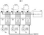
(ドライバとの接続例)
図7は、コンデンサユニット12について、ドライバ20との接続例を示す図である。図7には、マスタ装置としてのコントローラ40が、フィールドネットワーク60を介して、複数のスレーブ装置(具体的には、ドライバ20A、20B、および20C)と接続する例が示されている。ドライバ20A、20B、および20Cの各々は、コンデンサユニット12A、12B、および12Cの各々によって、電力を供給されている。コンデンサユニット12A、12B、および12Cの各々には、外部から、三相200VのAC電源を供給されている。(Example of connection with driver)
FIG. 7 is a diagram showing a connection example of the
なお、図7の説明において、ドライバ20A、20B、および20Cは、3つの「ドライバ20」の各々を区別するために「ドライバ20」に付合「A」、「B」、および「C」を付したものである。ドライバ20A、20B、および20Cの各々を特に区別する必要がない場合は、単に「ドライバ20」と称する。同様に、コンデンサユニット12A、12B、および12Cは、3つの「コンデンサユニット12」の各々を区別するために「コンデンサユニット12」に付合「A」、「B」、および「C」を付したものである。コンデンサユニット12A、12B、および12Cの各々を特に区別する必要がない場合は、単に「コンデンサユニット12」と称する。 In the description of FIG. 7, the
図7に示すように、コンデンサユニット12は、ドライバ20に、主回路電源(図7における「P−N」)と、制御電源(図7の、紙面上側における「DC24V」)と、を供給するとともに、主回路電源と制御電源とをバックアップしている。また、コンデンサユニット12は、ドライバ20に、ブレーキ電源(図7の、紙面下側における「DC24V(Brake)」)を供給するとともに、ブレーキ電源をバックアップしている。言い換えれば、コンデンサユニット12は、ドライバ20に対し、主回路電源、制御電源、および、ブレーキ電源の3系統の電源出力を行なうとともに、主回路電源、制御電源、および、ブレーキ電源のバックアップを行なっている。コンデンサユニット12は、落雷等を原因とする入力電圧の急変が発生した場合にドライバ20のブレーキ制御回路に電力を供給することによって、ドライバ20が意図せずモータ30にブレーキをかけてしまう事態を防いでいる。さらに、コンデンサユニット12は、回生/力行のエネルギー活用に対応している。 As shown in FIG. 7, the
なお、前述の通り、コンデンサユニット12において、DC/DC電源コンバータモジュール105は必須ではなく、整流器104から出力された直流電流の電圧が、制御電源出力端子101へと入力すべき所望の電圧である場合、電圧変換は不要となる。また、第一バックアップ用コンデンサ100と制御電源出力端子101との間に、インバータ回路(DC/ACインバータ回路)を挿入し、制御電源出力端子101が、制御電源として交流電流をドライバ20に供給してもよい。 As described above, in the
(コンデンサユニットの概要)
これまで図7を用いて概要を説明してきたコンデンサユニット12について、次に、その詳細を、図6を用いて説明していく。なお、図6に回路構成を例示するコンデンサユニット12は、図1に回路構成を例示するコンデンサユニット10と、以下の3点において異なっている。(Overview of capacitor unit)
Next, the details of the
第1に、コンデンサユニット12はブレーキ電源出力端子111を備え、ドライバ20のブレーキ制御回路に電力(ブレーキ電源)を供給するとともに、ブレーキ電源をバックアップしている。具体的には、コンデンサユニット12(電力供給装置)において、(1)第一バックアップ用コンデンサ100の正極端子は、整流器104の正側出力端子と、「入力電圧の急変が発生した場合に主回路の動作から独立してモータ30を減速させる」ブレーキ制御回路に電力を供給する出力端子であるブレーキ電源出力端子111の正側111Aと、の間に電気的に接続されており、(2)第一バックアップ用コンデンサ100の負極端子は、整流器104の負側出力端子と、ブレーキ電源出力端子111の負側111Bと、の間に電気的に接続されている。言い換えれば、コンデンサユニット12において、第一バックアップ用コンデンサ100は、整流器104と、「入力電圧の急変が発生した場合に主回路の動作から独立してモータ30を減速させる」ブレーキ制御回路に電力を供給するブレーキ電源出力端子111と、の間に挿入されている。 First, the
前記の構成によれば、コンデンサユニット12は、整流器104と、「入力電圧の急変が発生した場合に主回路の動作から独立してモータ30を減速させる」ブレーキ制御回路に電力を供給するブレーキ電源出力端子111(出力端子)と、の間に第一バックアップ用コンデンサ100を備えている。そして、コンデンサユニット12は、落雷等を原因とする入力電圧の急変が発生した場合、「入力電圧の急変が発生した場合に主回路の動作から独立してモータ30を減速させる」ブレーキ制御回路に、第一バックアップ用コンデンサ100の充電電力を供給する。 According to the above configuration, the
ここで、前記ブレーキ制御回路への電源供給がバックアップされていない状態で、落雷等を原因とする入力電圧の急変が発生した場合、前記ブレーキ制御回路は、ドライバ20の主回路の動作から独立してモータ30を減速させる。また、前記ブレーキ制御回路は、電断中等においてドライバ20の主回路から駆動電力が供給されていないモータ30の停止を、維持してもよい。 Here, if a sudden change in the input voltage due to a lightning strike or the like occurs while the power supply to the brake control circuit is not backed up, the brake control circuit becomes independent of the operation of the main circuit of the
しかしながら、例えば、前記主回路によるモータ30の制御から独立して、前記ブレーキ制御回路がモータ30を急減速させた場合、ワークの破損等、前記主回路がモータ30を制御している時には発生しなかった不測の事態が、発生し得る。 However, for example, when the brake control circuit suddenly decelerates the
これに対して、コンデンサユニット12は、落雷等を原因とする入力電圧の急変が発生した場合に、前記ブレーキ制御回路への電源供給をバックアップする。したがって、前記電力供給装置は、落雷等を原因とする入力電圧の急変が発生した場合であっても、前記ブレーキ制御回路が前記主回路の動作から独立して前記モータを減速させることにより前述のような不測の事態が発生するのを回避することができるとの効果を奏する。 On the other hand, the
なお、前述の通り、コンデンサユニット12にとって、ブレーキ制御回路がドライバ20に内蔵されていることは必須ではない。コンデンサユニット12は、ドライバ20から独立して存在する、「入力電圧の急変が発生した場合に、ドライバ20の主回路の動作から独立してモータ30を減速させるブレーキ」を制御する回路(制御回路)または装置にブレーキ電源を供給してもよい。コンデンサユニット12は、ドライバ20から独立して存在する、「入力電圧の急変が発生した場合に、ドライバ20の主回路の動作から独立してモータ30を減速させるブレーキ」を制御する回路(制御回路)または装置のブレーキ電源をバックアップしてもよい。 As described above, it is not essential for the
第2に、コンデンサユニット12はコンデンサ増設端子112を備え、自装置以外のコンデンサユニット12と電気的に並列接続することによって、(疑似的に)自装置の第二バックアップ用コンデンサ109の電気容量を大きくすることができる。すなわち、コンデンサユニット12は、自装置以外のコンデンサユニット12の第二バックアップ用コンデンサ109の電気容量を利用することができる。 Secondly, the
具体的には、コンデンサユニット12は、第二バックアップ用コンデンサ109に電気的に接続されたコンデンサ増設端子112(コネクタ)をさらに備えている。そして、コンデンサユニット12のコンデンサ増設端子112は、自装置以外のコンデンサユニット12の、(1)コンデンサ増設端子112、または、(2)ドライバ20の主回路に電力を供給する主回路電源出力端子110と接続可能である。 Specifically, the
例えば、コンデンサユニット12Aのコンデンサ増設端子112は、コンデンサユニット12Bの「コンデンサ増設端子112、または、主回路電源出力端子110」と接続可能である。なお、コンデンサユニット12Aのコンデンサ増設端子112は、コンデンサユニット12Bの「コンデンサ増設端子112、または、主回路電源出力端子110」と、有線で接続されてもよいし、直結されてもよい。 For example, the capacitor expansion terminal 112 of the
そのため、自装置以外のコンデンサユニット12の、(1)コンデンサ増設端子112、または、(2)ドライバ20の主回路に電力を供給する主回路電源出力端子110が、コンデンサ増設端子112に電気的に並列接続されると、自装置以外のコンデンサユニット12の第二バックアップ用コンデンサ109と、自装置の第二バックアップ用コンデンサ109とは、電気的に並列接続されることになる。つまり、コンデンサユニット12は、自装置以外のコンデンサユニット12の、(1)コンデンサ増設端子112、または、(2)ドライバ20の主回路に電力を供給する主回路電源出力端子110を、コンデンサ増設端子112に電気的に並列接続させることにより、自装置以外のコンデンサユニット12の第二バックアップ用コンデンサ109の電気容量を利用することができる。例えば、コンデンサユニット12Aのコンデンサ増設端子112に、コンデンサユニット12Bの「コンデンサ増設端子112、または、主回路電源出力端子110」を電気的に並列接続させることにより、コンデンサユニット12Aは、コンデンサユニット12Bの第二バックアップ用コンデンサ109の電気容量を利用する。 Therefore, (1) the capacitor expansion terminal 112 or (2) the main circuit power
したがって、コンデンサユニット12は、自装置の第二バックアップ用コンデンサ109の電気容量が不足する場合等において、自装置以外のコンデンサユニット12の、(1)コンデンサ増設端子112、または、(2)ドライバ20の主回路に電力を供給する主回路電源出力端子110を、コンデンサ増設端子112に電気的に並列接続させることにより、自装置に接続している自装置以外のコンデンサユニット12の第二バックアップ用コンデンサ109の電気容量を利用することができるとの効果を奏する。 Therefore, when the electric capacity of the
(コンデンサに係る注記)
なお、コンデンサユニット12は、自装置の第二バックアップ用コンデンサ109の電気容量を大きくするために、自装置の筺体の内側または外側に不図示のコンデンサを部品としてさらに設けてもよい。そして、自装置の筺体の内側または外側に追加したこのコンデンサを、第二バックアップ用コンデンサ109に並列接続させることによって、第二バックアップ用コンデンサ109の電気容量を大きくしてもよい。(Notes on capacitors)
The
また、上述までの第一バックアップ用コンデンサ100および第二バックアップ用コンデンサ109の各々は、1つのコンデンサ(コンデンサ部品)によって実現してもよいし、2つ以上のコンデンサ(コンデンサ部品)によって実現してもよい。 Further, each of the
第3に、コンデンサユニット12において、コンデンサユニット10における第一バックアップ用コンデンサ100と、第二バックアップ用コンデンサ109と、は電気的に並列接続されている。具体的には、コンデンサユニット12は、コンデンサユニット10と同様に、ドライバ20の主回路に電力を供給する主回路電源出力端子110の正側出力端子110Aと負側出力端子110Bとの間に接続された第二バックアップ用コンデンサ109を備えている。そして、第一バックアップ用コンデンサ100の正極端子は第二バックアップ用コンデンサ109の正極端子と電気的に接続し、第一バックアップ用コンデンサ100の負極端子は第二バックアップ用コンデンサ109の負極端子と電気的に接続している。 Third, in the
前記の構成によれば、コンデンサユニット12は、ドライバ20の主回路に電力を供給する主回路電源出力端子110の正側出力端子110Aと負側出力端子110Bとの間に接続された第二バックアップ用コンデンサ109を備えている。そして、コンデンサユニット12の第一バックアップ用コンデンサ100の正極端子は第二バックアップ用コンデンサ109の正極端子と電気的に接続し、第一バックアップ用コンデンサ100の負極端子は第二バックアップ用コンデンサ109の負極端子と電気的に接続している。すなわち、コンデンサユニット12において、第一バックアップ用コンデンサ100と、第二バックアップ用コンデンサ109とは、電気的に並列接続されている。 According to the above configuration, the
したがって、コンデンサユニット12は、入力電圧の急変が発生した場合、第一バックアップ用コンデンサ100に電気的に並列接続されている第二バックアップ用コンデンサ109の充電電力を、ドライバ20の制御回路に供給することができるとの効果を奏する。 Therefore, when a sudden change in the input voltage occurs, the
(コンデンサユニットの詳細)
図6は、本発明の実施形態3に係るコンデンサユニット12の回路構成を示す図である。なお、前述の通り、コンデンサユニット12は、コンデンサユニット10の構成に加えて、ブレーキ電源出力端子111およびコンデンサ増設端子112をさらに備えている。また、コンデンサユニット12においては、第一バックアップ用コンデンサ100と、第二バックアップ用コンデンサ109と、が電気的に並列に接続されている。そして、第一バックアップ用コンデンサ100と、第二バックアップ用コンデンサ109との間には、ダイオード113が挿入されている。これらの構成以外は、コンデンサユニット12の構成とコンデンサユニット10の構成とは同様であり、コンデンサユニット12の構成のうち、コンデンサユニット10と同様の構成については、説明を省略する。(Details of capacitor unit)
FIG. 6 is a diagram showing a circuit configuration of the
ブレーキ電源出力端子111は、DC/DC電源コンバータモジュール105に接続されており、ブレーキ電源出力端子111は、DC/DC電源コンバータモジュール105によって電圧を調整された直流電流を、ブレーキ電源として、ドライバ20に供給する。ここで、ブレーキ電源出力端子111は、DC/DC電源コンバータモジュール105を介して、第一バックアップ用コンデンサ100に接続している。入力電圧の急変が発生すると、整流器108の出力によって第一バックアップ用コンデンサ100に充電されていた電力が、ブレーキ電源出力端子111に供給される。言い換えれば、第一バックアップ用コンデンサ100は、整流器108の出力によって充電され、入力電圧の急変が発生すると、放電によって、(1)ドライバ20の制御回路に制御電源を供給し、(2)ドライバ20のブレーキ制御回路にブレーキ電源を供給する。 The brake power
コンデンサ増設端子112は、第二バックアップ用コンデンサ109に電気的に接続されている。具体的には、ドライバ20の主回路に電力を供給する主回路電源出力端子110の正側出力端子110Aと、コンデンサ増設端子112の正極112Aとは、各々、第二バックアップ用コンデンサ109の正極端子に電気的に接続されている。また、ドライバ20の主回路に電力を供給する主回路電源出力端子110の負側出力端子110Bと、コンデンサ増設端子112の負極112Bとは、各々、コンデンサ増設端子112の負極112Bに電気的に接続されている。 The capacitor expansion terminal 112 is electrically connected to the
そして、コンデンサ増設端子112の正極112Aには、自装置以外のコンデンサユニット12の、(1)コンデンサ増設端子112の正極112A、または、(2)ドライバ20の主回路に電力を供給する主回路電源出力端子110の正側出力端子110Aが接続される。また、コンデンサ増設端子112の負極112Bには、自装置以外のコンデンサユニット12の、(1)コンデンサ増設端子112の負極112B、または、(2)ドライバ20の主回路に電力を供給する主回路電源出力端子110の負側出力端子110Bが接続される。 Then, the
例えば、コンデンサユニット12Aのコンデンサ増設端子112と、コンデンサユニット12Bの、(1)コンデンサ増設端子112、または、(2)主回路電源出力端子110と、を電気的に接続して、コンデンサユニット12Aとコンデンサユニット12Bとを電気的に並列接続させることができる。つまり、コンデンサユニット12Aにコンデンサユニット12Bを増設することができる。 For example, the capacitor expansion terminal 112 of the
コンデンサユニット12Aとコンデンサユニット12Bとを電気的に並列接続させると、コンデンサユニット12Aの第二バックアップ用コンデンサ109と、コンデンサユニット12Bの第二バックアップ用コンデンサ109とは、電気的に並列接続される。 When the
以上を整理すると、複数のコンデンサユニット12は、各々のコンデンサ増設端子112を介して、電気的に並列接続することができる。また、複数のコンデンサユニット12は、各々、自装置のコンデンサ増設端子112と、自装置以外のコンデンサユニット12の主回路電源出力端子110と、を並列接続することにより、電気的に並列接続することができる。 Summarizing the above, the plurality of
複数のコンデンサユニット12が互いに電気的に並列接続することにより、複数のコンデンサユニット12の各々は、互いに、電気的に接続している自装置以外のコンデンサユニット12の第二バックアップ用コンデンサ109の電気容量を利用することができる。すなわち、コンデンサユニット12は、コンデンサ増設端子112を介して自装置以外のコンデンサユニット12と電気的に並列に接続することによって、擬似的に、自装置の第二バックアップ用コンデンサ109の電気容量を大きくすることができる。 By electrically connecting the plurality of
コンデンサユニット12において、第二バックアップ用コンデンサ109と第一バックアップ用コンデンサ100とは、ダイオード113を介して並列に接続されている。具体的には、第一バックアップ用コンデンサ100の正極端子と第二バックアップ用コンデンサ109の正極端子とは電気的に接続されており、両者の間に、ダイオード113の正極端子が挿入されている。また、第一バックアップ用コンデンサ100の負極端子と第二バックアップ用コンデンサ109の負極端子とは電気的に接続されており、両者の間に、ダイオード113の負極端子が挿入されている。 In the
ダイオード113は、第二バックアップ用コンデンサ109から第一バックアップ用コンデンサ100への電流の流れが順方向となるように、第二バックアップ用コンデンサ109と第一バックアップ用コンデンサ100との間に挿入されている。 The
以上に説明したとおり、コンデンサユニット12は、2系統のAC電源(例えば、単相200VのAC電源と三相200VのAC電源)の入力を受けて、3系統のDC電源(例えば、DC24Vの制御電源、DC24Vのブレーキ電源、および、DC200Vの主回路電源)の出力を行う。コンデンサユニット10は、また、その3系統のDC電源(具体的には、制御電源、ブレーキ電源、および主回路電源)について、バックアップを行なっている。すなわち、コンデンサユニット10は、第一バックアップ用コンデンサ100によって制御電源およびブレーキ電源を、第二バックアップ用コンデンサ109によって主回路電源を、バックアップしている。 As described above, the
(電気容量について)
コンデンサユニット12は、以下の2つの構成の少なくとも一方を備えることによって、第一バックアップ用コンデンサ100の電気容量を疑似的に大きくしている。(About electric capacity)
The
(自装置以外のコンデンサユニットとの接続)
コンデンサユニット12は、コンデンサ増設端子112を介して、自装置以外のコンデンサユニット12と電気的に並列に接続することができる。自装置以外のコンデンサユニット12と電気的に並列に接続することにより、接続された自装置以外のコンデンサユニット12の第二バックアップ用コンデンサ109と、自装置の第二バックアップ用コンデンサ109とは、電気的に並列接続される。(Connection with a capacitor unit other than your own device)
The
したがって、コンデンサユニット12は、自装置以外のコンデンサユニット12と電気的に並列に接続することで、接続している自装置以外のコンデンサユニット12の第二バックアップ用コンデンサ109の電気容量を利用することができる。つまり、コンデンサユニット12は、自装置以外のコンデンサユニット12と電気的に並列に接続することで、自装置の第二バックアップ用コンデンサ109の電気容量を疑似的に大きくすることができる。 Therefore, by electrically connecting the
(自装置内の別のコンデンサとの接続)
コンデンサユニット12において、第一バックアップ用コンデンサ100と第二バックアップ用コンデンサ109とを電気的に並列に接続することによって、第一バックアップ用コンデンサ100の電気容量を疑似的に大きくしている。すなわち、コンデンサユニット12において、制御電源のバックアップ電力を充電する第一バックアップ用コンデンサ100と、主回路電源のバックアップ電力を充電する第二バックアップ用コンデンサ109と、は電気的に並列に接続されている。第一バックアップ用コンデンサ100と第二バックアップ用コンデンサ109とを電気的に並列に接続することによって、第一バックアップ用コンデンサ100の電気容量を疑似的に大きくしている。(Connection with another capacitor in the own device)
In the
(ブレーキ電源について)
コンデンサユニット12は、第一バックアップ用コンデンサ100の電気容量を疑似的に大きくすることによって、第一バックアップ用コンデンサ100によって、制御電源だけでなく、ブレーキ電源についても、バックアップしている。(About brake power supply)
The
(ブレーキ電源のバックアップの変形例について)
図6には、第一バックアップ用コンデンサ100が、整流器104と、ブレーキ制御回路に電力を供給するブレーキ電源出力端子111と、の間に挿入される例が示されている。しかしながら、ブレーキ電源のバックアップのための構成は、図6に示す構成に限られない。(About a modified example of backup of the brake power supply)
FIG. 6 shows an example in which the
図8は、ブレーキ電源のバックアップのための、図6に示す回路構成とは異なる回路構成を備えたコンデンサユニット13(図8の(A))およびコンデンサユニット14(図8の(B))の要部構成を示す図である。図8の(A)および図8の(B)において、図6と同様である構成については図示を省略している。 FIG. 8 shows a capacitor unit 13 (FIG. 8 (A)) and a capacitor unit 14 (FIG. 8 (B)) having a circuit configuration different from the circuit configuration shown in FIG. 6 for backing up the brake power supply. It is a figure which shows the main part structure. In (A) of FIG. 8 and (B) of FIG. 8, the configuration similar to that of FIG. 6 is not shown.
図8の(A)に例示するコンデンサユニット13は、第一バックアップ用コンデンサ100とは別の第三バックアップ用コンデンサ114によって、ブレーキ電源をバックアップする。すなわち、コンデンサユニット13においては、第一バックアップ用コンデンサ100に電気的に並列接続している第三バックアップ用コンデンサ114が、ブレーキ電源をバックアップする。 The
第三バックアップ用コンデンサ114は、整流器104とブレーキ制御回路に電力を供給するブレーキ電源出力端子111との間に挿入される。具体的には、図8の(A)において、第三バックアップ用コンデンサ114の正極端子は、整流器104の正側出力端子とブレーキ電源出力端子111の正側入力端子との間に接続されている。また、第三バックアップ用コンデンサ114の負極端子は、整流器104の負側出力端子とブレーキ電源出力端子111の負側入力端子との間に接続されている。 The third
第三バックアップ用コンデンサ114は、整流器104の出力によって充電され、落雷等を原因とする瞬時電圧低下および瞬時停電などの「入力電圧の急変」が発生すると、放電によりブレーキ制御回路にブレーキ電源を供給する。言い換えれば、第三バックアップ用コンデンサ114は、落雷等を原因とする入力電圧の急変が発生した場合に、充電電力を、ブレーキ制御回路に供給する。 The third
コンデンサユニット13は、落雷等を原因とする入力電圧の急変が発生した場合に、第三バックアップ用コンデンサ114の充電電力を、ブレーキ電源として、ブレーキ制御回路に供給する。つまり、コンデンサユニット13は、ブレーキ制御回路のブレーキ電源を確保し、入力電圧の急変が発生した場合にブレーキ制御回路がドライバ20の主回路から独立してモータ30を減速(急減速)させることを防ぐ。 When a sudden change in the input voltage occurs due to a lightning strike or the like, the
ここで、ブレーキ電源のバックアップのためには、第一バックアップ用コンデンサ100を充電する整流器104が、第三バックアップ用コンデンサ114と電気的に接続していることも必須ではない。 Here, for backing up the brake power supply, it is not essential that the
図8の(B)に例示するコンデンサユニット14において、第一バックアップ用コンデンサ100を充電する整流器104とは別の整流器115が、第三バックアップ用コンデンサ114を充電する。 In the
整流器115は、外部の交流電源から入力された交流を整流する整流回路である。第三バックアップ用コンデンサ114は、整流器115とブレーキ制御回路に電力を供給するブレーキ電源出力端子111との間に挿入される。具体的には、図8の(B)において、第三バックアップ用コンデンサ114の正極端子は、整流器115の正側出力端子とブレーキ電源出力端子111の正側入力端子との間に接続されている。また、第三バックアップ用コンデンサ114の負極端子は、整流器115の負側出力端子とブレーキ電源出力端子111の負側入力端子との間に接続されている。第三バックアップ用コンデンサ114は、整流器115の出力によって充電され、落雷等を原因とする瞬時電圧低下および瞬時停電などの「入力電圧の急変」が発生すると、放電によりブレーキ制御回路にブレーキ電源を供給する。 The
(DC/DC電源コンバータモジュールの変形例について)
図1に記載の実施例では、DC/DC電源コンバータモジュール105を介することで整流器104の出力電圧を降圧して制御電源出力としている。しかし、整流器104の出力電圧を降圧する必要がない場合は、DC/DC電源コンバータモジュール105は不要である。その構成においても本発明は適用することができる。(About a modified example of the DC / DC power converter module)
In the embodiment shown in FIG. 1, the output voltage of the
(制御電源の変形例について)
図1に記載の実施例では、制御電源出力はDC出力としている。しかしながら、制御電源出力がAC出力の場合も、本発明は適用することができる。制御電源出力をAC出力とする場合には、図1のDC/DC電源コンバータモジュール105の替わりに、直流を交流に変換するインバータ回路を備えるとよい。(About a modified example of the control power supply)
In the embodiment shown in FIG. 1, the control power output is a DC output. However, the present invention can also be applied when the control power output is an AC output. When the control power output is an AC output, it is preferable to provide an inverter circuit that converts direct current into alternating current instead of the DC / DC
本発明は上述した各実施形態に限定されるものではなく、請求項に示した範囲で種々の変更が可能であり、異なる実施形態にそれぞれ開示された技術的手段を適宜組み合わせて得られる実施形態についても本発明の技術的範囲に含まれる。 The present invention is not limited to the above-described embodiments, and various modifications can be made within the scope of the claims, and the embodiments obtained by appropriately combining the technical means disclosed in the different embodiments. Is also included in the technical scope of the present invention.
10 コンデンサユニット(電力供給装置)
11 コンデンサユニット(電力供給装置)
12 コンデンサユニット(電力供給装置)
20 ドライバ(モータ駆動装置)
30 モータ
100 第一バックアップ用コンデンサ
101 制御電源出力端子
104 整流器(整流回路)
108 整流器(整流回路)
111 ブレーキ電源出力端子(ブレーキ制御回路に電力を供給する出力端子)
112 コンデンサ増設端子(コネクタ)
110 出力端子(モータ駆動装置の主回路に電力を供給する出力端子)
110A 正側出力端子(モータ駆動装置の主回路に電力を供給する正側出力端子)
110B 負側出力端子(モータ駆動装置の主回路に電力を供給する負側出力端子)
109 第二バックアップ用コンデンサ10 Capacitor unit (power supply device)
11 Capacitor unit (power supply device)
12 Capacitor unit (power supply device)
20 driver (motor drive)
30
108 Rectifier (rectifier circuit)
111 Brake power output terminal (output terminal that supplies power to the brake control circuit)
112 Capacitor expansion terminal (connector)
110 Output terminal (output terminal that supplies power to the main circuit of the motor drive device)
110A positive output terminal (positive output terminal that supplies power to the main circuit of the motor drive)
110B Negative output terminal (Negative output terminal that supplies power to the main circuit of the motor drive)
109 Second backup capacitor
Claims (6)
Translated fromJapanese外部の交流電源から入力された交流を整流する整流回路と、
前記モータ駆動装置の、前記主回路を制御する制御回路に電力を供給する制御電源出力端子と、を備え、
(1)前記整流回路と前記制御電源出力端子との間には第一バックアップ用コンデンサが挿入されており、(2)前記第一バックアップ用コンデンサは前記整流回路の出力により充電され、
(3)前記第一バックアップ用コンデンサの正極端子は、さらに、
前記整流回路の正側出力端子と、
入力電圧の急変が発生した場合に前記主回路の動作から独立して前記モータを減速させるブレーキ制御回路に電力を供給する出力端子の正側と、
の間に電気的に接続されており、
(4)前記第一バックアップ用コンデンサの負極端子は、さらに、
前記整流回路の負側出力端子と、
前記ブレーキ制御回路に電力を供給する出力端子の負側と、
の間に電気的に接続されていることを特徴とする電力供給装置。A power supply device that supplies power to the main circuit of a motor drive device that supplies motor drive power to the motor.
A rectifier circuit that rectifies the AC input from the external AC power supply,
A control power output terminal for supplying electric power to a control circuit for controlling the main circuit of the motor drive device is provided.
(1) A first backup capacitor is inserted between the rectifier circuit and the control power output terminal, and (2) the first backup capacitor is charged by the output of the rectifier circuit.
(3) The positive electrode terminal of the first backup capacitor is further
The positive output terminal of the rectifier circuit and
The positive side of the output terminal that supplies power to the brake control circuit that decelerates the motor independently of the operation of the main circuit when a sudden change in input voltage occurs.
Is electrically connected between
(4) The negative electrode terminal of the first backup capacitor is further
The negative output terminal of the rectifier circuit and
The negative side of the output terminal that supplies power to the brake control circuit and
A power supply device characterizedby being electrically connected between the two.
外部の交流電源から入力された交流を整流する整流回路と、 A rectifier circuit that rectifies the AC input from the external AC power supply,
前記モータ駆動装置の、前記主回路を制御する制御回路に電力を供給する制御電源出力端子と、を備え、 A control power output terminal for supplying electric power to a control circuit for controlling the main circuit of the motor drive device is provided.
(1)前記整流回路と前記制御電源出力端子との間には第一バックアップ用コンデンサが挿入されており、(2)前記第一バックアップ用コンデンサは前記整流回路の出力により充電され、 (1) A first backup capacitor is inserted between the rectifier circuit and the control power output terminal, and (2) the first backup capacitor is charged by the output of the rectifier circuit.
前記モータ駆動装置の主回路に電力を供給する正側出力端子と負側出力端子との間に接続された第二バックアップ用コンデンサをさらに備えることを特徴とする電力供給装置。 A power supply device further comprising a second backup capacitor connected between a positive output terminal and a negative output terminal that supply power to the main circuit of the motor drive device.
前記コネクタは、自装置以外の前記電力供給装置の、(1)前記コネクタ、または、(2)前記モータ駆動装置の主回路に電力を供給する出力端子と接続可能であることを特徴とする請求項2または3に記載の電力供給装置。Further provided with a connector electrically connected to the second backup capacitor
A claim characterized in that the connector can be connected to (1) the connector of the power supply device other than the own device, or (2) an output terminal that supplies power to the main circuit of the motor drive device. Item 2. The power supply device according toitem 2 or 3.
Priority Applications (5)
| Application Number | Priority Date | Filing Date | Title |
|---|---|---|---|
| JP2017177316AJP6848778B2 (en) | 2017-09-15 | 2017-09-15 | Power supply device |
| CN201880053236.8ACN111033997B (en) | 2017-09-15 | 2018-08-24 | Power supply device |
| EP18856748.1AEP3683947B1 (en) | 2017-09-15 | 2018-08-24 | Power supply device |
| PCT/JP2018/031425WO2019054160A1 (en) | 2017-09-15 | 2018-08-24 | Power supply device |
| US16/639,129US11190110B2 (en) | 2017-09-15 | 2018-08-24 | Power supply device |
Applications Claiming Priority (1)
| Application Number | Priority Date | Filing Date | Title |
|---|---|---|---|
| JP2017177316AJP6848778B2 (en) | 2017-09-15 | 2017-09-15 | Power supply device |
Publications (2)
| Publication Number | Publication Date |
|---|---|
| JP2019054644A JP2019054644A (en) | 2019-04-04 |
| JP6848778B2true JP6848778B2 (en) | 2021-03-24 |
Family
ID=65722738
Family Applications (1)
| Application Number | Title | Priority Date | Filing Date |
|---|---|---|---|
| JP2017177316AExpired - Fee RelatedJP6848778B2 (en) | 2017-09-15 | 2017-09-15 | Power supply device |
Country Status (5)
| Country | Link |
|---|---|
| US (1) | US11190110B2 (en) |
| EP (1) | EP3683947B1 (en) |
| JP (1) | JP6848778B2 (en) |
| CN (1) | CN111033997B (en) |
| WO (1) | WO2019054160A1 (en) |
Families Citing this family (2)
| Publication number | Priority date | Publication date | Assignee | Title |
|---|---|---|---|---|
| US10322688B2 (en)* | 2016-12-30 | 2019-06-18 | Textron Innovations Inc. | Controlling electrical access to a lithium battery on a utility vehicle |
| US11424692B2 (en)* | 2020-12-23 | 2022-08-23 | Hamilton Sundstrand Corporation | Multi-level single-phase AC-to-DC converter |
Family Cites Families (14)
| Publication number | Priority date | Publication date | Assignee | Title |
|---|---|---|---|---|
| JPS5889572A (en)* | 1981-11-16 | 1983-05-27 | 三菱電機株式会社 | AC elevator operating equipment |
| JPH04322186A (en)* | 1991-04-22 | 1992-11-12 | Hitachi Ltd | electric door device |
| JP3472433B2 (en)* | 1997-03-24 | 2003-12-02 | ファナック株式会社 | Power failure fall prevention control device |
| JPH10337027A (en)* | 1997-06-02 | 1998-12-18 | Yaskawa Electric Corp | Converter control method and device |
| JP2001218476A (en)* | 2000-02-04 | 2001-08-10 | Tsubakimoto Chain Co | Controller of motor |
| JP2004222447A (en)* | 2003-01-16 | 2004-08-05 | Disco Abrasive Syst Ltd | Momentary power failure / voltage drop unit |
| JP4040982B2 (en)* | 2003-01-17 | 2008-01-30 | 住友重機械工業株式会社 | Molding machine and protection method thereof |
| US7554276B2 (en)* | 2005-09-21 | 2009-06-30 | International Rectifier Corporation | Protection circuit for permanent magnet synchronous motor in field weakening operation |
| CN101142738B (en)* | 2006-03-15 | 2010-12-22 | 三菱电机株式会社 | Motor drive device and compressor drive device |
| JP5865715B2 (en)* | 2012-01-25 | 2016-02-17 | 三菱電機株式会社 | Motor control device |
| CN204361943U (en)* | 2014-12-19 | 2015-05-27 | 杭州索肯科技有限公司 | Multi-drive converter circuit |
| JP6218244B2 (en) | 2015-06-09 | 2017-10-25 | 三菱電機エンジニアリング株式会社 | Power converter |
| JP6676957B2 (en)* | 2015-12-22 | 2020-04-08 | 株式会社ノーリツ | Water heater |
| EP3293878B1 (en)* | 2016-09-09 | 2021-06-23 | Black & Decker Inc. | Dual-inverter for a brushless motor |
- 2017
- 2017-09-15JPJP2017177316Apatent/JP6848778B2/ennot_activeExpired - Fee Related
- 2018
- 2018-08-24WOPCT/JP2018/031425patent/WO2019054160A1/ennot_activeCeased
- 2018-08-24EPEP18856748.1Apatent/EP3683947B1/enactiveActive
- 2018-08-24CNCN201880053236.8Apatent/CN111033997B/enactiveActive
- 2018-08-24USUS16/639,129patent/US11190110B2/enactiveActive
Also Published As
| Publication number | Publication date |
|---|---|
| US11190110B2 (en) | 2021-11-30 |
| WO2019054160A1 (en) | 2019-03-21 |
| CN111033997A (en) | 2020-04-17 |
| US20200212819A1 (en) | 2020-07-02 |
| EP3683947A4 (en) | 2021-09-01 |
| EP3683947A1 (en) | 2020-07-22 |
| JP2019054644A (en) | 2019-04-04 |
| CN111033997B (en) | 2023-03-24 |
| EP3683947B1 (en) | 2025-04-16 |
Similar Documents
| Publication | Publication Date | Title |
|---|---|---|
| CN104426457B (en) | Controls for machine tools with spindles | |
| JP5612058B2 (en) | Machine tool control apparatus having a feed shaft motor and a spindle motor | |
| CN104070412B (en) | Motor control device for synchronously controlling multiple motors | |
| JP5260719B2 (en) | Motor drive device having power failure determination unit for determining presence or absence of power failure | |
| JP5746276B2 (en) | Motor controller for protecting machine tools during power outages | |
| JP6848778B2 (en) | Power supply device | |
| WO2012111406A1 (en) | Alternating-current rotating machine controller | |
| EP3090841B1 (en) | Control system and industrial robot comprising the same | |
| JP2019088175A (en) | Motor control device, power conversion device, auxiliary power supply device, and auxiliary power supply control method | |
| JP5363598B2 (en) | Motor drive controller that can be connected to a DC / AC converter | |
| CN103904981B (en) | Energy recovery control device and method | |
| JP5469205B2 (en) | Master device that changes data communication speed according to the number of slave devices | |
| JP2021094618A (en) | Motor drive system and robot | |
| US20180356791A1 (en) | Motor drive system including abnormality detection unit of power storage device | |
| JP2015231255A (en) | Servo motor drive device | |
| CN213782954U (en) | Industrial robot's control system and industrial robot system with fall electric safety | |
| CN110165945A (en) | A kind of integrated AC servo-driver | |
| CN103843226A (en) | Ac power supply apparatus and methods providing variable voltage waveforms for load transient conditions | |
| JP2009201260A (en) | Multi-shaft motor drive device | |
| JP2022076458A (en) | Power supply system and power supply unit | |
| CN114142594A (en) | An industrial robot with power failure safety | |
| CN119171388A (en) | Method and device for handling power failure and shutdown of motor | |
| JPH04168924A (en) | Power receiving device for private power generation equipment | |
| JP2005117704A (en) | Driving system of motor |
Legal Events
| Date | Code | Title | Description |
|---|---|---|---|
| A621 | Written request for application examination | Free format text:JAPANESE INTERMEDIATE CODE: A621 Effective date:20200304 | |
| A131 | Notification of reasons for refusal | Free format text:JAPANESE INTERMEDIATE CODE: A131 Effective date:20210106 | |
| A521 | Request for written amendment filed | Free format text:JAPANESE INTERMEDIATE CODE: A523 Effective date:20210122 | |
| TRDD | Decision of grant or rejection written | ||
| A01 | Written decision to grant a patent or to grant a registration (utility model) | Free format text:JAPANESE INTERMEDIATE CODE: A01 Effective date:20210202 | |
| A61 | First payment of annual fees (during grant procedure) | Free format text:JAPANESE INTERMEDIATE CODE: A61 Effective date:20210215 | |
| R150 | Certificate of patent or registration of utility model | Ref document number:6848778 Country of ref document:JP Free format text:JAPANESE INTERMEDIATE CODE: R150 | |
| LAPS | Cancellation because of no payment of annual fees |