JP6848665B2 - Information processing equipment, electronic devices, setting information usage methods, programs - Google Patents
Information processing equipment, electronic devices, setting information usage methods, programsDownload PDFInfo
- Publication number
- JP6848665B2 JP6848665B2JP2017095613AJP2017095613AJP6848665B2JP 6848665 B2JP6848665 B2JP 6848665B2JP 2017095613 AJP2017095613 AJP 2017095613AJP 2017095613 AJP2017095613 AJP 2017095613AJP 6848665 B2JP6848665 B2JP 6848665B2
- Authority
- JP
- Japan
- Prior art keywords
- setting
- information
- electronic device
- conversion
- setting information
- Prior art date
- Legal status (The legal status is an assumption and is not a legal conclusion. Google has not performed a legal analysis and makes no representation as to the accuracy of the status listed.)
- Expired - Fee Related
Links
Images


Classifications
- H—ELECTRICITY
- H04—ELECTRIC COMMUNICATION TECHNIQUE
- H04N—PICTORIAL COMMUNICATION, e.g. TELEVISION
- H04N1/00—Scanning, transmission or reproduction of documents or the like, e.g. facsimile transmission; Details thereof
- H04N1/00962—Input arrangements for operating instructions or parameters, e.g. updating internal software
- H04N1/00973—Input arrangements for operating instructions or parameters, e.g. updating internal software from a remote device, e.g. receiving via the internet instructions input to a computer terminal
- H—ELECTRICITY
- H04—ELECTRIC COMMUNICATION TECHNIQUE
- H04N—PICTORIAL COMMUNICATION, e.g. TELEVISION
- H04N1/00—Scanning, transmission or reproduction of documents or the like, e.g. facsimile transmission; Details thereof
- H04N1/00127—Connection or combination of a still picture apparatus with another apparatus, e.g. for storage, processing or transmission of still picture signals or of information associated with a still picture
- H04N1/00204—Connection or combination of a still picture apparatus with another apparatus, e.g. for storage, processing or transmission of still picture signals or of information associated with a still picture with a digital computer or a digital computer system, e.g. an internet server
- H04N1/00244—Connection or combination of a still picture apparatus with another apparatus, e.g. for storage, processing or transmission of still picture signals or of information associated with a still picture with a digital computer or a digital computer system, e.g. an internet server with a server, e.g. an internet server
- H—ELECTRICITY
- H04—ELECTRIC COMMUNICATION TECHNIQUE
- H04N—PICTORIAL COMMUNICATION, e.g. TELEVISION
- H04N1/00—Scanning, transmission or reproduction of documents or the like, e.g. facsimile transmission; Details thereof
- H04N1/00962—Input arrangements for operating instructions or parameters, e.g. updating internal software
- H04N1/0097—Storage of instructions or parameters, e.g. customised instructions or different parameters for different user IDs
- H—ELECTRICITY
- H04—ELECTRIC COMMUNICATION TECHNIQUE
- H04N—PICTORIAL COMMUNICATION, e.g. TELEVISION
- H04N2201/00—Indexing scheme relating to scanning, transmission or reproduction of documents or the like, and to details thereof
- H04N2201/0077—Types of the still picture apparatus
- H04N2201/0094—Multifunctional device, i.e. a device capable of all of reading, reproducing, copying, facsimile transception, file transception
Landscapes
- Engineering & Computer Science (AREA)
- Multimedia (AREA)
- Signal Processing (AREA)
- General Engineering & Computer Science (AREA)
- Computing Systems (AREA)
- Facsimiles In General (AREA)
- Accessory Devices And Overall Control Thereof (AREA)
- Computer And Data Communications (AREA)
Description
Translated fromJapanese本発明は、情報処理装置、電子機器、設定情報利用方法、及び、プログラムに関する。 The present invention relates to an information processing device, an electronic device, a method of using setting information, and a program.
オフィス等ではプリンタなどの汎用的な電子機器が使用されているが、ユーザの使いやすさを考慮して電子機器はカスタマイズが可能になっている。カスタマイズの際にユーザが設定できる電子機器の設定項目は、電子機器の機能が追加されたり向上したりすることに伴い増大する傾向にある。更に、CE(カスタマーエンジニア)など電子機器に詳しい者が設定する設定項目も存在する。 General-purpose electronic devices such as printers are used in offices and the like, but the electronic devices can be customized in consideration of user-friendliness. The setting items of electronic devices that can be set by the user at the time of customization tend to increase as the functions of electronic devices are added or improved. Furthermore, there are setting items set by a person familiar with electronic devices such as CE (customer engineer).
すでに使っている電子機器を更新したり追加に新しい電子機器をユーザが購入したりする場合は少なくないが、同一メーカがリリースするプリンタなどの電子機器には多くの機種が存在し、使用中の電子機器と新しい電子機器の機種が異なる場合がある。この場合、機種が異なっても新しい電子機器の使い勝手が使用中の電子機器と同じであることが好ましい。しかし、新しい電子機器の導入時に全ての設定項目をユーザ等がカスタマイズすることは時間がかかる場合がある。 It is not uncommon for users to update or additionally purchase new electronic devices that they are already using, but there are many models of electronic devices such as printers released by the same manufacturer that are in use. The model of the electronic device and the new electronic device may be different. In this case, it is preferable that the usability of the new electronic device is the same as that of the electronic device in use even if the model is different. However, it may take time for the user or the like to customize all the setting items when introducing a new electronic device.
そこで、すでに使っている電子機器(以下、第一の電子機器という)から別の電子機器(以下、第二の電子機器という)への設定情報の設定を支援する技術が考案されている(例えば、特許文献1参照。)。特許文献1には、設定ポリシーに応じた設定情報を機器に設定する電子機器が開示されている。 Therefore, a technique has been devised to support the setting of setting information from an electronic device already in use (hereinafter referred to as a first electronic device) to another electronic device (hereinafter referred to as a second electronic device) (for example). , Patent Document 1).
しかしながら、特許文献1に記載された電子機器では、設定ポリシーに応じた一定の設定情報で機器設定項目を置き換えるため、ユーザの嗜好にあった設定にカスタマイズするためには追加の手動設定が必要であるという問題があった。例えば、設定情報の中には第一の電子機器と第二の電子機器とでメモリ空間等の違いの影響を受けるものがあるため、機種ごとに設定値の記憶場所が異なる場合がある。このような場合、設定ポリシーに基づいて設定情報が設定されても第二の電子機器が利用できないおそれがある。 However, in the electronic device described in
本発明は、上記課題に鑑み、電子機器の設定情報の設定に関し手動設定を少なくすることができる情報処理装置を提供することを目的とする。 In view of the above problems, it is an object of the present invention to provide an information processing apparatus capable of reducing manual settings regarding the setting of setting information of an electronic device.
本発明は、第一の電子機器の設定に関する設定情報を前記第一の電子機器から取得し、第二の電子機器の形式の前記設定情報に変換する情報処理装置であって、前記第一の電子機器から前記設定情報を取得する設定情報取得手段と、前記第一の電子機器の前記設定情報の設定項目ごとに設定値の前記第一の電子機器における記憶に関する情報が対応付けられた第一の変換情報を参照して前記設定情報から前記設定値を取得し、前記第一の電子機器の前記設定項目の識別情報と複数の機種に共通の前記設定項目の識別情報を対応付ける第二の変換情報を参照し、前記第一の電子機器の前記設定情報から取得した前記設定値に前記複数の機種に共通の識別情報を対応付ける第一の変換手段と、を有する。 The present invention is an information processing device that acquires setting information related to the setting of the first electronic device from the first electronic device and converts it into the setting information in the form of the second electronic device. The first setting information acquisition means for acquiring the setting information from the electronic device and the information related to the storage of the set value in the first electronic device for each setting item of the setting information of the first electronic device are associated with each other. A second conversion in which the setting value is acquired from the setting information with reference to the conversion information of the above, and the identification information of the setting item of the first electronic device is associated with the identification information of the setting item common to a plurality of models. It has a first conversion means for associating the setting value acquired from the setting information of the first electronic device with identification information common to the plurality of models by referring to the information.
電子機器の設定情報の設定に関し手動設定を少なくすることができる情報処理装置を提供することができる。 It is possible to provide an information processing device capable of reducing manual settings regarding the setting of setting information of an electronic device.
以下、本発明を実施するための形態の一例として、設定情報利用システムと設定情報利用システムが行う設定情報利用方法について図面を参照しながら説明する。 Hereinafter, as an example of the embodiment for carrying out the present invention, the setting information utilization system and the setting information utilization method performed by the setting information utilization system will be described with reference to the drawings.
<処理の概略>
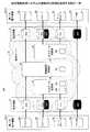
図1は、本実施形態の設定情報利用システムの概略的な処理を説明する図の一例である。図1では電子機器40として複合機が想定されている。以下、設定情報8をエクスポートする電子機器40を第一の電子機器40−1、設定情報8をインポートする電子機器40を第二の電子機器40−2という。<Outline of processing>
FIG. 1 is an example of a diagram illustrating a schematic process of the setting information utilization system of the present embodiment. In FIG. 1, a multifunction device is assumed as the
ハードウェア、ソフトウェア又は設計方針などの違いにより、第一の電子機器40−1と第二の電子機器40−2とでメモリ空間等が変更になっている場合がある。対応するはずの設定項目の記憶場所も両者で異なる可能性があり、現在ユーザが使用している第一の電子機器40−1の設定情報がそのまま(例えば同じアドレスに)新しい第二の電子機器40−2に移動された場合、第二の電子機器40−2が所望の動作を行えないおそれがある。 The memory space and the like may be changed between the first electronic device 40-1 and the second electronic device 40-2 due to differences in hardware, software, design policy, and the like. The storage location of the setting items that should correspond may also be different between the two, and the setting information of the first electronic device 40-1 currently used by the user remains as it is (for example, at the same address) as the new second electronic device. If moved to 40-2, the second electronic device 40-2 may not be able to perform the desired operation.
このため、変換サーバ30は第一の電子機器40−1のメモリ空間の調整等を行い、同じ設定項目同士を対応させ、更に、第二の電子機器40−2のメモリ空間の調整等を行った上で第二の電子機器40−2に設定情報を設定する。 Therefore, the
電子機器40は設定情報として、プリファレンス8a、メモリデータ8b、サービス設定データ8c、及びアドレス帳8d等を記憶している。これらの詳細は後述される。これらは設定情報の一例に過ぎず、設定情報はこの他にも存在する。設定情報の種類によって、適切な変換方法が異なるため変換サーバ30は設定情報の種類に応じて適切な変換方法で変換する。
・プリファレンス8a:プリファレンス8aはユーザが設定した設定値であるため、設定項目に対応付けて保存されている。このため、異機種間変換部33が第一の電子機器40−1と第二の電子機器40−2の設定項目の対応を考慮することで変換できる。メモリ空間は考慮されなくてよい。
・メモリデータ8b:メモリデータ8bは電子機器40で動作するモジュール(簡単にいうとアプリケーションなど一まとまりの機能)が使用する情報なので、意味のあるデータとして取得するには電子機器40の機種のメモリ空間にしたがって変換サーバ30が取得する必要がある。このため、入力データ変換部32が第一の電子機器40−1の機種に適したデータ形式変換テーブル39bを参照して設定項目ごとに設定値を取得する。更に、入力データ変換部32は第一の電子機器40−1の機種に適した異機種間変換テーブル39cを参照して、設定項目を機種に共通の形式に変更する(具体的には機種に共通の識別情報を付与する)。その後、異機種間変換部33が第二の電子機器40−2の機種に適した異機種間変換テーブル39cを参照して入力データ変換部32は第二の電子機器40−2の設定項目の識別情報を設定情報に付与する。更に、出力データ変換部34が第二の電子機器40−2の機種に適したデータ形式変換テーブル39bを参照して、各設定項目ごとに第二の電子機器40−2のメモリ空間等が考慮された記憶場所に設定値を配置する。
・サービス設定データ8c:メモリデータ8bと同様に電子機器40のメモリ空間にしたがって保持されているため、入力データ変換部32、異機種間変換部33、及び、出力データ変換部34の順に変換される。
・アドレス帳8d:アドレス帳8dは電子機器40の機種に依存しない情報である。例えば、第一の電子機器40−1の氏名は第二の電子機器40−2にとっても氏名である。このため、アドレス帳8dの変換は不要である。The
-
-
-
-
また、このように変換することで変換サーバ30のメモリデータ8b及びサービス設定データ8cをCE等が閲覧したり変更したりすることが可能になる。まず、プリファレンス8aの各設定項目がどのような設定項目であるかは電子機器40のメーカなどが管理しているため、第一の電子機器40から取得されたプリファレンス8aがどの設定項目で現在の設定が何であるかは明らかになっている。このため、CE(カスタマーエンジニア)又はユーザは変換サーバ30上のプリファレンス8aを確認したり変更したりすることができる。アドレス帳8dについては機種に依存しないため、言うまでもなくCE又はユーザが閲覧したり変更したりできる(アドレス帳8dが暗号化されていないか又は復号された場合)。 Further, by converting in this way, the
これに対し、メモリデータ8bとサービス設定データ8cは電子機器40の機種に依存するが、本実施形態ではデータ形式変換テーブル39bと異機種間変換テーブル39cとで変換されることで、設定項目ごとに電子機器40の機種に依存しない共通の形式に変換されている。このため、CE又はユーザは変換サーバ上のメモリデータ8b及びサービス設定データ8cを確認したり変更したりすることができる。 On the other hand, the
このように本実施形態の設定情報利用システム100は、メモリデータ8bやサービス設定データ8cなど従来は変換が困難であった設定情報も、変換サーバが一括して変換できるので、設定情報のインポート後のCE又はユーザの作業を軽減できる。また、メモリデータ8bやサービス設定データ8cが共通の形式に変換されるので、CE又はユーザがインポート前に閲覧したり変更したりすることができる。 As described above, in the setting
<用語について>
電子機器の設定に関する設定情報とは、電子機器に設定されている電子的な情報である。設定の経路、情報の内容、及び、管理する機能等によって様々である。設定情報は変換が不要な情報、設定項目の対応だけが異なる情報、又は、メモリ空間等が異なる情報に分けられる。<Terminology>
The setting information related to the setting of the electronic device is the electronic information set in the electronic device. It varies depending on the setting route, the content of information, the function to manage, and the like. The setting information is divided into information that does not need to be converted, information that differs only in correspondence of setting items, or information that differs in memory space and the like.
設定情報の設定項目は、それ自体で意味のある最小単位の情報である。設定値は設定項目に設定された値である。 The setting item of the setting information is the information of the smallest unit that is meaningful by itself. The set value is the value set in the setting item.
設定情報の形式とは、設定情報の態様がしたがう一定の様式、配置、読み出し方法など、設定情報を特徴づける共通して備えているかたちをいう。機種に共通の形式は、各機種から意味のある状態で取り出された形式であればよい。機種の違いに依存しないと称してもよい。 The format of the setting information refers to a form that is commonly provided to characterize the setting information, such as a certain format, arrangement, and reading method according to the mode of the setting information. The format common to all models may be a format extracted from each model in a meaningful state. It may be said that it does not depend on the model.
記憶に関する情報とは、設定値が記憶されている場所から取得するための情報である。例えば、記憶場所、データタイプ、レングス(設定値の長さ)、エンディアン(データの配置順)などである。 The information related to the memory is the information to be acquired from the place where the set value is stored. For example, storage location, data type, length (length of set value), endian (order of data arrangement), and the like.
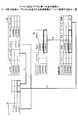
<システム構成例>
図2は、設定情報利用システム100の概略構成図の一例を示す。設定情報利用システム100は、ネットワークNを介して接続された複数の電子機器40、変換サーバ30、及び、設定端末60を有する。第一の電子機器40−1と第二の電子機器40−2には着脱可能な可搬性の記憶媒体9が装着され得る。<System configuration example>
FIG. 2 shows an example of a schematic configuration diagram of the setting
第一の電子機器40−1は、すでに設定項目に設定情報8が設定された電子機器40である。第二の電子機器40−2は、第一の電子機器40−1の設定情報8が設定される電子機器40である。第二の電子機器40−2は新たに購入された電子機器40である場合が多いが、第一の電子機器40−1の設定情報8が設定される任意の電子機器であっても差し支えない。第一の電子機器40−1が第二の電子機器40−2に切り替わる場合、又は、第一の電子機器40−1が使用されたまま第二の電子機器40−2が追加される場合のどちらでもよい。 The first electronic device 40-1 is an
第一の電子機器40−1及び第二の電子機器40−2はユーザがカスタマイズすることで使いやすくすることができる。カスタマイズとは標準の設定をユーザ自身の使い勝手に合わせて変えることをいう。すなわち、電子機器40はユーザが変更可能な設定情報8で動作する機器ということができる。ただし、後述するように設定情報8はユーザが設定する情報に限られず、CEが設定する情報、アプリケーションが管理する情報、印刷機能などのエンジンに関する情報などがある。 The first electronic device 40-1 and the second electronic device 40-2 can be easily used by being customized by the user. Customization means changing standard settings to suit the user's own convenience. That is, the
第一の電子機器40−1及び第二の電子機器40−2の具体例として、複合機、プロジェクタ、電子黒板、及びテレビ会議端末等があるがこれらに限るものではない。 Specific examples of the first electronic device 40-1 and the second electronic device 40-2 include, but are not limited to, a multifunction device, a projector, an electronic blackboard, a video conferencing terminal, and the like.
複合機は、多機能な周辺装置を意味し、例えば、プリンタ、スキャナ、及びFAXの送受信のうち複数の機能を有する。プリンタとスキャナの機能でコピー機能を実現したり、スキャナとFAXの送信機能で画像を送信したりプリンタとFAXの受信機能で画像を受信したりする。複合機は、画像形成装置、画像処理装置、プリンタ装置、複写機、MFP(Multi-function Peripherals)などと呼ばれる場合がある。 A multifunction device means a multifunctional peripheral device, and has, for example, a plurality of functions of transmitting and receiving a printer, a scanner, and a fax machine. The copy function is realized by the function of the printer and the scanner, the image is transmitted by the transmission function of the scanner and the FAX, and the image is received by the reception function of the printer and the FAX. The multifunction device may be referred to as an image forming apparatus, an image processing apparatus, a printer apparatus, a copying machine, an MFP (Multi-function Peripherals), or the like.
プロジェクタは画像を投影する投影機である。あるいは映写機と呼ばれる場合がある。電子黒板は電子ペン又は指などの指示手段が指示する座標を検出し、座標を連結したストロークをディスプレイに表示する。電子黒板は、電子情報ボード、電子ホワイトボードなどと呼ばれる場合がある。テレビ会議端末は、異なる拠点間で画像データ及び音声データの送受信を行い、ディスプレイに画像を表示したり、スピーカから音声を出力したりすることで、テレビ会議端末を使用する参加者がテレビ会議を行うことを可能にする。 A projector is a projector that projects an image. Alternatively, it may be called a projector. The electronic blackboard detects the coordinates indicated by the pointing means such as an electronic pen or a finger, and displays the stroke in which the coordinates are connected on the display. The electronic blackboard may be called an electronic information board, an electronic whiteboard, or the like. The video conferencing terminal sends and receives image data and audio data between different bases, displays the image on the display, and outputs the audio from the speaker, so that the participants who use the video conferencing terminal can hold a video conference. Allows you to do.
この他、電子機器40はデジタルサイネージ、デジタルカメラ、又はドローンなど、設定情報8がカスタマイズされる機器でよい。 In addition, the
ネットワークNは、電子機器40が設置された場所に敷設されているLAN、LANをインターネットに接続するプロバイダのプロバイダネットワーク、及び、回線事業者が提供する回線等により構築されている。ネットワークNが複数のLANを有する場合、ネットワークNはWANと呼ばれる。また、コンピュータを世界的な規模で接続すると共に世界中のネットワークが相互接続されたインターネットが含まれる。 The network N is constructed by a LAN installed at a place where the
ネットワークNは有線又は無線のどちらで構築されてもよく、また、有線と無線が組み合わされていてもよい。また、電子機器40が直接、公衆回線網に接続する場合は、LANを介さずにプロバイダネットワークに接続することができる。無線で接続する場合にはWi-Fi(登録商標)、Bluetooth(登録商標)、3G、4G、LTEなどの通信規格が適宜使用される。 The network N may be constructed either wired or wireless, and may be a combination of wired and wireless. Further, when the
設定端末60は、CE又はユーザが第一の電子機器40−1と第二の電子機器40−2を変換サーバ30に対し指定したり、第一の電子機器40−1から変換サーバ30に送信された設定情報を閲覧及び/又は変更したりするためなどに使用される。また、CE又はユーザが記憶媒体9の設定情報8を変換サーバ30に送信したり、変換サーバ30から変換後の設定情報8を受信したりするために使用される。変換とは、第一の電子機器40−1の設定情報8の形式を第二の電子機器40−2に適した形式の設定情報8に変換することを言う。設定端末60は、ブラウザソフトウェア又はこれと同等のアプリケーションが動作すればよい。設定端末60は、例えばPC(Personal Computer)、スマートフォン、タブレット端末、携帯電話、PDA(Personal Data Assistant)、ゲーム機、カーナビゲーション、などであるがこれらに限られない。 In the setting
変換サーバ30は、第一の電子機器40−1の形式の設定情報8を第二の電子機器40−2の形式の設定情報8に変換する情報処理装置である。変換方法の詳細は後述される。なお、変換サーバ30はクラウドコンピューティングに対応していることが好ましい。クラウドコンピューティングとは、特定ハードウェア資源が意識されずにネットワーク上のリソースが利用される利用形態をいう。 The
<ハードウェア構成例>
<<電子機器>>
図3は、電子機器40のハードウェア構成の一例を示す図である。図3に示すように、電子機器は、本体10と、操作部20と、を備える。本体10と操作部20は、専用の通信路300を介して相互に通信可能に接続されている。通信路300は、例えばUSB(Universal Serial Bus)規格のものを用いることもできるが、有線か無線かを問わず任意の規格のものであってよい。<Hardware configuration example>
<< Electronic equipment >>
FIG. 3 is a diagram showing an example of the hardware configuration of the
なお、本体10は、操作部20で受け付けた操作に応じた動作を行うことができる。また、本体10は、クライアントPC(パーソナルコンピュータ)等の外部装置とも通信可能であり、外部装置から受信した指示に応じた動作を行うこともできる。 The
次に、本体10のハードウェア構成について説明する。図3に示すように、本体10は、CPU(Central Processing Unit)11と、ROM(Read Only Memory)12と、RAM(Random Access Memory)13と、HDD(Hard Disk Drive)14と、通信I/F(Interface)15と、接続I/F16と、エンジン部17とを備え、これらがシステムバス18を介して相互に接続されている。説明の便宜上、図3では、本体10はHDD14を有している構成を例に挙げて説明したが、例えばHDD14を有しておらず、十分な記憶領域を確保できない構成もあり得る。 Next, the hardware configuration of the
CPU11は、本体10の動作を統括的に制御する。CPU11は、RAM13をワークエリア(作業領域)としてROM12又はHDD14等に格納されたプログラムを実行することで、本体10全体の動作を制御し、上記したコピー機能、スキャナ機能、ファクス機能、プリンタ機能などの各種機能を実現する。 The CPU 11 comprehensively controls the operation of the
通信I/F15は、ネットワークNと接続するためのインタフェースである。接続I/F16は、通信路300を介して操作部20と通信するためのインタフェースである。 The communication I /
エンジン部17は、コピー機能、スキャナ機能、ファクス機能、及び、プリンタ機能を実現させるための、汎用的な情報処理及び通信以外の処理を行うハードウェアである。例えば、原稿の画像をスキャンして読み取るスキャナ(画像読取部)、用紙等のシート材への印刷を行うプロッタ(画像形成部)、ファクス通信を行うファクス部などを備えている。更に、印刷済みシート材を仕分けるフィニッシャや、原稿を自動給送するADF(自動原稿給送装置)のような特定のオプションを備えることもできる。 The engine unit 17 is hardware that performs general-purpose information processing and processing other than communication in order to realize a copy function, a scanner function, a fax function, and a printer function. For example, it is provided with a scanner (image reading unit) that scans and reads an image of a document, a plotter (image forming unit) that prints on a sheet material such as paper, and a fax unit that performs fax communication. Further, it may be provided with specific options such as a finisher for sorting printed sheet materials and an ADF (automatic document feeder) that automatically feeds documents.
次に、操作部20のハードウェア構成について説明する。図3に示すように、操作部20は、CPU21と、ROM22と、RAM23と、フラッシュメモリ24と、通信I/F25と、接続I/F26と、操作パネル27、外部接続I/F29とを備え、これらがシステムバス28を介して相互に接続されている。説明の便宜上、図3では、操作部20はフラッシュメモリ24を有している構成を例に挙げて説明したが、例えばフラッシュメモリ24を有していない構成もあり得る。要するに、電子機器は、大容量のデータを記憶するための記憶装置を有していない構成もあり得る。 Next, the hardware configuration of the
記憶媒体9は不揮発性の記憶装置である。上記のように着脱可能で可搬性があることが好ましい。例えばSDメモリーカード(登録商標)、USBメモリ、コンパクトフラッシュ(登録商標)、HDD、SSD(Solid State Drive)などがある。第一の電子機器40−1及び第二の電子機器40−2が情報を書き込んだり情報を読み出したりできればどのような記憶媒体でもよい。 The
<<変換サーバ>>
図4は、変換サーバ30のハードウェア構成図の一例である。変換サーバ30は、CPU301と、ROM302と、RAM303と、通信I/F304と、入力装置305と、表示装置306とを備える。CPU301は、変換サーバ30の動作を統括的に制御する。ROM302は、プログラム等の各種のデータを記憶する不揮発性のメモリである。RAM303は、CPU301が実行する各種の処理の作業領域(ワークエリア)として機能する揮発性のメモリである。通信I/F304は、ネットワークNと接続するためのインタフェースである。入力装置305は、ユーザによる操作の入力に用いられるデバイスであり、例えばマウスやキーボードなどで構成される。表示装置306は各種の情報を表示するデバイスであり、例えば液晶型ディスプレイ装置などで構成される。<< Conversion server >>
FIG. 4 is an example of a hardware configuration diagram of the
設定端末60のハードウェア構成は変換サーバ30と同じであるか、又は異なっていても本実施形態の説明に支障はないものとする。 Even if the hardware configuration of the setting
上記のように、変換サーバ30はクラウドコンピューティングに対応していることが好ましい。したがって、図示したハードウェア構成は、1つの筐体に収納されていたりひとまとまりの装置として備えられていたりする必要はなく、変換サーバ30が備えていることが好ましいハード的な要素を示す。また、クラウドコンピューティングに対応するため、本実施例の変換サーバ30の物理的な構成は固定的でなくてもよく、負荷に応じてハード的なリソースが動的に接続・切断されることで構成されてよい。 As described above, it is preferable that the
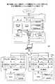
<機能について>
図5は、電子機器40、及び、変換サーバ30の機能をブロック状に説明する設定情報利用システム100の機能ブロック図の一例である。図5は電子機器40が変換サーバ30に設定情報8を送信するパターンにおいて使用される機能ブロック図を示す。<About functions>
FIG. 5 is an example of a functional block diagram of the setting
第一の電子機器40−1と第二の電子機器40−2の機能は同一であるか、又は、異なっていても本実施形態の説明においては支障がないものとする。このため、主に第一の電子機器40−1について説明する。 Even if the functions of the first electronic device 40-1 and the second electronic device 40-2 are the same or different, there is no problem in the description of the present embodiment. Therefore, the first electronic device 40-1 will be mainly described.
<<第一の電子機器40−1、第二の電子機器40−2>>
第一の電子機器40−1は表示・操作部41、設定データ送信部42、設定データ受信部43、設定データ取得部44、設定データ設定部45、及び、基本機能部46を有している。まず、表示・操作部41は主に操作部20により実現されている。表示・操作部41は、図3に示された各構成要素のいずれかが、フラッシュメモリ24からRAM23に展開されたプログラムに従ったCPU21からの命令により動作することで実現される機能又は手段である。このプログラムは、プログラム配信用のサーバから配信されるか又は記憶媒体9に記憶された状態で配布される。<< First electronic device 40-1, Second electronic device 40-2 >>
The first electronic device 40-1 has a display /
一方、設定データ送信部42、設定データ受信部43、設定データ取得部44、設定データ設定部45、及び、基本機能部46は、図3に示された各構成要素のいずれかが、HDD14からRAM13に展開されたプログラムに従ったCPU11からの命令により動作することで実現される機能又は手段である。このプログラムは、プログラム配信用のサーバから配信されるか又は記憶媒体9に記憶された状態で配布される。ただし、これら機能は本体10と操作部20のどちらにあってもよい。 On the other hand, in the setting
表示・操作部41は操作パネル27に各種の画面を表示したり、CE又はユーザの操作を受け付けたりする。 The display /
基本機能部46は、第一の電子機器40−1が持っている基本的な機能である。第一の電子機器40−1が複合機の場合、印刷、原稿の読み取り、FAX送受信などの機能を提供する。また、基本機能部46は機種別プロファイル7に基づいて記憶部49から設定情報8を取得したり書き込んだりする。基本機能部46はCPU11がプログラムを実行しエンジン部17を制御すること等により実現される。基本機能部46の機能を図6にて説明する。 The
設定データ取得部44は、基本機能部46から設定情報8を取得する。主に、第一の電子機器40−1で使用される機能である。設定データ取得部44は、CPU11がプログラムを実行すること等により実現される。また、設定データ取得部44は設定情報8のうち機種別プロファイル7が指定する設定項目の設定値を暗号化する。 The setting
設定データ送信部42は、設定データ取得部44が取得した設定情報8をネットワーク経由で変換サーバ30に送信する。主に第一の電子機器40−1で使用される機能である。CPU11がプログラムを実行し通信I/F15を制御すること等により実現される。 The setting
設定データ受信部43は、変換サーバ30からネットワーク経由で設定情報8を受信し、設定データ設定部45に送出する。主に第二の電子機器40−2で使用される機能である。設定データ受信部43はCPU11がプログラムを実行し通信I/F15を制御すること等により実現される。 The setting
設定データ設定部45は、設定データ受信部43が受信した設定情報8を基本機能部46に送出する。主に第二の電子機器40−2で使用される機能である。また、設定データ設定部45は設定情報8のうち機種別プロファイル7が指定する設定項目の設定値を復号する。設定データ設定部45はCPU11がプログラムを実行すること等により実現される
また、第一の電子機器40−1は記憶部49を有している。記憶部49は、本体10のHDD14、RAM13及びROM12の1つ以上により実現される情報の記憶手段である。記憶部49には、設定情報8の他、機種別プロファイル7、プログラム、文書、及びログ情報等が記憶される。The setting

モジュールIDはモジュールを識別するための識別情報であり、プリファレンスIDはプリファレンスを識別するための識別情報である。IDはIdentificationの略であり識別子や識別情報という意味である。IDは複数の対象から、ある特定の対象を一意的に区別するために用いられる名称、符号、文字列、数値又はこれらのうち1つ以上の組み合わせをいう。他のIDについても同様である。取得可否はプリファレンスIDで指定される設定項目が設定情報8に含まれるか否かを指示する。例えば、カウンタ情報(第一の電子機器40−1が過去に何ページ印刷したかを示す)は第二の電子機器40−2では使用されないので取得されない。また、機器ID(電子機器の識別情報)は第二の電子機器40−2に設定されると機器が入れ替わったと判断されるおそれがあるので取得されない。暗号可否はプリファレンスIDで指定される設定項目を暗号化するか否かを指定する。暗号化されるのは秘匿性が高い設定項目である。例えば、管理者のパスワード(メモリデータ8b内にある)、及び、アドレス帳8dなどである。 The module ID is the identification information for identifying the module, and the preference ID is the identification information for identifying the preference. ID is an abbreviation for Identification and means an identifier or identification information. An ID refers to a name, a code, a character string, a numerical value, or a combination of one or more of these, which is used to uniquely distinguish a specific object from a plurality of objects. The same applies to other IDs. Whether or not the acquisition is possible indicates whether or not the setting item specified by the preference ID is included in the setting
なお、この機種別プロファイル7は変換サーバ30から配信されてもよいし、記憶媒体9から第一の電子機器40−1が読み取ってもよい。 The model-specific profile 7 may be distributed from the
<<変換サーバ>>
変換サーバ30は設定データ入出力部31、入力データ変換部32、異機種間変換部33、出力データ変換部34、及び、UI部35を有している。変換サーバ30が有するこれら各機能部は、図4に示された各構成要素のいずれかが、HDD307からRAM303に展開されたプログラムに従ったCPU301からの命令により動作することで実現される機能又は手段である。このプログラムは、プログラム配信用のサーバから配信されるか又は記憶媒体9に記憶された状態で配布される。<< Conversion server >>
The
設定データ入出力部31は第一の電子機器40−1及び第二の電子機器40−2との間で設定情報8を送受信する。通信プロトコルにHTTs又はHTTP2.0など暗号通信が用いられる。設定データ入出力部31は、図4のCPU301がプログラムを実行し通信I/F304を制御すること等により実現される。 The setting data input /
入力データ変換部32は、テーブル記憶部39に記憶された第一の電子機器40−1の機種に適したデータ形式変換テーブル39b及び第一の電子機器40−1の機種に適した異機種間変換テーブル39cを参照して第一の電子機器40−1の設定情報8を機種に共通の形式に変換する。 The input
異機種間変換部33は、入力データ変換部32が変換した変換結果(すなわち設定情報)の設定項目を、第二の電子機器40−2の機種に適した異機種間変換テーブル39cを参照して、第二の電子機器40−2の設定項目と対応付ける。 The
出力データ変換部34は、異機種間変換部33が第二の電子機器40−2の設定項目と対応付けた設定情報を、テーブル記憶部39に記憶された第二の電子機器40−2の機種に適したデータ形式変換テーブル39bを参照して、第二の電子機器40−2のメモリ空間等にしたがって配置する。 In the output
入力データ変換部32、異機種間変換部33及び出力データ変換部34は図4のCPU301がプログラムを実行すること等により実現される。 The input
入力データ変換部32、異機種間変換部33及び出力データ変換部34の3つで変換されるのは主にメモリデータ8bとサービス設定データ8cであり、プリファレンス8aは異機種間変換部33で設定項目が対応付けられればよく、アドレス帳8dは変換されない。 The input
UI部35は、設定端末60とHTTPsなどの通信プロトコルで通信し、HTML及びJavaScript(登録商標)などで記述された画面情報を設定端末60に送信するHTTPサーバの機能を提供する。UI部35は、図4のCPU301がプログラムを実行すること等により実現される。 The
また、変換サーバ30は設定情報記憶部38とテーブル記憶部39を有している。設定情報記憶部38とテーブル記憶部39は、図4のHDD307、RAM303及びROM302の1つ以上により実現される情報の記憶手段である。設定情報記憶部38には、第一の電子機器40−1から送信された設定情報8とこれを管理する設定情報管理テーブルが記憶される。また、テーブル記憶部39には、ユーザ情報管理テーブル39a、データ形式変換テーブル39b、及び、異機種間変換テーブル39c等が記憶される。 Further, the
エリアID:情報の所在を示しており、例えば、RAM13若しくはRAM23における設定値の記憶場所、レジスタなどにおける記憶場所、又はその他の記憶場所を示す。記憶場所が決まれば取得方法も決定される。 Area ID: Indicates the location of information, for example, a storage location of a set value in a
データタイプ:データ型を識別する識別情報である。データタイプの詳細を表4に示す。 Data type: Identification information that identifies the data type. Details of the data types are shown in Table 4.
レングス:設定項目の設定値の長さ(データサイズ)を示す。 Length: Indicates the length (data size) of the set value of the setting item.
オフセット:エリアIDで指定されるアドレスの先頭を基準にして設定値までのアドレスの差分を示す。 Offset: Indicates the difference between the addresses up to the set value with reference to the beginning of the address specified by the area ID.
モジュールIDとプリファレンスIDは表2と同様の情報である。モジュールIDにより機能が特定され、プリファレンスIDによりモジュール内の設定項目が特定されるので、モジュールIDとプリファレンスIDは電子機器40における設定項目の識別情報となる。モジュールIDはモジュールの識別情報であり、プリファレンスIDにはそのモジュールにおける識別情報である。 The module ID and preference ID are the same information as in Table 2. Since the function is specified by the module ID and the setting items in the module are specified by the preference ID, the module ID and the preference ID are identification information of the setting items in the
表3のデータ形式変換テーブル39bによれば、モジュールIDとプリファレンスIDにより電子機器40の各設定項目が一意に特定され、設定項目がどこに記憶されているかがエリアIDにより特定される。そして、エリアIDで指定されるエリアのどこからどこまでに設定値が記憶されているかが、オフセットとレングスにより特定される。設定項目のデータタイプも分かるので電子機器40で表現されていたデータを電子機器40と同様に解釈する方法が判明する。データ形式変換テーブル39bは変換サーバ30が有するだけでなく各電子機器40が有することが好ましい。図19で説明するように暗号化された情報を電子機器40が復号して再配置する際に使用される場合があるためである。 According to the data format conversion table 39b in Table 3, each setting item of the
また、異機種間変換テーブル39cは機種ごとに用意されるため、第一の電子機器40−1のモジュールIDとプリファレンスIDが共通ID1,2に対応付けられ、この共通ID1,2が第二の電子機器40−2のモジュールIDとプリファレンスIDに対応付けられる。したがって、第一の電子機器40−1のモジュールIDとプリファレンスIDが第二の電子機器40−2のモジュールIDとプリファレンスIDに対応付けられる。 Further, since the inter-model conversion table 39c is prepared for each model, the module ID and the preference ID of the first electronic device 40-1 are associated with the
<<基本機能部の機能>>
図6は、基本機能部46の機能をブロック状に示す機能ブロック図の一例である。基本機能部46は、設定情報の取得時機能と設定時機能を有する。取得時機能はエクスポート部46a、サービス設定データリード部46b、メモリリード部46c、及び、API(Application Interface)46dを有する。それぞれのブロックは記憶部49の設定情報のうち対応する種類の設定情報を取得する。エクスポート部46aはプリファレンス8aを記憶部49から取得する。メモリリード部46cはメモリデータ8bを記憶部49から取得する。サービス設定データリード部46bはサービス設定データ8cを記憶部49から取得する。API46dはアドレス帳8dを記憶部49から取得する。なお、APIとは基本機能部46がアプリケーションに処理を要求し処理結果を取得するためのインタフェース(アプリケーションを呼び出すための関数)である。設定情報にはアプリケーションが管理するものもあり、このような設定情報はアプリケーションを介して取得及び設定される。<< Functions of basic functions >>
FIG. 6 is an example of a functional block diagram showing the functions of the basic
設定時機能はインポート部46e、サービス設定データライト部46f、メモリライト部46g、及び、API46dを有する。それぞれのブロックは記憶部49の設定情報8のうち対応する種類の設定情報8を記憶部49に書き込む。インポート部46eはプリファレンス8aを記憶部49に書き込む。メモリライト部46gはメモリデータ8bを記憶部49に書き込む。サービス設定データライト部46fはサービス設定データ8cを記憶部49に書き込む。API46dはアドレス帳8dを記憶部49に書き込む。 The setting function includes an
<記憶媒体に設定される場合の構成>
図7は、電子機器40、及び、変換サーバ30の機能をブロック状に説明する設定情報利用システム100の機能ブロック図の一例である。図7は電子機器40が記憶媒体9に設定情報8を書き込むパターンにおいて使用される機能ブロック図である。図7の説明では主に図5との相違を説明する。<Configuration when set as storage medium>
FIG. 7 is an example of a functional block diagram of the setting
図7では第一の電子機器40−1と第二の電子機器40−2が設定データ書込部47と設定データ読出部48を有している。設定データ書込部47は、記憶媒体9に設定情報8を書き込む。主に第一の電子機器40−1で使用される機能である。設定データ読出部48は記憶媒体9から設定情報8を読み出す。主に第二の電子機器40−2で使用される機能である。設定データ書込部47と設定データ読出部48は、CPU11がプログラムを実行し外部接続I/F29を制御すること等により実現される。 In FIG. 7, the first electronic device 40-1 and the second electronic device 40-2 have a setting
図7の構成では、設定端末60が記憶媒体9に記憶された設定情報8を変換サーバ30に送信し、変換サーバ30から変換後の設定情報8を受信して記憶媒体9に記憶させる。したがって、変換サーバ30の機能は同様でよい。 In the configuration of FIG. 7, the setting
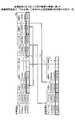
<設定情報8の設定パターン>
図8は設定情報利用システム100において設定情報8が設定されるパターンを説明する図の一例である。
パターン1:第一の電子機器40−1→変換サーバ30→第二の電子機器40−2
パターン2:第一の電子機器40−1→記憶媒体9→設定端末60→変換サーバ30→設定端末60→記憶媒体9→第二の電子機器40−2
パターン3:第一の電子機器40−1→変換サーバ30→設定端末60→記憶媒体9→第二の電子機器40−2
パターン4:第一の電子機器40−1→記憶媒体9→設定端末60→変換サーバ30→第二の電子機器40−2
主に使用されるパターンはパターン1又はパターン2である。CE又はユーザは十分な通信帯域を確保できないネットワーク環境である場合や、変換サーバ30に設定情報8が保持されることが社内規定などで禁止される場合などは、パターン2を選択する。また、アドレス帳8dが膨大であるなどの理由で変換サーバ30への送信時間が長くなることが予想される場合にもパターン2を選択する。それ以外はパターン1を選択すればよい。<Setting pattern of setting
FIG. 8 is an example of a diagram for explaining a pattern in which the setting
Pattern 1: First electronic device 40-1
Pattern 2: First electronic device 40-1
Pattern 3: First electronic device 40-1
Pattern 4: First electronic device 40-1
The pattern mainly used is
また、エクスポート時とインポート時で状況が変わったような場合は、パターン3やパターン4を選択することもできる。 Further, if the situation changes between the time of export and the time of import,
また、エクスポートやインポートにおいて、本実施形態では記憶媒体9に設定情報8が記憶されているが、第一の電子機器40−1が直接、設定端末60に設定情報8を送信してもよいし、第二の電子機器40−2が設定端末60から直接、設定情報8を受信してもよい。 Further, in the export or import, the setting
<変換の具体例>
次に、図9〜11を用いてデータ形式変換テーブル39b及び異機種間変換テーブル39cによる設定情報の変換を説明する。<Specific example of conversion>
Next, the conversion of the setting information by the data format conversion table 39b and the heterogeneous conversion table 39c will be described with reference to FIGS. 9 to 11.
図9は、入力データ変換部32が第一の電子機器40−1の機種に適したデータ形式変換テーブル39bと異機種間変換テーブル39cを用いて、第一の電子機器40−1の設定情報を機種に共通の設定情報に変換する処理を模式的に説明する図である。図9では、メモリデータ8bの変換例を説明する。サービス設定データ8cの変換も同様になる(詳細を図17,18にて説明する)。図9のメモリデータ8bは例えばバイナリデータである。設定情報の所在がエリアIDで特定され、オフセットで設定値の先頭が特定され、データサイズでどこまでが1つの設定値か特定され、データタイプにより解釈方法が特定される。 In FIG. 9, the input
(i) 入力データ変換部32は、第一の電子機器40−1の機種に適したデータ形式変換テーブル39bを参照し任意のモジュールIDとプリファレンスIDを決定する。 このモジュールIDとプリファレンスIDに対応付けられたエリアIDによりメモリデータ8bの記憶場所を特定する。 (i) The input
(ii) メモリデータ8bの先頭からデータ形式変換テーブル39bのオフセット分を移動し、データタイプにしたがってレングス分を1つの設定値として読み取る。 (ii) The offset portion of the data format conversion table 39b is moved from the beginning of the
(iii) 第一の電子機器40−1の機種に適した異機種間変換テーブル39cを参照してモジュールIDとプリファレンスIDに対応付けられた共通ID1,2を読み出す。 (iii) The
(iv) メモリデータ8bから読み取った設定値、モジュールIDとプリファレンスID、共通ID1,2、及び、データタイプ、を変換結果Aとして生成する。 (iv) The set value read from the
図9のメモリデータ8bには「A」「B」「C」「D」「E」「F」という文字が記載されている。「A」「B」「C」「D」「E」「F」はこの文字を表すわけではなくそれぞれが1つの設定値である。また、「A」「C」「D」「E」が反転しているのは、機種別プロファイル7により取得されたことを意味している。換言すると「B」「F」はカウンタ情報などであるため取得されない。 The characters "A", "B", "C", "D", "E", and "F" are described in the
以上のような処理により、図9の変換結果Aに示すように、モジュールID、プリファレンスID、共通ID1,2、データタイプ、及び、設定値が対応付けられる。変換結果Aは、第一の電子機器40−1の設定値が内容(共通ID1,2)及び解釈方法(データタイプ)と共に取得されているため、例えば設定端末60から閲覧可能な機種に共通の形式の設定情報である。 By the above processing, as shown in the conversion result A of FIG. 9, the module ID, the preference ID, the
図10は変換結果A及び第二の電子機器40−2の機種に適した異機種間変換テーブル39cを用いて作成される変換結果Bを説明する図の一例である。変換結果Bは変換結果Aが第二の電子機器40−2と結びつけられた設定情報である。 FIG. 10 is an example of a diagram for explaining the conversion result A and the conversion result B created by using the heterogeneous conversion table 39c suitable for the model of the second electronic device 40-2. The conversion result B is the setting information in which the conversion result A is associated with the second electronic device 40-2.
(i) 異機種間変換部33は変換結果Aの共通ID1、2と同じ共通ID1,2を第二の電子機器40−2の機種に適した異機種間変換テーブル39cから検索する。 (i) The
(ii) 第二の電子機器40−2の機種に適した異機種間変換テーブル39cの共通ID1、2に対応付けられたモジュールIDとプリファレンスIDを読み出す。 (ii) Read out the module ID and the preference ID associated with the
(iii) 第二の電子機器40−2の機種に適した異機種間変換テーブル39cの共通ID1,2をそれぞれ読み出す。 (iii) The
(iv) 変換結果Aから共通ID1,2に対応付けられたデータタイプと設定値を読み出す。第二の電子機器40−2の機種に適した異機種間変換テーブル39cのモジュールIDとプリファレンスID、共通ID1,2、変換結果Aの設定値及びデータタイプを対応付けて変換結果Bを生成する。 (iv) Read the data type and set value associated with the
この変換結果Bにより、第一の電子機器40−1の設定情報8の各設定項目が第二の電子機器40−2の設定項目と対応付けられた。なお、変換結果Bも機種に依存しない共通の形式の設定情報ということができる。 According to this conversion result B, each setting item of the setting
図11は、第二の電子機器40−2の機種に適したデータ形式変換テーブル39bを用いて変換結果Bから変換される第二の電子機器40−2の形式の設定情報8を説明する図である。 FIG. 11 is a diagram illustrating setting
(i) 出力データ変換部34は変換結果BのモジュールIDとプリファレンスIDを第二の電子機器40−2の機種に適したデータ形式変換テーブル39bから検索する。 (i) The output
(ii) 第二の電子機器40−2の機種に適したデータ形式変換テーブル39bのモジュールIDとプリファレンスIDに対応付けられたエリアIDによりメモリデータ8bの記憶場所を特定する。 (ii) The storage location of the
(iii)第二の電子機器40−2の機種に適したデータ形式変換テーブル39bのオフセット分をメモリデータ8bの先頭から移動し、レングス分の設定値をデータタイプにしたがって配置する。 (iii) The offset portion of the data format conversion table 39b suitable for the model of the second electronic device 40-2 is moved from the beginning of the
図11の例では、モジュールID「0x10000005」かつプリファレンスID「0x1000000B」の設定値「A」が、エリアIDが「0x00000005」の先頭からオフセット「0x00000030」の位置に1バイトで書き込まれている。図11と図9のメモリデータ8bを比較すると、設定値「A」が格納される場所が変更されている。 In the example of FIG. 11, the set value "A" of the module ID "0x10000005" and the preference ID "0x1000000B" is written in 1 byte at the position of the offset "0x000000030" from the beginning of the area ID "0x00000005". Comparing the
以上のようにして、第一の電子機器40−1の形式の設定情報が共通の設定情報に変更され、第二の電子機器40−2の形式の設定情報に変更される。したがって、本実施形態の変換サーバ30は、第一の電子機器40−1の設定情報8と第二の電子機器40−2の設定情報8とでメモリ空間、記憶場所、及びデータタイプなどが変更されていても、メモリデータ8bやサービス設定データ8cを第二の電子機器40−2の形式に変換できる。したがって、設定情報8のインポート後のCE又はユーザの作業負担を低減できる。 As described above, the setting information in the format of the first electronic device 40-1 is changed to the common setting information, and the setting information in the format of the second electronic device 40-2 is changed. Therefore, in the
<動作手順>
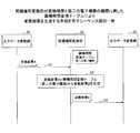
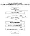
以下、設定情報利用システム100の各フェーズの全体的な動作について説明する。以下では、パターン1の場合の動作を説明する。<Operation procedure>
Hereinafter, the overall operation of each phase of the setting
<<エクスポート>>
図12は、第一の電子機器40−1が設定情報8を変換サーバ30に送信する手順を示すシーケンス図の一例である。<< Export >>
FIG. 12 is an example of a sequence diagram showing a procedure in which the first electronic device 40-1 transmits the setting
S1:第一の電子機器40−1の表示・操作部41はCE又はユーザからログインIDとパスワードを受け付け、設定データ送信部42がログイン要求を変換サーバ30に送信する。本実施形態ではログインできたものとする。 S1: The display /
S2:次に、第一の電子機器40−1の設定データ取得部44は設定情報8を基本機能部46から取得し、設定データ送信部42が機器IDと共に変換サーバ30に送信する。 S2: Next, the setting
S3:変換サーバ30の設定データ入出力部31は機器IDと設定情報8を受信し、設定情報記憶部38に機器IDと設定情報8を対応付けて保存する。なお、タイムスタンプは設定情報8のメタデータとして添付されており、コメントはCE又はユーザに任意に設定する。機器IDにより少なくとも機種の特定が可能になる。 S3: The setting data input /
<<変換処理>>
以下、図13〜図15を用いて設定情報利用システム100による設定情報8の変換の手順を説明する。<< Conversion process >>
Hereinafter, the procedure for converting the setting
図13は、第一の電子機器40−1の設定情報8から変換結果Aが生成される処理を示すシーケンス図の一例である。設定情報8は第一の電子機器40−1から変換サーバ30にすでに送信されている。 FIG. 13 is an example of a sequence diagram showing a process in which the conversion result A is generated from the setting
S1:CE又はユーザが設定端末60を操作して、第一の電子機器40−1の設定情報8を第二の電子機器40−2の設定情報8に変換するための指示をUI部35に対し行う。UI部35は異機種間変換部33にその旨を通知する。少なくとも第一の電子機器40−1と第二の電子機器40−2の機種がCE又はユーザにより指示される。機器ID等から特定されてもよい。 S1: The CE or the user operates the setting
S2:異機種間変換部33は、テーブル記憶部39に記憶された第一の電子機器40−1の機種に適したデータ形式変換テーブル39b及び異機種間変換テーブル39cを読みだし、入力データ変換部32に送出する。 S2: The
S3:入力データ変換部32は第一の電子機器40−1の機種に適したデータ形式変換テーブル39bと異機種間変換テーブル39cを参照し、設定項目ごとに設定情報8から設定値を読み出す。 S3: The input
S4:入力データ変換部32は図9で説明したように、第一の電子機器40−1の機種に適したデータ形式変換テーブル39bのモジュールIDとプリファレンスID、エリアID、オフセット、データタイプを取得し、これらに基づいて設定値を読みだし、異機種間変換テーブルの共通ID1,2を取得して、変換結果Aを生成する。 S4: As described with reference to FIG. 9, the input
入力データ変換部32は第一の電子機器40−1の機種に適したデータ形式変換テーブル39bのすべての設定項目が完了するまで繰り返し処理を行い、変換結果Aを生成する。 The input
図14は、異機種間変換部33が変換結果Aと第二の電子機器40−2の機種に適した異機種間変換テーブル39cにより変換結果Bを生成する手順を示すシーケンス図の一例である。 FIG. 14 is an example of a sequence diagram showing a procedure in which the
S1:異機種間変換部33は変換結果Aを入力データ変換部32から取得する。 S1: The
S2:異機種間変換部33は図10にて説明したように、変換結果Aのデータタイプと設定値、第二の電子機器40−2の異機種間変換テーブル39cのモジュールID、プリファレンスID、及び、共通ID1,2と対応付けた変換結果Bを生成する。 S2: As described with reference to FIG. 10, the
S3:異機種間変換部33は変換結果Bを出力データ変換部34に送出する。 S3: The
図15は、出力データ変換部34が変換結果Bと第二の電子機器40−2の機種に適したデータ形式変換テーブル39bを用いて、第二の電子機器40−2の形式の設定情報8を生成する手順を示すシーケンス図の一例である。 In FIG. 15, the output
S1:異機種間変換部33は変換結果Bを出力データ変換部34に送出する。 S1: The
S2:出力データ変換部34は、変換結果BのモジュールIDとプリファレンスIDで特定される第二の電子機器40−2の機種に適したデータ形式変換テーブル39bのエリアID、オフセットを読みだし、これらで指示された記憶場所に変換結果Bの設定値をデータタイプとレングスで配置する。 S2: The output
以上により、変換サーバ30では第一の電子機器40−1の設定情報8が第二の電子機器40−2に変換され、設定情報記憶部38に機器IDと対応付けられた状態で保持される。 As described above, in the
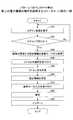
<<インポート>>
図16は、第二の電子機器40−2が変換サーバ30から設定情報8をインポートする手順を示すシーケンス図の一例である。<< Import >>
FIG. 16 is an example of a sequence diagram showing a procedure in which the second electronic device 40-2 imports the setting
S1:第二の電子機器40−2の表示・操作部41はCE又はユーザからログインIDとパスワードを受け付け、設定データ送信部42がログイン要求を送信する。本実施形態ではログインできたものとする。 S1: The display /
S2:変換サーバ30の設定データ入出力部31は、ユーザ情報管理テーブルでログインした顧客の機器IDを特定し、設定情報管理テーブルからこの機器IDに対応付けられた設定情報の一覧(ファイル名)を第二の電子機器40−2に送信する。 S2: The setting data input /
S3:第二の電子機器40−2の表示・操作部41はCE又はユーザからインポートする設定情報(ファイル)の選択を受け付ける。 S3: The display /
S4:第二の電子機器40−2の設定データ送信部42は選択されたファイル名を変換サーバ30に送信する。 S4: The setting
S5,S6:変換サーバ30の設定データ入出力部31は設定情報記憶部38から設定情報8を読み出す。 S5, S6: The setting data input /
S7:変換サーバ30の設定データ入出力部31は読み出した設定情報8を第二の電子機器40−2に送信する。 S7: The setting data input /
S8:第二の電子機器40−2の設定データ設定部45は基本機能部46を介して設定情報8を記憶部49に設定する。 S8: The setting
以上により、第二の電子機器40−2には第二の電子機器40−2の形式に変換された第一の電子機器40−1の設定情報8が設定される。 As described above, the setting
なお、本実施形態では主にパターン1の変換例を説明したが、パターン2の場合は、図12で第一の電子機器40−1が記憶媒体9に設定情報8を書き出す。図13〜図15の変換処理では、設定端末60が記憶媒体9の設定情報8を変換サーバ30に送信し、変換後の設定情報8を受信する。図16で記憶媒体9の設定情報8を第二の電子機器40−2がインポートする。 In the present embodiment, the conversion example of the
<サービス設定データ8cの変換>
図9〜図11ではメモリデータ8bの変換例を説明したので、図17,図18を用いてサービス設定データ8cの変換について説明する。全体的な手順はメモリデータ8bの場合と同様である。<Conversion of
Since the conversion example of the
図17は、サービス設定データ8cの格納形式の一例を示す。サービス設定データ8cには、番号、レングス、及び、設定値を1組としてこれらが対応付けて登録されている。
エントリ数:サービス設定データ8cの設定項目の数
番号:サービス設定データ8cの識別情報
レングス:設定値の長さ
設定値:設定項目の値
図18は、サービス設定データ8cと第一の電子機器40−1のデータ形式変換テーブル39bから生成される変換結果Aについて説明する図の一例である。FIG. 17 shows an example of a storage format of the
Number of entries: Number of setting items of
(i) 入力データ変換部32は、第一の電子機器40−1の機種に適したデータ形式変換テーブル39bのエリアIDとオフセットでサービス設定データ8cの設定値の記憶場所を特定する。 (i) The input
(ii) データタイプで指定される形式でレングス分の長さの設定値を読み出す。 (ii) Read the length setting value in the format specified by the data type.
(iii) 第一の電子機器40−1の機種に適した異機種間変換テーブル39cを参照し、データ形式変換テーブル39bと同じモジュールIDとプリファレンスIDを検索し、共通ID1,2を読み出す。 (iii) The inter-model conversion table 39c suitable for the model of the first electronic device 40-1 is referred to, the same module ID and preference ID as the data format conversion table 39b are searched, and the
(iv) 入力データ変換部32は、モジュールID、プリファレンスID、共通ID1,2、データタイプ及び設定値を対応付けて変換結果Aとして保存する。 (iv) The input
図18の例では、第一の電子機器40−1のデータ形式変換テーブル39bでサービス設定データ8cの設定値「AB」が読み出される。この設定値がデータ形式変換テーブル39bのモジュールID、プリファレンスID、データタイプ、及び、異機種間変換テーブルの共通ID1,2と共に変換結果Aとして保存される。 In the example of FIG. 18, the set value “AB” of the
変換結果Bの生成方法、及び、変換結果Bを用いた第二の電子機器40−2の形式のサービス設定データ8cの生成方法もメモリデータ8bの場合と同様になる。 The method of generating the conversion result B and the method of generating the
<暗号化領域について>
第一の電子機器40−1から変換サーバ30に送信される設定情報8には秘匿性の高い情報が含まれる。例えば、管理者のパスワード及びアドレス情報等である。このような機密性が高い情報がそのまま変換サーバ30に送信されると、漏洩するおそれがあるため、第一の電子機器40−1は秘匿性が高い情報を暗号化する。なお、暗号化する設定項目は機種別プロファイル7に設定されている。<About the encrypted area>
The setting
図19を用いて秘匿性が高い設定項目の暗号化について説明する。図19は、設定項目の暗号化を模式的に説明する図の一例である。設定情報8はデータ本体8pとマスク領域8qを有している。また、暗号化される設定項目の一例として設定情報8に「PASS」という設定値が保持されている。「PASS」はパスワードである。パスワードを暗号化するため設定データ取得部44は「PASS」を暗号化領域8rにコピーし、データ本体8pの元のエリアは"0"で埋める。 The encryption of the setting items having high confidentiality will be described with reference to FIG. FIG. 19 is an example of a diagram schematically illustrating encryption of setting items. The setting
マスク領域8qはデータ本体8pの領域と対応して用意されている。例えば、データ本体8pと同じサイズの領域を有していてもよいし、又は、データ本体8pの1バイトに1ビットが対応してもよい。マスク領域8qは対応するエリアの設定項目が有効かどうかを示す。"1"であれば対応する設定項目の設定値が有効であることを示し、"0"であれば無効であることを示している。したがって、マスク領域8qは初期状態で全て"1"であり、暗号化される設定項目に対応して"0"が設定される。 The
暗号化領域8rには、プリファレンスIDに対応付けてレングスと設定値(PASS)が格納される。モジュールIDを含んでもよいが、暗号化領域8rはモジュールごとに用意されるため図19では省略されている。CE又はユーザが暗号化キーを第一の電子機器40−1に入力するので、第一の電子機器40−1は暗号化領域8rを暗号化する。 In the
暗号化領域8rは変換サーバ30上で復号されることはなく、移行先の第二の電子機器40−2に送信される。このように、設定情報8から暗号化対象の設定値が暗号化領域8rにコピーされ、元の設定値は"0"に置き換えられるので、漏えいを抑制できる。 The
第二の電子機器40は、設定情報8を受信すると、CE又はユーザが入力した暗号化キーで暗号化領域8rを復号する。次に、マスク領域8qが"1"のデータ本体8pの設定値はそのまま記憶部49に設定する。マスク領域8qが"0"のデータ本体8pの設定値はデータ本体8pから取得せず、この設定値のプリファレンスIDに基づき暗号化領域8rの設定値を取得して記憶部49に設定する。例えば、第二の電子機器40−2の機種に適したデータ形式変換テーブル39bがあればマスク領域8qが"0"となっている設定値の記憶場所を特定できるので、この設定値のプリファレンスIDも特定できる。プリファレンスIDに対応付けられた設定値を暗号化領域8rから取得できる。 When the second
なお、設定値が有効であることを示す"1"、無効であることを示す"0"は、有効又は無効であることが分かればそれぞれ任意の記号(文字、数字等)でよい。 Note that "1" indicating that the set value is valid and "0" indicating that the set value is invalid may be arbitrary symbols (characters, numbers, etc.) as long as it is known that the set value is valid or invalid.
<動作手順>
図20は、パターン1のエクスポート時の第一の電子機器40−1の動作を説明するフローチャート図の一例である。<Operation procedure>
FIG. 20 is an example of a flowchart illustrating the operation of the first electronic device 40-1 when the
CE又はユーザの操作に応じて第一の電子機器40−1の表示・操作部41はログイン画面を操作パネル27に表示する(S10)。ログイン画面は顧客IDとパスワードの入力を受け付ける画面である。 The display /
次に、第一の電子機器40−1の設定データ送信部42はログインできたか否かを判断する(S20)。ログインできない場合は再度、ログイン画面が表示される。 Next, the setting
ステップS20の判断がYesの場合、第一の電子機器40−1の表示・操作部41は暗号入力画面を操作パネル27に表示する(S30)。そして、第一の電子機器40−1の表示・操作部41は暗号入力画面により暗号化キーの入力を受け付ける。 If the determination in step S20 is Yes, the display /
次に、第一の電子機器40−1の設定データ取得部44は設定情報8を暗号化する(S40)。上記のように、機種別プロファイル7で暗号化が指示されている設定項目を暗号化領域8rに退避して暗号化キーで暗号化する。また、暗号化が指示されている設定項目の設定値を"0"で置き換える。 Next, the setting
次に、第一の電子機器40−1の設定データ送信部42は設定情報8を変換サーバ30に送信する(S50)。 Next, the setting
図21はパターン1のインポート時の第二の電子機器40−2の動作を説明するフローチャート図の一例である。 FIG. 21 is an example of a flowchart illustrating the operation of the second electronic device 40-2 when the
CE又はユーザの操作に応じて第一の電子機器40−1の表示・操作部41はログイン画面を操作パネル27に表示する(S10)。ログイン画面は顧客IDとパスワードの入力を受け付ける画面である。 The display /
次に、第一の電子機器40−1の設定データ送信部42はログインできたか否かを判断する(S20)。ログインできない場合は再度、ログイン画面が表示される。 Next, the setting
ステップS20の判断がYesの場合、第二の電子機器40−2の設定データ受信部43は顧客が管理する設定情報8の一覧を変換サーバ30から取得する(S30)。即ち受信する。ログインすることで特定される設定情報記憶部38の「設定情報のファイル」が設定情報8の一覧になる。なお、設定情報8はすでに第二の電子機器40−2の形式に変換されている。第二の電子機器40−2の表示・操作部41は操作パネル27にインポートの対象となる設定情報8の一覧を表示する。 If the determination in step S20 is Yes, the setting
次に、第二の電子機器40−2の表示・操作部41はインポートする設定情報(ファイル)の選択を受け付ける(S40)。 Next, the display /
第二の電子機器40−2の設定データ送信部42は変換サーバ30にファイルを特定する情報(例えばファイル名等)を送信する(S50)。 The setting
第二の電子機器40−2の設定データ受信部43は変換サーバ30からファイル名等で指定した設定情報8を受信する(S60)。 The setting
設定情報8を受信すると、第二の電子機器40−2の表示・操作部41は暗号入力画面を操作パネル27に表示して暗号化キーの入力を受け付ける(S70)。 Upon receiving the setting
第二の電子機器40−2の設定データ設定部45は設定情報8を復号する(S80)。上記のように、暗号化領域8rを復号する。 The setting
第二の電子機器40−2の設定データ設定部45は設定情報8をインポートする(S90)。すなわち、マスク領域8qが"1"の設定項目はデータ本体8pの設定値を記憶部49に設定し、"0"の設定項目があると暗号化領域8rの設定値を読み出して記憶部49に設定する。 The setting
以上のように、秘匿性が高い情報は暗号化されるので変換サーバ30で漏洩するおそれを低減できる。 As described above, since the highly confidential information is encrypted, the risk of leakage at the
<まとめ>
以上説明したように本実施形態の設定情報利用システム100は、メモリデータ8bやサービス設定データ8cなど従来は変換が困難であった設定情報も、変換サーバ30がそれぞれの電子機器40の機種のメモリ空間、記憶場所、及びデータタイプなどを考慮して変換するので、インポート後にメモリデータ8bやサービス設定データ8cなどをCEやユーザがカスタマイズする必要がない。したがって、設定情報のインポート後のCE又はユーザの作業を軽減できる。また、メモリデータ8bやサービス設定データ8cが共通の形式に変換されるので、CE又はユーザがインポート前に閲覧したり変更したりすることができる。<Summary>
As described above, in the setting
<その他の適用例>
以上、本発明を実施するための最良の形態について実施例を用いて説明したが、本発明はこうした実施例に何等限定されるものではなく、本発明の要旨を逸脱しない範囲内において種々の変形及び置換を加えることができる。<Other application examples>
Although the best mode for carrying out the present invention has been described above with reference to examples, the present invention is not limited to these examples, and various modifications are made without departing from the gist of the present invention. And substitutions can be made.
また、図5、図7などの構成例は、電子機器40及び変換サーバ30による処理の理解を容易にするために、主な機能に応じて分割したものである。処理単位の分割の仕方や名称によって本願発明が制限されることはない。電子機器40及び変換サーバ30の処理は、処理内容に応じて更に多くの処理単位に分割することもできる。また、1つの処理単位が更に多くの処理を含むように分割することもできる。 Further, the configuration examples shown in FIGS. 5 and 7 are divided according to the main functions in order to facilitate understanding of the processing by the
また、変換サーバ30の機能は複数のサーバに分散して保持されていてもよいし、変換サーバ30が有する各テーブルはネットワークN上の変換サーバ30がアクセス可能な場所にあればよい。 Further, the functions of the
なお、設定データ入出力部31は設定情報取得手段の一例であり、入力データ変換部32は第一の変換手段の一例であり、異機種間変換部33は第二の変換手段の一例であり、出力データ変換部34は第三の変換手段の一例である。第一の電子機器40−1の機種に適したデータ形式変換テーブル39bは第一の変換情報の一例であり、第一の電子機器40−1の機種に適した異機種間変換テーブル39cは第二の変換情報の一例であり、第二の電子機器40−2の機種に適した異機種間変換テーブル39cは第三の変換情報の一例であり、第二の電子機器40−2の機種に適したデータ形式変換テーブル39bは第四の変換情報の一例であり、第一の電子機器40−1の機種に適した機種別プロファイル7は第五の変換情報の一例である。 The setting data input /
設定データ取得部44は取得手段の一例であり、設定データ送信部42又は設定データ書込部47は保存手段の一例であり、設定データ受信部43又は設定データ読出部48は設定情報取得手段の一例であり、設定データ設定部45は設定情報設定手段の一例である。 The setting
7 機種別プロファイル
8 設定情報
9 記憶媒体
10 本体
20 操作部
30 変換サーバ
31 設定データ入出力部
32 入力データ変換部
33 異機種間変換部
34 出力データ変換部
39b データ形式変換テーブル
39c 異機種間変換テーブル
40 電子機器
44 設定データ取得部
45 設定データ設定部
60 設定端末
100 設定情報利用システム7 Model-
Claims (11)
Translated fromJapanese前記第一の電子機器から前記設定情報を取得する設定情報取得手段と、
前記第一の電子機器の前記設定情報の設定項目ごとに設定値の前記第一の電子機器における記憶に関する情報が対応付けられた第一の変換情報を参照して前記設定情報から前記設定値を取得し、
前記第一の電子機器の前記設定項目の識別情報と複数の機種に共通の前記設定項目の識別情報を対応付ける第二の変換情報を参照し、前記第一の電子機器の前記設定情報から取得した前記設定値に前記複数の機種に共通の識別情報を対応付ける第一の変換手段と、
を有する情報処理装置。An information processing device that acquires setting information related to the setting of the first electronic device from the first electronic device and converts it into the setting information in the form of the second electronic device.
A setting information acquisition means for acquiring the setting information from the first electronic device, and
The set value is obtained from the setting information with reference to the first conversion information to which the information regarding the storage of the set value in the first electronic device is associated with each setting item of the setting information of the first electronic device. Acquired,
The identification information of the setting item of the first electronic device and the second conversion information for associating the identification information of the setting item common to a plurality of models are referred to, and obtained from the setting information of the first electronic device. A first conversion means for associating the set value with identification information common to the plurality of models,
Information processing device with.
を有する請求項1に記載の情報処理装置。The setting with reference to the third conversion information in which the identification information of the setting item of the second electronic device and the identification information of the setting item common to the model are associated with each other, and the common identification information is associated with the third conversion information. A second conversion means, which associates the value with the identification information of the setting item of the second electronic device.
The information processing apparatus according to claim 1.
を有する請求項2に記載の情報処理装置。With reference to the fourth conversion information to which the information regarding the storage of the set value in the second electronic device is associated with each setting item of the setting information of the second electronic device, the second electronic device A third conversion means for arranging the set value associated with the identification information of the setting item based on the information related to the memory.
The information processing apparatus according to claim 2.
前記第一の変換手段は、前記データタイプに基づいて前記設定値を前記記憶に関する情報が含む記憶場所から取得し、
取得した前記設定値に機種に共通の識別情報を対応付けることで前記第一の電子機器の前記設定情報を機種に共通の前記設定情報に変換する請求項1〜3のいずれか1項に記載の情報処理装置。The information regarding the memory includes the data type of the set value for each set item in the first conversion information.
The first conversion means obtains the set value based on the data type from a storage location containing information about the memory.
The item according to any one of claims 1 to 3, wherein the setting information of the first electronic device is converted into the setting information common to the model by associating the acquired setting value with the identification information common to the model. Information processing device.
前記第三の変換手段は、前記第二の電子機器の前記設定項目の識別情報が対応付けられた前記設定値を前記データタイプに基づいて前記記憶に関する情報が含む記憶場所に配置することで、機種に共通の前記設定情報を前記第二の電子機器の形式の前記設定情報に変換する請求項3に記載の情報処理装置。The information regarding the memory includes the data type of the set value for each set item in the fourth conversion information.
The third conversion means arranges the set value associated with the identification information of the setting item of the second electronic device in a storage location including the information related to the storage based on the data type. The information processing device according to claim 3, wherein the setting information common to the model is converted into the setting information in the form of the second electronic device.
前記第一の電子機器の機種に対し作成された、前記設定項目ごとに前記設定値を取得するか否かを指示する第五の変換情報を参照して、前記設定情報を記憶する記憶部から取得
が指示された前記設定値を前記設定情報として取得する取得手段と、
前記設定情報を前記情報処理装置に送信するか又は記憶媒体に記憶させる保存手段と、を有し、
前記第五の変換情報には、更に前記設定項目ごとに前記設定値を暗号化するか否かが指示されており、
前記取得手段は、暗号化が指示された前記設定値を暗号化領域に移動させ暗号化キーで暗号化すると共に、暗号化が指示された前記設定情報における前記設定値を任意の記号で置き換える電子機器。An electronic device whose setting information is converted by the information processing device according to any one of claims 1 to 7.
From the storage unit that stores the setting information with reference to the fifth conversion information created for the model of the first electronic device and instructing whether or not to acquire the setting value for each setting item. An acquisition means for acquiring the set value instructed to be acquired as the setting information, and
Have a, a storage means for storing the or storage medium to transmit the setting information to the information processingapparatus,
The fifth conversion information further indicates whether or not to encrypt the set value for each setting item.
The acquisition means moves the set value instructed to be encrypted to an encryption area and encrypts it with an encryption key, and at the same time, replaces the set value in the setting information instructed to be encrypted with an arbitrary symbol. machine.
前記暗号化領域の前記設定値を暗号化キーで復号し、前記設定情報から前記任意の記号を検出しない場合、前記設定情報の設定値を記憶部に設定し、
前記設定情報から前記任意の記号を検出した場合、前記暗号化領域の前記設定値を取得して記憶部に設定する設定情報設定手段と、
を有する請求項8に記載の電子機器。A setting information acquisition means for acquiring the setting information from the information processing device or the storage medium, and
When the setting value of the encryption area is decrypted by the encryption key and the arbitrary symbol is not detected from the setting information, the setting value of the setting information is set in the storage unit.
When the arbitrary symbol is detected from the setting information, the setting information setting means for acquiring the setting value of the encryption area and setting it in the storage unit, and
The electronic device according toclaim 8.
設定情報取得手段が、前記第一の電子機器から前記設定情報を取得するステップと、
第一の変換手段が、前記第一の電子機器の前記設定情報の設定項目ごとに設定値の前記第一の電子機器における記憶に関する情報が対応付けられた第一の変換情報を参照して前記設定情報から前記設定値を取得し、
前記第一の電子機器の前記設定項目の識別情報と複数の機種に共通の前記設定項目の識別情報を対応付ける第二の変換情報を参照し、前記第一の電子機器の前記設定情報から取得した前記設定値に前記複数の機種に共通の識別情報を対応付けるステップと、
を有する設定情報利用方法。This is a method of using setting information performed by an information processing device that acquires setting information related to the setting of the first electronic device from the first electronic device and converts it into the setting information in the form of the second electronic device.
A step in which the setting information acquisition means acquires the setting information from the first electronic device,
The first conversion means refers to the first conversion information to which the information regarding the storage of the set value in the first electronic device is associated with each setting item of the setting information of the first electronic device. Obtain the above setting value from the setting information and
The identification information of the setting item of the first electronic device and the second conversion information for associating the identification information of the setting item common to a plurality of models are referred to, and obtained from the setting information of the first electronic device. A step of associating the set value with identification information common to the plurality of models,
How to use the setting information that has.
前記第一の電子機器から前記設定情報を取得する設定情報取得手段と、
前記第一の電子機器の前記設定情報の設定項目ごとに設定値の前記第一の電子機器における記憶に関する情報が対応付けられた第一の変換情報を参照して前記設定情報から前記設定値を取得し、
前記第一の電子機器の前記設定項目の識別情報と複数の機種に共通の前記設定項目の識別情報を対応付ける第二の変換情報を参照し、前記第一の電子機器の前記設定情報から取得した前記設定値に前記複数の機種に共通の識別情報を対応付ける第一の変換手段、
として機能させるためのプログラム。An information processing device that acquires setting information related to the setting of the first electronic device from the first electronic device and converts it into the setting information in the form of the second electronic device.
A setting information acquisition means for acquiring the setting information from the first electronic device, and
The set value is obtained from the setting information with reference to the first conversion information to which the information regarding the storage of the set value in the first electronic device is associated with each setting item of the setting information of the first electronic device. Acquired,
The identification information of the setting item of the first electronic device and the second conversion information for associating the identification information of the setting item common to a plurality of models are referred to, and obtained from the setting information of the first electronic device. A first conversion means for associating the set value with identification information common to the plurality of models.
A program to function as.
Priority Applications (2)
| Application Number | Priority Date | Filing Date | Title |
|---|---|---|---|
| JP2017095613AJP6848665B2 (en) | 2017-05-12 | 2017-05-12 | Information processing equipment, electronic devices, setting information usage methods, programs |
| US15/969,163US10686958B2 (en) | 2017-05-12 | 2018-05-02 | Updating settings of a plurality of image forming apparatuses |
Applications Claiming Priority (1)
| Application Number | Priority Date | Filing Date | Title |
|---|---|---|---|
| JP2017095613AJP6848665B2 (en) | 2017-05-12 | 2017-05-12 | Information processing equipment, electronic devices, setting information usage methods, programs |
Publications (2)
| Publication Number | Publication Date |
|---|---|
| JP2018194890A JP2018194890A (en) | 2018-12-06 |
| JP6848665B2true JP6848665B2 (en) | 2021-03-24 |
Family
ID=64096249
Family Applications (1)
| Application Number | Title | Priority Date | Filing Date |
|---|---|---|---|
| JP2017095613AExpired - Fee RelatedJP6848665B2 (en) | 2017-05-12 | 2017-05-12 | Information processing equipment, electronic devices, setting information usage methods, programs |
Country Status (2)
| Country | Link |
|---|---|
| US (1) | US10686958B2 (en) |
| JP (1) | JP6848665B2 (en) |
Families Citing this family (9)
| Publication number | Priority date | Publication date | Assignee | Title |
|---|---|---|---|---|
| US10402133B2 (en)* | 2016-12-13 | 2019-09-03 | Ricoh Company, Ltd. | Image data processing controller, control method and storage medium |
| JP2020108021A (en)* | 2018-12-27 | 2020-07-09 | 富士ゼロックス株式会社 | Information processing device and program |
| JP7247631B2 (en)* | 2019-02-14 | 2023-03-29 | 株式会社リコー | Data setting method and data setting system |
| JP7183873B2 (en)* | 2019-03-05 | 2022-12-06 | 京セラドキュメントソリューションズ株式会社 | ELECTRONIC DEVICE AND METHOD OF CONTROLLING ELECTRONIC DEVICE |
| CN110598072B (en)* | 2019-09-24 | 2022-03-01 | 恩亿科(北京)数据科技有限公司 | Feature data aggregation method and device |
| JP2022191825A (en)* | 2021-06-16 | 2022-12-28 | 株式会社東芝 | Communication system and communication method |
| WO2023013203A1 (en)* | 2021-08-05 | 2023-02-09 | 株式会社ワコム | Input assistance device, method, program, and input system |
| JP2023031754A (en)* | 2021-08-25 | 2023-03-09 | 株式会社バッファロー | Communication system, network communication device, terminal device, and program |
| US12045178B2 (en)* | 2022-02-10 | 2024-07-23 | Mellanox Technologies, Ltd. | Devices, methods, and systems for disaggregated memory resources in a computing environment |
Family Cites Families (11)
| Publication number | Priority date | Publication date | Assignee | Title |
|---|---|---|---|---|
| JP4656487B2 (en)* | 2004-09-07 | 2011-03-23 | インターナショナル・ビジネス・マシーンズ・コーポレーション | Information processing apparatus, migration program, and migration control method |
| JP2006146655A (en)* | 2004-11-22 | 2006-06-08 | Fujitsu Access Ltd | Method and system for edit processing of setting information |
| JP2007241582A (en) | 2006-03-08 | 2007-09-20 | Casio Electronics Co Ltd | Image forming apparatus |
| JP5716422B2 (en) | 2011-02-01 | 2015-05-13 | 株式会社リコー | Print setting editing program, print setting editing apparatus, and print setting editing method |
| JP5719198B2 (en) | 2011-03-07 | 2015-05-13 | キヤノン株式会社 | Print system, information processing apparatus, control method, and program |
| JP2013003827A (en) | 2011-06-16 | 2013-01-07 | Ricoh Co Ltd | Print control program, print control device, and print system |
| JP2013222991A (en)* | 2012-04-12 | 2013-10-28 | Ricoh Co Ltd | Radio communication system, radio communication method, and radio terminal device |
| JP2014217996A (en) | 2013-05-07 | 2014-11-20 | 株式会社リコー | Image formation system, image formation apparatus, program |
| JP2016095631A (en)* | 2014-11-13 | 2016-05-26 | 株式会社リコー | Information diagnostic system, information diagnostic device, information diagnostic method and program |
| JP6511946B2 (en)* | 2015-05-11 | 2019-05-15 | 富士ゼロックス株式会社 | INFORMATION PROCESSING SYSTEM, INFORMATION PROCESSING DEVICE, AND INFORMATION PROCESSING PROGRAM |
| JP6803777B2 (en)* | 2017-03-15 | 2020-12-23 | キヤノン株式会社 | Information processing equipment, control methods and programs |
- 2017
- 2017-05-12JPJP2017095613Apatent/JP6848665B2/ennot_activeExpired - Fee Related
- 2018
- 2018-05-02USUS15/969,163patent/US10686958B2/ennot_activeExpired - Fee Related
Also Published As
| Publication number | Publication date |
|---|---|
| JP2018194890A (en) | 2018-12-06 |
| US10686958B2 (en) | 2020-06-16 |
| US20180332186A1 (en) | 2018-11-15 |
Similar Documents
| Publication | Publication Date | Title |
|---|---|---|
| JP6848665B2 (en) | Information processing equipment, electronic devices, setting information usage methods, programs | |
| JP6977316B2 (en) | Setting information usage system, setting information usage method | |
| JP6787115B2 (en) | Image forming device, function addition method, program, | |
| US9509860B2 (en) | Function execution apparatus and screen information server | |
| JP6362452B2 (en) | Information processing apparatus, information processing apparatus control method, and program | |
| JP2014149809A (en) | Information processing system, information processing apparatus, program, and processing execution method | |
| JP2017174384A (en) | Information processing system, information processing device, image forming device, information processing method and program | |
| JP6620530B2 (en) | Information processing system, information processing apparatus, information processing method, and program | |
| JP2015089008A (en) | Image forming system, image forming method, image forming management apparatus, image forming apparatus, and information processing apparatus | |
| JP6848378B2 (en) | Equipment cooperation system, equipment cooperation method, equipment | |
| JP6234130B2 (en) | Information processing system, information processing apparatus, information processing method, and program | |
| KR20110005549A (en) | Additional Information A method of generating an additional document and an image forming apparatus therefor | |
| JP2019024175A (en) | Image processing apparatus and program | |
| JP6958176B2 (en) | Information processing equipment, information processing systems, control methods and programs | |
| JP7318200B2 (en) | Information processing system, information processing method and program | |
| JP2015166909A (en) | image forming system, method, and program | |
| JP7314667B2 (en) | SETTING INFORMATION USE SYSTEM, SETTING INFORMATION TRANSFER METHOD, INFORMATION PROCESSING APPARATUS, AND PROGRAM | |
| JP2021016183A (en) | Information processing apparatus, data processing method, and program | |
| US20190052769A1 (en) | Method for transmitting and receiving fax by using application, and image forming apparatus for performing same | |
| JP6743622B2 (en) | Relay server and system | |
| JP6471581B2 (en) | Information processing apparatus, recording system, and program | |
| JP2018152763A (en) | Information processing apparatus, control method, and program | |
| JP6911682B2 (en) | Information processing equipment, information processing system, setting change method and program | |
| JP6544868B2 (en) | Program, server and system for providing service related to electronic manual | |
| JP2021149876A (en) | Information processing system, method, and program |
Legal Events
| Date | Code | Title | Description |
|---|---|---|---|
| A621 | Written request for application examination | Free format text:JAPANESE INTERMEDIATE CODE: A621 Effective date:20200213 | |
| A977 | Report on retrieval | Free format text:JAPANESE INTERMEDIATE CODE: A971007 Effective date:20201120 | |
| A131 | Notification of reasons for refusal | Free format text:JAPANESE INTERMEDIATE CODE: A131 Effective date:20201201 | |
| A521 | Request for written amendment filed | Free format text:JAPANESE INTERMEDIATE CODE: A523 Effective date:20210127 | |
| TRDD | Decision of grant or rejection written | ||
| A01 | Written decision to grant a patent or to grant a registration (utility model) | Free format text:JAPANESE INTERMEDIATE CODE: A01 Effective date:20210202 | |
| A61 | First payment of annual fees (during grant procedure) | Free format text:JAPANESE INTERMEDIATE CODE: A61 Effective date:20210215 | |
| R151 | Written notification of patent or utility model registration | Ref document number:6848665 Country of ref document:JP Free format text:JAPANESE INTERMEDIATE CODE: R151 | |
| LAPS | Cancellation because of no payment of annual fees |