JP6847665B2 - Non-aqueous electrolyte secondary battery - Google Patents
Non-aqueous electrolyte secondary batteryDownload PDFInfo
- Publication number
- JP6847665B2 JP6847665B2JP2016565909AJP2016565909AJP6847665B2JP 6847665 B2JP6847665 B2JP 6847665B2JP 2016565909 AJP2016565909 AJP 2016565909AJP 2016565909 AJP2016565909 AJP 2016565909AJP 6847665 B2JP6847665 B2JP 6847665B2
- Authority
- JP
- Japan
- Prior art keywords
- negative electrode
- positive electrode
- aqueous electrolyte
- active material
- weight
- Prior art date
- Legal status (The legal status is an assumption and is not a legal conclusion. Google has not performed a legal analysis and makes no representation as to the accuracy of the status listed.)
- Active
Links
- 239000011255nonaqueous electrolyteSubstances0.000titleclaimsdescription39
- OKTJSMMVPCPJKN-UHFFFAOYSA-NCarbonChemical compound[C]OKTJSMMVPCPJKN-UHFFFAOYSA-N0.000claimsdescription28
- 239000007773negative electrode materialSubstances0.000claimsdescription27
- VYPSYNLAJGMNEJ-UHFFFAOYSA-NSilicium dioxideChemical compoundO=[Si]=OVYPSYNLAJGMNEJ-UHFFFAOYSA-N0.000claimsdescription25
- 229910052814silicon oxideInorganic materials0.000claimsdescription25
- -1methyl fluorinated propionateChemical class0.000claimsdescription24
- 229910021437lithium-transition metal oxideInorganic materials0.000claimsdescription20
- 239000000203mixtureSubstances0.000claimsdescription20
- 239000010439graphiteSubstances0.000claimsdescription19
- 229910002804graphiteInorganic materials0.000claimsdescription19
- 229910052751metalInorganic materials0.000claimsdescription18
- 239000003125aqueous solventSubstances0.000claimsdescription16
- 239000007774positive electrode materialSubstances0.000claimsdescription14
- PXHVJJICTQNCMI-UHFFFAOYSA-NNickelChemical compound[Ni]PXHVJJICTQNCMI-UHFFFAOYSA-N0.000claimsdescription11
- SBLRHMKNNHXPHG-UHFFFAOYSA-N4-fluoro-1,3-dioxolan-2-oneChemical compoundFC1COC(=O)O1SBLRHMKNNHXPHG-UHFFFAOYSA-N0.000claimsdescription7
- 229910052710siliconInorganic materials0.000claimsdescription7
- 239000013078crystalSubstances0.000claimsdescription5
- 229910052759nickelInorganic materials0.000claimsdescription4
- WHXSMMKQMYFTQS-UHFFFAOYSA-NLithiumChemical compound[Li]WHXSMMKQMYFTQS-UHFFFAOYSA-N0.000claimsdescription3
- XUIMIQQOPSSXEZ-UHFFFAOYSA-NSiliconChemical compound[Si]XUIMIQQOPSSXEZ-UHFFFAOYSA-N0.000claimsdescription3
- 239000010941cobaltSubstances0.000claimsdescription3
- 229910017052cobaltInorganic materials0.000claimsdescription3
- GUTLYIVDDKVIGB-UHFFFAOYSA-Ncobalt atomChemical compound[Co]GUTLYIVDDKVIGB-UHFFFAOYSA-N0.000claimsdescription3
- 229910052744lithiumInorganic materials0.000claimsdescription3
- 239000010703siliconSubstances0.000claimsdescription3
- 125000003262carboxylic acid ester groupChemical class[H]C([H])([*:2])OC(=O)C([H])([H])[*:1]0.000claims4
- 239000011149active materialSubstances0.000claims1
- 239000010410layerSubstances0.000description24
- 239000002245particleSubstances0.000description18
- 150000001733carboxylic acid estersChemical class0.000description17
- 239000010408filmSubstances0.000description15
- 230000000052comparative effectEffects0.000description14
- 239000002184metalSubstances0.000description12
- 238000007789sealingMethods0.000description11
- 239000000463materialSubstances0.000description9
- 239000002002slurrySubstances0.000description8
- 235000002639sodium chlorideNutrition0.000description8
- YCKRFDGAMUMZLT-UHFFFAOYSA-NFluorine atomChemical compound[F]YCKRFDGAMUMZLT-UHFFFAOYSA-N0.000description7
- 239000011230binding agentSubstances0.000description7
- 239000011737fluorineSubstances0.000description7
- 229910052731fluorineInorganic materials0.000description7
- 229910003002lithium saltInorganic materials0.000description7
- 159000000002lithium saltsChemical group0.000description7
- 229920005989resinPolymers0.000description7
- 239000011347resinSubstances0.000description7
- 150000003839saltsChemical class0.000description7
- 229910052782aluminiumInorganic materials0.000description6
- 239000003575carbonaceous materialSubstances0.000description6
- 239000004020conductorSubstances0.000description6
- 150000005676cyclic carbonatesChemical class0.000description6
- RTZKZFJDLAIYFH-UHFFFAOYSA-NDiethyl etherChemical compoundCCOCCRTZKZFJDLAIYFH-UHFFFAOYSA-N0.000description5
- 239000006230acetylene blackSubstances0.000description5
- 239000011888foilSubstances0.000description5
- 239000007789gasSubstances0.000description5
- 239000002904solventSubstances0.000description5
- UFHFLCQGNIYNRP-UHFFFAOYSA-NHydrogenChemical compound[H][H]UFHFLCQGNIYNRP-UHFFFAOYSA-N0.000description4
- 229910015746LiNi0.88Co0.09Al0.03O2Inorganic materials0.000description4
- SECXISVLQFMRJM-UHFFFAOYSA-NN-MethylpyrrolidoneChemical compoundCN1CCCC1=OSECXISVLQFMRJM-UHFFFAOYSA-N0.000description4
- 239000002033PVDF binderSubstances0.000description4
- 239000000945fillerSubstances0.000description4
- 125000005843halogen groupChemical group0.000description4
- 229910052739hydrogenInorganic materials0.000description4
- 239000001257hydrogenSubstances0.000description4
- 230000010220ion permeabilityEffects0.000description4
- 239000011572manganeseSubstances0.000description4
- 229920005672polyolefin resinPolymers0.000description4
- 229920002981polyvinylidene fluoridePolymers0.000description4
- UZKWTJUDCOPSNM-UHFFFAOYSA-N1-ethenoxybutaneChemical compoundCCCCOC=CUZKWTJUDCOPSNM-UHFFFAOYSA-N0.000description3
- WEVYAHXRMPXWCK-UHFFFAOYSA-NAcetonitrileChemical compoundCC#NWEVYAHXRMPXWCK-UHFFFAOYSA-N0.000description3
- 229920002134Carboxymethyl cellulosePolymers0.000description3
- RYGMFSIKBFXOCR-UHFFFAOYSA-NCopperChemical compound[Cu]RYGMFSIKBFXOCR-UHFFFAOYSA-N0.000description3
- KMTRUDSVKNLOMY-UHFFFAOYSA-NEthylene carbonateChemical compoundO=C1OCCO1KMTRUDSVKNLOMY-UHFFFAOYSA-N0.000description3
- 229910013870LiPF 6Inorganic materials0.000description3
- HBBGRARXTFLTSG-UHFFFAOYSA-NLithium ionChemical compound[Li+]HBBGRARXTFLTSG-UHFFFAOYSA-N0.000description3
- ZMXDDKWLCZADIW-UHFFFAOYSA-NN,N-DimethylformamideChemical compoundCN(C)C=OZMXDDKWLCZADIW-UHFFFAOYSA-N0.000description3
- 239000004698PolyethyleneSubstances0.000description3
- XAGFODPZIPBFFR-UHFFFAOYSA-NaluminiumChemical compound[Al]XAGFODPZIPBFFR-UHFFFAOYSA-N0.000description3
- 229910052799carbonInorganic materials0.000description3
- 239000002131composite materialSubstances0.000description3
- 239000010949copperSubstances0.000description3
- 150000002170ethersChemical class0.000description3
- 238000007561laser diffraction methodMethods0.000description3
- 229910001416lithium ionInorganic materials0.000description3
- 239000011777magnesiumSubstances0.000description3
- 230000014759maintenance of locationEffects0.000description3
- 229910052748manganeseInorganic materials0.000description3
- 230000002093peripheral effectEffects0.000description3
- 229920002239polyacrylonitrilePolymers0.000description3
- 229920000573polyethylenePolymers0.000description3
- 238000002360preparation methodMethods0.000description3
- RUOJZAUFBMNUDX-UHFFFAOYSA-Npropylene carbonateChemical compoundCC1COC(=O)O1RUOJZAUFBMNUDX-UHFFFAOYSA-N0.000description3
- YLQBMQCUIZJEEH-UHFFFAOYSA-NtetrahydrofuranNatural productsC=1C=COC=1YLQBMQCUIZJEEH-UHFFFAOYSA-N0.000description3
- 239000010936titaniumSubstances0.000description3
- DHKHKXVYLBGOIT-UHFFFAOYSA-N1,1-DiethoxyethaneChemical compoundCCOC(C)OCCDHKHKXVYLBGOIT-UHFFFAOYSA-N0.000description2
- VAYTZRYEBVHVLE-UHFFFAOYSA-N1,3-dioxol-2-oneChemical compoundO=C1OC=CO1VAYTZRYEBVHVLE-UHFFFAOYSA-N0.000description2
- VQKFNUFAXTZWDK-UHFFFAOYSA-N2-MethylfuranChemical compoundCC1=CC=CO1VQKFNUFAXTZWDK-UHFFFAOYSA-N0.000description2
- 229920000178Acrylic resinPolymers0.000description2
- 239000004925Acrylic resinSubstances0.000description2
- 239000004215Carbon black (E152)Substances0.000description2
- OIFBSDVPJOWBCH-UHFFFAOYSA-NDiethyl carbonateChemical compoundCCOC(=O)OCCOIFBSDVPJOWBCH-UHFFFAOYSA-N0.000description2
- XTHFKEDIFFGKHM-UHFFFAOYSA-NDimethoxyethaneChemical compoundCOCCOCXTHFKEDIFFGKHM-UHFFFAOYSA-N0.000description2
- WEEGYLXZBRQIMU-UHFFFAOYSA-NEucalyptolChemical compoundC1CC2CCC1(C)OC2(C)CWEEGYLXZBRQIMU-UHFFFAOYSA-N0.000description2
- 229910013188LiBOBInorganic materials0.000description2
- 229920003171Poly (ethylene oxide)Polymers0.000description2
- 239000004743PolypropyleneSubstances0.000description2
- 239000004372Polyvinyl alcoholSubstances0.000description2
- WYURNTSHIVDZCO-UHFFFAOYSA-NTetrahydrofuranChemical compoundC1CCOC1WYURNTSHIVDZCO-UHFFFAOYSA-N0.000description2
- RDOXTESZEPMUJZ-UHFFFAOYSA-NanisoleChemical compoundCOC1=CC=CC=C1RDOXTESZEPMUJZ-UHFFFAOYSA-N0.000description2
- 229910021383artificial graphiteInorganic materials0.000description2
- 239000011575calciumSubstances0.000description2
- 239000006229carbon blackSubstances0.000description2
- 150000005678chain carbonatesChemical class0.000description2
- 238000005229chemical vapour depositionMethods0.000description2
- 239000011651chromiumSubstances0.000description2
- 239000011248coating agentSubstances0.000description2
- 238000000576coating methodMethods0.000description2
- 229910052802copperInorganic materials0.000description2
- MHDVGSVTJDSBDK-UHFFFAOYSA-Ndibenzyl etherChemical compoundC=1C=CC=CC=1COCC1=CC=CC=C1MHDVGSVTJDSBDK-UHFFFAOYSA-N0.000description2
- USIUVYZYUHIAEV-UHFFFAOYSA-Ndiphenyl etherChemical compoundC=1C=CC=CC=1OC1=CC=CC=C1USIUVYZYUHIAEV-UHFFFAOYSA-N0.000description2
- 230000000694effectsEffects0.000description2
- 239000003792electrolyteSubstances0.000description2
- 150000002148estersChemical class0.000description2
- FJKIXWOMBXYWOQ-UHFFFAOYSA-NethenoxyethaneChemical compoundCCOC=CFJKIXWOMBXYWOQ-UHFFFAOYSA-N0.000description2
- 238000011156evaluationMethods0.000description2
- GAEKPEKOJKCEMS-UHFFFAOYSA-Ngamma-valerolactoneChemical compoundCC1CCC(=O)O1GAEKPEKOJKCEMS-UHFFFAOYSA-N0.000description2
- 150000002367halogensChemical group0.000description2
- 229930195733hydrocarbonNatural products0.000description2
- 150000002430hydrocarbonsChemical class0.000description2
- 239000011256inorganic fillerSubstances0.000description2
- 229910003475inorganic fillerInorganic materials0.000description2
- 238000009413insulationMethods0.000description2
- 239000003273ketjen blackSubstances0.000description2
- AMXOYNBUYSYVKV-UHFFFAOYSA-Mlithium bromideChemical compound[Li+].[Br-]AMXOYNBUYSYVKV-UHFFFAOYSA-M0.000description2
- KWGKDLIKAYFUFQ-UHFFFAOYSA-Mlithium chlorideChemical compound[Li+].[Cl-]KWGKDLIKAYFUFQ-UHFFFAOYSA-M0.000description2
- 229910052749magnesiumInorganic materials0.000description2
- 239000011159matrix materialSubstances0.000description2
- 238000000034methodMethods0.000description2
- PMGBATZKLCISOD-UHFFFAOYSA-Nmethyl 3,3,3-trifluoropropanoateChemical compoundCOC(=O)CC(F)(F)FPMGBATZKLCISOD-UHFFFAOYSA-N0.000description2
- 239000012046mixed solventSubstances0.000description2
- 239000010955niobiumSubstances0.000description2
- 150000002825nitrilesChemical class0.000description2
- 229920001721polyimidePolymers0.000description2
- 229920001155polypropylenePolymers0.000description2
- 229920001343polytetrafluoroethylenePolymers0.000description2
- 239000004810polytetrafluoroethyleneSubstances0.000description2
- 229920002451polyvinyl alcoholPolymers0.000description2
- 239000011734sodiumSubstances0.000description2
- 238000003860storageMethods0.000description2
- 229920003048styrene butadiene rubberPolymers0.000description2
- 239000002344surface layerSubstances0.000description2
- 229910052719titaniumInorganic materials0.000description2
- ABDKAPXRBAPSQN-UHFFFAOYSA-NveratroleChemical compoundCOC1=CC=CC=C1OCABDKAPXRBAPSQN-UHFFFAOYSA-N0.000description2
- 238000003466weldingMethods0.000description2
- RBACIKXCRWGCBB-UHFFFAOYSA-N1,2-EpoxybutaneChemical compoundCCC1CO1RBACIKXCRWGCBB-UHFFFAOYSA-N0.000description1
- ZZXUZKXVROWEIF-UHFFFAOYSA-N1,2-butylene carbonateChemical compoundCCC1COC(=O)O1ZZXUZKXVROWEIF-UHFFFAOYSA-N0.000description1
- BGJSXRVXTHVRSN-UHFFFAOYSA-N1,3,5-trioxaneChemical compoundC1OCOCO1BGJSXRVXTHVRSN-UHFFFAOYSA-N0.000description1
- FSSPGSAQUIYDCN-UHFFFAOYSA-N1,3-Propane sultoneChemical compoundO=S1(=O)CCCO1FSSPGSAQUIYDCN-UHFFFAOYSA-N0.000description1
- VDFVNEFVBPFDSB-UHFFFAOYSA-N1,3-dioxaneChemical compoundC1COCOC1VDFVNEFVBPFDSB-UHFFFAOYSA-N0.000description1
- WNXJIVFYUVYPPR-UHFFFAOYSA-N1,3-dioxolaneChemical compoundC1COCO1WNXJIVFYUVYPPR-UHFFFAOYSA-N0.000description1
- RYHBNJHYFVUHQT-UHFFFAOYSA-N1,4-DioxaneChemical compoundC1COCCO1RYHBNJHYFVUHQT-UHFFFAOYSA-N0.000description1
- GDXHBFHOEYVPED-UHFFFAOYSA-N1-(2-butoxyethoxy)butaneChemical compoundCCCCOCCOCCCCGDXHBFHOEYVPED-UHFFFAOYSA-N0.000description1
- GEWWCWZGHNIUBW-UHFFFAOYSA-N1-(4-nitrophenyl)propan-2-oneChemical compoundCC(=O)CC1=CC=C([N+]([O-])=O)C=C1GEWWCWZGHNIUBW-UHFFFAOYSA-N0.000description1
- DURPTKYDGMDSBL-UHFFFAOYSA-N1-butoxybutaneChemical compoundCCCCOCCCCDURPTKYDGMDSBL-UHFFFAOYSA-N0.000description1
- RRQYJINTUHWNHW-UHFFFAOYSA-N1-ethoxy-2-(2-ethoxyethoxy)ethaneChemical compoundCCOCCOCCOCCRRQYJINTUHWNHW-UHFFFAOYSA-N0.000description1
- UALKQROXOHJHFG-UHFFFAOYSA-N1-ethoxy-3-methylbenzeneChemical compoundCCOC1=CC=CC(C)=C1UALKQROXOHJHFG-UHFFFAOYSA-N0.000description1
- BPIUIOXAFBGMNB-UHFFFAOYSA-N1-hexoxyhexaneChemical compoundCCCCCCOCCCCCCBPIUIOXAFBGMNB-UHFFFAOYSA-N0.000description1
- CRWNQZTZTZWPOF-UHFFFAOYSA-N2-methyl-4-phenylpyridineChemical compoundC1=NC(C)=CC(C=2C=CC=CC=2)=C1CRWNQZTZTZWPOF-UHFFFAOYSA-N0.000description1
- DSMUTQTWFHVVGQ-UHFFFAOYSA-N4,5-difluoro-1,3-dioxolan-2-oneChemical compoundFC1OC(=O)OC1FDSMUTQTWFHVVGQ-UHFFFAOYSA-N0.000description1
- RMYFSKOGEWSTQR-UHFFFAOYSA-N4,5-difluoro-4,5-dimethyl-1,3-dioxolan-2-oneChemical compoundCC1(F)OC(=O)OC1(C)FRMYFSKOGEWSTQR-UHFFFAOYSA-N0.000description1
- UNDXPKDBFOOQFC-UHFFFAOYSA-N4-[2-nitro-4-(trifluoromethyl)phenyl]morpholineChemical compound[O-][N+](=O)C1=CC(C(F)(F)F)=CC=C1N1CCOCC1UNDXPKDBFOOQFC-UHFFFAOYSA-N0.000description1
- PYKQXOJJRYRIHH-UHFFFAOYSA-N4-fluoro-4-methyl-1,3-dioxolan-2-oneChemical compoundCC1(F)COC(=O)O1PYKQXOJJRYRIHH-UHFFFAOYSA-N0.000description1
- LECKFEZRJJNBNI-UHFFFAOYSA-N4-fluoro-5-methyl-1,3-dioxolan-2-oneChemical compoundCC1OC(=O)OC1FLECKFEZRJJNBNI-UHFFFAOYSA-N0.000description1
- SBUOHGKIOVRDKY-UHFFFAOYSA-N4-methyl-1,3-dioxolaneChemical compoundCC1COCO1SBUOHGKIOVRDKY-UHFFFAOYSA-N0.000description1
- ZOXJGFHDIHLPTG-UHFFFAOYSA-NBoronChemical compound[B]ZOXJGFHDIHLPTG-UHFFFAOYSA-N0.000description1
- OYPRJOBELJOOCE-UHFFFAOYSA-NCalciumChemical compound[Ca]OYPRJOBELJOOCE-UHFFFAOYSA-N0.000description1
- BVKZGUZCCUSVTD-UHFFFAOYSA-LCarbonateChemical compound[O-]C([O-])=OBVKZGUZCCUSVTD-UHFFFAOYSA-L0.000description1
- 229920003043Cellulose fiberPolymers0.000description1
- VYZAMTAEIAYCRO-UHFFFAOYSA-NChromiumChemical compound[Cr]VYZAMTAEIAYCRO-UHFFFAOYSA-N0.000description1
- ZAFNJMIOTHYJRJ-UHFFFAOYSA-NDiisopropyl etherChemical compoundCC(C)OC(C)CZAFNJMIOTHYJRJ-UHFFFAOYSA-N0.000description1
- OTMSDBZUPAUEDD-UHFFFAOYSA-NEthaneChemical compoundCCOTMSDBZUPAUEDD-UHFFFAOYSA-N0.000description1
- DGAQECJNVWCQMB-PUAWFVPOSA-MIlexoside XXIXChemical compoundC[C@@H]1CC[C@@]2(CC[C@@]3(C(=CC[C@H]4[C@]3(CC[C@@H]5[C@@]4(CC[C@@H](C5(C)C)OS(=O)(=O)[O-])C)C)[C@@H]2[C@]1(C)O)C)C(=O)O[C@H]6[C@@H]([C@H]([C@@H]([C@H](O6)CO)O)O)O.[Na+]DGAQECJNVWCQMB-PUAWFVPOSA-M0.000description1
- XEEYBQQBJWHFJM-UHFFFAOYSA-NIronChemical compound[Fe]XEEYBQQBJWHFJM-UHFFFAOYSA-N0.000description1
- 229910010238LiAlCl 4Inorganic materials0.000description1
- 229910015015LiAsF 6Inorganic materials0.000description1
- 229910013063LiBF 4Inorganic materials0.000description1
- 229910013684LiClO 4Inorganic materials0.000description1
- 229910012416LiNi0.50Co0.20Mn0.30O2Inorganic materials0.000description1
- 229910013872LiPFInorganic materials0.000description1
- 229910012513LiSbF 6Inorganic materials0.000description1
- 101150058243Lipf geneProteins0.000description1
- FYYHWMGAXLPEAU-UHFFFAOYSA-NMagnesiumChemical compound[Mg]FYYHWMGAXLPEAU-UHFFFAOYSA-N0.000description1
- PWHULOQIROXLJO-UHFFFAOYSA-NManganeseChemical compound[Mn]PWHULOQIROXLJO-UHFFFAOYSA-N0.000description1
- ZOKXTWBITQBERF-UHFFFAOYSA-NMolybdenumChemical compound[Mo]ZOKXTWBITQBERF-UHFFFAOYSA-N0.000description1
- 229910018058Ni-Co-AlInorganic materials0.000description1
- 229910018060Ni-Co-MnInorganic materials0.000description1
- 229910018144Ni—Co—AlInorganic materials0.000description1
- 229910018209Ni—Co—MnInorganic materials0.000description1
- MUBZPKHOEPUJKR-UHFFFAOYSA-NOxalic acidChemical compoundOC(=O)C(O)=OMUBZPKHOEPUJKR-UHFFFAOYSA-N0.000description1
- RFFFKMOABOFIDF-UHFFFAOYSA-NPentanenitrileChemical compoundCCCCC#NRFFFKMOABOFIDF-UHFFFAOYSA-N0.000description1
- 235000014676Phragmites communisNutrition0.000description1
- 239000004952PolyamideSubstances0.000description1
- 239000004642PolyimideSubstances0.000description1
- ZLMJMSJWJFRBEC-UHFFFAOYSA-NPotassiumChemical compound[K]ZLMJMSJWJFRBEC-UHFFFAOYSA-N0.000description1
- GOOHAUXETOMSMM-UHFFFAOYSA-NPropylene oxideChemical compoundCC1CO1GOOHAUXETOMSMM-UHFFFAOYSA-N0.000description1
- 229910004298SiO 2Inorganic materials0.000description1
- FAPWRFPIFSIZLT-UHFFFAOYSA-MSodium chlorideChemical group[Na+].[Cl-]FAPWRFPIFSIZLT-UHFFFAOYSA-M0.000description1
- 229920002125Sokalan®Polymers0.000description1
- ATJFFYVFTNAWJD-UHFFFAOYSA-NTinChemical compound[Sn]ATJFFYVFTNAWJD-UHFFFAOYSA-N0.000description1
- RTAQQCXQSZGOHL-UHFFFAOYSA-NTitaniumChemical compound[Ti]RTAQQCXQSZGOHL-UHFFFAOYSA-N0.000description1
- BEKPOUATRPPTLV-UHFFFAOYSA-N[Li].BClChemical compound[Li].BClBEKPOUATRPPTLV-UHFFFAOYSA-N0.000description1
- 229910052783alkali metalInorganic materials0.000description1
- 229910052784alkaline earth metalInorganic materials0.000description1
- PNEYBMLMFCGWSK-UHFFFAOYSA-Naluminium oxideInorganic materials[O-2].[O-2].[O-2].[Al+3].[Al+3]PNEYBMLMFCGWSK-UHFFFAOYSA-N0.000description1
- IZJSTXINDUKPRP-UHFFFAOYSA-Naluminum leadChemical compound[Al].[Pb]IZJSTXINDUKPRP-UHFFFAOYSA-N0.000description1
- 150000001408amidesChemical class0.000description1
- 229910021486amorphous silicon dioxideInorganic materials0.000description1
- 150000001450anionsChemical class0.000description1
- 239000004760aramidSubstances0.000description1
- 229920003235aromatic polyamidePolymers0.000description1
- 229910052788bariumInorganic materials0.000description1
- DSAJWYNOEDNPEQ-UHFFFAOYSA-Nbarium atomChemical compound[Ba]DSAJWYNOEDNPEQ-UHFFFAOYSA-N0.000description1
- 230000005540biological transmissionEffects0.000description1
- 230000015572biosynthetic processEffects0.000description1
- 229910052796boronInorganic materials0.000description1
- 229910052795boron group elementInorganic materials0.000description1
- 150000001642boronic acid derivativesChemical class0.000description1
- YFNONBGXNFCTMM-UHFFFAOYSA-NbutoxybenzeneChemical compoundCCCCOC1=CC=CC=C1YFNONBGXNFCTMM-UHFFFAOYSA-N0.000description1
- QHIWVLPBUQWDMQ-UHFFFAOYSA-Nbutyl prop-2-enoate;methyl 2-methylprop-2-enoate;prop-2-enoic acidChemical compoundOC(=O)C=C.COC(=O)C(C)=C.CCCCOC(=O)C=CQHIWVLPBUQWDMQ-UHFFFAOYSA-N0.000description1
- KVNRLNFWIYMESJ-UHFFFAOYSA-NbutyronitrileChemical compoundCCCC#NKVNRLNFWIYMESJ-UHFFFAOYSA-N0.000description1
- 229910052791calciumInorganic materials0.000description1
- 125000004432carbon atomChemical groupC*0.000description1
- 229910052800carbon group elementInorganic materials0.000description1
- 239000001768carboxy methyl celluloseSubstances0.000description1
- 235000010948carboxy methyl celluloseNutrition0.000description1
- 239000008112carboxymethyl-celluloseSubstances0.000description1
- 229920002678cellulosePolymers0.000description1
- 239000001913celluloseSubstances0.000description1
- 229910052804chromiumInorganic materials0.000description1
- 150000001875compoundsChemical class0.000description1
- 238000007796conventional methodMethods0.000description1
- 239000011889copper foilSubstances0.000description1
- 150000003983crown ethersChemical class0.000description1
- 229940019778diethylene glycol diethyl etherDrugs0.000description1
- SBZXBUIDTXKZTM-UHFFFAOYSA-NdiglymeChemical compoundCOCCOCCOCSBZXBUIDTXKZTM-UHFFFAOYSA-N0.000description1
- NKDDWNXOKDWJAK-UHFFFAOYSA-NdimethoxymethaneChemical compoundCOCOCNKDDWNXOKDWJAK-UHFFFAOYSA-N0.000description1
- IEJIGPNLZYLLBP-UHFFFAOYSA-Ndimethyl carbonateChemical compoundCOC(=O)OCIEJIGPNLZYLLBP-UHFFFAOYSA-N0.000description1
- POLCUAVZOMRGSN-UHFFFAOYSA-Ndipropyl etherChemical compoundCCCOCCCPOLCUAVZOMRGSN-UHFFFAOYSA-N0.000description1
- 238000007772electroless platingMethods0.000description1
- 239000008151electrolyte solutionSubstances0.000description1
- 238000009713electroplatingMethods0.000description1
- QKBJDEGZZJWPJA-UHFFFAOYSA-Nethyl propyl carbonateChemical compound[CH2]COC(=O)OCCCQKBJDEGZZJWPJA-UHFFFAOYSA-N0.000description1
- 239000000835fiberSubstances0.000description1
- ZTOMUSMDRMJOTH-UHFFFAOYSA-NglutaronitrileChemical compoundN#CCCCC#NZTOMUSMDRMJOTH-UHFFFAOYSA-N0.000description1
- 229910001849group 12 elementInorganic materials0.000description1
- SDAXRHHPNYTELL-UHFFFAOYSA-NheptanenitrileChemical compoundCCCCCCC#NSDAXRHHPNYTELL-UHFFFAOYSA-N0.000description1
- 150000002484inorganic compoundsChemical class0.000description1
- 229910010272inorganic materialInorganic materials0.000description1
- 238000010030laminatingMethods0.000description1
- HSZCZNFXUDYRKD-UHFFFAOYSA-Mlithium iodideInorganic materials[Li+].[I-]HSZCZNFXUDYRKD-UHFFFAOYSA-M0.000description1
- PAZHGORSDKKUPI-UHFFFAOYSA-Nlithium metasilicateChemical compound[Li+].[Li+].[O-][Si]([O-])=OPAZHGORSDKKUPI-UHFFFAOYSA-N0.000description1
- 229910001386lithium phosphateInorganic materials0.000description1
- 229910052912lithium silicateInorganic materials0.000description1
- 230000007774longtermEffects0.000description1
- 238000004519manufacturing processMethods0.000description1
- 150000002736metal compoundsChemical class0.000description1
- 229910044991metal oxideInorganic materials0.000description1
- 150000004706metal oxidesChemical class0.000description1
- RCIJMMSZBQEWKW-UHFFFAOYSA-Nmethyl propan-2-yl carbonateChemical compoundCOC(=O)OC(C)CRCIJMMSZBQEWKW-UHFFFAOYSA-N0.000description1
- KKQAVHGECIBFRQ-UHFFFAOYSA-Nmethyl propyl carbonateChemical compoundCCCOC(=O)OCKKQAVHGECIBFRQ-UHFFFAOYSA-N0.000description1
- 239000011325microbeadSubstances0.000description1
- 238000002156mixingMethods0.000description1
- 229910052750molybdenumInorganic materials0.000description1
- 239000011733molybdenumSubstances0.000description1
- 229910021382natural graphiteInorganic materials0.000description1
- 229910052758niobiumInorganic materials0.000description1
- GUCVJGMIXFAOAE-UHFFFAOYSA-Nniobium atomChemical compound[Nb]GUCVJGMIXFAOAE-UHFFFAOYSA-N0.000description1
- QGLKJKCYBOYXKC-UHFFFAOYSA-NnonaoxidotritungstenChemical compoundO=[W]1(=O)O[W](=O)(=O)O[W](=O)(=O)O1QGLKJKCYBOYXKC-UHFFFAOYSA-N0.000description1
- 239000004745nonwoven fabricSubstances0.000description1
- HPUOAJPGWQQRNT-UHFFFAOYSA-NpentoxybenzeneChemical compoundCCCCCOC1=CC=CC=C1HPUOAJPGWQQRNT-UHFFFAOYSA-N0.000description1
- DLRJIFUOBPOJNS-UHFFFAOYSA-NphenetoleChemical compoundCCOC1=CC=CC=C1DLRJIFUOBPOJNS-UHFFFAOYSA-N0.000description1
- 150000003016phosphoric acidsChemical class0.000description1
- 238000007747platingMethods0.000description1
- 229920002647polyamidePolymers0.000description1
- 229920001223polyethylene glycolPolymers0.000description1
- 239000009719polyimide resinSubstances0.000description1
- 229910052700potassiumInorganic materials0.000description1
- 239000011591potassiumSubstances0.000description1
- 238000003825pressingMethods0.000description1
- 239000011164primary particleSubstances0.000description1
- MNAMONWYCZEPTE-UHFFFAOYSA-Npropane-1,2,3-tricarbonitrileChemical compoundN#CCC(C#N)CC#NMNAMONWYCZEPTE-UHFFFAOYSA-N0.000description1
- FVSKHRXBFJPNKK-UHFFFAOYSA-NpropionitrileChemical compoundCCC#NFVSKHRXBFJPNKK-UHFFFAOYSA-N0.000description1
- QQONPFPTGQHPMA-UHFFFAOYSA-NpropyleneNatural productsCC=CQQONPFPTGQHPMA-UHFFFAOYSA-N0.000description1
- 239000011163secondary particleSubstances0.000description1
- VSZWPYCFIRKVQL-UHFFFAOYSA-Nselanylidenegallium;seleniumChemical compound[Se].[Se]=[Ga].[Se]=[Ga]VSZWPYCFIRKVQL-UHFFFAOYSA-N0.000description1
- LIVNPJMFVYWSIS-UHFFFAOYSA-Nsilicon monoxideChemical compound[Si-]#[O+]LIVNPJMFVYWSIS-UHFFFAOYSA-N0.000description1
- 229910052708sodiumInorganic materials0.000description1
- 238000004544sputter depositionMethods0.000description1
- 229910052712strontiumInorganic materials0.000description1
- CIOAGBVUUVVLOB-UHFFFAOYSA-Nstrontium atomChemical compound[Sr]CIOAGBVUUVVLOB-UHFFFAOYSA-N0.000description1
- IAHFWCOBPZCAEA-UHFFFAOYSA-NsuccinonitrileChemical compoundN#CCCC#NIAHFWCOBPZCAEA-UHFFFAOYSA-N0.000description1
- 125000001174sulfone groupChemical group0.000description1
- 229910052715tantalumInorganic materials0.000description1
- GUVRBAGPIYLISA-UHFFFAOYSA-Ntantalum atomChemical compound[Ta]GUVRBAGPIYLISA-UHFFFAOYSA-N0.000description1
- JBQYATWDVHIOAR-UHFFFAOYSA-NtellanylidenegermaniumChemical compound[Te]=[Ge]JBQYATWDVHIOAR-UHFFFAOYSA-N0.000description1
- 229920005992thermoplastic resinPolymers0.000description1
- 239000010409thin filmSubstances0.000description1
- 229910052723transition metalInorganic materials0.000description1
- YFNKIDBQEZZDLK-UHFFFAOYSA-NtriglymeChemical compoundCOCCOCCOCCOCYFNKIDBQEZZDLK-UHFFFAOYSA-N0.000description1
- TWQULNDIKKJZPH-UHFFFAOYSA-Ktrilithium;phosphateChemical compound[Li+].[Li+].[Li+].[O-]P([O-])([O-])=OTWQULNDIKKJZPH-UHFFFAOYSA-K0.000description1
- WFKWXMTUELFFGS-UHFFFAOYSA-NtungstenChemical compound[W]WFKWXMTUELFFGS-UHFFFAOYSA-N0.000description1
- 229910052721tungstenInorganic materials0.000description1
- 239000010937tungstenSubstances0.000description1
- 229910001930tungsten oxideInorganic materials0.000description1
- XLYOFNOQVPJJNP-UHFFFAOYSA-NwaterSubstancesOXLYOFNOQVPJJNP-UHFFFAOYSA-N0.000description1
- 238000004804windingMethods0.000description1
- 239000002759woven fabricSubstances0.000description1
Images
Classifications
- H—ELECTRICITY
- H01—ELECTRIC ELEMENTS
- H01M—PROCESSES OR MEANS, e.g. BATTERIES, FOR THE DIRECT CONVERSION OF CHEMICAL ENERGY INTO ELECTRICAL ENERGY
- H01M10/00—Secondary cells; Manufacture thereof
- H01M10/05—Accumulators with non-aqueous electrolyte
- H01M10/052—Li-accumulators
- H01M10/0525—Rocking-chair batteries, i.e. batteries with lithium insertion or intercalation in both electrodes; Lithium-ion batteries
- H—ELECTRICITY
- H01—ELECTRIC ELEMENTS
- H01M—PROCESSES OR MEANS, e.g. BATTERIES, FOR THE DIRECT CONVERSION OF CHEMICAL ENERGY INTO ELECTRICAL ENERGY
- H01M10/00—Secondary cells; Manufacture thereof
- H01M10/05—Accumulators with non-aqueous electrolyte
- H01M10/056—Accumulators with non-aqueous electrolyte characterised by the materials used as electrolytes, e.g. mixed inorganic/organic electrolytes
- H01M10/0564—Accumulators with non-aqueous electrolyte characterised by the materials used as electrolytes, e.g. mixed inorganic/organic electrolytes the electrolyte being constituted of organic materials only
- H01M10/0566—Liquid materials
- H01M10/0569—Liquid materials characterised by the solvents
- H—ELECTRICITY
- H01—ELECTRIC ELEMENTS
- H01M—PROCESSES OR MEANS, e.g. BATTERIES, FOR THE DIRECT CONVERSION OF CHEMICAL ENERGY INTO ELECTRICAL ENERGY
- H01M4/00—Electrodes
- H01M4/02—Electrodes composed of, or comprising, active material
- H01M4/36—Selection of substances as active materials, active masses, active liquids
- H01M4/362—Composites
- H01M4/364—Composites as mixtures
- H—ELECTRICITY
- H01—ELECTRIC ELEMENTS
- H01M—PROCESSES OR MEANS, e.g. BATTERIES, FOR THE DIRECT CONVERSION OF CHEMICAL ENERGY INTO ELECTRICAL ENERGY
- H01M4/00—Electrodes
- H01M4/02—Electrodes composed of, or comprising, active material
- H01M4/36—Selection of substances as active materials, active masses, active liquids
- H01M4/362—Composites
- H01M4/366—Composites as layered products
- H—ELECTRICITY
- H01—ELECTRIC ELEMENTS
- H01M—PROCESSES OR MEANS, e.g. BATTERIES, FOR THE DIRECT CONVERSION OF CHEMICAL ENERGY INTO ELECTRICAL ENERGY
- H01M4/00—Electrodes
- H01M4/02—Electrodes composed of, or comprising, active material
- H01M4/36—Selection of substances as active materials, active masses, active liquids
- H01M4/38—Selection of substances as active materials, active masses, active liquids of elements or alloys
- H01M4/386—Silicon or alloys based on silicon
- H—ELECTRICITY
- H01—ELECTRIC ELEMENTS
- H01M—PROCESSES OR MEANS, e.g. BATTERIES, FOR THE DIRECT CONVERSION OF CHEMICAL ENERGY INTO ELECTRICAL ENERGY
- H01M4/00—Electrodes
- H01M4/02—Electrodes composed of, or comprising, active material
- H01M4/36—Selection of substances as active materials, active masses, active liquids
- H01M4/48—Selection of substances as active materials, active masses, active liquids of inorganic oxides or hydroxides
- H01M4/483—Selection of substances as active materials, active masses, active liquids of inorganic oxides or hydroxides for non-aqueous cells
- H—ELECTRICITY
- H01—ELECTRIC ELEMENTS
- H01M—PROCESSES OR MEANS, e.g. BATTERIES, FOR THE DIRECT CONVERSION OF CHEMICAL ENERGY INTO ELECTRICAL ENERGY
- H01M4/00—Electrodes
- H01M4/02—Electrodes composed of, or comprising, active material
- H01M4/36—Selection of substances as active materials, active masses, active liquids
- H01M4/48—Selection of substances as active materials, active masses, active liquids of inorganic oxides or hydroxides
- H01M4/52—Selection of substances as active materials, active masses, active liquids of inorganic oxides or hydroxides of nickel, cobalt or iron
- H01M4/525—Selection of substances as active materials, active masses, active liquids of inorganic oxides or hydroxides of nickel, cobalt or iron of mixed oxides or hydroxides containing iron, cobalt or nickel for inserting or intercalating light metals, e.g. LiNiO2, LiCoO2 or LiCoOxFy
- H—ELECTRICITY
- H01—ELECTRIC ELEMENTS
- H01M—PROCESSES OR MEANS, e.g. BATTERIES, FOR THE DIRECT CONVERSION OF CHEMICAL ENERGY INTO ELECTRICAL ENERGY
- H01M4/00—Electrodes
- H01M4/02—Electrodes composed of, or comprising, active material
- H01M4/36—Selection of substances as active materials, active masses, active liquids
- H01M4/58—Selection of substances as active materials, active masses, active liquids of inorganic compounds other than oxides or hydroxides, e.g. sulfides, selenides, tellurides, halogenides or LiCoFy; of polyanionic structures, e.g. phosphates, silicates or borates
- H01M4/583—Carbonaceous material, e.g. graphite-intercalation compounds or CFx
- H01M4/587—Carbonaceous material, e.g. graphite-intercalation compounds or CFx for inserting or intercalating light metals
- H—ELECTRICITY
- H01—ELECTRIC ELEMENTS
- H01M—PROCESSES OR MEANS, e.g. BATTERIES, FOR THE DIRECT CONVERSION OF CHEMICAL ENERGY INTO ELECTRICAL ENERGY
- H01M2300/00—Electrolytes
- H01M2300/0017—Non-aqueous electrolytes
- H01M2300/0025—Organic electrolyte
- H—ELECTRICITY
- H01—ELECTRIC ELEMENTS
- H01M—PROCESSES OR MEANS, e.g. BATTERIES, FOR THE DIRECT CONVERSION OF CHEMICAL ENERGY INTO ELECTRICAL ENERGY
- H01M2300/00—Electrolytes
- H01M2300/0017—Non-aqueous electrolytes
- H01M2300/0025—Organic electrolyte
- H01M2300/0028—Organic electrolyte characterised by the solvent
- H01M2300/0034—Fluorinated solvents
- Y—GENERAL TAGGING OF NEW TECHNOLOGICAL DEVELOPMENTS; GENERAL TAGGING OF CROSS-SECTIONAL TECHNOLOGIES SPANNING OVER SEVERAL SECTIONS OF THE IPC; TECHNICAL SUBJECTS COVERED BY FORMER USPC CROSS-REFERENCE ART COLLECTIONS [XRACs] AND DIGESTS
- Y02—TECHNOLOGIES OR APPLICATIONS FOR MITIGATION OR ADAPTATION AGAINST CLIMATE CHANGE
- Y02E—REDUCTION OF GREENHOUSE GAS [GHG] EMISSIONS, RELATED TO ENERGY GENERATION, TRANSMISSION OR DISTRIBUTION
- Y02E60/00—Enabling technologies; Technologies with a potential or indirect contribution to GHG emissions mitigation
- Y02E60/10—Energy storage using batteries
Landscapes
- Chemical & Material Sciences (AREA)
- Chemical Kinetics & Catalysis (AREA)
- Electrochemistry (AREA)
- General Chemical & Material Sciences (AREA)
- Inorganic Chemistry (AREA)
- Composite Materials (AREA)
- Engineering & Computer Science (AREA)
- Manufacturing & Machinery (AREA)
- Materials Engineering (AREA)
- Physics & Mathematics (AREA)
- Condensed Matter Physics & Semiconductors (AREA)
- General Physics & Mathematics (AREA)
- Secondary Cells (AREA)
- Battery Electrode And Active Subsutance (AREA)
Description
Translated fromJapanese本開示は、非水電解質二次電池に関する。 The present disclosure relates to a non-aqueous electrolyte secondary battery.
特許文献1は、フッ素化鎖状エーテル、フッ素化環状エステル、及びフッ素化鎖状カーボネートから選ばれる少なくとも1種のフッ素系溶媒を含む非水電解質二次電池を開示している。特許文献1では、かかる非水電解質を用いることで負極表面に強固な被膜が形成されるため、電池の充放電効率及び長期の充放電サイクル耐性が向上すると記載されている。 Patent Document 1 discloses a non-aqueous electrolyte secondary battery containing at least one fluorinated solvent selected from a fluorinated chain ether, a fluorinated cyclic ester, and a fluorinated chain carbonate. Patent Document 1 describes that the use of such a non-aqueous electrolyte forms a strong film on the surface of the negative electrode, thereby improving the charge / discharge efficiency of the battery and the long-term charge / discharge cycle resistance.
ところで、非水電解質二次電池は、例えば産業用、系統用の蓄電システム用途を中心として、高い入出力特性と良好なサイクル特性(高耐久性)を有することが重要である。しかしながら、特許文献1を含む従来の技術では、高い入出力特性と良好なサイクル特性を両立することが難しく、かかる特性のさらなる改善が求められている。 By the way, it is important that the non-aqueous electrolyte secondary battery has high input / output characteristics and good cycle characteristics (high durability) mainly for industrial and grid power storage system applications. However, in the conventional techniques including Patent Document 1, it is difficult to achieve both high input / output characteristics and good cycle characteristics, and further improvement of such characteristics is required.
本開示の一態様である非水電解質二次電池は、層状構造を有し、リチウム(Li)を除く金属元素の総量に対するコバルト(Co)の含有量が1mol%以上20mol%未満であるリチウム遷移金属酸化物を主成分とする正極活物質を含む正極と、ケイ素(Si)を含有する負極活物質を含む負極と、フッ素化鎖状カルボン酸エステルを含む非水電解質とを備えることを特徴とする。 The non-aqueous electrolyte secondary battery according to one aspect of the present disclosure has a layered structure, and the content of cobalt (Co) with respect to the total amount of metal elements excluding lithium (Li) is 1 mol% or more and less than 20 mol%. It is characterized by comprising a positive electrode containing a positive electrode active material containing a metal oxide as a main component, a negative electrode containing a negative electrode active material containing silicon (Si), and a non-aqueous electrolyte containing a fluorinated chain carboxylic acid ester. To do.
本開示の一態様によれば、高い入出力特性と良好なサイクル特性(高耐久性)を有する非水電解質二次電池を提供することができる。 According to one aspect of the present disclosure, it is possible to provide a non-aqueous electrolyte secondary battery having high input / output characteristics and good cycle characteristics (high durability).
本開示の一態様である非水電解質二次電池によれば、充電時に正極から溶出するCoがSiを含有する負極活物質の表面でフッ素化鎖状カルボン酸エステルと特異的に反応して、イオン透過性に優れた良質な被膜を形成するものと考えられる。これにより、高入出力特性と高耐久性を両立することが可能となる。かかる作用効果は、Liを除く金属元素の総量に対するCoの含有量が1mol%以上20mol%未満であるリチウム遷移金属酸化物と、Siを含有する負極活物質と、フッ素化鎖状カルボン酸エステルとを具備する場合にのみ得られる特異的なものである。本開示の一態様である非水電解質二次電池は、例えば数千回の充放電サイクルが繰り返される産業用、系統用の蓄電システム用途に好適である。 According to the non-aqueous electrolyte secondary battery, which is one aspect of the present disclosure, Co eluted from the positive electrode during charging specifically reacts with the fluorinated chain carboxylic acid ester on the surface of the negative electrode active material containing Si. It is considered that a high-quality film having excellent ion permeability is formed. This makes it possible to achieve both high input / output characteristics and high durability. Such effects include a lithium transition metal oxide having a Co content of 1 mol% or more and less than 20 mol% with respect to the total amount of metal elements excluding Li, a negative electrode active material containing Si, and a fluorinated chain carboxylic acid ester. It is a peculiar thing obtained only when the above is provided. The non-aqueous electrolyte secondary battery, which is one aspect of the present disclosure, is suitable for industrial and grid power storage system applications in which, for example, thousands of charge / discharge cycles are repeated.
以下、実施形態の一例について詳細に説明する。
実施形態の説明で参照する図面は、模式的に記載されたものであり、図面に描画された構成要素の寸法比率などは、現物と異なる場合がある。具体的な寸法比率等は、以下の説明を参酌して判断されるべきである。Hereinafter, an example of the embodiment will be described in detail.
The drawings referred to in the description of the embodiments are schematically described, and the dimensional ratios and the like of the components drawn in the drawings may differ from the actual ones. Specific dimensional ratios, etc. should be determined in consideration of the following explanation.
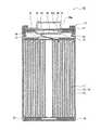
図1は、実施形態の一例である非水電解質二次電池10の断面図である。
非水電解質二次電池10は、正極11と、負極12と、非水電解質とを備える。正極11と負極12との間には、セパレータ13を設けることが好適である。非水電解質二次電池10は、例えば正極11及び負極12がセパレータ13を介して巻回されてなる巻回型の電極体14と、非水電解質とが電池ケースに収容された構造を有する。なお、巻回型の電極体14の代わりに、正極及び負極がセパレータを介して交互に積層されてなる積層型の電極体など、他の形態の電極体が適用されてもよい。電極体14及び非水電解質を収容する電池ケースとしては、円筒形、角形、コイン形、ボタン形等の金属製ケース、樹脂シートをラミネートして形成された樹脂製ケース(ラミネート型電池)などが例示できる。図1に示す例では、有底円筒形状のケース本体15と封口体16とにより電池ケースが構成されている。FIG. 1 is a cross-sectional view of a non-aqueous electrolyte
The non-aqueous electrolyte
非水電解質二次電池10は、電極体14の上下にそれぞれ配置された絶縁板17,18を備える。図1に示す例では、正極11に取り付けられた正極リード19が絶縁板17の貫通孔を通って封口体16側に延び、負極12に取り付けられた負極リード20が絶縁板18の外側を通ってケース本体15の底部側に延びている。例えば、正極リード19は封口体16の底板であるフィルタ22の下面に溶接等で接続され、フィルタ22と電気的に接続された封口体16の天板であるキャップ26が正極端子となる。負極リード20はケース本体15の底部内面に溶接等で接続され、ケース本体15が負極端子となる。本実施形態では、封口体16に電流遮断機構(CID)及びガス排出機構(安全弁)が設けられている。なお、ケース本体15の底部にも、ガス排出弁(図示せず)を設けることが好適である。 The non-aqueous electrolyte
ケース本体15は、例えば有底円筒形状の金属製容器である。ケース本体15と封口体16との間には、ガスケット27が設けられ、電池ケース内部の密閉性が確保される。ケース本体15は、例えば側面部を外側からプレスして形成された、封口体16を支持する張り出し部21を有することが好適である。張り出し部21は、ケース本体15の周方向に沿って環状に形成されることが好ましく、その上面で封口体16を支持する。 The
封口体16は、フィルタ開口部22aが形成されたフィルタ22と、フィルタ22上に配置された弁体とを有する。弁体は、フィルタ22のフィルタ開口部22aを塞いでおり、内部短絡等による発熱で電池の内圧が上昇した場合に破断する。本実施形態では、弁体として下弁体23及び上弁体25が設けられており、下弁体23と上弁体25の間に配置される絶縁部材24、及びキャップ開口部26aを有するキャップ26がさらに設けられている。封口体16を構成する各部材は、例えば円板形状又はリング形状を有し、絶縁部材24を除く各部材は互いに電気的に接続されている。具体的には、フィルタ22と下弁体23が各々の周縁部で互いに接合され、上弁体25とキャップ26も各々の周縁部で互いに接合されている。下弁体23と上弁体25は、各々の中央部で互いに接続され、各周縁部の間には絶縁部材24が介在している。なお、内部短絡等による発熱で内圧が上昇すると、例えば下弁体23が薄肉部で破断し、これにより上弁体25がキャップ26側に膨れて下弁体23から離れることにより両者の電気的接続が遮断される。 The sealing
非水電解質二次電池10は、例えば体積エネルギー密度が600Wh/L以上である。後述するように、非水電解質二次電池10は、正極活物質にリチウム遷移金属酸化物を用い、負極活物質にリチウムイオンを吸蔵・放出可能な材料を用いる。より詳しくは、正極活物質にはコバルト(Co)を含有するリチウム遷移金属酸化物が、負極活物質にはケイ素(Si)を含有する材料がそれぞれ用いられる。さらに、非水電解質としてフッ素化鎖状カルボン酸エステルを含む非水溶媒を用いる。 The non-aqueous electrolyte
[正極]
正極は、例えば金属箔等の正極集電体と、正極集電体上に形成された正極合材層とで構成される。正極集電体には、アルミニウムなどの正極の電位範囲で安定な金属の箔、当該金属を表層に配置したフィルム等を用いることができる。正極合材層は、正極活物質の他に、導電材及び結着材を含むことが好適である。正極は、例えば正極集電体上に正極活物質、結着材等を含む正極合材スラリーを塗布し、塗膜を乾燥させた後、圧延して正極合材層を集電体の両面に形成することにより作製できる。[Positive electrode]
The positive electrode is composed of a positive electrode current collector such as a metal foil and a positive electrode mixture layer formed on the positive electrode current collector. As the positive electrode current collector, a metal foil such as aluminum that is stable in the potential range of the positive electrode, a film in which the metal is arranged on the surface layer, or the like can be used. The positive electrode mixture layer preferably contains a conductive material and a binder in addition to the positive electrode active material. For the positive electrode, for example, a positive electrode mixture slurry containing a positive electrode active material, a binder, etc. is applied onto a positive electrode current collector, the coating film is dried, and then rolled to apply a positive electrode mixture layer to both sides of the current collector. It can be produced by forming.
正極活物質は、層状構造を有し、Liを除く金属元素の総量に対するCoの含有量が1mol%以上20mol%未満であるリチウム遷移金属酸化物(以下、「リチウム遷移金属酸化物A」とする)を主成分とする。リチウム遷移金属酸化物Aの結晶構造は、例えば六方晶であり、空間群R−3mに帰属される対称性を有する。正極活物質はリチウム遷移金属酸化物A以外の材料を含んでいてもよいが、リチウム遷移金属酸化物Aは、正極活物質の総重量に対して、少なくとも50重量%含まれ、好ましくは80重量%以上、より好ましくは90重量%以上含まれる。本実施形態では、正極活物質としてリチウム遷移金属酸化物Aのみを用いるものとして説明する。Coを含有するリチウム遷移金属酸化物Aを用いることにより、Siを含有する負極活物質の表面に良質な被膜が形成されると考えられ、高入出力特性と高耐久性を両立することが可能となる。 The positive electrode active material has a layered structure, and the content of Co with respect to the total amount of metal elements excluding Li is 1 mol% or more and less than 20 mol%. Lithium transition metal oxide (hereinafter referred to as “lithium transition metal oxide A”). ) Is the main component. The crystal structure of the lithium transition metal oxide A is, for example, hexagonal and has symmetry attributed to the space group R-3m. The positive electrode active material may contain a material other than the lithium transition metal oxide A, but the lithium transition metal oxide A is contained in an amount of at least 50% by weight, preferably 80% by weight, based on the total weight of the positive electrode active material. % Or more, more preferably 90% by weight or more. In the present embodiment, it will be described that only the lithium transition metal oxide A is used as the positive electrode active material. By using the lithium transition metal oxide A containing Co, it is considered that a high-quality film is formed on the surface of the negative electrode active material containing Si, and it is possible to achieve both high input / output characteristics and high durability. It becomes.
リチウム遷移金属酸化物AにおけるCoの含有量は、上記のように、1mol%以上20mol%未満であり、好ましくは2mol%〜15mol%、より好ましくは3mol%〜12mol%である。リチウム遷移金属酸化物Aは、放電状態又は未反応状態において、例えば一般式LiaCoxM1-xO2(0.9≦a≦1.2、0.01≦x<0.2、MはNi、Mn、Alから選択される少なくとも1種を含む金属元素)で表される。金属元素Mとしては、例えばCo、ニッケル(Ni)、マンガン(Mn)以外の遷移金属元素、アルカリ金属元素、アルカリ土類金属元素、第12族元素、アルミニウム(Al)以外の第13族元素、及び第14族元素が挙げられる。具体的には、ホウ素(B)、マグネシウム(Mg)、チタン(Ti)、クロム(Cr)、鉄(Fe)、銅(Cu)、亜鉛(Zn)、ジルコニウム(Zr)、ストロンチウム(Sr)、ニオブ(Nb)、モリブデン(Mo)、錫(Sn)、タンタル(Ta)、タングステン(W)、ナトリウム(Na)、カリウム(K)、バリウム(Ba)、カルシウム(Ca)等が例示できる。As described above, the content of Co in the lithium transition metal oxide A is 1 mol% or more and less than 20 mol%, preferably 2 mol% to 15 mol%, and more preferably 3 mol% to 12 mol%. The lithium transition metal oxide A is, in a discharged state or an unreacted state, for example, in the general formula Lia Cox M1-x O2 (0.9 ≦ a ≦ 1.2, 0.01 ≦ x <0.2, M is represented by a metal element containing at least one selected from Ni, Mn, and Al). Examples of the metal element M include transition metal elements other than Co, nickel (Ni), and manganese (Mn), alkali metal elements, alkaline earth metal elements,
リチウム遷移金属酸化物Aは、Liを除く金属元素の総量に対するNiの含有量が80mol%以上であることが好ましく、85mol%以上であることがより好ましい。Niの含有量が80mol%以上であれば、入出力特性及び耐久性がさらに向上する。リチウム遷移金属酸化物Aは、放電状態又は未反応状態において、例えば一般式LiaCoxNiyM1-x-yO2(0.9≦a≦1.2、0.01≦x<0.2、0.8≦y<1.0、0<x+y<1、MはMn、Alから選択される少なくとも1種を含む金属元素)で表される。好適なリチウム遷移金属酸化物Aの一例は、Ni−Co−Al系、Ni−Co−Mn系の複合酸化物である。The lithium transition metal oxide A preferably has a Ni content of 80 mol% or more, more preferably 85 mol% or more, based on the total amount of metal elements other than Li. When the Ni content is 80 mol% or more, the input / output characteristics and durability are further improved. The lithium transition metal oxide A is, for example, in the discharged state or the unreacted state, for example, in the general formula Lia Cox NyM 1-xy O2 (0.9 ≦ a ≦ 1.2, 0.01 ≦ x <0. 2, 0.8 ≦ y <1.0, 0 <x + y <1, M is a metal element containing at least one selected from Mn and Al). An example of a suitable lithium transition metal oxide A is a Ni—Co—Al-based or Ni—Co—Mn-based composite oxide.
リチウム遷移金属酸化物Aの粒径(レーザー回折法により測定される体積平均粒径)は、特に限定されないが、好ましくは2μm〜30μmである。リチウム遷移金属酸化物の粒子は、例えば粒径50nm〜10μmの一次粒子が結合した二次粒子である。リチウム遷移金属酸化物Aの粒子表面には、例えば酸化タングステン、リン酸リチウム等の無機化合物粒子が固着していてもよい。 The particle size of the lithium transition metal oxide A (volume average particle size measured by the laser diffraction method) is not particularly limited, but is preferably 2 μm to 30 μm. The particles of the lithium transition metal oxide are, for example, secondary particles to which primary particles having a particle size of 50 nm to 10 μm are bonded. Inorganic compound particles such as tungsten oxide and lithium phosphate may be adhered to the particle surface of the lithium transition metal oxide A.
上記導電材は、正極合材層の電気伝導性を高めるために用いられる。導電材の例としては、カーボンブラック(CB)、アセチレンブラック(AB)、ケッチェンブラック、黒鉛等の炭素材料などが挙げられる。これらは、単独で用いてもよく、2種類以上を組み合わせて用いてもよい。 The conductive material is used to enhance the electrical conductivity of the positive electrode mixture layer. Examples of the conductive material include carbon materials such as carbon black (CB), acetylene black (AB), Ketjen black, and graphite. These may be used alone or in combination of two or more.
上記結着材は、正極活物質及び導電材間の良好な接触状態を維持し、且つ正極集電体表面に対する正極活物質等の結着性を高めるために用いられる。結着材の例としては、ポリテトラフルオロエチレン(PTFE)、ポリフッ化ビニリデン(PVdF)等のフッ素系樹脂、ポリアクリロニトリル(PAN)、ポリイミド系樹脂、アクリル系樹脂、ポリオレフィン系樹脂などが挙げられる。また、これらの樹脂と、カルボキシメチルセルロース(CMC)又はその塩(CMC−Na、CMC−K、CMC-NH4等、また部分中和型の塩であってもよい)、ポリエチレンオキシド(PEO)等が併用されてもよい。これらは、単独で用いてもよく、2種類以上を組み合わせて用いてもよい。The binder is used to maintain a good contact state between the positive electrode active material and the conductive material, and to enhance the binding property of the positive electrode active material or the like to the surface of the positive electrode current collector. Examples of the binder include fluororesins such as polytetrafluoroethylene (PTFE) and polyvinylidene fluoride (PVdF), polyacrylonitrile (PAN), polyimide resins, acrylic resins, and polyolefin resins. Further, these resins, carboxymethyl cellulose (CMC) or a salt thereof (CMC-Na, CMC-K, CMC-NH4, etc., or a partially neutralized salt), polyethylene oxide (PEO), etc. May be used in combination. These may be used alone or in combination of two or more.
[負極]
負極は、例えば金属箔等からなる負極集電体と、当該集電体上に形成された負極合材層とで構成される。負極集電体には、銅などの負極の電位範囲で安定な金属の箔、当該金属を表層に配置したフィルム等を用いることができる。負極合材層は、負極活物質の他に、結着材を含むことが好適である。負極は、例えば負極集電体上に負極活物質、結着材等を含む負極合材スラリーを塗布し、塗膜を乾燥させた後、圧延して負極合材層を集電体の両面に形成することにより作製できる。[Negative electrode]
The negative electrode is composed of a negative electrode current collector made of, for example, a metal foil, and a negative electrode mixture layer formed on the current collector. As the negative electrode current collector, a metal foil that is stable in the potential range of the negative electrode such as copper, a film in which the metal is arranged on the surface layer, or the like can be used. The negative electrode mixture layer preferably contains a binder in addition to the negative electrode active material. For the negative electrode, for example, a negative electrode mixture slurry containing a negative electrode active material, a binder, etc. is applied onto a negative electrode current collector, the coating film is dried, and then rolled to apply a negative electrode mixture layer to both sides of the current collector. It can be produced by forming.
負極活物質には、上記のように、Siを含有する材料が用いられる。Siは、黒鉛などの炭素材料と比べてより多くのリチウムイオンを吸蔵できることから、負極活物質に適用することで電池の高容量化を図ることができる。また、負極活物質中にSiを含有させることで、高入出力特性と高耐久性を両立することが可能となる。Siを含有する材料としては、Siを用いてもよいが、好ましくはケイ素酸化物(以下、「ケイ素酸化物B」とする)を用いる。 As the negative electrode active material, a material containing Si is used as described above. Since Si can occlude more lithium ions than carbon materials such as graphite, it is possible to increase the capacity of the battery by applying it to the negative electrode active material. Further, by containing Si in the negative electrode active material, it is possible to achieve both high input / output characteristics and high durability. As the material containing Si, Si may be used, but silicon oxide (hereinafter referred to as "silicon oxide B") is preferably used.
ケイ素酸化物Bは、SiOx(0.8≦x≦1.5)で表される酸化物が好適である。SiOxは、例えば非晶質のSiO2のマトリックス中に微細なSiが分散した構造を有する。SiOx粒子を透過型電子顕微鏡(TEM)で観察すると、Siの存在が確認できる。SiはSiO2のマトリックス中に、200nm以下のサイズで均一に分散していることが好ましい。なお、SiOx粒子は、リチウムシリケート(例えば、Li2SiO3、Li2Si2O5等)を含んでいてもよい。ケイ素酸化物Bの粒径(レーザー回折法により測定される体積平均粒径)は、例えば1μm〜15μmであり、好ましくは4μm〜10μmである。The silicon oxide B ispreferably an oxide represented by SiO x (0.8 ≦ x ≦ 1.5). SiOx has a structure in which fine Si is dispersed in a matrix ofamorphous SiO 2 , for example. The presence of Si can be confirmed by observing the SiOx particles with a transmission electron microscope (TEM). It is preferable that Si isuniformly dispersed in the matrix of SiO 2 in a size of 200 nm or less. The SiOx particles may contain lithium silicate (for example, Li2 SiO3 , Li2 Si2 O5, etc.). The particle size of the silicon oxide B (volume average particle size measured by the laser diffraction method) is, for example, 1 μm to 15 μm, preferably 4 μm to 10 μm.
ケイ素酸化物Bは、SiOxよりも導電性の高い材料から構成される導電層を粒子表面に有することが好適である。導電層を構成する導電材料としては、電気化学的に安定なものが好ましく、炭素材料、金属、及び金属化合物からなる群より選択される少なくとも1種であることが好ましい。導電層を構成する炭素材料には、正極合材層の導電材と同様に、カーボンブラック、アセチレンブラック、ケッチェンブラック、黒鉛、及びこれらの2種以上の混合物などを用いることができる。It is preferable that the silicon oxide B has a conductive layer made of a material having a higher conductivity thanSiO x on the particle surface. As the conductive material constituting the conductive layer, an electrochemically stable material is preferable, and at least one selected from the group consisting of a carbon material, a metal, and a metal compound is preferable. As the carbon material constituting the conductive layer, carbon black, acetylene black, Ketjen black, graphite, a mixture of two or more of these, and the like can be used as in the case of the conductive material of the positive electrode mixture layer.
上記導電層の厚みは、導電性の確保とケイ素酸化物Bへのリチウムイオンの拡散性を考慮して、1nm〜200nmが好ましく、5nm〜100nmがより好ましい。導電層の厚みは、走査型電子顕微鏡(SEM)等を用いた粒子の断面観察により計測できる。導電層は、例えばCVD法、スパッタリング法、メッキ法(電解・無電解メッキ)等の従来公知の方法を用いて形成できる。CVD法によりケイ素酸化物Bの粒子表面に炭素材料からなる導電層を形成する場合、例えばケイ素酸化物Bの粒子と炭化水素系ガスを気相中にて加熱し、炭化水素系ガスの熱分解により生じた炭素を粒子上に堆積させる。 The thickness of the conductive layer is preferably 1 nm to 200 nm, more preferably 5 nm to 100 nm, in consideration of ensuring conductivity and diffusing lithium ions into the silicon oxide B. The thickness of the conductive layer can be measured by observing the cross section of the particles using a scanning electron microscope (SEM) or the like. The conductive layer can be formed by using a conventionally known method such as a CVD method, a sputtering method, or a plating method (electrolytic / electroless plating). When a conductive layer made of a carbon material is formed on the surface of silicon oxide B particles by the CVD method, for example, the silicon oxide B particles and the hydrocarbon gas are heated in the gas phase to thermally decompose the hydrocarbon gas. The carbon produced by is deposited on the particles.
負極活物質としては、サイクル特性等を考慮して、ケイ素酸化物Bと黒鉛を併用することが好適である。即ち、負極活物質は、ケイ素酸化物Bと黒鉛との混合物からなる。負極活物質は、黒鉛以外の炭素材料等をさらに含んでいてもよいが、実質的にケイ素酸化物Bと黒鉛のみで構成されることが好ましい。ケイ素酸化物Bの含有量は、電池容量、入出力特性、サイクル特性の向上等の観点から、負極活物質の総重量に対して1重量%〜20重量%であることが好ましい。より好ましくは2重量%〜15重量%、特に好ましくは3重量%〜10重量%である。黒鉛の含有量は、例えば負極活物質の総重量に対して80重量%〜99重量%である。即ち、ケイ素酸化物Bと黒鉛の割合(混合比)は、重量比で99:1〜80:20が好ましく、98:2〜85:15がより好ましく、97:3〜90:10が特に好ましい。 As the negative electrode active material, it is preferable to use silicon oxide B and graphite in combination in consideration of cycle characteristics and the like. That is, the negative electrode active material is composed of a mixture of silicon oxide B and graphite. The negative electrode active material may further contain a carbon material other than graphite, but is preferably composed substantially only of silicon oxide B and graphite. The content of the silicon oxide B is preferably 1% by weight to 20% by weight with respect to the total weight of the negative electrode active material from the viewpoint of improving the battery capacity, input / output characteristics, cycle characteristics, and the like. It is more preferably 2% by weight to 15% by weight, and particularly preferably 3% by weight to 10% by weight. The graphite content is, for example, 80% by weight to 99% by weight with respect to the total weight of the negative electrode active material. That is, the ratio (mixing ratio) of silicon oxide B and graphite is preferably 99: 1 to 80:20, more preferably 98: 2 to 85:15, and particularly preferably 97: 3 to 90:10 in terms of weight ratio. ..
ケイ素酸化物Bと併用される黒鉛には、従来から非水電解質二次電池の負極活物質として使用されている黒鉛、例えば鱗片状黒鉛、塊状黒鉛、土状黒鉛等の天然黒鉛、塊状人造黒鉛(MAG)、黒鉛化メソフェーズカーボンマイクロビーズ(MCMB)等の人造黒鉛などを用いることができる。黒鉛の粒径(レーザー回折法により測定される体積平均粒径)は、例えば5〜30μmであり、好ましくは10〜25μmである。 The graphite used in combination with silicon oxide B includes graphite that has been conventionally used as a negative electrode active material for non-aqueous electrolyte secondary batteries, for example, natural graphite such as scaly graphite, massive graphite, and earthy graphite, and massive artificial graphite. (MAG), artificial graphite such as graphitized mesophase carbon microbeads (MCMB) can be used. The particle size of graphite (volume average particle size measured by laser diffraction method) is, for example, 5 to 30 μm, preferably 10 to 25 μm.
上記結着材としては、正極の場合と同様にフッ素系樹脂、PAN、ポリイミド系樹脂、アクリル系樹脂、ポリオレフィン系樹脂等を用いることができる。水系溶媒を用いて負極合材スラリーを調製する場合は、スチレン−ブタジエンゴム(SBR)、CMC又はその塩、ポリアクリル酸(PAA)又はその塩(PAA−Na、PAA−K等、また部分中和型の塩であってもよい)、ポリビニルアルコール(PVA)等を用いることが好ましい。 As the binder, a fluorine-based resin, a PAN, a polyimide-based resin, an acrylic resin, a polyolefin-based resin, or the like can be used as in the case of the positive electrode. When preparing a negative mixture slurry using an aqueous solvent, styrene-butadiene rubber (SBR), CMC or a salt thereof, polyacrylic acid (PAA) or a salt thereof (PAA-Na, PAA-K, etc.), or in a portion thereof. It may be a Japanese salt), polyvinyl alcohol (PVA), etc. are preferably used.
[セパレータ]
セパレータには、イオン透過性及び絶縁性を有する多孔性シートが用いられる。多孔性シートの具体例としては、微多孔薄膜、織布、不織布等が挙げられる。セパレータの材質としては、ポリエチレン、ポリプロピレン等のオレフィン系樹脂、セルロースなどが好適である。セパレータは、セルロース繊維層及びオレフィン系樹脂等の熱可塑性樹脂繊維層を有する積層体であってもよい。また、ポリエチレン層及びポリプロピレン層を含む多層セパレータであってもよく、セパレータの表面にアラミド系樹脂等の樹脂が塗布されたものを用いてもよい。[Separator]
As the separator, a porous sheet having ion permeability and insulating property is used. Specific examples of the porous sheet include a microporous thin film, a woven fabric, and a non-woven fabric. As the material of the separator, olefin resins such as polyethylene and polypropylene, cellulose and the like are suitable. The separator may be a laminate having a cellulose fiber layer and a thermoplastic resin fiber layer such as an olefin resin. Further, it may be a multilayer separator containing a polyethylene layer and a polypropylene layer, or a separator coated with a resin such as an aramid resin may be used.
セパレータと正極及び負極の少なくとも一方との界面には、無機物のフィラーを含むフィラー層が形成されていてもよい。無機物のフィラーとしては、例えばTi、Al、Si、Mgの少なくとも1種を含有する酸化物、リン酸化合物などが挙げられる。フィラー層は、例えば当該フィラーを含有するスラリーを正極、負極、又はセパレータの表面に塗布して形成することができる。 A filler layer containing an inorganic filler may be formed at the interface between the separator and at least one of the positive electrode and the negative electrode. Examples of the inorganic filler include oxides and phosphoric acid compounds containing at least one of Ti, Al, Si, and Mg. The filler layer can be formed, for example, by applying a slurry containing the filler to the surface of the positive electrode, the negative electrode, or the separator.
[非水電解質]
非水電解質は、非水溶媒と、非水溶媒に溶解した電解質塩とを含む。非水溶媒は、上記のように、少なくともフッ素化鎖状カルボン酸エステルを含む。非水溶媒には、例えばフッ素化鎖状カルボン酸エステル以外のエステル類、エーテル類、ニトリル類、ジメチルホルムアミド等のアミド類、及びこれらの2種以上の混合溶媒等を用いることができる。また、プロパンスルトン等のスルホン基含有化合物を用いてもよい。非水溶媒は、これら溶媒の水素の少なくとも一部をフッ素等のハロゲン原子で置換したハロゲン置換体を含んでいてもよい。[Non-aqueous electrolyte]
The non-aqueous electrolyte contains a non-aqueous solvent and an electrolyte salt dissolved in the non-aqueous solvent. The non-aqueous solvent contains at least a fluorinated chain carboxylic acid ester as described above. As the non-aqueous solvent, for example, esters other than the fluorinated chain carboxylic acid ester, ethers, nitriles, amides such as dimethylformamide, and a mixed solvent of two or more of these can be used. Further, a sulfone group-containing compound such as propane sultone may be used. The non-aqueous solvent may contain a halogen substituent in which at least a part of hydrogen in these solvents is substituted with a halogen atom such as fluorine.
上記フッ素化鎖状カルボン酸エステルには、炭素数3〜5のフッ素化鎖状カルボン酸エステルを用いることが好適である。具体例としては、フッ素化プロピオン酸メチル、フッ素化プロピオン酸エチル、フッ素化酢酸メチル、フッ素化酢酸エチル、フッ素化酢酸プロピル等が挙げられる。これらのうち、フッ素化プロピオン酸メチル(FMP)、特に3,3,3−トリフルオロプロピオン酸メチルを用いることが好ましい。フッ素化鎖状カルボン酸エステルの含有量は、非水電解質を構成する非水溶媒の総体積に対して40体積%〜90体積%が好ましい。フッ素化鎖状カルボン酸エステルの含有量が当該範囲内であれば、負極表面にイオン透過性に優れた良質な被膜が形成され易くなる。 As the fluorinated chain carboxylic acid ester, it is preferable to use a fluorinated chain carboxylic acid ester having 3 to 5 carbon atoms. Specific examples include methyl fluorinated propionate, ethyl fluorinated propionate, methyl fluorinated acetate, ethyl fluorinated acetate, propyl fluorinated acetate and the like. Of these, methyl fluorinated propionate (FMP), particularly methyl 3,3,3-trifluoropropionate, is preferably used. The content of the fluorinated chain carboxylic acid ester is preferably 40% by volume to 90% by volume with respect to the total volume of the non-aqueous solvent constituting the non-aqueous electrolyte. When the content of the fluorinated chain carboxylic acid ester is within the above range, a high-quality film having excellent ion permeability is likely to be formed on the surface of the negative electrode.
上記エステル類(上記フッ素化鎖状カルボン酸エステル以外)の例としては、エチレンカーボネート(EC)、プロピレンカーボネート(PC)、ブチレンカーボネート、ビニレンカーボネート等の環状炭酸エステル、ジメチルカーボネート(DMC)、メチルエチルカーボネート(EMC)、ジエチルカーボネート(DEC)、メチルプロピルカーボネート、エチルプロピルカーボネート、メチルイソプロピルカーボネート等の鎖状炭酸エステル、γ−ブチロラクトン(GBL)、γ−バレロラクトン(GVL)等の環状カルボン酸エステル、これら溶媒の水素の少なくとも一部をフッ素等のハロゲン原子で置換したハロゲン置換体などが挙げられる。また、非水溶媒は、非フッ素化鎖状カルボン酸エステルを含んでいてもよい。 Examples of the above esters (other than the above fluorinated chain carboxylic acid esters) include cyclic carbonates such as ethylene carbonate (EC), propylene carbonate (PC), butylene carbonate, vinylene carbonate, dimethyl carbonate (DMC), and methyl ethyl. Chain carbonates such as carbonate (EMC), diethyl carbonate (DEC), methylpropyl carbonate, ethylpropyl carbonate, methylisopropyl carbonate, cyclic carboxylic acid esters such as γ-butyrolactone (GBL), γ-valerolactone (GVL), Examples thereof include halogen substituents in which at least a part of hydrogen in these solvents is replaced with a halogen atom such as fluorine. Moreover, the non-aqueous solvent may contain a non-fluorinated chain carboxylic acid ester.
上記エーテル類の例としては、1,3−ジオキソラン、4−メチル−1,3−ジオキソラン、テトラヒドロフラン、2−メチルテトラヒドロフラン、プロピレンオキシド、1,2−ブチレンオキシド、1,3−ジオキサン、1,4−ジオキサン、1,3,5−トリオキサン、フラン、2−メチルフラン、1,8−シネオール、クラウンエーテル等の環状エーテル、1,2−ジメトキシエタン、ジエチルエーテル、ジプロピルエーテル、ジイソプロピルエーテル、ジブチルエーテル、ジヘキシルエーテル、エチルビニルエーテル、ブチルビニルエーテル、メチルフェニルエーテル、エチルフェニルエーテル、ブチルフェニルエーテル、ペンチルフェニルエーテル、メトキシトルエン、ベンジルエチルエーテル、ジフェニルエーテル、ジベンジルエーテル、o−ジメトキシベンゼン、1,2−ジエトキシエタン、1,2−ジブトキシエタン、ジエチレングリコールジメチルエーテル、ジエチレングリコールジエチルエーテル、ジエチレングリコールジブチルエーテル、1,1−ジメトキシメタン、1,1−ジエトキシエタン、トリエチレングリコールジメチルエーテル、テトラエチレングリコールジメチル等の鎖状エーテル類、これら溶媒の水素の少なくとも一部をフッ素等のハロゲン原子で置換したハロゲン置換体などが挙げられる。 Examples of the above ethers include 1,3-dioxolane, 4-methyl-1,3-dioxolane, tetrahydrofuran, 2-methyltetrahexyl, propylene oxide, 1,2-butylene oxide, 1,3-dioxane, 1,4. -Cyclic ethers such as dioxane, 1,3,5-trioxane, furan, 2-methylfuran, 1,8-cineole, crown ether, 1,2-dimethoxyethane, diethyl ether, dipropyl ether, diisopropyl ether, dibutyl ether , Dihexyl ether, ethyl vinyl ether, butyl vinyl ether, methyl phenyl ether, ethyl phenyl ether, butyl phenyl ether, pentyl phenyl ether, methoxy toluene, benzyl ethyl ether, diphenyl ether, dibenzyl ether, o-dimethoxybenzene, 1,2-diethoxy Chain ethers such as ethane, 1,2-dibutoxyethane, diethylene glycol dimethyl ether, diethylene glycol diethyl ether, diethylene glycol dibutyl ether, 1,1-dimethoxymethane, 1,1-diethoxyethane, triethylene glycol dimethyl ether, tetraethylene glycol dimethyl, etc. Examples thereof include halogen-substituted products in which at least a part of hydrogen in these solvents is replaced with a halogen atom such as fluorine.
上記ニトリル類の例としては、アセトニトリル、プロピオニトリル、ブチロニトリル、バレロニトリル、n−ヘプタンニトリル、スクシノニトリル、グルタロニトリル、アジポニトリル、ピメロニトリル、1,2,3−プロパントリカルボニトリル、1,3,5−ペンタントリカルボニトリル、これら溶媒の水素の少なくとも一部をフッ素等のハロゲン原子で置換したハロゲン置換体などが挙げられる。 Examples of the above nitriles include acetonitrile, propionitrile, butyronitrile, valeronitrile, n-heptanenitrile, succinonitrile, glutaronitrile, adipoynitrile, pimeronitrile, 1,2,3-propanetricarbonitrile, 1,3. , 5-Pentanetricarbonitrile, halogen-substituted products in which at least a part of hydrogen in these solvents is replaced with a halogen atom such as fluorine.
非水溶媒としては、フッ素化鎖状カルボン酸エステルと、環状カーボネート、特にフッ素化環状カーボネートとを併用することが特に好適である。フッ素化鎖状カルボン酸エステル及びフッ素化環状カーボネートの合計の含有量は、非水溶媒の総体積に対して50体積%以上とすることが好ましく、80体積%以上がより好ましい。フッ素化鎖状カルボン酸エステルの含有量は、上記のように、非水溶媒の総体積に対して40体積%〜90体積%が好ましく、50体積%〜85体積%がより好ましい。フッ素化環状カーボネートの含有量は、非水溶媒の総体積に対して、例えば3体積%〜20体積%である。フッ素化鎖状カルボン酸エステルと併用されるフッ素化環状カーボネートとしては、例えば4−フルオロエチレンカーボネート(FEC)、4,5−ジフルオロ−1,3−ジオキソラン−2−オン、4,4−ジフルオロ−1,3−ジオキソラン−2−オン、4−フルオロ−5−メチル−1,3−ジオキソラン−2−オン、4−フルオロ‐4−メチル−1,3−ジオキソラン−2−オン、4−トリフルオロメチル−1,3−ジオキソラン−2−オン、4,5−ジフルオロ−4,5−ジメチル−1,3−ジオキソラン−2−オン(DFBC)等が挙げられる。これらのうち、FECが特に好ましい。 As the non-aqueous solvent, it is particularly preferable to use a fluorinated chain carboxylic acid ester and a cyclic carbonate, particularly a fluorinated cyclic carbonate, in combination. The total content of the fluorinated chain carboxylic acid ester and the fluorinated cyclic carbonate is preferably 50% by volume or more, more preferably 80% by volume or more, based on the total volume of the non-aqueous solvent. As described above, the content of the fluorinated chain carboxylic acid ester is preferably 40% by volume to 90% by volume, more preferably 50% by volume to 85% by volume, based on the total volume of the non-aqueous solvent. The content of the fluorinated cyclic carbonate is, for example, 3% by volume to 20% by volume with respect to the total volume of the non-aqueous solvent. Examples of the fluorinated cyclic carbonate used in combination with the fluorinated chain carboxylic acid ester include 4-fluoroethylene carbonate (FEC), 4,5-difluoro-1,3-dioxolane-2-one, and 4,4-difluoro-. 1,3-Dioxolan-2-one, 4-fluoro-5-methyl-1,3-dioxolan-2-one, 4-fluoro-4-methyl-1,3-dioxolan-2-one, 4-trifluoro Examples thereof include methyl-1,3-dioxolan-2-one, 4,5-difluoro-4,5-dimethyl-1,3-dioxolan-2-one (DFBC) and the like. Of these, FEC is particularly preferred.
電解質塩は、リチウム塩であることが好ましい。リチウム塩の例としては、LiBF4、LiClO4、LiPF6、LiAsF6、LiSbF6、LiAlCl4、LiSCN、LiCF3SO3、LiC(C2F5SO2)、LiCF3CO2、Li(P(C2O4)F4)、Li(P(C2O4)F2)、LiPF6-x(CnF2n+1)x(1<x<6、nは1又は2)、LiB10Cl10、LiCl、LiBr、LiI、クロロボランリチウム、低級脂肪族カルボン酸リチウム、Li2B4O7、Li(B(C2O4)2)[リチウム−ビスオキサレートボレート(LiBOB)]、Li(B(C2O4)F2)等のホウ酸塩類、LiN(FSO2)2、LiN(C1F2l+1SO2)(CmF2m+1SO2){l、mは1以上の整数}等のイミド塩類などが挙げられる。リチウム塩は、これらを1種単独で用いてもよいし、複数種を混合して用いてもよい。これらのうち、イオン伝導性、電気化学的安定性等の観点から、少なくともフッ素含有リチウム塩を用いることが好ましく、例えばLiPF6を用いることが好ましい。特に高温環境下においても負極の表面に安定な皮膜を形成する点から、フッ素含有リチウム塩とオキサラト錯体をアニオンとするリチウム塩(例えば、LiBOB)とを併用することが好適である。リチウム塩の濃度は、非水溶媒1L当り0.8〜1.8molとすることが好ましい。The electrolyte salt is preferably a lithium salt. Examples of the lithiumsalt, LiBF 4, LiClO 4, LiPF 6, LiAsF 6, LiSbF 6, LiAlCl 4, LiSCN, LiCF 3 SO 3, LiC (C 2 F 5 SO 2), LiCF 3 CO 2, Li (P (C2 O4 ) F4 ), Li (P (C2 O4 ) F2 ), LiPF6-x (Cn F2n + 1 )x (1 <x <6, n is 1 or 2), LiB10 Cl10 , LiCl, LiBr, LiI, Lithiumchloroborane, Lithium lower aliphatic carboxylate, Li 2 B4 O7 , Li (B (C2 O4 )2 ) [Lithium-bisoxalate volate (LiBOB) ], Li (B (C2 O4 ) F2 ) and other borates, LiN (FSO2 )2 , LiN (C1 F2l + 1 SO2 ) (Cm F2m + 1 SO2 ) {l , M is an integer of 1 or more} and other imide salts. As the lithium salt, these may be used alone or a plurality of types may be mixed and used. Of these, from the viewpoint of ionic conductivity, electrochemical stability, etc., it is preferable to use at least a fluorine-containing lithium salt, and for example, LiPF6 is preferably used. In particular, from the viewpoint of forming a stable film on the surface of the negative electrode even in a high temperature environment, it is preferable to use a fluorine-containing lithium salt and a lithium salt having an oxalate complex as an anion (for example, LiBOB) in combination. The concentration of the lithium salt is preferably 0.8 to 1.8 mol per 1 L of the non-aqueous solvent.
以下、実施例により本開示をさらに詳説するが、本開示はこれらの実施例に限定されるものではない。 Hereinafter, the present disclosure will be described in more detail with reference to Examples, but the present disclosure is not limited to these Examples.
<実施例1>
[正極の作製]
正極活物質としてLiNi0.88Co0.09Al0.03O2で表されるリチウムニッケルコバルトアルミニウム複合酸化物を100重量部と、アセチレンブラック(AB)を1重量部と、ポリフッ化ビニリデン(PVdF)を1重量部とを混合し、さらにN−メチル−2−ピロリドン(NMP)を適量加えて、正極合材スラリーを調製した。次に、当該正極合材スラリーをアルミニウム箔からなる正極集電体の両面に塗布し、乾燥させた。これを所定の電極サイズに切り取り、ローラーを用いて圧延し、正極集電体の両面に正極合材層が形成された正極を作製した。なお、LiNi0.88Co0.09Al0.03O2の結晶構造は、層状岩塩構造(六方晶、空間群R3−m)である。<Example 1>
[Cathode preparation]
As a positive electrode active material, 100 parts by weight of lithium nickel cobalt aluminum composite oxide represented by LiNi 0.88 Co0.09 Al0.03 O2 , 1 part by weight of acetylene black (AB), and 1 part by weight of polyvinylidene fluoride (PVdF). , And an appropriate amount of N-methyl-2-pyrrolidone (NMP) was added to prepare a positive electrode mixture slurry. Next, the positive electrode mixture slurry was applied to both sides of the positive electrode current collector made of aluminum foil and dried. This was cut into a predetermined electrode size and rolled using a roller to prepare a positive electrode having positive electrode mixture layers formed on both sides of the positive electrode current collector. The crystal structure of LiNi0.88 Co0.09 Al0.03 O2 is a layered rock salt structure (hexagonal crystal, space group R3-m).
[負極の作製]
負極活物質として粒子表面が炭素被覆された酸化ケイ素(SiO)を4重量部、及び黒鉛粉末(C)を96重量部と、カルボキシメチルセルロース(CMC)を1重量部と、スチレン−ブタジエンゴム(SBR)を1重量部とを混合し、さらに水を適量加えて、負極合材スラリーを調製した。次に、当該負極合材スラリーを銅箔からなる負極集電体の両面に塗布し、乾燥させた。これを所定の電極サイズに切り取り、ローラーを用いて圧延し、負極集電体の両面に負極合材層が形成された負極を作製した。[Preparation of negative electrode]
As the negative electrode active material, 4 parts by weight of silicon oxide (SiO) whose particle surface is carbon-coated, 96 parts by weight of graphite powder (C), 1 part by weight of carboxymethyl cellulose (CMC), and styrene-butadiene rubber (SBR). ) Was mixed with 1 part by weight, and an appropriate amount of water was further added to prepare a negative electrode mixture slurry. Next, the negative electrode mixture slurry was applied to both sides of the negative electrode current collector made of copper foil and dried. This was cut into a predetermined electrode size and rolled using a roller to prepare a negative electrode having negative electrode mixture layers formed on both sides of the negative electrode current collector.
[非水電解質の作製]
4−フルオロエチレンカーボネート(FEC)と、3,3,3−トリフルオロプロピオン酸メチル(FMP)とを、15:85の体積比で混合した。当該混合溶媒に、LiPF6を1.2mol/Lの濃度となるように溶解させて非水電解質を作製した。なお、電解液100重量部に対して、ビニレンカーボネートを0.5重量部、及びプロペンスルトン1重量部を添加した。[Preparation of non-aqueous electrolyte]
4-Fluoroethylene carbonate (FEC) and methyl 3,3,3-trifluoropropionate (FMP) were mixed in a volume ratio of 15:85.A non-aqueous electrolyte was prepared by dissolving LiPF 6 in the mixed solvent so as to have a concentration of 1.2 mol / L. To 100 parts by weight of the electrolytic solution, 0.5 part by weight of vinylene carbonate and 1 part by weight of propene sultone were added.
[電池の作製]
上記正極にアルミニウムリードを、上記負極にニッケルリードをそれぞれ取り付け、セパレータを介して正極及び負極を渦巻き状に巻回することにより巻回型の電極体を作製した。セパレータには、ポリエチレン製の微多孔膜の片面にポリアミドとアルミナのフィラーを分散させた耐熱層を形成したものを用いた。当該電極体を、外径18.2mm、高さ65mmの有底円筒形状の電池ケース本体に収容し、上記非水電解液を注入した後、ガスケット及び封口体により電池ケース本体の開口部を封口して18650型の円筒形非水電解質二次電池X1を作製した。[Battery production]
An aluminum lead was attached to the positive electrode and a nickel reed was attached to the negative electrode, and the positive electrode and the negative electrode were spirally wound via a separator to prepare a wound electrode body. As the separator, a heat-resistant layer in which polyamide and alumina fillers were dispersed was formed on one side of a polyethylene microporous film. The electrode body is housed in a bottomed cylindrical battery case body having an outer diameter of 18.2 mm and a height of 65 mm, and after injecting the non-aqueous electrolyte solution, the opening of the battery case body is sealed with a gasket and a sealing body. Then, a 18650 type cylindrical non-aqueous electrolyte secondary battery X1 was produced.
<比較例1>
FMPの代わりにEMCを用いて非水電解質を作製したこと以外は、実施例1と同様にして電池Y1を作製した。<Comparative example 1>
Battery Y1 was prepared in the same manner as in Example 1 except that EMC was used instead of FMP to prepare a non-aqueous electrolyte.
<比較例2>
負極活物質として酸化ケイ素を用いず黒鉛のみを用いたこと以外は、実施例1と同様にして電池Y2を作製した。<Comparative example 2>
Battery Y2 was produced in the same manner as in Example 1 except that silicon oxide was not used as the negative electrode active material and only graphite was used.
<比較例3>
FMPの代わりにEMCを用いて非水電解質を作製したこと以外は、比較例2と同様にして電池Y3を作製した。<Comparative example 3>
The battery Y3 was prepared in the same manner as in Comparative Example 2 except that the non-aqueous electrolyte was prepared using EMC instead of FMP.
<比較例4>
LiNi0.88Co0.09Al0.03O2の代わりにLiNi0.50Co0.20Mn0.30O2を用いて正極を作製したこと以外は、実施例1と同様にして電池Y4を作製した。<Comparative example 4>
Battery Y4 was prepared in the same manner as in Example 1 except that a positive electrode was prepared usingLiNi 0.50 Co0.20 Mn0.30 O2 instead of LiNi0.88 Co0.09 Al0.03 O2.
<比較例5>
FMPの代わりにEMCを用いて非水電解質を作製したこと以外は、比較例4と同様にして電池Y5を作製した。<Comparative example 5>
The battery Y5 was prepared in the same manner as in Comparative Example 4 except that the non-aqueous electrolyte was prepared using EMC instead of FMP.
<比較例6>
負極活物質として酸化ケイ素を用いず黒鉛のみを用いたこと以外は、比較例4と同様にして電池Y6を作製した。<Comparative Example 6>
A battery Y6 was produced in the same manner as in Comparative Example 4 except that silicon oxide was not used as the negative electrode active material and only graphite was used.
<比較例7>
FMPの代わりにEMCを用いて非水電解質を作製したこと以外は、比較例6と同様にして電池Y7を作製した。<Comparative Example 7>
Battery Y7 was prepared in the same manner as in Comparative Example 6 except that EMC was used instead of FMP to prepare a non-aqueous electrolyte.
[入出力特性の評価]
上記各電池について、下記充放電サイクルを繰り返した後の抵抗値を測定して、入出力特性の評価とした。
0.3It(1000mA)で定格容量の100%まで充電させた〔即ち、充電深度(SOC)が100%となった〕後、25℃の条件の下で、開回路電圧から0.5It(1500mA)の電流値で20秒間放電を行った。放電開始20秒後の電圧と放電開始直前の電圧により、下記の式1を用いて25℃での抵抗値を算出した。なお、セルY1〜Y7の各セルの抵抗値は、セルX1の抵抗値を100%としたときの相対値で示した。
For each of the above batteries, the resistance value after repeating the following charge / discharge cycle was measured to evaluate the input / output characteristics.
After charging to 100% of the rated capacity at 0.3 It (1000 mA) [that is, the charging depth (SOC) becomes 100%], 0.5 It (1500 mA) from the open circuit voltage under the condition of 25 ° C. ) Was discharged for 20 seconds. The resistance value at 25 ° C. was calculated using the following equation 1 from the
[サイクル特性(耐久性)の評価]
上記各電池について、下記充放電サイクルを繰り返した後の容量維持率を測定して、サイクル特性(耐久性)の評価とした。
25℃の温度環境下において、各電池を0.3It(1000mA)mAの定電流で電池電圧が4.2Vとなるまで充電し、電池電圧が4.2Vに達した後は定電圧で充電した。次に、0.3It(1000mA)mAの定電流で電池電圧が3.0Vとなるまで放電を行い、このときの放電容量(初期容量)を求めた。この充放電サイクルを繰り返し行い、100サイクル後の放電容量を初期容量で除した値に100をかけて、容量維持率を算出した。[Evaluation of cycle characteristics (durability)]
For each of the above batteries, the capacity retention rate after repeating the following charge / discharge cycle was measured to evaluate the cycle characteristics (durability).
In a temperature environment of 25 ° C., each battery was charged with a constant current of 0.3 It (1000 mA) mA until the battery voltage reached 4.2 V, and after the battery voltage reached 4.2 V, it was charged at a constant voltage. .. Next, the battery was discharged at a constant current of 0.3 It (1000 mA) mA until the battery voltage became 3.0 V, and the discharge capacity (initial capacity) at this time was determined. This charge / discharge cycle was repeated, and the value obtained by dividing the discharge capacity after 100 cycles by the initial capacity was multiplied by 100 to calculate the capacity retention rate.
表1の結果から分かるように、正極活物質としてLiNi0.88Co0.09Al0.03O2で表される複合酸化物が、負極活物質としてSiを含有する材料がそれぞれ用いられ、非水電解質にFMPが含まれる電池X1は、比較例の各電池に比べて抵抗値が低く、且つ容量維持率が高い。即ち、電池X1は、比較例の各電池と比べて高い入出力特性と良好なサイクル特性を有する。この結果は、充電時に正極から溶出するCoがSiを含有する負極活物質の表面でフッ素化鎖状カルボン酸エステルと特異的に反応して、CoとSiとを含んだイオン透過性に優れた良質な被膜を形成することによると考えられる。一方、負極活物質にSiが含有されない場合(電池Y2,3,6,7)、Coの含有量が20mol%以上である場合(電池Y4〜7)は、抵抗値が高く、良好な入出力特性が得られない。負極活物質にSiを含まない場合は、負極表面に形成された被膜にもSiが含まれず、電池X1のような被膜が形成されず、抵抗値が増加したと考えられる。Co量が多くなり過ぎると、Siを含有する負極活物質の表面に形成されるFMPとの被膜が厚くなり過ぎて抵抗値が増加したと考えられる。また、Co量が少なすぎると(例えば1mol%未満)、良質な被膜を十分に形成するために必要なCoが少ないと考えられる。なお、比較例の各電池では、FMPを添加することにより却って抵抗値が上昇している。つまり、上述した本開示の構成を適用した場合にのみ、高入出力特性と長寿命化の両立できるという作用効果が特異的に得られる。As can be seen from the results in Table 1,a composite oxide represented by LiNi 0.88 Co0.09 Al0.03 O2 is used as the positive electrode active material, and a material containing Si is used as the negative electrode active material, and FMP is used as the non-aqueous electrolyte. The included battery X1 has a lower resistance value and a higher capacity retention rate than each battery of the comparative example. That is, the battery X1 has higher input / output characteristics and better cycle characteristics than each battery of the comparative example. As a result, Co eluted from the positive electrode during charging specifically reacts with the fluorinated chain carboxylic acid ester on the surface of the negative electrode active material containing Si, and is excellent in ion permeability containing Co and Si. It is considered that this is due to the formation of a good quality film. On the other hand, when the negative electrode active material does not contain Si (batteries Y2, 3, 6, 7) and the Co content is 20 mol% or more (batteries Y4 to 7), the resistance value is high and good input / output is performed. No characteristics can be obtained. When the negative electrode active material does not contain Si, it is considered that the film formed on the surface of the negative electrode does not contain Si, the film like the battery X1 is not formed, and the resistance value increases. It is considered that when the amount of Co becomes too large, the film with FMP formed on the surface of the negative electrode active material containing Si becomes too thick and the resistance value increases. Further, if the amount of Co is too small (for example, less than 1 mol%), it is considered that the amount of Co required to sufficiently form a good quality film is small. In each battery of the comparative example, the resistance value is rather increased by adding FMP. That is, only when the above-described configuration of the present disclosure is applied, the effect of achieving both high input / output characteristics and long life can be specifically obtained.
10 非水電解質二次電池、11 正極、12 負極、13 セパレータ、14 電極体、15 ケース本体、16 封口体、17,18 絶縁板、19 正極リード、20 負極リード、22 フィルタ、22a フィルタ開口部、23 下弁体、24 絶縁部材、25 上弁体、26 キャップ、26a キャップ開口部、27 ガスケット 10 Non-aqueous electrolyte secondary battery, 11 Positive electrode, 12 Negative electrode, 13 Separator, 14 Electrode body, 15 Case body, 16 Seal body, 17, 18 Insulation plate, 19 Positive electrode lead, 20 Negative electrode lead, 22 filter, 22a Filter opening , 23 Lower valve body, 24 Insulation member, 25 Upper valve body, 26 Cap, 26a Cap opening, 27 Gasket
Claims (2)
Translated fromJapaneseケイ素(Si)を含有する負極活物質を含む負極と、
フッ素化鎖状カルボン酸エステルと4−フルオロエチレンカーボネートとを含む非水電解質と、
を備え、
前記リチウム遷移金属酸化物は、空間群R−3mに帰属される結晶構造を有し、
前記負極活物質は、SiOx(0.8≦x≦1.5)で表されるケイ素酸化物と、黒鉛との混合物からなり、
前記ケイ素酸化物の含有量は、前記負極活物質の総重量に対して1重量%〜20重量%であり、前記黒鉛の含有量は80重量%〜99重量%であり、
前記フッ素化鎖状カルボン酸エステルの含有量は、前記非水電解質を構成する非水溶媒の総体積に対して40体積%〜90体積%であり、
前記フッ素化鎖状カルボン酸エステルと4−フルオロエチレンカーボネートとの合計の含有量は、前記非水電解質を構成する非水溶媒の総体積に対して50体積%以上である、非水電解質二次電池。It has a layered structure, the content of cobalt (Co) with respect to the total amount of metal elements excluding lithium (Li) is 1 mol% or more and less than 20 mol%, and the content of nickel (Ni) with respect to the total amount of metal elements excluding Li is A positive electrode containing a positive electrode active material containing lithium transition metal oxide as a main component, which is 80 mol% or more, and a positive electrode.
Negative electrode containing silicon (Si) Negative electrode containing active material and
A non-aqueous electrolyte containing a fluorinated chain carboxylic acid ester and4-fluoroethylene carbonate,
With
The lithium transition metal oxide has a crystal structure belonging to the space group R-3m and has a crystal structure.
The negative electrode active material is composed of a mixture of silicon oxide represented by SiOx (0.8 ≦ x ≦ 1.5) and graphite.
The content of the silicon oxide is 1% by weight to 20% by weight with respect to the total weight of the negative electrode active material, and the content of the graphite is 80% by weight to 99% by weight.
The content of the fluorinated chain carboxylic acid ester is 40% by volume to 90% by volume with respect to the total volume of the non-aqueous solvent constituting the non-aqueous electrolyte.
The total content of the fluorinated chain carboxylic acid ester and4-fluoroethylene carbonate is 50% by volume or more based on the total volume of the non-aqueous solvent constituting the non-aqueous electrolyte. battery.
The non-aqueous electrolyte secondary battery according to claim 1, wherein the fluorinated chain carboxylic acid ester is methyl fluorinated propionate.
Applications Claiming Priority (3)
| Application Number | Priority Date | Filing Date | Title |
|---|---|---|---|
| JP2014264893 | 2014-12-26 | ||
| JP2014264893 | 2014-12-26 | ||
| PCT/JP2015/006293WO2016103657A1 (en) | 2014-12-26 | 2015-12-17 | Nonaqueous electrolyte secondary cell |
Publications (2)
| Publication Number | Publication Date |
|---|---|
| JPWO2016103657A1 JPWO2016103657A1 (en) | 2017-10-05 |
| JP6847665B2true JP6847665B2 (en) | 2021-03-24 |
Family
ID=56149720
Family Applications (1)
| Application Number | Title | Priority Date | Filing Date |
|---|---|---|---|
| JP2016565909AActiveJP6847665B2 (en) | 2014-12-26 | 2015-12-17 | Non-aqueous electrolyte secondary battery |
Country Status (4)
| Country | Link |
|---|---|
| US (1) | US20170317380A1 (en) |
| JP (1) | JP6847665B2 (en) |
| CN (1) | CN107078340B (en) |
| WO (1) | WO2016103657A1 (en) |
Families Citing this family (14)
| Publication number | Priority date | Publication date | Assignee | Title |
|---|---|---|---|---|
| US20180212269A1 (en)* | 2015-09-29 | 2018-07-26 | Panasonic Intellectual Property Management Co., Ltd. | Nonaqueous electrolyte secondary battery |
| CN110024198B (en)* | 2016-12-28 | 2022-05-03 | 松下电器产业株式会社 | Non-aqueous electrolyte secondary battery |
| JP6858797B2 (en)* | 2017-01-30 | 2021-04-14 | パナソニック株式会社 | Non-aqueous electrolyte secondary battery |
| CN110892559B (en)* | 2017-10-31 | 2023-01-10 | 松下知识产权经营株式会社 | Positive electrode for nonaqueous electrolyte secondary battery, and nonaqueous electrolyte secondary battery |
| JP6962154B2 (en)* | 2017-11-27 | 2021-11-05 | 株式会社豊田自動織機 | Lithium ion secondary battery |
| KR102522751B1 (en)* | 2018-03-29 | 2023-04-17 | 미쯔비시 케미컬 주식회사 | Non-aqueous electrolyte and non-aqueous electrolyte battery |
| KR102321503B1 (en)* | 2018-06-12 | 2021-11-02 | 주식회사 엘지에너지솔루션 | Anode Active Material of Lithium Secondary Battery and Lithium Secondary Battery Comprising the Same |
| CN113261142B (en)* | 2018-12-28 | 2025-03-14 | 松下新能源株式会社 | Method for manufacturing non-aqueous electrolyte secondary battery and method for testing voltage |
| WO2021039119A1 (en)* | 2019-08-30 | 2021-03-04 | パナソニックIpマネジメント株式会社 | Nonaqueous electrolyte secondary battery |
| CN114450820B (en)* | 2019-09-30 | 2024-05-28 | 株式会社村田制作所 | Secondary battery |
| US12359025B2 (en) | 2019-11-04 | 2025-07-15 | Solvay Specialty Polymers Usa, Llc | Poly(arylene sulfide) polymers and corresponding polymer compositions and articles |
| KR20220120798A (en)* | 2021-02-23 | 2022-08-31 | 주식회사 엘지에너지솔루션 | Electrode assembly having an high energy density, and lithium secondary batterys containing the same |
| US20250006997A1 (en)* | 2021-09-30 | 2025-01-02 | Panasonic Intellectual Property Management Co., Ltd. | Nonaqueous electrolyte secondary battery |
| WO2024074565A1 (en)* | 2022-10-05 | 2024-04-11 | Northvolt Ab | A lithium ion battery cell |
Family Cites Families (11)
| Publication number | Priority date | Publication date | Assignee | Title |
|---|---|---|---|---|
| JP2002124261A (en)* | 1999-11-29 | 2002-04-26 | Mitsui Chemicals Inc | Positive electrode active material for lithium secondary battery and battery |
| JP4557920B2 (en)* | 2006-03-30 | 2010-10-06 | 株式会社東芝 | Non-aqueous electrolyte battery |
| JP5235437B2 (en)* | 2007-02-20 | 2013-07-10 | 三洋電機株式会社 | Non-aqueous electrolyte for secondary battery and non-aqueous electrolyte secondary battery |
| JP5461883B2 (en)* | 2008-08-05 | 2014-04-02 | 三洋電機株式会社 | Non-aqueous electrolyte for secondary battery and non-aqueous electrolyte secondary battery |
| JP2012104335A (en)* | 2010-11-09 | 2012-05-31 | Sanyo Electric Co Ltd | Nonaqueous electrolyte secondary battery |
| JP2012209245A (en)* | 2011-03-16 | 2012-10-25 | Sanyo Electric Co Ltd | Nonaqueous electrolyte secondary battery |
| WO2012132060A1 (en)* | 2011-03-28 | 2012-10-04 | 日本電気株式会社 | Secondary battery and electrolyte |
| WO2013015069A1 (en)* | 2011-07-28 | 2013-01-31 | 三洋電機株式会社 | Non-aqueous electrolyte secondary cell |
| US20140356724A1 (en)* | 2011-12-22 | 2014-12-04 | Sanyo Electric Co., Ltd. | Non-aqueous electrolyte secondary battery |
| JP2014049286A (en)* | 2012-08-31 | 2014-03-17 | Sanyo Electric Co Ltd | Nonaqueous electrolyte secondary battery |
| JP6084628B2 (en)* | 2012-10-31 | 2017-02-22 | 三洋電機株式会社 | Nonaqueous electrolyte secondary battery |
- 2015
- 2015-12-17JPJP2016565909Apatent/JP6847665B2/enactiveActive
- 2015-12-17WOPCT/JP2015/006293patent/WO2016103657A1/enactiveApplication Filing
- 2015-12-17CNCN201580060633.4Apatent/CN107078340B/enactiveActive
- 2015-12-17USUS15/531,794patent/US20170317380A1/ennot_activeAbandoned
Also Published As
| Publication number | Publication date |
|---|---|
| JPWO2016103657A1 (en) | 2017-10-05 |
| WO2016103657A1 (en) | 2016-06-30 |
| US20170317380A1 (en) | 2017-11-02 |
| CN107078340B (en) | 2020-05-12 |
| CN107078340A (en) | 2017-08-18 |
Similar Documents
| Publication | Publication Date | Title |
|---|---|---|
| JP6847665B2 (en) | Non-aqueous electrolyte secondary battery | |
| JP6948601B2 (en) | Rechargeable battery | |
| JP6602130B2 (en) | Positive electrode for non-aqueous electrolyte secondary battery and non-aqueous electrolyte secondary battery | |
| CN108713265B (en) | Nonaqueous electrolyte secondary battery | |
| JP2019029205A (en) | Positive electrode for nonaqueous electrolyte secondary battery, and nonaqueous electrolyte secondary battery | |
| JP7270155B2 (en) | Non-aqueous electrolyte secondary battery | |
| WO2016151983A1 (en) | Nonaqueous electrolyte secondary battery | |
| JP6655819B2 (en) | Non-aqueous electrolyte secondary battery | |
| JPWO2018221024A1 (en) | Positive electrode for secondary battery and secondary battery | |
| JPWO2019098056A1 (en) | Lithium ion secondary battery | |
| JPWO2018105539A1 (en) | Anode for non-aqueous electrolyte secondary battery and non-aqueous electrolyte secondary battery | |
| JPWO2019131194A1 (en) | Positive electrode active material for non-aqueous electrolyte secondary batteries, positive electrode for non-aqueous electrolyte secondary batteries and non-aqueous electrolyte secondary batteries | |
| JPWO2016084357A1 (en) | Nonaqueous electrolyte secondary battery | |
| JP2018056066A (en) | Anode for non-aqueous electrolyte secondary battery and non-aqueous electrolyte secondary battery | |
| JPWO2019107068A1 (en) | Non-aqueous electrolyte secondary battery | |
| US11626593B2 (en) | Negative electrode for non-aqueous electrolyte secondary battery, and non-aqueous electrolyte secondary battery | |
| WO2016151979A1 (en) | Negative electrode for nonaqueous electrolyte secondary batteries and nonaqueous electrolyte secondary battery | |
| JP2019145204A (en) | Positive electrode active material, positive electrode and nonaqueous electrolyte secondary battery | |
| CN111033820B (en) | Positive electrode for nonaqueous electrolyte secondary battery and nonaqueous electrolyte secondary battery | |
| JP2018163781A (en) | Nonaqueous electrolyte secondary battery | |
| JP2021099948A (en) | Anode for non-aqueous electrolyte secondary battery and non-aqueous electrolyte secondary battery | |
| JP6728135B2 (en) | Non-aqueous electrolyte secondary battery | |
| JP2013137939A (en) | Nonaqueous secondary battery | |
| JP7153890B2 (en) | Positive electrode for non-aqueous electrolyte secondary battery, and non-aqueous electrolyte secondary battery | |
| JP7665440B2 (en) | Non-aqueous electrolyte secondary battery |
Legal Events
| Date | Code | Title | Description |
|---|---|---|---|
| A521 | Request for written amendment filed | Free format text:JAPANESE INTERMEDIATE CODE: A523 Effective date:20170411 | |
| A621 | Written request for application examination | Free format text:JAPANESE INTERMEDIATE CODE: A621 Effective date:20180704 | |
| A131 | Notification of reasons for refusal | Free format text:JAPANESE INTERMEDIATE CODE: A131 Effective date:20190521 | |
| A521 | Request for written amendment filed | Free format text:JAPANESE INTERMEDIATE CODE: A523 Effective date:20190717 | |
| A131 | Notification of reasons for refusal | Free format text:JAPANESE INTERMEDIATE CODE: A131 Effective date:20191008 | |
| A521 | Request for written amendment filed | Free format text:JAPANESE INTERMEDIATE CODE: A523 Effective date:20191205 | |
| A131 | Notification of reasons for refusal | Free format text:JAPANESE INTERMEDIATE CODE: A131 Effective date:20200407 | |
| A521 | Request for written amendment filed | Free format text:JAPANESE INTERMEDIATE CODE: A523 Effective date:20200528 | |
| A131 | Notification of reasons for refusal | Free format text:JAPANESE INTERMEDIATE CODE: A131 Effective date:20201104 | |
| TRDD | Decision of grant or rejection written | ||
| A01 | Written decision to grant a patent or to grant a registration (utility model) | Free format text:JAPANESE INTERMEDIATE CODE: A01 Effective date:20210202 | |
| A61 | First payment of annual fees (during grant procedure) | Free format text:JAPANESE INTERMEDIATE CODE: A61 Effective date:20210303 | |
| R150 | Certificate of patent or registration of utility model | Ref document number:6847665 Country of ref document:JP Free format text:JAPANESE INTERMEDIATE CODE: R150 | |
| S531 | Written request for registration of change of domicile | Free format text:JAPANESE INTERMEDIATE CODE: R313531 | |
| R350 | Written notification of registration of transfer | Free format text:JAPANESE INTERMEDIATE CODE: R350 | |
| S111 | Request for change of ownership or part of ownership | Free format text:JAPANESE INTERMEDIATE CODE: R313111 | |
| R350 | Written notification of registration of transfer | Free format text:JAPANESE INTERMEDIATE CODE: R350 |